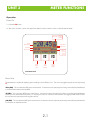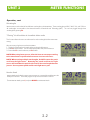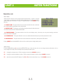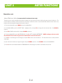
1
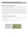
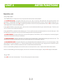
MicroMeter
Optical Power Meter
Operations Manual
Firmware Version 1.20e
September 15, 2003
Extech Part Numbers: MO500, MO510, MO520
Table of Contents
Preface
Why Use An Optical Power Meter?
Checking the MicroMeter Firmware Version
ii
ii
ii
Unit 1 - Introduction
Description
Applications
General Features
Keyboard Entry Method
1-1
1-1
1-2
1-2
Unit 2 - Meter Functions
Power ON
Power Units Supported by the MicroMeter
Wavelengths Supported by the MicroMeter
“Zeroing” the MicroMeter
Monitor Mode
Main Menu
Meter Setup
Manual Reference Method
Stored Data Menu
Power OFF
2-1
2-1
2-2
2-2
2-2
2-3
2-3
2-4
2-5
2-5
Unit 3 - Fiber Certification
Overview
Operation
Power ON
Fiber Certification
Definition of a Link
Required Equipment
Preparation
Reference Method
Step 1 - Select Link
Step 2 - Define Link
Step 3 - Take Readings
Step 4 - Stored Data
3-1
3-1
3-1
3-1
3-1
3-1
3-1
3-1
3-2
3-2
3-3
3-3
UNIT 4 - Appendices
Appendix A - Decibel Review
Appendix B - Dynamic Range Review
Appendix C - Glossary
Appendix D - MicroMeter Specifications
Appendix E - Warranty Information
Appendix F - Cleaning and Care Instructions
Appendix G - Accessories
Appendix H - Link Budget Calculation Worksheet
Appendix I - Reference Jumper Setup
4-1
4-2
4-2
4-6
4-6
4-7
4-8
4-9
4-10
i
PREFACE
Why Use An Optical Fiber Power Meter?
Standards organizations such as the TIA or the ISO/IEC provide performance standards that the cabling plant must adhere to in order
to support high-speed protocols such as Gigabit Ethernet. Fiber can be tested against these standards, ensuring that it is able to
handle the high amount of traffic with a maximum amount of reliability.
These standards organizations also provide standards for administration of the cabling plant. These standards require a fiber link to be
certified; that is, a report must be generated from appropriate test equipment for tracking and auditing purposes. These reports can
also be used as verification of compliance to performance standards in case a question comes up about the quality of an installation.
These signed documents cover the installer from liability provided that the link meets specified performance standards.
Our optical fiber power meters are designed with these standards in mind because we understand the importance of qualifying your
fiber installations with standards-compliant test equipment. The meter you have just purchased also prints professionally formatted
reports showing the conformity to these popular industry standards. You can print out these reports as a record of the original
conformity to quality set by the standards. These documents signed by all associated parties may prove valuable in any future disputes
concerning the installation.
Checking The MicroMeter Firmware Version
This manual is written for the MicroMeter firmware version 1.20e. Follow the instructions below to verify the meter’s firmware version.
1)
Press ON to start up the meter.
2)
After the initial boot-up screen, the display should look like the diagram below. This screen only remains viewable for
approximately 2 seconds.
If the firmware version is not V1.20e, contact our tech support for the correct version of the manual.
Company Name
Company Phone
Serial Number
Firmware Version
.................
.............
SN:MX10001
V1
.20e
ii
UNIT 1
INTRODUCTION
Description
The MicroMeter is a high accuracy, high resolution, microprocessor controlled optical power meter. The meter has a wide dynamic
range making it ideal for both single and multi-mode fiber testing.
It has an attractive handheld case, a backlit graphical liquid crystal display, and 18-key keypad for easy data entry. The meter comes
with a small state-of-the-art UNIVERSAL adapter that is fully reliable for the use of ST, SC, FC or any 2.5 mm connectors which saves
money on consumables (test cables wear out). It will operate for over 100 hrs on a single 9v battery and has built in auto shutdown.
The MicroMeter includes a built-in link wizard that helps the user easily calculate the allowable loss for the fiber runs that they will be
measuring. The meter stores physical fiber information for up to four links. Link information includes: link name, date, fiber type, fiber
length, connectors, splices, temperature, and calculated or entered reference power values for four wavelengths. In addition the meter
will store up to 1000 measured data points with labels. Each value includes the fiber type and link.
The stored information can be selectively viewed, edited (measured again), printed, or deleted. The meter will print formatted reports
of selected stored data directly using the built in serial port, or all of the stored data can be downloaded to a computer spreadsheet or
our free Reporter software to produce professional-looking formatted certification reports.
Applications
The MicroMeter can be used for several applications. A listing of these applications and their descriptions follows:
Attenuation and Loss Measurements - After a fiber cable has been installed and terminated, it must be tested to determine if the
fiber is installed correctly. A comparison of the actual power measurement and the reference value determines the loss of the fiber link.
Fiber Network Certification - The MicroMeter uses a loss wizard that is used for fiber certification against the popular industry
cabling standard called the TIA/EIA 568. The user is prompted to enter several parameters, which allows the MicroMeter to calculate
a certification reference value and store it in the meter. As the user stores data points in the meter using the loss wizard, the actual
power level of the link is also stored. The data is then downloaded into our Reporter software, where the actual power value is
compared to the reference value. Certification reports can be printed out with details or summaries of the fibers being certified.
Fiber Continuity Testing - Continuity can be measured with the MicroMeter by placing a calibrated light source on one end of the
fiber and the MicroMeter on the other end. This is also a simple way to measure the attenuation of the fiber.
Patch Cord Testing - Fiber links that are producing incorrect results may have bad patch cords. The MicroMeter can be used to test
the attenuation of a patch cord to see if it is usable, or should be thrown out.
Active Equipment Optical Power Measurements - Active equipment needs to be measured periodically for correct power
levels and stability. The transmitters in this equipment have a known power value. The MicroMeter can be directly attached to this
equipment via a patch cord to check whether the transmitter is stable and is within the manufacturer’s specified power range.
1-1
UNIT 1
INTRODUCTION
General Features
1 2.5mm UNIVERSAL ADAPTER PORT - accepts standard 2.5mm ferrule connectors
(ST, SC, FC).
2
1
6
2 COMPUTER PORT - port for downloading data from the meter to a PC via serial cable.
3 LIQUID CRYSTAL DISPLAY (LCD) - displays power readings, menus, and
information necessary for operation of the meter. The elements of the display are
discussed in the appropriate units.
3
4 FUNCTION KEYS - activate the options on the Function Options Menu.
4
5 ALPHA NUMERIC KEYS - enter letters, numbers, and symbols into field prompts.
5
6 OPTIONAL LED LIGHT SOURCE - press the 4 key to activate the optional LED light
source
8
7
7 MENU KEY - used to enter the menu system.
8 DONE KEY - activates certain menu options.
9 BACK LIGHT KEY - toggles the LCD back light ON or OFF.
9
10 ON/OFF KEYS - turns the meter ON or OFF.
10
Keyboard Entry Method
Several screens in the MicroMeter menu system require the user to enter some input, e.g. a fiber length measurement or a descriptive
name for a fiber run. This feature allows the MicroMeter to become more user-friendly.
ALPHA-NUMERIC FIELDS. These fields allow the user to enter either a number, a letter, or a special character. This is accomplished by
pressing and holding the key until the desired character appears. When the key is released, the cursor automatically advances to the
next position.
NUMERIC FIELDS. These fields are for numeric input only, e.g. fiber length, user-defined reference values, etc. The cursor will
automatically advance once a number key is pressed. EXCEPTION: some numeric operators may be required, such as the minus sign,
or a decimal point. Special characters reside under the 0 key. In this case, they are treated like alpha-numeric fields.
Press the DONE key when character input is complete.
1-2
UNIT 2
METER FUNCTIONS
Operation
Power On
1) Press the ON button.
2) After a few seconds, a screen will appear that looks like the one below, which is called Immediate Mode.
Power Units
Power
Measurement
Link Name
Run Number
-20 .45
dBm
ABS
82
68%
............
FBR:00
850nm
_____________________
UNITS | STORE | WAVE
F1
F2
F3
Toggle
Power
Units
Store
Power
Reading
Toggle
Wave
Lengths
dBm (ABS)
dB (REL)
µW (ABS)
Temperature
Battery Life
Wavelength
850nm
1300nm
1310nm
1550nm
Immediate Mode
Power Units
The MicroMeter is capable of displaying power readings in three different units. The user may toggle through these units by pressing
F1.
dBm (ABS) - This is an absolute (ABS) power measurement. It shows how much optical power is being received by the photodetector
in decibels referenced to a milliwatt (dBm).
dB (REL) - This is a relative (REL) power measurement. It shows the amount of optical power being received by the photodetector
relative to a user-defined reference power (i.e. “zeroing” the meter). If a reference value has been set, toggling to REL mode will show
the user how much optical power is being lost in the link.
µW (ABS) - This is an absolute (ABS) power measurement. It shows the amount of optical power being received by the photodetector
in microwatts, or millionths of a watt.
2-1
UNIT 2
METER FUNCTIONS
Operation, cont.
Wavelengths
Measurements can be taken for four different wavelengths in the MicroMeter. These wavelengths are 850, 1300/1310, and 1550nm.
All wavelengths are traceable to the National Institute of Standards and Technology (NIST). The user may toggle through these
wavelengths by pressing F3.
“Zeroing” the MicroMeter in Immediate Meter mode
This function allows the user to set references for each wavelength for fiber attenuation
testing.
After connecting a light source to the MicroMeter:
1. Toggle the wavelength until it matches the wavelength of the source.
2. Press 0 to zero the meter. The user will be prompted to verify the set reference.
3. Press either F1 to set the reference, or F3 to abort.
NOTE: When using laser sources, allow the laser to warm up according
to the manufacturer specifications to ensure accurate references.
NOTE: When zeroing multiple wavelengths, do NOT remove the patch
cord from the light source. Removing the patch cord from the light
source will invalidate the optical reference for the wavelength that was
just set. Use a separate patch cord for each light source port.
Monitor Mode
Monitor Mode sends absolute power measurements in a comma delimited format to the
serial port in real time. A terminal program is required to view data in real time.
To enter Monitor Mode, press 5, and press DONE to exit Monitor Mode..
2-2
-20 .45
dBm
ABS
82
68%
............
FBR:00
850nm
_____________________
UNITS | STORE | WAVE
0
-20 .45
dBm
ABS
82
68%
FIBER LINK #1
Monitor...
850nm
_____________________
UNITS | STORE | WAVE
UNIT 2
METER FUNCTIONS
Operation, cont.
Main Menu
Advanced meter functions can be configured from the Main Menu. Options 1 through
4 are listed in a step-by-step order for certifying fiber links and will be explained in
greater detail later in this manual. Option 5 is explained below. Press MENU to enter
the menu.
<1>SELECT LINK - This option allows the user to select the fiber link to be used for the
test, as well as editing its descriptive name and test date.
MAIN
MENU
<1>SELECT LINK
<2>DEFINE LINK
<3>TAKE READINGS
<4>STORED DATA
<5>METER SETUP
<2>DEFINE LINK - This option is used to define the parameters of the fiber link which
are used to calculate the link’s PASS/FAIL threshold.
<3>TAKE READINGS - This option takes the user to the main display screen, where they can view power readings, store data
points, and switch wavelengths.
<4>STORED DATA - This option allows the user to view and download the data points previously stored in the meter.
<5>METER SETUP - This option allows the user to edit the owner information, and adjust the LCD contrast.
Pressing DONE from the MAIN MENU will return the user to the power reading display screen.
Meter Setup
From the MAIN MENU, press 5 to enter the METER SETUP menu. From this menu the user can change company information, such as
name and phone number, and can also adjust the contrast of the LCD screen.
F1 – changes the company name. Edit the company name and press DONE to continue.
F2 – change the company telephone number. Edit the company telephone number and press DONE to continue.
F3 – adjust the contrast of the LCD display. Press F1or F3 to set the contrast down or up. Press DONE to continue.
2-3
UNIT 2
METER FUNCTIONS
Operation, cont.
Manual Reference Method-recommended for advanced users only
The Micro can be used to certify fiber links (shown in detail in the next unit) or to measure link loss by setting a manual reference. The
manual reference method is used to measure the actual loss in a fiber link, and it is recommended that only those users who are very
familiar with calculating link budgets should use this method.
1) From Immediate Mode, press MENU to enter the MAIN MENU.
2) At the MAIN MENU, press 1 to SELECT LINK. Highlight a link, and press F3 to change the name and/or date. Press DONE to
continue.
3) Press F2 to LOAD the selected link, and press DONE to continue.
4) From the MAIN MENU, press 2 to DEFINE LINK. Press 2 to SET A MANUAL REFERENCE. NOTE: setting a reference with
this method will overwrite any previous certification or manual references.
5) Press F1 to scroll through the wavelengths, and press F2 to set the manual reference. The asterisk shows the currently selected
wavelength.
6) Type in the manual reference using the keypad, and press DONE to continue. Press DONE to return to the MAIN MENU.
7) Press 3 to return to Immediate Mode and TAKE READINGS. Data storage is covered in more detail in the next unit.
2-4
UNIT 2
METER FUNCTIONS
Operation, cont.
Stored Data Menu
The STORED DATA menu allows the user to manipulate data that is stored in the MicroMeter.
<1>VIEW/EDIT/LOAD - this option allows the user to view, edit, or load any data point that was previously stored in the
MicroMeter. The VIEW/EDIT/LOAD screen initially loads with the first data point stored in memory. To go to a different data point, use:
F1to scroll through the fiber names; F2 to scroll through the fiber runs for the currently selected fiber name; or F3 to scroll through the
wavelengths for the currently selected data point.
Pressing 0 will LOAD the selected data point, and return the user to Immediate Mode showing the selected data point. From there, the
user can continue saving data from that point.
Pressing 5 will EDIT (or reshoot) the selected data point. The user will be returned to Immediate Mode to re-save the data point. After
the data point is re-saved, the user is returned to the last data point that was previously stored.
<2>PRINT RANGE - this option allows the user to print data points to a serial device, such as a serial printer or terminal program.
The printout is formatted in an easy-to-read format.
<3>DELETE RANGE - this option allows the user to delete a range of data points, or delete all of the data points from the meter. This
should only be done after the data points have been downloaded into the PC with Reporter software.
<4>DOWNLOAD DATA - this option allows the user to download data either to Reporter software, or to a terminal program. Data
downloaded to a terminal program is in a Comma-Delimited format for easy placement into a program that can format CommaDelimited files. The PC must be connected to the meter via the MicroMeter download cable.
If the user is downloading to Reporter, then no further action is necessary from this screen. Reporter will handle the data transfer.
If the user is downloading to a terminal program, then the user must start the terminal program, and press F1 to begin the download.
Power OFF
Press OFF to shut down the MicroMeter. The user will be prompted to verify shutdown.
2-5
UNIT 3
FIBER CERTIFICATION
Overview
The whole purpose of fiber certification with the MicroMeter is to save data points using a standards-based reference point and
produce professional-looking reports for the customer.
The MicroMeter is capable of storing up to 1000 data points with user-configurable fiber labels, and can certify up to four separate
fiber links against the EIA/TIA 568 standard.
Data points are downloaded into our free Reporter Windows-compatible software for organizing data points and printing
professional-looking certification reports.
Operation
Power On
Press the F2 button. After a few seconds, the meter will display Immediate Mode (see Unit 2 for a description of the screen).
Fiber Certification
Before we begin, it is important to understand the term ‘LINK’ as it is used in the
MicroMeter.
Definition of a link: In the MicroMeter, a link is defined as any number of fibers, or fiber
runs, that all have the same set of fiber characteristics from one end to the other; typically
begin together and end together; and follow the same pathway. These characteristics
include fiber length, fiber type, connector loss, and splice loss, and the cabling standard
being used for fiber certification. NOTE: Any time one of these fiber
characteristics changes, a new link must be configured.
MAIN MENU
<1>SELECT LINK
<2>DEFINE LINK
<3>TAKE READINGS
<4>STORED DATA
<5>METER SETUP
REQUIRED EQUIPMENT
To perform fiber certification with the MicroMeter, the user will need the following equipment:
MicroMeter optical power meter
Stabilized light source (multi-mode or single mode, depending upon fiber type being tested)
Power meter test jumper (make sure the connectors match the fiber under test)
Light source test jumper (the user will need one jumper for each connector port on the light source)
Mandrel (½ inch; only for multi-mode fiber certification; the user will need one mandrel for each light source jumper)
PREPARATION
Make sure all of the required equipment is working properly:
– Clean the connector ports on the meter and light source
– Allow the light source to warm up according to manufacturer recommendations
– Clean and test the jumpers to make sure they are not adding significant loss to the test
REFERENCE METHOD - (see Appendix I for more details)
For proper certification of fiber links using the MicroMeter, use the following methods for setting certification references:
– Single mode fiber - EIA/TIA 526-7, Method 1.A
– Multi-mode fiber - EIA/TIA 526-14A, Method B
The following steps (Options 1 through 4 on the MAIN MENU) outline the procedure for setting up the MicroMeter for fiber
certification. The MAIN MENU takes the user through a step-by-step process to certify fiber links. This step-by-step process is called
the Link Wizard.
The Link Wizard calculates a PASS/FAIL threshold according to the link attenuation values detailed in the TIA/EIA 568 cabling standard.
All fibers included in the link are measured against this threshold to produce a PASS or FAIL reading.
3-1
UNIT 3
FIBER CERTIFICATION
Fiber Certification, cont.
STEP 1 - SELECT LINK
1-1) Press MENU to enter the MAIN MENU.
1-2) Press 1 to SELECT LINK.
1-3) At the STORED LINKS menu, the currently loaded link is denoted by an asterisk. Scroll through the list of links by pressing F1
to highlight the link to use. Press F3 to edit the name and the testing date of the selected link.
EDIT LINK
1-3a) Give the link a descriptive name. Press F1 to edit the name. Press DONE to continue.
1-3b) Enter the date of the test. Press F2 to enter the date. Press DONE to continue.
1-3c) When the name and date have been entered, press DONE to return to the STORED LINKS menu.
1-4) Press F2 to load the selected link. The user will be returned to the MAIN MENU.
STEP 2 - DEFINE LINK
2-1) Press 2 to DEFINE LINK.
2-2) Press 1 to CERTIFY LINK.
2-3) Scroll through the list of fiber types and highlight the link’s fiber type. Press F2 to select.
2-4) Enter the length of the fiber in meters. Press DONE to continue.
2-5) Enter the number of inline connections (connector pairs) in the link. Press DONE to continue.
2-6) Enter the number of inline splices in the link. Press DONE to continue.
2-7) Connect the light source for the wavelength shown on the display (remember: if the user is testing multi-mode fibers, the test
jumper must be wrapped 5-7 times around a mandrel). Press F1 or DONE to continue.
2-8) The settings the user just entered will appear on the display (see the example below).
SRC PWR (shown in dBm) - actual power the light source is emitting.
100 m (shown in dB) - attenuation value associated with the length and type of fiber the user entered.
0 CONN (shown in dB) - attenuation value of the connectors and splices the user entered.
REF PWR (dBm) - source power plus fiber attenuation plus connector and splice attenuation. This is the PASS / FAIL
threshold.
850nm - wavelength that the reference is being set for.
M6 - fiber type that the reference is being set for (M6 = 62.5 µm multi-mode, M5 = 50µm multiSRC PWR = -20.
24
mode, SI = single mode indoor, SO = single mode outdoor).
100 m = -00.
38
2-9) If any of the fiber characteristics were entered incorrectly, press F2. The user will be asked to repeat
steps 2-3 through 2-7.
0 CONN = +00.
00
REF PWR = -20.
62
850nm M6
_________________
WAVE | EDIT | SAVE
LEN | LINK | REF.
2-10) Press F3 to save the reference.
2-11) If the user is testing at an additional wavelength, press F1. The user will be prompted to connect a light source for the other
3-2
UNIT 3
FIBER CERTIFICATION
Fiber Certification, cont.
wavelength as in step 2-7. Repeat steps 2-7 through 2-10 for all
wavelengths the user is setting a reference for.
2-12) Press F1to continue. The user will be returned to the
MAIN MENU.
STEP 3 - TAKE READINGS
3-1) Press 3 to TAKE READINGS. The screen shown on the right
will appear. Take a moment to familiarize yourself with this screen.
Power Units
Power
Measurement
Fiber Link Name
Fiber ID
-20 .45
dBm
ABS
82
68%
FIBER LINK #1
850nm
FBR:00
_____________________
UNITS | STORE | WAVE
F1 - toggles power units between dBm (ABS), dB (REL), and µm
(ABS). In dB (REL) mode, the power measurement changes to show
the power level relative to the Link Wizard reference, and tells the
user if the link passes or fails according to the EIA/TIA 568 cabling
standard. A power reading with a minus sign means that the link
Store
Toggle
has failed the standard, and a plus sign means that the link passes.
Data
Power
Points
Units
F2 - stores the data point in memory for later download and report
printing. Each data point is conveniently stored with a userdefinable name and an auto-numbering system. In the diagram on the right, the label is the ‘FBR:’ in the
Fiber ID field. The ‘00 ‘ following the label is the auto-incrementing number. Each time a data point is
stored for a specific wavelength, this number goes up by 1.
F3 - toggles wavelength between 850nm, 1300nm, 1310nm, and 1550nm.
F1
F2
3-2) Press F2 to STORE a data point. The user may be prompted to enter a label. The user does not have
to change this label, but it is recommended to set the label to better describe the fiber runs being stored.
Press DONE to continue.
3-3) The user will be prompted to enter the fiber type. This fiber type must match the fiber type chosen in the
Link Wizard. Scroll through the fiber types with the F1 key, and press F2 to select. The user will only have to
enter the fiber type if they have not saved a data point for the current label.
3-4) Press F3 to save the current data point and continue on to the next fiber.
3-5) Repeat steps 3-2 and 3-4 for each data point to save. If the fiber label needs to be changed,
press F2 at the Data Point Save Screen and repeat steps 3-2 through 3-4.
dBm (ABS)
dB (REL)
µW (ABS)
Temperature
Battery Life
Wavelength
850nm
1300nm
1310nm
1550nm
F3
Toggle
Wave
Lengths
+ 245
.
dB
REL
82
<PASS 568> 68%
FIBER LINK #1
FBR:00
850nm
________________
UNITS|STORE|WAVE
dB (REL) Mode
PASS/FAIL
FIBER LINK #1
NAME = FBR:00
TYPE=62.5um MM
-22.05dBm 850nm
________________
PRINT| EDIT |
DATA | NAME |SAVE
Data Point
Save Screen
3-6) If the user is testing at additional wavelengths, press F3 to toggle to the next wavelength. The auto-increment number will begin at
‘00’ again, and have the same label. Repeat steps 3-2 and 3-4 for each data point being saved.
STEP 4 - STORED DATA
Before downloading certification data points to a PC, the user must first have installed free Reporter software on it. The software may be
downloaded from http://owl-inc.com/literature/sub/htm/owl_reporter.htm.
4-1) Press MENU to enter the MAIN MENU.
4-2) Press 4 to enter STORED DATA.
4-3) Press 4 to DOWNLOAD DATA.
3-3
UNIT 3
FIBER CERTIFICATION
Fiber Certification, cont.
4-4) Connect the MicroMeter to the PC via the download cable supplied with the meter.
4-5) Start the Reporter software on the PC.
4-6) Click the Download option on the menu bar, or the Download button on the button bar. The data points that are stored in the
meter will appear in the Reporter window. Press DONE to return to the STORED DATA menu, and press DONE again to return to
the MAIN MENU.
Once the data is downloaded into Reporter, we recommend that the user saves them as an Reporter file for permanent storage.
If hard copy of the data points is needed, the data points may be printed. There are two report options: summary and detail. The
summary printout lists all of the data points together, shows whether the link passed or failed, and shows the power level of the fiber.
The detail printout prints each individual fiber run on a single page, and shows detailed information about the run, including
whether the fiber passed or failed, and the remaining overhead of the fiber run.
3-4
UNIT 4
APPENDICES
Appendix A - Decibel Review
The MicroMeter meter has a decibel(dB) range that spans 75dB. The whole purpose of your meter is to measure light
energy in decibels. But what exactly is a decibel? It is not uncommon for a technician to be using an optical power meter
and not understand what a decibel really is. If you struggle a little with this review, you will find the concept not so
threatening.
This is what happens when we test a link: we send light of a specified wavelength from a stable light source down the fiber
optic cabling. The meter then captures this light and measures it. As light travels down this path, however, its photons
encounter impurities, connector gaps, and even the glass atoms themselves. All of these factors cause attenuation in the
fiber. If there is too much attenuation, your fiber optic link will fail, because it does not have enough power to trigger the
circuitry in the active receiver equipment. No communications can occur in this scenario.
Simply put, a decibel is a measure of the ratio of the power received at the end of a link relative to the power you started
with, which is known. This fraction calculates the relative power. This calculation is similar to test scores or percentages.
Amount of optical power left over at the end of the link
Amount of optical power at the beginning of the link
= Relative power out as a %
x100
If test results were kept in percent or fractions, the average person wouldn’t have difficulty in grasping the concept of
decibels. Unfortunately, in scientific measurement, graphing power measurements has become too cumbersome due to
their wide range of possible values; a person would need to paste lots of sheets of graph paper together to plot these power
functions by hand. So scientists came up with a little trick to “squeeze” the graph down to a more presentable size. The
trick uses logarithms (logs). Logs are fairly simple -- most of us have already encountered logs in pre-algebra class. They
didn’t seem so important then, but they are important to the understanding of decibels. Logs expressed in Base 10 are just
a way to state how many zeros there are in a number.
For example, log(10)=1, log(100)=2, log(1000)=3. Notice the pattern. Logs simply express how many places there
are after the first number. Let’s work with a number that isn’t 10, 100, or 1000. For instance the log(2014)=3.304.
Notice that 2014 has three digits beyond the first, thus the “3” in the 3.304. Also notice how it relates to the “3” in
log(1000)=3. Remember, logs are a tool we use to “squeeze” our measurements down so they will fit on graph paper.
LOG(
Amount of optical power left over at the end of the link
Amount of optical power at the beginning of the link
POWER AS
)= RELATIVE
A POWER OF 10
Power is measured in Watts (W), therefore:
LOG(
W
W
)
END OF LINK
BEGINNING OF LINK
=
RELATIVE POWER AS
A POWER OF 10
Mathematicians and scientists must have noticed that the shrinking effect of the graph was a little excessive. Logs in optical
decibels get multiplied by 10. Thus we finally have:
10 LOG(
W
W
END OF LINK
BEGINNING OF LINK
)
=RELATIVE POWER IN dB
Remember: Decibels are simply the ratio of the power received by the receiver over the power sent out by the light
source at the start of link.
4-1
UNIT 4
3
APPENDICES
APPENDICES
Appendix A - Decibel Review, cont.
There are other decibels to consider. The decibel we previously described is”dB” is called relative. This is because it is a
ratio as was explained. With ratios there is no way to tell what absolute value we had at the start or end of a link. To solve
the problem we can always reference our optical power to a fixed value of one milliwatt (1 mW). One milliwatt of power
will replace the denominator of our equation.
10 LOG(
W
1 mW
END OF LINK
)
= ABSOLUTE POWER IN dB
So when we are given a value of absolute power in dBm we know that it is the power relative to 1 mW
and we can calculate the actual power in mW if necessary. We can also compare values in dBm to each
other because they are relative to the same reference (1mW). However, we cannot compare values in dB
to each other because we do not know if they are relative to the same reference.
Appendix B - Dynamic Range Review
Now that you have a clearer understanding of the decibel, we can begin to study the dynamic range feature of the
MicroMeter. The dynamic range of the MicroMeter is +5 to -70 dBm (or +25 to -70 dBm, but what exactly does this
mean?
Dynamic range is defined as the difference between the minimum and maximum power levels that a photodetector can
reliably sense, and still maintain acceptable accuracy. In the case of the MicroMeter, the dynamic range is 75dB.
Any power level reaching the detector that is greater than +5 dBm is too powerful to accurately measure. Likewise, any
power level below -70 dBm will be too weak to be sensed.
Power levels within the dynamic range produce acceptable readings. It is interesting to note that the MicroMeter remains
accurate over the upper 96% of the 75 dB dynamic range and then gets progressively worse as the power levels drop off.
The limits of dynamic ranges depend on certain factors. The minimum level depends on the sensitivity of the receiver. The
sensitivity of the receiver can be increased by using different materials, such as germanium (Ge) or indium/
gallium/arsenide (InGaAs). The characteristics of these materials allows the detector to be responsive at lower power
Appendix C - Glossary
Absorption. The loss of power in an optical fiber, resulting from conversion of optical power into heat and caused principally by
impurities, such as transition metals and hydroxyl ions, and also by exposure to nuclear radiation.
Acceptance Angle. The half-angle of the cone within which incident light is totally internally reflected by the fiber core. It is equal to
arcsin (NA).
Attenuation. A general term indicating a decrease in power from one point to another. In optical fibers, it is measured in
decibels per kilometer at a specified wavelength.
4-2
UNIT 4
3
APPENDICES
APPENDICES
Appendix C - Glossary, cont.
Bandwidth. The transmission capacity of a system.
Buffering. 1. A protective material extruded directly on the fiber coating to protect the fiber from the environment (tight
buffering). 2. Extruding a tube around the coated fiber to allow isolation of the fiber from stresses on the cable (loose
buffered)
Buffer Tubes. Loose-fitting covering over optical fibers used for protection and isolation.
Bundle. Many individual fibers contained within a single jacket or buffer tube. Also, a group of buffered fibers
distinguished in some fashion from another group in the same cable core.
Cladding. The outer concentric layer that surrounds the fiber core and has a lower index of refraction.
Connector. A mechanical device used to provide a means for aligning, attaching, and achieving continuity between fibers.
Consolidation Point. A location for interconnection between horizontal cables that extend from building pathways and
horizontal cables that extend into work area pathways.
Core. The central, light-carrying part of an optical fiber; it has an index of refraction higher than that of the surrounding
cladding.
Cross-Connection. A connection scheme between cabling runs, subsystems, and equipment using patch cords or jumpers
that attach to connecting hardware on each end.
Decibel (dB). In fiber optics, a standard logarithmic unit for the ratio of the power that was received over the power that
was originally sent.
dBm. Decibel referenced to a milliwatt.
dBµ. Decibel referenced to a microwatt.
Detector. An optoelectronic transducer used in fiber optics for converting optical power to electric current. In fiber optics,
usually a photodiode.
Diffraction. The bending of radio, sound, or light waves around an object, barrier, or aperture edge.
Dispersion. A general term for those phenomena that cause a broadening or spreading of light as it propagates through
and optical fiber. the three types are modal, material, and waveguide.
Entrance Facility. An entrance to a building for both public and private network service cables including the entrance point
at the building wall and continuing to the entrance room or space.
Equilibrium Mode Distribution (EMD). The steady modal state of a multimode fiber in which the relative power distribution
among modes is independent of fiber length.
4-3
UNIT 4
3
APPENDICES
APPENDICES
Appendix C - Glossary, cont.
Equipment Room. A centralized space for telecommunications equipment that serves the occupants of the building.
Equipment housed herein is considered distinct from a telecommunications closet because of its nature or complexity of
the equipment.
Frequency. Of a periodic wave, the number of identical cycles per second. Usually expressed in Hertz.
Fresnel Reflection. The reflection that occurs at the planar junction of two materials having different refractive indices;
Fresnel reflection is not a function of the angle of incidence.
Graded-index Fiber. An optical fiber whose core has a nonuniform index of refraction. The core is composed of
concentric rings of glass whose refractive indices decrease from the center axis. The purpose is to reduce modal dispersion
and thereby increase fiber bandwidth.
Horizontal Cross-Connect (HC). A cross-connect of horizontal cabling to other cabling, e.g., horizontal, backbone,
equipment.
Index of Refraction. The ration of the velocity of light in free space to the velocity of light in a given material.
Insertion Loss. The loss of power that results from inserting a component, such as a connector or splice, into a previously
continuous path.
Interconnection. A connection scheme that provides for the direct connection of a cable to another cable or to an
equipment cable without a patch cord or jumper.
Intermediate Cross-Connect (IC). A cross-connect between the main cross-connect and the horizontal cross-connect in
backbone cabling.
Laser. Light Amplification by Stimulated Emission of Radiation. A light source producing, through stimulated emission,
coherent, near monochromatic light. Lasers in fiber optics are usually solid-state semiconductor types.
Light-Emitting Diode (LED). A semiconductor diode that spontaneously emits light from the PN junction when forward
current is applied.
Main Cross-Connect (MC). The cross-connect in the main equipment room for connecting entrance cables, backbone
cables, and equipment cables.
Material Dispersion. Dispersion resulting from the different velocities of each wavelength in an optical fiber.
Modal Dispersion. Dispersion resulting from the different transit lengths of different propagating modes in a multimode
optical fiber.
Mode. A possible path followed by light rays.
4-4
UNIT 4
3
APPENDICES
APPENDICES
Appendix C - Glossary, cont.
Multi-mode Fiber. A type of optical fiber that supports more than one propagating mode.
Numeric Aperture (NA). The number that expresses the light-gathering ability of a fiber.
Optical Time Domain Reflectometry (OTDR). A method of evaluating optical fibers based on detecting backscattered
(reflected) light. Used to measure fiber attenuation, evaluate splice and connector joints, and locate faults. Also, the
equipment used to perform such measurements (Optical Time Domain Reflectometer).
Photodetector. An optoelectronic transducer, such as a PIN photodiode or avalanche photodiode.
Photodiode. A semiconductor diode that produces current in response to incident optical power and used as a detector in
fiber optics.
Photon. A quantum of electromagnetic energy; a particle of light.
Receiver. An electronic device which converts optical signals to electrical signals.
Responsivity. The ratio of a photodetector’s electrical output to its optical input in an optical fiber.
Single Mode Fiber. An optical fiber that supports only one mode of light propagation above the cutoff wavelength.
Source. The light emitter, either an LED or laser diode, in a fiber optic link.
Spectral Width. A measure of the extent of a spectrum. For a source, the width of wavelengths contained in the output at
one half of the wavelength of peak power. Typical spectral widths are 20 to 60 nm for an LED and 2 to 5 nm for a laser
diode.
Splice. An interconnection method for joining the ends of two optical fibers in a permanent or semi-permanent fashion.
Step-Index Fiber. An optical fiber, either multi-mode or single mode, in which the core refractive index is uniform
throughout so that a sharp step in refractive index occurs at the core-to-cladding interface. It usually refers to a multimode fiber.
Telecommunications Closet (TC). An enclosed space for housing telecommunications equipment, cable terminations,
and cross-connects. The closet is the recognized cross-connect between the backbone cable and horizontal cabling.
Tight Buffer. A cable construction where each fiber is tightly buffered by a protective thermoplastic coating to a diameter of
900 Îm.
Transmitter. An electronic package which converts an electrical signal to an optical signal.
Wavelength. The distance between the same two points on adjacent waves; the time required for a wave to complete a
single cycle.
Work Area. A building space where the occupants interact with telecommunications terminal equipment; i.e. PCs,
telephones, and other office equipment.
4-5
UNIT 4
3
APPENDICES
APPENDICES
Appendix D - MicroMeter Specifications
Detector Type:------------------------------Calibrated Wavelengths:---------------------Measurement Range:--------------------------Accuracy:-----------------------------------Resolution:---------------------------------Battery Life:-------------------------------Connector Type:-----------------------------Operating Temperature:----------------------Storage Temperature:------------------------Size:---------------------------------------Weight:-------------------------------------Data Storage Points:------------------------Download Data Points:-----------------------Absolute/Relative Measurements:-------------Battery Capacity Display:-------------------Backlight:----------------------------------NIST Traceable:------------------------------
Ge (2mm)
850, 1300/1310, 1550
+5 to -70 dBm (+ versions)
+0.15 dB
0.01
up to 200 hours (9V)
Universal 2.5mm
-10 to 55 C
-30 to 70 C
3.48”W x 6.48”H x 1.1”D
373g (12 oz.)
up to 1000
Reporter Software
Yes
Yes
Yes
Yes
Appendix E - Warranty Information
EXTECH INSTRUMENTS CORPORATION warrants this instrument to be free of defects in parts and
workmanship for one year from date of shipment (a six month limited warranty applies on sensors and
cables). If it should become necessary to return the instrument for service during or beyond the warranty
period, contact the Customer Service Department at (781) 890-7440 ext. 210 for authorization or visit our
website at www.extech.com (click on ‘Contact Extech’ and go to ‘Service Department’ to request an RA
number). A Return Authorization (RA) number must be issued before any product is returned to Extech. The
sender is responsible for shipping charges, freight, insurance and proper packaging to prevent damage in
transit. This warranty does not apply to defects resulting from action of the user such as misuse, improper
wiring, operation outside of specification, improper maintenance or repair, or unauthorized modification.
Extech specifically disclaims any implied warranties or merchantability or fitness for a specific purpose and
will not be liable for any direct, indirect, incidental or consequential damages. Extech's total liability is limited
to repair or replacement of the product. The warranty set forth above is inclusive and no other warranty,
whether written or oral, is expressed or implied.
4-6
UNIT 4
3
APPENDICES
APPENDICES
Appendix F - Cleaning and Care Instructions
The MicroMeter is a sensitive piece of scientific equipment. Great care should be taken when handling and cleaning it.
HANDLING TIPS
1) Do NOT drop any piece of scientific equipment, e.g. the MicroMeter. Damage may occur to the case or electronic components on
the circuit board may become dislodged, and inaccuracy may occur.
2) Keep the meter in its neoprene case when not in use. This will help protect the meter from the elements and accidental droppage.
3) Store the meter in a cool dry area when not in use in order to keep the meter in top working condition.
4) We recommend not removing the universal connector as it is not necessary for cleaning. Its parts are very fragile, small, and easy to
lose.
5) Always remember to replace the rubber cap on the connector. This will keep dust and dirt out of it when you are not using the meter.
CLEANING TIPS
1) Use only 99% or better Isopropyl alcohol when cleaning the detector. Any less than 99% contains too much water and will begin to
corrode the components. 99% Isopropyl alcohol is very flammable, so additional care must be taken when cleaning the detector.
99% Isopropyl alcohol can be purchased at your local drug store.
2) Whenever possible, use specially designed 2.5mm cleaning sticks to clean the detector. These do not require alcohol and do not
damage the insides of the connector. Do not used sticks or swabs of any other type because they may damage the zirconium ferrule or
the coating of the detector inside the connector, or may leave behind dust or fibers that will add loss to the fiber reading.
3) The detector port should be cleaned at the beginning and end of the testing day to keep connector loss during testing at a minimum.
4) When cleaning the meter itself, do not use any household cleaner that contains ammonia as this will damage any plastic it comes
in contact with.
5) The case is splash-proof, so it is not necessary to clean the inside of the meter.
6) Only use lint-free cloths. Anything else may scratch the plastic of the display.
4-7
UNIT 4
3
APPENDICES
APPENDICES
Appendix G - Optional Accessories
PR600 - Mini Serial Thermal Printer with Cable
CB600 - Cable for PR600 Printer
LE200ST - 850nm LED Source w/ST input
LE210ST - 1300nm LED Source w/ST input
LE210SC - 1300nm LED Source w/SC input
LE220ST - 850nm & 1300nm LED Source w/ST input
LS300FC - 1310nm Laser Source w/FC input
LS300SC - 1310nm Laser Source w/SC input
LS300ST - 1310nm Laser Source w/ST input
LS310FC - 1550nm Laser Source w/FC input
LS310SC - 1550nm Laser Source w/SC input
LS310ST - 1550nm Laser Source w/ST input
LS320FC - 1310 & 1550nm Laser Source w/FC input
LS320SC - 1310 & 1550nm Laser Source w/SC input
LS320ST - 1310 & 1550nm Laser Source w/ST input
4-8
UNIT 4
3
APPENDICES
APPENDICES
Appendix H - Link Budget Calculation Worksheet
Operating Wavelength
Fiber Type
Passive Cable System Attenuation
Fiber Loss at Operating Wavelength (Distance x Fiber Loss)
Total Cable Distance
Individual Fiber Loss (at operating wavelength)
Total Fiber Loss
Connector Loss (Connector Loss x Connector Pairs)
Individual Connector Loss
Number of Connector Pairs
Total Connector Loss
Splice Loss (Splice Loss x Splices)
Individual Splice Loss
Number of Splices
Total Splice Loss
km
dB/km
dB
dB
dB
dB
dB
dB
Other Components
dB
Total System Attenuation
(Fiber Loss + Connector Loss + Splice Loss + Other Components)
Calculate Link Loss Budget
Determine System Gain (Avg. Transmitter Power - Receiver Sensitivity)
Avg. Transmitter Power
Receiver Sensitivity
System Gain
dBm
dBm @ 10-9 BER
dB
Power Penalties (Operating Margin + Receiver Power Penalties + Repair Margin # Splices at 0.3dB each)
Operating Margin
Receiver Power Penalties
Repair Margin
Total Power Penalty
dB
dB
dB
dB
Determine link Loss Budget (System Gain - Power Penalty)
System Gain
Total Power Penalty
dB
dB
Total Link Loss Budget
dB
Verify Performance
Verify Adequate Power (Total Link Loss Budget - Total System Attenuation)
Total Link Loss Budget
Total System Attenuation
System Performance Margin*
dB
dB
dB
4-9
* System Performance Margin must be greater
than 0 dB in order for the system to operate
using the specified electronics.
UNIT 4
3
APPENDICES
APPENDICES
Appendix I - Reference jumper setup
Your test jumpers must be cleaned and inspected prior to using them for fiber link testing. You should have one jumper for the
power meter side of the test, and one jumper for each of the connector ports on your light source. Make sure that these patch
cords match the fiber under test (i.e. same fiber type, same core/cladding size, same connector type).
Use the following steps to set up your reference jumpers for link testing:
Step 1 - Connect the first jumper to the power meter and light source. Verify that it is working properly and not introducing
significant loss to the test. Disconnect this patch cord from the light source and meter and set it aside.
Step 2 - Connect the other patch cord(s) to the light source. If you have a dual wavelength light source with two connector ports,
then you will need to connect one jumper to each port.
Step 3 - MULTI-MODE ONLY. If you are testing multi-mode fibers, you will need to wrap each of the jumpers connected to the
light source around a ½”mandrel at least 5 times. This is done to achieve Equilibrium Mode Distribution (EMD), which eliminates
unwanted optical energy that can cause inaccurate test results.
Step 4 - Run the Link Wizard. You will be prompted to connect the patch cords during this process, once for each wavelength. See
Unit 3 for detailed instructions.
NOTE: Do NOT remove the patch cords from the light source until you have completed testing all of the fibers in the link.
Disconnecting the test jumper from the light source and re-connecting it will cause the Link Wizard reference to be incorrect,
thereby producing incorrect readings, and may cause a link to fail.
Multi-mode
Reference
Single Mode
Reference
4-10