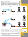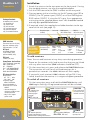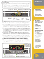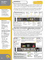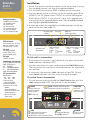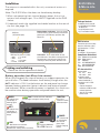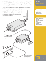
1
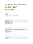
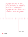
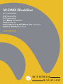
W-DMX BlackBox S-1 transmitter S-2 transmitter T-1 transceiver S-1 Micro transmitter R-512 receiver R-512 Micro & R-512 Micro Lite receivers B-500 & B-1000 boosters user manual wireless solution Welcome W-DMX BlackBox products The W-DMX system lies at the heart of every one of our BlackBox products. W-DMX is specifically engineered by Wireless Solution Sweden AB to provide the same quality, reliability and performance as any hardwired DMX data link. In fact W-DMX gives you greater freedom to create reliable point-to-point and point-tomultipoint installations over large distances. Thank you Thank you for investing in the multi award winning W-DMX system from Wireless Solution Sweden AB. The W-DMX system, as used in all our BlackBox products, allows you to save both time and money on larger indoor and outdoor installations, plus oneoff events where the distance between the console and fixtures is too large. Once again, thanks for investing in W-DMX. Please visit our website and don’t forget to e-mail us your success stories and pictures with W-DMX. All published stories will get a free merchandise kit from Wireless Solution Sweden AB. W-DMX is unique in its use of certain advanced radio techniques which are more often found in mobile phone and military communications. Rather than using fixed frequency channels, W-DMX uses adaptive frequency hopping technology to continually check for interference and to rapidly move operation over to clear radio channels. This occurs one thousand times every second and is used in combination with another advanced technique (called time division multiple access) which makes the most efficient use of every visited frequency channel. The advantage of such technology will quickly become clear to you: consistent and wide ranging control of your lighting systems over potentially great distances. Indeed, you may actually find that it is all too easy to take W-DMX for granted, for two main reasons: • Firstly, the complex communication protocols are fully automated and concealed from view - you just plug-and-play, the BlackBox units do all the hard work. • Secondly, from the DMX connector of one BlackBox unit to the DMX connector of another, the W-DMX system is totally transparent. W-DMX fully adheres to the USITT DMX-512 standard and can justifiably be called a ‘wireless DMX cable’. These are the reasons why in every independent comparison with competing products, BlackBox W-DMX units continually take first prize for distance covered, resilience against interference and ease of installation. For additional information about our technology, please visit our website at www.wirelessdmx.com. IMPORTANT: Don’t forget to register All BlackBox products are covered by a standard 12 month full warranty from the purchase date when you register your products. You can register either at www.wirelessdmx.com or by sending the supplied warranty card to Wireless Solution Sweden AB at the address shown on the rear cover. Overview Point-to-point operation Point-to-point systems are used when you want to send wireless DMX data from a console to a single receiver. As the receiver accepts all 512 DMX channels from the transmitter you can easily daisy chain more fixtures by cable from the original fixture that is wirelessly connected. Tx Rx Rx Tx Rx Point-to-multipoint operation A multipoint W-DMX BlackBox system can support up to 512 individual receivers responding to a single W-DMX BlackBox transmitter. All receivers in a multipoint system will listen only to the designated transmitter and they will all receive the full 512 channels of the DMX universe. This makes it straightforward to connect single fixtures or daisy-chained groups of fixtures to any of the receivers in the system. wireless wired BlackBox S-1 Transmitter Installation 1 Attach the antenna to the connector on the front panel. If using the standard antenna, use also the supplied adaptor. 2 Link the DMX source to the DMX in socket on the rear panel. Package Contents In addition to this manual: 1 pc, BlackBox S-1 1 pc, Power cord 1 pc, DC connector 1 pc, Standard antenna 1 pc, Antenna adaptor 2 pc, Trussholder brackets 3 Connect power to the unit either via the AC power input (90 to 250VAC), the DC power input (12VDC) or via the DMX bypass RJ45 socket (12VDC). If using the AC input, fit an appropriate mains plug to the supplied power cord - this should be carried out only by a qualified electrician. 4 If required, attach the supplied trussholder brackets to the top cover of the unit (see page 12). DC power input (12VDC) Reserved DMX bypass, (XLR female 5pin) DMX in, (XLR male 5pin) DMX Interface Transceivers on bus: 32 (max) Data rate: 250 kbps (max) ESD protection*: ±15 kV AC input 90-250VAC 50/60Hz 1A at 115VAC (max) 0,5A at 230VAC (max) DMX in (RJ45) IMPORTANT AC power input Only one DMX universe input (90-250VAC) may be connected at any time 1: DMX- 2: DMX+ 3: n/c 4: n/c DMX bypass, DC power in 5: n/c 6: n/c 7: Signal GND 8: n/c 1: DMX- 2: DMX+ 3: n/c 4: +12VDC 5: +12VDC 6: n/c 7: Signal GND 8: DC GND DC input To add receivers Compliance declarations 1 Power on the receiver unit(s) and ensure that they are not linked with any other transmitter (LINK indicators should be OFF). 12VDC 1,5A (max) ETSI: EN300 328 & 300 826 EMC: EN301 489-17 CE: EN60950 FCC: UQT-WDXOEMPCBF IC: 6812A-WDMXOEM ARIB:06215559/AA/00 RF characteristics Output power: 20 25** dBm 100 300** mW Frequency range: 2402 to 2479 MHz Channel bandwidth: 1 Sensitivity at 0.1% BER: -95dBm * Slewrate limited for minimum of EMI in unterminated networks. **Only in FCC output power mode. Note: You can add receivers at any time, even during operation. 2 On the transmitter unit, press and release the FUNCTION button. The transmitter will scan for all unlinked receivers for a period of ten seconds - the LINK indicator will flash rapidly. 3 If successful, each receiver’s LINK indicator will go ON. If any failed, check that the receiver is in range and repeat procedure. To unlink all receivers 1 On the transmitter, press and hold the FUNCTION button until LINK begins flashing. All registered receivers will be unlinked. Level Provides indication of radio output signal strength RADIO ON: Indicates that Level display is showing signal strength BATT Not used W-DMX Sweden AB Batt TX Level LINK CTRL DATA POWER Wireless Solution LINK ON: Normal operation FLASH: Unlinking all receivers RAPID FLASH: Linking with receivers TX RX LINK CTRL DATA POWER FUNCTION DATA TX Batt S-1 Sweden AB made in sweden Level FUNCTION RX W-DMX Radio Press and release to search for and link with receivers Wireless Solution made in sweden Radio FUNCTION ON: Transmitting DMX data RX & CTRL Not used POWER ON: Correct power input present BlackBox S-2 Installation Please see left for installation details with the exception of step 2: Transmitter 2 The S-2 unit can simultaneously transmit two separate DMX universes. Link one or two DMX inputs to the two individual DMX in sockets on the rear panel, as required. DC power input (12VDC) Reserved DMX universe 1 in, (XLR male 5pin) DMX universe 2 in (RJ45) AC power input 1: DMX- 5: n/c 2: DMX+ 6: n/c (90-250VAC) 3: n/c 4: n/c 7: Signal GND 8: n/c DMX universe 2 in, (XLR male 5pin) Package Contents In addition to this manual: 1 pc, BlackBox S-2 1 pc, Power cord 1 pc, DC connector 1 pc, Standard antenna 1 pc, Antenna adaptor 2 pc, Trussholder brackets DMX universe 1 in (RJ45) 1: DMX- 2: DMX+ 3: n/c 4: +12VDC 5: +12VDC 6: n/c 7: Signal GND 8: DC GND To add receivers (Set up each universe separately.) Note: You can add receivers at any time, even during operation. DMX Interface Transceivers on bus: 32 (max) Data rate: 250 kbps (max) ESD protection*: ±15 kV 1 For the first DMX universe channel, power on only the receiver units to be used with that universe - ensure that they are not linked with any other transmitter (LINK indicators should be OFF). AC input 2 On the transmitter unit, press and release the FUNCTION button for the appropriate universe channel. The channel will scan for all unlinked receivers for a period of ten seconds - the LINK indicator will flash rapidly. DC input 3 If successful, each receiver’s LINK indicator will go ON. If any failed, check that the receiver is in range and repeat procedure. 4 Now power on the (unlinked) receivers that will be linked with the second DMX universe channel. Follow steps 2 and 3 for the other universe channel to make it search for the receivers. To unlink all receivers from a DMX universe channel 1 On the transmitter, press and hold the appropriate FUNCTION button until LINK begins flashing. All registered receivers linked to that DMX universe channel will be unlinked. FUNCTION W-DMX made in sweden Press and release to search for and link with receivers (for each universe) Wireless Solution Sweden AB Universe 1 Universe 2 FUNCTION LINK DATA LINK FUNCTION DATA CTRL 90-250VAC 50/60Hz 1A at 115VAC (max) 0,5A at 230VAC (max) 12-24VDC 1,5A (max) Compliance declarations ETSI: EN300 328 & 300 826 EMC: EN301 489-17 CE: EN60950 FCC: UQT-WDXOEMPCBF IC: 6812A-WDMXOEM ARIB:06215559/AA/00 RF characteristics Output power: 20 25** dBm 100 300** mW Frequency range: 2402 to 2479 MHz Channel bandwidth: 1 Sensitivity at 0.1% BER: -95dBm * Slewrate limited for minimum of EMI in unterminated networks. **Only in FCC output power mode. CTRL W-DMX Wireless Solution Universe 1 LINK Universe 2 FUNCTION LINK DATA CTRL CTRL LINK (for each universe) ON: Normal operation FLASH: Unlinking all receivers RAPID FLASH: Linking with receivers S-2 TX DATA FUNCTION TX Sweden AB made in sweden DATA (for each universe) ON: Transmitting DMX data CTRL (for each universe) ON: Indicates that W-DMX bus link is active BlackBox T-1 Pro Transceiver Package Contents In addition to this manual: 1 pc, BlackBox T-1 Pro 1 pc, Power cord 1 pc, DC connector 1 pc, Standard antenna 1 pc, Antanna adaptor 2 pc, Trussholder brackets IMPORTANT Only one DMX universe input may be connected at any time Installation Please see page 4 for details. Each T-1 ‘Pro’ can operate either as a transmitter or a receiver. Operation is determined by the MODE button on the rear panel. You can link two T-1 units together in alternate modes, via UTP CAT 5 cabling (using the W-DMX bus port on the rear panel), to operate as repeaters to extend the operational distance. The front panel TX and RX indicators show the current mode for each T-1 unit. Battery button & indicators - Press to change between battery (green indicator) and external power input (red indicator) operation. DC power Reserved input (12-24VDC) DMX out, (XLR female 5pin) DMX in, (XLR male 5pin) DMX Interface AC input 90-250VAC 50/60Hz 1A at 115VAC (max) 0,5A at 230VAC (max) DC input 12V-24DC 1,5A (max) Compliance declarations ETSI: EN300 328 & 300 826 EMC: EN301 489-17 CE: EN60950 FCC: UQT-WDXOEMPCBF IC: 6812A-WDMXOEM ARIB:06215559/AA/00 RF characteristics Output power: 20 25** dBm 100 300** mW Frequency range: 2402 to 2479 MHz Channel bandwidth: 1 Sensitivity at 0.1% BER: -95dBm * Slewrate limited for minimum of EMI in unterminated networks. **Only in FCC output power mode. Mode button - Press to change T1 between transmitter and receiver. See front panel TX & RX indicators for current mode. DMX out, DC power in (see S-1 for pin-out) W-DMX bus port - for connection to another T-1 unit or to a PC. Operation as transmitter Operation as receiver Please see page 4 for details. Please see page 8 for details. When fully charged, the internal battery can support operation for up to 2 hours. Use the button on the rear panel to change between battery operation (green indicator) and external power (red indicator). When no external power is supplied, this switch can be used to cease battery operation and power down the unit. Level Provides alternate indications RADIO of radio signal strength and battery charge ON: Indicates that Level display is show- every two seconds. The RADIO and BATT indicators confirm which function is currently ing signal strength being shown. FUNCTION Operation depends upon current operation mode - see page 4 or page 7 for details BATT ON: Indicates that Level display is showing battery charge W-DMX Wireless Solution Sweden AB made in sweden Radio Batt TX Level FUNCTION RX LINK CTRL DATA POWER W-DMX Wireless Solution Sweden AB made in sweden Radio Level RX MODE TX MODE LINK TX RX LINK CTRL DATA POWER FUNCTION DATA ON: Normal operation FLASH: Unlinking all receivers RAPID FLASH: Linking with receivers ON: Transmitting/ receiving DMX data OFF: Not linked to a transmitter ON: Linked to a transmitter RAPID FLASH: Linking to a transmitter Indicate current operation mode TX/RX T-1 pro TX Batt DMX in (see S-1 for pin-out) AC power input (90-250VAC) RX Transceivers on bus: 32 (max) Data rate: 250 kbps (max) ESD protection*: ±15 kV CTRL ON: Indicates that W-DMX bus link is active POWER OFF: Off or using battery ON: External power input FLASH: Charging battery Installation The antenna is concealed within the unit, no external antenna is required. BlackBox S-1 Micro Transmitter 1 When not operating from internal battery power, the unit requires a low voltage input: 12 to 24VDC supplied via the RJ45 socket. 2 If required, attach the supplied trussholder bracket to the rear of the unit (see page 12). Battery button & indicators - Press to change between battery (green indicator) and external power input (red indicator) operation. DMX in, (XLR male 5pin) Package Contents In addition to this manual: 1 pc, BlackBox S-1 Micro 1 pc, RJ45 power cord 1 pc, Trussholder bracket DMX Interface Transceivers on bus: 32 (max) Data rate: 250 kbps (max) ESD protection*: ±15 kV DC input Fade button - Press to fade off/on the top panel indicators. Note: When running from the internal battery, the indicators fade off automatically to conserve power. DMX in, DC power in (RJ45) 1: DMX- 2: DMX+ 3: n/c 4: +12VDC 5: +12-24VDC 6: n/c 7: Signal GND 8: DC GND Linking and unlinking Battery operation When fully charged, the internal battery can support operation for up to 2 hours. The Level indicators show battery charge when the BATT indicator is ON. Use the button on the end panel to change between battery operation (green indicator) and external power (red indicator). When no external power is supplied, this switch can be used to cease battery operation and power down the unit. RADIO BATT ON: Indicates that Level display is showing battery charge LINK Level Provides alternate indications of radio signal strength & battery charge W-DMX Level Batt ON: Normal operation FLASH: Unlinking all receivers RAPID FLASH: Linking with receivers ETSI: EN300 328 & 300 826 EMC: EN301 489-17 CE: EN60950 FCC: UQT-WDXOEMPCBF IC: 6812A-WDMXOEM ARIB:06215559/AA/00 Output power: 20 25** dBm 100 300** mW Frequency range: 2402 to 2479 MHz Channel bandwidth: 1 Sensitivity at 0.1% BER: -95dBm * Slewrate limited for minimum of EMI in unterminated networks. **Only in FCC output power mode. FUNCTION Press and release to search for and link with receivers Wireless Solution Sweden AB made in sweden Radio Compliance declarations RF characteristics Please see page 4 for details. ON: Indicates that Level display is showing signal strength 12-24VDC 1,5A (max) TX RX LINK CTRL DATA POWER FUNCTION POWER DATA ON: Transmitting DMX data RX & CTRL Not used OFF: Switched off or using battery ON: External power input FLASH: Charging battery BlackBox R-512 Receiver Package Contents In addition to this manual: 1 pc, BlackBox R-512 1 pc, Power cord 1 pc, DC connector 1 pc, Standard antenna 1 pc, Antanna adaptor 2 pc, Trussholder brackets Installation 1 Attach the antenna to the connector on the front panel. If using the standard antenna, use also the supplied adaptor. 2 Link the DMX source to the DMX in socket on the rear panel. 3 Connect power to the unit either via the AC power input (90 to 250VAC), the DC power input (12VDC) or via the DMX bypass RJ45 socket (12VDC). If using the AC input, fit an appropriate mains plug to the supplied power cord - this should be carried out only by a qualified electrician. 4 If required, attach the supplied trussholder brackets to the top cover of the unit (see page 12). DC power input (12VDC) Reserved DMX out, (XLR female 5pin) DMX Interface Transceivers on bus: 32 (max) Data rate: 250 kbps (max) ESD protection*: ±15 kV DMX out (RJ45) AC power input (90-250VAC) AC input 90-250VAC 50/60Hz 1A at 115VAC (max) 0,5A at 230VAC (max) 1: DMX- 2: DMX+ 3: n/c 4: n/c DMX out, DC power in (RJ45) 5: n/c 6: n/c 7: Signal GND 8: n/c 1: DMX- 2: DMX+ 3: n/c 4: +12VDC 5: +12VDC 6: n/c 7: Signal GND 8: DC GND DC input To link with a transmitter Compliance declarations 1 Ensure that this receiver is not linked with any other transmitter (LINK indicator should be OFF). ETSI: EN300 328 & 300 826 EMC: EN301 489-17 CE: EN60950 FCC: UQT-WDXOEMPCBF IC: 6812A-WDMXOEM ARIB:06215559/AA/00 RF characteristics Output power: 20 25** dBm 100 300** mW Frequency range: 2402 to 2479 MHz Channel bandwidth: 1 Sensitivity at 0.1% BER: -95dBm * Slewrate limited for minimum of EMI in unterminated networks. **Only in FCC output power mode. 2 On the transmitter unit, press and release the FUNCTION button. The transmitter will scan for all unlinked receivers for a period of ten seconds. 3 If successful, the receiver’s LINK indicator will go ON. One or more Level indicators will then show the signal strength. To unlink from a transmitter 1 On the receiver, press and hold the FUNCTION button until the LINK indicator goes OFF. The receiver is now unlinked. RADIO Indicates that Level display is showing signal strength BATT Not used Level Provides indication of radio signal strength when linked to a transmitter W-DMX Wireless Solution Sweden AB made in sweden Radio Batt TX Level LINK CTRL DATA POWER Wireless Solution Sweden AB made in sweden Level Batt LINK OFF: Not linked to a transmitter ON: Linked to a transmitter RAPID FLASH: Linking with a transmitter TX RX LINK CTRL DATA POWER Press for 5 seconds to unlink from transmitter FUNCTION RX W-DMX Radio FUNCTION FUNCTION DATA ON: Receiving DMX data TX & CTRL Not used R-512 RX 12VDC 1,5A (max) POWER ON: Correct power input present Installation The antenna is concealed within the unit, no external antenna is required. Note: The R-512 Micro Lite does not have battery backup. 1 When not operating from internal battery power, the unit requires a low voltage input: 12 to 24VDC supplied via the RJ45 socket. 2 If required, attach the supplied trussholder bracket to the rear of the unit (see page 12). Battery button & indicators - Press to change between battery (green indicator) and external power input (red indicator) operation. Not Micro Lite. DMX out, (XLR female 5pin) R-512 Micro & Micro Lite Receiver Package Contents In addition to this manual: 1 pc, BlackBox R-512 Micro or Micro Lite 1 pc, RJ45 power cord 1 pc, Trussholder bracket DMX Interface Transceivers on bus: 32 (max) Data rate: 250 kbps (max) ESD protection*: ±15 kV DC input 12-24VDC 1,5A (maximum) Fade button - Press to fade off/on the top panel indicators. Note: When running from the internal battery, the indicators fade off automatically to conserve power. Not Micro Lite. DMX out, DC power in (RJ45) 1: DMX- 2: DMX+ 3: n/c 4: +12VDC 5: +12-24VDC 6: n/c 7: Signal GND 8: DC GND Linking and unlinking Battery operation (not Micro Lite version) When fully charged, the internal battery can support operation for up to 8 hours. The Level indicators show battery charge when the BATT indicator is ON. Use the button on the end panel to change between battery operation (green indicator) and external power (red indicator). When no external power is supplied, this switch can be used to cease battery operation and power down the unit. RADIO BATT ON: Indicates that Level display is showing battery charge LINK Level Provides alternate indications of radio signal strength & battery charge W-DMX Level Batt OFF: Not linked to a transmitter ON: Linked to a transmitter RAPID FLASH: Linking with a transmitter Output power: 20 25** dBm 100 300** mW Frequency range: 2402 to 2479 MHz Channel bandwidth: 1 Sensitivity at 0.1% BER: -95dBm * Slewrate limited for minimum of EMI in unterminated networks. ** Only in FCC output power mode. FUNCTION Press for 5 seconds to unlink from transmitter Wireless Solution Sweden AB made in sweden Radio ETSI: EN300 328 & 300 826 EMC: EN301 489-17 CE: EN60950 FCC: UQT-WDXOEMPCBF IC: 6812A-WDMXOEM ARIB:06215559/AA/00 RF characteristics Please see left for operational details. ON: Indicates that Level display is showing signal strength Compliance declarations TX RX LINK CTRL DATA POWER FUNCTION POWER DATA ON: Receiving DMX data TX & CTRL Not used OFF: Switched off or using battery ON: External power input FLASH: Charging battery B-500 Signal booster The B-500 is a high performance two way signal amplifier suitable for use with all BlackBox transmitters or receivers (except Micro models) in order to extend transmission range. The B-500 booster unit is for internal use only. To suit varying installation requirements, the B-500 provides variable power outputs, switchable between three levels: 100, 200 and 500mW (27dBm max). Package Contents In addition to this manual: 1 pc, B-500 booster 1 pc, Power adapter Switchable output power levels: 100, 200 & 500mW IN PO Connection to BlackBox unit WE R Power level indicators - according to MODE switch setting Power input from supplied adaptor 5 MODE switch configures power output: 1 = 100mW 2 = 200mW 5 = 500mW 10 2 MO 500mw 100mw Bi-directional TDD technology 200mw 20dB receive gain for the booster 1 DE OU Antenna connector T The B-1000 is a high performance two way signal amplifier suitable for use with all BlackBox transmitters or receivers (except Micro models) in order to extend transmission range within demanding environments. The B-1000 booster unit is fully rated for permanent external installation. The B-1000 is supplied with a power adapter and a DC injector. The latter combines the power input with the antenna signal cable so that power cables do not need to be extended to the location of the B-1000 and antenna. The connectors of both the B-1000 and the DC injector are all female N-type which integrate with most antennae and BlackBox products. B-1000 Signal booster Package Contents In addition to this manual: 1 pc, B-1000 booster 1 pc, DC injector 1 pc, Power adapter Antenna B-1000 booster unit 1000mW (30dBm) output power level To A 20dB receive gain for the booster NT Bi-directional TDD technology Waterproof housing InjeTo D cto C r DC +R Coaxial cable up to 100m with total DC resistance no greater than 0.5 ohm F RF 2V +1 DC DC injector unit Power input from supplied adaptor X DM Win de ma n ede sw el ev io L Rad Batt Coaxial cable link between BlackBox unit and DC injector - up to 100m 11 Trussholders Mounting S-1, S-2, T-1 & R-512 BlackBox units are supplied with trussholder brackets to allow the units to be securely mounted in off-ground locations. Trussholder mounting screws in position 1 Use a Torx® T10 driver to remove the four screws mounted in the top cover of the unit, as shown above (do not remove the screws situated at the four corners). 2 Mount and secure each trussholder bracket so that they are safely held in place, however, take care not to overtighten the screws. on luti B So A ss en ele Swed Wir N CTIO FUN DM W- e in mad X eden sw l ve io Le Rad RX TX LINK L CTR ER POW DATA Batt Trussholder bracket Mounting screw ion lut B So A ss den ele Swe ir W N CTIO FUN X -DM S-1 Micro & R-512 Micro/Micro Lite W 1 Use a Torx® T15 driver to remove the two screws mounted on the rear panel of the unit. 2 Mount and secure the trussholder bracket in any of three rotated positions. Ensure that it is safely held in place, however, take care not to overtighten the screws. 12 den we in s TX LINK RX L CTR ER POW Mounting screws Trussholder bracket Approvals Europe Declaration of Conformity Worldwide We: Wireless Solution, Stureparksvägen 7, 451 55 Uddevalla, Sweden, Tel: +46 522 511 511, declare under our sole responsibility that the products: W-DMX T-1, S-1, S-2, R-512, S-1 Micro, R-512 Micro & R-512 Micro Lite conform to the specifications listed below, following the provisions of the European R&TTE directive 1999/5/EC: • EN 301 489-1, 301 489-17 General EMC requirements for Radio equipment. • EN 609 50 Safety • EN 300-328-1, EN 300-328-2 Technical requirements for Radio equipment. Note: Combinations of power levels and antennas resulting in a radiated power level of above 100 mW equivalent isotropic radiated power (EIRP) are considered as not compliant with the above mentioned directive and are not allowed for use within the European community and countries that have adopted the European R&TTE directive 1999/5/EC. For more details on legal combinations of power levels and antennas, please contact Wireless Solution (see rear cover for contact details). Wireless Solution AB Attn. Mr. N. Norlèn Stureparksvägen 7. 45155 Uddevalla Sweden Date Our reference Your reference Subject : 20 April 2007 : 20071383, Confirmation of notification : : The products are intended to use for controlling of lighting-equipment, trademark W-DMX, models T1, S1, R512, Micro, T2, S2, T1 outdoor, S1 outdoor, T2 outdoor, S2 outdoor, R512 outdoor Dear Mr. N. Norlèn, Herewith we would like to confirm that on April 20 2007, the following products has been notified to the countries Austria, Belgium, Bulgaria, Cyprus, Czech Republic, Denmark, Estonia, Finland, France, Germany, Greece, Hungary, Iceland, Ireland, Italy, Latvia, Liechtenstein, Lithuania, Luxembourg, Malta, The Netherlands, Norway, Poland, Portugal, Romania, Slovakia, Slovenia, Spain, Sweden, Switzerland and the United Kingdom. Manufacturer Description Model Operating frequency Applied standards : Wireless Solution AB : The products are intended to use for controlling of lighting-equipment : T1, S1, R512, Micro, T2, S2, T1 outdoor, S1 outdoor, T2 outdoor, S2 outdoor, R512 outdoor (Trade mark: W-DMX) : 2400 – 2483.5 MHz : EN 300 328-1 V1.3; EN 300 328-2 V1.2.1; EN 301 489-1 V1.7.1; EN 301 489-17 V1.3.1; EN 60950-1 ed. 2 The notifications have been performed on behalf of: Wireless Solution AB Stureparksvägen 7 45155 Uddevalla Sweden Contact person : Mr. N. Norlèn Phone number : +46 522440882 Fax number : +46 522440885 Pursuant to Article 6.4 of the European R&TTE Directive 1999/5/EC, each national authority (responsible for the frequency management) may raise objections against placing the product on the market during a period of 4 weeks after receipt of the notification. The product may be placed on the market if no objection has been received within this period of 4 weeks. Yours sincerely, Mrs. A. Kroon Approval Engineer Telefication B.V. 13 Approvals Worldwide North America Industry Canada Compliance Statement This Class B Digital apparatus meets all the requirements of the Canadian Interference Causing Equipment Regulations ICES 003. Cet appareil numerique de classe B respecte les exigences du reglement du Canada sur le materiel brouilleur. NMB-003. The device is certified to the requirements of RSS-210 for 2.4 GHz spread spectrum devices. The use of this device in a system operating either partially or completely outdoors may require the user to obtain a license for the system according to the Canadian regulations. For further information, contact your local Industry Canada office. TCB TCB GRANT OF EQUIPMENT AUTHORIZATION Certification Issued Under the Authority of the Federal Communications Commission By: Elite Electronic Engineering, Inc. 1516 Centre Circle Downers Grove, IL 60515 Date of Grant: 02/26/2007 Application Dated: 02/26/2007 Wireless Solution Sweden Stureparksvägen 7 SE-451 55 Uddevalla Sweden NOT TRANSFERABLE EQUIPMENT AUTHORIZATION is hereby issued to the named GRANTEE, and is VALID ONLY for the equipment identified hereon for use under the Commission’s Rules and Regulations listed below. FCC IDENTIFIER: UQTWDMXOEMPCBF Solution Sweden Name of Grantee: Wireless Equipment Class: Part 15 Spread Spectrum Transmitter Notes: Grant Notes Wireless Lighting Hardware Interface FCC Rule Parts 15C Frequency Range (MHZ) Output Watts 2402.0 - 2479.0 0.275 Power output is conducted. This device must be installed only by the grantee in their final products with the antennas listed in this filing. This device must not be co-located or operating in conjunction with any other antenna or transmitter. The antenna used for this transmitter must be installed to provide a separation distance of at least 20 cm from all persons. End user and installers must be provided with antenna installation instructions and transmitter operating conditions for satisfying RF exposure compliance. 14 Frequency Tolerance Emission Designator FCC Statment Changes or modifications not expressly approved by the party responsible for compliance could void the user’s authority to operate the equipment. Approvals Worldwide Note: The manufacturer is not responsible for any radio or TV interference caused by unauthorized modifications to this equipment. Such modifications could void the user’s authority to operate the equipment. Declaration of Conformity We: Wireless Solution, Stureparksvägen 7, 451 55 Uddevalla, Sweden, Tel: +46 522 511 511, declare under our sole responsibility that the products: W-DMX T-1, S-1, S-2, R-512, S-1 Micro, R-512 Micro & R-512 Micro Lite comply with Part 15 of FCC Rules. Operation is subject to the following two conditions: (1) this device may not cause harmful interference, and (2) this device must accept any interference received, including interference that may cause undesired operation. To assure continued compliance, any changes or modifications not expressly approved by the party responsible for compliance could void the user’s authority to operate this equipment. Note: This equipment has been tested and found to comply with the limits for a Class B digital device, pursuant to Part 15 of the FCC Rules. These limits are designed to provide reasonable protection against harmful interference in a residential installation. This equipment generates, uses, and can radiate radio frequency energy and, if not installed and used in accordance with the instructions, may cause harmful interference to radio communications. However, there is no guarantee that interference will not occur in a particular installation. If this equipment does cause harmful interference to radio or television reception, which can be determined by turning the equipment off and on, the user is encouraged to try and correct the interference by one or more of the following measures: • Reorient or locate the receiving antenna. • Increase the separation between the equipment and receiver. • Connect the equipment into an outlet on a circuit different from that to which the receiver is connected. • Consult the dealer or an experienced radio/TV technician for help. RF Exposure Warning for North America, and Australia WARNING To meet FCC and other national safety guidelines for RF exposure, the antennas for this device must be installed to ensure a minimum separation distance of 20cm (7.9 in.) from persons. 15 Approvals Worldwide Japan Certificate number: 06215559/AA/00 JP label ID: 201 NY 06215559 Certificate: &HUWLILFDWH RI 5DGLR (TXLSPHQW LQ -$3$1 1R $$ 7HOHILFDWLRQ RSHUDWLQJ DV &RQIRUPLW\ $VVHVVPHQW %RG\ &$% ,' 1XPEHU ZLWK UHVSHFW WR -DSDQ GHFODUHV WKDW WKH OLVWHG SURGXFW FRPSOLHV ZLWK WKH 7HFKQLFDO 5HJXODWLRQV &RQIRUPLW\ &HUWLILFDWLRQ RI 6SHFLILHG 5DGLR HTXLSPHQW RUGLQDQFH RI 037 1 3URGXFW GHVFULSWLRQ 7UDGHPDUN )DPLO\ QDPH 7\SH GHVLJQDWLRQ 6HULDO 1R 6RIWZDUH UHOHDVH 1R 0DQXIDFWXUHU $GGUHVV &LW\ &RXQWU\ :LUHOHVV '0; :'0; %ODFN%R[ 7UDQFLHYHU :LUHOHVV 6ROXWLRQ 6ZHGHQ $% 6WXUHSDUNVYDJHQ 8''(9$//$ 6ZHGHQ 7KLV FHUWLILFDWH LV JUDQWHG WR 1DPH $GGUHVV &LW\ &RXQWU\ :LUHOHVV 6ROXWLRQ 6ZHGHQ $% 6WXUHSDUNVYDJHQ 8''(9$//$ 6ZHGHQ 7KLV FHUWLILFDWH KDV 7+5(( $QQH[HV =HYHQDDU )HEUXDU\ &$% 16 0+ .RRS 0DQDJHU &HUWLILFDWLRQ Is W-DMX compatible with other systems on the market? Today there is no standard for wireless transmission of DMX signals and there is no possibility of mixing different brands of wireless DMX solutions in a system. For example, you cannot use a Martin® Wireless DMX-512 - Pro Diversity® with Interactive Technologies® CueLink® even though they use a similar type of physical radio transmission standard. Because of this, no wireless-DMX brand today is compatible with another. FAQ Questions and answers Is W-DMX built on Bluetooth®? No. It is built on standard radio components with a GSM influenced radio system protocol. Bluetooth® lacks the range needed. Is it plug and play? Yes. W-DMX doesn’t need any configuration for IP address and netmask like WLAN. W-DMX is “plug and play”. Is it made for use outdoors? Yes. Receivers, transceivers, repeaters and boosters are all available in outdoor versions, all with an IP65 rating. What are the differences between the indoor and outdoor models? The outdoor units would use a different antenna. And, of course, the outdoor units are rated IP65 weatherproof. What is IP65? IP65 is a rating of how weather resistant an item is. IP65 means that the device is totally protected against dust and protected against low pressure jets of water from all directions. What is the difference between the standard and the pro models? The pro models of the W-DMX have a built in UPS that will run them for up to 2 hours if power is interrupted. In the future, the pro models will also support ACN and Art-Net, etc. Do the transmitters and receivers have built-in power supplies? All units have built-in universal power supplies that can operate from a supply range of 90-250VAC, 50-60Hz (except the R-512 Micro which requires a 12-24VDC external supply). The pro models of the transmitter and receiver have a built-in UPS that will power them for up to 2 hours if power is interrupted. Will the signal go through solid objects? Yes, the W-DMX signal will penetrate walls, glass, metal and most objects. One thing that will interrupt the signal is people. Antennas should be above audiences to ensure reliable operation. Will other electronics and other W-LAN users interfere with it? No, it is not affected by cell phones. WiFi, W-LAN, bluetooth or any other devices. 17 FAQ Questions and answers How many channels of DMX does it control? Each transmitter can control 512 channels (1 universe) of DMX, unlike some wireless systems which only have “half universe” or 256 channels. The S-2 can additionally control a second DMX universe. What antenna should I use? For most indoor applications the 2 dBi antennas work fine. Longer distances, outdoors or unique applications most likely will require different antennas. Please contact us with your intended application questions. Warranty is voided if using other antennas than W-DMX branded. What is the transmission range? With standard antennas the, maximum distance is 700 m/2300 feet (FCC version). As an option it’s possible to connect other antenna models to achieve longer distances or where there is a specific need for higher gain. (Distances valid at 300 mW FCC) Antenna Transmitter Antenna Receiver Maximum Distance 2 dBi 2 dBi 700 m / 2300 feet 5 dBi 2 dBi 1000 m / 3300 feet 7 dBi 5 dBi 1450 m / 4750 feet 9 dBi 8 dBi 2300 m / 7550 feet How many receivers can be assigned per universe to the W-DMX in a DMX512, DMX512A, or RDM installation? The only limit is the DMX512 standard itself with a maximum of 512 fixtures per universe. Most importantly, this is not done with broadcast techniques (described above). You will always get “talk back” information from the receivers like radio signal strength and much more on a real time basis. If you are using a DMX512A or a RDM network you can still use 512 receivers. Can multiple transmitters run side by side (to support more than one universe)? Yes, up to 8,192 receivers can be controlled from one system, and the standard configuration is with 512 DMX Channels and can easily be updated with 8,192 DMX channels (16 DMX-512 Universes). Do the transmitters & receivers have built in power supplies? All full size units can operate directly from 90-250VAC input or can alternatively run from 12VDC. The Pro and Micro units can run from 12-24VDC. All Pro units and most Micro units also contain battery backup systems to allow sustained operation during power outages. Is it FCC approved? Yes. Please see pages 14 and 15 Is it approved for use in Japan? Yes. Please see page 16 18 Are these products UL Listed? UL pending. What is the typical power consumption? 300mA average, 320mA maximum. Is there a warranty? FAQ Questions and answers All BlackBox products are covered by a standard 12 month full warranty from the purchase date when you register your products. You can register either at www.wirelessdmx.com or by sending the supplied warranty card to Wireless Solution Sweden AB at the address shown on the rear cover. Can the antenna be mounted away from the transmitter or receiver? Yes, there are indoor and outdoor cables available in lengths from 0,5m to 30m (1.6 to 98 feet). Will the receivers stay logged on to the transmitter if the DMX signal is lost? Yes, even if the DMX signal is interrupted the receiver(s) will remain logged in. Will the units stay logged in to each other if power is cut? The log-in information is stored in an EEPROM and will not be erased. No battery backup is needed. In theory, the units stay logged in forever. In an operational system, can I log on an additional receiver without disrupting DMX transmission to other receivers? This is not possible with the BlackBox unit. Logging on an additional receiver will make the logged-in units revert to idle mode for 10 seconds; once the new units are logged-in they will all start again together with the new unit. What is the difference between Multicast and Point to Point? Multi-cast transmitting to multiple receivers simultaneously. Point to Point data is a single path of data transmission. What is FHSS? Short for Frequency Hopping Spread Spectrum - Frequency hopping techniques, in which the transmitter jumps from sub-channel to sub-channel at rapid pace, were first used by the U.S. Military. Such techniques were developed precisely because they are difficult to disrupt and, unless you know the frequency hopping sequence, practically impossible to intercept. Spread spectrum techniques have two main advantages: Firstly, they are more resistant to interference than conventional systems. Secondly, they can be used to provide multiple access functionality. Documentation by: www.ctxd.com Does W-DMX support on-site service with technical documentation after visit? Wireless Solution and/or its distributors offer Cell Planning Service for larger projects. Please contact your local distributor for a quote. This is highly recommended for all larger projects to save time and money. 19 Notes Documentation by: Wireless Solution Sweden AB Stureparksvägen 7 451 55 Uddevalla www.ctxd.com Sweden Phone: +46 522 511 511 Fax: +46 522 440 885 E-mail: [email protected] Web: www.wirelessdmx.com/support Release v3.0g