1
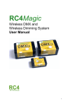
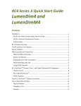
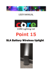
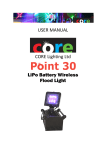
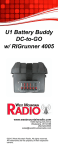
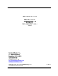
RC4Wireless
TM
W-DIM for W-DMX
User Manual
R1.3
Overview
The RC4Wireless W-DIM for W-DMXTM is a low-voltage DC power 4-channel
wireless dimmer. It communicates with Wireless Solution W-DMXTM transmitters
and other W-DMXTM components. W-DIM is the ideal way to add wireless dimming
to an existing W-DMXTM system, making it easy to put battery-powered lamps,
motors, relays, solenoids, and more, in hand-held props, moving sets pieces, and
other hard-to-reach or mobile positions and locations.
W-DIM will operate with 6V to 30VDC input and provide up to 200W per output
(peak) at 12VDC. W-DIM uses a high-efficiency switching power supply and pwm
(pulse-width-modulation) dimming to provide high output power with minimal heat
and power loss. Dimmer outputs are thermally protected and overload protected.
Under most fault conditions, individual dimmers will disable themselves until the
problem is corrected.
Wireless Solution W-DMXTM Statements of Conformity
1 FCC Statement
DECLARATION OF CONFORMITY
We,
Soundsculpture Incorporated, under the tradename RC4 Wireless,
88 St. George St.,
Etobicoke ON M8Z 3Y7
Canada
declare under our sole responsibility that the product RC4Wireless W-DIM
utilizing the Wireless Solution W-DMXTM OEM RF receiver module:
FCC ID: UQT-WDMXOEMPCBF
Model: W-DMX OEM PCB F
complies with Part 15 of the FCC Rules.
Operation is subject to the following two conditions:
(1) this device may not cause harmful interference, and
(2) this device must accept any interference received, including interference that may cause undesired operation.
To assure continued compliance, any changes or modifications not expressly approved by the party responsible
for compliance could void the user's authority to operate this equipment.
NOTE: This equipment has been tested and found to comply with the limits for a Class B digital device, pursuant
to Part 15 of the FCC Rules. These limits are designed to provide reasonable protection against harmful
interference in a residential installation.
This equipment generates, uses, and can radiate radio frequency energy and, if not installed and used in
accordance with the instructions, may cause harmful interference to radio communications.
However, there is no guarantee that interference will not occur in a particular installation. If this equipment does
cause harmful interference to radio or television reception, which can be determined by turning the equipment off
and on, the user is encouraged to try and correct the interference by one or more of the following measures:
• Reorient or locate the receiving antenna.
• Increase the separation between the equipment and receiver.
• Connect the equipment into an outlet on a circuit different from that to which the receiver is connected.
• Consult the dealer or an experienced radio/TV technician for help.
RF Exposure Warning for North America, and Australia
Warning! To meet FCC and other national safety guidelines for RF exposure, the antennas for this device must
be installed to ensure a minimum separation distance of 20cm (7.9 in.) from persons.
2 Industry Canada Compliance Statement
This Class B Digital apparatus meets all the requirements of the Canadian Interference Causing Equipment
Regulations ICES 003.
Cet appareil numerique de classe B respecte les exigences du reglement du Canada sur le materiel brouilleur
NMB-003.
The device is certified to the requirements of RSS-210 for 2.4 GHz spread spectrum devices. The use of this
device in a system operating either partially or completely outdoors may require the user to obtain a license for
the system according to the Canadian regulations. For further information, contact your local Industry Canada
office.
Disclaimers
WIRING AND INSTALLATION OF BATTERIES, DIMMERS, AND
LOADS MUST BE IN ACCORDANCE WITH APPLICABLE LOCAL
AND NATIONAL ELECTRICAL CODES.
Not for Use Where Human Safety May Be At Risk
RC4 Wireless accepts no liability for direct, indirect, or consequential
damages resulting from the use of any RC4 Wireless product or group of
products. RC4 Wireless does not guarantee the suitability of any product for any
purpose; user assumes all risk. RC4 dimmers must be used strictly in accordance
with manufacturer's instructions and cannot be used for unsupervised operation. RC4
Wireless products must be installed and operated only by qualified technicians and
should be inspected and tested on a regular basis to ensure proper operation.
Not for Control of Pyrotechnical Devices
RC4 Wireless dimmers should not be used to control pyrotechnics of any
kind. A brief output surge during power-up could trigger these devices. RC4
Wireless accepts no liability if RC4 equipment is used for this or any other purpose.
Product Safety
RC4 dimmers are capable of controlling very large currents at up to 30VDC (most
typically 12V or 24V). Dimmers, wiring, and connectors should not be allowed to
operate at dangerous temperatures. Appropriately sized wire and connectors must
be used, along with suitable ventilation and external fuses rated for the load being
operated.
RC4 Wireless devices and equipment are operated at the user’s
own risk and RC4 Wireless accepts no liability, either direct or
consequential, as a result of using this equipment.
W-DIM Hook Up
W-DIM is easy to connect and use. All wiring is done with Anderson Powerpole
connectors. Input power, usually from 12V rechargeable batteries, enters on the
RED+ and BLACK- terminals. Each of the 4 dimmer outputs has a YELLOW+
and GRAY- terminal for direct connection to load devices.
The logic and dimmers in W-DIM will operate with input voltages from 6V to 30VDC.
It is important that the supply voltage does not drop below 6V under full load. If the
voltage dips too low, the logic will restart. This can result in output flicker or
oscillation: the logic comes on, activates the load, the supply voltage drops under
load, the logic goes off, the load is turned off, the voltage rises, the logic comes back
on… and so on.
Maximum output power for each dimmer channel is rated at 200W. The power
devices used are rated for a peak current of 42A, with an on-resistance of just 0.02
ohms. Thus, the theoretical maximum power handling at 12V is over 500W. In
reality, surge currents, heating, and the current carrying capacity of the device leads
and circuit-board traces limit the realistic maximum to something much lower. If the
power devices reach an internal temperature of 150 degrees Celcius, they will
automatically turn off to avoid damage.
Duty cycle also plays a role in determining maximum power. Given the ratings of
the components, a 500W load could be handled for a brief time. But if a load is to be
on for prolonged periods (i.e. hours at a time) then a load of less than 200W is
recommended.
Maximum power handling can be improved with increased ventilation and cooling.
Inversely, if a W-DIM dimmer cannot radiate the heat it produces, it will eventually
overheat and turn itself off. If you find that large loads go off by themselves after a
period of time, this is probably what has happened. In this case, try to improve
ventilation and/or re-orient the dimmer so that the hottest surface faces upward.
Anderson Connectors and Pins
A Blue 15A Fuse Installed
An internal automotive fuse is accessible by removing the bottom cover of the
W-DIM. This fuse is in the positive+ leg of the power circuit. The dimmers deliver
switching power on the negative- leg of the circuit. Thus, higher power levels and
better circuit isolation can be achieved by returning load circuits directly to the
positive+ power supply outside the W-DIM, through appropriate external fuses. In
this case, the yellow+ Anderson terminals are not used.
More information about Anderson connectors is available at
http://www.andersonpower.com/products/singlepole-connectors.html.
If required for your load, you can put a larger fuse value inside the W-DIM, to a
maximum of 40A.
If your loads are small, use smaller fuse values to provide the best circuit
protection. It is also advised to use a safety fuse right at the source battery
terminals. This protects wiring and connectors leading up to the W-DIM, as well as
the W-DIM itself and any connected load wiring.
Controls and Settings
All W-DIM settings and indicators are recessed under holes in the case. Each
dimmer channel has a pushbutton and an LED. There is also a Channel Assign
button, and a W-DMX button.
The W-DMX button works the same way as the Function button on any Wireless
Solution W-DMXTM receiver. Use this button to link the internal W-DMXTM receiver
with your transmitter. Beside the W-DMX button are two W-DMX Status LEDs.
At the back of this manual is a 1-page excerpt from an applicable Wireless
Solution W-DMXTM User Manual, detailing the use of the W-DMX Function
Button and indicator LEDs on W-DMXTM transmitters and receivers. More
information about W-DMXTM is available at http://www.wirelessdmx.com.
You may need to pierce the W-DIM label membrane over the recessed buttons to
access them. A bent paperclip or small screwdriver is ideal for this. Avoid anything
that could drop inside the W-DIM unit, particularly anything made of metal.
The red +V Logic LED indicates that the high-efficiency switching power supply is
delivering 5V power to the internal radio receiver, microprocessor, and dimmer
electronics.
The COP (Computer Operating Properly) LED indicates that the W-DIM
microprocessor is working as it should. In some cases, different modes of operation
are indicated by different blinking speeds and patterns.
The DMX Data LED indicates that the internal W-DMXTM receiver board is producing
valid dmx data packets.
W-DIM Dimmer Test Modes
There are two W-DIM test modes:
Bump Buttons
The button for each dimmer will momentarily turn the dimmer on at 75% when
pressed. The indicator LED will come on, along with the connected load. Use this to
check your wiring, connections, and lamps.
Dimmer indicator LEDs are after the internal fuse and will not light if the
fuse is blown.
Chase Test
Hold the Chan Assign and tap the W-DMX button to put the dimmer into a cycling
chase. Each channel will fade up and down in turn, over and over. Tap the W-DMX
button to stop the chase.
While chasing, the COP (Computer Operating Properly) indicator blinks
rapidly to indicate that level changes are being generated internally and are
not derived from incoming dmx data.
Assigning DMX Channel and Dimmer Curves
Channel setup requires a W-DMXTM transmitter and a DMX data source. You must be
able to bring all DMX channels to zero, and bring up one channel at a time to a
specific level.
A portable Lil’ DMXter or Fleenor Gizmo can be used if your regular console
is inconvenient for this.
When you press the appropriate recessed buttons on the W-DIM, it determines which
channel is currently on, and what level it is at. That channel can be assigned to any
dimmer, and the level of the channel determines which dimmer curve will be used.
Here is the procedure:
1. Zero all DMX channels.
2. Bring up a single channel you wish to assign to a dimmer. When setting the
dimmer, the level of the channel will determine the dimmer curve. There are
three options:
- 0-25% ignored, considered off
- 25% - 49% selects inverse square law for LEDs
- 50% - 74% selects linear curve for incandescent lamps (MR16, etc.)
- 75% - 100% selects non-dim switch mode
3. With the desired channel up at the transmitter, go to the W-DIM receiverdimmer. Press and HOLD the Chan Assign button while momentarily pressing
the button for the dimmer you wish to assign. For example, to assign the
currently active DMX channel to dimmer C, hold Chan Assign and tap the
DimC button. The dimmer will come on when you release the buttons.
That's it – the unit will remember the channel assignment and dimmer curve forever
until you change them.
More About Dimmer Curves
ISL and LEDs
W-DIM pwm dimmers are capable of very high resolution, making them ideal for
smoothly dimming LEDs. To look smooth to the human eye, LEDs must be dimmed
with an Inverse Square Law (ISL) curve, demanding very small changes in level at
the bottom of the curve. At maximum resolution, W-DIM can deliver ISL dimming
with 16,384 steps, so a single step level change represents 0.0061% of full level.
Compare this to standard linear DMX dimmers with 256 steps that each represent
0.3% of full level.
In ISL mode, W-DIM updates pwm levels 1,500 times per second – at 1.5kHz.
Compare this to the 60 Hz power line driving conventional fixtures. This speed is
fast enough to ensure there will be no beating or other unwanted anomalies when
using W-DIM with film or video.
The disadvantage of updating at 1500Hz is that it can be audible. If an incandescent
lamp is used with the highest resolution ISL curve, the filament will noticeably sing.
For the highest possible ISL performance, all 4 W-DIM dimmers must be set
for ISL output.
Linear and Incandescent Lamps
When a linear dimming curve is used with an incandescent lamp, resolution is less
critical, and singing filaments can be annoying. To achieve low lamp noise and high
electrical efficiency, a very low pwm frequency of 75 Hz is used.
For low-frequency near-silent operation, all 4 W-DIM dimmers must be set
for linear output.
Non-Dim
Some loads, including relays, solenoids, and DC-AC power inverters, must be
provided with simple on/off non-dim power. The non-dim output option ensures this,
and includes level hysteresis: the source dmx level must rise about 53% to turn on,
and drop below 47% to turn off. The load will not oscillate on and off if the source
signal is jittery or sitting around 50%.
Non-dim mode is less complicated than pwm dimming and can provide faster
responsiveness. While responsiveness is never a problem in any W-DIM output
mode, the fastest possible routines are used when all 4 W-DIM dimmers are set for
non-dim output.
Mixing ISL and Linear Outputs – A Compromise
Of course, there will be times when a mix of LEDs and incandescent lamps must be
operated from a single W-DIM dimmer. The hardware of the W-DIM requires that all
4 dimmers share the same base frequency and resolution, so a compromise is
required when producing different dimming curves for each dimmer output. In this
case, the low-frequency for linear dimming is used. Be aware that this can cause
LEDs to strobe, or appear to rapidly flicker, and this can cause problems when used
with film or video. This can be avoided by operating all 4 W-DIM channels in ISL
mode.
For optimal performance with different dimmer curves in the same location,
use multiple W-DIM units.
W-DIM Specifications
RF
Frequency Range of operation:
Channel bandwidth:
Sensitivity at 0.1% BER:
FSPL Link range with 5dBi external antenna:
Range with standard 2dBi antenna (measured):
2405 2479 MHz
1 MHz
-96 dBm
3232 m
500 m
Dimmers
Maximum Internal Fuse Current:
40A, fuse rated for 32V or higher
Power Input:
6VDC – 30VDC (12V typical), 50mA minimum, plus
requirements of connected dimmer loads.
Dimmer Outputs:
4 individual dimmer channels, each with independently
assignable DMX channel and dimmer curve.
PWM Resolution:
PWM Frequency (Linear Curve):
PWM Frequency (ISL Curve):
16,384 steps (14-bit)
75 Hz
1.5kHz
Dimmer Technology:
MOSFET PWM (pulse-width-modulation)
Absolute Maximum Output Current per Dimmer:
42A
Absolute Maximum Input Voltage:
30VDC
Typical Continuous Output Current per Dimmer:
18A
Surge Clamping Voltage:
42V
Typical Maximum Continuous Output Power:
Maximum Total Output Power (4 Dimmers Combined)
200W per channel *
500W total *
RELIABLE TOTAL OUTPUT POWER IS LIMITED BY DUTY CYCLE, AMBIENT
TEMPERATURE, AND CIRCUIT-BOARD TRACE SIZE.
User changeable Bussmann ATC load fuse should not exceed 40A and should be
fast-blow type.
* See W-DIM Hook Up section (page 4) for additional information about
power handling and power limits.
How to Reach Us
Physical Address
RC4 Wireless is a registered trade-name of Soundsculpture Incorporated
Soundsculpture Incorporated
(Toronto)
88 St. George St.
(Near Islington & Evans)
Etobicoke ON
Canada M8Z 3Y7
Soundsculpture Incorporated
(Buffalo)
60 Industrial Parkway, #580
Cheektowaga NY
USA 14227
(warehousing only at this location)
Telephone / Fax
Toll Free Office 1-866-258-4577 (North America only)
Toll Free Fax 1-866-237-6641 (North America only)
London, UK, +44 (0)20 3289 8765
Toronto Office 416-259-8499
Emergency Cellular 416-720-5802
Internet
Email [email protected]
Skype theatrewireless
Website www.theatrewireless.com
W-DMXTM is a trademark of Wireless Solution,
used with permission.
RC4, RC4Wireless, and the RC4 logo are trademarks of
Soundsculpture Incorporated.
W-DIM User Manual R1.3 May-2010 JDS