1
TM 9-4910-409-12
DEPARTMENT
OF
THE
OPERATOR
ARMY
AND
AND
DIESEL
NOZZLE
TRIAL
MODEL
MANUAL
REPAIR
SPECIAL
TESTER
TOOL
FUEL
INSTRUMENT
CONNECTOR
PARTS
LISTS)
INJECTOR
(BACHARACH
YFL)
MANUAL
ORGANIZATIONAL
MAINTENANCE
(INCLUDING
TECHNICAL
INDUS-
COMPANY
(4910-255-8641)
SET
44
WITH
(BACHARACH
PART NUMBER 65-275) (4910-955-5517)
AND
CONNECTOR
B11020498)
HEADQUARTERS,
SET
(ORD
DWG
(4910-955-5516)
DEPARTMENT
OF
OCTOBER 1963
THE
ARMY
Changes in force: C1
TM 9-4910-409-12
C1
HEADQUARTERS
DEPARTMENT OF THE ARMY
Washington, D.C., 25 June 1973
Change
No. 1
Operator and Organizational Maintenance Manual
(Including Repair Parts and Special Tool Lists)
TESTER, DIESEL FUEL INJECTOR NOZZLE
(BACHARACH INDUSTRIAL INSTRUMENT COMPANY
MODEL YFL) (4910-255-8641)
WITH CONNECTOR SET 44 (BACHARACH
PART NUMBER 65-275) (4910-955-5517)
AND CONNECTOR SET (ORD DWG B11020498)
(4910-955-5516)
TM 9-4910-409-12, 29 October 1963, is changed
as follows
Page 2. paragraph 1f is superseded as follows
1f. You can improve this manual by calling
attention to errors and by recommending improvements using DA Form 2028 (Recommended
Changes to Publications) or by a letter and
mailing direct to Commander, US Army Weapons Command, ATTN: AMSWE-MAS-SP, Rock
Island IL 61201. A reply will be furnished
direct to you.
Page 3. Add the following to paragraph 4:
Parts included with the end item and considered
as components of the end item configuration
are listed in the following table:
Table 0. Components of the End Item
Components
Part No.
CASE, CARRYING:
65-808
CONNECTOR SET, FUEL INJECTOR 11020498
65-317
CUP, COLLECTOR
65-284
HOSE, PRESSURE, HIGH
(FSCM)
(05083)
(05083)
(05083)
(05083)
Qty
1
1
1
1
Page 22. Appendix II is superseded as follows:
APPENDIX II
BASIC ISSUE ITEMS LIST
AND
ITEMS TROOP INSTALLED OR AUTHORIZED LIST
The basic issue items and items troop installed
or authorized lists are not applicable.
1
By Order of the Secretary of the Army:
CREIGHTON W. ABRAMS
General, United States Army
Chief of Staff
Official:
VERNE L. BOWERS
Major General, United States Army
The Adjutant General
Distribution:
Active Army:
DCSLOG (3)
CNGB (1)
TSG(l)
COE (5)
CONARC (2)
AMC (5)
ARADCOM (2)
ARADCOM Rgn (2)
Armies (3) except
7th USA (5)
8th USA (5)
Corps (2)
OS Maj Comd (2)
LOGCOMD (2)
WECOM (10)
Ft Belvoir (2)
APG(l)
LEAD (2)
LEAD (2)
Instl (2) except
Ft Monmouth (5)
Dir of Trans (1)
USACOMZEUR(l)
Arsenals (1) except
Detroit Arsenal (5)
Units org under fol TOE:
(2 cys each)
7-37
10-500(H-K)
17
29-51
29-56
57
NG: State AG (3)
USAR: None
For explanation of abbreviations used, see AR 310-50.
*U.S.
2
GOVERNMENT
PRINTING
OFFICE
1973-769620/991
TM 9-4910-409-12
Technical Manual
No. 9-4910-409-12
HEADQUARTERS,
DEPARTMENT OF THE ARMY
WASHINGTON 25, D. C., 29 October 1963
OPERATOR AND ORGANIZATIONAL MAINTENANCE MANUAL
(INCLUDING REPAIR PARTS AND SPECIAL TOOL LISTS)
TESTER, DIESEL FUEL INJECTOR NOZZLE
(BACHARACH INDUSTRIAL INSTRUMENT COMPANY
MODEL YFL) (4910-255-8641) WITH CONNECTOR SET 44
(BACHARACH PART NUMBER 65-275) (4910-955-5517)
AND CONNECTOR SET (ORD DWG B11020498)(4910-955-5516)
Paragraph
C HAPTER 1 .
Section
I.
II.
2.
CHAPTER
I.
Section
II.
III.
3.
CHAPTER
Section
I.
II.
111.
IV.
CHAPTER
4.
Section
I.
II.
III.
IV.
V.
VI.
5.
CHAPTER
Section I.
II.
APPENDIX I.
II.
III.
IV.
INDEX ..,...
Page
INTRODUCTION
General . . . . . . . . . . . . . . . . . . . . . . . . . . . . . . . . . . . . . . . . .
1-3
2
Description and data . . . . . . . . . . . . . . . . . . . . . . . . . . . . . . . . .
4-6
3
OPERATING INSTRUCTIONS
7,8
Service on receipt of materiel. . . . . . . . . . . . . . . . . . . . . . . . . . .
5
9-13 5,6
Controls, instruments, and related items . . . . . . . . . . . . . . . . . . . .
14-16
Operation . . . . . . . . . . . . . . . . . . . . . . . . . . . . . . . . . . . . . . . .
6
OPERATOR MAINTENANCE INSTRUCTIONS
9
Repair parts, tools, and equipment . . . . . . . . . . . . . . . . . . . . . . . .
17-20
9
Lubrication . . . . . . . . . . . . . . . . . . . . . . . . . . . . . . . . . . . . . . .
21
9,10
22-24
Preventive-maintenance services . . . . . . . , . . . . . . . . . . . . . . . . .
25-27 11,12
Troubles hooting . . . . . . . . . . . . . . . . . . . . . . . . . . . . . . . . . . . .
ORGANIZATIONAL MAINTENANCE INSTRUCTIONS
28-31
Repair parts, tools, and equipment . . . . . . . . . . . . . . . . . . . . . . . .
13
Painting . . . . . . . . . . . . . . . . . . . . . . . . . . . . . . . . . . . . . . . . .
32
13
Preventive-maintenance services . . . , . . . . . . . . . . . . . . . . . . . . .
33,34
13
35-37 13,14
Troubleshooting . . . . . . . . . . . . . . . . . . . . . . . . . . . . . . . . . . . .
Fuel reservoir assembly . . . . . . . . . . . . . . . . . . . . . . . . . . . . . .
38,39
14
Discharge block assembly and hydraulic pressure gage . . . . . . . . . . .
40,41
16
SHIPMENT AND ADMINISTRATIVE STORAGE AND DEMOLITION
TO PREVENT ENEMY USE
Shipment and administrative storage . . , . . . . . . . . . . . . . . . . . . . .
42-44
17
Demolition of materiel to prevent enemy use . . . . . . . . . . , . . . . . .
45,46 18,19
REFERENCES . . . . . . . . . . . . . . . . . . . . . . . . . . . . . . . . . . . . . . . . . .
20
BASIC ISSUE ITEMS, REPAIR PARTS, AND TOOL LISTS . . . . . . . . . . . . . .
22
MAINTENANCE ALLOCATION CHART . . . . . . . . . . . . . . . . . . . . . . . . . .
27
REPAIR PARTS AND SPECIAL TOOL LISTS . . . . . . . . . . . . . . . . . . . . . .
28
.....................................................
35
1
CHAPTER 1
INTRODUCTION
Section I.
1. Scope
a. This technical manual contains instructions on operation and maintenance
of the diesel fuel injector nozzle tester
for the operator and instructions for organizational maintenance of the nozzle
tester by personnel of the using organization.
b. Appendix I contains a list of current
references, including supply manuals,
forms, technical manuals, and other available publications applicable to the nozzle
tester.
c. Appendix II contains a list of equipment and tools which are required by the
operator for operating and maintaining the
nozzle tester.
d. Appendix III contains the maintenance
allocation chart for the nozzle tester listing all maintenance and repair operations
authorized for all maintenance echelons.
e. Appendix IV contains a list of repair
parts which are required by the using organization for performing organizational
maintenance on the nozzle tester.
f. The direct reporting of errors, omissions and recommendations for improving
this equipment manual by the individual
user, is authorized and encouraged. DA
Form 2028 will be used for reporting these
improvements. This form may be completed using pencil, pen or typewriter.
DA Form 2028 will be completed in triplicate and forwarded by the individual using
the manual. The original and one copy will
be forwarded direct to:
Commanding General
Headquarters, U. S. Army Weapons
Command
ATTN: AMSWE-SMM-TE
Rock Island Arsenal
Rock Island, Illinois 61202
One information copy will be provided to
the individual’s i m me d i a t e supervisor
2
GENERAL
(e. g. officer, noncommissioned officer,
supervisor, etc.).
2. Maintenance Allocation
a. Operator Maintenance Allocation. The
prescribed maintenance to be performed
by the operator will apply as reflected in
the operator-maintenance (first echelon)
column of the maintenance allocation chart
(app. III). In all cases, where the nature of
the repair, modification, or adjustment is
beyond the scope or facilities of the operator, organizational-maintenance personnel should be informed so that trained
personnel with suitable tools and equipment may be provided or other instructions issued.
b. Organizational Maintenance Allocation. The prescribed maintenance to be
performed by maintenance personnel of the
using organization will apply as reflected
in the organizational-maintenance (second
echelon) column of the maintenance allocation chart (app. III). In all cases where
the nature of the repair, modification, or
adjustment is beyond the scope or facilities of the using organization, the supporting maintenance unit should be informed
so that trained personnel with suitable
tools and equipment may be provided or
other instructions issued.
3. Farms, Records, and Reports
a. General. Responsibility for the
proper execution of forms, records, and
reports rests upon the officers of all units
maintaining this equipment. However, the
value of accurate records must be fully
appreciated by all persons responsible for
their compilation, maintenance, and use,
Records, reports, and authorized forms
are normally utilized to indicate the type,
quantity, and condition of materiel to be
inspected, to be repaired, or to be used in
repair. Properly executed forms convey
authorization and serve as records for
repair or replacement of materiel in the
hands of troops and for delivery of materiel requiring further repair to shops in
arsenals, depots, etc. The forms, records,
and reports establish the work required,
the progress of the work within the shops,
and the status of the materiel upon completion of its repair.
b. Authorized Forms. The forms generally applicable to units operating or
maintaining this materiel are listed in
appendix I. For a listing of all forms, refer
to DA Pam 310-2. For instructions on use
of these forms, refer to FM 9-3 and TM
38-750.
c. Equipment Improvement Recommendations. Any deficiencies detected in the
equipment covered herein which occur
under the circumstances indicated in AR
750-5, should be immediately reported in
accordance with the applicable instructions in cited regulation.
d. Field Report of Accidents. The report necessary to comply with the requirements of the Army safety program are
prescribed in detail in AR 385-40. These
reports are referenced whenever accidents involving injury to personnel or damage to materiel occur.
Section Il. DESCRIPTION AND DATA
4. Description
5. Data Plate
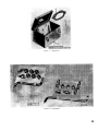
The nozzle tester (fig. 1) is an instrument used for analyzing and testing the
accuracy of diesel engine injector nozzles
for opening pressure, spray p a t t e r n,
chatter, and leakage. It consists of a hydraulic pressure gage, fuel reservoir assembly, discharge block assembly, and
body and plunger assembly. The fluid used
for testing nozzles is contained in the fuel
reservoir assembly. The flow of the fluid
is maintained by the pressure developed
through the action of the body and plunger
assembly and is controlled by the discharge block assembly, The pressure developed during the various tests is indicated on the hydraulic pressure gage. The
nozzle tester is contained in a metal carrying case with all necessary accessories,
equipment, and instruction handbook.
The nozzle tester has one data plate (3A,
fig. 1) which is located on the discharge
block assembly (3, fig, 1). This plate specifies the manufacturer’s name, address,
and code number.
6. Tabulated Data
Manufacturer . . . . . Bacharach Industrial Instrument
Company
Model . . . . . . . . . . YFL
Length . . . . . . . . . . 12 in.
Width . . . . . . . . . . 10 in.
Height . . . . . . . . . . 7-1/2 in.
Cubage (w/equipment)
packaged . . . . . . . .999 tuft
Weight (w/equipment)
packaged . . . . . . .24lb
3
l–Fuel reservoir assembly
A–Fuel reservoir
B–Center rod assembly
C–Fuel reservoir cover
2–Hydraulic pressure gage
3–Discharge block assembly
A–Data plate
B–Valve handle
C–Hydraulic pressure gage
valve assembly
D–Upper discharge outlet
E–Lower discharge outlet
F–Cap nut assembly
4–Body and plunger assembly
A–Handle shoe
B–Pump handle assembly
C–Vent screw
Figure 1. Nozzle tester.
CHAPTER 2
OPERATING INSTRUCTIONS
Section I. SERVICE UPON RECEIPT OF MATERIEL
7. Purpose
a. When a new or reconditioned nozzle
tester is first received, it is the responsibility of the officer in charge to determine
whether the materiel has been properly
prepared for service by the supplying organization and to be sure it is in condition
to perform its function. For this purpose,
inspect all assemblies and parts to be sure
they are properly assembled, secured,
cleaned, adjusted, and/or lubricated.
b. Make a record of any missing parts,
tools, and/or equipment, and any malfunctions. Correct any deficiencies as quickly
as possible.
8. Services
a. Unpacking and Checking. Pry off the
top of the exterior container and turn the
container upside down letting the nozzle
tester slide out of the container, Remove
the barrier material enveloping the nozzle
tester and all cushioning materials, seals,
and wrappings from the case of the nozzle
tester, also, all equipment stored in the
case. Check all equipment with the listing
in appendix II to be sure every item is
present and in good condition.
b. Cleaning. Remove all preserving materials and clean all parts of the nozzle
tester, and equipment as prescribed in
paragraph 23.
c. Lubrication. The nozzle tester requires no lubrication.
d. Inspection.
(1) Perform a general inspection of the
nozzle tester to assure that all
parts are properly and securely
assembled and in good condition
(par. 22 b).
(2) Perform the preventive-maintenance services as prescribed in
table I, paragraph 24.
(3) Operate the nozzle tester (pars.
15 and 16) and check to see if the
components are functioning properly by checking such items as
hydraulic pressure gage, body and
plunger assembly, etc.
Section Il. CONTROLS, INSTRUMENTS, AND RELATED ITEMS
Note: The key numbers shown below in parentheses in this section refer to figure 1 except where otherwise indicated.
9. General
This section describes, illustrates, and
furnishes the operator with sufficient information pertaining to the various controls, instruments, and related items for
the proper operation of the nozzle tester.
10. Fuel Reservoir Assembly
The fuel reservoir (1A) contains the test
fluid used to conduct tests when checking
the performance of fuel injector nozzles;
The fuel reservoir has a built in paper
type filter element (2D, fig. 3). The test
fluid is forced through the filter element
by atmospheric pressure and pump suction.
11. Hydraulic Pressure Gage Valve
Assembly
The hydraulic pressure gage valve assembly (3C) stops the flow of the test fluid
to the hydraulic pressure gage. Turn the
valve handle (3B) left to open and right to
close.
5
12. Hydraulic Pressure Gage
13. Pump Handle Assembly and Handle Shoe
The hydraulic pressure gage (2) indicates the amount of pressure applied
when testing the various types of nozzles.
The dial has a range of O to 5,000 psi
(pounds per square inch) and marked in
increments of 50 psi.
The action of the pump handle assembly
(4B) and handle shoe (4A) actuates the
plunger built within the body and plunger
assembly (4), and producing a hydraulic
pressure which is recorded on the hydraulic pressure gage (2).
Section Ill. OPERATION
Note: The key numbers shown below in parentheses in this section refer to figure 1.
14. General
This section contains instructions for the
operation of the nozzle tester under conditions of moderate temperatures and humidity. Every organization equipped with
this item must thoroughly train its personnel in the procedures for operating
this item.
15. Preparation for Operation
a. Mount the nozzle tester (fig. 1) on a
bench and secure with three 3/8-inch bolts,
washers, and nuts. For portable use, mount
on wooden or metal base 5 inches wide x
15 inches long. Use 3/4-inch plywood or
l/2-inch sheet steel.
b. Slide the pump handle assembly (4B)
onto the handle shoe (4A) located in the
base of the nozzle tester. Solid shaft in the
pump handle assembly may be extended or
telescoped, depending on 1 e v e r a g e required.
c. Remove the fuel reservoir cover (lC)
from the fuel reservoir (1A) with a combined twisting and pulling motion. Fill the
fuel reservoir with test fluid and install
the fuel reservoir cover.
d. Open the valve handle (3B) and make
several strokes with the pump handle assembly (4B) to prime the nozzle tester.
Close the valve handle.
Note. A vent screw (4C) is located on the side of
the housing behind the lower discharge outlet (3E)
and can be opened for thorough venting and priming
if necessary.
16. Operation
a. Discharge Block Assembly. The dis6
charge block assembly (3) has two discharge outlets to facilitate the various
tests. When nozzle under test is connected
to lower discharge outlet (3E) and with
hydraulic pressure gage valve assembly
(3C) closed, this shuts off and protects the
hydraulic pressure gage (2) during rapid
and prolonged pumping periods when flushing nozzle or observing spray form. Using
upper discharge outlet (3D) and closing
hydraulic pressure gage valve assembly
(3C) isolates hydraulic pressure gage (2)
and the nozzle under test from the nozzle
tester (fig. 1) permitting leakage rates or
pressure drop measurement tests.
Note. Install and tighten cap nut assembly (3F) on
discharge outlet not in use.
b. Mounting Instructions. Mount the fuel
injector nozzle to be tested on the nozzle
tester in accordance with the connecting
instructions (fig. 2) using connector set
4910-955-5517 (1, fig. 6).
Note. C o n n e c t o r s e t 4 9 1 0 - 9 5 5 - 5 5 1 6 ( 2 , f i g . 6 ) i s
connected in a similar manner as connector set
4910-955-5517 (1, fig. 6).
c. Testing Nozzles.
(1) General. For the v a r i o us tests,
connect the nozzle to the discharge
outlets, as prescribed in (2), (3),
(4) and (5) below. Use the spray
collector cup (2, fig. 5) for catching the test fluid. For best results,
tip of nozzle should be well centered in the cup.
Warning: Be careful of the penetrating power of the atomized test
fluid under pressure as it is sufficient to puncture the skin permitting test fluid to enter wound and
INSTRUCTIONS
CONNECTOR SET 44
BACHARACH PART NO. 65-275
Figure 2. Connecting instructions.
7
may cause blood poisoning. Keep
hands free of spray at all times.
(2) Opening Pressure. Use lower discharge outlet (3E). Open the hydraulic pressure gage valve assembly (3C), operate the pump
handle assembly (4B) slowly and,
when nozzle begins to spray test
fluid, observe the pressure indicated on the hydraulic pressure
gage (2). This pressure should be
compared with that specified by the
engine manufacturer and nozzle
adjusted, if necessary, before proceeding with further testing. Test
should be repeated several times
to be certain that nozzle consistently opens at the same pressure
each time.
(3) Spray Pattern. Use lower discharge outlet (3E). Close the hydraulic pressure gage valve assembly (3C) and operate the pump
handle assembly (4B) at approximately 15 strokes per minute.
Make sure that all spray holes are
open and are spraying the same
amount of test fluid. The spray
formation should be sharp with a
rather solid pattern and the angles
formed by the individual sprays
should be uniform. A missing section or uneven spray pattern indicates clogged or eroded orifices.
8
Sample spray patterns are generally shown in the engine manual.
(4) Chatter. Use lower discharge outlet (3E). Close the hydraulic pressure gage valve assembly (3C) and
operate the pump handle assembly
(4B) approximately two seconds.
The nozzle chatter must be distinct
and regular. A sharp pitch sound
is not mandatory, and an occasional skip or variation in the
chatter sound pitch is acceptable.
When nozzle chatter is not satisfactory and does not improve with
continued operation of the pump
handle assembly, replace the nozzle.
(5) Leakage. Use lower discharge outlet (3E). Open the hydraulic pressure gage valve assembly (3C) and
opera t e pump handle assembly
(4B). During prolonged pumping,
drops of test fluid should not form
at tip of the nozzle. A second check
for leakage can be made by maintaining pressure just below opening
pressure and checking for test fluid
leakage from tip. If this test is to
be used, reconnect nozzle to upper
discharge outlet (3D) and close the
hydraulic pressure gage valve assembly (3C) to time pressure drop.
Some manufacturers specify permissible leakage rates.
CHAPTER 3
OPERATOR MAINTENANCE INSTRUCTIONS
Section I. REPAIR PARTS, TOOLS, AND EQUIPMENT
17. General
19. Common Tools and Equipment
Repair parts, tools, and equipment are
issued to the operator for operating and
maintaining the nozzle tester. Tools
and equipment should not be used for
Purposes other than prescribed and
when not in use should be properly
stored.
Common tools and equipment having general application to this materiel are
authorized by tables of allowances and tables of organization and equipment.
18. Repair Parts
No repair parts are supplied to the operator for replacement of those already on
the nozzle tester.
20. Special Tools and Equipment
No tools specially designed for operation
or operator maintenance are supplied or
required for the nozzle tester. Equipment
supplied is listed in appendix II, which is
the authority for requisitioning replacement.
Section Il. LUBRICATION
21.
Lubrication
No lubrication is required on the nozzle tester.
Section Ill. PREVENTIVE-MAINTENANCE SERVICES
22. General
a. Responsibility and Intervals. The
primary function of preventive maintenance is to prevent breakdown and,
therefore, the need for repair. These services consist generally of before operation
and after-operation services performed by
the operator. Intervals are based on normal operations, Reduce intervals for abnormal operations or severe conditions.
Intervals during inactive periods may be
extended accordingly.
b. Definition of Terms. The general inspection of each item applies also to any
supporting member or connection and is
generally a check to see whether the item
is in good condition, correctly assembled,
secure and not excessively worn:
(1) The inspection for “good condition”
is usually an external visual inspection to determine whether the
unit is damaged beyond serviceable
limits by the following not bent or
twisted, not chafed or burred, not
broken or cracked, n o t bare or
frayed, not dented or colIapsed, not
torn or cut, not deteriorated.
(2) The inspection of a unit to see that
it is “correctly assembled” is usually an external visual inspection to
see whether it is in its normal assembled position.
(3) Inspection of a unit to determine if
it is “secure” is usually an external
visual examination or an examination by hand or wrench for looseness. Such an examination must include any brackets, lockwashers,
9
lock nuts, locking wires, or cotter
pins used.
(4) By “excessively worn” is me ant
worn beyond serviceable limits or
to a point likely to result in failure
if the unit is not replaced before
the next scheduled inspection.
23. Cleaning
a.. General. Any special cleaning instructions required for specific components or parts are contained in the pertinent section. Cleaning instructions are as
outlined in (1) and (2) below. General cleaning precautions are contained in b below.
(1) Metal parts.
(a) Use self-emulsifying decreasing
solvent compound, mineral spirits paint thinner, or dry-cleaning
solvent (Stoddard) to clean or
wash grease or oil from all metal
parts of the nozzle tester.
(b) Use clean water or a solution of
either 1/4 pound of soap chips or
six ounces of painted-surface detergent to one gallon of hot water
for all parts and overall general
cleaning of painted surfaces.
(c) After parts are clean, dry them
thoroughly. Apply a light film of
special preservative lubricating
oil to all parts having a polished
surface to prevent misting.
(d) Before installing new parts, remove any rust-preventive compound, protective grease, etc.
(2) Rubber Parts Other Than Electrical. Clean rubber parts with soap
and warm water. Apply a coating of
powdered technical talcum to preserve the rubber.
b. General Precautions in Cleaning.
(1) Self-emulsifying decreasing solvent compound, mineral spirits
paint thinner, and dry-cleaning
solvent are flammable and should
not be used near an open flame.
Fire extinguishers should be provided when these materials are
used Use only in well-ventilated
places. These cleaners evaporate
10
quickly and have a drying effect
on the skin. If used without
gloves, they may cause cracks
in the skin and, in the case of
some individuals, a mild irritation or inflammation.
(2) Avoid getting petroleum products,
such as mineral spirits paint
thinner, dry-cleaning solvent, engine fuels, or lubricants, on rubber parts, as they will deteriorate the rubber.
(3) The use of Diesel fuel oil, gasoline, or benzene (benzol) for
cleaning is prohibited.
c. Rust Removal. Remove rust or corrosion from all parts of the materiel.
To remove rust or corrosion from unfinished surf aces, use steel cleaning
brushes or abrasive cloth. On finished surfaces, other than highly polished surfaces, remove rust or corrosion by
buffing with a rotary wheel wire brush
constructed of steel wire between 0.010
and 0.025 inch in diameter. Crocus cloth
may be used manually to remove rust
or corrosion from polished surfaces.
24.
Operator’s
Services
Preventive-Maintenance
a. Purpose. To insure efficient operation, it is necessary that the nozzle tester be systematically inspected at intervals each day it is operated so defects
may be discovered and corrected before
they result in serious damage or failure. Certain scheduled maintenance services will be performed at these designated intervals. The correction of any
defect or unsatisfactory operating characteristics beyond the scope of the operator must be reported at the earliest
opportunity to organizational maintenance personnel for correction (pars. 33
through 41).
b. Services. Operator’s preventivemaintenance services are listed in table I. Every operator equipped with the
nozzle tester must be thoroughly familiar with maintenance procedures for
this materiel.
Table I. Preventive Maintenance Checks
and Services
1st Echelon
Daily Schedule
Item to be
inspected
Paragraph
reference
Procedure
Nozzle tester & Clean hydraulic
pressure gage
by wiping dirt
and other
foreign matter from
ridges and
surface of
gage face.
b. Clean accumulation of dirt
and other
foreign matter from
outside surface of the
fuel reservoir assembly.
c. Clean the accumulation of
dirt and other
foreign matter from interior surfaces of the
body and
plunger assembly at
point of handle entrance
in handle
shoe.
Inspect painted
surfaces for
chips, peeling,
and other such
defects.
Notify organizational
maintenance
personnel if
surfaces re-
Par. 23
see fig. 1
Par. 23
see fig. 3
Par. 23
see fig. 3
Table I. Preventive Maintenance Checks
and Services — Continued
1st Echelon
Item to be
inspected
Daily Schedule
Procedure
quire refinishing.
Equipment -- a. Wipe dirt or
other foreign
matter from
inside and
outside of
carrying case.
----------- b. Straighten distorted or bent
fasteners and
aline with
catches on
cover of
carrying case.
----------- c. Clean accumulation of dirt
and other
foreign matter from high
pressure hose.
d. Clean accumulation of dirt
and other
foreign matter from all
components of
the connector
sets and replace on the
mounting
plates.
e. Clean accumulation of dirt
and other
foreign matter from the
spray collector cup.
f. Store all equipment in
carrying case,
Paragraph
reference
See fig. 5
See fig. 5
Par. 23
see fig. 5
See fig. 6
Par. 23
see fig. 5
See fig. 5
Section IV. TROUBLESHOOTING
25. Purpose
Troubleshooting is a systematic determination of malfunctions and defective
components by indications, symptoms,
and tests. Close adherence to the procedures covered herein will materially
reduce the time required to locate
trouble and restore the materiel to normal operation.
Caution: Operation of the nozzle tester
w i t h out preliminary examination can
cause further damage to a disabled component. Be careful during inspection and
troubleshooting, so that damage can be
avoided.
26. Scope
This section covers troubleshooting
11
which is peculiar to the operator’s
(first echelon) maintenance operations.
Table II. Troubleshooting – Continued
Malfunction
27. Procedure
Malfunctions which may occur with
the nozzle tester are listed in table
II. Upon observing any one of these
malfunctions, take immediate steps to
locate and correct the cause. Causes
are listed opposite each malfunction
and are arranged according to the ease
of correction.
Table II. Troubleshooting
Malfunction
Probable
cause
1. Test fluid
starvation.
a. Hydraulic pres2. Unable to
sure gage not
build up
threaded tighthydraulic
ly into dispressure
charge block
on hydrausub-assembly
lic pressure gage
Gage valve
(2, fig. 1).
assembly not
threaded tightly into discharge block
sub-assembly
12
Corrective
action
a. Refer malfunc tion to
organizational maintenance personnel for
correction.
a. Tighten hydraulic pressure
gage farther
into discharge block
subassembly
(fig. 4).
b. Tighten gage
valve assem bly farther
into discharge
block subassembly
(fig. 4).
3. Indications
of test
fluid leakage at
plunger of
body and
plunger
(1-A, fig.
3).
Probable
cause
Corrective
action
c. Socket head cap c. Tighten socket
head cap
screws loose
screws farin discharge
ther into disblock subcharge block
assembly.
sub-assembly
(4, fig. 3).
d. Tighten connecd. Loose connection and cap
tion to either
nut assembly
the upper or
on discharge
lower disoutlets.
charge outlet
(3-D, and
3-E, fig. 1) 01
cap nut
assembly
(3-F, fig. 1),
not tight on
discharge
outlet not in
use.
e. Other causes -- e. Refer other
causes to
organizational maintenance personnel for
correction.
Refer malfunction to
organizational maintenance personnel for
correction.
CHAPTER 4
ORGANIZATIONAL MAINTENANCE INSTRUCTIONS
Section I REPAIR PARTS, TOOLS, AND EQUIPMENT
28. General
Repair parts, tools, and equipment over
and above those available of the operator
are supplied by the using organization for
maintaining the nozzle tester. Tools and
equipment should be properly stored when
not in use.
29. Repair Parts
Repair parts are supplied to the using
organization for replacement of those
parts most likely to become worn, broken,
or otherwise unserviceable, provided that
replacement of these parts is within the
scope of organizational maintenance funcSection Il.
32. Painting
Instructions for the preparation of the
materiel for painting, methods of painting,
Section
Ill.
tions. Repair parts supplied for organizational maintenance of the nozzle tester are
listed in appendix IV.
30. Common Tools and Equipment
Common tools and equipment having general application of this materiel are authorized by tables of allowances and tables
of organization and equipment.
31. Special Tools and Equipment
No tools or equipment specially designed
for organizational maintenance are supplied or required for the nozzle tester.
PAINTING
as well as a list of materials to be used
are contained in TM 9-213. Materials for
painting are listed in appendix IV.
PREVENTIVE-MAINTENANCE
33. General
Refer to section III of chapter 3 for
preventive-maintenance services for the
operator. These instructions apply equally
to maintenance personnel of the using organization.
SERVICE
34. Organizational Preventive-Maintenance
Services
No further preventive-maintenance
services beyond that prescribed for the
operator is required of maintenance personnel of the using organization.
Section IV. TROUBLESHOOTING
35. Purpose
Troubleshooting is a systematic determination of malfunctions and defective
components by indications, symptoms, and
tests. Close Adherence to the procedures
covered herein will materially reduce the
time required to locate trouble and restore
the materiel to normal operation.
Caution: Operation of materiel without
a preliminary examination can cause fur13
ther damage to a disabled component. Be
careful during inspection and troubleshooting, so that damage can be avoided.
36. Scope
This section covers troubleshooting
which is peculiar to organizational (second
echelon) maintenance operations. For
troubleshooting procedures performed by
the operator, see paragraphs 25 through
27.
37. Procedure
Malfunctions which may occur with the
nozzle tester are listed in tables II and
III. In effect, table III is the continuation
of table II, paragraph 27. Causes are listed
opposite each malfunction and are arranged according to the ease of correction.
Table III. Troubleshooting
Probable
Malfunction
1. Test fluid
starvation
Corrective
cause
action
a. Replace filter
element
(par. 39).
b. Discard old
O-rings,
seal, or
gaskets and
replace with
new parts
(par. 39).
c. Other causes -- c. Refer other
causes to
field
maintenance e per-
a. Filter element
dirty or
plugged up.
b. Leaking Orings, seal,
or gaskets of
filter assembly.
Table III. Troubleshooting – Continued
Malfunction
Probable
cause
Corrective action
sonnel for
correction.
a. Discard old
2. Unable to
a. Defective gasgasket and
build up
ket on gage
replace with
hydraulic
valve
new gasket
pressure
assembly.
(par. 41).
on hydraub. Dirt accumula- b. Clean dirt from
lic presdischarge
tion in dissure gage
charge block
block assem(2, fig. 1).
bly (2, fig. 4).
assembly.
c. Defective valve c. Discard old
valve gasket
gasket or Oring in disand O-ring
and replace
charge block
with new
assembly.
gasket and
O-ring (par.
41).
d. Scratched or
d. Replace valve
scored valve
seat (par.
41).
seat.
e. Replace with
e. Defective
new hydrauhydraulic
lic pressure
pressure
gage (par.
gage.
41).
f. Other causes -- f. Refer other
causes to
field maintenance personnel for
correction.
Refer malfunc3. Indications
tion to field
of test
maintenance
fluid leakpersonnel for
age at
correction.
plunger of
body and
plunger
(l-A, fig.
3).
Section V. FUEL RESERVOIR ASSEMBLY
Note. The key numbers shown below in parentheses in this section refer to figure 3.
38. Description
The fuel reservoir assembly (2) is
mounted on t o p of the body and plunger
assembly (1) and consists primarily of a
reservoir (2B), cover (2J), center rod assembly (2G), and filter element (2D). The
reservoir assembly can be removed from
the body and plunger assembly by taking
the cover off the reservoir and unscrewing the center rod assembly. Test fluid
used for testing the performance of fuel
injector nozzles is stored in the reser14
voir. The fluid is forced through the filter
element to remove impurities.
39. Maintenance
a. General. Organizational personnel
has the authorization for the complete
maintenance of the fuel reservoir assembly to the extent of removing, disassembling for inspection and replacement of all
unserviceable components, and the final
steps of assembling and installing the assembly.
b. Disassembly. Remove the cover (2J)
from the reservoir (2B) by using a combined twisting and pulling motion. Unscrew
the center rod assembly (2G) from the body
and plunger assembly (1) and remove the
O-ring (2H). Slide the filter element (2D),
filter washer (2E), and filter spring (2F)
off the center rod assembly (2G). Remove
the upper and lower filter gaskets (2C)
from the filter element. Remove the reservoir (2B) from the body and plunger assembly (1) and the seal (2A) from the
reservoir.
c. Cleaning. Clean the parts thoroughly
with an appropriate solvent (par. 23).
d. Inspection and Repair.
(1) inspect the cover (2J), O-ring (2H),
reservoir (2B), center rod assembly (2G), filter spring (2F), filter
washer (2E), upper and lower
1 - Body and plunger assembly
A–Body and plunger
B–Handle
2 - Fuel reservoir assembly
A - Seal
B - Reservoir
C - Upper and lower gasket
D - Filter element
gaskets (2C), and seal (2A) for
being in good condition (par. 22b).
(2) Replace with new, the filter element (2D) and all other parts determined not in good condition.
e. Assembly. Install the seal (2A) on
the bottom of the reservoir (2B) and mount
the reservoir on top of the body and
plunger assembly (1). Slide the filter
spring (2F), filter washer (2 E), and O-ring
(2H) onto the center rod assembly (2G).
Place the upper and lower gaskets (2C) on
the filter element (2D) and slide the filter
element onto the center rod assembly (2G).
Screw the center rod assembly into the
body and plunger assembly (1). Install the
cover (2J) on the reservoir (2B).
Note. One end of the filter element is red and
marked “top”. Be sure the element is installed
with this end in the upward position.
E - Filter washer
F - Filter spring
G - Center rod assembly
H - O-ring
J - Cover
3 - Discharge block assembly
and hydraulic pressure gage
4 - Socket head cap screw
Figure 3. Fuel reservoir assembly,
15
Section VI. DISCHARGE BLOCK ASSEMBLY AND HYDRAULIC PRESSURE GAGE
N o t e . The key numbers shown below in parentheses in this section refer to figure 4 except where otherwise indicated.”
40. Description
The discharge block assembly and hydraulic pressure gage (3, fig. 3) is mounted
on the front of the body and plunger assembly (1, fig. 3) and can be removed by
unscrewing four socket head cap screws
(4, fig. 3). It consists primarily of a cap
nut assembly (2E), discharge block subassembly (2F), gage valve assembly (2H)
with handle (2J), filler rod assembly (2B),
valve seat (2C), and hydraulic pressure
gage (1). The flow of test fluid from the
reservoir assembly (2, fig. 3) is controlled
by the discharge block assembly by opening
and closing the gage valve assembly (2H).
41.
Maintenance
a. General. Organizational
personnel
has the authorization for the complete
maintenance of the discharge block assembly and hydraulic pressure gage to the
extent of removing, disassembling for
inspection and replacement of all unserviceable components, and the final steps of
assembling and installing the assembly
and gage.
h. Removal. Unscrew the four socket
head cap screws (4, fig. 3) and remove
the discharge block assembly and hydraulic pressure gage (3, fig. 3) from the body
and plunger assembly (1, fig. 3).
c. Disassembly. Remove the hydraulic
pressure gage (1) by unscrewing it from
the discharge block sub-assembly (2F).
Unscrew the gage valve assembly (2H)
with handle (2J) and remove the gasket
(2G). Remove the cap nut assembly (2E),
valve gaskets (2A), filler rod assembly
(2B), and valve seat (2C) from the discharge block sub-assembly (2F). Remove
the valve O-ring (2D) from the valve seat
(2C).
d. Cleaning. Clean the parts thoroughly
with an appropriate solvent (par. 23).
e. Inspection and Repair.
(1) Inspect the filler rod assembly
(2B), valve seat (2C), gaskets (2A
and 2G), cap nut assembly (2 E),
and gage valve assembly (2H) for
being in good condition (par. 22b).
(2) Replace with new the valve O-ring
16
(2D) and all other parts determined
not in good condition.
f. Assembly. Screw the cap nut assembly (2E) onto the discharge block subassembly (2 F). Place the valve O-ring (2D)
on the valve seat (2C). Install the valve
gasket (2A), valve seat (2C), filler rod
assembly (2B) and valve gasket (2A) in
the discharge block sub-assembly (2F).
Place the gasket (2G) on the gage valve
assembly (2H) and screw the gage valve
assembly into the discharge block subassembly. Screw the hydraulic pressure
gage (1) into the discharge block subassembly. Install the discharge block assembly and hydraulic pressure gage (3,
fig. 3) on the body and plunger assembly
(1, fig. 3) and secure in place with the four
socket head cap screws (4, fig. 3).
Figure 4.. Discharge block assembly
and
hydraulic
pressure
gage.
CHAPTER 5
SHIPMENT AND ADMINISTRATIVE STORAGE AND
DEMOLITION TO PREVENT ENEMY USE
Section I. SHIPMENT AND ADMINISTRATIVE STORAGE
4 2 . Shipping Instructions
a. Responsibility. When shipping the
nozzle tester, the unit commander will be
responsible for shipping the materiel, including all tools and equipment, adequately
processed, packaged, and packed to protect
it from damage until it reaches the echelon
of maintenance for required repairs; or,
in the case of troop movement, reaches its
destination in a serviceable condition.
b. Army Shipping Documents. Prepare
all army shipping documents in accordance with AR 725-50.
c. Preparation for Shipment. When the
nozzle tester is removed from administrative storage for shipment it need not be
reprocessed unless inspection reveals it to
be inadequately preserved, or when it is
necessary because of anticipated intransit weather or shipping conditions.
Preservatives must not be removed or disturbed, except as necessary, to insure that
the nozzle tester is complete and serviceable. If preservatives are removed, they
must be restored prior to shipment.
43. Preservation, Packaging, Pocking,
and Marking Instructions.
a. Preservation and Packaging. Preservation of the nozzle tester must be sufficient to protect it against deterioration
and damage during shipment and administrative storage and/or the subsequent interval prior to use. Under no condition
will tools and equipment with critical
surfaces be packaged without benefit of
sufficient preservation to assure adequate
protection (TM 9-200). Preservation and
packaging must be compatible with end use
requirements.
b. Packing. Packed items must be acceptable to the carrier, while affording
adequate protection to the items during
shipment and administrative storage and/
or the subsequent interval prior to use.
c. Marking. All materiel will be marked
in accordance with TM 9-200.
44. Administrative Storage
a. General.
(1) Unit commander? may, with the approval of major commanders,
place the nozzle tester in administrative storage or return to supply
agencies equipment that is beyond
the maintenance capability of the
unit. Nozzle testers must be stored
in the most favorable 10 cation
available, preferable one which affords protection from exposure to
elements and pilferage.
(2) All nozzle testers in administrative storage must be maintained
so that they will be ready for immediate use and/or ready for shipment.
(3) Administrative storage is restricted to a period of 90 days and
must not be extended unless the
nozzle tester is reprocessed.
b. Storage Procedures.
(1) Perform a quarterly preventivemaintenance (PM) service on the
nozzle tester. This maintenance
will consist of inspecting, cleaning,
servicing, and preserving, as required, and will also include minor
repair parts replacement (if required) not requiring highly technical skills or expensive, complicated, or bulky test equipment or
tools.
(2) Provide access to the nozzle tester
to p e r m i t inspection, servicing,
and removal from storage.
(3) Mark the nozzle tester “Administrative Storage” (by use of tags or
17
other convenient method). The noz zle tester so marked must not be
operated while in this category.
c. Inspection in Administrative Storage.
Visual inspection of the nozzle tester in
administrative storage must be conducted
at least once each month to detect corro-
sion and rust, When corrosion and rust are
found, corrective action must be taken immediately. A record of these inspections
must be maintained for each nozzle tester
in administrative storage. The records
must be attached to the nozzle tester in
such a manner as to protect it from the
elements.
Section Il. DEMOLITION OF MATERIEL TO PREVENT ENEMY USE
45. General
a. Destruction of the nozzle tester, when
subject to capture or abandonment in the
combat zone, will be undertaken by the using army only when, in the judgment of the
unit commander concerned, such action is
necessary in accordance with orders of,
or policy established by, the army commander. When in the hands of maintenance
personnel or in storage, destruction will be
in accordance with FM 9-5 and the information below, when applicable.
b. The information which follows is for
guidance only. Certain phases of the procedures outlined require the use of explosives and incendiary grenades which normally may not be authorized items of issue
to the using organization. The issue of
these and related materials and the conditions under which destruction will be
effected are command decisions in each
case, according to the tactical situation.
Of the several means of destruction, those
most generally applicable are:
Mechanical . . . . Requires axe, pick mattock, sledge, crowbar,
or similar implement.
Burning . . . . . . Requires gasoline, oil,
incendiary grenades,
or other flammables,
welding or cutting
torch.
Disposal . . . . . Requires burying in the
ground, dumping in
streams or marshes,
or scattering so widely
as to preclude recovery of essential parts.
*Demolition . . . Requires suitable explosive or ammunition.
*Gunfire . . . . , Includes artillery, machine guns, rifles using rifle grenades, and
launchers using antitank rockets. U n de r
some circumstances,
hand grenades may be
used.
In general, destruction of essential parts,
followed by burning, will usually be sufficient to render the material useless. However, selection of the particular method of
destruction requires imagination and resourcefulness in the utilization of the facilities at hand under the existing conditions. Time is critical.
c. If destruction to prevent enemy use is
resorted to, the materiel must be so badly
damaged that it cannot be restored to a
usable condition in the combat zone either
by repair or cannibalization. Adequate destruction required that all parts essential
to the operation of the materiel be destroyed or damaged beyond repair. However, when lack of time and personnel prevents destruction of all parts, priority is
given to the destruction of those parts most
difficult to replace. Equally important, the
same essential parts must be destroyed
on all like materiel, so that the enemy
cannot construct one complete unit from
several damaged ones.
d. If destruction by demolition or gunfire is directed, due consideration should
be given to the observance of appropriate
safety precautions.
*Generally applicable only when nozzle tester is to be destroyed in conjunction with other equipment.
18
46. Destruction of the Nozzle Tester
a. Method No. 1 - Destruction by Mechanical Means.
(1) Open the carrying case and remove
the nozzle tester, connector sets,
hose, and spray collector cup.
(2) Using an axe, pick mattox, sledge,
or any other heavy implement, destroy the nozzle tester by smashing the body casting, fluid reservoir, and hydraulic gage,
(3) Destroy the carrying case and
spray collector cup by smashing.
Cut the hose in short lengths, and
scatter the connector sets.
Elapsed time: about 2 minutes.
b. Method No. 2- Destruction by Burning,
(1) Open the carrying case and remove
the nozzle tester, connector sets,
hose, and spray collector cup.
(2) Using a welding or cutting torch,
burn through the body casting, fluid
reservoir, hydraulic gage, carry-
ing case, spray collector cup, hose,
and connector sets.
(3) In the absence of a welding or cutting torch, place piles of combustible materiel on and about the
nozzle tester. Pour gasoline or oil
over the combustible materiel and
the nozzle tester, ignite by means
of an incendiary grenade fired from
a safe distance, by a combustible
train of suitable length, or other
appropriate means. Take c o v e r
immediately. A hot fire is required
to render the materiel useless.
Elapsed time: about 4 minutes.
Warning: When igniting gasoline,
due consideration should be given
to the highly flammable nature of
gasoline and its vapor. Carelessness in its use may result in fatal
or painful burns.
c. Method No. 3- Destruction by Disposal. Bury the nozzle tester in a suitable
hole or throw it into a stream.
Elapsed time: about 2 minutes.
19
APPENDIX I
REFERENCES
1. General
a. Military Publications. The packaging publications listed herein are available to
activities requiring such publications. Forward requests for Military Specifications to
Naval Supply Depot, 5801 Tab or Avenue, Philadelphia, Pennsylvania. Requisition technical manuals, technical bulletins, supply bulletins, and other publications indexed in 310
series DA pamphlets in accordance with AR 310-1.
b. Commercial Publications. Commercial publications listed herein may be obtained
from the following addresses: Uniform Freight Classification Rule and Containers
Specifications for Rail Shipment; Uniform Classification Committee, 202 Union Station,
Chicago 6, Illinois; National Motor Freight Classification Rules and Container Specifications for Truck Shipment; American Trucking Association, 1424 16th Street, N. W.,
Washington 6, D.C.
2. Army Regulations
Issue of Supplies and Equipment: Requisitioning, Receipt, . . . . . . . . . AR
and Issue System.
Logistics (General): Report of Damaged or Improper Shipment . . . . . . AR
Maintenance of Supplies and Equipment: Organizational . . . . . . . . . . . AR
Policies, and Responsibilities for Maintenance Operations.
Military Publications: General Policies. . . . . . . . . . . . . . . . . . . . . . AR
Safety: Accident Reporting and Records . . . . . . . . . . . . . . . . . . . . . AR
725-50
700-58
750-5
310-1
385-40
3. Publications Indexes
The following publications indexes should be consulted frequently for latest changes or
revisions of references given in this appendix and for new publications relating to materiel covered in this manual.
Index of Army Motion Pictures, Film Strips, Slides . . . . . . . . . . . . . . DA Pam 108-1
and Phono-Recordings.
Militarv publications:
Index-of Administrative Publications. . . . . . . . . . . . . . . . . . . . . . . DA Pam 310-1
Index of Blank Forms . . . . . . . . . . . . . . . . . . . . . . . . . . . . . . . .. DA Pam 310-2
Index of Graphic Training Aids and Devices . . . . . . . . . . . . . . . . . . DA Pam 310-5
Index of Technical Manuals, Technical Bulletins, . . . . . . . . . . . . . . DA Pam 310-4
Supply Bulletins, Lubrication Orders, and Modification Work
Orders.
Index of Training Publications . . . . . . . . . . . . . . . . . . . . . . . . . .. DA Pam 310-3
4. Field Manuals
Explosives and Demolition . . . . . . . . . . . . . . . . . . . . . . . . . . . . . ..
Ordnance Direct Service Report . . . . . . . . . . . . . . . . . . . . . . . . . ..
Ordnance Ammunition Service. . . . . . . . . . . . . . . . . . . . . . . . . . ..
Military Training . . . . . . . . . . . . . . . . . . . . . . . . . . . . . . . . . . . ..
Techniques of Military Instructions. . . . . . . . . . . . . . . . . . . . . . . . .
20
FM
FM
FM
FM
FM
5-25
9-3
9-5
21-5
21-6
5. Forms
The following forms pertain to this materiel:
DA Form 468, Unsatisfactory Equipment Report.
DA Form 1115, Property Turn/In Tag (tag),
DA Form 2028, Recommended Changes to DA Technical Manual Parts List or Supply
Manual 7, 8, or 9 (cut sheet).
DD Form 6, Report of Damaged or Improper Shipment (cut sheet).
DD Form 250, Materiel Inspection and Receiving Report.
DD Form 1149, Requisition and Invoice/Shipping Document (cut sheet).
DD Form 1348, DOD Single Line Item Requisition System Document (Manual).
6. Other Publications
a. General.
Dictionary of United States Army Terms . . . . . . . . . . . . . . . . . AR 320-5-1
Military Symbols . . . . . . . . . . . . . . . . . . . . . . . . . . . . . . . . . FM 21-30/AFM 55-3
Military Terms, Abbreviations, and Symbols: Authorized . . . , . . AR 320-5
Abbreviations and Brevity Codes.
The Army Equipment Record System and Procedures. . . . . . . . . TM 38-750
b. Cleaning.
Cleaning Compound, Alkali Type. . . . . . . . . . . . . . . . . . . . . P-C-436
Cleaning Compound, Solvent and Self-Emulsifying . . . . . . . . . . . MIL-S-11090
Cleaning Compound, Synthetic Detergent, Nonabrasive, . . . . . . . P-C-431
All-Purpose.
General Packing Instructions for Ordnance General Supplies . . . . TM 9-200
Material Used for Cleaning, Preserving, Abrading, and . . . . . . . TM 9-247
Cementing Ordnance Materiel; and Related Materials
Including Chemicals.
Rag, Wiping, Cotton, Sterilized, Undyed, Class 1 or 2 . . . . . . . . . DDD-R-30
Solvent, Dry Cleaning.....,.. . . . . . . . . . . . . . . . . . . . . .. P-S-661
c. Paint Remover.
Remover, Paint (alkali type) . . . . . . . . . . . . . . . . . . . . . . . . .TT-R-230
Remover, Paint and Varnish (Alkali Organic-Solvent Type) . . . . . MIL-R-12294
d. Painting.
Enamel, Gloss, Synthetic (for Exterior and Interior Surfaces) . . . TT-E-489
Painting Instructions for Field Use . . . . . . . . . . . . . . . . . . . . . TM 9-213
Primer Coating, Synthetic, Rust Inhibiting, Lacquer-Resisting. . . TT-P-664
e. Packaging
Barrier Material, Paper, Noncorrosive . . . . . . . . . . . . . . . . . . MIL-B-130
MIL-B-131
Barrier Material, Water Vaporproof, Flexible
Boxes, Fiber . . . . . . . . . . . . . . . . . . . . . . . . . . . . . . . . . . .. PPP-B-636
Cushioning Material, Cellulosic . . . . . . . . . . . . . . . . . . . . . . . PPP-C-843
Desiccants, Activated, Bagged, Packaging Use and. . . . . . . . . . . MIL-D-3464
Static Dehumidification.
Tape, Pressure Sensitive Adhesive, Paper, Water-Resistant . . . . PPP-T-76
f. Shipping and Storage.
National Motor Freight Classification Rules and Container
Specifications for Truck Shipments.
Protection of Ordnance General Supplies in Open Storage . . . . . . TM 9-244
Uniform Freight Classification Rules and Container
Specifications for Rail Shipments.
21
APPENDIX II
BASIC ISSUE ITEMS LIST
Section I.
PREFACE
1. General
This appendix is a list of basic issue
list items. It is composed of those items
which make up the major end items of
equipment and the first echelon tools,
supplies, assemblies, and repair parts
that are issued with the equipment and
are required for stockage.
umn indicates whether unserviceable items should be returned for
recovery or salvage. When no code
is indicated, the item will be considered expendable. Recoverability codes used in this list are:
Explanation
Code
R Items which are economically repairable at field maintenance activities (3d and 4th echelon) and are
normally furnished by supply on
an exchange basis.
2. Requisition Notes
See appendix IV, paragraph 2.
3. Explanation of Columns
a. Source, Maintenance, and Recoverability Code (Col. 1).
(1) Material numerical codes (col. 1a).
This column indicates the responsible commodity command for the
materiel. The commodity command responsible for supply of
items in this list are:
Code
9
Type Materiel
Ordnance Materiel
(2) Source (col. lb). This column indicates the selection status and
source for the listed item. Source
codes used in this list are:
Explanation
Code
C Obtain through local procurement. If
not obtainable from local procurement, requisition through normal
supply channels with a supporting
statement of nonavailability from
local procurement.
(3) Maintenance level (col. 1c). This
column indicates the lowest maintenance echelon authorized to install the listed item. Maintenance
level codes used in this list are:
Explanation
Code
O Organizational maintenance (lst and
2d echelon).
(4) Recoverability (col. 1d). This col22
b. Federal Stock Number (Col. 2). This
column indicates the Federal stock number which has been assigned by the Cataloging Division, Defense Logistics Services Center.
c. Description (Col. 3). This column indicates the Federal item name (shown in
capital letters) and any additional description required for supply operations. The
manufacturer’s code and part number is
also included for reference.
Code
05083
Explanation
Bacharach Industrial Instrument
Company
d. Unit of Issue (Col. 4). This column
indicates the quantity to be requisitioned.
e. Quantify Authorized (Col. 5). This
column indicates the quantity of the listed
item authorized for stockage to constitute
the prescribed load.
f. Illustration (Col.. 6). This column indicates the figure number of the illustration that depicts the listed item. When
more than one item appears on an illustration, the item number is also indicated.
4. Special Information
Repair parts and special tools required
for organizational maintenance of the nozzle tester are listed in appendix IV of
this manual.
5. Abbreviations
Abbreviation
dwg . . . . . . . . .
ea.
............
............
no. . . . . . . . . . . . . . . . . . . . . . .
Ord . . . . . . . . . . . . . . . . . . . .
Explanation
drawing(s)
each
number(s)
Ordinance
6. Suggestions and Recommendations
The direct reporting of errors, omissions and recommendations for improving
this technical manual by the individual
user, is authorized and encouraged, DA
Form 2028 will be used for reporting these
improvements. This form may be com-
pleted using pencil, pen or typewriter.
DA Form 2028 will be completed in triplicate and forwarded by the individual
using the manual. The original and one
copy will be forwarded direct to:
Commanding General
Headquarters, U. S. Army Weapons
Command
ATTN: AMSWE-SMM-TE
Rock Island Arsenal
Rock Island, Illinois, 61202
One information copy will be provided to
the individual’s i m m e d i at e supervisor
(e.g., officer, noncommissioned officer,
supervisor, etc.).
23
Section II. BASIC ISSUE ITEMS
(1)
(2)
(6)
(3)
Source,
maintenance, and
recoverability code
Ill”stre.t, on
Federal
stock
No.
Description
MAJOR COMBINATION
----
R
~910-255-8641
TESTER, DIESEL FUEL INJECTOR NOZZLE: (05083 :YFL).
ea
----
1
ea
ea
ea
1
1
5
5
5
set
1
6
set
1
6
COMPONENTS OF MAJOR COMBINATION
None authorized.
REPAIR PARTS
None authorized.
TOOLS AND EQUIPMENT :
T 00LS
None authorized.
EQUIPMENT
c
c
c
o
0
0
----------
------------------------------------—
CASE, CARRYING: (05083:65-808) -------CUP, COLLECTOR: (05083 :65-317) -----HOSE , PRESSURE, HIGH: (05083 :65-284) --
1
The following equipment used in conjunction
with the nozzle tester is to be requisitioned on an “as required” basis.
(FSN’S 4910-955-5517 and 4910-955-5516)
c
0
----
!910-955-5517
c
0
----
!910-955-5516
—.
24
CONNECTOR SET, FUEL INJECTOR :
(05083 :65-275 )(see applicable TM’s).
CONNECTOR SET, FUEL INJECTOR:
(Oral dwg no. Bl1020498)(for LDS-427 and
1790 series Continental Engines and
others. See applicable TM’s).
Figure 5. Equipment
Figure 6. Equipment
25
APPENDIX III
MAINTENANCE ALLOCATION CHART
1. Purpose
The maintenance allocation chart allocates specific maintenance operation to
the proper level.
2. Basis
REPLACE
Allocation of maintenance operations is
made on the basis of time, tools, and skills
normally available to the various echelons
in a combat situation and influenced by
maintenance policy and sound maintenance
practices as outlined in AR 750-5.
REPAIR
3. Explanation and Definitions
The maintenance allocation chart designates overall responsibility for the maintenance function of an end item or assembly. Repair and/or rebuild of major
assemblies is designated by authority of
the Army Commander representative, except for the specific subfunctions listed
in the maintenance allocation chart. Deviations from maintenance operations allocated to the maintenance allocation chart
is authorized only upon approval by the
Army Commander representative.
To clean, to preserve, and
SERVICE
to replenish fuel and lubricants.
To prevent or correct malADJUST
function by maintaining
prescribed limits or by
bringing into proper or
exact position.
To verify serviceability and
INSPECT
to detect incipient electrical or mechanical failure
by scrutiny.
TEST
To verify serviceability and
26
REBUILD
SYMBOL X
to detect incipient electrical or mechanical failure
by use of special equipment
such as gages, meters, etc.
To substitute serviceable assemblies, sub-assemblies, and parts for
unserviceable components.
To restore to a serviceable
condition by replacing unserviceable parts, or by
any other action required;
utilizing tools, equipment,
and skills available to include w e 1 d i n g, riveting,
straightening, adjusting, etc.
To restore to a condition
comparable to new by disassembling the item to determine the condition of
each of its component parts
and reassembling it using
serviceable,
rebuilt,
or
new assemblies, subassemblies, and parts.
The symbol X placed in the
appropriate column indicates the echelon responsible for performing
that particular maintenance operation but does
not necessarily indicate
that repair parts will be
stocked at that level. Echelons higher than the echelon marked by X are authorized to perform the
indicated operation.
Maintenance
(1)
Grp
No.
A Uocation Chart for Tester, Diesel
Fuel Injector Nozzle
~>]
Component and Related
Operations
1 Tester, Nozzle:
Service ----------------Adjust -----------------Inspect ----------------Test ------------------Repair ----------------2 Body and Plunger Assembly
service ----------------Inspect ----------------Repair -----------------Rebuild(Plunger Assembly)
m
Ist
—
(1)
GrP
No.
(2)
Component and Related
Operations
(3)
(Ij
(5)
[St
lnd
\rd
—
:4)
m
(6)
(7)
> nd
Ird
1 th
5th
3
—
4
x
x
x
x
5
x
x
x
x
Discharge Block Assembly
Service ----------------Inspect ----------------Repair -----------------Fuel Reservoir Assembly
Service ----------------Iospect ----------------Repair -----------------Hydraulic Pressure Gage
Service ----------------Inspect ----------------Repair ------------------
—
“6)
(7)
th
5th
—
x
x
x
x
x
x
x
x
x
.
—
x
27
APPENDIX IV
REPAIR PARTS AND SPECIAL TOOL LISTS
Section I PREFACE
1. General
a. This appendix is a list of repair parts
which may be required by the using organization for performing organizational
maintenance but are not authorized to be
stocked. These items are to be requisitioned as required for immediate use only.
b. For prices of items of Ordnance materiel, see the appropriate supply manual
of the SM 9-2 series. Prices of items that
are the responsibility of other commodity
commands may be obtained from the appropriate type 2 supply manuals for those
commands.
c. Additional applications of items in
this manual are listed in the supply manuals of the SM 9-3 series.
2. Requisition Notes
a. Repair Part Identified by Federal
Stock Number.
(1) If the exact item requisitioned is
not furnished, or if other action is
necessary, the exact nature of the
action taken by the commodity
command will be indicated by
standard symbols on prescribed
forms.
(2) When requisitioning an item, the
requesting agency will order the
listed item. However, the commodity command will take necessary action to issue the exhaust
stock item until stock is exhausted,
whether it be an individual item,
kit, set, or assembly.
(3) Requisition for replacement of
items that are the responsibility
of commodity commands will be
submitted to the commodity command indicated in column 1a, Materiel Code Number.
b. Part to which FSN has not been as28
signed. When requisitioning a C source
(local procurement) item identified only by
a manufacturer’s part number, it is mandatory that the following information be
furnished the supply officer:
(1) Manufacturer’s code number (5
digit number preceding the colon
in the descriptive column).
(2) Manufacturer’s part number (the
number, and sometimes letters,
following the colon, (1) above).
Dashes, commas, or other marks
must be included exactly as listed.
(3) Noun name and dimensions, if necessary.
(4) Name of manufacturer of end item
(from cover of TM or manufacturer’s name plate).
(5) Federal stock number of end item
(from TM).
(6) Manufacturer’s model n umber
(from TM or name/data plate, preferably name/data plate).
(7) Manufacturer’s serial number
(from name/data plate).
(8) Any other information such as type,
frame number, and electrical
characteristics, if applicable.
(9) If DD Form 1348 is used, fill in all
blocks except 4, 5, 6, and Remarks
field in accordance with AR 725-50.
Complete form as follows:
(a) In blocks 4, 5, and 6, list manufacturer’s code, and manufacturer's part number (as listed in
description column).
(b) In Remarks field, list noun name
(repair part), end item application (FSN of end item), manufacturer, model number (end item),
serial number (end item), and
any other pertinent information
such as frame number, type, etc.
3. Explanation of Columns
a. Source, Maintenance, and Recoverability Code (Col. 1).
(1) Materiel Numerical Codes (col.
1a). This column indicates the responsibility commodity command
for the materiel. The commodity
command responsible for supply of
items in this list are:
Code
3
5
9
10
Type materiel
Chemical Materiel
Engineers Materiel
Ordnance Materiel
Quartermaster Materiel
(2) Source (col. 1b). This column indicates the selection status and
source for the listed item. Source
codes used in this list are:
Explanation
C Obtain through local procurement. If
not obtainable from local procurement, requisition through normal
supply channels with a supporting
statement of nonavailability from
local procurement,
Code
(3) Maintenance level (col. 1c). This
column indicates the maintenance
echelon authorized to install the
listed item. Maintenance level
codes used in this list are:
Code
Explanation
O Organizational maintenance (lst and
2d echelon).
(4) Recoverability (col. 1d). This col-
umn indicates whether unserviceable items should be returned for
recovery or salvage. When no code
is indicated, the item will be considered expendable.
b. Federal Stock Number {Col. 2). This
column indicates the Federal stock number which has been assigned by the Cataloging Division, Defense Logistics Services Center.
c. Description (Col. 3). This column indicates the Federal item name (shown in
capital letters) and any additional description required for supply operations. The
manufacturer’s code and part number is
also included for reference.
Code
05083
Explanation
Bacharach Industrial Instrument
Company
d. Unit of Issue (Col. 4). This column
indicates the quantity to be requisitioned.
e. Quantity Incorporated in Unit (Col. 5).
This column indicates the total number of
times the listed item is used in the end
item (major item) or major combination.
Where no quantity is shown, reference
should be made to the first appearance of
the item as indicated in the “description”
column.
f. 15-Day Maintenance Allowance (Col.
6). This column indicates the quantitative
allowance for second echelon of the listed
items. These allowances represent one
prescribed load, for a 15-day period, for
the number of major items supported.
They must be on hand or on order at all
times. Major commanders will determine
the number of prescribed loads second
echelon units will carry. Units and organizations authorized additional prescribed
loads will multiply the number of equipments supported by the number of prescribed loads. Additional repair parts
which may be required for performing authorized maintenance, but are not authorized for stockage in the prescribed load,
are indicated by an asterisk (*). These
items are to be requisitioned as required
for immediate use only. Where no quantity
is shown, reference should be made to the
first appearance of the item as indicated
in the “description” column.
Note. The 15-day level is not applicable to special tools for organizational maintenance.
g. Illustration (Col. 7). This column indicates the figure number of the illustration that depicts the listed item. When
more than one item appears on an illustration, the item number is also indicated.
4. Special Information
Basic issue items are listed in appendix II of this manual.
5. Abbreviations and Symbols
a. Abbreviations.
Abbreviation
assy .
cntr . .
deg . . .
dr . . . .
Explanation
. ........ . . .
. . . . . . . .
. . . . . . . . . . .
. . . . . . . . . . . .
.
.
.
.
. assembly
.. container
. .. degree(s)
.. drum
29
Abbreviation
ea.. . . . . . . . . . . . . . .
F . . . . . . . . . . . . . . . .
Fed . . . . . . . . . . . . . . .
fl . . . . . . . . . . . . . . .
ga . . . . . . . . . . . . . . .
gal . . . . . . . . . . . . . . . .
hex . . . . . . . . . . . . . . .
hr . . . . . . . . . . . . . . . .
in. . . . . . . . . . . . . . . .
lb . . . . . . . . . . . . . . . .
lg . . . . . . . . . . . . . . . .
it . . . . . . . . . . . . . . . .
max. . . . . . . . . . . . . . .
ML . . . . . . . . . . . . . . .
min . . . . . . . . . , . . , . .
mtl . . . . . . . . , . . . . . .
no. . . . . . . . . . . . . . . .
od. . . . . . . . . . . . . . . .
oz. , . . . . . . . . . . . . . .
pt . . . . . . . . . . . . . . . .
qt . . . . . . . . . . . . . . . .
ro . . . . . . . . . . . . . . .
sq. . . . . . . . . . . . . . . .
thk . . . . . . . . . . . . . . .
w . . . . . . . . . . . . . . . .
w/ . . . . . . . . . . . . . . .
ye . . . . . . . . . . . . . . . .
30
.
.
.
.
.
.
.
.
.
.
.
.
.
.
.
.
.
.
.
.
.
.
.
.
.
.
.
.
.
.
.
.
.
.
.
.
.
.
.
.
.
.
.
.
.
.
.
.
.
.
.
.
.
.
.
.
.
.
.
.
.
.
.
.
.
.
.
.
.
.
.
.
,
.
.
.
.
.
.
.
.
Explanation
each
Fahrenheit
Federal
flat
gage
gallon(s)
hexagon
hour(s)
inch(es)
pound
length (long)
lightweight)
maximum
military
minute
metal
number
outside diameter
ounce(s)
point
quart(s)
roll
square
thickness)
wide, width
with
yard(s)
b. Symbols.
Explanation
Symbols
≠ . . . . . . . . . . . . . . . . . . . . . . . . as required
✻
. . . . . . . . . . . . . . . . . . . . . . . . see par. 3f
6. Suggestions and Recommendations
The direct reporting of errors, omissions and recommendations for improving
this technical manual by the individual
user, is authorized and encouraged. DA
Form 2028 will recompleted in triplicate
and forwarded by the individual using this
manual. The original and one copy will be
forwarded direct to:
Commanding General
Headquarters, U. S. Army Weapons
Command
ATTN: AMSWE-SMM-TE
Rock Island Arsenal
Rock Island, Illinois, 61202
One information copy will be provided to
the individual’s immediate supervisor
(e.g., officer, noncommissioned officer,
supervisor, etc.).
Section II. REPAIR PARTS AND SPECIAL TOOLS
-—
,1}
(7)
(2)
source,
mfiintenmc?, and
recovembi!lty code
Illustration
(d)
h
-.
7.
.C
6
z
>
:
Federal
etock
No.
Description
,;
REPAIR PARTS FOR:
Discharge Block aud Hydraulic
Pressure Gage Groups
9
c
o
---
.----_--_.---
9
c
0
---
-------------
9
c
0
---
-------------
9
c
0
---
-------------
c’
0
---
.-_----_-----
c
0
0
-----
.-----------.------------
0
---
.------------
0
---
9
9
c
9
9
c
c
BLOCK, DISCHARGE: assy (05083:65949).
BLOCK, SUB, DISCHARGE: assy
(05083:65-561).
GASKET, GAUGE, VALVE: (05083:65505).
GASKET, VALVE, DISC HARGE :
(05083:65-507).
PACKING, PREFORMED: (O-RING)
valve, discharge (05083 :65-550).
ROD, FILLER: assy (05083:65-803),
SEAT, VALVE, DISCHARGE: (05083:
65-358).
VALVE, GAUGE: assy (05083:65-553),
GAUGE, PRESSURE HYDRAULIC :
(05083:65-534).
ea
1
*
4
2
ea
1
*
4
2F
ea
1
*
4
2G
ea
2
*
4
2A
ea
1
*
4
2D
ea
ea
1
1
*
*
4
4
2B
2C
ea
ea
1
1
*
*
4
4
2H
1
ea
1
*
3
2
ea
1
*
3
ZJ
e~
ea
ea
1
2
1
*
*
*
3
3
3
2D
2C
2H
<Xl
ea
W
3.
1
1
*
3
3
3
2B
2G
2A
ea
ea
ea
1
1.
1
3
3
3
2F
2E
lB
rhe following parts are not authorized
for replacement by orga nizatioual
maintenance.
2E - Cap nut assembly (05083:65582)
2J - Valve handle (050!33 :65-622)
Fuel Reservoir and Body and Plunger
Groups
9
c
0
---
-------------
9
c
c)
---
-------------
c
c
o
---
0
---
c
0
---
-------------------------------------
c
0
-----
9
9
9
c
c
0
0
---
c
c
0
0
0
---
c
I
i
I
1
-----
.-----------------------------------------------._-_-----_--.------------
FUEL RESERVOIR: assy (05083:65947).
COVER, RESERVOIR, FU EL:
(05083:65-787).
FILTER, FUEL: (05083:65-788) ---GASKET, FILTER: (05083:65-761) -PACKING, PREFORMED: (O-RING)
rod, center (05083:65-790),
RESERVOIR, FUEL: (05083:65-786).
ROD, CEiSTER: assy (05083:65-789)
SEAL, RESERVOIR TO BODY,
FUEL: (05083:65-797).
SPRING, FILTER: (05083 :65-791 )--WASHER, FILTER: (05083 :65-739)-HANDLE, PUMP: assy (05083:65-802)
m
*
*
*
,$.
I’he following parts are not authorized
for replacement by organizational
maintenance.
1- Plunger and bodj assembly
(05083:65-948),
1A- Plunger and body
3- Discharge block assembly and
hydraulic pressure gage
(Note: Sec Figure 4)
31
(1)
(2)
(3)
(4)
!sOur’. e,
maintenance, mfl
nxoveratl) I !ty’ code
111 ustrati on
—r
(a)
(a)
Federal
stock
No.
Description
REPAIR PARTS FOR – Continued
Fuel Reservoir and Body and Plunger
Groups — Continued
4- Socket head cap screw (05083:
65-508).
I
SPECIAL TOOLS
None authorized.
TOOLS AND EQUIPMENT :
TOOLS
None authorized.
EQUIPMENT
Appendix II of this manual oontains
list of equipment required for
operational and organizational
maintenance.
32
(7)
I
I
(1)
,s C,urc,
(3)
(2)
(i’)
e.
maintenanw, and
recovorabtllty code
Illustration
——
1, .a
(h]
(d)
(c,
~
*
>
:
6
;
.r;
Description
:
d.
:?
4
(a)
Federal
stock
No.
~,
,5 -
~
g
.-w
;
>
:
b
:
s
k
CLEANING, PRESERVING AND
PACKAGING MATERIALS
3
----
----
10
5
----
----
----
----
9
9
----
----
----
----
9
9
10
10
----
----
----
----
----
----
----
----
3
3
10
----
----
----
----
----
----
10
----
----
10
10
----
----
----
----
5
!5
--—-
----
----
----
5
----
----
----
6850-368-5227
---—---
8135-282-0565
8020-545-8517
-------
6850-598-3057
6850-224-6661
-------
6850-224-6665
6850-224-6666
-------
8135-558-0823
8135-183-8815
-----—----
6850-264-6568
6850-264-6573
7930-249-8036
------—---
6850-281-1986
6850-285-8011
6850-637-6135
----------
8010-298-2300
8010-286-7749
$010-286-7749
ANTISTATIC AND CLEANERCOMPOUND: petroleum base, liquid
form, colorless, transparent,
MIL-C-12156
5 oz can----------------------BARRIER MATERIAL, WATERVAPORPROOFED, FLEXIBLE:
MIL-B-131.
Glass Length, Yards Width, Inches
200
36
1
BRUSH, PAINT: fl, hog bristle, w/
sqedge, l-7/16w, 9/16 thk, 1-3/4
exposed lg.
CLEANING COMPOUND, SOLVENT:
alkali type, Fed P-C-436a.
351b pail --------------------100lbpaiI --------------------CLEANING COMPOUND, SOLVENT:
self-emulsifying MIL-S-1109O.
5galcntr --------------------55galdr ----------------------CUSHIONING MATERIAL, PACKAGING: cellulose wadding (nonbound), type III, class B, waterresistant, roll Fed PPP-C-843.
Length,
Width,
Feet
Inches
‘hickness
20
1.000
66
99
20
0.500
DESICCANT, ACTIVATED: class2
MIL-D-3464
Size of
Units per Bags per
Bag
Container Container
600
1/2
5 gal can
2
200
5 gal can
DETERGENT, PAINTED SURFACE:
powdered, used for general cleaning, Fed P-C-431a, type I, 5 lb pail
DRY CLEANING SOLVENT: liquid
form, to remove soil from surfaces in dry cleaning process,
petroleum distillate, 140 deg F flasl
pt, Fed P-S-661, type If.
55galdr(16ga) --------------55galdr(18ga) --------------bulk -------------------------ENAMEL: full gloss, 8 hr max air
dry hard time, gray color no.
16187, Fed TT-E-489, class A.
lqtcan ----------------------1 gal can ---------------------5 gal can ----------------------
1
#
1
1
#
+
1
1
1
1
$
##
1
1
+#
1
1
1
++
+
1
1
1
+#
+
1
1
1
#+
&
33
1 )
(2)
(3)
(7)
,s ource,
m~intenanre, t%.. d
recover ah, i]ty CCXIC.
(a)
(b)
Illustraticm
(.)
Federal
stock
90.
:
Description
:Z
-i
‘~$0
:
g.
.
———
al
0
~
cc
CJ>
..3
a!
F
——
CLEANING, PRESERVING AND
PACKAGINGMA TERIALS-Continued
-------------
8135-281-4112
8135-281-4113
8135-281-9067
8135-281-4115
----
-------------
8135-281-4120
8135-281-4121
8135-281-5105
8135-281-5106
----
----
----- 8135-664-0028
5
5
----
----
----
----
10
10
----
----
----
----
9
.5
9
----
----
----
----
----
----
---- 8010-283-0511
---- 8011’ --28051111
---- 8010 -227 -16’34
9
----
----
---- 8010-227-1693
10
10
5
----
----
----
----
----
----
34
10
10
10
10
----
----
----
----
----
----
10
10
10
10
----
----
----
----
----
----
----
10
----
---- 8010-161-7274
---- 8010-161-7275
---- 7920-234-8462
---- 7920-205-1711
---- 8135-297-6655
---- 8135-297-6656
---- 8010-242-2089
FIBERBOARD, CORRUGATED:
double face, class 3, grade 3 (V3C),
Fed PPP-B-636.
Length, Inches
Width, Inches
36
84
120
36
48
96
96
60
FIBERBOARD, CORRUGATED:
double face, class 3, grade 5 (W5C)
Fed PPP-J3-636.
Length, Inches
Width, Inches
36
84
120
36
96
60
72
72
PAPER, WRAPPING, LAMINATED
ANI)CREPED: type I, MIL-%-130.
Length, Yards
Width, Inches
100
36
PRIMER, COATING: 30 min max
air drying time for recoatin~, ~cxl
TT-P-664.
1 gal can ---------------------5 gal can ----------------------RAG, WIPING: cotton, s~erilized,
unbleached, white, designed for
gener~l purpose use, Fed DDD-R30, class H.
51b bag -----------------------501bbag ----------------------REMOVER, PAINT: alkali-organic
solvent, nonflammable, liquid, 50
gal ina 55 galagitatordr, MILR-12294.
5 gal cntr ---------------------55 ~~;a] dr -----------------------REMOVER, PAINT: alkali (nonferrous mtl) Fed TT-R-230, class II,
400 lb dr.
REMOVER, PAINT: alkali (ferrous
mtl) Fed TT-R-230, class I, 400
lb dr.
TAPE, PRESSURE SENSITIVE ADHESIVE : paper backing, waterresistant, natural, 120 yd roll Fed
],pp_T_76
Width, Inches
2 ------------------------3 ------------------------THINNER, PAINT, MINERAL
SPIRITS: 340deg Fto485deg F
distillation range, Fed TT-T-291a,
1 gal can.
— 11. type thinner,
—
1
1
1
1
1
1
1
1
1
1
1
1
1
1
1
1
1
1
1
1
INDEX
Paragraphs
Page
App II
& IV
3d
22,28
. .
42b
44a
44c
43c
43 b
42c
43a
42a
44 b
2
App I
42b
17
17
18
17
17
17
17
17
17
2
20
17
Basic issue items list . . . . . . .
App II
22
Cleaning . . . . . . . . . . . . .
General . . . . . . . . . . . . .
Metal parts . . . . . . . . . . .
Precautions (general) . . . .
Rust removal . . . . . . . . . .
Rubber parts other than
electrical . . . . . . . . . . .
Cleaning, preserving, and
packaging materiais . . . .
Cleaning precautions . . . . .
Commercial publications . . .
Common tools and equipment
(operator). . . . . . . . . . . .
Controls, instruments, and related items (general) . . . .
.
23
23a
23a(1)
23 b
23c
10
10
10
10
10
. .
23a(2)
10
. .
. .
. .
App IV
23b
App I
28
10
20
. .
19
9
. .
9
5
Data plate . . . . . . . . . . . . . . .
Data, tabulated . . . . . . . . . .
Demolition of materiel to prevent
enemy use (general) . . . . . . .
Definition of terms, preventive
maintenance . . . . . . . . .
Description and data:
Description . . . . . . . . . . . .
Data plate . . . . . . . . . . . . .
Tabulated data . . . . . . . . . .
Destruction of nozzle tester:
General . . . . . . . . . . . . . . .
Method No. 1 . . . . . . . . . . .
Method No. 2. . . . . . . . . . .
Method No. 3 . . . . . . . . . . .
Direct reporting of errors . . . . .
Discharge block assembly arid
hydraulic pressure gage:
Assembly . . . . . . . . . . . . .
Cleaning . . . . . . . . . . . . .
Description . . . . . . . . . . .
Disassembly . . . . . . . . . . .
Inspection and repair . . . . .
5
6
3
3
45
18
22b
9
4
5
6
3
3
3
45
46a
46b
46c
1f
18
19
19
19
2
41f
41d
12,40
41c
41e
16
16
6,16
16
16
Abbreviations . . . . . . . . . . . .
Accidents, report of . . . . . .
Administrative storage:
Army shipping documents .
General . . . . . . . . . . . . .
Inspection . . . . . . . . . . .
Marking . . . . . . . . . . . . .
Packing . . . . . . . . . . . . .
Preparation for shipment . .
Preservation and packing .
Responsibility (shipping). .
Storage procedures . . . . . .
Allocation, maintenance . . . .
Army regulations (listings)
Army shipping documents . . .
. .
.
.
.
.
.
.
.
.
.
.
.
.
.
.
.
.
.
.
.
.
.
.
.
.
.
.
.
.
Paragraphs
Page
Maintenance (general) . . . .
Removal . . . . . . . . . . . . .
41a
41b
16
16
Explanation of columns . . . . . .
App II
& IV
22,28
Field manuals (listing) . . . . . .
Forms, records, and reports . . .
Authorized forms . . . . . . . . .
Forms (listing) . . . . . . . . .
Equipment improvement
recommendations . . . . . . . .
Field report of accidents . . . .
General . . . . . . . . . . . . . . .
Fuel reservoir assembly:
Assembly . . . . . . . . . . . . . .
Cleaning .. . . . . .. . . . . . . . . . . . . .
Description . . . . . . . . . . . . .
Disassembly . . . . . . . . . . . .
Inspection and repair . . . . . .
Maintenance (general) . . . . . .
App I
3
3b
App I
20
2
3
20
3c
3d
3a
3
3
2
39e
39c
10,38
39b
39d
39a
15
15
5,14
15
15
14
Gage, hydraulic pressure . . . . .
General cleaning precautions . .
12
23b
6
10
. . .
12
6
. . .
11
5
3
Hydraulic pressure gage . .
Hydraulic pressure gage
valve assembly . . . . . . .
Inspection:
Administrative storage . .
Receipt of materiel . . . .
Introduction (general):
Scope . . . . . . . . . . . . .
. . .
. . .
44 c
7a, 7b
18
5
. . .
1
2
Lubrication . . . . . . . . . . . . . .
8c & 21
5,9
Maintenance (organizational) . .
Maintenance allocation . . . . .
Operator . . . . . . . . . . . . . .
Organizational , . . . . . . . . .
Maintenance allocation chart. .
Marking . . . . . . . . . . . . . . .
Military publications . . . . . . .
Mounting instructions . . . . . .
.
.
.
.
.
.
.
.
39
2
2a
2b
App III
43c
App I
16b
14
2
2
2
27
17
20
6
Operation (detail) . . . . . . . . . .
Operation (general) . . . . . . . . .
Operator maintenance allocations
Operator maintenance
instructions:
General . . . . . . . . . . . . . .
Purpose . . . . . . . . . . . . . .
Operator’s preventive-maintenance services . . . . . . . . .
Purpose . . . . . . . . . . . . . .
Services . . . . . . . . . . . . .
Organizational maintenance
allocations . . . . . . . . . . . . .
16
14
2a
6
6
2
17
7
9
5
24
24a
24b
10
10
10
2b
2
35
Paragraphs
Organizational maintenance
instructions:
Common tools and equipment
General . . . . . . . . . . . . . .
Repair parts . . . . . . . . . . .
Special tools and equipment
Organizational preventivemaintenance services:
General . . . . . . . . . . . . . .
Services . . . . . . . . . . . . .
Packing . . . . . . . . . . . . . . . .
Painting . . . . . . . . . . . . . . . .
Plates (data) . . . . . . . . . . . . .
Preparation:
Operation . . . . . . . . . . . . . .
Shipment . . . . . . . . . . . . . .
Preservation, packaging, packing, and marking instructions
Marking . . . . . . . . . . . . . .
Packing . . . . . . . . . . . . . .
Preservation and packaging
Pressure gage, hydraulic . . . . .
Prevent enemy use (destruction]:
General . . . . . . . . . . . . . . .
Method No. 1 . . . . . . . . . . .
Method No. 2 . . . . . . . . . . .
Method No. 3 . . . . . . . . . . .
Preventive-maintenance
services:
Definition of terms . . . . . . .
General . . . . . . . . . . . . . .
Operator’s . . . . . . . . . . . .
Organizational . . . . . . . . .
Responsibility and intervals
Publication indexes . . . . . . . .
Publications (listing of) . . . . .
Pump handle assembly and
handle shoe . . . . . . . . . . . .
Records, reports, and forms . . .
References . . . . . . . . . . . . .
Repair parts (operator). . . . . . .
Repair parts, and special tools
Repair parts, tools and equipment, operator (general) . . . .
36
Page
30
28
29
31
13
13
13
3
33
34
3
3
43b
32
5
7
3
3
15
42c
6
17
43
43c
43b
43a
12
17
17
17
17
6
45
46a
46b
46c
18
19
19
19
22b
22,33
24
34
22a
App I
App I
9
9,13
10
13
9
20
20
13
6
3
App I
18
App IV
2
20
9
28
17
9
Paragraphs
Repair parts, tools and equipment, organizational (general)
Report of accidents . . . . . . . . .
Reservoir, fuel . . . . . . . . . . . .
Rust removal . . . . . . . . . . . . .
Scope (introduction) . . . .
Services . . . . . . . . . . . . . . .
Cleaning . . . . . . . . . . . . .
Inspection . . . . . . . . . . . .
Lubrication . . . . . . . . . . . .
Unpacking and checking . . .
Service upon receipt of
materiel (purpose) . . . . . . .
Shipping instructions . . . . .
Responsibility. . . . . . . . . .
Army shipping documents . . .
Preparation for shipment . . .
Source, maintenance and
recoverability code . . . . .
Special tools and equipment . .
Specifications (military). . . .
Storage procedures . . . . . . . .
Page
28
3d
10
23c
13
3
5
10
.
.
.
.
.
.
1
8
8b
8d
8C
8a
2
5
5
5
5
5
.
.
.
.
.
7
42
42a
42b
42c
App II
& IV
20
App I
44b
5
17
17
17
17
22,28
24
10
27
12
37
6
16c
16c(1)
16c(2)
16c(3)
16c(4)
16c(5)
14
3
6
6
8
8
8
8
27
25
26
11
11
37
35
36
14
13
14
.
,
.
Tables:
Preventive maintenance
checks and services
(table I) . . . . . . . . . . . . . .
Troubleshooting (operator’s)
(table II) . . . . . . . . . . . . .
Troubleshooting (organizational) (table III) . . . . . .
tabulated data . . . . . . . . . . .
Testing nozzles . . . . . . . . . . .
General . . . . . . . . . . . . . . .
Opening pressure . . . . . . . . .
Spray pattern . . . . . . . . . . . .
Chatter . . . . . . . . . . . . . . .
Leakage . . . . . . . . . . . . . . .
Troubleshooting (1st echelon):
Procedure . . . . . . . . . . . . .
Purpose . . . . . . . . . . . . . . .
Scope . . . . . . . . . . . . . . . .
Troubleshooting (2nd echelon):
procedure . . . . . . . . . . . . . .
Purpose . . . . . . . . . . . . . . .
Scope . . . . . . . . . . . . . . . .
9
20
17
12
By Order of Secretary of the Army:
EARLE G. WHEELER,
General, United States A r m y ,
Chief of Staff.
Official:
J. C. LAMBERT,
Major General, United States Arrny,
The Adjutant General.
Distribution:
DCSLOG (1)
CNGB (1)
CofEngrs (6)
CofSptS (2)
CofT (1)
CSigO (1)
TSG (1)
USAMC (12)
USASMCOM (6)
USAWECOM (64)
USCONARC (3)
ARADCOM (2)
ARADCOM Rgn (2)
OS Maj Cored (1)
OS Base Cored (2)
LOGCOMD (3)
USACOMZEUR (1)
Armies (3) except
Seventh (5)
EUSA (5)
Corps (2)
USA Corps (2)
Ft Monmouth (8)
Ft Belvoir (2)
Army Dep (2) except
Lexington (1)
Letterkenny (11)
Arsenals (1) except
Detroit (5)
USA Avn & Sur Mat Cored (1)
APG (1)
Brooklyn Army Terminal
Units org fol TOE (2 cy ea):
6-635
7-17
7-37
9-7
9-25
9-26
9-27
9-65
9-67
9-127
9-197
9-217
9-357
10-105
10-107
10-445
10-448
10-500 (Tins HK)
17
29-51
29-56
57
NG: State AG (3).
USAR: N o n e .
For explanation of abbreviations used, see AR 320-50.
37
TM 9-4910-409-12
This fine document...
Was brought to you by me:
Liberated Manuals -- free army and government manuals
Why do I do it? I am tired of sleazy CD-ROM sellers, who take publicly
available information, slap “watermarks” and other junk on it, and sell it.
Those masters of search engine manipulation make sure that their sites that
sell free information, come up first in search engines. They did not create it...
They did not even scan it... Why should they get your money? Why are not
letting you give those free manuals to your friends?
I am setting this document FREE. This document was made by the US
Government and is NOT protected by Copyright. Feel free to share,
republish, sell and so on.
I am not asking you for donations, fees or handouts. If you can, please
provide a link to liberatedmanuals.com, so that free manuals come up first in
search engines:
<A HREF=http://www.liberatedmanuals.com/>Free Military and Government Manuals</A>
– Sincerely
Igor Chudov
http://igor.chudov.com/