1
Technical
Publications
0459
2135575–100
Revision 6
SENOGRAPHE 800T
om
Operator Manual
do not duplicate
Copyright 1995, 1996, 1997, 2000, 2002 by General Electric Co.
ATTENTION
LES APPAREILS À RAYONS X SONT DANGEREUX À LA FOIS POUR LE PATIENT ET POUR LE MANIPULATEUR
SI LES MESURES DE PROTECTION NE SONT PAS STRICTEMENT APPLIQUEES
Bien que cet appareil soit construit selon les normes de sécurité les plus sévères, la source de rayonnement X représente un danger
lorsque le manipulateur est non qualifié ou non averti. Une exposition excessive au rayonnement X entraîne des dommages à l’organisme.
Par conséquent, toutes les précautions doivent être prises pour éviter que les personnes non autorisées ou non qualifiées utilisent cet
appareil créant ainsi un danger pour les autres et pour elles–mêmes.
Avant chaque manipulation, les personnes qualifiées et autorisées à se servir de cet appareil doivent se renseigner sur les mesures de
protection établies par la Commission Internationale de la Protection Radiologique, Annales 26 : Recommandations de la Commission
Internationale sur la Protection Radiologique et les normes nationales en vigueur.
WARNING
X–RAY EQUIPMENT IS DANGEROUS TO BOTH PATIENT AND OPERATOR
UNLESS MEASURES OF PROTECTION ARE STRICTLY OBSERVED
Though this equipment is built to the highest standards of electrical and mechanical safety, the useful x–ray beam becomes a source of
danger in the hands of the unauthorized or unqualified operator. Excessive exposure to x–radiation causes damage to human tissue.
Therefore, adequate precautions must be taken to prevent unauthorized or unqualified persons from operating this equipment or exposing
themselves or others to its radiation.
Before operation, persons qualified and authorized to operate this equipment should be familiar with the Recommendations of the International Commission on Radiological Protection, contained in Annals Number 26 of the ICRP, and with applicable national standards.
ATENCIÓN
LOS APARATOS DE RAYOS X SON PELIGROSOS PARA EL PACIENTE Y EL OPERADOR
CUANDO NO SE RESPETAN LAS NORMAS DE PROTECCIÓN
Aunque este aparato está construido según las normas de seguridad más estrictas, la radiación X constituye un peligro al ser manipulado
por personas no autorizadas o no cualificadas. Una exposición excesiva a la radiación X puede causar daños al organismo.
Por consiguiente, se deben tomar todas las precauciones necesarias para evitar que las personas no autorizadas o no cualificadas usen
este aparato, lo que sería un peligro para los demás y para sí mismas.
Antes de efectuar las manipulaciones, las personas autorizadas y cualificadas en el uso de este aparato, deben informarse sobre las
normas de protección fijadas por la Comisión Internacional de la Protección Radiológica, Anales No 26: Recomendaciónes de la
Comisión Internacional sobre la Protección Radiológica y normas nacionales.
ACHTUNG
RÖNTGENAPPARATE SIND EINE GEFAHR FÜR PATIENTEN SOWIE BEDIENUNGSPERSONAL,
WENN DIE GELTENDEN SICHERHEITSVORKEHRUNGEN NICHT GENAU BEACHTET WERDEN
Dieser Apparat entspricht in seiner Bauweise strengsten elektrischen und mechanischen Sichereitsnormen, doch in den Händen unbefugter oder unqualifizierter Personen wird er zu einer Gefahrenquelle. Übermäßige Röntgenbestrahlung ist für den menschlichen Organismus schädlich.
Deswegen sind hinreichende Vorsichtsmaßnahmen erforderlich, um zu verhindern, daßunbefugte oder unqualifizierte Personen solche
Geräte bedienen oder sich selbst und andere Personen deren Bestrahlung aussetzen können.
Vor Inbetriebnahme dieses Apparats sollte sich das qualifizierte und befugte Bedienungspersonal mit den geltenden Kriterien für den gefahrlosen Strahleneinsatz durch sorgfältiges Studium des Hefts Nr. 26 der Internationalen Kommission für Strahlenschutz (ICRP) vertraut
machen: Empfehlungen der Internationalen Kommission für Strahlenschutz und anderer nationaler Normenbehörden.
GE Medical Systems
SENOGRAPHE 800T
REV 6
om 2135575–100
SERVICES OFFICES OF GE MEDICAL SYSTEMS
For service issues, contact the Service office in your country.
AMERICAS
UNITED STATES OF AMERICA
GE Medical Systems Headquarters
3000 North Grandview Blvd.
WAUKESHA, WI 53188
Mail:P.O. Box 414
MILWAUKEE, WI 53201
Tel: +1–414–544–3011
LATIN AMERICA
GE Medical Systems
Latin America Headquarters
5101 NW 21st Avenue, Suite 350
FORT LAUDERDALE, FL 33309
USA
Tel: +1–305–497–1200
ASIA
NIPPON (Japan)
GEMSA Headquarters
GE Medical Systems Asia
67–4, Takakura, Hachioji
TOKYO, 192–0033, JAPAN
Tel: 81–426–48–2940
Fax: 81–426–48–2905
REST OF ASIA
GE Pacific Pte. Ltd (GEMS Asia)
South East Asia Pacific Operations (SEAPO)
298 Tiong Bahru Road
#15–01/06 Tiong Bahru Plaza
SINGAPORE 0316
Tel: +65–291–8528
Fax: +65–291–7006
i
GE Medical Systems
SENOGRAPHE 800T
REV 6
om 2135575–100
EUROPE
BELGIE/BELGIQUE (Belgium)
GE Medical Systems Benelux NV/SA
Manhattan Center
Bolwerklaan 21 b 9 Avenue du Boulevard
B–1210 BRUSSEL/BRUXELLES
(NL) Tel:+32 2 644 09 38
(F) Tel:+32 2 644 08 42
(LUX) Tel:0800 2973
Fax: +32 2 207 73 33
DANMARK (Denmark)
GE Medical Systems Danmark
Skovlytoften 4
DK–2840 HOLTE
Tel: +45 45 51 00 55
Fax: +45 42 42 59 89
DEUTSCHLAND (Germany)
GE Medical Systems Deutschland GmbH &
Co. KG
Martin–Behaim–Strasse 10
D–63263 NEU ISENBURGS
Tel: 49–6102–36–0
Fax: +49 610–36–2588
ESPAÑA (Spain)
GE Medical Systems España
Avda. de Europa 22
Parque Empresarial la Moraleja
E–28100 ALCOBENDAS
Tel: +34 91 663 25 00
Fax: +34 91 663 25 01
FRANCE (France)
GE Medical Systems
283 rue de la Minière
BP34
F–78533 BUC CEDEX
Tel: +33 (0)1 30 70 40 40
HELLAS (Greece)
GE Medical Systems Hellas
41 Nikolaou Plastira Street
GR–171 21 NEA SMYRNI
Tel: +30 1 93 24 582
Fax: +30 1 93 58 414
ITALIA (Italy)
GE Medical Systems Italia
Viale Fulvio Testi 28–B
20126 MILANO
Tel: +39 02 64 22 01
Fax: +39 02 64 22 0401
NEDERLAND (Netherlands)
GE Medical Systems Nederland B.V.
Hambakenwetering 1
NL–5231 DD S HERTOGENBOSCH
Tel: +31 73 6 457 457
Fax: +31 73 6 441 233
ÖSTERREICH (Austria)
GE GesmbH Medical Systems Austria
Prinz Eugen Strasse 8/8
A–1140 WIEN
Tel: 0660 8651 (gebührenfrei)
Fax: +43 1 505 38 74
Tlx: 136314
POLSKA (Poland)
GE Medical Systems Polska
Krzywickiego 34
P–02–078 WARSZAWA
Tel: +48 2 625 59 62
Fax: +48 2 615 59 66
PORTUGAL (Portugal)
GE Medical Systems Portuguesa S.A.
Rua Sà da Bandeira, 585
Apartado 4094
P–4002 PORTO CODEX
Tel: +351 2 2007696/97
Fax: +351 2 2084494
Tlx: 22804
ii
GE Medical Systems
SENOGRAPHE 800T
REV 6
om 2135575–100
ROSSIYA (Russia)
GE Medical Systems
Kosmodamianskaya nab. 52, Bldg 1, 6th Floor
113054 MOSCOW
Tel:+7 095 935 72 41
Fax:+7 095 935 73 46 and 48
Tel (satellite): +7 502 220 30 39
Fax (satellite): +7 502 220 32 59
Tlx:613020 GEMED SU
SVERIGE (Sweden)
GE Medical Systems
Box 6768
St. Eriksgatan 117
S–113 85 STOCKHOLM
Tel: +46 8 457 95 20
Fax: +46 8 457 95 47
Tlx: 12228 CGRSWES
SCHWEIZ/SUISSE (Switzerland)
GE Medical Systems (Schweiz) AG
Sternmattweg 1
CH–6010 KRIENS
Tel: 155 6958 (gebührenfrei)
Fax: +41 41 421859
TÜRKIYE (Turkey)
GE Medical Systems Turkiye A.S.
Mevluk Pehliran Sodak
Yilmaz Han, No 24 Kat 1
Gayretteppe
ISTANBUL
Tel: +90 212 75 5552
Fax: +90 212 211 2571
UNITED KINGDOM
IGE Medical Systems
Coolidge House
352 Buckingham Avenue
SLOUGH
Berkshire SL1 4ER
Tel: +44 753 874000
Fax: +44 753 696067
iii
GE Medical Systems
SENOGRAPHE 800T
REV 6
om 2135575–100
Blank page.
iv
GE Medical Systems
SENOGRAPHE 800T
REV 6
om 2135575–100
REGULATORY REQUIREMENTS
Note:
This equipment generates, uses, and can radiate radio frequency energy. The equipment
may cause radio frequency interference to other medical and non-medical devices and
radio communications. To provide reasonable protection against such interference, this
product complies with emission limits for Group 1 Class A Medical Devices as stated in
EN 60601–1–2.
However, there is no guarantee that interference will not occur in a particular installation. If
this equipment is found to cause interference (which may be determined by switching the
equipment on and off), the user (or qualified service personnel) should attempt to correct the
problem using one or more of the following measures:
Reorientate or relocate the affected device(s).
Increase the separating space between the equipment and the affected device.
Power the equipment from a source different from that of the affected device.
Consult the point of purchase or the service representative for further suggestions.
The manufacturer is not responsible for any interference caused either by the use of
interconnect cables other than those recommended or by unauthorized changes or
modifications to this equipment. Unauthorized changes or modifications could void the
user’s authority to operate the equipment.
To comply with the regulations applicable to an electromagnetic interface for a Group 1
Class A Medical Device, all interconnect cables to peripheral devices must be shielded and
properly grounded. Use of cables not properly shielded and grounded may result in the
equipment causing radio frequency interference in violation of the European Union
Medical Device directive and FCC regulations.
v
GE Medical Systems
SENOGRAPHE 800T
REV 6
om 2135575–100
This product complies with the regulatory requirements of the following:
Council Directive 93/42/EEC concerning medical devices when it bears the following
CE marking of conformity.
0459
For a system, the location of the CE marking label is described in the system manual.
European registered place of business:
GE Medical Systems Europe
Quality Assurance Manager
BP 34
F 78533 BUC CEDEX
France
Tel: +33 (0)1 30 70 40 40
Green QSD 1990 Standard issued by MDD (Medical Devices Directorate, Department
of Health, UK).
Medical Device Good Manufacturing Practice Manual issued by the FDA (Food and
Drug Administration, Department of Health, USA).
Underwriters’ Laboratories, Inc. (UL), an independent testing laboratory.
Canadian Standards Association (CSA).
International Electrotechnical
organization, when applicable.
Commission
(IEC),
General Electric Medical Systems is ISO 9001 certified.
vi
international
standards
GE Medical Systems
SENOGRAPHE 800T
REV 6
om 2135575–100
TABLE OF CONTENTS
CHAPTER
TITLE
PAGE
SERVICES OFFICES OF GE MEDICAL SYSTEMS . . . . . . . . . . . . . . . . . . . . . . . . . . . . . . . . i
REGULATORY REQUIREMENTS . . . . . . . . . . . . . . . . . . . . . . . . . . . . . . . . . . . . . . . . . . . . . . v
REVISION HISTORY . . . . . . . . . . . . . . . . . . . . . . . . . . . . . . . . . . . . . . . . . . . . . . . . . . . . . . . . . xi
FOREWORD . . . . . . . . . . . . . . . . . . . . . . . . . . . . . . . . . . . . . . . . . . . . . . . . . . . . . . . . . . . . . . . xiii
1
2
INTRODUCTION . . . . . . . . . . . . . . . . . . . . . . . . . . . . . . . . . . . . . . . . . . . . . . . . . . . . . . . . . . . .
1–1
SECTION 1 – PRESENTATION . . . . . . . . . . . . . . . . . . . . . . . . . . . . . . . . . . . . . . . . . . . . . . . . .
1–1
SECTION 2 – DESCRIPTION . . . . . . . . . . . . . . . . . . . . . . . . . . . . . . . . . . . . . . . . . . . . . . . . . . .
1–3
2–1
Senographe 800T . . . . . . . . . . . . . . . . . . . . . . . . . . . . . . . . . . . . . . . . . . . . . . . . . . . . . .
1–3
2–2
Examination Arm . . . . . . . . . . . . . . . . . . . . . . . . . . . . . . . . . . . . . . . . . . . . . . . . . . . . . .
1–5
2–3
Basic Accessories . . . . . . . . . . . . . . . . . . . . . . . . . . . . . . . . . . . . . . . . . . . . . . . . . . . . . .
1–7
2–4
Optional Accessories . . . . . . . . . . . . . . . . . . . . . . . . . . . . . . . . . . . . . . . . . . . . . . . . . . . .
1–8
2–5
Collimator Diaphragm – Bucky & Cassette Holder Selection Description . . . . . . . . . .
1–9
2–6
Control Console . . . . . . . . . . . . . . . . . . . . . . . . . . . . . . . . . . . . . . . . . . . . . . . . . . . . . . .
1–11
SECTION 3 – CONTROL KEYBOARD . . . . . . . . . . . . . . . . . . . . . . . . . . . . . . . . . . . . . . . . . . .
1–15
3–1
Left–hand Section of Control Keyboard . . . . . . . . . . . . . . . . . . . . . . . . . . . . . . . . . . . . .
1–15
3–2
Central Section of Control Console Keyboard . . . . . . . . . . . . . . . . . . . . . . . . . . . . . . . .
1–19
3–3
Right–hand Section of Control Keyboard . . . . . . . . . . . . . . . . . . . . . . . . . . . . . . . . . . . .
1–21
PREPARING AN EXAMINATION . . . . . . . . . . . . . . . . . . . . . . . . . . . . . . . . . . . . . . . . . . . . . .
2–1
SECTION 1 – PREPARING THE EQUIPMENT . . . . . . . . . . . . . . . . . . . . . . . . . . . . . . . . . . . . .
2–1
SECTION 2 – EXPOSURE MODE . . . . . . . . . . . . . . . . . . . . . . . . . . . . . . . . . . . . . . . . . . . . . . .
2–2
2–1
AOP Mode . . . . . . . . . . . . . . . . . . . . . . . . . . . . . . . . . . . . . . . . . . . . . . . . . . . . . . . . . . .
2–2
2–2
AEC Mode . . . . . . . . . . . . . . . . . . . . . . . . . . . . . . . . . . . . . . . . . . . . . . . . . . . . . . . . . . .
2–3
2–2–1
Contact Exposures . . . . . . . . . . . . . . . . . . . . . . . . . . . . . . . . . . . . . . . . . . . . . . . . . . . . . .
2–4
2–2–2
Magnification . . . . . . . . . . . . . . . . . . . . . . . . . . . . . . . . . . . . . . . . . . . . . . . . . . . . . . . . .
2–4
2–2–3
Examination of Chest Wall . . . . . . . . . . . . . . . . . . . . . . . . . . . . . . . . . . . . . . . . . . . . . . .
2–4
2–3
Manual Mode . . . . . . . . . . . . . . . . . . . . . . . . . . . . . . . . . . . . . . . . . . . . . . . . . . . . . . . . .
2–4
2–3–1
Contact Exposures . . . . . . . . . . . . . . . . . . . . . . . . . . . . . . . . . . . . . . . . . . . . . . . . . . . . . .
2–5
2–3–2
Magnification . . . . . . . . . . . . . . . . . . . . . . . . . . . . . . . . . . . . . . . . . . . . . . . . . . . . . . . . .
2–5
2–3–3
Examination of Chest Wall . . . . . . . . . . . . . . . . . . . . . . . . . . . . . . . . . . . . . . . . . . . . . . .
2–6
SECTION 3 – PATIENT POSITIONING . . . . . . . . . . . . . . . . . . . . . . . . . . . . . . . . . . . . . . . . . . .
2–6
vii
GE Medical Systems
SENOGRAPHE 800T
REV 6
om 2135575–100
TABLE OF CONTENTS (CONT.)
CHAPTER
3
TITLE
PAGE
MAINTENANCE . . . . . . . . . . . . . . . . . . . . . . . . . . . . . . . . . . . . . . . . . . . . . . . . . . . . . . . . . . . . .
3–1
SECTION 1 – CLEANING & DISINFECTION . . . . . . . . . . . . . . . . . . . . . . . . . . . . . . . . . . . . .
3–1
SECTION 2 – PREVENTIVE MAINTENANCE . . . . . . . . . . . . . . . . . . . . . . . . . . . . . . . . . . . .
3–4
SECTION 3 – MESSAGES . . . . . . . . . . . . . . . . . . . . . . . . . . . . . . . . . . . . . . . . . . . . . . . . . . . . . .
3–5
SECTION 4 – MEDICAL PROGRAMMING . . . . . . . . . . . . . . . . . . . . . . . . . . . . . . . . . . . . . . .
3–12
4–1
Speed of Compression . . . . . . . . . . . . . . . . . . . . . . . . . . . . . . . . . . . . . . . . . . . . . . . . . .
3–12
4–1–1
Access to Programming Mode . . . . . . . . . . . . . . . . . . . . . . . . . . . . . . . . . . . . . . . . . . . .
3–12
4–1–2
Selecting a Function . . . . . . . . . . . . . . . . . . . . . . . . . . . . . . . . . . . . . . . . . . . . . . . . . . . .
3–12
4–1–3
Confirm & Return to Application Menu . . . . . . . . . . . . . . . . . . . . . . . . . . . . . . . . . . . . .
3–13
4–2
Compressive Force . . . . . . . . . . . . . . . . . . . . . . . . . . . . . . . . . . . . . . . . . . . . . . . . . . . . .
3–14
4–2–1
Access to Programming Mode . . . . . . . . . . . . . . . . . . . . . . . . . . . . . . . . . . . . . . . . . . . .
3–14
4–2–2
Selecting a Function . . . . . . . . . . . . . . . . . . . . . . . . . . . . . . . . . . . . . . . . . . . . . . . . . . . .
3–14
4–2–3
Confirm & Return to Application Menu . . . . . . . . . . . . . . . . . . . . . . . . . . . . . . . . . . . . .
3–15
4–3
Automatic Decompression . . . . . . . . . . . . . . . . . . . . . . . . . . . . . . . . . . . . . . . . . . . . . . .
3–16
4–3–1
Access to Programming Mode . . . . . . . . . . . . . . . . . . . . . . . . . . . . . . . . . . . . . . . . . . . .
3–16
4–3–2
Selecting a Function . . . . . . . . . . . . . . . . . . . . . . . . . . . . . . . . . . . . . . . . . . . . . . . . . . . .
3–16
4–3–3
Confirm & Return to Application Mode . . . . . . . . . . . . . . . . . . . . . . . . . . . . . . . . . . . . .
3–17
4–4
Decompression Height . . . . . . . . . . . . . . . . . . . . . . . . . . . . . . . . . . . . . . . . . . . . . . . . . .
3–18
4–4–1
Access to Programming Mode . . . . . . . . . . . . . . . . . . . . . . . . . . . . . . . . . . . . . . . . . . . .
3–18
4–4–2
Selecting a Function . . . . . . . . . . . . . . . . . . . . . . . . . . . . . . . . . . . . . . . . . . . . . . . . . . . .
3–18
4–4–3
Confirm & Return to Application Menu . . . . . . . . . . . . . . . . . . . . . . . . . . . . . . . . . . . . .
3–19
4–5
Minimum Optical Density Selection . . . . . . . . . . . . . . . . . . . . . . . . . . . . . . . . . . . . . . .
3–20
4–5–1
Access to Programming Mode . . . . . . . . . . . . . . . . . . . . . . . . . . . . . . . . . . . . . . . . . . . .
3–20
4–5–2
Selecting a Function . . . . . . . . . . . . . . . . . . . . . . . . . . . . . . . . . . . . . . . . . . . . . . . . . . . .
3–20
4–5–3
Confirm & Return to Application Menu . . . . . . . . . . . . . . . . . . . . . . . . . . . . . . . . . . . . .
3–22
4–6
Language Programming . . . . . . . . . . . . . . . . . . . . . . . . . . . . . . . . . . . . . . . . . . . . . . . . .
3–23
4–6–1
Access to Programming Mode . . . . . . . . . . . . . . . . . . . . . . . . . . . . . . . . . . . . . . . . . . . .
3–23
4–6–2
Selecting a Function . . . . . . . . . . . . . . . . . . . . . . . . . . . . . . . . . . . . . . . . . . . . . . . . . . . .
3–23
4–6–3
Confirm & Return to Application Menu . . . . . . . . . . . . . . . . . . . . . . . . . . . . . . . . . . . . .
3–24
4–7
Exposure Interlock Disable . . . . . . . . . . . . . . . . . . . . . . . . . . . . . . . . . . . . . . . . . . . . . . .
3–25
4–7–1
Access to Programming Mode . . . . . . . . . . . . . . . . . . . . . . . . . . . . . . . . . . . . . . . . . . . .
3–25
4–7–2
Selecting a Function . . . . . . . . . . . . . . . . . . . . . . . . . . . . . . . . . . . . . . . . . . . . . . . . . . . .
3–25
4–7–3
Confirm & Return to Application Menu . . . . . . . . . . . . . . . . . . . . . . . . . . . . . . . . . . . . .
3–27
SECTION 5 – CENTERING DEVICE LIGHT BULB REPLACEMENT . . . . . . . . . . . . . . . . .
3–28
viii
GE Medical Systems
SENOGRAPHE 800T
REV 6
om 2135575–100
TABLE OF CONTENTS (CONT.)
CHAPTER
4
5
TITLE
PAGE
SPECIFICATIONS . . . . . . . . . . . . . . . . . . . . . . . . . . . . . . . . . . . . . . . . . . . . . . . . . . . . . . . . . . .
4–1
SECTION 1 – PHYSICAL SPECIFICATIONS . . . . . . . . . . . . . . . . . . . . . . . . . . . . . . . . . . . . . .
4–1
SECTION 2 – TECHNICAL SPECIFICATIONS . . . . . . . . . . . . . . . . . . . . . . . . . . . . . . . . . . . .
4–2
2–1
Electrical Specification . . . . . . . . . . . . . . . . . . . . . . . . . . . . . . . . . . . . . . . . . . . . . . . . . .
4–2
2–1–1
Line Power Supply . . . . . . . . . . . . . . . . . . . . . . . . . . . . . . . . . . . . . . . . . . . . . . . . . . . . .
4–2
2–1–2
Maximum Line Current . . . . . . . . . . . . . . . . . . . . . . . . . . . . . . . . . . . . . . . . . . . . . . . . .
4–2
2–1–3
Permissible Line Resistance . . . . . . . . . . . . . . . . . . . . . . . . . . . . . . . . . . . . . . . . . . . . . .
4–2
2–1–4
Generator Output . . . . . . . . . . . . . . . . . . . . . . . . . . . . . . . . . . . . . . . . . . . . . . . . . . . . . .
4–2
2–1–5
Anode Current . . . . . . . . . . . . . . . . . . . . . . . . . . . . . . . . . . . . . . . . . . . . . . . . . . . . . . . . .
4–2
2–1–6
Generator Power . . . . . . . . . . . . . . . . . . . . . . . . . . . . . . . . . . . . . . . . . . . . . . . . . . . . . . .
4–2
2–1–7
Duty Cycle . . . . . . . . . . . . . . . . . . . . . . . . . . . . . . . . . . . . . . . . . . . . . . . . . . . . . . . . . . .
4–2
2–1–8
Inverter Resonance Frequency . . . . . . . . . . . . . . . . . . . . . . . . . . . . . . . . . . . . . . . . . . . .
4–3
2–1–9
Maximum Tolerance of Displayed Constants (with and without AEC or AOP) . . . . . .
4–3
2–1–10 Measurement Conditions . . . . . . . . . . . . . . . . . . . . . . . . . . . . . . . . . . . . . . . . . . . . . . . .
4–3
2–2
Filters . . . . . . . . . . . . . . . . . . . . . . . . . . . . . . . . . . . . . . . . . . . . . . . . . . . . . . . . . . . . . . .
4–3
2–3
Beam-limiting Devices . . . . . . . . . . . . . . . . . . . . . . . . . . . . . . . . . . . . . . . . . . . . . . . . . .
4–4
2–4
Special Material Specifications . . . . . . . . . . . . . . . . . . . . . . . . . . . . . . . . . . . . . . . . . . . .
4–5
SECTION 3 – ENVIRONMENT . . . . . . . . . . . . . . . . . . . . . . . . . . . . . . . . . . . . . . . . . . . . . . . . .
4–5
REGULATIONS . . . . . . . . . . . . . . . . . . . . . . . . . . . . . . . . . . . . . . . . . . . . . . . . . . . . . . . . . . . . .
5–1
ix
GE Medical Systems
SENOGRAPHE 800T
REV 6
om 2135575–100
Blank page.
x
GE Medical Systems
SENOGRAPHE 800T
REV 6
om 2135575–100
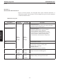
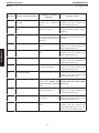
REVISION HISTORY
REASON FOR CHANGE
REV
DATE
0
Nov. 3, 1995
1
March 20, 1996
Update after proofreading
2
December, 1996
+!."! '")&)$ )! !&-&)#" .&*) " .&*)
3
June, 1997
+!."!
4
June, 2000
%" .*+ -3(*' (3 " ,"+' "! #*, ",.&) */).,&"- -/ % - %&)
!!&.&*) *# */,+*-&.&*) +"!' *+.&*)
+!." 4").",&)$ !"0& " '&$%. /' ,"+' "("). -" .&*) %+.", 5
February, 2001
,*$,( ++%&," $"
+*-&.&*) "!' *+.&*) ) "''"! $" (*!" !"- ,&+.&*) (*!&#&"! +$" )! ,"+,&)$ ) "2(&).&*) %+.", " .&*) .&"). +*-&.&*)&)$ 1,)&)$ !!"! *(&)$ #,*( ")*$,+%" ,,*, ("--$"- !!"!
6
February, 2002
Program: Innsbruck M3
– Introduction of a new console called “Console 2001”: modification of corresponding
illustrations.
Creation
LIST OF EFFECTIVE PAGES
PAGE
NUMBER
REVISION
NUMBER
Title page
Safety Instruction
6
6
i thru xiv
6
1–1 thru 1–22
6
2–1 thru 2–6
6
3–1 thru 3–30
6
4–1 thru 4–6
6
5–1 thru 5–2
6
PAGE
NUMBER
REVISION
NUMBER
PAGE
NUMBER
NUMBER
2135575–100TPH
xi
REVISION
NUMBER
FORMAT
A4
REVISION
6
GE Medical Systems
SENOGRAPHE 800T
REV 6
om 2135575–100
Blank page.
xii
GE Medical Systems
SENOGRAPHE 800T
REV 6
om 2135575–100
FOREWORD
This manual is provided for SENOGRAPHE 800T operators. It is designed to supply all the
information required for the correct use of this equipment.
xiii
GE Medical Systems
SENOGRAPHE 800T
REV 6
om 2135575–100
Blank page.
xiv
GE Medical Systems
SENOGRAPHE 800T
om 2135575–100
CHAPTER 1 – INTRODUCTION
SECTION 1
PRESENTATION
The SENOGRAPHE 800T is an x-ray system used primarily for mammography
examinations in the standing or sitting position. Breast localizations by two dimensional
localization is an additional function by using the optional cross hair device. If required, the
system can provide as well, high image quality radiography of specimens and of the hand and
foot.
The major features of the SENOGRAPHE 800T are: the Molybdenum x-ray tube – Rhodium
and Molybdenum filters – an entirely automatic exposure mode – a digital readout and display
of the arm angulation, of the compressed breast thickness and of the breast compression force
– a manual compression fine tuning – and its new ergonomic design.
Molybdenum x-ray tube
The SENOGRAPHE 800T is equipped with the well proven GE Molybdenum X–Ray tube
that provides high quality radiology images. The Rhodium filter allows better penetration of
glandular tissue and dose reduction for dense breasts.
Standard or magnification examinations can be performed. Focal spot sizes are: 0.3 for
contact exams and 0.1 for magnification exams.
Three modes of exposure are available:
AEC Mode
The Automatic Exposure Control (AEC) Mode controls density (mAs) and provides
exposures of constant optical density.
AOP Mode
The Automatic Optimization Parameters (AOP) Mode controls radiation. For a given
priority (dose reduction, contrast quality or compromise), the AOP Mode selects the filter,
and kV. It includes the AEC mode, and provides an automatic selection of the radiological
parameters (filter, kV, and mAs).
MAN Mode
In addition, a totally manual exposure mode (MAN) can be used in special cases. For example
when the breast does not cover the entire photocell, when examining breasts with silicone
implants, or when making examinations of extremities (hands, ...).
The new ergonomic design, coupled with features like digital readouts for gantry angle –
breast compressed thickness – breast compression force, and manual compression fine tune
ensures speed, accurate positioning and ease of use, with examination comfort for the patient.
1–1
INTRODUCTION
REV 6
GE Medical Systems
SENOGRAPHE 800T
INTRODUCTION
REV 6
om 2135575–100
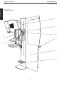
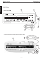
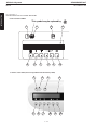
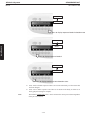
ILLUSTRATION 1–1
THE SENOGRAPHE 800T
1
7
3
5
4
8
6
2
1–2
GE Medical Systems
SENOGRAPHE 800T
om 2135575–100
SECTION 2
DESCRIPTION
2–1
Senographe 800T
See Illustration 1–1.
The SENOGRAPHE 800T is composed of the following components:
1. Column,
2. Readout for arm angulation, breast compressed thickness and compression force,
3. Emergency Stop push–button,
4. Control console,
5. Examination arm,
6. X–Ray protective shield,
7. Rotation shaft
8. Red light for cassette detection & exposure inhibit.
Note:
The Senographe 800T is equipped with an exposure interlock feature which prevents an
exposure from being made if there is no cassette in the Bucky/cassette holder, or if the
cassette from the previous exposure has not been changed. However, it is possible for
special purposes such as physicist testing for example to disable this interlock (see
chapter 3 for a detailed explanation).
Trying to make an exposure without a cassette in the Bucky/Cassette–holder or
without having changed the cassette between two exposures will make the red light
(8) come ON. The exposure will be inhibited.
It is not recommended to remove the exposed cassette from the Bucky/Cassette
holder by pushing it out with another cassette. This would prevent the exposure
interlock feature from functioning correctly.
When inserting a cassette in the Bucky, make sure that it is inserted all the way in and
firmly held between the two stoppers.
Examination Arm
This arm is connected to the Column by a rotating shaft. The Examination Arm can be rotated
from +180° to –160° about this shaft.
Rotation Shaft
This couples the examination arm to the Column. The angle of the arm can be read on the
digital display located at the bottom of the column.
Column
It consist mainly of a drive mechanism to hold and elevate the Examination arm. A readout,
located at the bottom of the column indicates:
Examination arm angulation (in degrees – °),
Compressed breast thickness (in millimeters – mm),
Compression force (in deca Newtons – daN).
Emergency Stop
Two Emergency Stop push–buttons are located one on either side of the rotating shaft.
Note:
The CE marking label is located on the bottom left hand side of the power supply cabinet
1–3
INTRODUCTION
REV 6
GE Medical Systems
SENOGRAPHE 800T
INTRODUCTION
REV 6
om 2135575–100
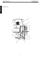
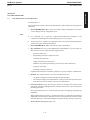
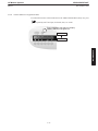
ILLUSTRATION 1–2
EXAMINATION ARM
1
3
12
13
2
14
11
5
4
7
15
6
9
11
12
13
10
8
1–4
GE Medical Systems
SENOGRAPHE 800T
2–2
om 2135575–100
Examination Arm
See Illustration 1–2. The Examination arm consists of:
1. X-ray Tube and Tube Housing Assembly.
2. The Collimator consists of the slot for the diaphragms. It also allows easy access to the
light bulb for easy replacement (see Chapter 3 – Section 1).
3. Guide Rail and Compression system including compression paddle and compression
paddle support.
4. Magnification Holes The Magnification plate is installed by latching the plate onto the
Receptor Arm in the holes provided for the selected magnification factor. To unlock the
magnification plate, press the lever located on the left of the mag. plate, and pull the plate
forward (as shown on label on top left side of the magnification plate).Two sets of holes
are provided for magnification. Magnification factors (1.5 & 1.8) are printed onto the
front part of the examination arm.
Note:
Always make sure that the magnification plate is correctly locked in place before starting
an exam.
Note:
The cassette holder is exclusively reserved for magnification. It must not be used for
standard exposures.
5. Compression is controlled by one pair of compression/decompression footpedals placed
on the floor (a second pair is available as an option).
Compression force, speed of compression and decompression height are
programmed by the SET-UP functions of the system (see details in chapter 3).
6. Manual adjustment is via thumbwheels located one on either side of the compression
paddle arm.
Note:
As a safety measure, the compression system is fitted with magnetic braking to avoid the
paddle from falling in the event of a power cut. If such a power cut occurred during an
examination, a force of around 5 daN could remain on the compression paddle. To
disengage the patient, the paddle should be gently raised to counteract this force.
Note:
Pressing the compression pedals and moving the thumbwheels illuminates the centering
light.
7. Compression paddle change: Slide the paddle arm sideways from the compression
paddle support.
Note:
For best results in AOP and in order to have the correct fit between the bucky and the
compression paddle, it is mandatory to match the format of the compression paddle with
the format of the Bucky when in contact mode, i.e. use the 18x24 compression paddle with
the 18x24 Bucky and use the 24x30 compression paddle with the 24x30 Bucky. The 24 x
30 paddle must not be used with the 18 x 24 Bucky.
8. The Film-Holder Assembly can receive both the 18x24 and 24x30 Buckys, and the
18x24 cassette holder. It is also equipped with the AEC photocell.
9. The Bucky and cassette-holder are installed on top of the Film-Holder Assembly.
Removal: Grip Bucky or cassette holder by its sides and pull forward to remove.
Insertion: Slide Bucky or cassette holder on film holder assembly. Check that the Bucky
pin located at the back of the Bucky is engaged in the pin guide located in the film holder
assembly. Push Bucky or cassette holder in fully.
1–5
INTRODUCTION
REV 6
GE Medical Systems
SENOGRAPHE 800T
REV 6
om 2135575–100
INTRODUCTION
10. Front adjustment of the photocell position is accomplished via a lever located on either
side of the film holder assembly. Five positions are available to suit patient anatomy.
11. Patient handles. The patient can steady herself during the examination by holding the
handrail located on either side of the examination arm.
12. The Up / Down and Rotation control buttons are located at the top and bottom of each
handrail.
13. The light centering switch is also located at the top and bottom of each handrail.
14. Rotation of +180° to –160° is available.
15. Red light for cassette detection and exposure inhibit.
Note:
The Senographe 800T is equipped with an exposure interlock feature which prevents an
exposure from being made if there is no cassette in the Bucky/cassette holder, or if the
cassette from the previous exposure has not been changed. However, it is possible for
special purposes such as physicist testing for example to disable this interlock (see
chapter 3 for a detailed explanation).
Trying to make an exposure without a cassette in the Bucky/Cassette–holder or
without having changed the cassette between two exposures will make the red light
(15) come ON. The exposure will be inhibited.
It is not recommended to remove the exposed cassette from the Bucky/Cassette
holder by pushing it out with another cassette. This would prevent the exposure
interlock feature from functioning correctly.
When inserting a cassette in the Bucky, make sure that it is inserted all the way in and
firmly held between the two stoppers.
1–6
GE Medical Systems
SENOGRAPHE 800T
2–3
om 2135575–100
Basic Accessories
The accessories delivered with the basic configuration of the SENOGRAPHE 800T consist
of:
18 x 24 capability including:
–
18 x 24 cm Bucky
–
18 x 24 cm cassette-holder for magnification
–
18 x 24 cm compression paddle
–
18x 24 collimator diaphragm for large focal spot
–
18x 24 collimator diaphragm for small focal spot
Square spot capability including:
–
Square spot compression paddle
–
Square spot collimator diaphragm for large focal spot
–
Square spot collimator diaphragm for small focal spot, 1st magnification factor
–
Square spot collimator diaphragm for small focal spot, 2nd magnification factor.
X–Ray Protective screen
Magnification plate
Face shield
Film marker (standard basic set of 8 markers – 4 for each breast)
Service manual
Operator Manual
1–7
INTRODUCTION
REV 6
GE Medical Systems
SENOGRAPHE 800T
INTRODUCTION
REV 6
2–4
om 2135575–100
Optional Accessories
The optional accessories for the SENOGRAPHE 800T consist of:
24 x 30 capability, including:
–
24 x 30 cm Bucky.
–
24 x 30 compression paddle.
–
24 x 30 cm collimator diaphragm for large focal spot.
–
24 x 30 cm collimator diaphragm for small focal spot.
Optical localizer (consisting of cross hair and biopsy paddle) for two dimensional biopsy.
Data Flash for recording and printing all exam and patient data directly onto the film.
Small round spot capability, including:
–
Small round spot compression paddle.
–
Small round spot collimator blade for large focal spot.
–
Small round spot collimator diaphragm for small focal spot, 1st magnification factor.
–
Small round spot collimator diaphragm for small focal spot, 2nd magnification
factor.
18x24 axillary compression paddle
Second set of compression / decompression footswitches
Storage unit for collimator diaphragm (total capacity of 5 diaphragms)
Cassette storage unit (capable of storing six 18x24 and six 24x30 cassettes, or six
unexposed 18x24 cassettes and six exposed 18x24 cassettes).
Mobile van installation kit
Examination chair
Accessories storage unit
1–8
GE Medical Systems
SENOGRAPHE 800T
2–5
om 2135575–100
Collimator Diaphragm – Bucky & Cassette Holder Selection Description
Choice of the Bucky, cassette holder and collimator diaphragms needed for the three key types
of exposures (18x24 – 24x30 – Magnification) has been made easy and effortless by color
coding these accessories:
WHITE – accessories for 18x24 contact exposures:
–
All collimator diaphragms needed for 18x24 contact exposures
–
18 x 24 Bucky
PURPLE – accessories for 24x30 contact exposures:
–
All collimator diaphragms needed for 24x30 contact exposures
–
24 x 30 Bucky
GREEN & PINK – accessories for all magnification exposures:
–
–
All collimator blades needed for magnification exposures:
–
GREEN for the 1.5 magnification factor
–
PINK for the 1.8 magnification factor
18 x 24 cassette holder for magnification
ÁÁÁÁÁ
ÁÁÁÁÁ
ÁÁÁÁÁÁ
ÁÁÁÁÁÁÁÁÁÁÁÁÁÁÁÁÁ
ÁÁÁÁÁ
ÁÁÁÁÁ
ÁÁÁÁÁÁ
ÁÁÁÁÁÁÁÁÁÁÁÁÁÁÁÁÁ
ÁÁÁÁÁ
ÁÁÁÁÁ
ÁÁÁÁÁÁ
ÁÁÁÁÁÁÁÁÁÁÁÁÁÁÁÁÁ
ÁÁÁÁÁ
ÁÁÁÁÁ
ÁÁÁÁÁÁ
ÁÁÁÁÁÁÁÁÁÁÁÁÁÁÁÁÁ
ÁÁÁÁÁ
ÁÁÁÁÁ
ÁÁÁÁÁÁ
ÁÁÁÁÁÁÁÁÁÁÁÁÁÁÁÁÁ
ÁÁÁÁÁ
ÁÁÁÁÁ
ÁÁÁÁÁÁ
ÁÁÁÁÁÁÁÁÁÁÁÁÁÁÁÁÁ
ÁÁÁÁÁ
ÁÁÁÁÁ
ÁÁÁÁÁÁ
ÁÁÁÁÁÁÁÁÁÁÁÁÁÁÁÁÁ
ÁÁÁÁÁ
ÁÁÁÁÁ
ÁÁÁÁÁÁ
ÁÁÁÁÁÁÁÁÁÁÁÁÁÁÁÁÁ
ÁÁÁÁÁ
ÁÁÁÁÁ
ÁÁÁÁÁÁ
ÁÁÁÁÁÁÁÁÁÁÁÁÁÁÁÁÁ
ÁÁÁÁÁ
ÁÁÁÁÁ
ÁÁÁÁÁÁ
ÁÁÁÁÁÁÁÁÁÁÁÁÁÁÁÁÁ
ÁÁÁÁÁ
ÁÁÁÁÁ
ÁÁÁÁÁÁ
ÁÁÁÁÁÁÁÁÁÁÁÁÁÁÁÁÁ
ÁÁÁÁÁ
ÁÁÁÁÁ
ÁÁÁÁÁÁ
ÁÁÁÁÁÁÁÁÁÁÁÁÁÁÁÁÁ
ÁÁÁÁÁ
ÁÁÁÁÁ
ÁÁÁÁÁÁ
ÁÁÁÁÁÁÁÁÁÁÁÁÁÁÁÁÁ
ÁÁÁÁÁ
ÁÁÁÁÁ
ÁÁÁÁÁÁ
ÁÁÁÁÁÁÁÁÁÁÁÁÁÁÁÁÁ
ÁÁÁÁÁ
ÁÁÁÁÁ
ÁÁÁÁÁÁ
ÁÁÁÁÁÁÁÁÁÁÁÁÁÁÁÁÁ
ÁÁÁÁÁ
ÁÁÁÁÁ
ÁÁÁÁÁÁ
ÁÁÁÁÁÁÁÁÁÁÁÁÁÁÁÁÁ
ÁÁÁÁÁ
ÁÁÁÁÁ
ÁÁÁÁÁÁ
ÁÁÁÁÁÁÁÁÁÁÁÁÁÁÁÁÁ
ÁÁÁÁÁ
ÁÁÁÁÁ
ÁÁÁÁÁÁ
ÁÁÁÁÁÁÁÁÁÁÁÁÁÁÁÁÁ
ÁÁÁÁÁ
ÁÁÁÁÁ
ÁÁÁÁÁÁ
ÁÁÁÁÁÁÁÁÁÁÁÁÁÁÁÁÁ
ÁÁÁÁÁ
ÁÁÁÁÁ
ÁÁÁÁÁÁ
ÁÁÁÁÁÁÁÁÁÁÁÁÁÁÁÁÁ
ÁÁÁÁÁ
ÁÁÁÁÁ
ÁÁÁÁÁÁ
ÁÁÁÁÁÁÁÁÁÁÁÁÁÁÁÁÁ
ÁÁÁÁÁ
ÁÁÁÁÁ
ÁÁÁÁÁÁ
ÁÁÁÁÁÁÁÁÁÁÁÁÁÁÁÁÁ
ÁÁÁÁÁ
ÁÁÁÁÁ
ÁÁÁÁÁÁ
ÁÁÁÁÁÁÁÁÁÁÁÁÁÁÁÁÁ
ÁÁÁÁÁ
ÁÁÁÁÁ
ÁÁÁÁÁÁ
ÁÁÁÁÁÁÁÁÁÁÁÁÁÁÁÁÁ
ÁÁÁÁÁ
ÁÁÁÁÁ
ÁÁÁÁÁÁ
ÁÁÁÁÁÁÁÁÁÁÁÁÁÁÁÁÁ
The collimator diaphragms supplied with the unit are labeled as follows:
Size printed
on
diaphragm
Color
Focal spot
used
18 x 24
White
Large (0.3)
Large focus. Full field
Included in the basic configuration
10 x 10
White
Large (0.3)
Large focus. Square collimation
Included in the basic configuration
18 x 24
White
Small (0.1)
Small focus. Full field
Included in the basic configuration
14 x 14
Green
Small (0.1)
Small focus. Square collimation. 1.5 magnification
Included in the basic configuration
16 x 16
Pink
Small (0.1)
Small focus. Square collimation. 1.8 magnification
Included in the basic configuration
Ø6
White
Large (0.3)
Large focus. Spot collimation
Optional. Delivered with “ small round spot capability ”
Ø9
Green
Small (0.1)
Small focus. Spot collimation. 1.5 magnification
Optional. Delivered with “ small round spot capability ”
Ø 10
Pink
Small (0.1)
Small focus. Spot collimation. 1.8 magnification
Optional. Delivered with “ small round spot capability ”
24 x 30
Purple
Large (0.3)
Large focus. Full field
Optional. Delivered with “ 24x30 capability ”
24 x 30
Purple
Small (0.1)
Small focus. Full field
Optional. Delivered with “ 24x30 capability ”
Usage / Comments
1–9
INTRODUCTION
REV 6
GE Medical Systems
SENOGRAPHE 800T
INTRODUCTION
REV 6
om 2135575–100
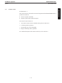
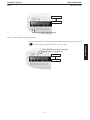
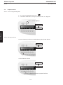
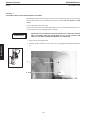
ILLUSTRATION 1–3
CONTROL CONSOLE
Control Console CDRH
Control Console 2001 (in forward production from february 2002)
1–10
GE Medical Systems
SENOGRAPHE 800T
2–6
om 2135575–100
Control Console
See Illustration 1–3.
The Control Console is the interface between the Operator and the SENOGRAPHE 800T. It
provides two functions:
Receives operator commands.
Displays replies and/or machine messages.
The Control Console consists of:
1. The Control Console, which is installed on the protective lead screen.
2. Connecting cable to generator.
3. Special plug reserved for Senographe
4. Plug for connecting cable to generator
For a detailed description of the control console use, refer to Section 3.
1–11
INTRODUCTION
REV 6
GE Medical Systems
SENOGRAPHE 800T
INTRODUCTION
REV 6
om 2135575–100
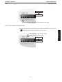
ILLUSTRATION 1–4
CONTROL KEYBOARD
Control Console CDRH
Control Console 2001 (in forward production from february 2002)
1–12
GE Medical Systems
SENOGRAPHE 800T
om 2135575–100
The control console is the same console on all GE Medical Systems units (DMR, 700T and
800T). But since the features are different between the Senographe DMR and 800T, some
keys will not be operational on the Senographe 800T control keyboard (the focal spot and
track selection keys).
The Control console consists of the following keys (see illustration 1–4):
1. SENOGRAPHE 800T ‘ON’
Note:
It is important not to touch the compression/decompression footpedals or the
compression manual adjustment knobs during the power–up sequence.
After the power–up sequence, the footpedals must be used (not the manual adjustment
knobs) to bring the compression paddle up.
2. SENOGRAPHE 800T ‘OFF’
3. SET UP Menu
4. Readout for messages and keys selections
5. Focal spot selection (not operational on Senographe 800T because focal spot size is
automatically selected by insertion of the appropriate collimator diaphragm into the
collimator slot).
6. Track: Molybdenum (Mo) only. No other selection available.
7. Filter selection
8. Film Density Control (FDC) decrements (–)
9. Film Density Control (FDC) increments (+)
10. Screen/film Combination (SFC) selection
11. kV and mAs readout
12. kV selection
13. mAs selection
14. AOP, AEC, and Manual Mode selection
15. Exposure Enable indicator lamp
16. Exposure indicator lamp
17. Exposure Disable indicator lamp
18. Centering Light ON-button
19. Exposure Interrupt indicator button and reset
20. Rad prep
21. Exposure button
22. Compression release Button
Note:
The symbol
located on the control panel means that you must read the appropriate
chapter in the operator manual before taking any action.
1–13
INTRODUCTION
REV 6
GE Medical Systems
SENOGRAPHE 800T
INTRODUCTION
REV 6
om 2135575–100
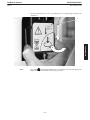
ILLUSTRATION 1–5
LEFT–HAND SECTION OF CONTROL KEYBOARD
Control Console CDRH
Control Console 2001 (in forward production from february 2002)
1–14
GE Medical Systems
SENOGRAPHE 800T
REV 6
om 2135575–100
3–1
INTRODUCTION
SECTION 3
CONTROL KEYBOARD
Left–hand Section of Control Keyboard
See Illustration 1–5.
The left–hand section of the Control Console Keyboard is used to initialize or select generator
parameters.
1. SENOGRAPHE 800 T ‘ON’: The green indicator lamp is illuminated. The Control
Console displays the last configuration used.
Note:
It is important not to touch the compression/decompression footpedals or the
compression manual adjustment knobs during the power–up sequence.
After the power–up sequence, the footpedals must be used (not the manual adjustment
knobs) to bring the compression paddle up.
2. SENOGRAPHE 800 T ‘OFF’: The indicator lamp is illuminated.
3. SET UP Menu: Press key to enter Maintenance and Installation, or to access SET UP
Menu which is used to modify the following parameters:
–
Speed of compression
–
Programming maximum compression force
–
Automatic decompression.
–
Height of automatic decompression.
–
Minimum Acceptable Optical density for each screen/film combination.
–
Language of messages
–
Disabling of exposure interlock
Explanation and description of all these parameters is given in Chapter 3, Maintenance.
4. Readout: The readout consists of two lines of 40-characters each.
–
The upper line displays warning messages and fault messages.
–
The lower line displays selected parameters: focal spot, focal track (Mo), filter, FDC
(Film Density Control), and SFC (Screen Film Combination).
5. Focal Spot selection: Since the focal spot selection is ensured by the insertion of the
appropriate collimator diaphragm into the collimator slot, this key is not operational on
the Senographe 800T.
The readout indicates the size of the selected focal spot in the language programmed at
installation.
When magnification is selected, i.e. when the appropriate 0.1 small focal spot collimator
diaphragm is inserted into the collimator slot, the system automatically selects the small
focal spot. When a 0.3 collimator diaphragm is inserted, the large focal spot is selected..
6. Track selection: Molybdenum (Mo) only.
1–15
GE Medical Systems
SENOGRAPHE 800T
REV 6
om 2135575–100
INTRODUCTION
7. Filter selection: Press key to change filtration (two selections are available:
Molybdenum – Mo or Rhodium – Rh).
In AEC and manual mode, the key selects one of the two filters.
The readout indicates the type of filter: Mo (molybdenum) or Rh (rhodium).
In AOP mode, selection is automatic (pressing the key has no effect).
8. Film Density Control (FDC) decrements FDC (-): In AOP and AEC modes, press key
to reduce density correction by one step.
9. Film Density Control (FDC) increments FDC (+): In AOP and AEC modes, press key
to increase density correction by one step.
Note:
FDC (+), FDC (–): pressing these keys in manual mode has no effect.
Correction is available in 11 steps (-5 through +5). Density variation is 0.2 OD (optical
density) by default for each step and may be programmed at installation by the GEMS
service engineer.
10. Screen-film Combination (SFC) selection:
Note:
–
In AOP and AEC modes, press key to select screen-film combination speed.
–
The cycle turns on the number of SFCs calibrated at installation.
–
A maximum of five SFCs can be calibrated.
–
The name of the SFC (specified at installation) appears on the readout.
Pressing this key in manual mode has no effect.
1–16
GE Medical Systems
SENOGRAPHE 800T
REV 6
om 2135575–100
INTRODUCTION
Blank page.
1–17
GE Medical Systems
SENOGRAPHE 800T
INTRODUCTION
REV 6
om 2135575–100
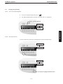
ILLUSTRATION 1–6
CENTRAL SECTION OF CONTROL KEYBOARD
Control Console CDRH
Control Console 2001 (in forward production from february 2002)
1–18
GE Medical Systems
SENOGRAPHE 800T
3–2
om 2135575–100
Central Section of Control Console Keyboard
See Illustration 1–6.
The central section of the Control Console Keyboard is used to select and display the kV and
mAs values.
1. kV and mAs Readout
–
In AOP mode the readout displays the kV values selected by the system and the mAs
values output.
At start of compression, the kV readout displays the code of the mode selected:
CNT, STD, and DOSE. The mAs readout displays the AUTO mode.
At end of exposure, the kV readout displays the kV values selected. The kV readout
displays the first letter of the code of the selected mode (C, S, or D) and the mAs
readout displays the mAs values output.
–
In AEC mode, the readout displays the kV values selected by the operator and the
mAs values output preceded by the letter A.
–
In manual mode the readout displays the kV and mAs values selected by the
operator.
2. kV selection: The kV values are displayed 22 through 35 in steps of 1 kV via the knurled
knob (14 positions). At end-of-travel (there is no mechanical stop), the readout displays
the maximum or minimum kV values (22 kV or 35 kV). In AOP mode, rotating the knob
has no effect.
3. mAs selection: The mAs values are displayed 4 through 600 mAs via the knurled knob.
At end-of-travel (there is no mechanical stop), the readout displays the minimum or
maximum mAs values (4 or 600 mAs). In AOP and AEC mode, turning the knob has no
effect.
4. AOP, AEC, and Manual Mode selection
The key selects the AOP, AEC and Manual modes successively.
The AOP mode is broken down into three positions, allowing three priorities:
–
CNT: contrast priority,
–
STD: standard dose/contrast compromise,
–
DOSE: dose reduction priority.
Pressing the key selects the Contrast, Standard, and Dose priorities. At the start of
compression, the three priorities are displayed on the kV readout. When the exposure is
complete, the initial letter of the code selected is displayed on the kV readout.
The filter is selected automatically (pressing the key for each has no effect). The
following can be selected via their keys: screen-film combination, film density control.
CAUTION
BREAST COMPRESSION IS ESSENTIAL IN AOP.
The AEC mode is used to select the kV values manually, and mAs values automatically.
The following selections are available via their keys: filter, focal spot, and film density
control.
The Manual mode is used to select kV and mAs values.
The Film Density Control key and the Screen-Film Combination key have no effect in
manual mode.
1–19
INTRODUCTION
REV 6
GE Medical Systems
SENOGRAPHE 800T
INTRODUCTION
REV 6
om 2135575–100
ILLUSTRATION 1–7
RIGHT–HAND SECTION OF CONTROL KEYBOARD
Control Console CDRH
Control Console 2001 (in forward production from february 2002)
1–20
GE Medical Systems
SENOGRAPHE 800T
3–3
om 2135575–100
Right–hand Section of Control Keyboard
See Illustration 1–7.
This section is used to prepare and initiate an exposure, control the centering light, and for
decompression and system reset.
1. Exposure Enable lamp (green)
When illuminated, exposure is enabled.
2. Exposure indicator lamp (yellow)
Lamp is illuminated from start to end of exposure.
A buzzer sounds at the end of exposure.
3. Exposure Disable lamp
When red lamp is illuminated, exposure is disabled. Follow instructions displayed on
readout on left section of Control Console.
A list of messages is given in Chapter 3 – Section 3.
4. Centering Light ON-button. Press key to illuminate centering light for 30 seconds. The
key is illuminated.
5. Exposure Interrupt lamp (yellow indicator lamp). When the exposure is Interrupted,
the lamp is illuminated and a buzzer sounds. Hit key to stop buzzer and reset system.
6. Rad Prep (activates green indicator lamp). Press key to prepare the exposure (anode
rotation).When lamp is illuminated, exposure can be triggered.
Note:
If Rad Prep is released before the lamp is illuminated, the preparation is canceled. When
the green lamp is illuminated, preparation stops one second after release.
7. Exposure button: Press and hold to make exposure. To stop exposure immediately,
release key. A buzzer sounds at the end of exposure.
In AOP mode and following preparation (anode rotation), the total exposure is split into
three phases:
1. A test exposure of 15 ms is made. It allows selection of the optimum kV, and filter
combination in the selected priority.
2. A pause during which the kV, and filter are put in place.
3. An exposure during which the X–Ray exposure is made. The operator should
maintain pressure on the button until the buzzer stops
8. Compression release button: Press to release compression. The compression paddle
automatically moves up to the pre–programmed autodecompression height.
If autodecompression is “ ON ” it is not necessary to press the compression release
button.
1–21
INTRODUCTION
REV 6
GE Medical Systems
SENOGRAPHE 800T
INTRODUCTION
REV 6
om 2135575–100
Blank page.
1–22
GE Medical Systems
SENOGRAPHE 800T
REV 6
om 2135575–100
CHAPTER 2 – PREPARING AN EXAMINATION
SECTION 1
PREPARING THE EQUIPMENT
For standard exposures, use 18x24 cm or 24x30 cm cassettes and a compression paddle
suitable for the selected format. Use of the Bucky is mandatory for contact views. The cassette
holder must only be used in Magnification.
Note:
For best results in AOP and in order to have the correct fit between the bucky and the
compression paddle, it is mandatory to match the format of the compression paddle with
the format of the bucky when in contact mode, i.e. use the 18 x 24 compression paddle with
the 18 x 24 Bucky and use the 24 x 30 paddle with the 24 x 30 Bucky. The 24 x 30 paddle
must not be used with the 18 x 24 Bucky.
Note:
The Senographe 800T is equipped with an exposure interlock feature which prevents an
exposure from being made if there is no cassette in the Bucky/cassette holder, or if the
cassette from the previous exposure has not been changed. However, it is possible for
special purposes such as physicist testing for example to disable this interlock (see
chapter 3 for a detailed explanation).
Trying to make an exposure without a cassette in the Bucky/Cassette–holder or
without having changed the cassette between two exposures will result in a beep
sound and the red light (8) will come on. The exposure will be inhibited.
It is not recommended to remove the exposed cassette from the Bucky/Cassette
holder by pushing it out with another cassette. This would prevent the exposure
interlock feature from functioning correctly.
When inserting a cassette in the Bucky, make sure that it is inserted all the way in and
firmly held between the two stoppers.
Different field sizes and compression paddles can be used.
Note:
Use of the Bucky is not recommended in magnification.
RAD PARAMETERS
The Rad parameter selection depends on the filter configuration.
ÁÁÁÁÁÁÁ
ÁÁÁÁÁÁÁ
ÁÁÁÁÁÁÁÁÁÁÁÁÁ
ÁÁÁÁÁÁÁ
ÁÁÁÁÁÁÁ
ÁÁÁÁÁÁÁÁÁÁÁÁÁ
ÁÁÁÁÁÁÁ
ÁÁÁÁÁÁÁ
ÁÁÁÁÁÁÁÁÁÁÁÁÁ
ÁÁÁÁÁÁÁ
ÁÁÁÁÁÁÁ
ÁÁÁÁÁÁÁÁÁÁÁÁÁ
ÁÁÁÁÁÁÁ
ÁÁÁÁÁÁÁ
ÁÁÁÁÁÁÁÁÁÁÁÁÁ
FILTER CONFIGURATIONS
TRACK
FILTER
KV RANGE
Mo
Mo
22 through 35
Mo
Rh
22 through 35
As image contrast quality depends on kV values used, note that an increase in the kV value
may reduce radiation dose to the patient, but it will reduce the contrast of the image.
A reduction in the kV value improves film contrast but increases the radiation dose to the
patient.
2–1
PREPARING
AN EXAMINATION
Set the image receptor, field size, collimator diaphragm and compression paddle for the
required view.
GE Medical Systems
SENOGRAPHE 800T
REV 6
om 2135575–100
The choice of priority to dose reduction or to optimum contrast is left to the discretion of the
operator.
Use of the AOP Mode provides the best quality/dose compromise for each priority selected by
the operator.
THIS MACHINE USES A SOPHISTICATED ALGORITHM TO
AUTOMATICALLY DETERMINE OPTIMAL PARAMETERS TO
PRODUCE MAMMOGRAMS (AOP). FOR THIS, MANY KVP/FILTRATION
COMBINATIONS ARE AVAILABLE TO BE CHOSEN FROM. IN REGULAR
AUTOMATIC EXPOSURE CONTROL (AEC) MODE, THE SAME
CONDITIONS ARE AVAILABLE, AND MAY BE CHOSEN BY THE USER.
HOWEVER, FOR BEST RESULTS, ONLY CERTAIN CONFIGURATIONS
SHOULD BE USED.
PREPARING
AN EXAMINATION
WARNING
Compression
It is advised that sufficient breast compression be used to benefit the following image
quality/dose reduction advantages:
Compression reduces motion blurring.
Compression reduces geometric unsharpness by ensuring direct contact between breast
and image receptor, and by spreading apart glandular breast tissue.
Compression improves film contrast and reduces scattered radiation in proportion to the
reduction in the thickness of the tissue irradiated.
Compression spreads the breast laterally, and reduces the breast to a constant thickness.
This shortens exposure time, and consequently reduces the average glandular dose.
Good compression is obtained when the breast surface is taut to the touch.
Decompression can be programmed to occur automatically after exposure is complete
When exposure is complete, automatic decompression is available by pressing the button on
the right hand side of the control console.
Note:
As a safety measure, the compression system is fitted with magnetic braking to avoid the
paddle falling in the event of a power cut. If such a power cut occurred during an
examination, a force of around 5 daN could remain on the compression paddle. To
disengage the patient, the paddle should be gently raised to counteract this compression
force.
SECTION 2
EXPOSURE MODE
2–1
AOP Mode
The AOP (Automatic Optimization Parameters) Mode controls radiation and allows the
system to select the main parameters.
It optimizes the filter/kV configuration as a function of the required image quality, and of the
composition of the breast being examined.
The AOP Mode includes the AEC Mode, and ensures constant density.
2–2
GE Medical Systems
SENOGRAPHE 800T
REV 6
om 2135575–100
The AOP Mode has three options:
Contrast (CNT):
Contrast priority
Standard (STD):
Compromise between contrast and dose.
Dose (DOSE):
Dose reduction priority
The operator selects:
Priority (CNT, STD, DOSE).
Focal spot,
Screen-film combination.
Density correction, when necessary.
Density correction is used only when an optical density change in the image is required.
Breast compression is essential when using the AOP Mode.
CAUTION
The system displays inhibited messages and automatically selects the following parameters:
Filter (Mo, Rh),
kV values,
mAs values.
The AOP Mode can be used for standard exposures, magnified exposures, or for the
examination of the chest wall.
For standard exposures, the Bucky must be used.
In magnification, use of the Bucky is not recommended. The operator should use the cassette
holder.
Always make sure that the magnification plate is correctly locked in place before starting an
exam.
The system automatically selects the small focal spot (0.1) when magnification is
selected, i.e. when the appropriate small focal spot collimator diaphragm is inserted into
the collimator slot.
The system automatically selects the large focal spot (0.3) when a 0.3 collimator diaphragm is
inserted.
To maintain optimal image quality, the user must check on the control panel display that
the selected focal spot is dedicated to the selected examination mode: Contact
examination (normal) = 0.3. Magnification = 0.1
2–2
AEC Mode
The Automatic Exposure Control (AEC) Mode controls density (mAs) and provides
exposures of constant optical density.
2–3
PREPARING
AN EXAMINATION
For each of the above options and as a function of the breast composition, the AOP Mode
selects the filter/kV configuration.
GE Medical Systems
SENOGRAPHE 800T
REV 6
om 2135575–100
The operator selects the following parameters:
Filter (Mo, Rh),
Focal spot (0.3 or 0.1 by inserting the correct collimator diaphragm),
Screen/film combination,
kV values.
PREPARING
AN EXAMINATION
The operator can modify the density correction.
Place the breast to be examined on the Bucky, making sure the breast is properly positioned
over the photocell.
Inhibiting commands will be displayed on the system.
2–2–1 Contact Exposures
The Bucky must be used for contact exposures, not the cassette holder which is reserved for
magnification.
Select configurations and kV values given in manual mode.
The screen-film combination selection depends on user preference.
2–2–2 Magnification
Note:
Use of the Bucky is not recommended in magnification. The operator should use the
cassette holder.
Always make sure that the magnification plate is correctly locked in place before starting
an exam.
When magnification is selected, i.e. when the appropriate small focal spot collimator
diaphragm is inserted into the collimator slot., the system automatically selects the small focal
spot (0.1).
When 0.3 diaphragms are inserted, the system automatically selects the large focal spot (0.3).
To maintain optimal image quality, the user must check on the control panel display that the
selected focal spot is dedicated to the selected examination mode: Contact examination
(normal) = 0.3.
Magnification = 0.1
Select configurations and kV values.
2–2–3 Examination of Chest Wall
Select configurations and kV values according to the composition of the region examined.
Note:
2–3
The Bucky must be used.
Manual Mode
The Manual Mode can be used for standard exposures, magnified exposures, or for the
examination of the chest wall.
It is recommended to use Manual Mode when the object to be x-rayed cannot be correctly
positioned over the AEC photocell.
2–4
GE Medical Systems
SENOGRAPHE 800T
REV 6
om 2135575–100
The operator selects the following parameters:
Filter (Mo, Rh),
Focal spot (0.3 or 0.1 by inserting the correct collimator diaphragm),
Screen–film combination,
kV values,
mAs values.
Selecting the screen/film combination in Manual Mode has no effect. The user is
recommended to consider the speed of the screen-film combination when selecting the kV
and mAs values.
2–3–1 Contact Exposures
The Bucky must be used for contact exposures, not the cassette holder which is reserved for
magnification.
According to the composition of the breast to be examined, select a configuration with
suitable kV values.
Note that change to use of the Rhodium (Rh) filter for very dense breasts may provide better
tissue visualization and a lower average glandular dose.
Tables 2–2 (below) gives examples of the most frequently used configurations and kV values.
ÁÁÁÁÁÁÁ
ÁÁÁÁÁÁÁ
ÁÁÁÁÁÁÁÁÁÁÁÁÁ
ÁÁÁÁÁÁÁ
ÁÁÁÁÁÁÁ
ÁÁÁÁÁÁÁÁÁÁÁÁÁ
ÁÁÁÁÁÁÁ
ÁÁÁÁÁÁÁ
ÁÁÁÁÁÁÁÁÁÁÁÁÁ
ÁÁÁÁÁÁÁ
ÁÁÁÁÁÁÁ
ÁÁÁÁÁÁÁÁÁÁÁÁÁ
ÁÁÁÁÁÁÁ
ÁÁÁÁÁÁÁ
ÁÁÁÁÁÁÁÁÁÁÁÁÁ
COMMON EXPOSURES
Note:
TRACK
FILTER
KV RANGE
Mo
Mo
25 through 35
Mo
Rh
25 through 35
The screen/film combination selection depends on user preference.
The mAs value selection depends on the screen speed.
2–3–2 Magnification
Note:
Use of the Bucky is not recommended in magnification, the operator should use the
cassette holder.
Always make sure that the magnification plate is correctly locked in place before starting
an exam.
When magnification is selected, i.e. when the appropriate small focal spot collimator
diaphragm is inserted into the collimator slot., the system automatically selects the small
focal spot (0.1).
When 0.3 diaphragms are inserted, the system automatically selects the large focal spot
(0.3).
To maintain optimal image quality, the user must check on the control panel display that the
selected focus is dedicated to the selected examination mode: Contact examination (normal)
= 0.3.
Magnification = 0.1
2–5
PREPARING
AN EXAMINATION
The system displays the inhibit conditions.
GE Medical Systems
SENOGRAPHE 800T
REV 6
om 2135575–100
Select configurations and kV values.
When the Bucky is removed and the cassette holder is being used, the mAs values are
approximately divided by 2.
2–3–3 Examination of Chest Wall
Select configurations and kV values to suit thickness and density of region examined.
PREPARING
AN EXAMINATION
Note:
Use of the Bucky is mandatory.
SECTION 3
PATIENT POSITIONING
Before beginning the mammogram, observe the following points:
Before positioning the patient, make a visual assessment of the breast area, and note
anything which may affect or be adversely affected by the correct positioning of the breast
for the mammogram, for example, warts, scarring, or skin which is not intact. In patients
with large breasts, perspiration under the breast can cause the skin to soften, and become
paper-thin.
To position the breast properly for a mammogram in the CC position, it is essential that
the breast is lifted away from the chest wall and gently pulled forward, in order to
visualize the maximum amount of breast tissue. Such pulling and lifting is necessary for
correct positioning, but can cause damaged skin to tear slightly, and may cause bleeding.
If any condition exists which may cause unusual discomfort or tearing of the skin, the
patient should be told of the importance of correct positioning, and should be warned in
advance of the possibility that minor tearing and /or slight bleeding might occur.
Use suitable techniques for the positioning of patients with breast implants.
GEMS can take no responsibility for injury to the patient caused by the use of heating or
warming devices external to the system.
2–6
GE Medical Systems
SENOGRAPHE 800T
REV 6
om 2135575–100
CHAPTER 3 – MAINTENANCE
SECTION 1
CLEANING & DISINFECTION
GENERAL INFORMATION
Adequate cleaning and disinfection is necessary to prevent disease transmission.
Be sure to thoroughly clean and disinfect equipment surfaces that contact the
patient and all equipment surfaces likely to become soiled during use.
CAUTION
A CRITICAL device is one which routinely penetrates the skin or mucous membranes
during use and therefore poses a high risk of infection if it is not sterile. Such devices
(e.g., surgical instruments, needles, catheters or infusion sets) must be made sterile prior
to use.
A SEMICRITICAL device is one which contacts mucous membranes but does not
penetrate normally sterile areas of the body. Such devices (e.g., endoscopes, speculum)
should be made sterile whenever practical, but high level disinfection is usually
acceptable prior to use.
A NONCRITICAL device is one which contacts intact skin during routine use. Such
devices (e.g., patient exam tables, blood pressure cuff, etc.) present a much lower risk of
infection and, therefore, a low level disinfection is usually acceptable. However, in cases
when there is concern for cross contamination, an intermediate level disinfection
should be done between patients.
The patient contact surfaces of mammography equipment are noncritical, and either low level
or intermediate level disinfection is adequate for routine use. These surfaces are the
Bucky/cassette holder, compression paddles and magnification plate. Other surfaces that
may have casual contact with the patient and should be considered for intermediate level
disinfection are the face shield and tummy shield.
CAUTION
Improper cleaning methods or the use of certain cleaning and disinfecting agents
can damage the equipment, cause poor imaging performance or increase the risk
of electric shock. To avoid possible injury or equipment damage:
Do not use harsh detergents, abrasive cleaners, high alcohol concentration or
Methanol at any concentration. If skin preparations contain high alcohol
concentrations, allow sufficient drying time before applying compression;
Do not expose equipment parts to steam or high temperature sterilization;
Never allow liquids to enter the internal parts of the equipment. If you become
aware of liquid entry, disconnect the electrical supply and have the equipment
checked by qualified service personnel before returning it to use.
3–1
MAINTENANCE
The level of disinfection required for a patient contact device depends on the type of contact
that occurs:
GE Medical Systems
SENOGRAPHE 800T
REV 6
om 2135575–100
EQUIPMENT CLEANING INSTRUCTIONS
Patient contact surfaces should be washed with mild soap in lukewarm water. Removable
parts that do not contain electrical components such as the compression paddles may be
removed from the equipment and immersed if needed. Equipment parts such as the
Bucky/cassette holder that enclose electrical components must not be immersed but rather
cleaned with a soft dampened cloth, taking care not to allow liquids to enter the equipment.
Surfaces should be scrubbed as needed using a soft sponge, gauze or cloth to remove all visible
residue. Scrubbing with a soft bristle brush (such as a toothbrush) may be necessary to reach
corners or to remove material that has dried onto the surface. Subsequent disinfection may not
be effective if the surfaces are not thoroughly clean.
Rinse all surfaces with clean water to remove visible soap residue, taking care to avoid liquid
entry to internal equipment parts. Dry surfaces with a soft cloth to remove any visible residue.
MAINTENANCE
LOW LEVEL OR INTERMEDIATE LEVEL DISINFECTION
Patient contact surfaces may be disinfected with a suitable liquid chemical germicide.
Surfaces must first be cleaned of all visible contamination (see above). The liquid germicide
must have a minimum contact time with the surface to be effective. Equipment parts should be
sprayed with a fine mist applicator or wiped with a wet cloth or sponge as directed by the
instructions for use provided with the germicide. If needed, removable parts not containing
electrical components (compression paddles and magnification plate) can be removed and
immersed. Further rinsing or wiping with clear water and drying with a soft cloth should be
done to remove any germicide residue that may remain. Take care to avoid liquid entry to
internal equipment parts.
HIGH LEVEL DISINFECTION
In the event you feel a high level disinfection is necessary due to equipment contact with
breached skin or being used with infected or immune compromised patients, the same patient
contact surfaces may be high level disinfected with a liquid chemical germicide rated for high
level disinfection. The same process used as that for intermediate level disinfection is
generally followed; however, the time of contact is usually much longer for high level
disinfection.
RECOMMENDED GERMICIDES
The following legally marketed products have been used on GE equipment without causing
equipment damage.
Low or Intermediate Disinfection
LpHse, manufactured by Calgon Vestal Laboratories, St. Louis, MO, U.S.A., EPA Reg. No.
1043–92 (510(k) K931342)
VESPHENE IIse, manufactured by Calgon Vestal Laboratories, St. Louis, MO, U.S.A., EPA
Reg. No. 1043–87 (510(k) K931573)
3–2
GE Medical Systems
SENOGRAPHE 800T
REV 6
om 2135575–100
High Level Disinfection
CIDEX, manufactured by Johnson & Johnson Medical, Inc., Arlington, TX, U.S.A., EPA
Reg. No. 7078–1, EPA Est. No. 36126–PR–1 (510(k) K924434).
MAINTENANCE
CAUTION
Always follow the germicide manufacturer’s instructions and precautions for
mixing, storage, method of application, contact time, rinsing requirements,
protective clothing, shelf life and disposal to help assure effective and safe use of
the product.
3–3
GE Medical Systems
SENOGRAPHE 800T
REV 6
om 2135575–100
SECTION 2
PREVENTIVE MAINTENANCE
Despite its inherent qualities, the Senographe 800T requires minimum maintenance. A
maintenance program, whose frequency varies according to the type of use of the equipment,
is outlined in the table below.
Maintenance Program
ÁÁÁÁÁÁÁÁ
ÁÁÁÁÁÁÁÁÁÁÁ
ÁÁÁÁÁÁÁÁÁÁÁÁÁÁÁÁÁ
ÁÁÁÁÁÁÁÁ
ÁÁÁÁÁÁÁÁÁÁÁ
ÁÁÁÁÁÁÁÁÁÁÁÁÁÁÁÁÁ
ÁÁÁÁÁÁ
ÁÁÁÁÁÁ
ÁÁÁÁÁÁÁÁ
ÁÁÁÁÁÁÁÁÁÁÁ
ÁÁÁÁÁÁÁÁÁÁÁÁÁÁÁÁÁ
ÁÁÁÁÁÁÁÁ
ÁÁÁÁÁÁ
ÁÁÁÁÁÁ
ÁÁÁÁÁÁÁÁÁÁÁÁÁÁÁÁÁ
ÁÁÁÁÁÁÁÁ
ÁÁÁÁÁÁ
ÁÁÁÁÁÁ
ÁÁÁÁÁÁÁÁÁÁÁÁÁÁÁÁÁ
ÁÁÁÁÁÁÁÁ
ÁÁÁÁÁÁ
ÁÁÁÁÁÁ
ÁÁÁÁÁÁÁÁÁÁÁÁÁÁÁÁÁ
ÁÁÁÁÁÁÁÁ
ÁÁÁÁÁÁ
ÁÁÁÁÁÁ
ÁÁÁÁÁÁÁÁÁÁÁÁÁÁÁÁÁ
ÁÁÁÁÁÁÁÁ
ÁÁÁÁÁÁ
ÁÁÁÁÁÁ
ÁÁÁÁÁÁÁÁÁÁÁÁÁÁÁÁÁ
ÁÁÁÁÁÁÁÁ
ÁÁÁÁÁÁ
ÁÁÁÁÁÁ
ÁÁÁÁÁÁÁÁÁÁÁÁÁÁÁÁÁ
ÁÁÁÁÁÁÁÁ
ÁÁÁÁÁÁ
ÁÁÁÁÁÁ
ÁÁÁÁÁÁÁÁÁÁÁÁÁÁÁÁÁ
ÁÁÁÁÁÁÁÁ
ÁÁÁÁÁÁ
ÁÁÁÁÁÁ
ÁÁÁÁÁÁÁÁÁÁÁÁÁÁÁÁÁ
ÁÁÁÁÁÁÁÁ
ÁÁÁÁÁÁ
ÁÁÁÁÁÁ
ÁÁÁÁÁÁÁÁÁÁÁÁÁÁÁÁÁ
ÁÁÁÁÁÁÁÁ
ÁÁÁÁÁÁ
ÁÁÁÁÁÁ
ÁÁÁÁÁÁÁÁÁÁÁÁÁÁÁÁÁ
ÁÁÁÁÁÁÁÁ
ÁÁÁÁÁÁ
ÁÁÁÁÁÁ
ÁÁÁÁÁÁÁÁÁÁÁÁÁÁÁÁÁ
ÁÁÁÁÁÁÁÁ
ÁÁÁÁÁÁ
ÁÁÁÁÁÁ
ÁÁÁÁÁÁÁÁÁÁÁÁÁÁÁÁÁ
ÁÁÁÁÁÁÁÁ
ÁÁÁÁÁÁ
ÁÁÁÁÁÁ
ÁÁÁÁÁÁÁÁÁÁÁÁÁÁÁÁÁ
ÁÁÁÁÁÁÁÁ
ÁÁÁÁÁÁ
ÁÁÁÁÁÁ
ÁÁÁÁÁÁÁÁÁÁÁÁÁÁÁÁÁ
ÁÁÁÁÁÁÁÁ
ÁÁÁÁÁÁ
ÁÁÁÁÁÁ
ÁÁÁÁÁÁÁÁÁÁÁÁÁÁÁÁÁ
ÁÁÁÁÁÁÁÁ
ÁÁÁÁÁÁ
ÁÁÁÁÁÁ
ÁÁÁÁÁÁÁÁÁÁÁÁÁÁÁÁÁ
ÁÁÁÁÁÁÁÁ
ÁÁÁÁÁÁ
ÁÁÁÁÁÁ
ÁÁÁÁÁÁÁÁÁÁÁÁÁÁÁÁÁ
ÁÁÁÁÁÁÁÁ
ÁÁÁÁÁÁ
ÁÁÁÁÁÁ
ÁÁÁÁÁÁÁÁÁÁÁÁÁÁÁÁÁ
ÁÁÁÁÁÁÁÁ
ÁÁÁÁÁÁ
ÁÁÁÁÁÁ
ÁÁÁÁÁÁÁÁÁÁÁÁÁÁÁÁÁ
ÁÁÁÁÁÁÁÁ
ÁÁÁÁÁÁ
ÁÁÁÁÁÁ
ÁÁÁÁÁÁÁÁÁÁÁÁÁÁÁÁÁ
ÁÁÁÁÁÁÁÁ
ÁÁÁÁÁÁ
ÁÁÁÁÁÁ
ÁÁÁÁÁÁÁÁÁÁÁÁÁÁÁÁÁ
MAINTENANCE
Description
Diagnostic
Screening
Procedure
Elevator
– Check belt tension.
– Lubricate elevator movement screw (grease bearings).
– Check elevator movement speed.
Compression system
–
–
–
–
–
–
–
15000
exposures
or
6 months
Check belt tension.
Lubricate compression bar (grease bearings).
Check compression force calibration.
Check maximum compression force (20 daN).
Check limit force of programmed compression.
Check resistance of belts in decompression.
Check thickness measurement in compression.
15000
exposures
or
3 months
Arm
– Check brake in rotation.
Image quality
–
–
–
–
–
Miscellaneous
Check field covered by X–Ray beam.
Check field covered by centering light.
Measure half–value layer.
Measure the dose.
Check density (reference exposure).
15000
exposures
or
6 months
15000
exposures
or
3 months
– Clean format detectors.
– Inspect accessories (including grids).
90000
exposures
or
3 years
90000
exposures
or
18 months
– Replace the two belts of compression system.
– Replace battery in microprocessor board.
3–4
GE Medical Systems
SENOGRAPHE 800T
REV 6
om 2135575–100
SECTION 3
MESSAGES
Three types of messages may be displayed for the user on the gantry or on the Control
Console:
I xx: Information message: fault message which does not inhibit the exposure.
E yy: Error message: fault inhibits the exposure.
S zz: Stop message: exposure is stopped due to incorrect use of equipment.
A message displayed on the Control Console has 40 characters. The first three characters are
identification characters. The next 28 characters comprise the message. The seven remaining
characters are also identification characters.
Example: “I69
MAGNIFICATION FAILURE
172/088”
Listed below by type are all the messages which can appear on the Control Console, together
with a detailed description and the necessary corresponding corrective action.
3–5
MAINTENANCE
When calling the Field Service of GEMS, it is essential to note each message in its entirety
GE Medical Systems
SENOGRAPHE 800T
REV 6
ÁÁÁÁÁ
ÁÁÁÁÁÁÁÁÁÁ
ÁÁÁÁÁÁÁÁÁÁ
ÁÁÁÁÁÁÁÁÁÁÁ
ÁÁÁÁÁ
ÁÁÁÁÁÁÁÁÁÁ
ÁÁÁÁÁÁÁÁÁÁ
ÁÁÁÁÁÁÁÁÁÁÁ
ÁÁÁÁÁ
ÁÁÁÁÁÁÁÁÁÁ
ÁÁÁÁÁÁÁÁÁÁ
ÁÁÁÁÁÁÁÁÁÁÁ
ÁÁÁÁÁ
ÁÁÁÁÁÁÁÁÁÁ
ÁÁÁÁÁÁÁÁÁÁ
ÁÁÁÁÁÁÁÁÁÁÁ
ÁÁÁÁÁ
ÁÁÁÁÁÁÁÁÁÁ
ÁÁÁÁÁÁÁÁÁÁ
ÁÁÁÁÁÁÁÁÁÁÁ
ÁÁÁÁÁ
ÁÁÁÁÁÁÁÁÁÁ
ÁÁÁÁÁÁÁÁÁÁ
ÁÁÁÁÁÁÁÁÁÁÁ
ÁÁÁÁÁ
ÁÁÁÁÁÁÁÁÁÁ
ÁÁÁÁÁÁÁÁÁÁ
ÁÁÁÁÁÁÁÁÁÁÁ
ÁÁÁÁÁ
ÁÁÁÁÁÁÁÁÁÁ
ÁÁÁÁÁÁÁÁÁÁ
ÁÁÁÁÁÁÁÁÁÁÁ
ÁÁÁÁÁ
ÁÁÁÁÁÁÁÁÁÁ
ÁÁÁÁÁÁÁÁÁÁ
ÁÁÁÁÁÁÁÁÁÁÁ
ÁÁÁÁÁ
ÁÁÁÁÁÁÁÁÁÁ
ÁÁÁÁÁÁÁÁÁÁ
ÁÁÁÁÁÁÁÁÁÁÁ
ÁÁÁÁÁ
ÁÁÁÁÁÁÁÁÁÁ
ÁÁÁÁÁÁÁÁÁÁ
ÁÁÁÁÁÁÁÁÁÁÁ
ÁÁÁÁÁ
ÁÁÁÁÁÁÁÁÁÁ
ÁÁÁÁÁÁÁÁÁÁ
ÁÁÁÁÁÁÁÁÁÁÁ
ÁÁÁÁÁ
ÁÁÁÁÁÁÁÁÁÁ
ÁÁÁÁÁÁÁÁÁÁ
ÁÁÁÁÁÁÁÁÁÁÁ
ÁÁÁÁÁ
ÁÁÁÁÁÁÁÁÁÁ
ÁÁÁÁÁÁÁÁÁÁ
ÁÁÁÁÁÁÁÁÁÁÁ
ÁÁÁÁÁ
ÁÁÁÁÁÁÁÁÁÁ
ÁÁÁÁÁÁÁÁÁÁ
ÁÁÁÁÁÁÁÁÁÁÁ
ÁÁÁÁÁ
ÁÁÁÁÁÁÁÁÁÁ
ÁÁÁÁÁÁÁÁÁÁ
ÁÁÁÁÁÁÁÁÁÁÁ
ÁÁÁÁÁ
ÁÁÁÁÁÁÁÁÁÁ
ÁÁÁÁÁÁÁÁÁÁ
ÁÁÁÁÁÁÁÁÁÁÁ
ÁÁÁÁÁ
ÁÁÁÁÁÁÁÁÁÁ
ÁÁÁÁÁÁÁÁÁÁ
ÁÁÁÁÁÁÁÁÁÁÁ
ÁÁÁÁÁ
ÁÁÁÁÁÁÁÁÁÁ
ÁÁÁÁÁÁÁÁÁÁ
ÁÁÁÁÁÁÁÁÁÁÁ
ÁÁÁÁÁ
ÁÁÁÁÁÁÁÁÁÁ
ÁÁÁÁÁÁÁÁÁÁ
ÁÁÁÁÁÁÁÁÁÁÁ
ÁÁÁÁÁ
ÁÁÁÁÁÁÁÁÁÁ
ÁÁÁÁÁÁÁÁÁÁ
ÁÁÁÁÁÁÁÁÁÁÁ
ÁÁÁÁÁ
ÁÁÁÁÁÁÁÁÁÁ
ÁÁÁÁÁÁÁÁÁÁ
ÁÁÁÁÁÁÁÁÁÁÁ
ÁÁÁÁÁ
ÁÁÁÁÁÁÁÁÁÁ
ÁÁÁÁÁÁÁÁÁÁ
ÁÁÁÁÁÁÁÁÁÁÁ
ÁÁÁÁÁ
ÁÁÁÁÁÁÁÁÁÁ
ÁÁÁÁÁÁÁÁÁÁ
ÁÁÁÁÁÁÁÁÁÁÁ
ÁÁÁÁÁ
ÁÁÁÁÁÁÁÁÁÁ
ÁÁÁÁÁÁÁÁÁÁ
ÁÁÁÁÁÁÁÁÁÁÁ
ÁÁÁÁÁ
ÁÁÁÁÁÁÁÁÁÁ
ÁÁÁÁÁÁÁÁÁÁ
ÁÁÁÁÁÁÁÁÁÁÁ
ÁÁÁÁÁ
ÁÁÁÁÁÁÁÁÁÁ
ÁÁÁÁÁÁÁÁÁÁ
ÁÁÁÁÁÁÁÁÁÁÁ
ÁÁÁÁÁ
ÁÁÁÁÁÁÁÁÁÁ
ÁÁÁÁÁÁÁÁÁÁ
ÁÁÁÁÁÁÁÁÁÁÁ
ÁÁÁÁÁ
ÁÁÁÁÁÁÁÁÁÁ
ÁÁÁÁÁÁÁÁÁÁ
ÁÁÁÁÁÁÁÁÁÁÁ
ÁÁÁÁÁ
ÁÁÁÁÁÁÁÁÁÁ
ÁÁÁÁÁÁÁÁÁÁ
ÁÁÁÁÁÁÁÁÁÁÁ
ÁÁÁÁÁ
ÁÁÁÁÁÁÁÁÁÁ
ÁÁÁÁÁÁÁÁÁÁ
ÁÁÁÁÁÁÁÁÁÁÁ
ÁÁÁÁÁ
ÁÁÁÁÁÁÁÁÁÁ
ÁÁÁÁÁÁÁÁÁÁ
ÁÁÁÁÁÁÁÁÁÁÁ
ÁÁÁÁÁ
ÁÁÁÁÁÁÁÁÁÁ
ÁÁÁÁÁÁÁÁÁÁ
ÁÁÁÁÁÁÁÁÁÁÁ
ÁÁÁÁÁ
ÁÁÁÁÁÁÁÁÁÁ
ÁÁÁÁÁÁÁÁÁÁ
ÁÁÁÁÁÁÁÁÁÁÁ
ÁÁÁÁÁ
ÁÁÁÁÁÁÁÁÁÁ
ÁÁÁÁÁÁÁÁÁÁ
ÁÁÁÁÁÁÁÁÁÁÁ
ÁÁÁÁÁ
ÁÁÁÁÁÁÁÁÁÁ
ÁÁÁÁÁÁÁÁÁÁ
ÁÁÁÁÁÁÁÁÁÁÁ
ÁÁÁÁÁ
ÁÁÁÁÁÁÁÁÁÁ
ÁÁÁÁÁÁÁÁÁÁ
ÁÁÁÁÁÁÁÁÁÁÁ
ÁÁÁÁÁ
ÁÁÁÁÁÁÁÁÁÁ
ÁÁÁÁÁÁÁÁÁÁ
ÁÁÁÁÁÁÁÁÁÁÁ
ÁÁÁÁÁ
ÁÁÁÁÁÁÁÁÁÁ
ÁÁÁÁÁÁÁÁÁÁ
ÁÁÁÁÁÁÁÁÁÁÁ
ÁÁÁÁÁ
ÁÁÁÁÁÁÁÁÁÁ
ÁÁÁÁÁÁÁÁÁÁ
ÁÁÁÁÁÁÁÁÁÁÁ
ÁÁÁÁÁ
ÁÁÁÁÁÁÁÁÁÁ
ÁÁÁÁÁÁÁÁÁÁ
ÁÁÁÁÁÁÁÁÁÁÁ
Message #
MAINTENANCE
om 2135575–100
Message on Control Console
Explanation / Meaning
of Message
Corrective Actions
I 07
SELECTED FILTER NOT
ALLOWED: xx
The Filter selected by the oper- Information message only, because the
ator is not allowed
Senographe Automatically selects the
correct filter.
I 12
MAXIMUM mAs = xx
Maximum available mAs are Information message only. (If mAs
equal to xxx
exceeded, cell aborts exposure at 2 or 3
mAs if entire exposure cannot be
made).
I 20
AEC FAILURE
The AEC is faulty
I 21
HEATING FAILURE TRACK 1
Large focal spot Track is out of Switch OFF and switch ON. If fault
use
continues, note ALL messages and
contact GEMS field service. It is still
possible to use the small focal spot.
I 22
HEATING FAILURE TRACK 2
Small focal spot Track is out of Switch OFF and switch ON. If fault
use
continues, note ALL messages and
contact GEMS field service. It is still
possible to use the large focal spot.
I 23
CONSOLE COMMUNICATION
FAIL
generator to Control Console Switch OFF and switch ON. If fault
connection is faulty.
continues, note ALL messages and
contact GEMS field service.
I 24
LINE POWER INTERRUPTION Micro power cut occurred on Press RESET to suppress message.
line supply.
I 25
POWER SUPPLY DEFECT
I 27
CPU BATTERY ERROR
I 28
MAX. WAIT FOR SAME EXPO- It is necessary to wait the disSURE: xx min.
played amount of time to be
able to repeat the same exposure.
I 29
EXCESSIVE mAs FOR THIS
MODE
Switch OFF and switch ON. If fault
continues, note ALL messages and
contact GEMS field service. You can
still work in Manual mode.
Call Service
CPU back up battery is dis- Contact GEMS field service. DO
charged
NOT SWITCH THE EQUIPMENT
OFF
Wait the required amount of time to
repeat exposure. If an exposure is
attempted before this time, an abort
MAY occur (we have built in a safety
margin to ensure proper operation). It
also means that you can ignore the
message if a different, less dense,
breast is to be imaged next or if different technical factors are selected.
The amount of mAs necessary Switch to a different mode or to a difto repeat the same exposure ferent filter if in AEC mode.
may be too large in the mode
selected by the user.
3–6
GE Medical Systems
SENOGRAPHE 800T
om 2135575–100
ÁÁÁÁ
ÁÁÁÁÁÁÁÁÁÁÁ
ÁÁÁÁÁÁÁÁÁ
ÁÁÁÁÁÁÁÁÁÁÁÁ
ÁÁÁÁ
ÁÁÁÁÁÁÁÁÁÁÁ
ÁÁÁÁÁÁÁÁÁ
ÁÁÁÁÁÁÁÁÁÁÁÁ
ÁÁÁÁ
ÁÁÁÁÁÁÁÁÁÁÁ
ÁÁÁÁÁÁÁÁÁ
ÁÁÁÁÁÁÁÁÁÁÁÁ
ÁÁÁÁ
ÁÁÁÁÁÁÁÁÁÁÁ
ÁÁÁÁÁÁÁÁÁ
ÁÁÁÁÁÁÁÁÁÁÁÁ
ÁÁÁÁ
ÁÁÁÁÁÁÁÁÁÁÁ
ÁÁÁÁÁÁÁÁÁ
ÁÁÁÁÁÁÁÁÁÁÁÁ
ÁÁÁÁ
ÁÁÁÁÁÁÁÁÁÁÁ
ÁÁÁÁÁÁÁÁÁ
ÁÁÁÁÁÁÁÁÁÁÁÁ
ÁÁÁÁ
ÁÁÁÁÁÁÁÁÁÁÁ
ÁÁÁÁÁÁÁÁÁ
ÁÁÁÁÁÁÁÁÁÁÁÁ
ÁÁÁÁ
ÁÁÁÁÁÁÁÁÁÁÁ
ÁÁÁÁÁÁÁÁÁ
ÁÁÁÁÁÁÁÁÁÁÁÁ
ÁÁÁÁ
ÁÁÁÁÁÁÁÁÁÁÁ
ÁÁÁÁÁÁÁÁÁ
ÁÁÁÁÁÁÁÁÁÁÁÁ
ÁÁÁÁ
ÁÁÁÁÁÁÁÁÁÁÁ
ÁÁÁÁÁÁÁÁÁ
ÁÁÁÁÁÁÁÁÁÁÁÁ
ÁÁÁÁ
ÁÁÁÁÁÁÁÁÁÁÁ
ÁÁÁÁÁÁÁÁÁ
ÁÁÁÁÁÁÁÁÁÁÁÁ
ÁÁÁÁ
ÁÁÁÁÁÁÁÁÁÁÁ
ÁÁÁÁÁÁÁÁÁ
ÁÁÁÁÁÁÁÁÁÁÁÁ
ÁÁÁÁ
ÁÁÁÁÁÁÁÁÁÁÁ
ÁÁÁÁÁÁÁÁÁ
ÁÁÁÁÁÁÁÁÁÁÁÁ
ÁÁÁÁ
ÁÁÁÁÁÁÁÁÁÁÁ
ÁÁÁÁÁÁÁÁÁ
ÁÁÁÁÁÁÁÁÁÁÁÁ
ÁÁÁÁ
ÁÁÁÁÁÁÁÁÁÁÁ
ÁÁÁÁÁÁÁÁÁ
ÁÁÁÁÁÁÁÁÁÁÁÁ
ÁÁÁÁ
ÁÁÁÁÁÁÁÁÁÁÁ
ÁÁÁÁÁÁÁÁÁ
ÁÁÁÁÁÁÁÁÁÁÁÁ
ÁÁÁÁ
ÁÁÁÁÁÁÁÁÁÁÁ
ÁÁÁÁÁÁÁÁÁ
ÁÁÁÁÁÁÁÁÁÁÁÁ
ÁÁÁÁ
ÁÁÁÁÁÁÁÁÁÁÁ
ÁÁÁÁÁÁÁÁÁ
ÁÁÁÁÁÁÁÁÁÁÁÁ
ÁÁÁÁ
ÁÁÁÁÁÁÁÁÁÁÁ
ÁÁÁÁÁÁÁÁÁ
ÁÁÁÁÁÁÁÁÁÁÁÁ
ÁÁÁÁ
ÁÁÁÁÁÁÁÁÁÁÁ
ÁÁÁÁÁÁÁÁÁ
ÁÁÁÁÁÁÁÁÁÁÁÁ
ÁÁÁÁ
ÁÁÁÁÁÁÁÁÁÁÁ
ÁÁÁÁÁÁÁÁÁ
ÁÁÁÁÁÁÁÁÁÁÁÁ
ÁÁÁÁ
ÁÁÁÁÁÁÁÁÁÁÁ
ÁÁÁÁÁÁÁÁÁ
ÁÁÁÁÁÁÁÁÁÁÁÁ
ÁÁÁÁ
ÁÁÁÁÁÁÁÁÁÁÁ
ÁÁÁÁÁÁÁÁÁ
ÁÁÁÁÁÁÁÁÁÁÁÁ
ÁÁÁÁ
ÁÁÁÁÁÁÁÁÁÁÁ
ÁÁÁÁÁÁÁÁÁ
ÁÁÁÁÁÁÁÁÁÁÁÁ
ÁÁÁÁ
ÁÁÁÁÁÁÁÁÁÁÁ
ÁÁÁÁÁÁÁÁÁ
ÁÁÁÁÁÁÁÁÁÁÁÁ
ÁÁÁÁ
ÁÁÁÁÁÁÁÁÁÁÁ
ÁÁÁÁÁÁÁÁÁ
ÁÁÁÁÁÁÁÁÁÁÁÁ
ÁÁÁÁ
ÁÁÁÁÁÁÁÁÁÁÁ
ÁÁÁÁÁÁÁÁÁ
ÁÁÁÁÁÁÁÁÁÁÁÁ
ÁÁÁÁ
ÁÁÁÁÁÁÁÁÁÁÁ
ÁÁÁÁÁÁÁÁÁ
ÁÁÁÁÁÁÁÁÁÁÁÁ
ÁÁÁÁ
ÁÁÁÁÁÁÁÁÁÁÁ
ÁÁÁÁÁÁÁÁÁ
ÁÁÁÁÁÁÁÁÁÁÁÁ
ÁÁÁÁ
ÁÁÁÁÁÁÁÁÁÁÁ
ÁÁÁÁÁÁÁÁÁ
ÁÁÁÁÁÁÁÁÁÁÁÁ
ÁÁÁÁ
ÁÁÁÁÁÁÁÁÁÁÁ
ÁÁÁÁÁÁÁÁÁ
ÁÁÁÁÁÁÁÁÁÁÁÁ
ÁÁÁÁ
ÁÁÁÁÁÁÁÁÁÁÁ
ÁÁÁÁÁÁÁÁÁ
ÁÁÁÁÁÁÁÁÁÁÁÁ
ÁÁÁÁ
ÁÁÁÁÁÁÁÁÁÁÁ
ÁÁÁÁÁÁÁÁÁ
ÁÁÁÁÁÁÁÁÁÁÁÁ
ÁÁÁÁ
ÁÁÁÁÁÁÁÁÁÁÁ
ÁÁÁÁÁÁÁÁÁ
ÁÁÁÁÁÁÁÁÁÁÁÁ
ÁÁÁÁ
ÁÁÁÁÁÁÁÁÁÁÁ
ÁÁÁÁÁÁÁÁÁ
ÁÁÁÁÁÁÁÁÁÁÁÁ
ÁÁÁÁ
ÁÁÁÁÁÁÁÁÁÁÁ
ÁÁÁÁÁÁÁÁÁ
ÁÁÁÁÁÁÁÁÁÁÁÁ
ÁÁÁÁ
ÁÁÁÁÁÁÁÁÁÁÁ
ÁÁÁÁÁÁÁÁÁ
ÁÁÁÁÁÁÁÁÁÁÁÁ
ÁÁÁÁ
ÁÁÁÁÁÁÁÁÁÁÁ
ÁÁÁÁÁÁÁÁÁ
ÁÁÁÁÁÁÁÁÁÁÁÁ
ÁÁÁÁ
ÁÁÁÁÁÁÁÁÁÁÁ
ÁÁÁÁÁÁÁÁÁ
ÁÁÁÁÁÁÁÁÁÁÁÁ
ÁÁÁÁ
ÁÁÁÁÁÁÁÁÁÁÁ
ÁÁÁÁÁÁÁÁÁ
ÁÁÁÁÁÁÁÁÁÁÁÁ
Message #
Message on Control Console
Explanation / Meaning
of Message
Corrective Actions
I 54
POWER LIMITATION xxx S.
The gantry is hot and needs to Wait until the gantry temperature goes
cool down.
down (the message will then disappear).
I 55
LIGHT CENTERING DEVICE
FAIL
The light centering device is If the light bulb needs to be changed,
not functioning correctly.
please refer to SECTION 5 in this
chapter. If fault continues after changing the light bulb, note ALL messages
and contact GEMS field service
I 69
MAGNIFICATION FAILURE
The magnification sensors are Remove magnification stand, then
not functioning correctly.
reinstall the mag stand. If fault continues, Switch OFF and switch ON. If
fault still continues, note ALL messages and contact GEMS field service
I 70
COMPRESSION FAILURE
Accurate thickness calculation Switch OFF and switch ON. If fault
is failing.
continues, note ALL messages and
contact GEMS field service. AEC and
manual modes will still be working
with a default thickness. AOP mode is
not available.
I 71
COMPRESSION ADJUSTMENT FAILURE
The manual fine tune adjust- Switch OFF and switch ON. If fault
ment of the compression is not continues, note ALL messages and
working.
contact GEMS field service. Compression is still working, but without
manual adjustment capability.
I 72
COLUMN MOTION FAILURE
Elevator is not functioning cor- Switch OFF and switch ON. If fault
rectly
continues, note ALL messages and
contact GEMS field service
I 73
ROTATION BRAKE FAILURE
Brake rotation is not function- Switch OFF and switch ON. If fault
ing properly, or gantry angle continues, note ALL messages and
measurement is defective.
contact GEMS field service. If only
gantry angle is defective, the rotation
brake will still be performing correctly.
I 74
FAN FAILURE
The cooling fan is out of order. Note ALL messages and contact
GEMS field service for replacement of
the Fan. You can continue to make
exams with automatically limited
throughput until the cooling fan is
replaced.
I 75
BUTTON SECURITY FAILURE Failure in operator presence Switch OFF and switch ON. If fault
interlock in control buttons.
continues, note ALL messages and
contact GEMS field service
3–7
MAINTENANCE
REV 6
GE Medical Systems
SENOGRAPHE 800T
REV 6
ÁÁÁÁÁ
ÁÁÁÁÁÁÁÁÁÁ
ÁÁÁÁÁÁÁÁÁÁ
ÁÁÁÁÁÁÁÁÁÁÁ
ÁÁÁÁÁ
ÁÁÁÁÁÁÁÁÁÁ
ÁÁÁÁÁÁÁÁÁÁ
ÁÁÁÁÁÁÁÁÁÁÁ
ÁÁÁÁÁ
ÁÁÁÁÁÁÁÁÁÁ
ÁÁÁÁÁÁÁÁÁÁ
ÁÁÁÁÁÁÁÁÁÁÁ
ÁÁÁÁÁ
ÁÁÁÁÁÁÁÁÁÁ
ÁÁÁÁÁÁÁÁÁÁ
ÁÁÁÁÁÁÁÁÁÁÁ
ÁÁÁÁÁ
ÁÁÁÁÁÁÁÁÁÁ
ÁÁÁÁÁÁÁÁÁÁ
ÁÁÁÁÁÁÁÁÁÁÁ
ÁÁÁÁÁ
ÁÁÁÁÁÁÁÁÁÁ
ÁÁÁÁÁÁÁÁÁÁ
ÁÁÁÁÁÁÁÁÁÁÁ
ÁÁÁÁÁ
ÁÁÁÁÁÁÁÁÁÁ
ÁÁÁÁÁÁÁÁÁÁ
ÁÁÁÁÁÁÁÁÁÁÁ
ÁÁÁÁÁ
ÁÁÁÁÁÁÁÁÁÁ
ÁÁÁÁÁÁÁÁÁÁ
ÁÁÁÁÁÁÁÁÁÁÁ
ÁÁÁÁÁ
ÁÁÁÁÁÁÁÁÁÁ
ÁÁÁÁÁÁÁÁÁÁ
ÁÁÁÁÁÁÁÁÁÁÁ
ÁÁÁÁÁ
ÁÁÁÁÁÁÁÁÁÁ
ÁÁÁÁÁÁÁÁÁÁ
ÁÁÁÁÁÁÁÁÁÁÁ
ÁÁÁÁÁ
ÁÁÁÁÁÁÁÁÁÁ
ÁÁÁÁÁÁÁÁÁÁ
ÁÁÁÁÁÁÁÁÁÁÁ
ÁÁÁÁÁ
ÁÁÁÁÁÁÁÁÁÁ
ÁÁÁÁÁÁÁÁÁÁ
ÁÁÁÁÁÁÁÁÁÁÁ
ÁÁÁÁÁ
ÁÁÁÁÁÁÁÁÁÁ
ÁÁÁÁÁÁÁÁÁÁ
ÁÁÁÁÁÁÁÁÁÁÁ
ÁÁÁÁÁ
ÁÁÁÁÁÁÁÁÁÁ
ÁÁÁÁÁÁÁÁÁÁ
ÁÁÁÁÁÁÁÁÁÁÁ
ÁÁÁÁÁ
ÁÁÁÁÁÁÁÁÁÁ
ÁÁÁÁÁÁÁÁÁÁ
ÁÁÁÁÁÁÁÁÁÁÁ
ÁÁÁÁÁ
ÁÁÁÁÁÁÁÁÁÁ
ÁÁÁÁÁÁÁÁÁÁ
ÁÁÁÁÁÁÁÁÁÁÁ
ÁÁÁÁÁ
ÁÁÁÁÁÁÁÁÁÁ
ÁÁÁÁÁÁÁÁÁÁ
ÁÁÁÁÁÁÁÁÁÁÁ
ÁÁÁÁÁ
ÁÁÁÁÁÁÁÁÁÁ
ÁÁÁÁÁÁÁÁÁÁ
ÁÁÁÁÁÁÁÁÁÁÁ
ÁÁÁÁÁ
ÁÁÁÁÁÁÁÁÁÁ
ÁÁÁÁÁÁÁÁÁÁ
ÁÁÁÁÁÁÁÁÁÁÁ
ÁÁÁÁÁ
ÁÁÁÁÁÁÁÁÁÁ
ÁÁÁÁÁÁÁÁÁÁ
ÁÁÁÁÁÁÁÁÁÁÁ
ÁÁÁÁÁ
ÁÁÁÁÁÁÁÁÁÁ
ÁÁÁÁÁÁÁÁÁÁ
ÁÁÁÁÁÁÁÁÁÁÁ
ÁÁÁÁÁ
ÁÁÁÁÁÁÁÁÁÁ
ÁÁÁÁÁÁÁÁÁÁ
ÁÁÁÁÁÁÁÁÁÁÁ
ÁÁÁÁÁ
ÁÁÁÁÁÁÁÁÁÁ
ÁÁÁÁÁÁÁÁÁÁ
ÁÁÁÁÁÁÁÁÁÁÁ
ÁÁÁÁÁ
ÁÁÁÁÁÁÁÁÁÁ
ÁÁÁÁÁÁÁÁÁÁ
ÁÁÁÁÁÁÁÁÁÁÁ
ÁÁÁÁÁ
ÁÁÁÁÁÁÁÁÁÁ
ÁÁÁÁÁÁÁÁÁÁ
ÁÁÁÁÁÁÁÁÁÁÁ
ÁÁÁÁÁ
ÁÁÁÁÁÁÁÁÁÁ
ÁÁÁÁÁÁÁÁÁÁ
ÁÁÁÁÁÁÁÁÁÁÁ
ÁÁÁÁÁ
ÁÁÁÁÁÁÁÁÁÁ
ÁÁÁÁÁÁÁÁÁÁ
ÁÁÁÁÁÁÁÁÁÁÁ
ÁÁÁÁÁ
ÁÁÁÁÁÁÁÁÁÁ
ÁÁÁÁÁÁÁÁÁÁ
ÁÁÁÁÁÁÁÁÁÁÁ
ÁÁÁÁÁ
ÁÁÁÁÁÁÁÁÁÁ
ÁÁÁÁÁÁÁÁÁÁ
ÁÁÁÁÁÁÁÁÁÁÁ
ÁÁÁÁÁ
ÁÁÁÁÁÁÁÁÁÁ
ÁÁÁÁÁÁÁÁÁÁ
ÁÁÁÁÁÁÁÁÁÁÁ
ÁÁÁÁÁ
ÁÁÁÁÁÁÁÁÁÁ
ÁÁÁÁÁÁÁÁÁÁ
ÁÁÁÁÁÁÁÁÁÁÁ
ÁÁÁÁÁ
ÁÁÁÁÁÁÁÁÁÁ
ÁÁÁÁÁÁÁÁÁÁ
ÁÁÁÁÁÁÁÁÁÁÁ
ÁÁÁÁÁ
ÁÁÁÁÁÁÁÁÁÁ
ÁÁÁÁÁÁÁÁÁÁ
ÁÁÁÁÁÁÁÁÁÁÁ
ÁÁÁÁÁ
ÁÁÁÁÁÁÁÁÁÁ
ÁÁÁÁÁÁÁÁÁÁ
ÁÁÁÁÁÁÁÁÁÁÁ
ÁÁÁÁÁ
ÁÁÁÁÁÁÁÁÁÁ
ÁÁÁÁÁÁÁÁÁÁ
ÁÁÁÁÁÁÁÁÁÁÁ
ÁÁÁÁÁ
ÁÁÁÁÁÁÁÁÁÁ
ÁÁÁÁÁÁÁÁÁÁ
ÁÁÁÁÁÁÁÁÁÁÁ
ÁÁÁÁÁ
ÁÁÁÁÁÁÁÁÁÁ
ÁÁÁÁÁÁÁÁÁÁ
ÁÁÁÁÁÁÁÁÁÁÁ
ÁÁÁÁÁ
ÁÁÁÁÁÁÁÁÁÁ
ÁÁÁÁÁÁÁÁÁÁ
ÁÁÁÁÁÁÁÁÁÁÁ
ÁÁÁÁÁ
ÁÁÁÁÁÁÁÁÁÁ
ÁÁÁÁÁÁÁÁÁÁ
ÁÁÁÁÁÁÁÁÁÁÁ
Message #
MAINTENANCE
om 2135575–100
Message on Control Console
Explanation / Meaning
of Message
Corrective Actions
I 77
COMP PEDAL SECURITY
FAILURE
Failure in operator presence Switch OFF and switch ON. If fault
interlock for compression continues, note ALL messages and
pedal
contact GEMS field service
I 98
ROTATION BRAKE OVERHEAT
The rotation break is hot and Wait until the rotation brake temperaneeds to cool down.
ture goes down (the message will then
disappear).
I 99
AUTO–DECOMPRESSION IS
OFF
The automatic decompression See SET–UP menu programming if
at the end of the exposure has automatic decompression needs to be
been disabled in the user select- activated.
able menu.
E 01
GENERATOR FAILURE
Failure in HV section of gene- Switch OFF and switch ON. If fault
rator.
continues, note ALL messages and
contact GEMS field service
E 02
FOCUS BIAS FAILURE
Failure in tube focus bias cir- Switch OFF and switch ON. If fault
cuits
continues, note ALL messages and
contact GEMS field service
E 03
ROTOR FAILURE
Failure in anode starter
E 05
FAILURE DURING EXPOSURE Current exposure aborted due Switch OFF and switch ON. If fault
to failure in equipment.
continues, note ALL messages and
contact GEMS field service
E 06
SOFTWARE ERROR
There is an error in the software Switch OFF and switch ON. If fault
continues, note ALL messages and
contact GEMS field service
E 07
SWITCH OFF
There is an important prob- Note ALL messages, switch the
lem in the machine that machine OFF, and contact GEMS
requires the user to switch it field service
OFF.
E 08
POWER SUPPLY FAILURE
Supply of generator power cir- Switch OFF and switch ON. If fault
cuits is not authorized
continues, note ALL messages and
contact GEMS field service
E 09
AEC FAILURE
The automatic exposure con- Switch OFF and switch ON. If fault
trol is faulty
continues, note ALL messages and
contact GEMS field service
E 10
HEATING FAILURE TRACK 1
Large focal spot track is out of Switch OFF and switch ON. If fault
order.
continues, note ALL messages and
contact GEMS field service. It is still
possible to use the small focal spot
3–8
Switch OFF and switch ON. If fault
continues, note ALL messages and
contact GEMS field service
GE Medical Systems
SENOGRAPHE 800T
om 2135575–100
ÁÁÁÁ
ÁÁÁÁÁÁÁÁÁÁÁ
ÁÁÁÁÁÁÁÁÁ
ÁÁÁÁÁÁÁÁÁÁÁÁ
ÁÁÁÁ
ÁÁÁÁÁÁÁÁÁÁÁ
ÁÁÁÁÁÁÁÁÁ
ÁÁÁÁÁÁÁÁÁÁÁÁ
ÁÁÁÁ
ÁÁÁÁÁÁÁÁÁÁÁ
ÁÁÁÁÁÁÁÁÁ
ÁÁÁÁÁÁÁÁÁÁÁÁ
ÁÁÁÁ
ÁÁÁÁÁÁÁÁÁÁÁ
ÁÁÁÁÁÁÁÁÁ
ÁÁÁÁÁÁÁÁÁÁÁÁ
ÁÁÁÁ
ÁÁÁÁÁÁÁÁÁÁÁ
ÁÁÁÁÁÁÁÁÁ
ÁÁÁÁÁÁÁÁÁÁÁÁ
ÁÁÁÁ
ÁÁÁÁÁÁÁÁÁÁÁ
ÁÁÁÁÁÁÁÁÁ
ÁÁÁÁÁÁÁÁÁÁÁÁ
ÁÁÁÁ
ÁÁÁÁÁÁÁÁÁÁÁ
ÁÁÁÁÁÁÁÁÁ
ÁÁÁÁÁÁÁÁÁÁÁÁ
ÁÁÁÁ
ÁÁÁÁÁÁÁÁÁÁÁ
ÁÁÁÁÁÁÁÁÁ
ÁÁÁÁÁÁÁÁÁÁÁÁ
ÁÁÁÁ
ÁÁÁÁÁÁÁÁÁÁÁ
ÁÁÁÁÁÁÁÁÁ
ÁÁÁÁÁÁÁÁÁÁÁÁ
ÁÁÁÁ
ÁÁÁÁÁÁÁÁÁÁÁ
ÁÁÁÁÁÁÁÁÁ
ÁÁÁÁÁÁÁÁÁÁÁÁ
ÁÁÁÁ
ÁÁÁÁÁÁÁÁÁÁÁ
ÁÁÁÁÁÁÁÁÁ
ÁÁÁÁÁÁÁÁÁÁÁÁ
ÁÁÁÁ
ÁÁÁÁÁÁÁÁÁÁÁ
ÁÁÁÁÁÁÁÁÁ
ÁÁÁÁÁÁÁÁÁÁÁÁ
ÁÁÁÁ
ÁÁÁÁÁÁÁÁÁÁÁ
ÁÁÁÁÁÁÁÁÁ
ÁÁÁÁÁÁÁÁÁÁÁÁ
ÁÁÁÁ
ÁÁÁÁÁÁÁÁÁÁÁ
ÁÁÁÁÁÁÁÁÁ
ÁÁÁÁÁÁÁÁÁÁÁÁ
ÁÁÁÁ
ÁÁÁÁÁÁÁÁÁÁÁ
ÁÁÁÁÁÁÁÁÁ
ÁÁÁÁÁÁÁÁÁÁÁÁ
ÁÁÁÁ
ÁÁÁÁÁÁÁÁÁÁÁ
ÁÁÁÁÁÁÁÁÁ
ÁÁÁÁÁÁÁÁÁÁÁÁ
ÁÁÁÁ
ÁÁÁÁÁÁÁÁÁÁÁ
ÁÁÁÁÁÁÁÁÁ
ÁÁÁÁÁÁÁÁÁÁÁÁ
ÁÁÁÁ
ÁÁÁÁÁÁÁÁÁÁÁ
ÁÁÁÁÁÁÁÁÁ
ÁÁÁÁÁÁÁÁÁÁÁÁ
ÁÁÁÁ
ÁÁÁÁÁÁÁÁÁÁÁ
ÁÁÁÁÁÁÁÁÁ
ÁÁÁÁÁÁÁÁÁÁÁÁ
ÁÁÁÁ
ÁÁÁÁÁÁÁÁÁÁÁ
ÁÁÁÁÁÁÁÁÁ
ÁÁÁÁÁÁÁÁÁÁÁÁ
ÁÁÁÁ
ÁÁÁÁÁÁÁÁÁÁÁ
ÁÁÁÁÁÁÁÁÁ
ÁÁÁÁÁÁÁÁÁÁÁÁ
ÁÁÁÁ
ÁÁÁÁÁÁÁÁÁÁÁ
ÁÁÁÁÁÁÁÁÁ
ÁÁÁÁÁÁÁÁÁÁÁÁ
ÁÁÁÁ
ÁÁÁÁÁÁÁÁÁÁÁ
ÁÁÁÁÁÁÁÁÁ
ÁÁÁÁÁÁÁÁÁÁÁÁ
ÁÁÁÁ
ÁÁÁÁÁÁÁÁÁÁÁ
ÁÁÁÁÁÁÁÁÁ
ÁÁÁÁÁÁÁÁÁÁÁÁ
ÁÁÁÁ
ÁÁÁÁÁÁÁÁÁÁÁ
ÁÁÁÁÁÁÁÁÁ
ÁÁÁÁÁÁÁÁÁÁÁÁ
ÁÁÁÁ
ÁÁÁÁÁÁÁÁÁÁÁ
ÁÁÁÁÁÁÁÁÁ
ÁÁÁÁÁÁÁÁÁÁÁÁ
ÁÁÁÁ
ÁÁÁÁÁÁÁÁÁÁÁ
ÁÁÁÁÁÁÁÁÁ
ÁÁÁÁÁÁÁÁÁÁÁÁ
ÁÁÁÁ
ÁÁÁÁÁÁÁÁÁÁÁ
ÁÁÁÁÁÁÁÁÁ
ÁÁÁÁÁÁÁÁÁÁÁÁ
ÁÁÁÁ
ÁÁÁÁÁÁÁÁÁÁÁ
ÁÁÁÁÁÁÁÁÁ
ÁÁÁÁÁÁÁÁÁÁÁÁ
ÁÁÁÁ
ÁÁÁÁÁÁÁÁÁÁÁ
ÁÁÁÁÁÁÁÁÁ
ÁÁÁÁÁÁÁÁÁÁÁÁ
ÁÁÁÁ
ÁÁÁÁÁÁÁÁÁÁÁ
ÁÁÁÁÁÁÁÁÁ
ÁÁÁÁÁÁÁÁÁÁÁÁ
ÁÁÁÁ
ÁÁÁÁÁÁÁÁÁÁÁ
ÁÁÁÁÁÁÁÁÁ
ÁÁÁÁÁÁÁÁÁÁÁÁ
ÁÁÁÁ
ÁÁÁÁÁÁÁÁÁÁÁ
ÁÁÁÁÁÁÁÁÁ
ÁÁÁÁÁÁÁÁÁÁÁÁ
ÁÁÁÁ
ÁÁÁÁÁÁÁÁÁÁÁ
ÁÁÁÁÁÁÁÁÁ
ÁÁÁÁÁÁÁÁÁÁÁÁ
ÁÁÁÁ
ÁÁÁÁÁÁÁÁÁÁÁ
ÁÁÁÁÁÁÁÁÁ
ÁÁÁÁÁÁÁÁÁÁÁÁ
ÁÁÁÁ
ÁÁÁÁÁÁÁÁÁÁÁ
ÁÁÁÁÁÁÁÁÁ
ÁÁÁÁÁÁÁÁÁÁÁÁ
ÁÁÁÁ
ÁÁÁÁÁÁÁÁÁÁÁ
ÁÁÁÁÁÁÁÁÁ
ÁÁÁÁÁÁÁÁÁÁÁÁ
ÁÁÁÁ
ÁÁÁÁÁÁÁÁÁÁÁ
ÁÁÁÁÁÁÁÁÁ
ÁÁÁÁÁÁÁÁÁÁÁÁ
ÁÁÁÁ
ÁÁÁÁÁÁÁÁÁÁÁ
ÁÁÁÁÁÁÁÁÁ
ÁÁÁÁÁÁÁÁÁÁÁÁ
ÁÁÁÁ
ÁÁÁÁÁÁÁÁÁÁÁ
ÁÁÁÁÁÁÁÁÁ
ÁÁÁÁÁÁÁÁÁÁÁÁ
ÁÁÁÁ
ÁÁÁÁÁÁÁÁÁÁÁ
ÁÁÁÁÁÁÁÁÁ
ÁÁÁÁÁÁÁÁÁÁÁÁ
Message #
Message on Control Console
Explanation / Meaning
of Message
Corrective Actions
E 11
HEATING FAILURE TRACK 2
Small focal spot track is out of Switch OFF and switch ON. If fault
order.
continues, note ALL messages and
contact GEMS field service. It is still
possible to use the large focal spot
E 12
CHECKSUM ERROR
Calibration parameters have Switch OFF and switch ON. If fault
been modified.
continues, note ALL messages and
contact GEMS field service
E 14
CPU or INTERFACE FAILURE
The CPU board or the interface Switch OFF and switch ON. If fault
board are out of order.
continues, note ALL messages and
contact GEMS field service
E 51
COLLIMATOR FAILURE
The collimator sensors are out Switch OFF and switch ON. If fault
of order.
continues, note ALL messages and
contact GEMS field service
E 64
FILTER POSITIONING FAILURE
Filter rotation is out of order, so Switch OFF and switch ON. If fault
good filter positioning is not continues, note ALL messages and
ensured. Exposure is inhibited. contact GEMS field service
E 70
COMPRESSION FAILURE
The compression system is out
of order or accurate thickness
calculation is failing in AOP
mode.
E 71
BUCKY FAILURE
Bucky cannot be moved under Remove Bucky, then reinstall Bucky.
normal conditions.
Make a Rad Prep. Switch OFF and
switch ON. If fault continues, note
ALL messages and contact GEMS
field service. exposures can be made
without the Bucky.
E 72
COLUMN FAILURE
Failure in the column system.
S 01
ABORTED EXPOSURE
Exposure in progress has been Press RESET and start exam again.
aborted because exposure button was released by the operator before the end of exposure
S 02
EXPOSURE ABORTED BY HV
ARCING
Exposure was aborted by Press RESET and start exam again.
equipment because in excess of
eight X–Ray tube arcings were
produced during the exposure
so far.
S 03
EXPOSURE ABORTED BY
AEC
Exposure aborted by AEC Press RESET, change parameters and
because not enough mAs are start the exam again.
available to make exposure.
3–9
Switch OFF and switch ON. If fault
continues, note ALL messages and
contact GEMS field service. In case of
thickness failure, the AEC and manual
modes will still be working
Switch OFF and switch ON. If fault
continues, note ALL messages and
contact GEMS field service
MAINTENANCE
REV 6
GE Medical Systems
SENOGRAPHE 800T
REV 6
ÁÁÁÁÁ
ÁÁÁÁÁÁÁÁÁÁ
ÁÁÁÁÁÁÁÁÁÁ
ÁÁÁÁÁÁÁÁÁÁÁ
ÁÁÁÁÁ
ÁÁÁÁÁÁÁÁÁÁ
ÁÁÁÁÁÁÁÁÁÁ
ÁÁÁÁÁÁÁÁÁÁÁ
ÁÁÁÁÁ
ÁÁÁÁÁÁÁÁÁÁ
ÁÁÁÁÁÁÁÁÁÁ
ÁÁÁÁÁÁÁÁÁÁÁ
ÁÁÁÁÁ
ÁÁÁÁÁÁÁÁÁÁ
ÁÁÁÁÁÁÁÁÁÁ
ÁÁÁÁÁÁÁÁÁÁÁ
ÁÁÁÁÁ
ÁÁÁÁÁÁÁÁÁÁ
ÁÁÁÁÁÁÁÁÁÁ
ÁÁÁÁÁÁÁÁÁÁÁ
ÁÁÁÁÁ
ÁÁÁÁÁÁÁÁÁÁ
ÁÁÁÁÁÁÁÁÁÁ
ÁÁÁÁÁÁÁÁÁÁÁ
ÁÁÁÁÁ
ÁÁÁÁÁÁÁÁÁÁ
ÁÁÁÁÁÁÁÁÁÁ
ÁÁÁÁÁÁÁÁÁÁÁ
ÁÁÁÁÁ
ÁÁÁÁÁÁÁÁÁÁ
ÁÁÁÁÁÁÁÁÁÁ
ÁÁÁÁÁÁÁÁÁÁÁ
ÁÁÁÁÁ
ÁÁÁÁÁÁÁÁÁÁ
ÁÁÁÁÁÁÁÁÁÁ
ÁÁÁÁÁÁÁÁÁÁÁ
ÁÁÁÁÁ
ÁÁÁÁÁÁÁÁÁÁ
ÁÁÁÁÁÁÁÁÁÁ
ÁÁÁÁÁÁÁÁÁÁÁ
ÁÁÁÁÁ
ÁÁÁÁÁÁÁÁÁÁ
ÁÁÁÁÁÁÁÁÁÁ
ÁÁÁÁÁÁÁÁÁÁÁ
ÁÁÁÁÁ
ÁÁÁÁÁÁÁÁÁÁ
ÁÁÁÁÁÁÁÁÁÁ
ÁÁÁÁÁÁÁÁÁÁÁ
ÁÁÁÁÁ
ÁÁÁÁÁÁÁÁÁÁ
ÁÁÁÁÁÁÁÁÁÁ
ÁÁÁÁÁÁÁÁÁÁÁ
ÁÁÁÁÁ
ÁÁÁÁÁÁÁÁÁÁ
ÁÁÁÁÁÁÁÁÁÁ
ÁÁÁÁÁÁÁÁÁÁÁ
ÁÁÁÁÁ
ÁÁÁÁÁÁÁÁÁÁ
ÁÁÁÁÁÁÁÁÁÁ
ÁÁÁÁÁÁÁÁÁÁÁ
ÁÁÁÁÁ
ÁÁÁÁÁÁÁÁÁÁ
ÁÁÁÁÁÁÁÁÁÁ
ÁÁÁÁÁÁÁÁÁÁÁ
ÁÁÁÁÁ
ÁÁÁÁÁÁÁÁÁÁ
ÁÁÁÁÁÁÁÁÁÁ
ÁÁÁÁÁÁÁÁÁÁÁ
ÁÁÁÁÁ
ÁÁÁÁÁÁÁÁÁÁ
ÁÁÁÁÁÁÁÁÁÁ
ÁÁÁÁÁÁÁÁÁÁÁ
ÁÁÁÁÁ
ÁÁÁÁÁÁÁÁÁÁ
ÁÁÁÁÁÁÁÁÁÁ
ÁÁÁÁÁÁÁÁÁÁÁ
ÁÁÁÁÁ
ÁÁÁÁÁÁÁÁÁÁ
ÁÁÁÁÁÁÁÁÁÁ
ÁÁÁÁÁÁÁÁÁÁÁ
ÁÁÁÁÁ
ÁÁÁÁÁÁÁÁÁÁ
ÁÁÁÁÁÁÁÁÁÁ
ÁÁÁÁÁÁÁÁÁÁÁ
ÁÁÁÁÁ
ÁÁÁÁÁÁÁÁÁÁ
ÁÁÁÁÁÁÁÁÁÁ
ÁÁÁÁÁÁÁÁÁÁÁ
ÁÁÁÁÁ
ÁÁÁÁÁÁÁÁÁÁ
ÁÁÁÁÁÁÁÁÁÁ
ÁÁÁÁÁÁÁÁÁÁÁ
ÁÁÁÁÁ
ÁÁÁÁÁÁÁÁÁÁ
ÁÁÁÁÁÁÁÁÁÁ
ÁÁÁÁÁÁÁÁÁÁÁ
ÁÁÁÁÁ
ÁÁÁÁÁÁÁÁÁÁ
ÁÁÁÁÁÁÁÁÁÁ
ÁÁÁÁÁÁÁÁÁÁÁ
ÁÁÁÁÁ
ÁÁÁÁÁÁÁÁÁÁ
ÁÁÁÁÁÁÁÁÁÁ
ÁÁÁÁÁÁÁÁÁÁÁ
ÁÁÁÁÁ
ÁÁÁÁÁÁÁÁÁÁ
ÁÁÁÁÁÁÁÁÁÁ
ÁÁÁÁÁÁÁÁÁÁÁ
ÁÁÁÁÁ
ÁÁÁÁÁÁÁÁÁÁ
ÁÁÁÁÁÁÁÁÁÁ
ÁÁÁÁÁÁÁÁÁÁÁ
ÁÁÁÁÁ
ÁÁÁÁÁÁÁÁÁÁ
ÁÁÁÁÁÁÁÁÁÁ
ÁÁÁÁÁÁÁÁÁÁÁ
ÁÁÁÁÁ
ÁÁÁÁÁÁÁÁÁÁ
ÁÁÁÁÁÁÁÁÁÁ
ÁÁÁÁÁÁÁÁÁÁÁ
ÁÁÁÁÁ
ÁÁÁÁÁÁÁÁÁÁ
ÁÁÁÁÁÁÁÁÁÁ
ÁÁÁÁÁÁÁÁÁÁÁ
ÁÁÁÁÁ
ÁÁÁÁÁÁÁÁÁÁ
ÁÁÁÁÁÁÁÁÁÁ
ÁÁÁÁÁÁÁÁÁÁÁ
ÁÁÁÁÁ
ÁÁÁÁÁÁÁÁÁÁ
ÁÁÁÁÁÁÁÁÁÁ
ÁÁÁÁÁÁÁÁÁÁÁ
ÁÁÁÁÁ
ÁÁÁÁÁÁÁÁÁÁ
ÁÁÁÁÁÁÁÁÁÁ
ÁÁÁÁÁÁÁÁÁÁÁ
ÁÁÁÁÁ
ÁÁÁÁÁÁÁÁÁÁ
ÁÁÁÁÁÁÁÁÁÁ
ÁÁÁÁÁÁÁÁÁÁÁ
ÁÁÁÁÁ
ÁÁÁÁÁÁÁÁÁÁ
ÁÁÁÁÁÁÁÁÁÁ
ÁÁÁÁÁÁÁÁÁÁÁ
ÁÁÁÁÁ
ÁÁÁÁÁÁÁÁÁÁ
ÁÁÁÁÁÁÁÁÁÁ
ÁÁÁÁÁÁÁÁÁÁÁ
ÁÁÁÁÁ
ÁÁÁÁÁÁÁÁÁÁ
ÁÁÁÁÁÁÁÁÁÁ
ÁÁÁÁÁÁÁÁÁÁÁ
ÁÁÁÁÁ
ÁÁÁÁÁÁÁÁÁÁ
ÁÁÁÁÁÁÁÁÁÁ
ÁÁÁÁÁÁÁÁÁÁÁ
ÁÁÁÁÁ
ÁÁÁÁÁÁÁÁÁÁ
ÁÁÁÁÁÁÁÁÁÁ
ÁÁÁÁÁÁÁÁÁÁÁ
ÁÁÁÁÁ
ÁÁÁÁÁÁÁÁÁÁ
ÁÁÁÁÁÁÁÁÁÁ
ÁÁÁÁÁÁÁÁÁÁÁ
Message #
MAINTENANCE
om 2135575–100
Message on Control Console
Explanation / Meaning
of Message
Corrective Actions
S 06
kV TOO LOW
kV values are too low to use Raise kV values.
AEC (should exceed 24 kV)
S 08
REQUIRED POWER IS TOO
HIGH
Power requested in manual Lower kV or mAs values.
mode is too high
S 09
NO COMPRESSION
DETECTED
Breast is not compressed
S 10
GENERATOR COOLING
xxx s
Generator requires xxx seconds Wait for cooling time to terminate (or
to cool
lower mAs values in manual mode).
S 11
TUBE COOLING
Tube requires xxx seconds to Wait for cooling time to terminate (or
cool.
lower mAs values in manual mode).
S 12
OPTICAL DENSITY TARGET
NOT REACHED
The target pre–programmed Information message only. no action is
optical density cannot be required from the user. The machine
reached. The machine will will do the exposure.
make the exposure by allowing
the optical density to go down
to the minimum acceptable
value programmed during
installation.
S 13
BACKUP mAs < 50 . EXPOSURE INHIBITED
Maximum mAs <50. exposure Wait for cooling time to terminate (or
is inhibited.
lower kV values in AEC mode).
S 14
MAXIMUM mAs EXCEEDED
Maximum mAs set at installa- Lower mAs values.
tion are exceeded. This message appears only if a value
below 600mAs was calibrated
at installation.
S 15
ARM NOT PRESENT
Bad system configuration.
S 16
SELECTED FILM / SCREEN IS
UNCALIBRATED
The selected film / screen pair Press the screen / film button to select a
is not calibrated.
calibrated pair. If the fault continues,
note ALL messages and contact
GEMS field service engineer.
S 25
TUBE HOUSING OVER TEMPERATURE
The temperature of the tube Wait for the tube housing temperature
housing is too high (> 65°C). to fall.
S 26
EXPOSURE TOO LONG
The exposure is too long. This Increase the kV value and reduce the
message only appears in mAs value.
manual mode.
S 30
COLLIM. / RECEIVER INCOM- The size of the collimator blade Check collimator blade size, and insert
PATIBLE
inserted in the collimator slot, correct collimator blade into the colliand the size of the image recep- mator slot.
tor are incompatible.
xxx s
3–10
Breast compression is Mandatory in
AOP. Compress the breast.
Switch OFF, then ON. If the fault continues, note ALL messages and contact GEMS field service engineer.
GE Medical Systems
SENOGRAPHE 800T
om 2135575–100
ÁÁÁÁ
ÁÁÁÁÁÁÁÁÁÁÁ
ÁÁÁÁÁÁÁÁÁ
ÁÁÁÁÁÁÁÁÁÁÁÁ
ÁÁÁÁ
ÁÁÁÁÁÁÁÁÁÁÁ
ÁÁÁÁÁÁÁÁÁ
ÁÁÁÁÁÁÁÁÁÁÁÁ
ÁÁÁÁ
ÁÁÁÁÁÁÁÁÁÁÁ
ÁÁÁÁÁÁÁÁÁ
ÁÁÁÁÁÁÁÁÁÁÁÁ
ÁÁÁÁ
ÁÁÁÁÁÁÁÁÁÁÁ
ÁÁÁÁÁÁÁÁÁ
ÁÁÁÁÁÁÁÁÁÁÁÁ
ÁÁÁÁ
ÁÁÁÁÁÁÁÁÁÁÁ
ÁÁÁÁÁÁÁÁÁ
ÁÁÁÁÁÁÁÁÁÁÁÁ
ÁÁÁÁ
ÁÁÁÁÁÁÁÁÁÁÁ
ÁÁÁÁÁÁÁÁÁ
ÁÁÁÁÁÁÁÁÁÁÁÁ
ÁÁÁÁ
ÁÁÁÁÁÁÁÁÁÁÁ
ÁÁÁÁÁÁÁÁÁ
ÁÁÁÁÁÁÁÁÁÁÁÁ
ÁÁÁÁ
ÁÁÁÁÁÁÁÁÁÁÁ
ÁÁÁÁÁÁÁÁÁ
ÁÁÁÁÁÁÁÁÁÁÁÁ
ÁÁÁÁ
ÁÁÁÁÁÁÁÁÁÁÁ
ÁÁÁÁÁÁÁÁÁ
ÁÁÁÁÁÁÁÁÁÁÁÁ
ÁÁÁÁ
ÁÁÁÁÁÁÁÁÁÁÁ
ÁÁÁÁÁÁÁÁÁ
ÁÁÁÁÁÁÁÁÁÁÁÁ
ÁÁÁÁ
ÁÁÁÁÁÁÁÁÁÁÁ
ÁÁÁÁÁÁÁÁÁ
ÁÁÁÁÁÁÁÁÁÁÁÁ
ÁÁÁÁ
ÁÁÁÁÁÁÁÁÁÁÁ
ÁÁÁÁÁÁÁÁÁ
ÁÁÁÁÁÁÁÁÁÁÁÁ
ÁÁÁÁ
ÁÁÁÁÁÁÁÁÁÁÁ
ÁÁÁÁÁÁÁÁÁ
ÁÁÁÁÁÁÁÁÁÁÁÁ
ÁÁÁÁ
ÁÁÁÁÁÁÁÁÁÁÁ
ÁÁÁÁÁÁÁÁÁ
ÁÁÁÁÁÁÁÁÁÁÁÁ
ÁÁÁÁ
ÁÁÁÁÁÁÁÁÁÁÁ
ÁÁÁÁÁÁÁÁÁ
ÁÁÁÁÁÁÁÁÁÁÁÁ
ÁÁÁÁ
ÁÁÁÁÁÁÁÁÁÁÁ
ÁÁÁÁÁÁÁÁÁ
ÁÁÁÁÁÁÁÁÁÁÁÁ
ÁÁÁÁ
ÁÁÁÁÁÁÁÁÁÁÁ
ÁÁÁÁÁÁÁÁÁ
ÁÁÁÁÁÁÁÁÁÁÁÁ
ÁÁÁÁ
ÁÁÁÁÁÁÁÁÁÁÁ
ÁÁÁÁÁÁÁÁÁ
ÁÁÁÁÁÁÁÁÁÁÁÁ
ÁÁÁÁ
ÁÁÁÁÁÁÁÁÁÁÁ
ÁÁÁÁÁÁÁÁÁ
ÁÁÁÁÁÁÁÁÁÁÁÁ
Message #
Message on Control Console
Explanation / Meaning
of Message
Corrective Actions
S 31
INTERLOCK OFF
Some of the interlocking fea- Switch OFF, then ON. If the fault contures in the machine are inhib- tinues, note ALL messages and conited.
tact GEMS field service engineer.
S 51
UNEXPOSED CASSETTE MISSING
There is no cassette in the Insert a cassette in the Bucky, or
Bucky, or the previous cassette
removed the exposed cassette, and
has been exposed and has not
insert a new, unexposed, cassette.
been changed.
If the message is still displayed,
check that the Bucky is correctly
engaged.
If the message is still displayed after
this last check, not ALL messages
and contact GEMS field service
engineer.
S 52
BUCKY INITIALIZATION
This message is displayed for Wait the 20 seconds, and then make
20 seconds only after power up exposure.
or after Bucky is changed.
Exposure is not allowed during
these 20 seconds.
3–11
MAINTENANCE
REV 6
GE Medical Systems
SENOGRAPHE 800T
REV 6
om 2135575–100
SECTION 4
MEDICAL PROGRAMMING
4–1
Speed of Compression
4–1–1 Access to Programming Mode
To access the programming mode, press
The APPLICATION Menu, focal spot, focal track, filter, etc., disappears
.
MAINTENANCE
4–1–2 Selecting a Function
To select a function, press the key located under the symbol for that function.
Confirm functions selection
3–12
GE Medical Systems
SENOGRAPHE 800T
REV 6
om 2135575–100
4–1–3 Confirm & Return to Application Menu
To confirm the function selected and return to the APPLICATION Menu (daily use), press
3–13
MAINTENANCE
repeatedly until focal spot, focal track, filter, etc” return.
GE Medical Systems
SENOGRAPHE 800T
REV 6
4–2
om 2135575–100
Compressive Force
4–2–1 Access to Programming Mode
To access the programming mode, press
The APPLICATION Menu, focal spot, focal track, filter, etc., disappears.
.
! MAINTENANCE
4–2–2 Selecting a Function
To select a function, press the key located under the symbol for that function.
Confirm functions selection
3–14
GE Medical Systems
SENOGRAPHE 800T
REV 6
om 2135575–100
By increments of 1 daN to maximum
= 20 daN.
By decrements of 1 daN to minimum
= 4 daN.
To confirm.
4–2–3 Confirm & Return to Application Menu
To confirm the function selected and return to the APPLICATION Menu (daily use), press
3–15
MAINTENANCE
repeatedly until focal spot, focal track, filter, etc” return.
GE Medical Systems
SENOGRAPHE 800T
REV 6
4–3
om 2135575–100
Automatic Decompression
4–3–1 Access to Programming Mode
To access the programming mode, press
The APPLICATION Menu, focal spot, focal track, filter, etc., disappears.
.
" !
MAINTENANCE
4–3–2 Selecting a Function
To select a function, press the key located under the symbol for that function.
Confirm functions selection
#
3–16
GE Medical Systems
SENOGRAPHE 800T
REV 6
om 2135575–100
4–3–3 Confirm & Return to Application Mode
To confirm the function selected and return to the APPLICATION Menu (daily use), press
3–17
MAINTENANCE
repeatedly until !focal spot, focal track, filter, etc” return.
GE Medical Systems
SENOGRAPHE 800T
REV 6
4–4
om 2135575–100
Decompression Height
4–4–1 Access to Programming Mode
To access the programming mode, press
The APPLICATION Menu, focal spot, focal track, filter, etc., disappears.
.
" !
MAINTENANCE
4–4–2 Selecting a Function
To select a function, press the key located under the symbol for that function.
Confirm functions selection
# 3–18
GE Medical Systems
SENOGRAPHE 800T
REV 6
om 2135575–100
By increments of 1 cm to maximum
= 20 cm.
By decrements of 1 cm to minimum
= 1 cm.
To confirm.
Note:
The automatic decompression height that is being programmed represents the height
from the last position of the compression paddle.
Example:
If the compressed breast thickness was 4.6 cm before decompression and a 20cm
automatic decompression height has been programmed, the paddle will go back up to
24.6cm.
If the compressed breast thickness was 8.3 cm before decompression and a 20cm
automatic decompression height has been programmed, the paddle will go back up to
28.3 cm.
Etc, ...
4–4–3 Confirm & Return to Application Menu
To confirm the function selected and return to the APPLICATION Menu (daily use), press
repeatedly until focal spot, focal track, filter, etc” return.
3–19
MAINTENANCE
GE Medical Systems
SENOGRAPHE 800T
REV 6
4–5
om 2135575–100
Minimum Optical Density Selection
A target Optical Density has been programmed, based on your recommendations, by the GE
field service engineer during the installation of your Senographe 800T. The machine will
never allow an exposure if this target optical density cannot be reached, except if a maximum
allowable drop in optical density has been programmed. If this is the case, then, in case the
target optical density cannot be reached, the machine will allow the optical density to drop by
the programmed value.
Example: If the target optical density has been set at 1.6, and a maximum allowable drop of 0.2
has been programmed, then the Senographe 800T will allow the optical density to drop down
to 1.6 – 0.2 = 1.4 if the target optical density cannot be reached.
In order to guarantee best results, the programming of this maximum allowable drop must
done by the GE field service engineer. If you do not wish to allow any drop in optical density,
then a value of zero must be programmed for the maximum allowable drop.
MAINTENANCE
4–5–1 Access to Programming Mode
To access the programming mode, press
The APPLICATION Menu, focal spot, focal track, filter, etc., disappears.
.
4–5–2 Selecting a Function
To select a function, press the key located under the symbol for that function.
3–20
GE Medical Systems
SENOGRAPHE 800T
REV 6
om 2135575–100
Confirm functions selection
! $" ! ! ! #
$" ! ! " ! $"
! ! ! # $" ! % ! %
3–21
MAINTENANCE
GE Medical Systems
SENOGRAPHE 800T
REV 6
om 2135575–100
!"" "# &
# !# %$
# !# %$
4–5–3 Confirm & Return to Application Menu
MAINTENANCE
To confirm the function selected and return to the APPLICATION Menu (daily use), press
repeatedly until 'focal spot, focal track, filter, etc” return.
!"" ! #& $# & $" " &
!#$!" & " $#
3–22
GE Medical Systems
SENOGRAPHE 800T
REV 6
4–6
om 2135575–100
Language Programming
4–6–1 Access to Programming Mode
To access the programming mode, press
The APPLICATION Menu, focal spot, focal track, filter, etc., disappears.
.
4–6–2 Selecting a Function
To select a function, press the key located under the symbol for that function.
3–23
MAINTENANCE
GE Medical Systems
SENOGRAPHE 800T
REV 6
om 2135575–100
MAINTENANCE
4–6–3 Confirm & Return to Application Menu
To confirm the function selected and return to the APPLICATION Menu (daily use), press
repeatedly until focal spot, focal track, filter, etc” return.
3–24
GE Medical Systems
SENOGRAPHE 800T
REV 6
4–7
om 2135575–100
Exposure Interlock Disable
The Senographe 800T is equipped with an exposure interlock feature which prevents an
exposure from being made if there is no cassette in the Bucky, or if the cassette from the
previous exposure has not been changed.
Trying to make an exposure without a cassette in the Bucky or cassette holder, or without
having changed the cassette between two exposures will result in a beep sound and the red
indicator light located above the Bucky will come ON. The exposure will be inhibited.
However, it is possible, for special purposes such as physicist testing, to disable this interlock.
Note:
The Senographe 800T AUTOMATICALLY enables exposure interlock when powered
on.
4–7–2 Selecting a Function
To select a function, press the key located under the symbol for that function.
3–25
MAINTENANCE
4–7–1 Access to Programming Mode
GE Medical Systems
SENOGRAPHE 800T
REV 6
om 2135575–100
MAINTENANCE
Note:
Press ”YES” to disable exposure if there is no cassette in the bucky, or if the cassette has
not been changed.
Press ”NO” to allow exposure even if there is no cassette in the bucky or if there is no
bucky (physicist testing for example).
The machine automatically selects ”YES” each time the unit is powered ON. Regardless
of the previous selection.
3–26
GE Medical Systems
SENOGRAPHE 800T
REV 6
om 2135575–100
4–7–3 Confirm & Return to Application Menu
To confirm the function selected and return to the APPLICATION Menu (daily use), press
repeatedly until focal spot, focal track, filter, etc” return.
MAINTENANCE
3–27
GE Medical Systems
SENOGRAPHE 800T
REV 6
om 2135575–100
SECTION 5
CENTERING DEVICE LIGHT BULB REPLACEMENT
When the light bulb of the centering device fails it can be easily replaced by the user following
the instructions below. This operation takes only one minute (after the bulb has cooled
down).
Use the spare bulb in the first–aid kit.
You are advised to order a new replacement bulb now, from your local GE After Sales Service
or by using the accessory catalogues (DIA, Numéris).
THE BULB AND ITS PROTECTION COVER MAY BE VERY HOT. LEAVE
THE CENTERING DEVICE SWITCHED OFF TO COOL DOWN FOR
TWENTY (20) MINUTES BEFORE REMOVING THE BULB.
WARNING
MAINTENANCE
1. Switch off the Senographe 800T.
2. At the back of the collimator, remove the cover (1) by pulling on the handle at the bottom
(2).
X
1
2
3–28
GE Medical Systems
SENOGRAPHE 800T
REV 6
om 2135575–100
3. Open the bulb protection cover (1) by pulling down on it and pivoting as shown in the
illustration.
1
2
Note:
located on the collimator cover means that you must read the appropriate
The symbol
chapter in the operator manual before taking any action.
3–29
MAINTENANCE
1
GE Medical Systems
SENOGRAPHE 800T
REV 6
om 2135575–100
4. To remove the bulb from its housing, hold it by its white part (1) and raise the lever (2).
Discard the used bulb.
1
MAINTENANCE
2
5. Remove the packing of the new bulb.
WARNING
ONLY HOLD THE BULB BY ITS WHITE PART. DO NOT TOUCH THE
GLASS PART WITH BARE FINGERS OR THE BULB MAY BE
PERMANENTLY DAMAGED.
IF YOU ACCIDENTLY TOUCH THE GLASS PART OF THE BULB
WITH YOUR SKIN CLEAN THE BULB CAREFULLY WITH A SOFT
CLOTH CAMPENED WITH ALCOHOL.
TO AVOID ANY INCIDENTS YOU ARE ADVISED TO WEAR
COTTON OR LATEX GLOVES WHEN REPLACING THE BULB, OR
TO USE THE BULB PACKING WHEN HANDLING THE BULB.
6. Align the two different–sized pins of the new bulb with its socked and push the bulb
upwards.
7. Close the bulb protection cover by pulling it down and pivoting it.
8. Refit the collimator cover (see illustration in point 2 on page 3–28).
WARNING
FOR ADEQUATE PROTECTION, AFTER REPLACING THE LAMP, AND
BEFORE SWITCHING THE SYSTEM ON, REPLACE THE COLLIMATOR
COVER.
9. Switch on the Senographe 800T.
3–30
GE Medical Systems
SENOGRAPHE 800T
REV 6
om 2135575–100
CHAPTER 4 – SPECIFICATIONS
SPECIFICATIONS
SECTION 1
PHYSICAL SPECIFICATIONS
4–1
GE Medical Systems
SENOGRAPHE 800T
REV 6
om 2135575–100
SECTION 2
TECHNICAL SPECIFICATIONS
2–1
Electrical Specification
2–1–1 Line Power Supply
Input voltage, single-phase:
200/208/220/230/240V (± 10%).
Line frequency:
50 or 60 Hz (± 1 Hz).
Line power: 6 kVA during exposures
Maximum line current:
2–1–2 Maximum Line Current
–
200V: 30A
–
240 V: 25A
2–1–3 Permissible Line Resistance
SPECIFICATIONS
The maximum line impedance authorized are the following, depending on the mains nominal
voltage:
200V
––––> 0.33 Ohms
208V
––––> 0.36 Ohms
220V
––––> 0.40 Ohms
230V
––––> 0.44 Ohms
240V
––––> 0.48 Ohms
22 through 35 kV,
20 through 100 mA.
I max large focus = 100 mA at 30 kV,
I max small focus = 30 mA at 30 kV.
3 kW maximum.
2–1–4 Generator Output
2–1–5 Anode Current
2–1–6 Generator Power
2–1–7 Duty Cycle
The generator is always limited by the tube:
The generator can supply an average power 100 W to the tube.
This example represents one 30 kV/200mAs exposure each minute.
4–2
GE Medical Systems
SENOGRAPHE 800T
REV 6
om 2135575–100
2–1–8 Inverter Resonance Frequency
140 kHz approx.
2–1–9 Maximum Tolerance of Displayed Constants (with and without AEC or AOP)
kV:+/– 2% + M1+M1’
mAs: +/– 5% +/– 1 mAs + M4 + M4’
M: accuracy of the instruments used for the test.
M1 = +/– 0.6 kV +/– 1.5%
Dynalizer accuracy in
cathode to ground
configuration
M4 = +/– 0.1 mAs +/– 2.6%
Dynalizer accuracy
M1’ = Accuracy of the measuring device
M4’ = Accuracy of the measuring device
kVp:
Connect a voltage divider in series with the x-ray tube and measure the voltage
with an oscilloscope,
mAs:
Use a waveform analyzer connected in series with the x-ray tube. The oscilloscope
receives a signal proportional to the high voltage applied to the tube. The mAs
values are given by:
mAs T1
idt
T2
Where T1 is the time at which the high voltage reaches 75% of its maximum value,
and T is the time at which the high voltage returns to 75% of the maximum value.
2–2
Filters
The filters are installed on a disk driven by a stepping motor which moves from one filter to the
other.
Two different filters are supplied:
Molybdenum: 0.03 mm,
Rhodium: 0.025 mm,
The Column electronics control the filters according to operator requirements in AEC or
MANUAL mode, or to software requirements in AOP mode.
ÁÁÁÁÁÁ
ÁÁÁÁÁÁÁ
ÁÁÁÁÁÁ
ÁÁÁÁÁÁÁÁÁ
ÁÁÁÁÁÁ
ÁÁÁÁÁÁÁ
ÁÁÁÁÁÁ
ÁÁÁÁÁÁÁÁÁ
ÁÁÁÁÁÁ
ÁÁÁÁÁÁÁ
ÁÁÁÁÁÁ
ÁÁÁÁÁÁÁÁÁ
ÁÁÁÁÁÁ
ÁÁÁÁÁÁÁ
ÁÁÁÁÁÁ
ÁÁÁÁÁÁÁÁÁ
ÁÁÁÁÁÁ
ÁÁÁÁÁÁÁ
ÁÁÁÁÁÁ
ÁÁÁÁÁÁÁÁÁ
ÁÁÁÁÁÁ
ÁÁÁÁÁÁÁ
ÁÁÁÁÁÁ
ÁÁÁÁÁÁÁÁÁ
TARGET
VOLTAGE
(kV)
FILTER
EQUIVALENCE
(half-value layer)
Molybdenum
30
0.03 Mo
0.3 mm Al minimum
Molybdenum
30
0.025 Rh
0.35 mm Al minimum
4–3
SPECIFICATIONS
2–1–10 Measurement Conditions
GE Medical Systems
SENOGRAPHE 800T
REV 6
2–3
om 2135575–100
Beam-limiting Devices
SPECIFICATIONS
The available collimator diaphragms and x–ray formats are as follows:
ÁÁÁÁÁÁ
ÁÁÁÁ
ÁÁÁÁÁÁ
ÁÁÁÁÁÁÁÁÁÁÁÁÁÁÁÁÁ
ÁÁÁÁÁÁ
ÁÁÁÁ
ÁÁÁÁÁÁ
ÁÁÁÁÁÁÁÁÁÁÁÁÁÁÁÁÁ
ÁÁÁÁÁÁ
ÁÁÁÁ
ÁÁÁÁÁÁ
ÁÁÁÁÁÁÁÁÁÁÁÁÁÁÁÁÁ
ÁÁÁÁÁÁ
ÁÁÁÁ
ÁÁÁÁÁÁ
ÁÁÁÁÁÁÁÁÁÁÁÁÁÁÁÁÁ
ÁÁÁÁÁÁ
ÁÁÁÁ
ÁÁÁÁÁÁ
ÁÁÁÁÁÁÁÁÁÁÁÁÁÁÁÁÁ
ÁÁÁÁÁÁ
ÁÁÁÁ
ÁÁÁÁÁÁ
ÁÁÁÁÁÁÁÁÁÁÁÁÁÁÁÁÁ
ÁÁÁÁÁÁ
ÁÁÁÁ
ÁÁÁÁÁÁ
ÁÁÁÁÁÁÁÁÁÁÁÁÁÁÁÁÁ
ÁÁÁÁÁÁ
ÁÁÁÁ
ÁÁÁÁÁÁ
ÁÁÁÁÁÁÁÁÁÁÁÁÁÁÁÁÁ
ÁÁÁÁÁÁ
ÁÁÁÁ
ÁÁÁÁÁÁ
ÁÁÁÁÁÁÁÁÁÁÁÁÁÁÁÁÁ
ÁÁÁÁÁÁ
ÁÁÁÁ
ÁÁÁÁÁÁ
ÁÁÁÁÁÁÁÁÁÁÁÁÁÁÁÁÁ
ÁÁÁÁÁÁ
ÁÁÁÁ
ÁÁÁÁÁÁ
ÁÁÁÁÁÁÁÁÁÁÁÁÁÁÁÁÁ
ÁÁÁÁÁÁ
ÁÁÁÁ
ÁÁÁÁÁÁ
ÁÁÁÁÁÁÁÁÁÁÁÁÁÁÁÁÁ
ÁÁÁÁÁÁ
ÁÁÁÁ
ÁÁÁÁÁÁ
ÁÁÁÁÁÁÁÁÁÁÁÁÁÁÁÁÁ
ÁÁÁÁÁÁ
ÁÁÁÁ
ÁÁÁÁÁÁ
ÁÁÁÁÁÁÁÁÁÁÁÁÁÁÁÁÁ
ÁÁÁÁÁÁ
ÁÁÁÁ
ÁÁÁÁÁÁ
ÁÁÁÁÁÁÁÁÁÁÁÁÁÁÁÁÁ
ÁÁÁÁÁÁ
ÁÁÁÁ
ÁÁÁÁÁÁ
ÁÁÁÁÁÁÁÁÁÁÁÁÁÁÁÁÁ
ÁÁÁÁÁÁ
ÁÁÁÁ
ÁÁÁÁÁÁ
ÁÁÁÁÁÁÁÁÁÁÁÁÁÁÁÁÁ
ÁÁÁÁÁÁ
ÁÁÁÁ
ÁÁÁÁÁÁ
ÁÁÁÁÁÁÁÁÁÁÁÁÁÁÁÁÁ
ÁÁÁÁÁÁ
ÁÁÁÁ
ÁÁÁÁÁÁ
ÁÁÁÁÁÁÁÁÁÁÁÁÁÁÁÁÁ
ÁÁÁÁÁÁ
ÁÁÁÁ
ÁÁÁÁÁÁ
ÁÁÁÁÁÁÁÁÁÁÁÁÁÁÁÁÁ
ÁÁÁÁÁÁ
ÁÁÁÁ
ÁÁÁÁÁÁ
ÁÁÁÁÁÁÁÁÁÁÁÁÁÁÁÁÁ
ÁÁÁÁÁÁ
ÁÁÁÁ
ÁÁÁÁÁÁ
ÁÁÁÁÁÁÁÁÁÁÁÁÁÁÁÁÁ
ÁÁÁÁÁÁ
ÁÁÁÁ
ÁÁÁÁÁÁ
ÁÁÁÁÁÁÁÁÁÁÁÁÁÁÁÁÁ
ÁÁÁÁÁÁ
ÁÁÁÁ
ÁÁÁÁÁÁ
ÁÁÁÁÁÁÁÁÁÁÁÁÁÁÁÁÁ
Size printed
on
diaphragm
Color
Focal spot
used
18 x 24
White
Large (0.3)
Large focus. Full field
Included in the basic configuration
10 x 10
White
Large (0.3)
Large focus. Square collimation
Included in the basic configuration
18 x 24
White
Small (0.1)
Small focus. Full field
Included in the basic configuration
14 x 14
Green
Small (0.1)
Small focus. Square collimation. 1.5 magnification
Included in the basic configuration
16 x 16
Pink
Small (0.1)
Small focus. Square collimation. 1.8 magnification
Included in the basic configuration
Ø6
White
Large (0.3)
Large focus. Spot collimation
Optional. Delivered with “ small round spot capability ”
Ø9
Green
Small (0.1)
Small focus. Spot collimation. 1.5 magnification
Optional. Delivered with “ small round spot capability ”
Ø 10
Pink
Small (0.1)
Small focus. Spot collimation. 1.8 magnification
Optional. Delivered with “ small round spot capability ”
24 x 30
Purple
Large (0.3)
Large focus. Full field
Optional. Delivered with “ 24x30 capability ”
24 x 30
Purple
Small (0.1)
Small focus. Full field
Optional. Delivered with “ 24x30 capability ”
Usage / Comments
4–4
GE Medical Systems
SENOGRAPHE 800T
REV 6
2–4
om 2135575–100
Special Material Specifications
Composition of materials in contact with the breast.
Transparent plastics used in compression paddles are of polycarbonate Lexan.
18 x 24 Bucky plate is of polycarbonate Lexan.
24 x 30 Bucky plate is of carbon fiber.
SECTION 3
ENVIRONMENT
ÁÁÁÁÁÁÁÁÁÁÁÁÁÁ
ÁÁÁÁÁÁÁÁÁÁÁÁÁÁ
ÁÁÁÁÁÁÁ
ÁÁÁÁÁÁÁÁ
ÁÁÁÁÁÁÁÁÁÁÁÁÁÁ
ÁÁÁÁ
ÁÁÁÁ
ÁÁÁÁÁ
ÁÁÁÁ
ÁÁÁÁÁÁÁ
ÁÁÁÁÁÁÁÁ
ÁÁÁÁ
ÁÁÁÁ
ÁÁÁÁÁ
ÁÁÁÁ
ÁÁÁÁ
ÁÁÁÁ
ÁÁÁÁÁ
ÁÁÁÁ
ÁÁÁÁÁÁÁÁÁÁÁÁÁÁ
ÁÁÁÁÁÁÁ
ÁÁÁÁÁÁÁÁ
ÁÁÁÁÁÁÁÁÁÁÁÁÁÁ
ÁÁÁÁÁÁÁ
ÁÁÁÁÁÁÁÁ
ÁÁÁÁ
ÁÁÁÁ
ÁÁÁÁÁ
ÁÁÁÁ
ÁÁÁÁÁÁÁ
ÁÁÁÁÁÁÁÁ
ÁÁÁÁ
ÁÁÁÁ
ÁÁÁÁÁ
ÁÁÁÁ
ÁÁÁÁ
ÁÁÁÁ
ÁÁÁÁÁ
ÁÁÁÁ
ÁÁÁÁ
ÁÁÁÁ
ÁÁÁÁÁ
ÁÁÁÁ
ÁÁÁÁÁÁÁÁ
ÁÁÁÁ
ÁÁÁÁÁ
ÁÁÁÁÁÁÁÁ
ÁÁÁÁ
ÁÁÁÁÁ
ÁÁÁÁ
ÁÁÁÁÁ
HUMIDITY
In use
Storage
(in original crates)
Min.
Max.
Min.
Max
30%
70%
10%
95%
TEMPERATURE
In use
Storage
(in original crates)
Min.
Max.
Min.
Max.
10° C
50°F
40° C
104°F
- 20° C
68°F
70° C
158°F
ALTITUDE
In use
Storage
+ 4000 m
9842’
+ 4000 m
9842’
4–5
SPECIFICATIONS
TABLE 4–1
AMBIENT CONDITIONS
GE Medical Systems
SENOGRAPHE 800T
REV 6
om 2135575–100
SPECIFICATIONS
Blank page.
4–6
GE Medical Systems
SENOGRAPHE 800T
REV 6
om 2135575–100
CHAPTER 5 – REGULATIONS
The SENOGRAPHE 800T complies to the following regulations:
UL 187
X-ray equipment
CSA 22.2, No. 114
Radiation Emitting Equipment
IEC 601–1
Medical Electrical Equipment
Part 1: General requirements for safety
IEC 601–2–7
Medical Electrical Equipment
Part 2: Particular requirements for the safety of high
voltage generators of diagnostic x-ray generators.
21 CFR, Part 1020.30, sub. J
Code of Federal regulation
Performance standards for ionizing radiation
emitting products.
EMC (Electromagnetic compatibility):
–
Emission:
–
–
Immunity:
–
IEC 801–2: Electrostatic discharge (conducting parts: 3 kV, non-conducting
parts: 8 kV).
–
IEC 801–3: Radiated electromagnetic field (3 V/m, from 26 MHz to 1 GHz).
–
IEC 801–4: Electrical fast transient/burst (2 kV on power supply cables, 500 V
interconnection cables).
–
IEC 801–5: Shock waves: (2 kV common mode, 1 kV differential mode).
CE marking according to council directive 93/42/EEC.
REGULATIONS
CISPR11 classA: Electromagnetic disturbances.
5–1
GE Medical Systems
SENOGRAPHE 800T
REV 6
om 2135575–100
REGULATIONS
Blank page.
5–2