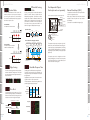
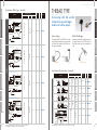
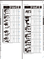
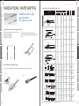
1
Fiber sensor
NF Series
Amplifer for Fiber sensor
Amplifiers
Digital high speed fiber Sensor
D3RF series
Digital fiber Sensor
D2RF series
Fiber Sensor
BRF series
THE BEST FIBER SOLUTION
Technical data are available at ;
http://www.optex-fa.com
● Specifications are subject to change without prior notice.
● Specifications and technical information not mentioned here are written in Operation Manual. Or visit our website for details.
● All the warnings and cautions to know prior to use are given in Operation Manual.
600-8815 Kyoto, Shimogyo, Chudoji Awata 91, Japan
TEL. +81-(0)75-325-2920 FAX. +81-(0)75-325-2921
http://www.optex-fa.com
74585-01-QL0808
Fiber optic cables for the most demanding applications.
Special requests for custom made fiber cables are welcome.
Introduction
AMPLIFIERS and
FIBER SENSORS
Introduction
Amplifiers
D3RF series
09
D2RF series
13
BRF series
20
Application Index
03
Alphabetical Index
05
NF series
23
Fiber units
Notes
01
84
02
Application Index
Application Index
Retro-reflective
47
Convergent beam
49
Limited diffuse
57
Narrow beam,wafer mapping
63
52
Heat resistant (200o∼300o)
72
Flexible
Flexible
Various Shape for mounting
A complete fiber optic sensor consists of the amplifier and a fiber optic cable.
The fiber optic cable is chosen based upon the specific application.
Optex-FA offers more than 80 different cables in both Thru-beam and Diffuse sensing modes.
Screen beam array
Amplifiers
Various Detecting Scheme
Various Shape for mounting
Amplifiers
Fiber unit NF series
Thread type
28
Sleeve-straight
34
Sleeve-side
37
Cylindrical type
31
Heat resistant (up to 130o)
66
Heat resistant (up to 200o)
68
Chemical resistant
75
Vacuum resistant
77
Environment-resistant
25
Liquid
Easy mounting
Various Detecting Scheme
Environment-resistant
Liquid
Environment-resistant
Various Detecting Scheme
Various Shape for mounting
Flexible R1mm
41
Flexible R2mm
45
Water, water level
79
Lens for thru-beam fibers
82
Notes
39
Extension lens
Notes
Flexible R4mm Bend-tolerant
Liquid
Extension lens
Extension lens
Flexible
03
04
AMPLIFIERS for NF series
Various Shape for mounting
Various Shape for mounting
Amplifiers
Amplifiers Introduction
Amplifiers
Amplifiers D2RF series
High speed digital fiber sensor
D3RF series
09
Flexible
Various Detecting Scheme
Various Detecting Scheme
Flexible
All amplifiers are available in Cabled or M8 QD versions and are offered with a choice
of NPN or PNP outputs.
Digital fiber sensor
13
Environment-resistant
Environment-resistant
D2RF series
Fiber sensor with trimmer
Extension lens
Notes
Notes
Extension lens
Liquid
20
Liquid
BRF series
07
08
Amplifiers D3RF series
Amplifiers D3RF series
High speed digital fiber sensor
Amplifiers
Fastest in the class Digital fiber sensor
No.1
16µs(1-HS mode)
22µs(inter-connection type)
5mm wider display than conventional D2RF.
7 segment with high brightness LED for better
visibility.
More than 2 sec. pressing the button for teaching.
Higher functionality is in deeper setup layer. These
prevent miss-operations.
D2RF
High speed processor
“FAntron DUO”
Pressing
2sec.
for teaching
Increased sensitivity by
original emitting method.
Highly efficient collective lens
High power efficient LED
Display can be changed to percentage (0~100) by
simple single action with buttons. Easy to recognize
when the level changes.
Dual “ASC”
Malfunction
Sensing level
Threshold
Fiber unit: NF-DH01 (diffuse/heat resistant 180℃)
Automatic re-adjust
after cleaning up
Extension lens
2.8 times
Threshold level is adjusted optimized
level automatically according to
sensing level continuously.
Adjustable hysteresis
ECO mode
Our original technology “FALUX” stabilizes LED
brightness by adjusting LED current even under
fluctuation of LED temperature after power up.
Hysteresis can be adjusted from 1% to 40% as you
like. This enables flexible setup of sensitivity according to various object condition.
It has ECO mode that enable power saving by
making sub-display (green) OFF and darken maindisplay (red).
50
60
Time [min]
LED cathode temp.
Temperature
Relative brightness
40
70
60
50
40
30
20
10
120.0
100.0
80.0
60.0
40.0
20.0
0.0
0
10
20
30
40
Time [min]
Relative brightness
50
60
%[ ]
30
%[ ]
℃[ ]
20
450
NF-DR01(M6 R2mm)
350
NF-DH01(180℃)
450
1200
1100
1250
4000
4000
4000
NF-TB01(M4 coaxial) 1800
NF-TR01(M4 R2mm)
800
NF-TH02(180℃)
1000
ratio
(times)
2.7
3.1
2.8
2.2
5
4
With FALUX
120.0
100.0
80.0
60.0
40.0
20.0
0.0
℃[ ]
Temperature
Without FALUX
NF-DB01(M6 coaxial)
(mm)
D3RF (7-EL mode)
Brightness stabilizing function
“FALUX”
70
60
50
40
30
20
10
D3RF
(mm)
Liquid
Liquid
Sensing level changes when light path
got some contamination and then it
works wrongly . It needs re-teaching.
Notes
D2RF (long mode)
Time
Time
09
(Inter-connection)
Easy to recognize when it changes.
D2RF
Fiber unit
Extension lens
Threshold
From 4 digit to %
Sensing distance comparison
ex.) D3RF-TDN (single, 2 output)
Detecting parts leads
Detecting sheet objects
Standard mode :
39mA max.
-30%
Notes
Sensing level
Sensing level
Sensing level
Fixed thershold
Utilizing our original pulse emitting method, High
power LED and efficient collective lens, it can receive
enough light to realize around 3 times longer sensing
distance for diffuse and 5 times longer sensing
distance for thru-beam sensing.
Environment-resistant
Detects light degradation made by some dust and
adjusts the brightness. It re-adjusts threshold automatically after cleaning up so no need re-teaching.
Super sensing distance
Diffuse
Dual “ASC” for easy maintenance
100% display for better
recognition of change
Relative brightness
Environment-resistant
D3RF
10
Various Detecting Scheme
5mm wider !
Various Detecting Scheme
Originally developed super high speed processor
“FAntron DUO” enables fastest speed in the class 16
µs (1-HS mode). It can detect over 30,000 pieces per
second. Maximum speed of inter-connection type is
22us. It can prevent cross talk up to 2 units.
Flexible
Easier operation
Flexible
Widest display in the class
0
Various Shape for mounting
16µsec response, long sensing distance,
finest in digital-class amplifiers.
Thru-beam
Various Shape for mounting
Amplifiers
D3RF series
ECO mode :
28mA max.
10
Amplifiers D3RF series
It can prevent cross talk
by shifting emitting timing.
You can connect up to 12
units when the setup is
standard mode. You can
connect up to 16 units
when the setup is ECO
mode.
Various Shape for mounting
Maximum inter-connect units
D2RF
D3RF
8 units
16 units
(cross talk prevention:
OFF or ECO mode)
Model
1 output type(NPN/PNP)
2 output type(NPN/PNP)
1 output type(NPN/PNP)
M8 QD
type
2 output type(NPN/PNP)
Light source
Response type (mode)
Sensitivity adjust
Cable
type
1 output type
2 output type
Digital display
Indicator
Control output *2
Easy setup
Various Detecting Scheme
Slave side
Timer
Master side
Flexible
You can copy setup from master
side to slave side. Zero reset and 1
point teaching is available all
together.
Input
Copying setup, Zero reset, 1 point teaching
Output mode
Cable / Connector
Insulation impedance
Power supply
Power consumption
Ratings
(normal mode)
Power consumption
(saving mode)
Conformity
Operating temp./humid.
Environmental illuminance
Vibration resistance
Shock resistance
Protection category / Material
Weight
Bracket
Amplifiers
You can connect up to 16 units without any wiring.
Specifications
Inter-connection type - master Inter-connection type - slave IR type
Single type
D3RF-TMN / TMP
D3RF-TSN / TSP
D3IF-TN / TP
D3RF-TN / TP
D3RF-TDMN / TDMP
D3RF-TDSN / TDSP
D3RF-TDN / TDP
D3RF-TCN / TCP
D3RF-TCMN / TCMP
D3RF-TCSN / TCSP
D3IF-TCN / TCP
D3RF-TCDN / TCDP
D3RF-TCDMN / TCDMP
D3RF-TCDSN / TCDSP
IR LED(1,450nm)
Red LED
*1(1-HS)
16µs/22µs , 70µs(2-FS),250µs(3-ST),500µs(4-LG),1ms(5-PL), 2ms(6-UL), 8ms(7-EL)
Teaching, Manually adjusting
1 Output indicator (Orange)
2 Output indicator (Orange)
7 segment 8 digit display (red: 4 digit, green: 4 digit)
NPN or PNP open collector
100mA/DC30V max. Load: 100mA max. Residual voltage: 1.8V max.
Teach-in *3 , Emitter stop input, Synchronous input, Counter reset input (only for 2 output type)
ON delay, OFF delay, One shot, ON+OFF delay, ON delay + One shot
0.1∼9.999ms
Light ON / Dark ON switching is available in setup
2m (single type and interconnection master type : ø3.8mm , slave type : ø2.8mm), or M8 connector
20MΩmax. (DC500V)
DC12∼24V±10%including ripple
Various Shape for mounting
Cross talk prevention
Flexible
Easy installation
36mA max. (1 output type), 39mA max. (2 output type) / DC24V
25mA max. (1 output type), 28mA max. (2 output type) / DC24V
*4
(Eco All mode)
CE, IEC
-25∼+55℃ / 35∼85%RH without condensation
Sunlight: 10000 lux max., Incandescent lamp: 3,000 lux max
10~55Hz 1.5mm swing X,Y,Z 2hours
50G (500m/s2) X,Y,Z 3times
IP50 / Case: PPE, Cover: PC
Approx. 71g including cable
BEF-WLL170 Various Detecting Scheme
Amplifiers
Amplifiers D3RF series
Circuit diagram
NPN output
Less connection
PNP output
ex.) 18 wires for 16 units inter-connection (1ch output)
protection
protection
Control output 1
Gray
Control output 2
White
protection
protection
External input
White
External input
Black
Control output 1
Gray
Control output 2
Blue
Liquid
Blue
load
D3RF-TMN/TDMN (master)
D3RF-TSN/TDSN (slave)
Black
load
D3RF-TN/TDN
D3IF-TN
main circuitry
Interconnection type
Brown
Liquid
Single type
load
load
Brown
Dimensions
Environment-resistant
output
output
output
output
output
output
output
output
output
output
output
output
output
output
Interconnection type
main circuitry
Environment-resistant
output
output
*1 Single type: 16us. When cross talk prevention mode is activated on interconnection type, it’s 22us.
*2 Threshold, Timer and Light ON/Dark ON of control output for 2 output type can be setup individually.
*3 External teaching mode is done based on the mode that is set on sensor (default is 1 point teach).
*4 When you use 1~3 pieces interconnected including master.
Please use output less than 50mA each and in -25~+50oc when you use 4~8 pieces interconnected including maste
Control output 2
This is only for slave type.
Notes
up to
Cable
11
up to
Cable
Extension lens
Control output 1
0V
12~24V DC
Options
(master)
(slave)
End plate
JCN-S : 2 meter
JCN-5S : 5 meter
JCN-10S : 10 meter
: 2 meter
JCN-L
JCN-5L : 5 meter
JCN-10L : 10 meter
BEF-EB01-W190
JCN-S:M8 Straight type
JCN-L:M8 L-shape type
Notes
Extension lens
Output : NPN/PNP or Alarm
Input : External teach or Counter reset
12
Amplifiers D2RF series
Amplifiers D2RF series
Digital Fiber Sensor
Received Light Level and Threshold Setting
If your application is around
water or high humidity.
There is a model of the
D2RF-T series with an IP66
rating.
CH2
Various Detecting Scheme
Environment-resistant
Two points Teaching
Standard detection mode for
Diffuse type sensing.
It is possible to make fine adjustments.
Transparent / Glass Teaching
Ideal for the detection of glass,
film, plastic or any transparent
material.
Zone Teaching
Similar to Area Teach Mode.
This is useful if the conveyor
moves closer to and farther from
the sensor. An area +/- 10% of
the teach point can be detected.
V42
Reflector
Near
Teach-in point
Far
10%
10%
detectable
area
Liquid
Our engineer "SAM" designed this function. The
lens and/or reflector may be contaminated over
time. The D2RF amplifier monitors the change in
light level and automatically resets the threshold
value.
Extension lens
After cleaning off the lens / reflector it used to be
necessary to reset the threshold setting. The
D2RF does not require this step. Simply clean off
the lens and wait three seconds without a target
present. The sensor will automatically reset the
threshold level for the change. This is how the
SAM circuit works.
Notes
After cleaning the incoming light level will
increase suddenly. The SAM circuit computes
the preset threshold based on the increase in
light intensity.
This function is available only in Transparent
Detection Mode.
Threshold
Malfunction
Time
D2RF series
SAM Circuit
Returned light level
Returned light level
Threshold
Automatic
computing
SET/RUN
Both outputs can be set to
operate at this speed.
This response time is available in 5 of the teach
modes.
LED Power adjustment 3 step adjustment of LED
emitting power.
A highly reflective target will cause the amplifier to
saturate making adjustment difficult. This can also
happen if the fiber cable is mounted too close to the
target.
In situations where the amplifier is saturated due to
excessive reflected light, the power level of the emitting LED can be decreased to 50 or 25 percent.
Power setting
The threshold will auto-matically return to the preset level after the lens is
cleaned off.
Mode
A conventional 3 element LED will lose brightness
over time. This results in a decrease in sensitivity in
the sensor. Optex FA's new D2RF uses a 4 element
LED to provide long service life. The Green LED type
D2GF uses a "Glan N2" LED, which offers the best
performance for Mark Detection with a Green LED
light source.
Contamination on the lens will eventually cause the sensor to malfunction.
Returned light level
Threshold
60 micro second high speed response.
Conventional Sensor
Returned light level
Light level
Long Term Stable Detection.
SAM Circuit - The ASC function (Auto Sensitivity Control)
13
Select/Adjust Teach-in / CH
CH1
100%
50%
25%
Various Shape for mounting
IP66 and IP50, two types.
Time
Flexible
Two four digit display's.
V42
Reflector
Single point Teaching
Set without a target present.
Time
Various Detecting Scheme
Full automatic Teaching
Set while the equipment is
operating.
APC
Conventional model
Environment-resistant
Flexible
Full Power Teaching
Standard detection mode for
Thru-beam type sensing but
applicable for retro-reflective
sensing also.
Level of
light emission.
Cross Talk Prevention
The amplifier frequencies
are
automatically
set
between the Master and
Slave units. Cross talk
prevention is possible for
up to 4 amplifiers.
Liquid
6 teach method for individual applications.
Level of
light emission.
Extension lens
Digital Fiber Amplifier with Two Independent Outputs.
High speed 60 micro second response.
The APC function ensures precise sensing even
when there are changes in the temperature or
environmental conditions.
APC maintains a constant power level of light emission by regulating the current flow into the light emission element. The APC function can be turned On
and Off.
Automatic Tuning
This provides a way to boost or dampen the excess
gain level of the amplifier in poor sensing conditions
(low light level, low sensitivity or saturating condition).
Automatic Tuning is ideal when you need a little bit
better excess gain level, or when detecting a dark
object with diffuse reflective fiber cables.
Notes
Various Shape for mounting
Amplifiers
D2RF series
Amplifiers
APC Function (Auto Power Control)
Time
14
Amplifiers D2RF series
output
2
1
output
output
Operation Flow:
Reflection
Reflection gap
between Master
and Slave
Flexible
Output
Normal position
An output comes only when the preset
numbers are counted. (Max 9999)
Various Detecting Scheme
3
Master
Slave
1000
200
800
Teach-in
Value
The Slave
advises reflection quantity
from conveyor surface
Master
Slave
300
target difference
2
1
M
S
800
Master
Slave
900
100
It's traceable !
M
S
800
It's traceable !
M
S
The same gap has been maintained.
output
Amplifiers
Control output 2
Output : NPN/PNP or Alarm
Input : External teach or Counter reset
The operation of each output can be set to Light-On /
Dark-On. Also, the Threshold level, Timer settings, etc.
of each output can be set independently. The Analog
output type (D2RF-TAN/P) provides a 4 ~ 20 mA (gray
wire) analog output and a NPN (or PNP) digital output
(black wire).
The sensor output triggers when there is a sudden
increase or decrease in the light level. This is ideal
for sensing objects without being influenced by a
dusty environment.
Falling Edge Sensing Mode
Selectable Response Time
The Response time will affect the sensing distance.
The D2RF-T has three choices (Long, Standard, and
Fast), select the response time based on the required
sensing distance.
Long Mode boosts the power for the maximum sensing distance with a 2 msec. response time.
The Fast Mode has a reduced sensing distance but
provides high speed 60µsec. response.
Liquid
Environment-resistant
Edge Sensing
Liquid
0V
The second output can be configured as an Alarm
output (self-diagnostic). It can also be set to operate
as an External Teach Input or Counter Reset Input if
the Counter function is being used.
threshold
Rising Edge Sensing Mode
Control output 2
Output : NPN/PNP or Alarm
Input : External teach or Counter reset
Control output 1
0V
12~24V DC
Conveyor bumps
downward
Conveyor bumps
upward
1100
Control output 1
Display
How to follow the changing condition!
Counter Mode:
Protection
Circuit
Gray ❷
Blue ❸
Computing
The Master
threshold
Protection
Circuit
Reflection
Display
Black ❹
12~24V DC
Environment-resistant
3
Brown ❶
It is possible to have a Remote Teach Input if the CH2
output is re-assigned as an input.
When using the Remote Teach with Interconnected
amplifiers all units will perform the Teach function
simultaneously.
(This function is not available for Analogue Type)
Flexible
An output comes as the sensor counts.
The 2nd output can be configured as an external Teach input.
External Teach Input (CH2)
Various Detecting Scheme
Normal Mode:
A bumpy conveyor always makes stable detection
difficult. The D2RF-T solves this problem with the
Differential Sensing Mode. The Master and Slave
amplifiers will calculate the difference between the
reflection from the background and the target (see
picture below). No matter how much the surface of
the conveyor moves up and down the D2RF-T can
follow the change and reliably detect the target.
Load
Various Shape for mounting
The D2RF amplifier features a built-in counter. This
makes it convenient to count parts, for example 10
pcs. in a bag. The output turns on once the sensor
has counted the desired quantity. Simply program in
the number of parts to count.
Load
Amplifiers
Counter Mode
Two Independent Outputs.
Each output can be set separately.
Main circuit
Differential Sensing
Mode
Various Shape for mounting
Amplifiers D2RF series
(Response)
Long mode
Returned light level
Notes
Zero Reset :
Shifted value : 1000
Returned light level
Threshold
Standard mode
Fast mode
250μsec
*Example: NF-DB01
60μsec
100mm
250mm
450mm
(Distance)
Long mode
Standard mode
Notes
Extension lens
The sensor display can be reset to zero. This is
useful for adjusting the display's of the Master and
Slave units to read the same. It is also good to set
the value to zero when the light is interrupted.
2msec
Extension lens
Zero Reset
Threshold
Fast mode
15
16
Amplifiers D2RF series
Amplifiers D2RF series
11
7.5
10.5
IP66 type
72
2.55
1.9
5.45
Maximum
2- R2.1
φ4.2
φ8.6
34.8
16.25
2- R2.1
φ4.2
20.45
29.45
55.4
7
φ8.65
57.05
・D2RF-2TC 3/4
・D2GF-2TC 3/4
10.4
・D2RF-TC 4
・D2GF-TC 4
10
Flexible
10.4
10.45
7
φ8.6
10
4.3
18.8
27.8
5.8
5.6
4.3
16.3
9.5
8
2-φ2.4
33.3
φ7.2
34.8
9.4
8
32
2-φ2.2
M8 QD 4pin, NPN / PNP
Maximum
aperture 200
aperture 150
6.2
Interconnection model
11
・D2 F-TS
・D2 F-TSC 4
33.4
7.8
11
51.9 (Joint)
3
68.9
1.9
10.5
Maximum
3
68.9
1.9
Maximum
10.4
9.15
18.8
Cable : φ2.8 2core 2m
36.6
φ8.65
Cable : φ3.8 4core 2m
36.6
φ7.2
32
9.4
9.4
18.8
8
φ7.2
8
32
2-φ2.2
aperture 150
2-φ2.2
10.4
Various Detecting Scheme
aperture 150
12.2
10.5
33.4
7.8
・D2 F-TM
・D2 F-TMC 4
10.4
・M8 Connector type
10.5
3
68.9
Maximum
aperture 200
φ8.6
34.8
8
33.3
16.25
Options
20.45
29.45
10
7
2- R2.1
φ4.2
End plate
JCN-S : 2 meter
JCN-5S : 5 meter
JCN-10S : 10 meter
: 2 meter
JCN-L
JCN-5L : 5 meter
JCN-10L : 10 meter
BEF-EB01-W190
JCN-S:M8 Straight type
JCN-L:M8 L-shape type
57.05
Notes
Notes
Extension lens
2- R2.1
φ4.2
D2RF-TMN / TMP
D2GF-TMN / TMP
NA
D2RF-TMCN4 / TMCP4
D2GF-TMCN4 / TMCP4
NA
D2RF-TSN / TSP
D2GF-TSN / TSP
NA
D2RF-TSCN4 / TSCP4
D2GF-TSCN4 / TSCP4
NA
Red LED
Green LED
Red LED
60 micro sec (Fast mode ), 250 micro sec (standard), 2.0 ms (Long distance)
APC / ASC
3 steps ; 100%, 50% and 25%
On delay/Off delay /One shot, 1-9,999msec (1msec increment)
Teach-in + fine adjustment
Output (orange) : 1CH / 2CH common
Output (orange)
7 segment LED, 4 digits in Red, 4 digits in Green
Full Power / One point / Two points / Full Automatic / Differential / Zone / Transparent
2CH, NPN or PNP open collector, DC30V, 100mA Max
1CH, NPN or PNP
NA
4-20mA, Resolution 0.1%FS
Up to 16 sets
Up to 4 sets
Light on / Dark on selectable
Long Distance Mode, Standard, Fast mode,
Regular dislay plus ; bar, %, eco (off, run mode only)
Teaching / Counter Reset
DC 10-24V +/- 10% ripple
45mA Max (24V)
Reverse Polarity, Overcurrent, Short circuit
100m sec
−25 to 55℃, 35 to 85% RH
−40 to 70℃, 35 to 85% RH
Sunlight 10,000 lux, High Frequency Lamp 3,000 lux
IEC, IP50 (except Stand-alone IP66 types)
IEC, CE
IEC 68, 50G
Cable type 21g, M8 connector type 23g
Response time (Standard), Output (Light On), Timer (OFF), APC (OFF),
Extension lens
55.4
7
4.3
10
9.5
16.3
4.3
18.8
27.8
5.8
φ7.6
34.8
8
32
9.4
5.6
Liquid
2-φ2.4
D2RF-TAN / TAP
NA
D2RF-2TAN / 2TAP
NA
NA
5.45
Maximum
aperture 150
2-φ2.2
D2GF-TN / TP
D2GF-TCN4 / TCP4
D2GF-2TN / 2TP
D2GF-2TCN4 / 2TCP4
D2GF-2TCN3 / 2TCP3
Independent settings between CH1 and CH2 are possible at Threshold setting. Timer setting and Light/Dark setting.
Ambient Temperature is limited up to 50°c when amplifires are connected in parallel over 4 pcs.
72
2.55
2.6
M8 QD 3pin, NPN / PNP
Interconnection Type
Master
Cable type NPN / PNP
unit
M8 QD 4pin, NPN / PNP
Slave
Cable type NPN / PNP
unit
M8 QD 4pin, NPN / PNP
Light source
Response time
Auto control system
LED Power control
Timer functions
Sensitivity adjustment
Output indicator
Digital indicator
Teach-in mode
Control output
Analogue output
Parallel installation
Crosstalk prevention
Operating mode
Sensing mode
Display
External input
Supply voltage
Power consumption
Circuit protection
Warm-up time
Operating temp / humidity
Storage temp / humidity
Environmental illuminance
Protection category
Comformity
Shock resistance
Weight
Factory default settings
D2RF-TN / TP
D2RF-TCN4 / TCP4
D2RF-2TN / 2TP
D2RF-2TCN4 / 2TCP4
D2RF-2TCN3 / 2TCP3
11
・D2RF-2TA
M8 4poll Connector
32.9
15
33.4
7.8
・D2RF-TA
14
7.5
Analogue model
10.5
Environment-resistant
11.2
Cable type NPN / PNP
Analogue
Various Shape for mounting
68.9
Mark sensor
Flexible
3
M8 QD 4pin, NPN / PNP
Standard
Various Detecting Scheme
10.5
Stand-alone Type
IP50 type Cable type NPN / PNP
32.9
15
・D2RF-2T
・D2GF-2T
7.8
・D2RF-T
・D2GF-T
Various Shape for mounting
Model
33.4
14
Environment-resistant
Stand-alone model
Amplifiers
Specifications
Liquid
Amplifiers
Dimensions
17
18
Amplifiers D2RF series
Amplifiers BRF series
Fiber Sensor
Control output 1
Gray ❷
Control output 2
/ External Input
Protection
Black ❹
Control output 1
Load
circuit
Gray ❷
Load
circuit
Protection
Blue ❸
Control output 2
/ External Input
Blue ❸
0V
Part Identification
Gray ❷
Control output 2
/ External Input
Load
circuit
Blue ❸
Environment-resistant
0V
Black ❹
Control output 1
Load
circuit
Gray ❷
Protection
Potentiometer
Fiber insertion indicator
Control output 2
/ External Input
・Power wires (Brown ❶. Blue ❸) are not attached to Handset unit,
both on cable and connector type.
Blue ❸
0V
Long distance sensing
Analogue model
NF-DT01
Control output
Blue
Black
Load
circuit
Control output
Dimensions
Gray
0V
Gray
Cable Type Stand-alone
Analog output
Analog output
Analog GND
Analog GND
M8 Connector Stand-alone
35.5
74.9
80.9
18.9
10.5
11.5
36.6
Notes
8
10.7
12.5
Extension lens
D.ON
OFF
Blue
0V
BRF-HN or HP
High Speed type
long distance lens
12∼24V DC
Protection
Black
φ0.015mm
NF-TK77
(+NF-TA01)
Brown
12∼24V DC
Main circuit
Main circuit
Load
circuit
Liquid
High Speed response
Min object φ0.015mm 50µsec
PNP output
Brown
Protection
Sensitivity indicator
4m distance !!
NPN output
<4 Pin configuration>
① DC10∼30V
②③ 0V
④ Control Output
19
firmly inserted
Environment-resistant
Control output 1
12∼24V DC
Protection
not inserted
Liquid
Protection
Protection
Black ❹
Light ON / Dark ON
Fiber lock
Extension lens
Load
circuit
Output indicator(orange)
Brown ❶
12∼24V DC
OFF delay
36.6
18.9
Notes
Main circuit
Various Detecting Scheme
Load
circuit
Stable incident indicator(green)
Max
Brown ❶
PNP output
Main circuit
NPN output
Various Detecting Scheme
Interconnection model
SENS.
Flexible
0V
・3 models: Standard, High Speed, Mark Detection.
・High Speed type (50 micro sec) and Green LED
type for Mark Sensing.
・Crosstalk prevention. IP66 protection.
・10 turn adjustment potentiometer for fine tuning.
Min
Protection
Protection
Black ❹
12∼24V DC
Various Shape for mounting
Load
circuit
Brown ❶
12∼24V DC
OFF DLY
Main circuit
Load
circuit
PNP output
Flexible
Brown ❶
Main circuit
Various Shape for mounting
NPN output
Amplifiers
BRF series
Stand-alone model
L.ON
Amplifiers
Circuit diagram
79.1
85.1
(Unit : mm)
20
Amplifiers BRF series
Notes
φ2.2
①
M2.6 P=0.45
15
28
15
+100
1000 0
: 2 meter
JCN-L
JCN-5L : 5 meter
JCN-10L : 10 meter
JCN-S:M8 Straight type
JCN-L:M8 L-shape type
4N
54N
47N
43N
33N
Environment-resistant
Infrared LED
8N
Liquid
1msec
23N
Extension lens
250 ms
1.8V/100mA max.
Green LED
77N
Notes
250 ms
50 µsec
NPN or PNP Open Collector 100mA/DC30V max.
Red LED
Green
Orange
10 turn
Dark On/Light On selectable
Off Delay 40msec fixed
DC10 ∼ 30V Inc. 10% ripple
25mA/30V (30mA/30V Interconnection type)
10,000 lx min.
3,000 lx min.
−25 ∼ +55oC
35 ∼ 85%
−40 ∼ +70oC/35 ∼ 95%
Min. 20MΩ/DC500V
CE regulation
Level 3
±5% max.
−10% max./1000 h
10 ∼ 55Hz, 1.5mm
500m/s2
IP66
IP50
100ms max.
Overcurrent (output), Reverse Polarity, Short Circuit
Class 3
PBT G10
PC
W10.5 x D80 x H35.5mm
cRU recognition
CE sign
88N
25 50 75 100 25 50 75 100 25 50 75 100 25 50 75 100 25 50 75 100 25 50 75 100 25 50 75 100 25 50 75 100 25 50 75 100
33N
BIF-WN / WP
BIF-CWN / CWP
30mm Diffuse
100mm Thru-beam
43N
Moisture type
BGF-N / P
BGF-CN / CP
40mm
47N
Mark type
BRF-HN / HP
BRF-CHN / CHP
50mm
54N
High speed type
BRF-N / P
BRF-CN / CP
150mm
4N
Standard type
Stand-alone
8N
Model
23N
Environment-resistant
Liquid
Extension lens
Notes
④ : Control output
Sensing Chart by colours ( BGF series Mark Sensor )
Specifications
Cable type
M8 QD type
Sensing distance 90% 250mm×200mm
(*1)
DK-06 Diffuse Fiber
Response time
Control output
Light source
Stable output
LED Indicator
Output
Potentiometer
Operating mode
Timer
Supply voltage
Power consumption
Sunlight
Environmental
Incandescent lamp
illuminance
Operating temp
Operating humidity
Storage temp / humidity
Insulation resistance
Conformity
EMC Test
Failen Test (house test)
Temperature drift
LED Compensation ratio
Vibration resisitance IEC68
Shock resistance IEC68
Protection
Stand-alone
category
Interconnection
Warm-up time
Circuit protection
VED classification
Housing
Material
Cover
Dimensions
UL
Regulation
CE
②: -
JCN-S : 2 meter
JCN-5S : 5 meter
JCN-10S : 10 meter
77N
Various Detecting Scheme
10
10
<4 Pin configuration>
① : DC10〜30V
③ : 0V
Flexible
φ5
Fiber Optics
bundle diameter
φ1.5
3
0V
φ2.2
Not Metal
φ4
φ5
Special Tube
SUS 303
Control output
Options
M4 P=0.7
Thru-beam Type
③
10〜30V DC
Various Detecting Scheme
NF-TW01
SUS 303
0V
② ④
Fiber Optics bundle φ1.5
( Black,④ )
( Blue,③ )
( Blue,③ )
Transmitter
25
+100
1000 0
Protection
circuit
Control output
15
12
22
Flexible
Protection
circuit
88N
3
( Black,④ )
25 50 75 100 25 50 75 100 25 50 75 100 25 50 75 100 25 50 75 100 25 50 75 100 25 50 75 100 25 50 75 100 25 50 75 100
SUS 303
Fiber Optics bundle φ2
φ2.2
Not
Metal
10〜30V DC
Receiver
φ10
Special Tube
SUS 303
φ4
φ5
φ4
Various Shape for mounting
M6 P=0.75
( Brown,① )
( Brown,① )
15
Various Shape for mounting
25
Main circuit
60
LOAD
20
Diffuse Type
Main circuit
NF-DW01
PNP output
LOAD
Amplifiers
NPN output
Amplifiers
Circuit diagram
Dimensions
: Stable sensing
: Not recommended
* 1 See NF series Fiber optics.
21
22
Various Shape for mounting
Various Shape for mounting
Amplifiers
Fiber units Introduction
Amplifiers
Fiber units Introduction
39
Various Detecting Scheme
47
Environment-resistant
66
Liquid
79
Extension lens
82
Various Detecting Scheme
Flexible
Environment-resistant
25
Extension lens
Notes
Notes
Extension lens
Liquid
Various Shape for mounting
Liquid
Environment-resistant
Various Detecting Scheme
Flexible
A complete fiber optic sensor consists of the amplifier and a fiber optic cable.
The fiber optic cable is chosen based upon the specific application.
Optex-FA offers more than 80 different cables in both Thru-beam and Diffuse sensing modes.
Flexible
Fiber unit NF series
23
24
Various Shape for mounting
Various Shape for mounting
Sensing distance (unit=mm)
D3RF
1,770
5-PL
(20)
14
φ2(PVC)
φ1.3
φ2.4 case
prism
multi core fiber
(poly carbonate)(Acrylic)(core wire:Acrylic, outer sheath:Polyethelene)
exterior of fiber
φ1
1.05
optical axis
1.75
0.5
exterior of fiber
φ1
2000
2,300
5-PL
7.5
φ1.3
0.5
11
Various Detecting Scheme
φ1.5
You can choose from Head ON, Side ON and Flat ON. You can also choose flexibleness
from R1mm and R4mm as well
3-ST
1,150
Environment-resistant
Sensing distance (unit=mm)
Value in parenthesis is the Minimum detectable object size. (copper wire)
Sensing head
Red LED for general purpose
D3RF
Flexible Head ON Free cut
(20)
400
7
φ2(PVC)
φ1
multi core fiber
(core wire:Acrylic, outer sheath:Polyethelene)
1
2.3
multi core fiber
φ0.075×151
φ1.3
3,580
Std
2-φ2.2
φ2.5(PVC)
7.5
1.75
3,060
3-ST
1,980
2,700
1,600
Fast
1,600
ー40∼60
R=1
NF-TR11
850
2-FS
Liquid
Thru-beam
Extension lens
3
2000
11
(20)
multi core fiber
φ0.075×151
3,600
2-φ2.2
optical axis
5.5
1.75
Notes
5
2
10
3.5
1.2
2.5
φ2.5(PVC)
lens
4-LG
3,150
3-ST
2,000
optical axis
7
1000
φ1
φ2
(PVC)
multi core fiber
prism
(Acrylic)(core wire:Acrylic, outer sheath:Polyethelene)
multi core fiber φ0.0375×151
exterior
of fiber
8
Long
2,700
Std
1,500
Fast
1,300
ー40∼60
R=1
NF-TR12
2.5
exterior 8
of fiber
2.5
4-LG
Std
1-HS
100
Operating humidity is 35~85%RH. Please use in 0~40 deg.C when it’s 85%RH
2-FS
600
NF-TE04
350
220
ー40∼60
R=1
NF-TE01
2-φ2.2
7.5
1,100
ー40∼60
R=4
NF-TR06
1,100
ー40∼60
R=4
NF-TR05
300
ー40∼60
R=4
NF-TE05
200
Long
3,580
2,700
3,060
1,600
3-ST
1,980
2-FS
Std
Fast
850
1,400
1
11
2000
φ1.25
optical axis
2.2
optical axis
7.5
3,600
6-UL
3,600
5-PL
Long
4-LG
Std
3,600
3,150
3-ST
2-φ2.2
2,000
2-FS
2,700
1,300
Fast
600
1,100
1-HS
320
7-EL
optical axis
11
1
1,800
2000
6-UL
1,510
2.4
1.75
φ0.25×7
※Emitter&Receiver are symmetrical.
5-PL
Long
4-LG
Std
1,320
3.9
φ1.25
optical axis
Fast
5-PL
7-EL
2
exterior 8.5
of fiber
3,600
4-LG
3.5
3
Long
310
2000
φ1.25
Flexible Flat ON Free cut
5-PL
550
R=1
250
500
6-UL
2-FS
1
※Emitter&Receiver are symmetrical.
1,190
3-ST
ー40∼60
Fast
1-HS
1.75
540
850
630
450
3,600
1.75
φ0.25×7
1-HS
980
3-ST
750
130
3.5
1,000
1,200
1,120
Std
960
7-EL
3
7-EL
φ2.2、φ3.6spot facing depth1.4
Inner pipe(SUS)
(20)
Long
4-LG
390
Flexible Side ON Free cut
2-FS
φ1.5
case
(poly carbonate)
1.05
optical axis
exterior
of fiber φ0.5
25
φ1.3
7.5
Flexible Flat ON Free cut
0.5
5-PL
5-PL
1-HS
0.9
optical axis
6-UL
3.5
2
φ1.3
φ0.25×7
3,600
3,600
280
55
2-FS
1,260
1.6
11
optical axis
1,350
7-EL
12
190
1,090
2
530
exterior
of fiber 2.5
φ1
8
NF-TE02
6-UL
multi core fiber
(core wire:Acrylic, outer sheath:Polyethelene)
3
1-HS
Flexible Side ON Free cut
R=1
6-UL
Long
5-PL
ー40∼60
1,340
φ2(PVC)
multi core fiber φ0.075×151
Fast
7-EL
2000
2.9
3-ST
250
120
36
(20)
7
Std
300
1-HS
φ3.2、φ5.6spot facing depth2.2
Inner pipe(SUS)
optical axis
Long
4-LG
120
11
3.5
5-PL
350
Flexible Head ON Free cut
3,600
4-LG
optical axis 2
exterior
of fiber
110
330
6-UL
(20)
2.5
optical axis case
(poly carbonate)
φ1
3,600
3.5
8
Part Number
φ2.4
NF-TR13
430
1000
φ2.2、φ3.6sspot facing depth1.4
Inner pipe(SUS)
6-UL
2000
11
optical axis
BRF
Radius
(mm)
7-EL
12
exterior
of fiber lens
φ1
2.5 3
D2RF
Operation
temperature
(℃ ∼℃)
Thru-beam
Specifications (Thru-beam Type : Standard)
R=1
7-EL
0.6
multi core fiberφ0.0375×151
14
650
Fast
220
10
3.5
3.5 3.5
7
Std
1-HS
Flexible Head ON/Side ONswitchable type Free cut
1
1.05
ー40∼60
Long
1,200
650
optical axis
φ0.5
4-LG
2-FS
optical axis case
(poly carbonate)
exterior
of fiber
2,010
1,710
φ2.5(PVC)
Flexible Head ON/Side ON switchable type Free cut
10
500
350
6-UL
multi core fiber φ0.075×151
5
NF-TE03
2,450
※Emitter&Receiver are symmetrical.
Head ON, Side ON, Flat ON fixed type
R=1
Fast
7-EL
optical axis
2-φ2.2
optical axis
2
880
2-FS
Std
Flexible
(20)
3.9
0.5
1.05
500
3-ST
Liquid
Flexible
You can switch Head ON and Side ON changing
fiber position.It helps reducing inventory and
flexibleness R1mm helps you to mount easily.
1,350
170
12
2.2
8.5
900
4-LG
1-HS
Flexible Flat ON Free cut
Head ON/Side ON switchable type
ー40∼60
Long
1,540
520
multi core fiber φ0.075×151
3
450
6-UL
Inner pipe(SUS)
3.5
7
1,890
Various Detecting Scheme
3.5
7-EL
2000
φ3.2、φ5.6spot facing depth2.2
7
3.5
1.2
Part Number
Environment-resistant
1
Radius
(mm)
Various Shape for mounting
Flexible Flat ON Free cut
D2RF
Extension lens
Various Shape for mounting
Easy mounting by square body.
Ideal for space saving.
BRF
Operation
temperatu re
(℃ ∼℃)
Value in parenthesis is the Minimum detectable object size. (copper wire)
Sensing head
Amplifiers
Specifications (Thru-beam Type : Standard)
7.5
1,150
3-ST
2-φ2.2
optical axis
750
2-FS
750
450
Notes
Amplifiers
EASY MOUNTING
Fast
350
410
1-HS
130
Operating humidity is 35~85%RH. Please use in 0~40 deg.C when it’s 85%RH.
26
Various Shape for mounting
Various Shape for mounting
D3RF
D2RF
Radius
(mm)
Part Number
30
ー40∼60
R=1
NF-DE01
1000
7
φ2.2、φ3.6spot facing depth1.4
3.5
1.2
2.5
7-EL
6-UL
prism
φ1.5
φ1×2
(Acrylic)
case
(poly carbonate)
φ3
(PVC)
optical axis
φ0.5
135
5-PL
Long
4-LG
Std
3-ST
Fast
110
99
70
2-FS
60
30
10∼16
34
1-HS
10
exterior of fiber
1.05
multi core fiber
φ0.0375×151
Flexible Flat ON Free cut
3.5
φ3.2、φ5.6spot facing depth2.2
14 6.5
2.2
5-PL
Long
4-LG
Std
φ1.3×2
3-ST
Fast
case
(poly carbonate)
φ3.2(PVC)
225
2-FS
250
100
100
ー40∼60
R=1
NF-DE03
60
117
Straight type
1-HS
41
optical axis
Nut type
1.05
Specifications (Thru-beam Type : Standard)
Flexible Head ON/Side ON switchable type Free cut
10
0.5
3.5
2
2.5
5
4
10
φ1.5
φ3(PVC)
emitter・receiver
2.3
160
Free cut
6-UL
150
5-PL
130
4-LG
117
3-ST
77
2-FS
Long
65
Std
35
30
ー40∼60
R=1
1.8
5.5
Fast
20
10
φ2 SUS
φ0.5×1
2.4
0.6
5
10
M2.6×P0.45 SUS
multi core fiber
3.5
14 6.5
7
(core wire:Acrylic, outer sheath:Polyethelene)
(20)
2.2
φ1.3×2
φ2.4
φ3.2(PVC)
case
(poly carbonate)
emitter・receiver
Notes
optical axis
exterior of fiber
7
Thru-beam
φ3.2、φ5.6spot facing depth2.2
Inner pipe(SUS)
2.9 1.6
7-EL
Long
4-LG
Std
340
3-ST
225
2-FS
3
12
M2.6×P0.45 SUS
φ1×1
250
120
Fast
80
100
ー40∼60
R=1
3
3
3
screw tightning face
12
20
1000
12
4.7
φ4
φ3.1
φ4
117
45
multi core fiber
φ0.075×151
φ1
3.5
M2.6×0.45
M4×0.7
tooth lock washerφ8.5
Operating humidity is 35~85%RH. Please use in 0~40 deg.C when it’s 85%RH.
Sensing distance of diffuse type is for 500 * 500mm white paper.
Fast
6-UL
2-FS
5-PL
1-HS
900
550
4-LG
450
ー40∼70
R=25
NF-TM01
120
ー40∼70
R=15
NF-TM02
700
ー40∼70
R=30
NF-TB01
250
Std
45
Fast
7-EL
3-ST
6-UL
2-FS
5-PL
1-HS
450
ー40∼70
R=25
NF-TB02
2000
300
ー40∼60
R=10
NF-TJ01
90
Long
Std
45
Fast
6-UL
2-FS
5-PL
1-HS
1,000
4-LG
200
1,400
3-ST
2,000
350
750
7-EL
4,000
φ2.2
250
140
350
3,000
500
Long
1,900
1,800
800
450
Long
1,000
550
Std
175
Fast
1,400
500
250
7-EL
1,590
35
6-UL
1,440
18.3
φ2.2
plastic plug
liner+blade tube
(SUS)
φ4.33 (PA)
width across flats 7 thickness2.4
mounting bracket
exterior
(Brass,Nickel plating)
of fiber
φ0.265×16
175
3-ST
1,600
Metal sheath lens attachable(P.82)
NF-DE04
Part Number
1,000
Std
7-EL
4-LG
2000
2.4
7
5-PL
390
1,400
4,000
φ2.2
2.4
Free cut lens attachable(P.82) M4×P0.7 SUS
6-UL
1-HS
0.9
3
480
450
4-LG
2,200
φ1.5×1
M4
Extension lens
3.5
1.05
2000
Free cut lens attachable(P.82) M4×P0.7 SUS
2000
Radius
(mm)
Long
550
1-HS
400
Flexible Head ON/Side ON switchable type Free cut
3.5
φ1
1.8
7
1
2-FS
2,100
2000
M3×P0.5 SUS
5.5
1-HS
φ0.0375×151
11
1,000
6-UL
5-PL
2.5
Free cut
D2RF
3-ST
3,500
φ1.3
1,600
NF-DE02
43
1
7-EL
M3×P0.5
φ1×1
12
multi core fiber
Liquid
φ1×2
case
(poly carbonate)
7
D3RF
7-EL
multi core fiber
(core wire:Acrylic, outer sheath:Polyethelene)
(20)
BRF
Operation
temperatu re
(℃ ∼℃)
Value in parenthesis is the Minimum detectable object size. (copper wire)
Sensing head
Inner pipe(SUS)
2.2
exterior of fiber
optical axis
φ0.5
Sensing distance (unit=mm)
1000
φ2.2、φ3.6spot facing depth1.4
1.05
27
Metal sheath type
Environment-resistant
Diffuse
450
350
prism
(Acrylic)
exterior of fiber
multi core fiber
φ0.075×151
6-UL
400
(20)
φ2.4
Environment-resistant
490
multi core fiber
(core wire:Acrylic, outer sheath:Polyethelene)
φ1
Stainless steal sheath strengthens durability against tension. Flexible R10mm even
with metal sheath help your installation as
well.
Liquid
Various Detecting Scheme
7
Thread type NF25-T and NF25-D have right
angled head that helps to save space when
you install. Heat resistant and R2mm flexible type are available.
7-EL
Inner pipe(SUS)
1.2
3.5
Metal Sheath type
2000
7
3.5
1
Space saving
Extension lens
Flexible
140
(core wire:Acrylic, outer sheath:Polyethelene)
(20)
2.2
10 4
5
Inner pipe(SUS)
multi core fiber
Various Detecting Scheme
2
0.5
Nut mounting in M3, M4, and M6.
Optional lens provide larger
distance of smaller objects.
5-PL
Long
4-LG
Std
1,260
1,140
3-ST
740
2-FS
350
220
Notes
Various Shape for mounting
Flexible Flat ON Free cut
Flexible
Sensing head
Various Shape for mounting
BRF
Operation
temperature
(℃ ∼℃)
M3
Amplifiers
Sensing distance (unit=mm)
Value in parenthesis is the Minimum detectable object size. (copper wire)
Amplifiers
THREAD TYPE
Specifications (Diffuse Type : Standard)
Fast
110
410
1-HS
130
Operating humidity is 35~85%RH. Please use in 0~40 deg.C when it’s 85%RH.
28
Various Shape for mounting
Various Shape for mounting
1,400
5-PL
lens:PC
3.5
M4
Thru-beam
Std
1,000
600
3-ST
1,440
Flexible
M4×0.7
20
5
11
M14
17
6-UL
2-FS
19,500
5-PL
1-HS
19,500
19,500
19,500
Long
19,500
Std
5,900
19,500
4-LG
19,500
φ0.5×2
5-PL
Std
Fast
3-ST
2-FS
6-UL
50
200
1-HS
10
190
Coaxial lens attachable(P.50)Free cut
1.8
φ2.3
M3×0.5
M3
R=15
FD-TT2
3-ST
2000
Std
60
100
Std
1-HS
30
225
45
ー40∼70
R=15
250
120
70
ー40∼70
R=15
detecting part detail
φ1.25
15
Coaxial Metal coating
φ2.1
φ3
80
100
55
ー40∼60
R=25
NF-DB07
Fast
45
3-ST
6-UL
2-FS
70
5-PL
1-HS
40
60
Long
40
Std
12
85
20
ー40∼70
R=15
12
300
6
φ4.5
φ3.5
φ1
φ4.5
170
5-PL
150
Emitter
Receiver
φ1.3
joint bracket(SUS)
liner+blade tube(SUS)
Long
120
Std
3-ST
Fast
80
2-FS
40
400
1-HS
250
80
4-LG
160
ー40∼70
R=25
NF-DK06
550
3-ST
1,200
400
750
250
6-UL
150
ー40∼70
R=25
NF-DB01
150
ー40∼70
R=25
NF-DB03
400
750
250
80
ー40∼70
R=25
NF-DB04
45
ー40∼70
R=25
NF25-D
100
ー40∼70
R=25
NF-DB09
100
ー40∼70
R=10
NF-DJ02
Fast
100
Long
450
1-HS
250
575
3-ST
1,200
300
650
150
Std
Fast
100
Long
2-FS
450
1-HS
250
50
4-LG
Std
2-FS
75
550
Long
250
1,200
6-UL
100
1-HS
3-ST
4-LG
Fast
450
550
6-UL
Std
2-FS
75
4-LG
50
500
Std
Fast
100
550
5-PL
Long
4-LG
Std
3-ST
Fast
200
M6 P=1.0
150
2-FS
polyamide(PA6)
14.4
120
80
25
90
1-HS
23
4.4
(20)
φ1.5×2(SUS) R5
M6×0.75
(zinc die-casting)
5
φ4
50
30
50
ー40∼60
R=10
7-EL
540
φ5.1(PVC)
20
5
13
(60)
2000
φ2.2×2
510
5-PL
Long
4-LG
Std
3-ST
Fast
390
250
2-FS
tooth lock washerφ11
5
6-UL
450
90°±5°
2
width across flats 10 thickness 2
300
150
60
140
1-HS
40
screw tightning face
19
1000
15
15
5.5
4-LG
130
NF-DM02
6-UL
2−φ2.2
screw tightning face
6-UL
700
(free cut range)
R=15
Long
2-FS
330
5
Metal coating
15
180
1000
ー40∼70
Fast
NF-DK21
Fast
7-EL
18
250
7-EL
6.8
2.4
screw tightning face
7-EL
4-LG
400
750
6-UL
240
20
100
70
250
120
7-EL
detecting part detail
φ1×2
1-HS
110
NF-DM01
NF-DT01
70
180
2000
2000
2000
φ5
170
2-FS
25
15
Std
140
width across flats 5 thickness 1.8
φ1.6
500
4-LG
3-ST
φ3.2(PVC)
SUS303
Long
220
R=25
50
5-PL
260
φ2.2
SUS303
M6×P0.75
M4×P0.7
elbow-shaped Free cut
290
Emitter
Receiver
1,200
7-EL
20
23
8
6-UL
φ1.0
3-ST
5-PL
3
12
lens:PC
ー40∼70
Fast
310
2000
10
NF-DS06
30
300
4-LG
7-EL
5-PL
Fast
Long
2-FS
250
5
100
150
6-UL
2000
Nut Free cut
Long
500
5-PL
SUS303
M3×P0.5
φ0.25×1(emitter)
width across flats 5.5 thickness1.8
φ1.3
φ3
(20)
Coaxial lens attachable(P.50)
emitter:
M3×0.5
φ0.5×1
tooth lock washerφ6.5
160
12
tooth lock washerφ6.5
φ2.3
4-LG
7-EL
M3×P0.5
17
2.8
emitter:φ0.5×1
detecting part
detail
receiver: 1.2
φ0.25×9
ー40∼70
7-EL
detecting part detail
screw tightning 1.2
receiver:φ0.265×9
range
φ0.125×10(receiver)
2000
13
Coaxial Free cut
35
25
100
15
M6×P0.75
2.4
10
5
detecting part detail
40
400
φ2.2
φ1×1(emitter)
1-HS
φ1
12
detecting part detail
50
80
5
5
detecting part detail
100
3-ST
5-PL
5.5
19,500
4-LG
7-EL
30
650
Long
2-FS
1.8
5.5
φ0.5×1
(emitter)
NF-TB08
10
2.5
φ0.25×9
(receiver)
R=25
φ0.25×16(receiver)
160
M3×P0.5 SUS
Std
1-HS
5-PL
φ2.5
Coaxial Free cut
150
Standard Free cut
ー40∼70
6-UL
2 grooves
2.4
φ2.2
2−φ0.5
19,500
300
φ1
100
7-EL
φ2.2
C0.2
2000
Fast
7-EL
φ3
18
5
φ0.25×16(receiver) φ1×1(emitter)
160
100
300
650
10
Coaxial Free cut
Part Number
Fast
Long
2-FS
225
SUS303
φ2.2
φ2.5 SUS M6×P0.75 SUS
φ0.25×16(receiver) φ1×1(emitter)
detecting part detail
3-ST
100
M3
×P0.5
φ2.3
Coaxial Free cut
130
19,500
3-ST
650
120
detecting part
detail
NF-TB06
200
7-EL
2000
5
R=25
430
φ7 φ4.5
φ2.2
width across flats 19 thickness3.5
(10)
ー40∼70
1-HS
10000
18
350
Fast
690
screw tightning face
M14×1
(ABS)
tooth lock washerφ23
450
2-FS
screw tightning face
3.2
Free cut
Various Detecting Scheme
Std
3-ST
20
90°±5°
8
2.7
4-LG
250
Std
150
6-UL
5-PL
3
1-HS
500
4-LG
2000
2.4
400
450
7-EL
φ1.3
12
M6×P0.75
φ1.0×2
750
1,060
3
3
Long
1,170
5
M2.6×0.45
5-PL
M6
R5
tooth lock washer
φ8.5
2000
Radius
(mm)
Long
2-FS
60
250
φ4
1,350
φ2.2
200
5-PL
3
detecting part detail
2000
2.4
7
Standard Free cut
650
4-LG
M4×P0.7 SUS
φ0.25×9(receiver) φ0.5×1(emitter)
7-EL
φ3.2(PVC)
φ2.7
φ10lens
Diffuse
12
Coaxial lens attachable(P.50)Free cut
6-UL
23
Environment-resistant
NF25-T
350
6-UL
5-PL
3
100
4.4
φ1×1
Liquid
R=25
3-ST
1,100
550
350
long distant detection with large lense Free cut
Extension lens
ー40∼70
200
2-FS
elbow-shaped lens attachable(P82)Free cut
width
across flats 7
thickness 2.4
Notes
7
1-HS
φ1.2(SUS)
29
350
Fast
750
polyamide(PA6)
14.4
800
4-LG
φ2.2
M4 P-0.7
φ1.3
Long
1,300
Operation
temperatu re
(℃ ∼℃)
Various Shape for mounting
φ4.4
BRF
Flexible
6-UL
7-EL
M4×P0.7 SUS
2.4
φ1×2
D2RF
Various Detecting Scheme
2,500
Diffuse
Various Shape for mounting
Standard Free cut
7-EL
2000
7
D3RF
Liquid
10.5
BRF
Value in parenthesis is the Minimum detectable object size. (copper wire)
Sensing head
Part Number
Extension lens
Nut Free cut
D2RF
Sensing distance (unit=mm)
Radius
(mm)
NF-DJ01
detecting part M6×0.75
detail
receiver:φ0.25×9
emitter:φ0.25×9
φ4.5
φ3.5
4
7-EL
φ2
φ6
φ4.5
liner+
blade tube
(SUS)
width across flats 10 thickness 2
tooth lock washerφ11
440
100
6-UL
410
35
18.3
φ2.2
φ4.33
resin plug
(PA)
linertube
(SUS)
joint bracket
(Brass,Nickel plating)
5-PL
Long
4-LG
Std
3-ST
Fast
360
310
200
2-FS
280
150
70
Notes
D3RF
Operation
temperature
(℃ ∼℃)
Environment-resistant
Sensing distance (unit=mm)
Value in parenthesis is the Minimum detectable object size. (copper wire)
Sensing head
Amplifiers
Specifications (Difffuse Type : Standard)
M4
Amplifiers
Specifications (Thru-beam/Diffuse Type : Standard)
100
1-HS
30
1-HS
10
Operating humidity is 35~85%RH. Please use in 0~40 deg.C when it’s 85%RH.
Sensing distance of diffuse type is for 500 * 500mm white paper.
Operating humidity is 35~85%RH. Please use in 0~40 deg.C when it’s 85%RH.
Sensing distance of diffuse type is for 500 * 500mm white paper.
30
Various Shape for mounting
Various Shape for mounting
Sensing distance (unit=mm)
Free cut
15
φ1.5×1
φ3
3-ST
6-UL
2-FS
5-PL
1-HS
1,500
3,000
2,400
φ2.2
SUS
7-EL
4,000
2000
D2RF
Radius
(mm)
Part Number
4-LG
700
ー40∼70
R=30
NF-TS07
BRF
Operation
temperatu re
(℃ ∼℃)
Radius
(mm)
Part Number
20
ー40∼60
R=1
NF-TG05
180
ー40∼70
R=25
NF-TS08
1,000
ー40∼60
R=25
NF-TV08
700
ー40∼70
R=1
NF-TS22V
BRF
Operation
temperatu re
(℃ ∼℃)
Radius
(mm)
Part Number
3
ー40∼60
R=10
NF-DP01
20
ー40∼70
R=4
NF-DR04
45
ー40∼70
R=15
NF-DT03
Long
1,800
800
Std
220
Fast
800
Various Shape for mounting
D3RF
φ3
Various Shape for mounting
Install by hollow set screw.
Space saving fiber unit.
BRF
Operation
temperatu re
(℃ ∼℃)
Value in parenthesis is the Minimum detectable object size. (copper wire)
Sensing head
Amplifiers
Specifications (Thru-beam Type : Standard)
Thru-beam
Amplifiers
CYLINDRICAL TYPE
450
2,100
Specifications (Thru-beam Type : Sideview)
Sensing distance (unit=mm)
Value in parenthesis is the Minimum detectable object size. (copper wire)
Sensing head
D3RF
Side beam type
Sleeve type
15
Flexible
15
φ2
φ2.5(PVC)
φ0.7
φ1.4(PVC)
30
4-LG
Std
3-ST
Fast
38
φ2.2
φ4.33
(PA)
18
10
ー40∼60
R=4
NF-TR04
2-FS
5
7-EL
Thin Free cut
250
550
140
5-PL
φ1
φ1.5 SUS
10
4-LG
850
275
550
150
4-LG
200
3
detecting part detail
Sideview Flexible Free cut
3.6
30
110
ー40∼70
R=4
NF-TR03
2000
Std
550
350
ー40∼70
R=25
8
exterior of fiber
(2)
φ2.2
φ1.0×1
φ3
SUS303
2-FS
5-PL
1-HS
3,600
3,150
4-LG
multi core fiber φ0.075×151
14
6-UL
3,600
2000
φ3
(SUS)
Flexible Free cut
φ0.5
(SUS)
NF-TB07
1,800
Long
1,000
Std
340
2,790
2000
φ2.2
2,300
1,300
6-UL
2-FS
800
5-PL
1-HS
400
1,600
4-LG
15
1,000
550
180
1,400
Operating humidity is 35~85%RH. Please use in 0~40 deg.C when it’s 85%RH.
1-HS
2,000
2,100
Long
1,600
Std
530
3,600
4-LG
3,240
7-EL
3-ST
6-UL
2-FS
5-PL
1-HS
3,500
3,500
4-LG
Fast
1,000
2,000
Long
1,000
Std
300
3,500
1,800
1,000
Fast
500
3,000
(20)
550
ー40∼60
R=1
φ1.5
detecting part
detail
φ0.25×2
NF-TR10
Fast
200
7-EL
6-UL
φ2(PVC)
ー40∼70
R=2
NF-TK05
φ3.7
φ0.9×2
3-ST
Fast
13
φ1.5 SUS
φ1.2
φ1.2
φ3joint bracket SUS
1
3-ST
6-UL
2-FS
70
1-HS
30
5-PL
25
150
4-LG
400
6-UL
200
5-PL
190
SUS
φ1
80
Long
45
Std
18
130
7-EL
2000
N.A.
7-EL
180
φ2.1
5
1-HS
300
100
15
18
3
φ2.2
1000
10
φ2.5
Std
20
18.3
φ4.33(PA)
(emitter)
φ0.5×2
Long
4-LG
2-FS
φ0.25×2
detecting part detail
360
35
15
Free cut
5-PL
23
100
20
φ0.125×4
(receiver)
Long
Std
D2RF
28
1000
Flexible
550
3-ST
2,000
3
Fast
7-EL
4,000
2,800
5-PL
3.7
φ5.3
φ1.5
160
φ2lens
2-FS
26
250
3-ST
6-UL
D3RF
Fast
7-EL
3-ST
Sensing distance (unit=mm)
1-HS
Lens attached Flexible Free cut
200
7-EL
Value in parenthesis is the Minimum detectable object size. (copper wire)
Sensing head
480
φ2.5(SUS)
φ1×1
φ2.2
Fast
Specifications (Diffuse Type : Standard)
900
2-FS
φ2.2
SUS303
Reflective mirror:Material glass
(with AI plating)
Lens:Material PC
φ4
90
4-LG
800
φ2.2
4-LG
3,600
φ4(PVC)
detecting part(φ2.5)
Fast
Long
3-ST
φ3
(PVC)
φ3
Std
5-PL
1,230
400
Std
140
1,300
3,600
2000
(screw tightning range)
(20)
12
φ0.5 Sleeve:3 mm Thin
1,350
(20)
φ2.5
Extension lens
25
6-UL
2000
φ2.2
NF-TM03
1,710
8
Notes
R=15
90
1-HS
1,530
31
ー40∼70
7-EL
Free cut
φ1
120
Long
350
400
800
1-HS
5-PL
Long
400
Fast
2-FS
50
450
Std
φ2.5
Thru-beam
Liquid
φ1.5 SUS
200
3-ST
5-PL
φ1
350
1-HS
350
6-UL
1000
2-FS
45
7-EL
Thin Flexible Free cut
φ0.25×4
400
2-FS
800
Long
Diffuse
φ1.5
900
6-UL
2000
10
φ0.5×1
3-ST
3-ST
6-UL
1,900
head base:material SUS303
3
Head detail 5/1
1-HS
7-EL
2,500
2.8
15
φ0.265×1
45
2000
1.3
8
25
25
2-FS
Various Detecting Scheme
φ1
(SUS)
3.7
screw tightning
Long
44
76
multi core fiber
φ0.05×151
Liquid
(20)
Fast
1,100
φ4 optical axis
5-PL
50
Extension lens
18.3
Std
90
110
2.8
Sidevieew Free cut
50
4-LG
Environment-resistant
φ3
Part Number
54
35
Long
1-HS
detecting part detail Fixing cut
30
1
1.8
φ3
1.5
6-UL
detecting part detail
Environment-resistant
BRF
Radius
(mm)
7-EL
(screw tightning range)
φ0.5
Sidevieew Free cut
φ4
φ1
3
D2RF
Operation
temperature
(℃ ∼℃)
Thru-beam Side
Various Detecting Scheme
Sensing distance (unit=mm)
Value in parenthesis is the Minimum detectable object size. (copper wire)
500
5-PL
130
φ1
11
Specifications (Thru-beam Type : Standard)
6
150
3-ST
optical axis
D3RF
6-UL
φ2(SUS)
φ1(SUS)
Thin Flexible
160
2000
(20)
1
Sensing head
7-EL
φ1 Sleeve:15 mm Sideview Flexible Free cut
4-LG
3-ST
100
2-FS
50
1-HS
10
160
Operating humidity is 35~85%RH. Please use in 0~40 deg.C when it’s 85%RH.
Sensing distance of diffuse type is for 500 * 500mm white paper.
Fast
15
Notes
Super narrow type
D2RF
Flexible
You can choose one from three types
Long
100
Std
60
Fast
30
32
Various Shape for mounting
Various Shape for mounting
120
Std
φ3
screw tightning face
φ1×2
4-LG
490
φ3
(SUS)
250
5-PL
φ1.25
φ3
Diffuse
NF-DR11
3-ST
1,200
400
Long
750
250
Std
6-UL
5-PL
4-LG
550
2000
250
Long
170
Std
2-FS
1-HS
55
450
4-LG
7-EL
10
2000
3-ST
450
120
250
70
2-FS
6-UL
1-HS
5-PL
detecting part
detail
φ3 SUS
φ1
500
15
15
φ3 SUS
φ0.82 SUS
25
190
160
7-EL
3-ST
6-UL
2-FS
5-PL
1-HS
190
100
φ1.2
4-LG
125
φ2.1
25
160
ー40∼70
R=25
NF-DK04
110
ー40∼70
R=2
NF-DK04Z
35
ー40∼70
R=4
NF-DR03
10
ー40∼70
R=4
NF-DR05
300
180
Standard type without sleeve
Sleeve type
Fast
90
Long
120
Std
50
Fast
25
45
Long
25
Std
8
75
Sleeve type enables position adjustment after installation.
100
550
375
φ0.25×4
(emitter)
Fast
275
5-PL
SUS303
1-HS
850
6-UL
φ1.3
400
3-ST
7-EL
17
2-FS
80
650
SUS303
5
You can mount flexibly
40
15
Fast
Easy adjusting position
Operating humidity is 35~85%RH. Please use in 0~40 deg.C when it’s 85%RH.
Sensing distance of diffuse type is for 500 * 500mm white paper.
Sleeve type is easy to adjust position even in narrow space without
hiding object by itself.
Specifications (Diffuse Type : Sideview)
Specifications (Thru-beam Type : Standard)
detecting part detail
φ3joint bracket SUS
4-LG
65
5
Sensing distance (unit=mm)
Value in parenthesis is the Minimum detectable object size. (copper wire)
Sensing head
D3RF
Without sleeve
D2RF
BRF
Operation
temperature
(℃ ∼℃)
Sensing distance (unit=mm)
Radius
(mm)
D3RF
φ3
φ2
(SUS)
φ1×2
φ3
(SUS)
φ3.2(PVC)
50
5-PL
43
Long
25
4-LG
Std
optical axis
3-ST
Fast
φ0.5
2-FS
exterior
of fiber
36
20
12
5
10
ー40∼60
R=1
NF-DR12
φ0.88(SUS)
4
φ1×1
250
Part Number
55
ー40∼70
Fiber
R=25
Sleeve
R=10
NF-TB05
15
2000
160
ー40∼70
Fiber
R=25
Sleeve
R=15
NF-TB03
M4×P0.7 SUS
Fast
35
120
2-FS
60
1-HS
20
3-ST
1,200
400
Long
750
250
Std
6-UL
φ2.2
70
3-ST
7-EL
φ2.5 SUS
Std
180
φ1
width across flats 5.5
thickness 1.8
tooth lock washerφ6.5
5
Long
120
4-LG
5-PL
φ1.5 SUS
Radius
(mm)
270
210
M3×0.5
90
Operation
temperatu re
(℃ ∼℃)
6-UL
2000
5
φ2
φ1.5 Sleeve:90mm Free cut
1-HS
Operating humidity is 35~85%RH. Please use in 0~40 deg.C when it’s 85%RH.
Sensing distance of diffuse type is for 500 * 500mm white paper.
10
screw tightning face
3
33
bend
tolerant
φ0.5×1
12
multi core fiber φ0.05×151
10
5-PL
10
6-UL
M4
Notes
Diffuse
1
(20)
53
D2RF
7-EL
40
2.7
7-EL
2000
M3
15
Thru-beam
Extension lens
15
BRF
Value in parenthesis is the Minimum detectable object size. (copper wire)
Sensing head
Part Number
φ0.88 Sleeve:40mm Free cut
φ2 Sleeve:15 mm Flexible Free cut
Sleeve type
Environment-resistant
Flexible
R=2
20
Flexible Free cut
Various Detecting Scheme
ー40∼60
60
φ1.0×2
Environment-resistant
55
1-HS
φ1.3
φ0.25×1
(emitter)
NF-DB10
35
2-FS
φ1.0×2
φ0.25×1
(receiver)
Fast
120
2000
φ0.82 Sleeve:5mm Flexible
70
3-ST
17
φ0.25×4
(receiver)
R=25
100
Std
180
7-EL
φ3
ー40∼70
120
4-LG
emitter:φ0.5×1
multi core fiber(φ0.05×151)×1
Flexible Free cut
150
Long
210
Receiver
detecting part detail
receiver:φ0.265×9
φ3
Fast
6-UL
Emitter
φ1
Free cut
200
270
7
2.7
1-HS
Fine heads that you select
between cylindrical and screw
types provide convenience
in installation even in
narrow space.
7-EL
2000
15
screw
tightning face
400
60
560
φ1.3×2
φ3.2(PVC)
2-FS
Various Shape for mounting
Long
640
Flexible
320
6-UL
Coaxial Flexible Free cut
Liquid
3-ST
690
Various Detecting Scheme
7-EL
2000
(20)
5-PL
detecting part
detail
Part Number
Liquid
Various Shape for mounting
15
7
D2RF
Extension lens
D3RF
2.7
Radius
(mm)
Value in parenthesis is the Minimum detectable object size. (copper wire)
Sensing head
Free cut
BRF
Operation
temperature
(℃ ∼℃)
650
4-LG
2-FS
400
1-HS
250
80
550
Operating humidity is 35~85%RH. Please use in 0~40 deg.C when it’s 85%RH.
Fast
100
Notes
Amplifiers
Sensing distance (unit=mm)
Amplifiers
SLEEVE-STRAIGHT
Specifications (Diffuse Type : Standard)
34
Various Shape for mounting
Various Shape for mounting
D3RF
7-EL
500
35
(20)
25
7
Std
2
Fast
2-FS
φ2.2
1-HS
5-PL
21
4-LG
φ0.25×1
15
2000
3-ST
φ0.5 SUS
170
50
110
25
Std
6-UL
80
80
1-HS
40
70
φ2.1 Sleeve:90mm Heat Proof
bend tolerant
receiver:
φ50μm×380
30
ー40∼70
R=15
NF-TT01
10
(20)
φ3
φ2.1
(SUS)
Fast
69.5
30.5
screw tightning face
Std
25
ー40∼60
R=25
40
NF-DB05
20
7
500
6-UL
5-PL
Long
4-LG
Std
100
85
40
3-ST
1.8
M3×P0.5 φ3 SUS
SUS
10
5
φ2.1
2-FS
25
1-HS
φ1
φ3 SUS
3-ST
6-UL
2-FS
5-PL
1-HS
4-LG
2000
180
Liquid
M4
Extension lens
28 5
15
3-ST
Fast
2000
φ1
12
90 5
2000
7-EL
φ2.5 SUS
φ1
2.4
M4×P0.7 SUS
φ1.48 Sleeve:40mm Flexible Free cut
12
50
120
2-FS
6-UL
60
1-HS
16
220
4-LG
190
3-ST
Notes
3.5
35
60
16
Fast
1-HS
190
45
ー40∼70
ー40∼70
Fiber
R=25
Sleeve
R=20
NF-DB02
300
ー30∼350
or
ー60∼200
Fiber
R=25
Sleeve
R=10
NF-DH04
3
ー40∼60
R=10
NF-DP01
10
ー40∼70
R=4
7
ー40∼70
R=25
NF-DR07
R=15
120
50
tooth lock washerφ8.5
15
3
φ0.5
(SUS)
320
45
ー40∼70
R=15
NF-DK43
110
50
15
2000
10
φ2.5 SUS
5
7-EL
3-ST
6-UL
2-FS
5-PL
1-HS
1,100
750
φ2.2
2.4
M6×P0.75 SUS
M4×P0.7 SUS
450
Long
300
Std
80
750
4-LG
650
450
250
Fast
100
950
6-UL
2000
60±5
30
150
5
7-EL
joint(brass・nickel plating)
no Heat /Cold resistant
16.7
900
18.3
5-PL
Long
780
650
680
250
4-LG
Std
3-ST
Fast
450
80
2-FS
200
1-HS
59
7-EL
28
3.7
6-UL
1000
(20)
φ1.5
45
ー40∼70
30
Fiber
R=15
Sleeve
R=10
4-LG
Std
95
3-ST
65
2-FS
1-HS
10
Operating humidity is 35~85%RH. Please use in 0~40 deg.C when it’s 85%RH.
Sensing distance of diffuse type is for 500 * 500mm white paper.
φ0.82 Sleeve:80mm
detecting part detail
φ0.25×2
Long
60
35
Fast
17
φ3.7
30
ー40∼60
Fiber
R=1
Sleeve
R=10
80
φ0.82
φ1.5 Sleeve:20mm Free cut
detecting part
detail
20
φ0.5×2
3-ST
Fast
φ1.2
φ3joint bracket SUS
1000
100
15
φ1.2
SUS304
15
φ3
φ1.2
25
φ2.1
φ2.1
connector POM
7-EL
3-ST
6-UL
2-FS
5-PL
1-HS
75
4-LG
φ4
25
Std
8
40
15
5
3-ST
2-FS
35
5-PL
1-HS
18
50
45
4-LG
25
Long
10
Std
4
40
6-UL
200
4-LG
3-ST
100
2-FS
50
1-HS
16
160
Operating humidity is 35~85%RH. Please use in 0~40 deg.C when it’s 85%RH.
Sensing distance of diffuse type is for 500 * 500mm white paper.
NF-DR05
Fast
6-UL
400
φ1
Long
65
190
SUS303
45
7-EL
7-EL
2000
N.A.
1
90
25
5
1-HS
125
φ2.1
18
3
5-PL
φ1.5
Std
13
190
100
15
φ0.82 SUS
φ3
4-LG
20
18.3
φ2.2
500
15
15
sleeve SUS303
head SUS303
NF-DR10
φ0.9×2
φ3 SUS
φ0.25×1(emitter)
5-PL
35
φ4.33(PA)
detecting part detail
5
φ0.25×1(receiver)
Long
2-FS
φ2(PVC)
φ0.82 Sleeve:5mm Flexible
NF-DM03
5-PL
23
100
20
φ5.3
NF-DT05
6-UL
φ1×2
Fast
180
φ0.5 Sleeve:3mm
7-EL
width across flats 7 thickness 2.4
240
2-FS
90 5
detecting part
φ0.125×4
detail
Long
Std
4-LG
Std
400
NF-DB08
30
60
2-FS
220
4-LG
3-ST
φ2.2
Fast
120
135
screw tightning face
100
Std
240
30
multi core fiber
(φ0.05×151)×2
ー40∼70
Fiber
R=25
Sleeve
R=10
Long
450
6-UL
Long
26
110
detecting part detail
NF-DT02
140
2000
10 5
φ1.48(SUS) φ2.5
M4×0.7
40
30
3-ST
450
5-PL
480
tooth lock washerφ11
φ0.25×16
(receiver)
1-HS
5-PL
φ1.5 SUS
630
50
7-EL
7
40
R=4
15
2.4
M4×P0.7 SUS
φ2.5 SUS
150
6-UL
φ5 φ10
φ5
φ3.8(SUS) φ3
φ2.8(SUS)
φ5(SUS) (silicon)
φ4(SUS)
width across flats10 thickness 2(SUS)
M6×0.75(SUS)
mounting bracket(brass・nickel plating)
mounting plug(PA)
tooth lock washerφ11(SUS)
110
2-FS
240
φ1.5 SUS
3
bend
tolerant
Std
90
φ1×2
width across flats 7thickness 2.4
φ1.5 Sleeve:90mm Free cut
10
4-LG
5-PL
φ0.5×1(emitter)
ー40∼70
5
Long
160
φ4
(PVC)
7
φ0.5×1(receiver)
10
Fast
5-PL
140
φ1.5 Sleeve:28mm Free cut
3
15
6-UL
tooth lock washerφ8.5
φ0.5×1(emitter)
40
195
(20)
screw tightning face
NF-DB06
680
(75)
φ2.2×2
φ6(PVC)
width axross flats 10 thickness 2
detecting part detail
φ1.8fiber×1
Heat /Cold resistant
(Emitter/ Receiver 60
22
divided half)
5
17
φ1.5
Diffuse
12
φ2.5
M4×0.7
φ0.5×1(receiver)
25
Std
65
φ1.48
(SUS)
φ0.5×2
45
Long
8
70
detecting part
detail
φ1×1(emitter)
7-EL
10 bend 10 5
tolerant
Fiber
R=25
Sleeve
R=10
50
φ2.8 Sleeve:60mm Heat resistant
7-EL
190
500
M3×P0.5 SUS
40
3.5
15
10
φ1.48 Sleeve:40mm Free cut
detecting part detail
NF-DT04
φ3
2.4
1.8
R=4
35
125
φ0.82 SUS
ー40∼70
Fast
60
5.5
emitter:φ0.25×1
Environment-resistant
φ1.2emitter
15
φ4
receiver:φ0.25×1
ー40∼70
190
550
φ2.5 Sleeve:90mm Free cut
70
M6
120
5.5
15
2-FS
screw tightning face
φ1×2
Diffuse
M3
Various Detecting Scheme
15
φ0.82 Sleeve:15mm Flexible Free cut
130
80
1-HS
240
φ0.9receiver
φ0.82
SUS
NF-DH05
Fast
7-EL
(20)
5.5
7-EL
detecting part detail
250
520
2000
φ2.5(SUS)
φ3.5
M6×0.75
1-HS
φ0.82 Sleeve:15mm Flexible Coaxial
φ0.25×1(emitter)
Std
800
1-HS
15
detecting part detail
15
Fiber
R=25
Sleeve
R=10
750
3-ST
M4×0.7
bend
10 5
tolerant
10
14
2-FS
tooth lock washerφ6.5
φ0.125×9(receiver)
ー30∼350
or
ー60∼200
Long
910
4-LG
resin plug
(PA)
φ5
φ2.5 Sleeve:40mm Free cut
20
Fast
40
φ2.2
width across flats 5.5 thickness 1.8
emitter:φ0.265×1
5-PL
joint
liner+blade tube(SUS)
tooth lock washerφ8.5(SUS)
50
3-ST
P
φ4
Long
4-LG
70
band shows Emitter side
φ1.6
5-PL
80
19
φ2 φ3.7
φ3.1
emitter:
φ50μm×380
20
φ10
1,050
6-UL
φ5.3
φ3
10
6-UL
35
16.7 18.3
φ2.9 φ5 φ2.2
30
5
φ4
1,110
1000
60
width across flats 7 thickness 2.4(SUS)
90
φ3.2(PVC)
20
20
5
10
200
7-EL
27
90
Part Number
99
1000
φ0.8(SUS)
M3×0.5
Flexible
NF-TP01
7-EL
15
receiver:φ0.125×9
2.7
2-FS
8
4-LG
φ1
φ3 SUS
φ0.8 Sleeve:15mm Coaxial
detecting part
detail
R=5
2
Long
5-PL
15
ー40∼70
Radius
(mm)
BRF
Flexible
5
3.5
18
7-EL
φ0.5Thin Sleeve:5mm Free cut
1
6
D2RF
Various Detecting Scheme
φ3
18.3
Long
12
6-UL
D3RF
Environment-resistant
φ0.125×1
φ1.2
φ3.2
(PVC) φ4.33(PA)
3-ST
27
Operation
temperatu re
(℃ ∼℃)
Value in parenthesis is the Minimum detectable object size. (copper wire)
Sensing head
Liquid
10
Part Number
Extension lens
φ3
Thru-beam
Various Shape for mounting
5
φ0.25(SUS)
BRF
Radius
(mm)
Fast
10
Notes
φ0.25Thin Sleeve:5mm
D2RF
Sensing distance (unit=mm)
Operation
temperature
(℃ ∼℃)
Various Shape for mounting
Sensing distance (unit=mm)
Value in parenthesis is the Minimum detectable object size. (copper wire)
Sensing head
Amplifiers
Specifications (Diffuse Type : Standard)
M4
Amplifiers
Specifications (Thru-beam/Diffufse Type : Standard)
Long
100
Std
60
Fast
12
36
Various Shape for mounting
Various Shape for mounting
Sensing distance (unit=mm)
D3RF
You can detect objects in narrow area.
Pins in a connector housing.
Diffuse
25
φ3
Specifications (Thru-beam Type : Sideview)
D3RF
M3×P0.5
φ1 Sleeve:10mm Free cut
SUS304
M3
1
φ1
1.5
1.5
650
200
6-UL
2-FS
450
100
1-HS
300
15
2000
25
4-LG
250
φ1 Sleeve:15mm Flexible Free cut
15
15
BRF
Long
Std
150
75
ー40∼70
R=15
1
NF-TV04
φ2
φ2.5(PVC)
φ2
(SUS)
φ1
(SUS)
50
3-ST
20
ー40∼60
R=1
2
NF-TG05
Fast
detecting part detail
25
76
2-FS
1.75
7-EL
15
3-ST
650
200
450
100
6-UL
φ1
5-PL
300
2.2
detecting part detail
10
15
2000
2000
2-FS
200
1-HS
150
25
4-LG
Long
250
Std
φ2.5
1.75 1
1.5
ordinary
temperature side
Notes
φ2.5
caulking
φ2.5
φ2.2
(φ1.6) φ3
4-LG
27±1
12
φ0.5×1
140
+20
ー0
6±1
15
φ2.2
5000
SUS303
φ2.2
M6×P0.75
2.4
NF-TV01
15
200
ー40∼70
R=25
NF-TV01-5
3-ST
200
400
100
90
ー40∼70
R=25
NF-DV03
2-FS
100
5-PL
1-HS
350
4.88
20
2000
15
30
4-LG
90
ー40∼70
R=25
NF-DV01
10
ー40∼60
R=1
NF-DR12
ー40∼70
R=25
NF-DK33
ー40∼70
R=15
NF-DV02
Long
120
200
400
150
1-HS
3-ST
6-UL
Fast
200
30
680
Std
2-FS
300
φ5 SUS
φ2.2
φ2.7 SUS
300
680
4-LG
Long
600
750
6-UL
200
1-HS
85
4-LG
400
2-FS
250
5-PL
7-EL
φ1 fiber×2
Fixing cut
Fast
500
350
2000
100
3-ST
1,100
800
Std
900
7-EL
5-PL
20
300
Std
Fast
50
Long
200
Std
120
Fast
50
75
ー40∼70
R=15
NF-TV02
Fast
60
53
2000
6-UL
(20)
50
5-PL
Long
4-LG
Std
3-ST
Fast
43
φ1×2
25
36
φ3.2(PVC)
φ3(SUS)
φ0.5
7-EL
15
1
12
5
20
2-FS
multi core fiber
φ0.05×151
6-UL
900
5-PL
12
φ2.7 Sleeve:65mm Free cut
Long
780
650
680
250
3-ST
450
200
1-HS
59
Std
Fast
80
300
ー40∼200
R=30
2.5
NF-TH04S-27V2
1.5
φ2.7
Fixing cut
2
detecting part detail
1-HS
4
1
1.5
Fixing cut
1.5
Operating humidity is 35~85%RH. Please use in 0~40 deg.C when it’s 85%RH.
φ2.2
φ5
φ2.7
4.88
7-EL
SUS303
SUS304
55
Long
110
30
Std
6-UL
85
65
4-LG
2000
15
φ3 SUS
φ1
15
2000
8
80
30
Fast
7
200
Long
100
Std
4-LG
15
3-ST
400
6-UL
350
10
1-HS
680
5-PL
2.8 2-FS
75
7-EL
φ0.5fiber×2
φ1.5 SUS
3-ST
230
5-PL
φ2.8 Sleeve:10mm Free cut
detecting part detail
37
R=25
Long
300
1-HS
6-UL
950
2-FS
4
φ1
2-FS
1,300
7-EL
4-LG
(130)
01
600
6-UL
7-EL
φ2(SUS)
φ5
detecting part detail
Heat /Cold resistant
3-ST
2,000
optical axis
φ1 Sleeve:27mm Heat resistant
ー40∼70
60
1,700
15
φ2 Sleeve:15mm Flexible Free cut
11
φ0.5×1
φ1.0 SUS
φ2.5 SUS
1
320
150
400
2-FS
850
20
250
45
1-HS
Thru-beam
1
NF-TH05S-A
350
200
φ1fiber×1
2.8
2.5
φ3
Thru-beam
Liquid
φ1 Sleeve:10mm Free cut
1.5
Extension lens
Std
110
Fast
1-HS
φ2 SUS φ3 SUS
2
2.5
3-ST
7-EL
15
SUS304
φ2.7
1.5
90
4-LG
multi core fiber
φ0.05×151
optical axis
20
1.5
Long
130
exterior of fiber
φ0.5
2.8
φ2.7 Sleeve:20mm Free cut
150
Std
5-PL
φ2.7 Sleeve:20mm Free cut
60
4-LG
1,000
2
detecting part detail
Fast
6-UL
φ1
2
Long
600
15
6±1
5-PL
800
φ2.2
φ2 SUS φ3 SUS
φ2.2
5
2
detecting part detail
5-PL
R=30
6-UL
φ1 fiber×1
Fixing cut
1.5
160
2000
ー40∼200
1,600
φ2.2
φ4±0.3
400
2
1
200
150
7-EL
φ2 Sleeve:20mm Free cut 5 m Free cut
7-EL
(20)
15
detecting part detail
Part Number
M6
10
D2RF
3-ST
5-PL
φ1
detecting part detail
Environment-resistant
SUS303
1.8
7-EL
NF-TH06
15
850
15
6±1
150
Fixing cut
1.5
Radius
(mm)
R=10
Liquid
Various Detecting Scheme
φ3
25
1
Operation
temperature
(℃ ∼℃)
ー40∼105
4
ordinary
temperature side
φ2 Sleeve:20mm Free cut
Sensing distance (unit=mm)
16
10
300
φ3
φ1.5
20
1-HS
φ4±0.3
Heat /Cold resistant
Fast
30
PC
150
15
3-ST
28
Extension lens
Flexible
φ1.5
Std
40
detecting part detail
1.75 1
ordinary
temperature side
1.5
φ3
Long
4-LG
2-FS
φ1
φ2.5
1
SUS303
135゜SUS304
Heat /Cold resistant
5-PL
50
1000
15
φ1.5 Sleeve:25mm Heat resistant
length of fiber:300mm&400mm
φ3
PC
φ2.5 SUS303
10
6-UL
55
φ1
Flexible
2.2
100
1000
Various Detecting Scheme
φ1
1
SUS304
0.5 1
Light angle
Fixing cut 45゜
Various Shape for mounting
15
Light angle
Value in parenthesis is the Minimum detectable object size. (copper wire)
Part Number
Environment-resistant
25
1
Sensing head
Radius
(mm)
7-EL
2.2
0.5
Sleeve – side beam type enables installation in very narrow complicated object.
Effectively it can detect very small pins in
a connector for example.
D2RF
φ1 Sleeve:25mm&10mm 45°oblique light axis Heat resistant Free cut
φ2.5
Various Shape for mounting
90°angle beam enables
detection in a limited narrow
space.
BRF
Operation
temperatu re
(℃ ∼℃)
Value in parenthesis is the Minimum detectable object size. (copper wire)
Sensing head
Amplifiers
Specifications (Thru-beam/Diffuse Type : Sideview)
Notes
Amplifiers
SLEEVE-SIDEVIEW
2-FS
1-HS
30
300
Operating humidity is 35~85%RH. Please use in 0~40 deg.C when it’s 85%RH.
Sensing distance of diffuse type is for 500 * 500mm white paper.
200
120
90
Fast
50
38
Flexible
Flexible
Sensing distance (unit=mm)
D3RF
50g load
0
-20
-30
0
200
400
600
800
1000
2.5
Lens attachable(P.82) Free cut
M4
7
φ1
φ1.5
Thru-beam
Liquid
φ0.25fiber×4
10
2.2
3
optical axis
※Emitter&Receiver are symmetrical.
Side ON Free cut
exterior of fiber
8
3
2.5
optical axis
3.5
1000
11 1
2000
2-φ2.2
φ1.25
11 1
2
1.75
Std
44
Head ON Free cut
exterior of fiber
8
3
2.5
optical axis
optical axis
5
4-LG
φ1.25
550
150
Std
5-PL
450
4-LG
1-HS
50
1,600
1,510
5-PL
3-ST
1
410
Std
750
1-HS
450
6-UL
2-FS
5-PL
1-HS
3,600
3,600
1,100
Std
7.5
2-φ2.2
φ1.25
3-ST
6-UL
2-FS
5-PL
1-HS
3,600
3,600
3,580
4-LG
1,300
ー40∼70
M6
2.4
φ1.5
φ2.2
10
12
5.2 φ3joint bracket
SUS
φ1.2
φ1.2
φ0.25×2
(receiver)
φ0.25×2
(emitter)
15
2000
R=4
15
1000
1,100
ー40∼60
R=4
NF-TR05
Std
1,800
Fast
850
1,100
ー40∼60
R=4
NF-TR06
5-PL
1-HS
10
detecting part detail
φ0.82 SUS
φ3 SUS
φ0.25×1
(emitter)
18
3.8
2.5
Std
10
ー40∼70
R=4
NF-DT02
15
ー40∼70
R=4
NF-DT04
35
ー40∼70
R=4
NF-DR06
130
ー40∼70
R=4
NF-DR01
20
ー40∼70
R=4
NF-DR04
35
ー40∼70
R=4
NF-DR03
15
10
ー40∼70
R=4
NF-DR05
15
0 ∼70
R=4
NF-DC06
使用不可
0 ∼70
R=4
NF-DC04
Various Shape for mounting
Fast
5
60
Long
35
Std
2-FS
70
1-HS
40
10
100
4-LG
85
3-ST
80
300
2-FS
6-UL
45
180
1-HS
16
4-LG
Fast
15
Long
120
Std
50
Fast
25
120
7-EL
3-ST
6-UL
2-FS
350
5-PL
1-HS
200
350
1,100
230
700
70
4-LG
Long
Std
Fast
80
500
3-ST
300
80
Long
180
45
Std
18
Fast
2-FS
1-HS
4-LG
130
7-EL
3-ST
450
1,120
250
70
6-UL
2-FS
1-HS
190
4-LG
2000
40
120
6-UL
150
25
70
30
15
Long
120
Std
50
Fast
25
160
7-EL
25
φ2.1
100
3-ST
190
45
Long
125
25
Std
2-FS
6-UL
1-HS
8
75
4-LG
40
15
Fast
5
65
7-EL
0∼23
6-UL
0∼23
2000
(20)
Long
3-ST
5-PL
φ1.2
500
45
240
6-UL
φ3joint bracket
SUS
15
5 15
6.5
10
NF-DR02
15
65
7-EL
5-PL
29
R=4
Fast
25
8
5-PL
5-PL
Long
0∼22
0∼23
Emitter
0∼22
0∼17
Receiver
0∼21
0∼12
φ1.3×2
4-LG
3-ST
2-FS
φ3(PVC)
Std
Fast
0∼20
1-HS
5∼13
glass plate alignment Flat ON Free cut
exterior of fiber
emitter・receiver fiber
φ0.25×9
3000
29
18
2-M3flush screw hole
6.5
2.5
φ1.3×2
(20)
20
2,700
2-FS
125
φ2.1
φ3 joint bracket
SUS φ1
φ0.25×4
(emitter)
φ0.82 Sleeve:5mm Free cut
NF-TR03
NF-TE05
6-UL
7-EL
100
17
ー40∼60
3-ST
25
φ1.5 SUS
emitter・receiver
300
7-EL
5-PL
2-M3flush screw hole
R=4
600
1,400
Operating humidity is 35~85%RH. Please use in 0~40 deg.C when it’s 85%RH
Sensing distance of diffuse type is for 500 * 500mm white paper.
φ1
2000
12
30
100
7-EL
M6×P0.75
detecting part detail
110
4-LG
600
φ0.25×1
(receiver)
NF-TR04
Fast
1,980
500
3
glass plate alignment Flat ON Free cut
2,700
Long
3,060
R=4
280
2,000
7-EL
ー40∼60
Fast
Long
320
2.4
7
φ0.265×16
(emitter)
φ0.265×16
(receiver)
NF-TR01
90
2-FS
3-ST
R=4
Fast
750
7-EL
3,600
2000
200
Long
130
10
350
400
7-EL
ー40∼70
500
15
500
M2.6×P0.45 SUS
M4×P0.7 SUS
3
detecting part detail
φ0.25×4
(receiver)
8
Long
2-FS
5
φ0.9emitter
15
detecting part detail
330
Std
70
1-HS
16
5-PL
Fast
275
3,150
11
18
850
6-UL
φ1
3-ST
10
Free cut
30
38
4-LG
3.5
2
1.75
1-HS
NF-TR02
45
140
250
Long
2-FS
R=4
180
2-FS
4-LG
Fast
15
5-PL
φ2.2
3-ST
1,150
optical axis
φ0.25×7
175
25
4-LG
2000
2-φ2.2
Std
50
6-UL
1,320
7.5
optical axis
Long
500
54
6-UL
3.9
optical axis 2.4
1.75
φ0.25×7
角形
400
850
1,200
18.3
φ1.5 SUS
8.5
Notes
1-HS
7-EL
exterior of fiber
39
800
5-PL
ー40∼70
90
2-FS
1,800
110
5.5
detecting part detail
Fast
6-UL
7-EL
35
50
200
3-ST
4-LG
2000
1-HS
350
7-EL
4,000
12
500
Thin Free cut
φ0.25×7
400
φ2.2
φ1
φ0.7
φ4.33
(SUS)
(PA)
φ1.4(PVC)
φ0.265×1
Flat ON Free cut
Extension lens
3
6
(screw tightning range)
3
(20)
detecting part detail
4-LG
1,400
3
Thin
Std
450
2000
M4×P0.7
2.4
M2.6×P0.45
φ0.265×16
150
5-PL
2-FS
Long
190
M3×P0.5 φ3 SUS
25
SUS
φ1.2receiver
φ2.1
1.8
φ0.25×4
(emitter)
φ0.25×4
(receiver)
M4
10
550
6-UL
Part Number
φ3
5.5
275
BRF
Radius
(mm)
Square
Environment-resistant
M3
φ0.25×4
M3×P0.5 SUS
1.8
φ1
850
Long
Operation
temperature
(℃ ∼℃)
80
6-UL
70
15
detecting part detail
Free cut
1000
1.8 φ3 SUS φ1
5.5
φ0.25×1
(emitter)
φ0.125×9
(receiver)
-10
3-ST
300
5-PL
M3×P0.5 SUS
φ0.82 SUS
φ0.82
SUS
ー40∼70
1-HS
7
φ1
5.5
2.4
20
20
7-EL
M3×P0.5 SUS
1.8
13
Coaxial φ0.82 Sleeve:15mm
NF-DR08
Flexible
10
R=4
Fast
2-FS
width across flats 5.5 thickness 1.8
φ0.25×2(emitter)
φ0.25×1(emitter)
Limited Diffuse
Free cut
D2RF
40
14
Std
3-ST
φ3.2(PVC)
φ0.25×1(receiver)
bending times(Ktimes)
Sensing distance (unit=mm)
3-ST
20
Various Detecting Scheme
φ8stopper(R4mm)
Value in parenthesis is the Minimum detectable object size. (copper wire)
D3RF
60
130
Free cut
7-EL
φ1×2
φ0.82 Sleeve:15mm Free cut
Specifications (Thru-beam)
Sensing head
40
Environment-resistant
Fiber
cable
70
4-LG
detecting part detail
Diffuse
Count 1 time
for a bending
left and right
Deterioration ratio.
Various Detecting Scheme
M3
Test conditions are :
・Bending speed: 30time/minutes
・Angle: +/- 90 deg. Per bending
・Count one time for a bending left and right
ー40∼70
Long
5-PL
Free cut
Deterioration ratio
Flexible
Deterioration is less than 10% even after
800,000 times of bending tests at 90
deg. R4mm under 50g load.
Good for mounting on a robot arm.
80
M3×0.5(SUS)
φ0.25×2(receiver)
20
6-UL
tooth lock washerφ6.5
Stands over 800,000 times of bending test.
Part Number
88
(20)
screw tightning
face
emitter:
φ0.25×2
Radius
(mm)
7-EL
2000
12
detecting part detail
2.7
receiver:
φ0.25×2
Operation
temperatu re
(℃ ∼℃)
Liquid
Free cut
D2RF
Extension lens
Various Shape for mounting
You can mount this flexible fiber
unit on a robot arm that moves
continuously.
BRF
Value in parenthesis is the Minimum detectable object size. (copper wire)
Sensing head
Amplifiers
Specifications (Diffuse/Limited Diffuse)
7-EL
0∼38
6-UL
0∼38
5-PL
Receiver
3.8
emitter・receiver
10
detecting direction
φ3.2(PVC)
0∼36
0∼38
0∼30
0∼34
0∼15
4-LG
Emitter
Long
0∼38
3-ST
2-FS
Std
Fast
Notes
Amplifiers
FLEXIBLE R4mm
0∼31
1-HS
4∼22
Operating humidity is 35~85%RH. Please use in 0~40 deg.C when it’s 85%RH.
40
Flexible
Flexible
Sensing distance (unit=mm)
D3RF
φ1 Sleeve:15mm Sideview Free cut
Bend-tolerance is
not big so it may
break when you
mount bending it.
You can mount the
flexible fiber cable
very neatly because
of its flexibility.
φ4
30
φ5
Various Detecting Scheme
exterior of fiber 3.7
φ1
φ4
φ2.5
prism
holder
tip bracket(SUS)
Thru-beam
D3RF
Lens attachable(P.82) Free cut
15
3
3.5
M4
detecting part detail
2,000
5-PL
φ2.2
width across flats 7 thickness 2.4
M4×0.7
tooth lock washerφ8.5
4-LG
1,400
3-ST
1,000
2-FS
800
Std
400
360
ー40∼60
R=1
exterior of fiber
NF-TK77
multi core fiber
φ0.075×151
Fast
200
over7.5
(thread)
Extension lens
M5
Thru-beam
8.5
7
1,530
6-UL
2000
4.4
13.9 12.9
φ3.2
(PVC)
(20)
tooth lock washerφ8.5
M4×0.7
1,440
φ2.2
width across flats 7 thickness 2.4
9
detecting part detail 6
tip bracket(zinc dia-casting・nickel plating)
R2
multi core fiber
φ0.075×151
multi core fiber
(core wire:Acrylic, outer sheath:Polyethelene)
Notes
M6
Nut Lens attached Free cut
over7.5
7
(thread)
12.9
4.4
14.6
8.5
(20)
9
6
detecting part detail
φ1
R2
3.2
multi core fiber
φ0.075×151
41
Long
4-LG
Std
1,260
1,000
3-ST
720
0.5
800
450
300
ー40∼60
R=1
Fast
φ1.5
250
1-HS
140
3,600
6-UL
φ2.2
φ3.2(PVC)
tooth lock washerφ8.5
width across flats 7 thickness 2.4
tip bracket(zinc dia-casting・nickel plating)
5-PL
Long
4-LG
Std
3-ST
Fast
3,600
3,150
1,980
2-FS
multi core fiber
(core wire:Acrylic,
outer sheath:Polyethelene)
1,000
1-HS
320
Operating humidity is 35~85%RH. Please use in 0~40 deg.C when it’s 85%RH.
2,300
1,300
550
800
ー40∼60
R=1
NF-TR09
case(PC)
exterior of fiber
φ0.5
1-HS
Fast
R=1
NF-TS22V
1,000
ー40∼60
R=1
NF-TG02
1,800
ー40∼55
R=1
NF-TZ03
3,500
ー40∼55
R=1
NF-TZ01
220
ー40∼60
R=1
NF-TE01
110
ー40∼60
R=1
NF-TE02
Various Shape for mounting
500
Std
520
2,500
1,600
Fast
800
5-PL
Long
4-LG
Std
2-FS
3,500
3,000
Fast
1,500
2,100
1-HS
850
7-EL
3,600
6-UL
3,600
5-PL
Long
4-LG
Std
3,600
3,600
3-ST
2-FS
7.3
2-φ3.2φ6spot facing(both side)
45
3,500
3,500
Fast
3,500
3,600
1-HS
2,000
1,190
1000
6-UL
1,120
φ2(PVC)
multi core fiber
(core wire:Acrylic,
outer sheath:Polyethelene)
2.3
550
2-FS
350
Fast
200
310
430
1000
6-UL
400
(20)
7
3-ST
600
100
1
0.6
multi core fiber φ0.0375×151
5-PL
Long
4-LG
Std
3-ST
Fast
350
φ1
optical
axis
Std
850
7-EL
φ2.2、φ3.6spot facing depth1.4
Inner pipe(SUS)
2.5
Long
4-LG
1-HS
10
3.5
5-PL
980
φ1
prism
(Acrylic)
Head ON/Side ON Free cut
optical axis
5-PL
1,000
Long
2,100
4
4
optical axis 1.05
φ1.5
ー40∼70
1,800
Std
2,100
3-ST
5.2
7
case(PC)
10
700
Long
1,500
3,240
Inner pipe(SUS)
(20)
5
NF-TR10
7-EL
3.5
1.2
2.5
2
1.05
2-FS
3,600
multi core fiber φ0.0375×151
0.5
3-ST
6-UL
3,600
φ2.2、φ3.6spot facing depth1.4
exterior of fiber
φ0.5
420
3,600
2
10
5
NF-TR08
7-EL
2000
M4×0.7
lens(Acrylic)
5-PL
2-FS
3.2
φ1
FlatON Free cut
7-EL
Square
Liquid
Nut Free cut
7-EL
3,600
12
180
R=1
Fast
6-UL
φ2.2
2-R4
1,300
3,600
φ2.2
16
20
ー40∼60
2,300
7-EL
2000
2-φ3.2
φ6spot facing(both side)
65
(19)
φ1
1-HS
multi core fiber
φ0.075×151
optical axis
300
3,300
detecting face(3×32)
lens
2000
5
Long
1-HS
1,000
3,500
4-LG
φ4(PVC)
19
5-PL
2,000
3,600
32mm Screen beam array Sideview Free cut
550
φ1
R4 4
2-FS
3,600
φ2.2
4
27
(8)
optical 5.2
axis
9.5
2-
multi core fiber
φ0.075×151
3-ST
6-UL
3,500
3,600
detecting face lens(2.2×11)
13.5
6-UL
1,600
M2.6×0.45
Part Number
4,000
2000
φ4
(PVC)
BRF
7-EL
(20)
screw tightning face
D2RF
Radius
(mm)
7-EL
3,500
2000
(20)
4.2
Screen
Environment-resistant
Sensing head
Operation
temperature
(℃ ∼℃)
Std
550
4-LG
12 screw tightning range
optical axis center
Sensing distance (unit=mm)
Long
340
3,500
2000
25
3
φ2.2
11mm Screen beam array Sideview Free cut
Value in parenthesis is the Minimum detectable object size. (copper wire)
1-HS
1,800
1,000
Flexible
SUS303
3.6
exterior of fiber
φ1
5-PL
3,150
Reflective mirror: Material glass
(with AI piating)
Lens: Material PC
Narrow Beam Sideview Free cut
Specifications (Thru-beam)
2-FS
3,600
2,790
3
detecting part detail
multi core fiber
φ0.075×151
3-ST
6-UL
Various Detecting Scheme
When you need bend resistant
type, please use Bend-tolerant
fibers on page 22.
Flexible fiber cable
7-EL
Extension lens
φ3
Standard fiber cable
550
25
11
4-LG
1.3
2.8
NF-TG05
1-HS
φ2.2
Sideview Free cut
R=1
45
multi core fiber
φ0.075×151
φ4
Flexible
You don’t have to care mounting
φ1
ー40∼60
Fast
76
3,600
φ3(SUS)
exterior of fiber
50
3-ST
2-FS
2000
(2)
Std
90
110
multi core fiber
φ0.05×151
optical axis
Long
4-LG
Environment-resistant
φ2(SUS)
φ1(SUS)
5-PL
130
exterior of fiber
φ0.5
φ2.5(PVC)
8
20
6-UL
φ1
φ2lens
Part Number
160
150
Lens attached Free cut
Radius
(mm)
7-EL
2000
(20)
1
D2RF
Liquid
15
15
φ2
Various Shape for mounting
You don’t have to care about
how it bends when you mount
the fiber.
BRF
Operation
temperatu re
(℃ ∼℃)
Value in parenthesis is the Minimum detectable object size. (copper wire)
Sensing head
Amplifiers
Specifications (Thru-beam)
φ2(PVC)
multi core fiber
(core wire:Acrylic,
outer sheath:Polyethelene)
300
190
2-FS
250
120
Notes
Amplifiers
FlEXIBLE R1mm
55
120
1-HS
36
Operating humidity is 35~85%RH. Please use in 0~40 deg.C when it’s 85%RH.
42
Flexible
Flexible
11
3.5
Flexible
1,260
2.9 1.6
7
Square
Thru-beam
Various Detecting Scheme
3.9
optical axis 1.75
0.5
7.5
11
2000
8
3
3.5
2
5.5
1.75
(20)
Environment-resistant
lens
630
2-FS
300
ー40∼60
R=1
NF-TE04
Fast
glass lens
(BK7)
250
2,300
optical axis
2-φ2.2
0.5
φ1.3
φ2.5(PVC)
4.6
t1.2
6
exterior of fiber
φ1
Long
4-LG
Std
2,010
1,710
3-ST
1,150
2-FS
1,200
650
500
ー40∼60
NF-TR13
330
220
3,600
5-PL
Long
4-LG
Std
3,600
φ1.3
φ2.5(PVC) exterior of fiber
φ1
optical axis
multi core fiber
φ0.075×151
3,150
3-ST
2,000
2-FS
2,700
1,500
1,300
ー40∼60
R=1
2.5
3
3.5
2
optical 1.75
axis
7.5
6-UL
2000
3,600
(20)
2-φ2.2
φ1.3
φ2.5(PVC)
exterior of fiber
φ1
Long
4-LG
Std
3,060
3-ST
1,980
2-FS
multi core fiber
φ0.075×151
1,350
7
2,700
1,600
Fast
1600
ー40∼60
R=1
NF-TR11
case
(PC)
1.05
φ1×2
φ3(PVC)
Operating humidity is 35~85%RH. Please use in 0~40 deg.C when it’s 85%RH.
emitter・receiver
optical
φ0.5 axis
prism
(Acrylic)
φ3.2(PVC)
φ1.3×2
1000
φ2.2、φ3.6spot facing depth1.4
Inner pipe(SUS)
Extension lens
φ2.4 case
(PC)
case
(PC)
7
2.3
Notes
emitter/receiver
7
optical axis
30
ー40∼60
R=1
NF-DE01
100
ー40∼60
R=1
NF-DE03
30
ー40∼60
R=1
NF-DE02
100
ー40∼60
R=1
NF-DE04
200
310
90
140
6-UL
135
5-PL
Long
4-LG
Std
3-ST
Fast
110
70
60
30
10∼16
7-EL
490
6-UL
450
5-PL
Long
4-LG
Std
3-ST
Fast
400
350
225
2-FS
250
100
60
117
6-UL
150
5-PL
Long
4-LG
Std
130
117
3.5
6.5 2.2
NF-DR09
160
(20)
3.5
1.05 3.5
R=1
7-EL
multi core fiber
(core wire:Acrylic, outer sheath:Polyethelene)
11
ー40∼60
Fast
1-HS
1
φ3
(PVC)
φ1×2
35
Fast
20
1-HS
12
2000
φ3.2、φ5.6spot facing depth2.2
Inner pipe(SUS)
multi core fiber
(core wire:Acrylic, outer sheath:Polyethelene)
(20)
0.9
77
65
43
0.6
φ3.2
2.9 1.6 (PVC)
3-ST
2-FS
exterior of fiber
φ1
multi core fiber φ0.075×151
14
500
2-FS
380
10
φ1
Head ON/Side ON Free cut
7
3-ST
600
41
multi core fiber
φ0.0375×151
1
Std
770
34
2000
φ3.2、φ5.6spot facing depth2.2
Inner pipe(SUS)
multi core fiber
(core wire:Acrylic, outer sheath:Polyethelene)
(20)
2.52.2
10 4
exterior
of fiber
Long
1-HS
multi core fiber φ0.075×151
2
3.5
1.05
5
250
5
4-LG
2-FS
exterior of fiber
10
0.5
NF-DR12
7-EL
φ0.0375×151
Head ON/Side ON Free cut
850
R=1
Fast
5-PL
99
optical
axis
ー40∼60
25
12
4
1-HS
multi core fiber
φ0.075×151
1.05
1-HS
530
exterior
of fiber
φ1
1000
3.5
1.2
3.5
2.2
14 6.5
φ2.4
5-PL
3,580
lens
Liquid
Square
3,600
Std
1,070
φ2.2、φ3.6spot facing depth1.4
Inner pipe(SUS)
multi core fiber
(core wire:Acrylic,
outer sheath:Polyethelene)
(20)
3.5
1
7-EL
12
7
7
1,200
12
6-UL
prism(Acrylic)
1,000
1-HS
Long
7-EL
φ2.2×2
Flat ON Free cut
Fast
5-PL
50
20
36
MS-FD-2(SUS)
multi core fiber
NF-TR12
2-FS
990
optical axis
exterior
of fiber φ0.5
1-HS
Head ON Free cut
8
φ1.5 case
(PC)
3-ST
6-UL
53
4-LG
4
7
7-EL
880
2.5 2.2
10 4
5
6-UL
2000
14
10
17
2-FS
43
3.3
3.5
1.2
1-HS
optical axis
11
2
0.5
650
540
optical axis
Flat ON Free cut
Fast
3,600
multi core fiber
φ0.05×151
φ1×2
Housing(SUS)
R=1
7-EL
(20)
3.3
5.2
5-PL
exterior of fiber
φ0.5
(20)
12.2 4
10.2
9.5
NF-DR10
Fast
30
2000
15
35
65
1-HS
Long distance detection Free cut 2-M3×0.5
6-UL
2-φ2.2
7.5
3-ST
450
φ3.2(PVC)
optical axis
2,450
Side ON Free cut
12
Std
960
(20)
30
Fiber
R=1
Sleeve
R=10
10
2000
φ3(SUS)
7-EL
※Emitter&Receiver are symmetrical.
11
4-LG
750
1-HS
multi core fiber
φ0.075×151
2.5
Long
1,090
130
Flat ON Free cut
8.5
5-PL
1
Std
60
3-ST
φ1×2
tooth lock washerφ8.5
φ2 Sleeve:15 mm Sideview Free cut
390
0.9
multi core fiber
φ0.075×151
2.2
screw tightning face
15
Long
4-LG
110
width across flats 7
tickness 2.4
M4×0.7
φ2(SUS)
15
5-PL
95
φ1.48(SUS)
φ2.5
multi core fiber
(φ0.05×151)×2
6-UL
φ2
(PVC)
multi core fiber
(core wire:Acrylic,
outer sheath:Polyethelene)
optical axis
3
NF-TE03
1,340
φ1.3
12
R=1
350
7-EL
2000
φ3.2、φ5.6spot facing depth2.2
Inner pipe(SUS)
(20)
14
optical
exterior of fiber axis
φ1
450
Fast
170
3.5
1.05 3.5
φ2.4
case
(PC)
2-FS
500
520
Flat ON/Head ON Free cut
7
880
135
bending
10 tolerant 10 5
1-HS
multi core fiber
φ0.075×151
1
3-ST
ー40∼60
6-UL
2000
12
Various Shape for mounting
optical axis
1,350
Std
ー40∼60
140
40
detecting part
detail
Part Number
Flexible
multi core fiber
(core wire:Acrylic,
outer sheath:Polyethelene)
4-LG
900
Radius
(mm)
Various Detecting Scheme
φ1.3
1,540
3.5
Long
Operation
temperatu re
(℃ ∼℃)
Environment-resistant
5-PL
φ2(PVC)
prism
(Acrylic)
φ2.4
1,770
BRF
7-EL
φ1.48 Sleeve:40 mm Free cut
6-UL
D2RF
Liquid
14
case
(PC)
exterior of fiber
φ1
1.05
1,890
φ3.2、φ5.6spot facing depth2.2
Inner pipe(SUS)
(20)
3.5
1.2
3.5
7
7-EL
2000
7
3.5
D3RF
φ3
Various Shape for mounting
1
BRF
Value in parenthesis is the Minimum detectable object size. (copper wire)
Sensing head
Part Number
Diffuse
Flat ON Free cut
D2RF
Sensing distance (unit=mm)
Radius
(mm)
φ1.3×2
7-EL
480
Extension lens
D3RF
Operation
temperature
(℃ ∼℃)
6-UL
450
5-PL
Long
4-LG
Std
3-ST
Fast
390
340
225
2-FS
250
120
80
117
1-HS
45
Notes
Sensing distance (unit=mm)
Value in parenthesis is the Minimum detectable object size. (copper wire)
Sensing head
Amplifiers
Specifications (Diffuse)
M4
Amplifiers
Specifications (Thru-beam)
Operating humidity is 35~85%RH. Please use in 0~40 deg.C when it’s 85%RH.
Sensing distance of diffuse type is for 500 * 500mm white paper.
43
44
Flexible
Flexible
Sensing distance (unit=mm)
D3RF
Nut Free cut
Long
4-LG
Std
φ2.2
3.5
SUS303
φ3
1-HS
400
550
180
4-LG
1,400
7-EL
3-ST
1,200
400
750
250
6-UL
φ1.3
5-PL
3
12
2000
550
7-EL
SUS303
M6×P0.75
φ1.0×2
4-LG
12
400
250
R=2
NF-DK66
110
ー40∼70
R=2
NF-DK67
15
ー40∼70
R=2
NF02-DK
110
ー40∼70
R=2
NF-DK04Z
55
ー40∼60
R=2
NF-DR11
80
Long
300
1-HS
180
550
Std
Fast
80
7-EL
550
φ2.2×2
5
6-UL
330
12
6.8
2000
M6 P=1.0
Diffuse
ー40∼70
Fast
Long
4-LG
Std
3-ST
Fast
230
65
200
45
150
10
2-FS
polyamide(PA6)
14.4
5-PL
90
1-HS
18
7-EL
φ1.0×2
SUS303
φ1.3
3-ST
850
275
Long
550
170
Std
6-UL
φ3
5-PL
4-LG
2000
45
375
10
270
6-UL
250
7
screw tightning face
2.7
φ3(SUS)
emitter:φ0.5×1
multi core fiber(φ0.05×151)×1
5-PL
2000
φ1
φ1.25
210
Receiver Emitter
15
detecting part detail
receiver:φ0.265�×9
Fast
7-EL
Coaxial Free cut
φ3
65
1-HS
55
450
17
2-FS
Environment-resistant
M6
Various Detecting Scheme
2000
Std
2-FS
80
4-LG
Nut Free cut
Free cut
Environment-resistant
110
Long
180
750
4.4
Liquid
NF-TK05
200
1-HS
1,200
650
Thread type can be installed saving space.
R=2
Fast
300
3-ST
6-UL
φ2.2
Std
2-FS
80
650
Free cut
Threaded right angle type
ー40∼70
Long
4-LG
180
3-ST
120
2-FS
Long
120
Std
70
Fast
35
80
1-HS
20
Liquid
M4
800
5-PL
1,000
1,600
SUS303
2.4
2-FS
2,000
2000
M4×P0.7
φ1.0×2
3-ST
6-UL
5-PL
Straight type
360
80
7-EL
4,000
φ2.2
14
Free cut
10
NF02-TK
250
1-HS
2.4
R=2
150
550
4.4
lens : PC
ー40∼70
Fast
2-FS
polyamide(PA6)
14.4
500
3-ST
Flexible
lens:PC
600
800
M4 P-0.7
φ3
Flexible
5-PL
Various Shape for mounting
1,000
φ1.0×1
Diffuse
NF02-DK
270
6-UL
φ4.4
950
Please use flexible R2mm type with thread when you need space saving and easy installation. We have thru-beam type and diffuse type.
Part Number
Various Detecting Scheme
7
Space saving and flexible mounting
Radius
(mm)
2,000
2000
Free cut
Thru-beam
NF02-TK
D2RF
7-EL
10.5
M4
Various Shape for mounting
Flexibility of the fiber and the
right angled head shape make
installation very easy.
BRF
Operation
temperatu re
(℃ ∼℃)
Value in parenthesis is the Minimum detectable object size. (copper wire)
Sensing head
Amplifiers
Specifications (Thru-beam/Diffuse)
Thru-beam
Amplifiers
FLEXIBLE R2mm
Extension lens
Notes
Notes
Extension lens
Operating humidity is 35~85%RH. Please use in 0~40 deg.C when it’s 85%RH.
Sensing distance of diffuse type is for 500 * 500mm white paper.
45
46
Various Detecting Scheme
Various Detecting Scheme
Sensing distance (unit=mm)
D3RF
1
5
4
14
7
Flexible
2.8
NF-RB02
t1.2
410
φ1×2
310
25
3.3
4
Wafer mapping
Environment-resistant
Liquid
Super thin 2mm height Retro-reflective type enables wafer mapping saving space.
380
Std
ー40∼60
R=10
NF-RG01
250
200
3-ST
Fast
200
180
150
1-HS
exterior of fiber
φ0.5×1
0
− 0.1
7-EL
1.95 ±0.05
2-M1.4×0.3through hole thread
5
±0.15
±0.05
590
6-UL
550
mounting part(SUS)
base
(ABS)
11.2
±0.2
head block(SUS)
prism
2
1.9
8
2 ±0.05
1.5
4
1.5
±0.05
4
9
3
Std
3-ST
Fast
350
230
270
130
180
(20)
1-HS
P
0
− 0.2
4-LG
2-FS
φ1×2
0
4 − 0.1
Long
420
marking band
2000
5-PL
480
reflector(Acrylic)
optical axis
21.5
5
Long
4-LG
2-FS
11 9
7.5
0
5-PL
340
φ1×2
90
±0.05
0.7− 0.1
N.A.
6-UL
14
7
0
2
NF-RB02
410
φ2.2(PVC)
15.8
1
R=10
7-EL
290
14.7− 0.2
2
ー40∼60
200
200
2000
Ultra-small Free cut
Wafer mapping
200
Fast
2-FS
NF-DA51(SUS)
2-M3×0.5
(20)
3.3
0
− 0.1
200
3-ST
5.2
2.2
Std
250
1-HS
3
optical axis
0.7
4-LG
170
10.2 4
1.45
Long
95
2-R1.25
6
5-PL
360
φ2.2(PVC)
3.3
4
12.2
t1.2
NF-RB01
6-UL
14
7
Side ON Free cut
5
R=10
440
NF-DA51(SUS)
2-M3×0.5
(20)
3.3
9.5
ー40∼60
260
5.2
2.8
200
520
7-EL
10.2 4
6
750
1-HS
2000
12.2
5
NF-RR01
850
10∼550
2-FS
multi core fiber
φ0.075×151
NF-DA51(SUS)
21
optical axis
2-R1.25
9.5
Narrow beam
NF-RR01 can detect transparent object without affection from glossy glass or tilted surface
because of its polarizing filter built in. Narrow view type NF-RB01 and NF-RB02 are available as well.
Various Detecting Scheme
Fast
Head ON Free cut
Detects transparent object
NF-RB01
3-ST
640
exterior
of fiber
φ1
3.3
3.3
Std
Various Detecting Scheme
t
1.2
6
Long
4-LG
990
2-M3×0.5
12.2 4
10.2
5-PL
1,140
2000
15
5.2
NF-RR01
1,300
mounting bracket accessories equipped detail
4.6
R=1
6-UL
case(PC)
9.5
ー25∼55
1,390
φ2.2×2
glass lens(BK7)
600
7-EL
φ3.2(PVC)
5.2
Flexible
4.6
(20)
1
Environment-resistant
9.5
Part Number
2000
15
glass lens(BK7)
Radius
(mm)
Various Shape for mounting
Flexible Free cut
D2RF
φ3.2(PVC)
70
Emitter
Receiver
2-M1.4×0.3through hole thread
Liquid
Various Shape for mounting
Retro-reflective type for
detecting transparent object.
Super thin type for wafer
mapping.
BRF
Operation
temperature
(℃ ∼℃)
Value in parenthesis is the Minimum detectable object size. (copper wire)
Sensing head
Amplifiers
Specifications (Polarizing Filter Built in/Narrow Beam/Wafer Mapping)
Polarized filter built in
Amplifiers
RETRO-REFLECTIVE
Reflector dimentions
7.5mm
2.2mm
DG3030
(Standard accessory for NF-RR01)
11.2mm
21.5mm
0.5
2mm
Notes
4mm
47
NF-RG01
30
10.1
5
30
opposing face
(pressire sensitive bond)
P31
(Standard accessory for NF-RB01, -RB02)
reflective face(Acrylic)
19
(2-R)
3.2
cover(SUS304)
10.6
15.8
0
14.7 -0.2
10(reflective range)
10(reflective range)
1.1
Reflector for NF-RG01
(Standard accessory for NF-RG01)
19 28
0.7 ±0.05
reflector
(norbornene)
5
±0.05
0
2.2 -0.1
1.95 ±0.05
2-M1.4×0.3through hole thread
mounting part(SUS)
11 9
7.5
1
4.3
1.45 ±0.15
base(ABS)
Notes
Extension lens
Reflector bundled
Extension lens
Operating humidity is 35~85%RH. Please use in 0~40 deg.C when it’s 85%RH.
reflector(Acrylic)
11.2 ±0.2
48
Various Detecting Scheme
Various Detecting Scheme
Operation
temperatu re
(℃ ∼℃)
Part Number
material:case…aluminum (black anodizing)
lens…acryl
knurling
lens
φ0.2mm @ NF-DK21
φ0.4mm @ NF-DT01
(φ0.005mm gold-coated wire)
7
ー20∼60
NF-DA03
φ0.3mm @ NF-DK21
φ0.5mm @ NF-DT01
(φ0.005mm gold-coated wire)
7.5
ー40∼70
NF-DA04
φ0.5mm @ NF-DM02
(φ0.005mm gold-coated wire)
6
ー40∼70
NF-DA05
φ5.0
φ0.2mm @ NF-DK21
(φ0.005 gold-coated wire)
φ0.4mm @ NF-DT01
(φ0.01mm gold-coated wire)
6
ー40∼70
NF-DA01
φ5.0
φ1.2mm @ NF-DK21
(φ0.005mm gold-coated wire)
φ1.4mm @ NF-DT01
(φ0.01mm gold-coated wire)
15
ー40∼70
NF-DA02
φ0.7mm - 0.85mm @ NF-DM02
(φ0.2mm gold-coated wire)
about 20
ー40∼70
NF-DA06
φ0.5mm - 0.8mm @ NF-DM02
(φ0.1mm gold-coated wire)
about 14
ー40∼70
NF-DA07
M3×0.5
φ5
φ4
5
16
material:case…aluminum (black anodizing)
lens…acryl
15
5
4
threaded
M3×0.5
φ4
twill knurling
4.5
Various Shape for mounting
Various Shape for mounting
You can detect very small
object utilizing small focused
spot beam.
Center
sensing
distance
(unit=mm)
Spot Size and applicable fibers
(Min. detected object in parenthesized)
Sensing head
Amplifiers
Specifications (Diffuse)
Very small spot
Amplifiers
CONVERGENT BEAM
M3×0.5 depth3.4
lens(effective diameterφ3.0)
φ4.3
6.8
20.4
M3×P0.5 depth3.4
lens(effective diameterφ3.0)
φ4.3
Fine spot lens
NF-DA03
φ0.2mm
Spot size adjust lens
side view
Adjustable spot size
Adjustable spot size
You can adjust spot size, 0.7~0.85mm,
by changing length of fiber inserted in the lens
NF-DA06, 20 +/- 1.5mm. Space saving
Side-beam type NF-DA07 is available.
Spot size adjust lens
Various Detecting Scheme
10.9
Environment-resistant
knurling
5.8
27.1
20
4.5
knurling
7
φ8
φ7.1
Various Detecting Scheme
Coaxial diffuse fiber unit
NF-DK21
Fine spot lens NF-DA03 and coaxial diffuse
fiber unit NF-DK21 enables 0.2mm Dia. Spot.
φ6
threaded M4×0.7depth6
11
20.2
material:case…aluminum(black anodizing)
lens…glass
threaded
M4×0.7depth6
material:case…aluminum (black anodizing)
lens…glass
6.3
3.3
φ5 lens
20.3
10.3
8
3
material:case…PBT(black)
lens…glass
nut attached
2.5
3.15
Environment-resistant
Flexible
Detects small object by fine spot focus beam
Small spot
φ4
Flexible
lens(effective diameterφ3.3)
2-M3×0.5 threaded
7
threaded
M4×0.7depth11
Operating humidity is 35~85%RH. Please use in 0~40 deg.C when it’s 85%RH.
φ0.85mm
Detects small object by fine fiber core
Liquid
Liquid
φ0.7mm
Tiny and fine objects detected with Diffuse type fibers become easier for detection
under higher sensitivity by longer response time or by boosted power of emitter.
Notes
NF-DP01 Diffuse
Notes
NF-TP01 Thru-beam
Extension lens
Extension lens
0.125mm Dia. fiber core is built in NF-TP01 and NF-DP01 that enables detecting
small object. It has sleeve that helps easy position adjust.
49
50
Various Detecting Scheme
Various Detecting Scheme
(screw tightning range)
ー40∼60
R=4
NF-TR04
110
ー40∼70
R=4
NF-TR03
6-UL
50
18.3
5-PL
Long
4-LG
Std
3-ST
Fast
44
30
38
φ2.2
φ4.33
(PA)
φ1.4(PVC)
10
54
35
φ0.7
NF-TS40 series
7-EL
500
(20)
φ1
(SUS)
Part Number
18
25
detecting part detail
40 x 3.5mm Beam Array type
with SUS (stainless steel)
mounting metal.
8
2-FS
15
1-HS
5
φ0.265×1
7-EL
Flexible Free cut
φ1.5
Thru-beam
Flexible
10
275
550
150
6-UL
φ1.5 SUS
φ0.25fiber×4
3-ST
850
φ1
5-PL
4-LG
7-EL
φ0.5fiber×1
10
φ0.5 Sleeve:5mm Free cut
φ1
3-ST
550
140
5-PL
Various Detecting Scheme
2000
φ3
1-HS
200
Std
3-ST
6-UL
2-FS
80
5-PL
1-HS
40
50
140
45
4-LG
70
ー40∼70
R=15
NF-TM03
30
ー40∼70
R=15
NF-TT01
90
7-EL
110
120
Fast
Long
Std
Fast
SUS ( stainless steel ) mounting
Adjustable line beam
A rugged Stainless Steel
mounting enables tough
tightening of mounting
position without breaking
the mounting hole.
40 x 3.5mm area of Beam Array is possible to
change by using optional slit that limits the
array into 30 x 0.5mm
25
500
35
φ1.2
φ3
φ4.33
(PA)
18.3
φ2.2
Std
3-ST
Fast
12
6
1
3.5
ー40∼70
R=5
30mm
NF-TP01
2
2-FS
0.5
7
φ3.2(PVC)
φ0.5 Sleeve:3mm
Long
4-LG
18
3.5
SUS
5-PL
21
40mm
20
6-UL
(20)
φ0.125
fiber××1
Long
350
27
10
φ0.25(SUS)
90
7-EL
φ0.25 Super-slim Sleeve:5mm
5
Fast
350
170
15
Std
2-FS
45
80
5
200
250
6-UL
4-LG
φ1
φ3 SUS
1-HS
900
400
2000
φ0.5 SUS
φ0.25fiber×1
350
400
Free cut
φ1.5 SUS
Long
2-FS
50
450
1000
Various Shape for mounting
φ1
Various Shape for mounting
3
D2RF
Flexible
D3RF
6
Radius
(mm)
Value in parenthesis is the Minimum detectable object size. (copper wire)
Sensing head
Flexible
BRF
Operation
temperature
(℃ ∼℃)
Various Detecting Scheme
Amplifiers
Sensing distance (unit=mm)
Amplifiers
SCREEN BEAM ARRAY
Specifications (Thru-beam/Diffuse)
1-HS
2
7-EL
3.7
28
φ1.5
Diffuse
Environment-resistant
26
3
φ0.5
(SUS)
15
(20)
1000
20
35
φ5.3
φ1.5
detecting part
detail
φ2
(PVC)
φ0.125×4
φ3.7
5-PL
Long
4-LG
Std
3-ST
Fast
23
100
18.3
20
13
2-FS
φ0.9×2
φ4.33(PA)
φ2.2
3
1-HS
1
18
5
N.A.
3
ー40∼60
R=10
NF-DP01
Environment-resistant
6-UL
Fine sensing of 0.4mm diameter
Clear optical system of NF-TS40 assures
0.4mm of diameter to detect in 3500mm
distance of sensing (with D3RF amplifier)
Liquid
Liquid
Operating humidity is 35~85%RH. Please use in 0~40 deg.C when it’s 85%RH.
Extension lens
Control of dropping pills
51
Control of meandering sheet
Notes
Notes
Extension lens
Applications
Counting on a conveyor
52
Various Detecting Scheme
Various Detecting Scheme
40
5.1
3
300
ー40∼70
R=2
NF-TS40
6-UL
Head Material : ABS
3,500
2000
20
14.5
13
15
18.5
3
3
4-LG
Std
3-ST
3,500
2-FS
3,600
3,600
Fast
3,600
NF-DZ01 is head ON type screen array,
2*15mm,fiber unit that can detect object
with holes.
Lead frame
h
32mm widt
2,500
idth
mw
11m
NF-TZ03
NF-TZ04
0 - 4mm
Spot Size
φ4mm @ 4mm
Bending Radius
R10
Fiber Lengfth
2000mm Free cut
Ambient Temp
−40∼+60℃
Storage Temp
−40∼+70℃
Demensions ( W × D × H )
12 × 18 × 4.3 mm
Material
Base , Cover : PC Fiber : PMMA
Torque
3kgfcm max.
Weight
7g
Flexible
NF-TS40
Sensing Range (D3RF amplifier)
Slit is bundles that used for short distance detection
and detecting very small object.
Various Detecting Scheme
The screen array beam goes almost parallelly so its good to prevent cross talk very much.
Beam array
Spot size
1000
We have also beam array fibers that have core fibers aligned in line.
100
Mode : Power Long
42
44
35
30
22
17
9
Excess Gain (times)
NF-TZ01
NF-TZ02
1-HS
Excess Gain Curves (Typical Value)
Environment-resistant
It can detect object going through an area
utilizing beam screen. It’s effective when the
position of the object goes through is not
stable. We have 11mm width and 32mm
width types.
3,000
Bracket Material : SUS
2-3.2x6.2 Monuting hole,
2-6x9 Spot-facing, d=1 (Both sides)
Model
Long
3,500
TS40
43
5-PL
3,500
n 2.2
7.65
Various Shape for mounting
Part Number
3,500
Optical axis
12.3
Flexible
Radius
(mm)
7-EL
69.3
Various Detecting Scheme
D2RF
Various Shape for mounting
D3RF
22.3
BRF
Operation
temperature
(℃ ∼℃)
47
50
Thru-beam type
Diffuse type
NF-TZ05 Head ON
NF-TZ06 Side ON
NF-TS10 Head ON
NF-TS14 Head ON
NF-DZ02 Head ON
Environment-resistant
Amplifiers
Sensing distance (unit=mm)
Value in parenthesis is the Minimum detectable object size. (copper wire)
Sensing head
Amplifiers
Screen array
Specifications (Thru-beam/Diffuse)
NF-DZ03 Side ON
55
Mode : Long
Mode : Standard
10
Mode : Extra Long
Mode : Fast
Mode-Response time
Operationg level
0
0.5
1.0
1.5
2.0
2.5
3.0
4.0
0
100
200
300
400
500
distance (mm)
Notes
Notes
Extension lens
3.5
Extension lens
Sensing distance (m)
FD-ML02
Mode : High Speed
Liquid
Liquid
1
53
54
Various Detecting Scheme
Various Detecting Scheme
D3RF
Std
3,000
3-ST
1-HS
2-φ3.2φ6spot facing(both side)
19
900
+100
0
27
(8)
4-LG
Std
3,500
65
NF-TZ03
6-UL
5-PL
Long
4-LG
Std
3,600
3,500
45
6-UL
5-PL
Long
4-LG
Std
3-ST
Fast
3,600
3,500
3,240
3,500
3,500
ー40∼55
R=1
2-FS
5.25
15
3-M3×0.5 threaded
fiber array
(φ0.265×16)
10
Liquid
3-M3×0.5
through hole threaded
2.5
8
Extension lens
2.5(6.5)
8
Notes
BSBM brass
5.25
1.1
fiber array
19 10.5
5
55
10
5
1.125
0.35
100
ー40∼70
R=25
NF-DZ03
35
ー40∼70
R=25
FD-ML02
85
170
1-HS
31×P0.35
(10.85)
5-PL
Long
4-LG
Std
3-ST
Fast
370
250
φ2.2×2
10
5
85
1-HS
45
950
6-UL
5-PL
Long
4-LG
Std
3-ST
Fast
450
4
170
7-EL
4
19
320
140
500
3
+0.2
socket diameter 2-φ2.2
core diameter 16-φ0.25
2-M3P0.5threaded
2000
+100
-0
400
250
2-FS
300
180
80
100
1-HS
40
Operating humidity is 35~85%RH. Please use in 0~40 deg.C when it’s 85%RH.
Sensing distance of diffuse type is for 500 * 500mm white paper.
5-PL
Long
4-LG
Std
3-ST
Fast
650
400
300
ー40∼70
R=25
NF-TZ06
330
ー40∼70
R=25
NF-TS10
330
ー40∼70
R=25
NF-TS14
250
2000
2-φ2.2
2000
3-ST
4,000
650
Long
1,600
330
Std
6-UL
4-LG
900
7-EL
2-FS
800
1-HS
500
100
3-ST
Fast
250
4,000
650
Long
1,600
330
Std
6-UL
1,000
10
2-FS
130
7-EL
5-PL
4
25
NF-DZ02
1-HS
1,000
M3×P0.5
Fast
320
170
430
φ2.2
10.5mm Screen beam array HeadON Free cut
BSBM brass
3-ST
2-FS
15 2.5 2.5(8)
25 -0.5
2-FS
M3×P0.5
2-φ2.2
20
13
+0.2
1,170
5-PL
10
Std
430
440
2000
(φ3.2)protective tube
(polyolefin)×2
10 -0.5
1,080
5.25mm Screen beam array Head ON Free cut
5
250
1,350
2.5
5
NF-TZ05
Fast
710
3
R=25
6-UL
15
fiber array
ー40∼70
1,440
2000
10
300
Long
4-LG
490
7-EL
5.25
(φ3.2)protective tube(polyolefin)
3-M3×0.5
through hole threaded
10
400
130
15
1
Std
1-HS
fiber array(φ0.265×16)
5
4-LG
650
400
(10)
1
Long
5-PL
530
detecting part detail
5-PL
560
7-EL
Screen beam array Head ON Free cut
660
5.25mm Screen beam array Side ON Free cut
R=25
6-UL
φ2.2×2
1,260
2-FS
2.5
ー40∼70
600
15
1,350
3-ST
φ2.2
130
100
7-EL
2000
10.85
20
(10)
1,400
990
(10)
NF-DZ01
1-HS
500
20
1,170
(φ3.2)protective tube(polyolefin)
R=25
Extension lens
5
ー40∼60
Fast
210
270
1
5
6-UL
2000
15
280
250
6-UL
fiber array
(φ0.265×32)
2,100
7-EL
5.25mm Screen beam array Head ON Free cut
N.A.
350
51
NF-TZ01
1-HS
Std
2-FS
Screen beam array Side ON Free cut
3,500
2,100
Long
4-LG
3-ST
(φ3.2)protective tube
(polyolefin)×2
13 2.5 2.5
3-M3×0.5 threaded
3,600
2-φ3.2φ6spot facing(both side)
NF-TS28
250
5-PL
440
20
fiber array
(φ0.265×32)
7-EL
φ1
7.3
5.2
2-R4
20
10.85
1,400
multi core fiber
φ0.075×151
16
NF-TZ02
1-HS
exterior
of fiber
4
R=10
3,500
3,600
φ2.2
optical axis 65
(19)
ー40∼60
2,100
32mm Screen beam array Flexible Side ON Free cut
detecting face(3×32)
lens
2000
3,500
580
500
Receiver:
φ0.265×16
(10)
1
Fast
2-FS
2-φ3.2φ6spot facing(both side)
R=25
Fast
59
5
3,500
2,100
45
800
500
620
Screen beam array Head ON Free cut
3,600
7.3
φ2.2×2
φ3.2(PVC)
7
3,240
5.2
3-ST
850
100
Emitter:
(Receiver) φ1×1
(Emitter)
98
2-φ3.3
7-EL
16
1
15
1,400
4
2-R4
Thru-beam
R=1
3,500
3-ST
5
ー40∼55
1-HS
φ2.2
Std
1,200
7-EL
exterior of fiber
2000
3.6
Fast
3,600
5
12
1,900
2
28
lens
3,500
2,100
2000
detecting face(3×32)
lens
(19)
Long
3-ST
32mm Screen beam array Side ON Free cut
optical axis
5-PL
3,600
2-φ3.2
φ6spot facing(both side)
Long
4-LG
1-HS
2000
2,100
19
5-PL
6-UL
3,600
4
1,500
400
6-UL
2-FS
4
R4
2-
φ2.2
Screen beam array Head ON Free cut
3,600
3,240
5.2
optical axis
1.13
2-M3 P0.5threaded
10 10
25
ー40∼70
6-UL
2-FS
4
5
7-EL
φ2.2
9.5
13.5
multi core fiber
φ0.075×151
4
19
350
4,000
1,400
1.2 1.3 1.2
0.9
0.9
0.5 (13) 0.5
4
7-EL
Flexible
4
Head material:BSBM
Part Number
Various Detecting Scheme
exterior
of fiber
φ1
Environment-resistant
NF-TZ04
2,100
detecting face(2.2×11)lens
12
R=10
1,500
2-FS
4.2
20
ー40∼70
Fast
2,100
optical axis center 2000
20
2,900
1
2.5
Radius
(mm)
Environment-resistant
4
5.2
3,500
3,240
11mm Screen beam array Flexible Side ON Free cut
Flexible
4-LG
3,600
9.5
2-R4
Various Detecting Scheme
Long
0.7
D2RF
4-LG
2-FS
800
1-HS
500
100
900
Operating humidity is 35~85%RH. Please use in 0~40 deg.C when it’s 85%RH.
Notes
13.5
optical axis
5-PL
Diffuse
Various Shape for mounting
(8)
4
3,600
φ2.2
detecting part detail
0.35
φ0.265fiber×16
0.7
1.2 1
0.35
13mm Screen beam array
Head ON Free cut
6-UL
detecting face(2.2×11)lens
27
D3RF
3,600
BRF
Operation
temperatu re
(℃ ∼℃)
Value in parenthesis is the Minimum detectable object size. (copper wire)
Sensing head
Part Number
7-EL
2000
4.2
BRF
Sensing distance (unit=mm)
Radius
(mm)
Liquid
11mm Screen beam array Side ON Free cut
D2RF
Operation
temperature
(℃ ∼℃)
Various Shape for mounting
Sensing distance (unit=mm)
Value in parenthesis is the Minimum detectable object size. (copper wire)
Sensing head
Amplifiers
Specifications (Thru-beam/Diffuse)
Thru-beam
Amplifiers
Specifications (Thru-beam)
Fast
250
56
NF-DC38
NF-DC39
Representative Example
10000
Representative Example
10000
Extra Long
Ultra Long
Power Long
Long
Standard
Fast
High Speed
1000
Excess gain
1000
Excess gain
Extra Long
Ultra Long
Power Long
Long
Standard
Fast
High Speed
100
100
10
10
Operating level
0.0
Operating level
1
1
5.0
10.0
15.0
20.0
Setting distance (mm)
25.0
30.0
0.0
5.0
10.0
15.0
Setting distance (mm)
20.0
Various Detecting Scheme
Various Detecting Scheme
Angled beam enables
detection of object at an area.
adapter
12
4
6
5.5
7
18
3.5
30
2000
Detects glass surface
NF-DC39
φ1×2
2-φ3.2
white print
on blue tag
adapter
4.3
5.5
7
18
3.5
30
2000
Existence
Various Detecting Scheme
Specifications
Environment-resistant
NF-DC38
NF-DC39
Low cost
Model
NF-DC38
NF-DC39
Sensing Range (D3RF amplifier)
6mm around
0 - 4mm
Spot Size
φ1.5mm @ 6mm
φ4mm @ 4mm
Bending Radius
R10
Fiber Lengfth
2000mm Free cut
Ambient Temp
−40∼+60℃
Storage Temp
−40∼+70℃
Demensions ( W × D × H )
12 × 18 × 4 mm
Material
Base , Cover : PC Fiber : PMMA
Torque
3kgfcm max.
Weight
7g
Alignment
12 × 18 × 4.3 mm
Mapping
Sensing distance
NF-DC07
Standard
NF-DH08
NF-DH06
Heat resistant 180℃
NF-DN02
vacuum resistant・Heat
resistant 300℃
Heat resistant 300℃
NF-DC05
NF-DC06
NF-DC04
NF-DH10
NF-DH11
Standard
Flexible
Flexible
Heat resistant 250℃
Heat resistant 300℃
for warp / slant of glass
for warp / slant of glass
longer distance
for warp / slant of glass
for warp / slant of glass
Environment-resistant
Flexible
12
We have 5 types for detecting existence, 5 types for alignment and one for mapping.
You can choose Bend-tolerance type, Heat resistance type and vacuum resistance type.
Flexible
Various Shape for mounting
white print
on blue tag
Various Shape for mounting
φ1×2
2-φ3.2
Amplifiers
NF-DC38
Various Detecting Scheme
Amplifiers
Dimensions (mm)
NF-DC03
Standard
NF-DC38
glass plate of 0.5mm
Long mode
450
Standard mode
250
Extension lens
Highspeed mode
100
(0.015)
BRF
BRF-H
160
60
(0.015)
Green LED for Mark Sensing
D2GF
BGF
Long mode
Standard mode
Highspeed mode
Radius
(mm)
160
80
BGF
40
(0.015)
45
(0.015)
ー40∼70
R=30
For General purpose
Liquid
Liquid
Red LED for general purpose
D3RF
BRF/BRF-H
Operation temperature
(℃∼℃)
NF-DC09 (head ON)
NF-DC08 (flat ON)
NF-DC39 (flat ON)
Detecting Cap side
Detecting FOUP
Detecting wafer notch
Extension lens
Value in parenthesis is the Minimum detectable object size. (copper wire)
NF-DC39
Value in parenthesis is the Minimum detectable object size. (copper wire)
Long mode
450
Standard mode
250
Highspeed mode
59
100
(0.015)
BRF
BRF-H
160
60
(0.015)
Green LED for Mark Sensing
D2GF
BGF
Long mode
Standard mode
Highspeed mode
Operation temperature
(℃∼℃)
Radius
(mm)
160
80
40
(0.015)
BGF
45
(0.015)
ー40∼70
R=30
Notes
Notes
Red LED for general purpose
D3RF
BRF/BRF-H
60
Various Detecting Scheme
Various Detecting Scheme
6.5 2-M3flush screw hole
6-UL
φ2.2×2
23.5
5-PL
7∼32
4-LG
Std
4∼37
10∼25
3-ST
detecting direction
4.5
15
0∼70
R=25
Fast
4∼35
emitter fiber
φ1×1
19
NF-DC05
6∼29
1-HS
0∼28
2.7
φ2.2×2(fluoroplastic)
18
6-UL
0∼23
Emitter
17
Flexible
3.8
4-LG
Std
0∼23
0∼17
3-ST
15
0∼70
R=4
Fast
0∼21
φ3(PVC)
10
Long
0∼22
Receiver
2.5
5-PL
0∼22
(20) φ1.3×2
6.5
NF-DC06
0∼12
2-FS
0∼20
1-HS
3000
2-M3flush screw hole
(20)
φ3.2(PVC)
alignment Heat resistant 250℃
7
18
Liquid
Notes
3∼18
21
R=25
adapter
Long
4-LG
Std
3∼39
6∼38
3∼38
7∼30
3-ST
8∼25
Fast
4∼35
8∼25
2-FS
6∼28
ー20∼250
normal
temperature
side:
ー20∼70)
NF-DH11
1-HS
8∼19
7-EL
3-ST
6-UL
2-FS
2∼9
5-PL
1-HS
4∼8
0∼12
2.5∼8
3.5∼7.5
4.5∼6
1.5∼10
4-LG
1.5∼10
3.5∼7
ー40∼60
R=10
Fast
3∼14
5-PL
4∼14
4-LG
emitter/receiver
detecting axis
φ3(PVC)
2-M3flush screw hole
5∼14
φ1×2
3-ST
5.5
4.3
5∼13
2-FS
5∼11
4∼15
Fast
7∼10
Std
R=25
NF-DC03
0∼4
ー40∼60
R=10
NF-DC39
6
ー40∼70
R=10
NF-DC09
3
ー20∼60
R=1
NF-DC08
0∼8
2.5∼5
Fast
N.A.
0∼7
liner +blade tube(SUS)
2-FS
3∼4
1-HS
N.A.
emitter・receiver fiber
φ1.5×1
7-EL
2∼310
6-UL
3∼160
φ2.2×2
5-PL
Long
4-LG
Std
4∼130
5∼120
3-ST
5∼110
2-FS
10∼55
10∼45
Fast
13∼35
10∼95
1-HS
12∼60
white print
on blue tag
adapter
30
3.5
7-EL
3-ST
1.5∼4
0∼4
Long
0∼4
0∼4
Std
6-UL
5-PL
0∼4
2-FS
0∼4
1-HS
0∼4
0∼4
4-LG
2000
0∼4
Fast
0∼4
7-EL
0∼15
6-UL
5∼12
14
2000
2.5
18
Long
4-LG
Std
3-ST
Fast
6∼11
φ3(PVC)
2-φ3
5-PL
5∼11
(20)
13
Super-small Flexible Free cut
0.5
1.5
1.2
7
7
ー40∼60
R=10
NF-DC07
2.5
7.2
1.3
1.7
5
φ1×2
exterior of fiber
emitter・receiver fiber
φ0.5×1
6∼10
2-FS
4.5∼11
4.5∼10
4.5∼10
7∼9
1-HS
2
0.5
7-EL
3
1.5
6-UL
φ1×2
(20)
0∼8
5-PL
Long
4-LG
Std
3-ST
Fast
0∼7
φ3.0(PVC)
exterior of fiber
φ0.5
detecting axis
φ1.6
0∼9
1000
M2flush screw hole
prism
Long
5∼12
4-LG
3-ST
φ1×2
7
18
Long
0∼9
3-φ3.2screw tightening hole(depth0.5,both side)
7.5
5-PL
0∼11
box nut/cap nut width across flats 8(SUS)
6.5
2-φ3.2
5∼6
Std
0∼12
joint(SUS)
4000
12
6
NF-DC38
3∼16
(20)
ー40∼60
6-UL
6∼7
7-EL
2000
55
0∼22
4
φ4
Long
Std
NF-DN02
7-EL
Free cut
R=25
R=18
0∼9
2-φ3.2、φ5.7spot facing depth2.6
15
7.5
Free cut
5-PL
ー30∼300
0∼8
1-HS
φ3.2(PVC)
lens
4∼11
30
11
exterior of fiber
(8)
7.3
6-UL
7
Head ON
NF-DH10
1-HS
Emitter
24 16
61
2-FS
3∼40
2000
Detecting existence Free cut
4∼15
ー20∼250
(normal
temperature
side:
ー20∼70)
3
Fast
2-FS
(20)
25
0∼10
0∼17
φ2.7
6-UL
30
3.5
4∼17
Fast
3∼20
0.5∼12
12
4∼20
3-ST
resin plug (PA)
fixed metal(C3604 Nickel plating)
white print
on blue tag
φ1×2
Std
3∼23
Receiver
2-φ3.2
5.5
4-LG
φ3.8
hexagon rivet
casing tube (SUS304)
fiber bundleφ1.2 (multi component glass)
casing tube (SUS304)
fiber bundleφ1.5(multi component glass)
fiber holder (PPS)
case
(PPS)
prism (BK7)
(39.7)
Detecting existence Free cut
Extension lens
18.3
2
φ5
4∼20
2∼45
35
φ2.9
optical axis
4
2∼23
3000
(150)
slit(SUS304)
3
Emitter
Long
7-EL
Heat/Cold no Heat/Cold
resistant
resistant
4.5
9.5
5-PL
resin plug (PA)
fixed metal(C3604 Nickel plating)
(φ4.33)
2-M3flush
screw hole
6.5
4
30
19
2∼24
Std
0∼15
3-ST
fixed metal
(brass・nickel plating)
φ3.6
Mpping Free cut
6-UL
φ3.8
hexagon rivet
casing tube (SUS304)
fiber bundleφ1.2 (multi component glass)
casing tube (SUS304)
fiber bundleφ1.5 (multi component glass)
fiber holder (PPS)
case
(PPS)
prism (BK7)
(39.7)
φ5
6
(φ4.33)
φ2.9
optical axis
4
18.3
(2-φ2.2)
(150)
slit(SUS304)
21
35
Long
4-LG
0∼18
mounting plug(PA)
3000
5(3.4)
2∼28
5-PL
0∼4
tip bracket
(SUS)
2-M3×0.5
case(SUS)
holder(SUS)
φ4.6
7-EL
Receiver
5
NF-DC04
4∼22
2
34.5
23
R=4
0∼31
3000
6.5 Heat/Cold no Heat/Cold
resistant resistant
0∼34
φ2.2×2
2-M3×0.5
head(SUS)
holder(SUS)
(16.7)
6.5
φ4
lod prism
(BK7)
1-HS
4.5
21
0∼70
0∼15
2-FS
(2-φ2.2)
Flat on
Detect glass
Environment-resistant
5
N.A.
Fast
0∼34
alignment Heat resistant 250℃
2-M3flush
screw hole
0∼30
3-ST
detecting direction
33.2
21.7
Std
0∼36
Flat ON
3.8
4-LG
0∼38
Emitter
Receiver
10
Long
0∼38
φ1.3×2
20
emitter/receiver
5-PL
NF-DH06
6-UL
18.3
φ5
tip bracket(SUS)
8
19
Head ON
2.5
6.5
R=25
0∼40
16.7
φ2.9
tube
(SUS)
10.75
(1.2)
Flat ON
18
ー30∼300
または
ー60∼200
7-EL
2000
16.7
6.5
φ4
20
7
0∼38
6
1-HS
φ4.6
6-UL
NF-DH08
0∼9
0∼22
detecting part detail 4
emitter・receiver fiber
φ1.2×fiber×1
0∼38
R=25
0∼8
2-FS
Detecting existence Heat resistant 300℃ Vacuum resistant
General purpose
Various Detecting Scheme
29
19
7-EL
exterior of fiber
emitter・receiver fiber
φ0.25×9
ー60∼180
Fast
0∼20
emitter・receiver fiber
φ1.5×1
8
5
5∼13
alignment Flexible Free cut
20
10.75
Flat ON
2000
29
emitter /
receiver
7
0∼23
Detect glass
2-M3flush screw hole
0∼10
3∼4
7-EL
exterior of fiber
emitter・receiver fiber
φ0.25×9
Std
0∼20
3-ST
Detecting existence Heat resistant 300℃
alignment Flexible Free cut
Long
4-LG
0∼22
5 φ4.6
9∼18
5-PL
0∼25
tip bracket(brass)
2-M3×0.5
head(SUS)
4
10
6-UL
8
holder(SUS)
10∼18
2-FS
receiver fiber
φ0.265×16
6.5
Long
4∼38
Receiver
emitter/receiver
10.75
4∼39
Emitter
7
Part Number
0∼35
2000
20
Radius
(mm)
7-EL
Detecting existence Heat resistant 180℃ Free cut
3∼44
BRF
Various Shape for mounting
7-EL
3000
D2RF
Flexible
18
3
D3RF
Various Detecting Scheme
29
BRF
Operation
temperatu re
(℃ ∼℃)
Value in parenthesis is the Minimum detectable object size. (copper wire)
Sensing head
Part Number
Environment-resistant
Various Shape for mounting
alignment Free cut
D2RF
Sensing distance (unit=mm)
Radius
(mm)
multi core fiber
φ0.05×151
Extension lens
D3RF
Operation
temperature
(℃ ∼℃)
Liquid
Sensing distance (unit=mm)
Value in parenthesis is the Minimum detectable object size. (copper wire)
Sensing head
Amplifiers
Specifications (Detect Glass/General Purpose)
0∼6
0∼5
2-FS
1∼7
1∼5.5
1∼3
0∼3
1-HS
0∼2
Notes
Amplifiers
Specifications (Detect Glass)
Operating humidity is 35~85%RH. Please use in 0~40 deg.C when it’s 85%RH.
Sensing distance of diffuse type is for 500 * 500mm white paper.
1-HS
7∼8
Operating humidity is 35~85%RH. Please use in 0~40 deg.C when it’s 85%RH.
62
Various Detecting Scheme
D3RF
20
8
(20)
detecting part
(φ2.2)
900
ー40∼60
R=25
NF-TG03
1,000
ー40∼55
R=1
NF-TG02
1,700
ー40∼70
R=25
NF-TS12
750
ー40∼70
R=25
NF-TS22
500
ー40∼70
R=10
NF-TS22H
200
ー40∼70
R=10
NF-TS25
400
ー40∼70
R=10
NF-TS23
150
ー40∼70
R=30
NF-TS27
260
1-HS
φ2(PVC)
3,600
3,600
(20)
1,780
1-HS
510
φ4
Thru-beam side
3,600
25
3,600
(20)
11
3.2
30
3.2 1.8 mounting bracket
(SUS)
φ2.2
φ4
10
φ3.5
2.8
φ1
□1.5
2mm
4mm
φ1
20
φ1
φ1
□2
24
2000
teflon tube outer diameterφ1.4,inner diameterφ0.8
BK7
multicomponent glass fiber
2
detecting part detail
30
5-PL
1-HS
4,000
Long
Std
300
3-ST
6-UL
2-FS
5-PL
1-HS
2,300
φ1.4
500 φ4
resin
10
φ2.2
15
2,000
2,000
7-EL
2,500
Fast
1,000
1,300
3,000
1,600
Fast
700
Long
1,200
650
Std
200
Fast
700
500
7-EL
3-ST
6-UL
2-FS
600
1-HS
300
2,300
1,200
5-PL
600
Long
300
Std
100
950
SUS303
SUS303
2-FS
4,000
Fast
100
7-EL
3-ST
6-UL
2-FS
900
5-PL
1-HS
600
3,500
aperture2.5° Heat resistant
2
6-UL
4-LG
2
3.3
2.3
2
3-ST
1,100
2000
rod prism(BK7)
lens(BK7)
2
3,000
1,000
1,900
rod prism:SUS303
lens:glass(BK7)orPC
1.5
4,000
1-HS
7-EL
4-LG
2000
SUS303
2
2.3
Std
2-FS
3,000
aperture2.5° Heat resistant Free cut
detecting part detail
3.3
2,000
5-PL
3,500
30
detecting part detail
4,000
4-LG
2000
1.5
2.3
2
Long
4,000
SUS303
aperture2.5° Heat resistant Free cut
2,800
6-UL
3,000
rod prism(BK7)
lens(BK7)
φ3.5
3-ST
4,000
4-LG
2000
30
detecting part detail
7-EL
4,000
aperture3° Heat resistant Free cut
11.2mm
800
1,500
SUS303
3.6
3
1,600
2-FS
rod prism(BK7)
lens(BK7)
1.3
Fast
520
φ0.75
fiber
×1
3.6
3
3-ST
2,500
1-HS
0.4
2.8
Std
2,100
φ4(PVC)
17.6
Long
4-LG
3,300
multi core fiber
φ0.075×151
φ2.2
5-PL
3,600
exterior
of fiber
φ1
screw tightning range
aperture3° Free cut
Diffuse type
NF-DR09
6-UL
2000
φ4
800
2-FS
7-EL
aperture5° Free cut
3
Fast
2,100
φ4(PVC)
φ2.5
1.3
1,600
3-ST
φ2.2
detecting part detail
Std
2,500
3,300
optical axis
12
Long
4-LG
Environment-resistant
12
5-PL
3,600
2000
Various Detecting Scheme
6-UL
3
tip bracket(SUS)
90
7-EL
25
3.7
φ4
150
450
2,400
2,200
4-LG
1,200
600
150
1,900
7-EL
3-ST
Long
Std
Fast
400
2,000
550
Long
1,000
250
Std
6-UL
5-PL
950
4-LG
2-FS
500
1-HS
300
80
800
Operating humidity is 35~85%RH. Please use in 0~40 deg.C when it’s 85%RH.
Liquid
Various Detecting Scheme
Environment-resistant
NF-TG04
Fast
2-FS
φ1
detecting part(φ1)
300
3-ST
φ0.5×1
(20)
Flexible
1.3
1.5 −00.1 optical axis (0.5)
Std
500
690
Extension lens
2×1.5
18
Long
4-LG
790
exterior
of fiber
2000
5-PL
Notes
Flexible
20
1.3
Liquid
R=10
1,000
detecting part detail
Extension lens
ー40∼55
790
900
prism
holder
Super thin 2mm height Retro-reflective type enables wafer mapping saving space.
Notes
220
1,300
1-HS
mounting face
3
Sideview
63
NF-TG01
2,000
aperture2° Flexible Free cut
1.5mm
21.5mm
R=25
7-EL
detecting part(φ2.5)
2.2mm
ー40∼70
6-UL
φ4
7.5mm
2,300
Fast
2-FS
(screw tightning range)
20mm
2,000
2,100
φ2.2
φ4(PVC)
optical axis
3.7
Std
3,000
3-ST
φ3.7(SUS)
1.7
2 −00.1
2°
Long
4-LG
3,200
prism
NF-DZ01 is head ON type screen array,
2*15mm,fiber unit that can detect object with
holes.
5-PL
3,600
2000
Various Shape for mounting
3,600
aperture2° Free cut
Retro-reflective type
NF-RG01
Part Number
6-UL
(screw tightning range)
Super narrow beam and super thin type
Retro-reflective and diffuse type
Radius
(mm)
3,600
aperture3° Free cut
2mm
D2RF
7-EL
aperture2° Free cut
φ3.5(PC)
Super narrow view type: Aperture is 2°max.
Ideal for wafer mapping.
Straight type: NF-TG01
Side type: NF-TG02,03
BRF
Operation
temperatu re
(℃ ∼℃)
Amplifiers
Sensing distance (unit=mm)
Value in parenthesis is the Minimum detectable object size. (copper wire)
Sensing head
φ3.7
Various Shape for mounting
Installed lens narrows light
angle that detects.
This reduces cross talk.
Specifications (Thru-beam/Thru-beam Side)
Thru-beam
Amplifiers
NARROW BEAM , WAFER MAPPING
Various Detecting Scheme
Fast
100
64
Environment-resistant
HEAT
Sensing distance (unit=mm)
BRF
Operation
temperature
(℃ ∼℃)
Radius
(mm)
Part Number
150
ー40∼70
fiber
R=25
tube
R=10
NF-TS24
Value in parenthesis is the Minimum detectable object size. (copper wire)
Sensing head
D3RF
D2RF
RESISTANT( up
Various Shape for mounting
1,000
SUS tube φ1
SUS303
φ2.2
1.5
250
15 5
1970
Long
4-LG
Std
10 15
450
3-ST
300
2-FS
500
300
Fast
100
150
detecting part detail
1-HS
2.3
2
Space saving
45
Heat resistant right angle type
NF25-TH and NF25-DH help
installing in limited space.
Wafer mapping Super-small Free cut
Flexible
15.8
14.7
4×2
Various Detecting Scheme
Retro reflective
2.2
reflector(Acrylic)
11.2
4
12
0.7
8
2
1.9
exterior of fiber
head block(SUS)
2000
21.5
optical axis
prism
φ0.5×1
mounting part(SUS)
base(ABS)
11 9 7.5
2
7-EL
1.95
2-M1.4×0.3 threaded
5
1.45
0.7
(20)
φ1×2
2
1.5
P
4
(Emitter)
(Receiver)
Right angle type
590
6-UL
550
5-PL
Long
4-LG
Std
480
420
3-ST
marking band
Straight type
Flexible
20
1.5
570
5-PL
520
φ5
φ3
φ5 φ4
6-UL
270
2-FS
350
230
N.A.
ー40∼60
R=10
NF-RG01
Fast
130
180
Various Detecting Scheme
φ5
Thru-beam side
7-EL
spiral tube
material:SUS303
)
You can find what you want in
various line up from 34 specs.
aperture3° Heat resistant
rod prism:Glass
(BK7)
lens:Glas
(BK7)
to130
o
Various Shape for mounting
Amplifiers
Specifications (Thru-beam Side/Retro Reflective/Diffuse)
Amplifiers
Various Detecting Scheme
1-HS
70
φ3.2(PVC)
1.5
5
4
9
2-M1.4×0.3 threaded
3
Long distance detection Flexible Free cut
exterior of fiber
φ1
multi core fiber
φ0.075×151
2000
square
Diffuse
case(SUS)
6-UL
990
φ2.2×2
mounting bracket accessories equipped detail
2-M3×0.5
glass lens(BK7)
15
(20)
12.2 4
9.5
4.6
t1.2
3.3
5.2
Long
4-LG
Std
880
770
3-ST
500
2-FS
600
380
250
ー40∼70
R=1
D3RF
NF-DR09
200
90
3
3.5
13
NF-DA51
(SUS)
M4×0.7
Operating humidity is 35~85%RH. Please use in 0~40 deg.C when it’s 85%RH.
Sensing distance of diffuse type is for 500 * 500mm white paper.
10.5
3-ST
Fast
500
ー60∼130
R=25
NF-TH17
300
ー40∼105
R=25
NF25-TH
500
ー40∼105
R=10
NF-TS22M
500
ー40∼105
R=10
NF-TS22H
1,100
650
400
990
2-FS
width across flats 7 thickness2.4
620
tooth lock washerφ8.5
1-HS
200
2,000
2000
6-UL
φ4.4
1,100
5-PL
Long
4-LG
Std
1,000
Thru-beam
Extension lens
Std
7-EL
7
lens:PC
M4 P-0.7
φ2.2
3.5
600
105℃
Sideview Free cut
3
detecting part detail
φ4
SUS303
φ1
1.3
3
2-FS
5-PL
1-HS
2,300
4-LG
1,200
rod prism(materialBK7)
lens(material BK7)
SUS303
2.8 +0.1
170
Fast
φ3.5 +0.1
30
+0.2
2000
3-ST
6-UL
2-FS
5-PL
1-HS
2,500
φ1
2,300
4-LG
1,300
700
400
Long
1,200
650
Std
200
Fast
1,900
Operating humidity is 35~85%RH. Please use in 0~40 deg.C when it’s 85%RH
Diffuse
1,300
Std
7-EL
3,500
Long
600
1,800
Narrow Beam Sideview Free cut
detecting part detail
3-ST
6-UL
2,000
2000
90
7-EL
3,500
30
170
300
1-HS
3.6
Fast
2-FS
4.4
BK7
500
3-ST
polyamide(PA6)
1.3
2.8
750
900
14.4
Notes
Long
4-LG
1,530
φ2.2
(fluoroplastic)
screw tightning face
5-PL
1,800
12
φ3
φ1.5×1
2,070
2000
Nut Free cut
Liquid
Part Number
2,100
case(SUS)
65
Radius
(mm)
BRF
6-UL
4
14
7
D2RF
7-EL
Free cut
Fast
Operation
temperatu re
(℃ ∼℃)
Value in parenthesis is the Minimum detectable object size. (copper wire)
Sensing head
310
1-HS
3.3
10.2
6
2000
Sensing distance (unit=mm)
5-PL
Environment-resistant
φ3.2(PVC)
5.2
Environment-resistant
1,070
Liquid
4.6
Specifications (Thru-beam)
7-EL
9.5
Extension lens
(20)
Notes
15
130℃
glass lens(BK7)
700
500
66
Environment-resistant
HEAT
D3RF
rod prism:SUS303
lens:glass
(BK7)orPC
SUS303
φ1
1.5
2.3
2
1.5
detecting part detail
20
105℃
Thru-beam
2.3
2-FS
600
1-HS
300
1,200
5-PL
SUS303 φ1
2
2
20
25
1
0.5
light angle
2-FS
900
5-PL
1-HS
600
2,200
ー40∼105
R=10
NF-TS25
400
ー40∼105
R=10
NF-TS23
16
ー40∼105
R=10
NF-TH06
3
Long
Std
Fast
400
7-EL
100
5-PL
Long
4-LG
Std
3-ST
Fast
50
28
40
20
15
30
2-FS
4
7-EL
3-ST
6-UL
2-FS
700
5-PL
1-HS
400
2,400
1,400
12
700
Long
300
Std
100
4-LG
2000
Various selection
We have 14 types of heat resistant, 180~200 deg.C, fiber units.
10
1-HS
PC
1,000
3
200
You can find what you want in
the variety of 34 products .
6-UL
M4×P0.7
φ2.2
2.4
M2.6×P0.45
150
1,900
1000
φ1
φ2.5
1
SUS303
135゜SUS304
7
600
55
15
lense attachable(P.82) Free cut
1,200
2,400
PC
φ2.5 SUS303
φ1fiber×1
Part Number
100
6-UL
1000
φ1
10
Radius
(mm)
Fast
3-ST
4-LG
2000
15
φ1
1
SUS304
0.5 1
light angle
Fixing cut 45゜
100℃
Std
7-EL
φ1 Sleeve:25mm&10mm 45°oblique light axis Heat resistant Free cut
Flexible
Long
300
100
3,500
rod prism(BK7)
lens
(BK7)
2
2.2
600
950
2.2
Various Detecting Scheme
3-ST
6-UL
2,300
4-LG
Narrow Beam Sideview Free cut
detecting part detail
3.3
7-EL
1,100
2000
D2RF
)
Flexible
Various Shape for mounting
Narrow Beam Sideview Free cut
BRF
Operation
temperature
(℃ ∼℃)
to 200
o
Various Shape for mounting
Sensing distance (unit=mm)
Value in parenthesis is the Minimum detectable object size. (copper wire)
Sensing head
RESISTANT( up
900
Thru-beam(Standard)
300
ー40∼100
R=25
NF-TH01
Fast
200
Head view
Sideview
NF-TH10
NF-TH11
NF-TH02
NF-TH04S-27V2
NF-TH05S-A
NF-TS27
Heat resistant 200℃
Heat resistant 200℃
Heat resistant 180℃
Heat resistant 200℃
Heat resistant 200℃
Heat resistant 200℃
Lens atacchable
Lens atacchable
Free cut
φ1 Sleeve
φ1.5 Sleeve
Aperture2.5°
Various Detecting Scheme
Amplifiers
Specifications (Thru-beam/Diffuse)
Amplifiers
Environment-resistant
7-EL
Free cut
720
6-UL
φ1.5×2
5
130℃
5.5
width across flats10 thickness2
Thru-beam(Joint type)
Head view
120
Sideview
NF-TH12
NF-TH13
NF-TH14
NF-TH15
NF-TH16
Heat resistant 200℃
Heat resistant 200℃
Heat resistant 200℃
Heat resistant 200℃
Heat resistant 200℃
Free cut
Free cut
Free cut
Free cut
Free cut
650
5-PL
Long
4-LG
Std
3-ST
Fast
240
M6 P=1.0
80
175
polyamide(PA6)
15
ー40∼105
R=25
NF25-DH
25
2-FS
100
14.4
1-HS
25
φ1.0×2
2000
18
3-ST
6-UL
2-FS
5-PL
1-HS
950
500
M6×P0.75
Free cut
φ1×2
detecting part detail
7-EL
10
5
2− φ2.2
φ2.5 SUS
M6×P0.75 SUS
φ2.2
2.4
450
4-LG
15
2000
40
400
7-EL
3-ST
6-UL
2-FS
5-PL
1-HS
850
550
450
5
250
130
4-LG
Long
Std
55
160
ー40∼105
R=25
FD-3SD1(100)
110
ー40∼100
R=25
NF-DH02
Limited Diffuse
Coaxial
NF-DH07
Standard
NF-DH01
Detect glass
NF-DH08
Heat resistant 200℃
Heat resistant 180℃
Heat resistant 180℃
Metal coated
Free cut
Free cut
80
275
Operating humidity is 35~85%RH. Please use in 0~40 deg.C when it’s 85%RH.
Sensing distance of diffuse type is for 500 * 500mm white paper.
SW50 can be used with heat resistant
Retro-reflective fiber unit in high temperature atmosphere.
180
Fast
170
375
Heat resistant reflector SW50
300
Std
Diffuse
*Freecut only at ordinary temp. part
250
150
Fast
50
Liquid
2ーφ2.2
5
120
New concept : Joint type
A regular finer and a heat
resistant fiber unit are
connectable each other.
It’s possible to adjust
total length by cutting
standard fiber.
Hot side (200 deg.C)
Extension lens
350
Environment-resistant
6-UL
6.8
2.4
Ordinary temp. side
Notes
105℃
NF-DH09
7-EL
lens:PC
100℃
R=25
1-HS
2000
2− C0.5
Notes
ー60∼130
63
3
67
200
Fast
280
Diffuse
Environment-resistant
200
200
tooth lock washerφ11
12
Free cut
Liquid
Std
2-FS
4.4
Extension lens
4-LG
350
330
φ2.2×2
(fluoroplastic)
M6×0.75
10
Long
580
3-ST
screw tightning face
Free cut
5-PL
510
φ5
detecting part
detail
670
2000
16
15
We supply them separately if you need them for maintenance purpose.
68
Environment-resistant
Environment-resistant
Sensing distance (unit=mm)
Value in parenthesis is the Minimum detectable object size. (copper wire)
6-UL
3.5
φ2.5
460
18.3
φ1.6
4-LG
φ2.2
M2.6×0.45
φ0.8
fiber×1
5-PL
35
150
φ4.33(PA)
M4×0.7
protective tube(PTFE)
tooth lock washerφ8.5
screw tightning face
M2.6×0.45
3
3.5
150
12
Flexible
2-FS
350
Std
180
110
ー60∼200
R=10
φ3.8
NF-TH10
Fast
5-PL
φ2.2
φ4
(Brass・
Nickel plating) mounting bracket
width across flats 7 thickness2.4 (Brass・
Nickel plating)
tooth lock washerφ8.5
mounting plug(PA)
screw tightning face
4-LG
990
3-ST
630
2-FS
Std
450
280
ー60∼200
R=25
220
360
110
M4×0.7
tip bracket
(Brass・Nickel plating)
990
φ3.5
tooth lock washerφ8.5 φ2.7 liner+blade tube(SUS)
(25.8)
Environment-resistant
200℃
Thru-beam
6
4-LG
Std
790
3-ST
2000
(20)
17
Long
900
lock nut(PC)
+30
0
5-PL
510
φ2.2
2-FS
350
220
ー60∼200
Fast
170
R=18
ordinary
temperature
part
NF-TH12
90
φ4.0(PVC)
width across flats 7 thickness2.4
3
2.5
300
M2.6×0.45
M4×0.7
tip bracket
(Brass・Nickel plating)
285
+30
0
(25.8)
(20)
17
6
Long
4-LG
Std
790
3-ST
2000
510
φ2.2
2-FS
Liquid
spring washer(SUS)
Heat proof
part
550
350
220
ー60∼200
Fast
170
R=18
ordinary
temperature
part
M2.6×0.45
M4×0.7
tip bracket
(Brass・Nickel plating)
+25
0
ordinary
temperature
side
(100) 9.3
Heat / Cold
resistant
φ4
metal joint
(Brass・Nickel plating)
485
+30
0
(25.8)
17
2000
(20)
Notes
6
spring washer(SUS)
opposing faces 7 thickness2.4
(PP)
M4×0.7
69
7-EL
450
Heat proof
part
990
5-PL
Long
4-LG
Std
900
790
3-ST
2-FS
290
1-HS
90
φ4.0(PVC)
fiber coreφ1×1core(Acrylic)
outer sheathφ2.2(PE)
Operating humidity is 35~85%RH. Please use in 0~40 deg.C when it’s 85%RH.
550
350
Fast
170
220
ー60∼200
R=18
BK7
ordinary
temperature
part
NF-TH14
6±1
+20
ー0
φ4
ordinary
temperature side
300
optical axis
。
90
φ4
φ1
8
φ2.2
φ1.5×1
3
7
12
6±1
−0
400 +50
3-ST
Fast
120
80
500 φ4
100
φ2.9
2000
+100
-0
5-PL
Long
4-LG
Std
3-ST
Fast
R=30
NF-TH05S-A
150
ー60∼200
R=30
NF-TS27
50
ー60∼200
R=50
NF-TH07
600
ー60∼200
R=35
NF-TH02
200
1-HS
7-EL
60
3-ST
2,000
550
Long
1,000
250
Std
6-UL
5-PL
950
4-LG
2-FS
500
1-HS
300
80
800
7-EL
3-ST
6-UL
2-FS
300
160
5-PL
150
4-LG
+0.2
-0
150
2-FS
15
15
250
400
φ2.2
φ2.2
350
600
Fast
100
90
Long
40
Std
14
Fast
1-HS
125
60
30
100
7-EL
3-ST
6-UL
2-FS
5-PL
1-HS
4,000
φ2.2
2000
ー60∼200
20
φ2.2
φ2.2
10 15
150
1-HS
6-UL
ordinary
temperature side
Heat / Cold
resistant
NF-TH04S-27V2
1,600
φ4±0.3
10
R=30
7-EL
15
resin
φ1.4
ー60∼200
50
850
6±1
50
70
1.75 1
1.5
teflon tube outer diameterφ1.4、
external diameterφ0.8
multi component glass fiber
M4×P0.7 SUS
2.4
17
Std
140
φ0.5
×1
15
Free cut
R=25
Long
4-LG
200
ordinary temperature side
30
+0
-0.1
5-PL
800
+50
−0
SUS303
φ1 Sleeve:8mm Sideview
1.5
260
240
φ3
150
2
1.75 1
6-UL
150
detecting part detail
1,080
510
φ2.2
2
2.3
2
6-UL
φ3.5
width across flats 5.4
7 thickness2.4
lock nut(PC)
tooth lock
φ2.7 liner+blade tube(SUS)
washerφ8.5
7-EL
(130)
15±0.5
3.3
NF-TH16
R=25
260
ordinary
temperature side
140
Narrow beam Sideview
ordinary
temperature
part
φ4.0(PVC)
φ3
25±1
150
2-FS
R=18
fiber coreφ1×1core(acryl)
outer sheathφ2.2(PE)
15±0.5
φ1.5
Fast
430
φ2.2
ー60∼200
80
Heat / Cold resistant
φ3
φ4.0(PVC)
300
150
1-HS
φ3
25±1
90
180℃
Extension lens
3
2.5
φ1.5
Std
500
2-FS
Heat / Cold
resistant
fiber coreφ1×1core(Acrylic)
outer sheathφ2.2(PE)
500
M4×0.7
01
φ1.5 Sleeve:25mm Sideview
φ3
4-LG
3-ST
1.75 1
12±0.5
NF-TH13
Long
660
(20)
6
5-PL
760
2000
4
12±1
Heat proof side:500mm
Ordinary temperature side:Free cut
23
12
(25.8)
caulking (φ1.6)
φ2.5
R=25
290
1-HS
opposing faces 7 thickness3.3
(PP)
M4×0.7
870
lock nut(PC)
+55
0
Heat proof
part
6-UL
17
φ1
5-PL
900
lock nut(PC)
900
head
(Brass・Nickel plating)
prism(BK7)
7-EL
990
φ2.7 liner+blade tube(SUS)
tooth lock washerφ8.5
7-EL
φ3.5
Heat / Cold
resistant
ー40℃∼200℃
6-UL
φ3.5
5.4
width across flats
7 thickness2.4
metal joint
(Brass・Nickel plating)
1.5
1,080
NF-TH15
R=25
260
9.3
screw tightning
range
φ2.5
metal joint
(Brass・Nickel plating)
ordinary
temperature
part
+50
0
φ1 Sleeve:27mm Sideview
+25
0
ordinary
temperature
side
(100) 9.3
Heat / Cold
resistant
φ4
150
2-FS
R=18
80
width across flats 7 thickness3.2
(PP)
Heat proof side:300mm
Ordinary temperature side:Free cut
23
12
Fast
430
φ2.2
ー60∼200
1-HS
holder
spring washer(SUS)
(Brass・Nickel plating)
fiber coreφ1×1core(acryl)
outer sheathφ2.2(PE)
M4×0.7
785
12
8
2.2
R=25
290
1-HS
spring washer(SUS)
Heat proof
part
550
300
150
φ4.0(PVC)
5.4
24
6-UL
Std
500
fiber coreφ1×1core(acryl)
outer sheathφ2.2(PE)
(100)
φ2.7 liner+blade tube(SUS)
width across flats 5.4
7 thickness2.4
185
optical axis φ4
7-EL
1,080
4-LG
3-ST
M4×0.7
Heat / Cold ordinary
temperature side
resistant
200℃
Heat / Cold
resistant
φ4
M2.6×0.45
800
24
φ3.8
metal joint
(Brass・Nickel plating)
6
Long
660
(20)
17
5-PL
760
2000
head
(Brass・Nickel plating)
1-HS
+25
0
ordinary
temperature
side
(100) 9.3
870
Sideview Heat proof side:800mm
Ordinary temperature side:Free cut
Fast
Thru-beam
Various Detecting Scheme
3
2.5
200
Heat proof
part
6-UL
(25.8)
width across flats7 thickness3.2
(PP)
NF-TH11
900
lock nut(PC)
+30
0
screw tightning
range
prism(BK7)
750
7-EL
φ3.5
holder
spring washer(SUS)
(Brass・Nickel plating)
Long
lens attachable(P.82) Heat proof side:200mm
Ordinary temperature side:Free cut
23
12
12
8
2.2
6-UL
485
metal joint
(Brass・Nickel plating)
9.3
5.4
24
45
1,260
(100)
φ2.7 liner+blade tube(SUS)
85
1,350
16.7 18.3
φ5
φ2.9
(silicon)
optical axis φ4
160
1,130
M4×0.7
φ1.1fiber×1
270
Long
7-EL
1000
Heat / Cold ordinary temperature
side
resistant
20
3-ST
Part Number
+25
24
500 0
Heat / Cold ordinary
temperature side
resistant
1-HS
width across flats 7 thickness2.4
lens attachable(P82)
410
Radius
(mm)
Sideview Heat proof side:500mm
Ordinary temperature side:Free cut
570
540
BRF
Various Shape for mounting
Heat / Cold ordinary temperature
side
resistant
D2RF
Flexible
7-EL
D3RF
Operation
temperatu re
(℃ ∼℃)
Various Detecting Scheme
Various Shape for mounting
1000
20
3
BRF
Value in parenthesis is the Minimum detectable object size. (copper wire)
Sensing head
Part Number
Environment-resistant
lens attachable(P.82)
D2RF
Sensing distance (unit=mm)
Radius
(mm)
Liquid
D3RF
Operation
temperature
(℃ ∼℃)
2,200
1,700
4-LG
1,000
Long
1,000
550
Std
180
Fast
1,500
Operating humidity is 35~85%RH. Please use in 0~40 deg.C when it’s 85%RH.
Extension lens
Sensing head
Amplifiers
Specifications (Thru-beam)
700
Notes
Amplifiers
Specifications (Thru-beam)
350
70
Environment-resistant
Environment-resistant
Various Shape for mounting
200℃
detecting part detail
receiver:φ50μm×440
Diffuse
1000
30
φ3.1
5
3.5
φ4
φ3
tooth lock washer
φ8.5(SUS)
φ10
φ5
180℃
φ1.5 fiber×2
10
3
180℃
10.75
Limited diffuse
Long
4-LG
Std
3-ST
Fast
50
φ2.2
Emitter
band shows Emitter side
Receiver
φ2.9
joint
φ4.9 M6×P0.75 SUS
φ2.2
2.4
5-PL
19
16
2000
2000
20
6.5
2.7
8
holder(SUS)
exterior
of fiber
7
emitter・receiver
fiber φ1.5×1
5 φ4.6
4
tip bracket(brass)
φ2.2×2
2-M3×0.5
(fluoroplastic)
head(SUS)
20
R=25
NF-DH07
300
ー60∼200
R=35
NF-DH01
Amplifiers
ー60∼200
28
40
15
30
2-FS
10
1-HS
4
7-EL
3-ST
6-UL
2-FS
700
1-HS
400
2,400
1,400
5-PL
700
Long
300
Std
100
1,000
Detect glass Free cut
Flexible
55
φ5
M4×0.7
width across flats 7 thickness2.4(SUS)
Free cut
16
You can find what you want in
various line up from 34 specs.
100
6-UL
liner+blade tube(SUS)
emitter:φ50μm×440
Part Number
7-EL
35
16.7 18.3
5
20
60
D2RF
Various Shape for mounting
D3RF
27
Radius
(mm)
Value in parenthesis is the Minimum detectable object size. (copper wire)
Sensing head
Coaxial
Metal coating
BRF
Operation
temperature
(℃ ∼℃)
4-LG
900
Fast
200
Thru-beam, Diffuse, Limited diffuse type
We have 3 thru-beam types, 3 diffuse types and 3 limited diffuse type.
7-EL
720
6-UL
670
5-PL
Long
4-LG
Std
580
510
3-ST
330
2-FS
350
200
200
ー60∼200
R=25
NF-DH08
Thru-beam
Diffuse
Flexible
Amplifiers
Sensing distance (unit=mm)
o
o
(
RESISTANT 200 ~300 )
HEAT
Specifications (Diffuse/Limited Diffuse)
Limited diffuse
Fast
120
200
1-HS
Various Detecting Scheme
Various Detecting Scheme
63
Operating humidity is 35~85%RH. Please use in 0~40 deg.C when it’s 85%RH.
Sensing distance of diffuse type is for 500 * 500mm white paper.
D3RF
150
350℃
Liquid
φ2.1 Sleeve:60mm
Thru-beam
φ2.2
60
27
φ3(SUS)
M4×0.7(SUS)
450
R=25
NF-TH08
300
ー30∼350
or
ー60∼200
Fiber
R=25
Sleeve
R=10
NF-TH09
150
ー40∼300
Fiber
R=25
Tube
R=10
NF-TS24
Fast
220
430
1-HS
130
φ5 φ4
detecting part detail
Long
4-LG
Std
1,120
φ2.2
900
3-ST
630
2-FS
spiral tube
material SUS303
φ5
φ3
1.5
250
5-PL
750
450
Fast
220
410
1-HS
120
7-EL
SUS tube φ1
SUS303
300℃
710
1,260
width across flats 7 thickness2.4(SUS)
tooth lock washerφ8.5(SUS) mounting plug(PA)
rod prism:Glass(BK7)
lens:Glass(BK7)
Notes
3-ST
750
6-UL
Heat /Cold ordinary
temperature side
resistant
17
Narrow Beam Sideview
71
Std
1,080
1,350
2000
φ5
φ4(SUS) φ2.9(SUS)
mounting bracket
(brass・nickelplating)
φ2.1(SUS)
2.3
2
4-LG
2-FS
150 16.7 18.3
20
Long
7-EL
φ1.2fiber×1
1.5
5-PL
1,240
18.3
width across flats 7 thickness2.4(SUS)
tooth lock washerφ8.5(SUS) mounting plug(PA)
5
Extension lens
1,350
16.7
fixed metal
(brass・nickelplating)
M4×0.7
ー30∼350
or
ー60∼200
6-UL
φ4(SUS) φ2.9(SUS)
φ5
φ1.2fiber×1
300
1,440
Heat
ordinary
/Cold
resistant temperature side
M2.6×0.45
Part Number
7-EL
2000
27
17
Radius
(mm)
BRF
Extension lens
3
D2RF
Liquid
lens attachable(P.82)
Operation
temperatu re
(℃ ∼℃)
15 5
1970
φ2.2
10 15
1,000
6-UL
570
5-PL
Long
4-LG
Std
520
450
3-ST
300
2-FS
500
300
Fast
100
Notes
Environment-resistant
Sensing distance (unit=mm)
Value in parenthesis is the Minimum detectable object size. (copper wire)
Sensing head
Environment-resistant
Specifications (Thru-beam)
150
1-HS
45
Operating humidity is 35~85%RH. Please use in 0~40 deg.C when it’s 85%RH.
72
Environment-resistant
Environment-resistant
D3RF
BRF
Sensing distance (unit=mm)
Radius
(mm)
D3RF
ordinary
temperature side
joint(brass・nickelplating)
2000
6-UL
18.3
5-PL
670
250
φ2.2 Receiver
P
Emitter
φ3
φ3.8
(silicone)
(SUS)
φ5
φ5
(SUS)
mounting bracket
(brass・nickelplating)
440
2-FS
150
Fast
80
R=25
emitter・receiver fiber
φ1.2×fiber×1
NF-DH03
Long
4-LG
Std
mounting bracket
tip bracket(SUS) (brass・nickelplating)
3-ST
Fast
2-M3×0.5
φ2.1 Sleeve:90mm
5
6.5
Heat /Cold
resistant
4.5
21
35
30
receiver:
10
φ50μm×380
1,050
5
10
φ2.1(SUS)
φ3
φ2.2
Long
4-LG
Std
3-ST
Fast
800
520
resin plug
(PA)
φ5
tooth lock washer
φ8.5(SUS)
5-PL
910
φ10 φ2.9
φ5
Environment-resistant
6-UL
16.7 18.3
φ4
detecting part detail
emitter:
φ50μm×380
1,110
joint
2-FS
750
250
200
80
ー30∼350
or
ー60∼200
Fiber
R=25
Sleeve
R=10
NF-DH05
ordinary
temperature
side
(150)
φ2.9
1-HS
(emitter・
receiver
divided
half )
5
2000
22
60
17
30
150
60±5
Liquid
5
φ2.8(SUS)
Extension lens
M6×0.75(SUS)
tooth lock washerφ11
(SUS)
φ10
4-LG
Std
780
3-ST
450
φ5
200
1-HS
59
φ3.8(SUS)
mounting bracket
φ5(SUS) (brass・nickelplating)
width across flats
10 thickness2(SUS)
casing tube(SUS304)
fiber bundleφ1.5(multi component
glass)
2-FS
650
250
Fast
80
300
ー30∼350
or
ー60∼200
Fiber
R=25
Sleeve
R=10
3∼20
4∼20
4∼20
4∼17
4∼15
3∼18
R=25
NF-DH11
ー20∼250
(ordinary
temp.
ー20∼70)
1-HS
4∼11
plastic plug(PA)
3000
6.5
7-EL
(150)
φ2.9
18.3
2
slit(SUS304)
Long
2-FS
φ3(silicone)
φ4(SUS)
900
680
φ2.2
φ5
3-ST
φ3.8
5-PL
Fast
glass)
35
4.5
6-UL
16.7 18.3
Std
3∼23
Glass plate alignment
Flat ON
21
950
Long
4-LG
2∼23
fixed metal(C3604 Nickel plating)
5
7-EL
5-PL
(39.7)
23
φ1.8fiber×1
2∼24
casing tube(SUS304)
fiber bundleφ1.2(multi component
34.5
joint
ordinary
temperature side (brass・nickelplating)
6-UL
Emitter
prism
(BK7)
2-M3
flush screw hole
Heat /Cold
resistant
2∼28
case
(PPS)
M4×0.7
φ2.8 Sleeve:60mm
detecting part
detail
NF-DH10
7-EL
hexagon caulking
φ5
φ3.1
18.3
Receiver
optical axis
50
35
fiber holder(PPS)
190
liner+blade tube(SUS)
width across flats
7 thickness2.4
(SUS)
R=25
0∼4
2
slit(SUS304)
250℃
350℃
Diffuse
7-EL
Limited diffuse
Various Detecting Scheme
1000
5
bend tolerant
NF-DH06
0∼9
φ3.8
60
R=25
3000
33.2
21.7
20
0∼8
Glass plate alignment
Flat ON
2-M3
flush screw hole
27
6
50
tooth lock washerφ11(SUS)
90
0∼17
0∼15
0∼10
φ4.6
5
1-HS
0∼18
1-HS
holder(SUS)
190
0∼22
2-FS
head(SUS)
width across flats 10 thickness2(SUS)
mounting plug(PA)
Flexible
5-PL
mounting plug(PA)
Flexible
φ10
φ5
3-ST
Std
ー30∼350
or
ー60∼200
0∼34
φ2.2×2
tube
(SUS)
Various Detecting Scheme
φ4
(SUS)
emitter:φ1.3
fiber×1
650
4-LG
D
Long
770
ー30∼300
or
ー60∼200
0∼40
6-UL
2∼45
6-UL
Emitter
Receiver
hexagon caulking
casing tube(SUS304)
fiber bundleφ1.2(multi component
casing tube(SUS304)
fiber bundleφ1.5(multi component
3∼40
5-PL
Long
4-LG
Std
3-ST
Fast
3∼39
3∼38
glass)
glass)
fiber holder(PPS)
case
(PPS)
NF-DH04
Environment-resistant
16.7
Part Number
7-EL
φ5
8
detecting part
4
detail
Radius
(mm)
4∼35
2-FS
6∼28
6∼38
7∼30
8∼25
8∼25
ー20∼250
(ordinary
temp.
ー20∼70)
1-HS
8∼19
prism
(BK7)
Liquid
60±5
890
5
M6×0.75
(SUS)
940
BRF
(39.7)
optical axis
φ5
plastic plug(PA)
mounting bracket(C3604 Nickel plating)
Extension lens
30
150
17
7-EL
18.3
φ4 φ2.9
(φ4.33)
22
19
16.7
6.5
10.75
D2RF
Operation
temperatu re
(℃ ∼℃)
2000
16.7
(2-φ2.2)
3
20
(φ4.33)
detecting part detail
receiver:
inner diameterφ1.8
outer diameterφ2.2
fiber×1
7
(2-φ2.2)
Heat /Cold
resistant
Value in parenthesis is the Minimum detectable object size. (copper wire)
Sensing head
Part Number
Detect glass
Coaxial
Various Shape for mounting
D2RF
Operation
temperatu re
(℃ ∼℃)
Various Shape for mounting
Sensing distance (unit=mm)
Value in parenthesis is the Minimum detectable object size. (copper wire)
Sensing head
Amplifiers
Specifications (Limited Diffuse)
300℃
Amplifiers
Specifications (Diffuse)
Operating humidity is 35~85%RH. Please use in 0~40 deg.C when it’s 85%RH.
mounting plug(PA)
Notes
Notes
Operating humidity is 35~85%RH. Please use in 0~40 deg.C when it’s 85%RH.
Sensing distance of diffuse type is for 500 * 500mm white paper.
73
74
Environment-resistant
Environment-resistant
D3RF
Heat resistant Free cut
φ5.5
2000
1500
(25)
(free cut range)
(φ4)protective tube
(fluoroplastic)
φ5.5
7-EL
3-ST
6-UL
2-FS
3,500
5-PL
1-HS
2,300
3,600
500
3,600
3,300
1,890
Std
2,000
ー40∼115
R=30
NF-TY04
2,000
ー40∼105
R=60
NF-TY01
650
ー40∼105
R=60
NF-TY01-3
500
ー40∼70
R=60
NF-TY02
480
ー40∼70
Fiber
R=25
Tube
R=60
NF-TY02-TF3
900
ー55∼70
Fiber
R=20
Tube
R=20
NF-TY03-TF3
45
ー40∼100
R=60
NF-DY01
Fast
1,200
6-UL
+100
-0
4,000
+50
-0
100
5-PL
Long
4-LG
Std
4,000
20
3,500
2,500
3-ST
Fast
1,200
2,800
φ2.2
φ5
(lens outer diameter)
Fluoro-plastic sheath covers sensor head and fiber and protects from chemicals.
We have 8 thru-beam types and one diffuse type.
Part Number
4,000
3,000
Resistant to various chemical stuffs
Radius
(mm)
7-EL
2000
(1.0)
Long
2,880
Heat resistant Free cut
φ6
1,890
660
4-LG
φ2.2
D2RF
2-FS
2,000
1-HS
φ5(tube outer diameter)
700
7-EL
4,000
Flexible
Heat resistant length of fiber:3m Free cut
6-UL
4,000
2000
φ6 (1.0)
+100
-0
1100
5-PL
Long
4-LG
Std
3-ST
Fast
4,000
+50
-0
2,200
3,500
20
1,300
550
3,000
Thru-beam
φ6
Various Detecting Scheme
Sideview Free cut
1,700
1-HS
φ5(tube outer diameter)
500
7-EL
3-ST
6-UL
2-FS
5-PL
1-HS
1,500
4,000
φ5 fluoroplastic tube
φ6
φ1×1
2-FS
φ2.2
φ5
(lens outer diameter)
3,500
φ2.2
2,800
23
2000
Flexible
Various Shape for mounting
Fluoro-plastic sheath enables
chemical resistant.
BRF
Operation
temperatu re
(℃ ∼℃)
Various Shape for mounting
Sensing distance (unit=mm)
Value in parenthesis is the Minimum detectable object size. (copper wire)
Sensing head
Amplifiers
Specifications (Limited Diffuse)
4-LG
Long
1,500
700
Std
200
Fast
2,000
2100
Various Detecting Scheme
Amplifiers
CHEMICAL RESISTANT
800
400
7-EL
4,000
Sideview Free cut
6-UL
3,500
φ6 (1.0)
+100
−0
100
20
Long
4-LG
Std
3-ST
Fast
1,500
800
2,000
400
1,500
φ2.2
φ5
(tube outer diameter)
φ5
(lens outer diameter)
Environment-resistant
5-PL
3,000
+50
−0
2-FS
700
Environment-resistant
3000
1-HS
200
φ5(len outer diameter)
elbow-shaped Free cut
7-EL
35max
φ6
4,000
6-UL
Sensing distance (unit=mm)
D2RF
BRF
Operation
temperature
(℃ ∼℃)
Part Number
4
2-φ3.2
7.5
Square
Thru-beam
7
(5.8)
3,150
3-ST
optical axis
6
φ2.2
4
2-φ3.2
7.5
7
2,000
0∼60
800
R=25
NF-TY05
Fast
φ1
φ6
1,000
+50
−0
1-HS
300
7-EL
φ5 fluoroplastic tube
φ2.2
160
280
745
6-UL
5-PL
16
2000
250
2100
3-ST
440
4-LG
2-FS
1-HS
85
225
Long
100
Std
70
Fast
50
Operating humidity is 35~85%RH. Please use in 0~40 deg.C when it’s 85%RH.
1,300
2,000
7-EL
3,600
6-UL
3,600
5000
5-PL
(5.8)
3,600
4-LG
3,200
(7.3)
13
(1)
2-FS
3,500
2,500
Fast
1,700
750
Side ON length of fiber:5m
Free cut
3
2,000
Long
Std
3-ST
3,000
1-HS
15
Notes
4-LG
(7.3)
13
(1)
3,600
3,600
Std
6
optical axis
3-ST
φ2.2
2,000
Long
3,000
Std
2,000
1,500
0∼60
R=25
NF-TY05-5
Notes
Extension lens
3
Diffuse
6-UL
5-PL
4-LG
2,200
Heat resistant Free cut
3,600
2000
Long
3,500
3,000
100
7-EL
Side ON Free cut
5-PL
2-FS
Radius
(mm)
φ6
Liquid
D3RF
+100
−0
φ3
(tube outer diameter)
Value in parenthesis is the Minimum detectable object size. (copper wire)
Sensing head
4,000
3000
Liquid
(R7.5)
Specifications (Thru-beam)
15
20
Extension lens
(1.0)
Fast
1,000
2-FS
1,600
1-HS
550
75
Operating humidity is 35~85%RH. Please use in 0~40 deg.C when it’s 85%RH
76
Environment-resistant
Environment-resistant
Sensing distance (unit=mm)
D3RF
1000
φ3.6
width across flats 7 thickness3.2
(SUS)
M4×0.7
joint(SUS)
<atmospheric part>
photo-terminal side
10 φ3.6
4
box nut/cap nut width across flats 8(SUS)
6 5
2
1000
30
Environment-resistant
Liquid
Diffuse
ambient temperature:-60∼+70℃
9.5 4.6
t1.2
<atmopheric part>
photo-terminal side
10 φ3.6
4
D3RF
6
7-EL
3,500
Notes
6-UL
3,200
5-PL
2,800
4-LG
2,500
3-ST
1,200
2-FS
3.3
Std
300
Fast
1,500
900
ambient temperature:-30∼+300℃
77
9.5
7.3
3.6
case(SUS)
4.7
6.6
2-φ3.1
2.8
5.5
φ1air hole
3.6
M2.6×0.45 depth3.2
BRF
D3RF
7-EL
D2RF
3-ST
3,500
2,300
Long
3,200
1,000
Std
2,800
350
6-UL
1,000
450
5-PL
Long
4-LG
Std
340
3-ST
220
2-FS
amplifier side
2000
3
ー30∼300
R=18
NF-DN02
5∼250
5∼200
Fast
10∼70
135
φ2.2
1-HS
41
joint
[brass
(C3604)
(nockel plating)
]
36
2
6 5
14
O ring
M5×0.8
spring washerφ10
5-PL
4-LG
2,500
2-FS
1-HS
BRF
3,500
1,700
Fast
700
ambient temperature:-30∼+300℃
1,000
3000
20
30
φ4(SUS)
11
(16.7)
6.5
φ4
10.75
(1.2)
Sensing distance (unit=mm)
3,500
950
1-HS
lense(BK7) 4.5
material:case…A6061-T6
case…BK-7
Long
4
6-UL
390
3.3
11
M5×0.8
(SUS)
width across flats
8 thickness3
7
10.5
D2RF
2-M3×0.5
φ4
470
box nut/cap nut opposing faces8(SUS)
<vacuum part>
Heat resistant bond
Sensing distance (unit=mm)
NF-DA51(SUS)
4
12.2
10.2
φ5.5∼
φ6.0mm
hole
Limited Diffuse
Extension lens
inner thread
M2.6×0.45depth3
NF-DN01
7-EL
14
7
φ3.6
8
joint(SUS)
4
box nut/cap nut
width across flats 8(SUS)
liner+
tip bracket(SUS) blade tube(SUS)
rod prism
(BK7)
4
φ4.6
<photo-terminal side>
chamber or
flange
φ5.5∼
hole
φ6.0mm
5-PL
Long
4-LG
Std
3-ST
Fast
0∼9
φ2.7
0∼7
amplifier side
2000
φ2.2
11
φ4
0∼22
6-UL
0∼11
holder(SUS)
<atmospheric part>
photo-terminal side
10 φ3.6
4
7-EL
0∼12
2-M3×0.5
case(SUS)
5 (3.4)
Liquid
Various Detecting Scheme
φ2.7
Detect glass Free cut(atmospheric side)
φ1air hole
φ3.6lense
R=18
joint(SUS)
15
Lens for side view detection
NF-TA07 (only for NF-TN01)
φ4
ー30∼300
1-HS
liner+
blade tube(SUS)
<mounting bracket accessories equipped detail>
5.2
19
3.7
100
210
4
φ4
box nut/cap nut
width across flats8(SUS)
φ3.6
tip bracket
(SUS)
case(SUS)
<photo-terminal side>
chamber or
flange
Lens for vacuum resistant fiber unit
4
2-FS
M5×0.8
11
4.6
hole for
mounting
6
NF-TN01
130
spring washerφ10
φ4
9.2
R=18
Fast
14
O ring
15(21.7)
5.2
3.7
360
280
Various Detecting Scheme
<vacuum part>
9.5
Lens for long distant detection
NF-TA06
Std
450
Free cut(atmospheric side)
2-φ1 air hole
ambient temperature:-40∼+120℃
Long
4-LG
640
70
36
M5×0.8
(SUS)
width across flats
8 thickness3
5-PL
Flexible
<photo-terminal side>
chamber or
flange
φ5.5∼
hole
φ6.0mm
740
3-ST
joint
[brass
(C3604)
(nickel plating)
]
φ4
ambient temperature:-30∼+300℃
ー30∼300
790
560
φ2.2
11
φ4
hole for
mounting
amplifier side
2000
7-EL
6-UL
liner+
blade tube(SUS)
tooth lock washerφ7.6(SUS)
glass lens(BK7)
Atmospheric side
150
4
φ4
box nut/cap nut
width across flats8(SUS)
tip bracket(SUS)
M2.6×0.45
Limited diffuse
NF-DN02
Vacuum side
30
11
2-FS
0∼8
2.5∼5
Extension lens
Flexible
Diffuse
NF-DN01
Part Number
Various Shape for mounting
<vacuum part>
30
17
3
φ4
2.5
You can choose from three types of Vacuum resistant fibers.
Separate lens are for long distant detection and side view detection.
Thru-beam
NF-TN01
Radius
(mm)
Environment-resistant
Thru-beam, Diffuse, Limited diffuse type
D2RF
lens attachable Free cut(atmospheric side)
Thru-beam
Various Shape for mounting
Vacuum resistant and
heat (300 deg.C) resistant
fiber units.
BRF
Operation
temperatu re
(℃ ∼℃)
Value in parenthesis is the Minimum detectable object size. (copper wire)
Sensing head
Amplifiers
Specifications (Thru-beam/Diffuse/Limited Diffuse)
N.A.
3∼4
1-HS
N.A.
box nut/cap nut width across flats 8(SUS)
joint
[brass
(C3604)
(nickel plating)
]
M5×0.8
(SUS)
hole for width across flats
mounting 8 thickness3
36
2
6 5
O ring
Notes
Amplifiers
VACUUM RESISTANT
14
M5×0.8
spring washerφ10
Operating humidity is 35~85%RH. Please use in 0~40 deg.C when it’s 85%RH.
Sensing distance of diffuse type is for 500 * 500mm white paper.
78
Liquid
Liquid
Sensing head
2000
Detecting part details
17.1
22.2
Array type, best for liquid with bubbles.
For transparent pipe of the outer diameter
bigger than 8mm.
R=10
NF-DF07
5.2
3
2.5
detecting part
(Emitter/Receiver in line)
For detecting the limit downwards Free cut
Liquid level: pipe mount type
2000
20
pipe
17
detecting
face moves
accordingly
detecting part
pipe
detecting part
Protection tube (PFA) φ1×2
6
6
9
For PFA / transparent pipe of the outer
diameter between 3 and 10 mm with width of
0.3 – 1.0mm.
φ4(PVC)
φ3.1
protective
tube
ー20∼60 R=20
Bending
radius
R=4
NF-TF01
Upper level detecting Heat resistant Free cut
pipe
detecting
face moves
accordingly
(20)
7.2
10.3
5.5
23
80mm Dia.
8mm Dia.
1000
12
You can mount on the pipe, 8~80mm Dia.
NF-DF07 has 18 fiber cores for 8.75mm width to detect liquid level stably.
Flexible
7.8
φ1.3×2
8.75
Various Detecting Scheme
ー40∼70
2.5
3
6.5 5.2 0.9
(9.4)
20.3
Part Number
Protection tube
17
28.3
Radius
(mm)
Various Shape for mounting
For detecting
the limit upwards
Free cut
Operation
temperatu re
(℃ ∼℃)
Flexible
Various Shape for mounting
Various line up for detecting
liquid. You can choose depends
on application.
Sensing conditions
Amplifiers
Specifications (Liquid Level)
25
6
13.5
8
5
20
2-φ3.2 mounting hole
φ3(PVC)
14
(20)
14
Position adjuster gives freedom of installation.
For PFA / transparent pipe of the outer
diameter between 6 and 26 mm with width of
1.0mm.
φ1×2
ー40∼100
R=10
NF-DF05
ー40∼100
R=10
NF-DE04
Various Detecting Scheme
Amplifiers
WATER , WATER LEVEL
2000
13 10 4
Upper level detecting Heat resistant Free cut
It prevents accumulation of liquid at tip of the
sensor head by small protrusion at the tip.
25
6
13.5
Liquid
Extension lens
Notes
2000
Protection tune (PFA)
Inner head (PC)
500
(50)Free-cut
allowance
φ4
receiver fiber
detecting
face
detecting
face
Leakage tray
2-φ2
0.8
φ4
1.6
1.7 1
Tip details
60°
protective
tube
ー40∼70 R=20
fiber
R=10
NF-DF06
protective
tube
ー40∼105 R=20
fiber
R=10
NF-DF08
ー40∼70
NF-DF03
+100
0
(17)Bending
Detecting
prohibited
part
(4.44)
(10)Calk
Inner head
(PC)
Contact type with protection tube of 500mm
length (free-cut).
Mechanically protect the fiber from liquid ball
that accumulates at the tip.
Fiber : single core
φ0.5 X 1 (PMMA)
coated by surface of PE, φ1.0
2000
+25
0
2-φ1
Contact type of heat resistant material up to
105 Celsius
Mechanically protect the fiber from liquid ball
that accumulates at the tip.
Protection tube : Fluorine 500mm, free-cut
Protective tube(PFA)
Fiber : single core
φ0.5 X 1 (PMMA)
coated by surface of PE, φ1.0
Free cut
φ6
emitter fiber
+100
0
φ4
Heat resistant Free cut
φ(1.15)
79
2000
500 +25
0
(50)Free-cut
allowance
(17)Bending
(0.8)
prohibited
(10)Calk
(4.44)
Detecting
part
(1.0)
It detects liquid leakage on the surface of flat pan.
When liquid leaked, the light defuses
at the leakage and doesn’t get to
receiver.
φ1×2
Liquid
Free cut
(1.0)
Leakage tray
Position adjuster gives freedom of installation.
For PFA / transparent pipe of the outer
diameter between 6 and 26 mm with width
between of 1.0 and 3.0 mm.
Extension lens
NF-DA56 for
mounting
Leakage type
leakage
(20)
14
You can procure ferrule for joint above; NF-DA57
receiver fiber
φ3(PVC)
13 10 4
φ(1.15)
emitter fiber
2-φ3.2 mounting hole
φ0.9
φ1.4
φ5.5 Calk
φ1.8 φ6
8
16
φ6 Fluorine tube
φ1.3
8 2000
2100
100
Contact type with protection tube of 2,000mm
length (free-cut).
Mechanically protect the fiber from liquid ball
that accumulates at the tip.
R=60
Notes
Environment-resistant
NF-DA55 for
Extending fiber unit
20
14
3 types of joint are available;
NF-DA54 for
Preventing liquid
Intrusion
8
5
Environment-resistant
Liquid level
Liquid level: contact type
Operating humidity is 35~85%RH. Please use in 0~40 deg.C when it’s 85%RH.
The light reflects at the detecting
face and the light comes into
receiver.
80
Liquid
Extension lens
Radius
(mm)
Part Number
protective
tube
R=20
fiber
R=4
NF-DW02
Various lenses e.g. lens that
lengthen sensing distance,
right angle side beam lenses.
Free cut
30 (φ3.1)Protection Tube
10
3000
5000
10
NF-DA52
NF-DA53
6.2
17
10
5.5
12.2
15.5
11
5.7
10.5
Material:PVC 11
φ4.2 Hole
Material:PFA
Operating humidity is 35~85%RH. Please use in 0~40 deg.C when it’s 85%RH.
Flexible
lens effective
diameterφ3.5
inner thread
M2.6×0.45depth3
φ5
φ4.4
NF-TB01
NF-TB02
NF-TB06
NF-TJ01
Detects water
2.5
NF-TR01
7.5
10
NF-TK77
NF-TH01
NF-TB01
Heat resistant
Long distance
Water-mixed liquid in a
transparent bottle is
detectable under combined use with Infraredtype amplifiers.
Various Detecting Scheme
Applicable
fiber
cable
Dimentions(mm)
inner thread
M2.6×0.45depth3
knurling
lens
NF-TB02
NF-TB06
NF-TJ01
NF-TR01
φ4
NF-TK77
φ4.3
NF-TH01
NF-TH08
9.2
NF-TH10
inner thread
M2.6×0.45depth3
φ5
SUS Case
lens effective
diameterφ3.5
φ4.4
NF-TH11
NF-TB01
NF-TB02
NF-TB06
NF-TJ01
Specifications (Thru-beam/Diffuse)
Sensing distance (unit-mm) by Infrared-type Amplifiers
Sensing head
D3IF series
(by operating mode)
6-UL
φ15
φ4
φ5
φ2.2
Heat resistant
φ9
250
100
ー40∼200
R=25
22.2
17
φ12
NF-TK77
NF-TH01
NF-TB01
NF-TB02
NF-TB06
8
6
5
φ7
φ10.2
material:case…SUS303
lens…glass
inner thread
M4×0.7depth6
NF-TW01
150
Heat resistant
φ4
3
1-HS
60
7-EL
M6 P=0.45
φ5
φ10
φ4
SUS 303
12
22
φ1.5(Emitter)
φ5
20
1000
φ2.2
15
60
280
6-UL
125
5-PL
25
4-LG
100
3-ST
85
2-FS
30
ー40∼200
R=25
NF-DW01
NF-TH10
NF-TB01
NF-TB02
NF-TK77
9
NF-TB01
Heat resistant
NF-TB02
rod prism
NF-TJ01
knurling
NF-TR01
NF-TK77
φ4
2.5
110
NF-TH08
NF-TR01
2.75
2-FS
1000
NF-TK77
NF-TJ01
230
10
NF-TR01
NF-TH11
inner thread M2.6×0.45depth3
φ5
φ3
Side view
15
NF-TJ01
NF-TH01
300
4-LG
NF-TR01
7.5
10
3-ST
10 15
SUS 303
28
M6
5-PL
SUS 303
φ5
φ1.5×1
3
Diffuse
350
M4 P=0.7
M4
Thru-beam
Liquid
Part Number
650
M2.6 P=0.45
Extension lens
Radius
(mm)
7-EL
Heat resistant
φ2(Receiver)
BIF series
Operation
temperature
(℃ ∼℃)
Super Long distance
Environment-resistant
2.5
8
inner thread
M2.6×0.45depth3
NF-TH01
NF-TH08
NF-TH10
NF-TH11
D3RF Sensing distance(mm)
7-EL
4,000
4,000
4,000
2,000
4,000
4,000
4,000
6-UL
4,000
4,000
4,000
2,000
4,000
4,000
4,000
4,000
4,000
4,000
2,000
4,000
4,000
4,000
4,000
2,000
2,000
4,000
4,000
4,000
2,000
4,000
4,000
4,000
4,000
2,000
2,000
4,000
4,000
4,000
2,000
4,000
4,000
4,000
5-PL
Operation
temperature
Part number
ー40∼100℃
NF-TA01
4-LG
4,000
4,000
4,000
2,000
4,000
4,000
2,700
3-ST
4,000
4,000
4,000
2,000
4,000
4,000
2,500
2-FS
2,500
4,000
4,000
2,000
4,000
4,000
1,400
1HS
800
1,800
1,500
750
1,800
2,000
500
4,000
4,000
4,000
2,000
4,000
4,000
4,000
4,000
2,000
2,000
4,000
4,000
4,000
2,000
4,000
4,000
4,000
4,000
2,000
2,000
4,000
4,000
4,000
2,000
4,000
4,000
4,000
4,000
2,000
2,000
2,000
4,000
4,000
2,000
2,000
2,000
2,000
2,000
2,000
2,000
360
1,200
1,200
600
800
600
1,200
800
750
1,000
ー40∼350℃
NF-TA03
4,000
4,000
4,000
2,000
4,000
4,000
4,000
4,000
4,000
4,000
2,000
4,000
4,000
3,200
4,000
4,000
4,000
2,000
4,000
4,000
2,700
4,000
4,000
4,000
2,000
4,000
4,000
2,500
2,500
4,000
4,000
2,000
4,000
4,000
1,400
800
1,800
1,500
650
1,800
2,000
500
ー40∼100℃
NF-TA01S
4,000
4,000
4,000
2,000
4,000
4,000
4,000
4,000
2,000
2,000
4,000
4,000
4,000
2,000
4,000
4,000
4,000
4,000
2,000
2,000
4,000
4,000
4,000
2,000
4,000
4,000
4,000
4,000
2,000
2,000
4,000
4,000
4,000
2,000
4,000
4,000
4,000
4,000
2,000
2,000
4,000
4,000
4,000
2,000
4,000
4,000
4,000
4,000
2,000
2,000
4,000
4,000
4,000
2,000
4,000
4,000
4,000
4,000
2,000
2,000
4,000
4,000
4,000
2,000
4,000
4,000
4,000
4,000
2,000
2,000
ー60∼350℃
NF-TA04
3,600
4,000
4,000
4,000
4,000
2,500
3,500
1,900
3,300
3,500
1,600
2,400
1,500
2,000
2,400
1,200
1,800
950
1,500
1,800
650
1,000
600
900
950
200
300
200
200
300
ー40∼70℃
NF-TA02
4,000
4,000
4,000
4,000
4,000
4,000
4,000
2,000
4,000
2,400
2,400
1,900
1,700
1,900
1,500
1,600
1,100
1,400
2,000
3,000
1,600
2,400
3,000
2,000
2,000
1,500
1,300
1,500
1,200
1,200
850
1,100
1,200
1,200
950
850
950
800
800
600
700
800
800
600
550
600
450
550
300
400
250
250
200
160
200
160
170
100
150
ー60∼300℃
NF-TA05
4,000
4,000
4,000
2,000
4,000
4,000
3,200
2,300
2,300
1,700
1,600
1,700
1,300
1,500
1,000
1,200
Flexible
Material:SUS316L
0.3
12
10
ー20∼50
Various Detecting Scheme
17.7
Corresponds to SEMI S2
Requires fixture for installation;
NF-DA52 (SUS)
NF-DA53 (PVC)
φ1×2
Environment-resistant
Square
Leakage detect
20
Liquid
Various Shape for mounting
Emitter LED
Various Shape for mounting
Sensing conditions
Extension lens
Amplifiers
Sensing head
Operation
temperature
(℃ ∼℃)
Amplifiers
LENS FOR THRU-BEAM FIBERS
Specifications (Leakage Detect)
Operating humidity is 35~85%RH. Please use in 0~40 deg.C when it’s 85%RH
45
1-HS
Notes
Notes
20
Operating humidity is 35~85%RH. Please use in 0~40 deg.C when it’s 85%RH
Sensing distance of diffuse type is for 500 * 500mm white paper.
81
82
Notes
NF-TB02
NF-TB06
NF-TJ01
Various Shape for mounting
2.5
NF-TR01
7.5
10
NF-TK77
NF-TH01
NF-TB01
Long distance
Heat resistant
inner thread
M2.6×0.45depth3
knurling
lens
NF-TB02
NF-TB06
NF-TJ01
NF-TR01
φ4
NF-TK77
φ4.3
NF-TH01
NF-TH08
9.2
NF-TH10
inner thread
M2.6×0.45depth3
φ5
SUS Case
lens effective
diameterφ3.5
φ4.4
NF-TH11
NF-TB01
NF-TB02
NF-TB06
NF-TJ01
Various Detecting Scheme
Super Long distance
Flexible
2.5
Heat resistant
φ9
NF-TR01
7.5
10
22.2
17
φ12
NF-TK77
NF-TH01
NF-TB01
NF-TB02
NF-TB06
8
6
5
φ7
φ10.2
NF-TJ01
NF-TR01
NF-TK77
NF-TH01
material:case…SUS303
lens…glass
inner thread
M4×0.7depth6
NF-TH08
NF-TH10
NF-TH11
inner thread M2.6×0.45depth3
φ5
φ3
NF-TB01
NF-TB02
NF-TJ01
NF-TR01
Side view
2.75
NF-TB01
NF-TB02
rod prism
NF-TJ01
knurling
NF-TR01
NF-TK77
φ4
2.5
8
Environment-resistant
NF-TK77
9
Heat resistant
inner thread
M2.6×0.45depth3
NF-TH01
NF-TH08
NF-TH10
NF-TH11
3,000
3,500
3,500
1,500
3,000
3,500
3,500
ー40∼100℃
NF-TA01
600
3,000
2,800
1,500
2,000
1,700
2,700
1,900
1,500
1,500
3,500
3,500
3,500
1,500
2,500
3,500
3,500
2,100
1,500
1,500
ー40∼350℃
NF-TA03
3,500
3,500
3,500
1,500
3,500
3,500
3,500
1,500
1,500
3,500
1,500
3,000
3,000
2,500
3,000
3,500
3,500
1,500
3,000
3,500
3,500
ー40∼100℃
3,500
3,500
3,500
1,500
3,500
3,500
3,500
3,500
1,500
1,500
3,500
3,500
3,500
1,500
3,500
3,500
3,500
3,500
1,500
1,500
3,500
3,500
3,500
1,500
3,500
3,500
3,500
3,500
1,500
1,500
3,500
3,500
3,500
1,500
3,500
3,500
3,500
3,500
1,500
1,500
ー60∼350℃
NF-TA04
1,500
1,500
1,500
1,000
1,500
800
1,000
800
700
800
600
600
500
500
600
ー40∼70℃
NF-TA02
1,800
1,800
1,300
1,100
1,300
1,000
1,100
700
900
900
900
600
600
600
500
600
300
500
400
450
450
450
450
500
500
400
350
400
400
350
300
350
ー60∼300℃
NF-TA05
3,500
3,500
3,500
1,500
3,500
3,500
3,500
3,500
1,500
1,500
3,500
3,500
3,500
1,500
3,500
3,500
3,500
3,500
1,500
1,500
3,500
3,500
3,500
1,500
3,500
3,500
3,500
Fast
1,500
1,500
3,500
1,500
3,000
3,000
2,500
400
400
300
250
300
250
250
180
250
BRF
Various Shape for mounting
NF-TB01
Part number
Std
3,500
3,500
3,500
1,500
3,500
3,500
3,500
NOTES
NF-TA01S
Please use this product correctly.
Flexible
inner thread
M2.6×0.45depth3
φ5
φ4.4
Operation
temperature
Long
3,500
3,500
3,500
1,500
3,500
3,500
3,500
Do not use this product as a protective detection device.
Various Detecting Scheme
Amplifiers
lens effective
diameterφ3.5
Sensing distance(mm)
D2RF
Environment-resistant
Applicable
fiber
cable
Dimentions(mm)
Amplifiers
Extension lens
Extension lens
Notes
Notes
Extension lens
Liquid
Liquid
Operating humidity is 35~85%RH. Please use in 0~40 deg.C when it’s 85%RH
83
84
Notes
Notes
7mm
Detection
direction
2.5mm-diameter hole
at least 1.1mm deep
1.7mm-diameter holes
(greater than 0.8mm deep)
3mm
When using the attached
screws and nuts
Flexible
When screwing a tap
into the attachment
nut/spring washer
/plain washer
Tap depth 8mm or more
with M2 x 0.4mm screw
Detection
direction
Various Detecting Scheme
Boss
8mm M2 screws
(included with product)
1.6mm-diameter hole
at least 0.6mm deep
Boss
Mounting plate
thickness less than 4mm
NF-TE02/NF-DE02
(Head-On Type)
When using the attached
screws and nuts
Environment-resistant
Tap depth 8mm or more
with M2 x 0.4mm screw
1.6mm-diameter hole
at least 0.6mm deep
nut/spring washer
/plain washer
8mm
M2 screws
(included
with product)
Boss
8mm
M2 screws
(included
with product)
5mm
1.6mm-diameter hole
at least 0.6mm deep
Boss
Mounting plate
thickness less
than 4mm
Liquid
(Note 1): The NF-TE02 is pictured above. NF-DE02 is mounted in the same way.
(Note 2): Through beam fibers have the same dimensions. Be aware of the positions of the screw holes
and boss holes when mounting fibers.
Extension lens
NF-TE03/NF-DE03
(Flat-On Type)
5.3mm
cap point set screw (M3 or smaller)
4.75mm
5.5 to 6.0mm-diameter
holes
14mm
19mm
When using mounting bracket NF-DA51
(included with this product)
You can mount the heads without
using set screws.
If you use set screws, mount the
heads with M3 cup-point set
screws.
Parallel
3mm
Parallel
5.3mm
cap point set screw (M3 or smaller)
mounting
bracket
Optical axis
Parallel
O-ring
When mounting fiber bracket
Attach fiber bracket to side-on type fibers such that
they do not touch the detectors.
If you use fiber bracket, you can mount fibers without
using M3 set screws.
M3 screws
(not included with product)
③ Mount NF-VN01 fiber bracket to the NF-VN02
optical joint at atomospheric side.
(Note 1): Tighten the nut well.
If the nut is loose, there may be a gap, and the detection distance will drop.
Good
No Good
gap
4.5mm or greater
④ Mount the vacuum fiber nut to NF-VN02 optical
joint at vacuum side.
When mounting with M3 cup-point set screws
(Note 1): Tighten the nut well.
If the nut is loose, there may be a gap, and the detection distance will drop.
Mount the fibers with M3 cup-point set screws within
the mounting ranges shown in the diagram below.
⑤ Mount the tip of the vacuum-side fiber.
M3 cup-point screw
(not included with product)
(Note 1): The NF-TE03 is pictured above. NF-DE03 is mounted in the same way.
(Note 2): Through beam fibers have the same dimensions. Be aware of the positions of the screw holes
and boss holes when mounting fibers.
Atmospheric side
O-ring
Please take care when mounting this product
because its aperture angle is extremely small, and
there are cases where the fibers do not transmit light
because of the way they were mounted.
As shown in the diagram below, determine a reference plane, make sure the optical axis is aligned
properly, and mount the receiving and emitting fibers
so that they are parallel to the reference plane.
Detection direction
② Mount NF-VN02 optical joints to the vacuum
chamber wall.
You must attach the O-ring included with this
product, and make sure that the O-ring is on the
outside of the vacuum chamber.
Vacuum-side
Mounting Through beam Screen Fibers
(NF-TZ01/ -TZ02/ -TZ03/ -TZ04)
Parallel
Amplifiers
① Drill two holes into the vacuum chamber (or
Chamber or flange
flange) wall.
hole
4mm
(Attachment range)
For NF-DN01
When using bracket
20mm
(mounting range)
Reference
plane
Notes
Optical joints
(Note 1): Make the holes 5.5 to 6.0mm in diameter.
Screw tightening range
M3 pan head screws
(not included with product)
85
Atmospheric side fibers
Chamber or flange
Mounting
2.6mm
15mm
Reference plane
7mm
Vacuum-side fibers
Leak: 1.33x10⁻¹⁰Pa・m3/s [He] or lower
Parallel
cap point set screw (M3 or smaller)
When screwing a tap
into the attachment
5mm
Parallel
When not using mounting bracket NF-DA51
(included with this product)
Screw set screws within 15mm of
the tip of the metal head.
14mm
Side-On Type/NF-RB02
(Note 1): The NF-TE01 is pictured above. NF-DE01 is mounted in the same way.
(Note 2): Through beam fibers have the same dimensions. Be aware of the positions of the screw holes
and boss holes when mounting fibers.
Detection
direction
4.75mm
19mm
Detection
direction
5mm
8mm M2 screws
(included with product)
1.6mm-diameter hole
at least 0.6mm deep
Head-On Type/NF-RB01
Mounting NF-DR09/ -RR01
NF-TE01/NF-DE01
(Flat-On Type)
5mm
Boss
(Note 1): The NF-TE04 is pictured above. NF-DE04 is mounted in the same way.
(Note 2): Through beam fibers have the same dimensions. Be aware of the positions of the screw holes
and boss holes when mounting fibers.
Atmospheric side
Various Detecting Scheme
M2
countersunk screw
(not included
with product)
Vacuum-side
Flexible
M3 pan head screws
(not included with product)
The Structure of Vacuum-Resistant Fibers
Environment-resistant
Various Shape for mounting
Use M2 countersunk screws
(not included with this product).
The boss insertion holes on
the bottom surface need to
be 1.7mm in diameter and at
least 0.8mm deep.
This product’s aperture angle is extremely small, and
there are cases where the fibers do not transmit light
because of the way they were mounted.
As shown in the diagrams below, mount the fiber
heads and reflectors so that their centers align with
one another. Make sure that the optical axis is aligned
properly.
Liquid
NF-DC08
NF-TE04/NF-DE04
(Head-On Type)
Extension lens
Mounting Fibers With Positioning Bosses
Mounting Vacuum-Resistant Fibers
(NF-TN01/-TF02)
Various Shape for mounting
Mounting NF-RB01/-RB02
A Note About NF-RB01/-RB02
Detection results may vary between 0 and 20mm
from the detection surface when detecting transparent objects.
Use cup-point set screws (M3
or smaller) to mount the
bracket.
You can mount the head
without using cup-point set
screws by attaching the
bracket to the steel head.
Cup-point set screw
(M3 or smaller)
bracket
(NF-DA51,comes
with the product)
Notes
Amplifiers
Mounting
86
Notes
Notes
To connect heat-resistant joint fibers to NF-TB09,
follow the instructions below.
Operating Temperature
Keep the heat-resistant joint fiber at least 100mm
from the boundary of the ordinary-temperature side in
order to protect NF-TB09 and amplifiers.
Heat / Cold resistant side
(-60 to +200℃)
Ordinary temperature side for
NF-TB09 and amplifiers
NF-TB09
NF-TH□
Flexible
Instructions
① Attach the plastic nut that comes with the heatresistant fiber and spring washer to the tip of
NF-TB09, pushing them back as far as they will
go.
Various Detecting Scheme
spring washer
NF-TB09 tip
(these parts come with the heat-resistant joint fiber)
② Attach the heat-resistant joint fiber to the
NB-TB09 with a locknut.
locknut
③ Screw up the plastic nut against the locknut so
that it will not loosen.
plastic nut
NF-TG01
parallel
optical axis
receiving
side
reference plane
Extension lens
Liquid
To mount the parts that connect the heat-resistant
joint fiber and NF-TB09 to the mounting plate with
metal nuts, follow the instructions below.
The mounting plate thickness needs to be 1mm or
thinner.
Instructions
① Remove the protective tube from NF-TB09, attach
the metal nut to the tip of the fiber and move it
down to the fiber part.
Notes
② Insert the tip of the fiber through the mounting
plate.
③ Follow the instructions from <Connecting heatresistant joint fibers to NF-TB09> to connect the
heat-resistant joint fiber to NF-TB09.
87
parallel
NF-TG02/-TG03/-TG04
Reference
plane
Optical axis
Parallel
Emitting
side
Reference
plane
Receiving
side
Optical
axis
emitting
side
optical axis
parallel
Parallel
receiving
side
optical axis
reference
plane
parallel
Amplifiers
We recommend using zip ties of a thickness 2.5mm
or smaller as shown in the diagram below.
reflector
fiber head
A
optical
axis
B
A
B
parallel
Side View
C
parallel
reflector
C
holes
parallel
As shown in the diagram below, determine a reference plane, make sure the optical axis is aligned
properly, and mount the receiving and emitting fibers
so that they are parallel to the reference plane.
zip tie
anti-slip tube
holes
emitting
side
When mounting connecting parts to the
mounting plate
Mounting plate
(thickness of 0.9 or lower)
parallel
Mounting Narrow Beam/Wafer Mapping
Fibers (NF-TG01/-TG02/-TG03/-TG04)
Please take care when mounting this product
because its aperture angle is extremely small, and
there are cases where the fibers do not transmit light
because of the way they were mounted.
1.6mm M1.4 screws
(come with the product)
Ⓐ
Overhead View
Through beam Type
(Note 1): Do not screw up the locknut against the plastic nut.
Environment-resistant
At least 100mm
reflector
Use zip ties and anti-slip tubes to mount the clamp to
the pipe as shown in the diagram below.
Use two zip ties on the upper and lower part of the
clamp to attach it securely to the pipe. Cut off the
extra part of the zip ties that stick out.
Various Shape for mounting
Connecting heat-resistant joint fibers to
ordinary-temperature side fibers (NF-TB09)
protective tube
metal nut
(these parts come with
the heat-resistant joint fiber)
Mounting plate
(thickness of 0.9
or thinner)
Flexible
remove
15mm
Screw tightening range
Mounting Heat-Resistant Joint Fibers
(NF-TH12/-TH13/-TH14/-TH15/-TH16)
NF-TB09 fiber tip
Mounting Pipe-Mounted Fluid Level
Detection Fibers (NF-TF01)
fiber head
Mounting Leak Detection Fibers
(NF-DW02)
If you are using an SUS
bracket, thread a welded M4
stud bolt through the hole on
the bracket and attach an M4
nut (not included with this
product).
If you are using a PVC bracket,
glue it to the mounting surface
such that the side with “TOP”
etched into it is facing up and
glue it within the welding area
as shown in the diagram on the
right.
Slide the male part of the
bracket attached to the steel
case into the female part on the
fiber until you hear them click.
Mounting Pipe-Mounted Fluid Level
Detection Fibers (NF-DF04/-DF05)
Various Detecting Scheme
plastic nut
Use 1.6mm M1.4 screws to
mount the fiber head and reflector to the mounting plate as
shown in the diagram on the
right. The mounting plate needs
to have a thickness of 0.9mm or
thinner.
Use a thread lock compound to
tighten screws when mounting
them in places with vibrations or
shocks.
Attach the parts so that the
holes for the fiber head and
reflector are parallel to one
another and such that parts A,
B and C are each parallel as
shown in the diagrams below.
fiber head
Use zip ties and anti-slip tubes to mount the clamp to
the pipe as shown in the diagram below. Make sure
that the positioning lever is in the closed position as
shown below when you mount the clamp. Use two
zip ties on the upper and lower part of the clamp to
attach it securely to the pipe. Cut off the extra part of
the zip ties that stick out.
Environment-resistant
spring washer
mounting plate
(thickness of
1mm or thinner)
Reflective Type
anti-slip tube
upper
zip tie
M4 nut
lower
straight M4 stud bolt
2 3.2-diameter holes
positioning lever
We recommend using zip ties of a thickness 2.5mm
or smaller as shown in the diagram below.
4mm
11mm
Liquid
④ Tighten the metal nut from the first step of these
instructions against the mounting plate.
Ⓐ
welding area
female part
male part
You must use M3 screws, plain washers and spring
washers when using the holes for mounting.
(These parts are not included with this product)
Extension lens
Various Shape for mounting
Use cup-point set screws (M3
or smaller) for mounting within
15mm of the tip of the head
as shown in the diagram to
the right.
Cup-point set screw (M3 or smaller)
Positioning Pipe-Mounted Fluid Level
Detection Fibers
You can easily readjust the attachment position when
using zip ties to mount this product.
Notes
Amplifiers
When not using brackets
88
Notes
Notes
10
c
0
Various Detecting Scheme
Use M3 screws and tighten
them to torques of 0.3Nm or
smaller.
Adhesive Slits
(come with products)
NF-TZ03/-TZ04
0.5mm
12mm
12mm
M3 screws
(not included
with product)
Caution for Heat-Resistant Fibers
Environment-resistant
Keep the heat-resistant fiber part at least 150mm
from the boundary of the ordinary-temperature zone
as shown below in order to protect amplifiers.
Liquid
through beam
or reflective,
free cut fibers
ordinary temperature side
heat-resistant
fiber part
reflective fiber
plug
joint
at least 150mm
Notes
Extension lens
Do not directly expose amplifiers to radiation heat or
hot air.
The metal bracket on the tip of the heat-resistant fiber
(up to 350℃) and stainless steel sheath may change
color when used at high temperatures, but this does
not affect their detection capability.
pointed end
NF-TZ01/-TZ02
0.5mm
heat resistant side
How to Apply
Adhesive Slits
a:distance inserted
b:25-a
L:central detection distance
c:spot diameter
8
10
Distance inserted
Use M3 cup-point set screws to
mount NF-DA06 if you want to
use set screws.
nut
This part cannot
be tightened.
Do not use these products with the chemicals listed
below.
Fused alkali metals (sodium, potassium, lithium, etc.),
fluorine gas (F2), ClF3, OF2 (even in its gaseous state)
and other chemicals that may erode PFA. Hydrofluoric acid at high temperatures, nitric acid, chlorine
and other chemicals with high permeability.
Mounting Chemical-Resistant
Angled-Head Fibers (NF-TY05)
Keep the heat-resistant fiber part at least 150mm
from the boundary of the ordinary-temperature zone
as shown below in order to protect amplifiers.
ordinary temperature side
at least 150mm
Notes about NF-DA01/-DA02
/-DA03/-DA04/-DA05
Insert fibers into NF-DA01/
-DA02/ -DA03/ -DA04/ -DA05
as far as they will go.
You can adjust the spot diameter and detection
distance by changing the amount of fibers inserted.
20
Diameter
= 0.8
Diameter
= 0.5
Diameter
= 0.6
b
a
a:distance inserted
b:25-a
L:central detection distance
c:spot diameter
L
0
8
10
Distance inserted
c
Amplifiers
Only set NF-DW02 sensitivity after mounting the
completely dry head to the bracket and attaching the
fibers to the amplifier. Adjusting the fiber connection
or position after adjusting sensitivity changes the
amount of light that enters and causes inconsistent
detection.
If you altered fiber connection or position while cleaning the device, make sure to adjust amplifier sensitivity.
Liquids that are not compatible with NF-DW02 head
material (PFA) may cause air bubbles to flood the
detector. This causes inconsistent detection, or
makes consistent detection take more time. Test the
liquid you are examining before beginning.
Make sure that the NF-DW02 bracket does not have
any scratches, dirt or grime, or deformities when you
clean it.
Water droplets on the detection surface may affect its
detection capability. Avoid using this device in places
where it can come into direct contact with water.
Remember to check for condensation on the outside
of pipes.
*The numbers inside the graph
are spot diameters (mm)
Tighten the nut after setting the
fiber and NF-DA07 in place in
order to fix them so that they do
not move because of vibrations,
etc.
Use the bracket designed especially for the
NF-DW02 in order to avoid mistakes such as forgetting to attach something. Otherwise, the detector
may not be able to detect consistently.
If you use a PVC bracket on the black mat parts on
the steel case, the device cannot detect mistakes, so
perform a thorough check before using the device.
The amount of light may decrease when the device is
used for long periods of time at high temperature and
humidity.
Notes about NF-DA07
10
If the fibers on NF-DW02/ -TF01 are too short, the
detector may not receive the correct amounts of light
and may not be able to detect consistently.
Be careful not to damage exterior of the fibers when
you cut the protective tubes.
M3
cup-point set screw
32mm
Notes about NF-TY01(-□)
/-TY02(-□)/-TY03-TF03/-TY04
/-TY05(-□)/-DY01(-□)
heat resistant side
Tighten the fiber nut after
setting the fiber and NF-DA06
in place in order to fix them so
that they do not move because
of vibrations, etc.
Central detection
distance L (mm)
Flexible
Mounting Chemical-Resistant
Angled-Head Fibers (NF-TY05)
L
b
*The numbers inside the graph
are spot diameters (mm)
positioning lever
(Note 1) : You must reset the sensitivity after readjusting the mounting position.
(Note 2) : The positioning lever is for readjusting the position on this device, not for tightening the zip
ties. Tightening the zip ties while the positioning lever is open and then closing the lever will
damage the fibers.
a
Various Shape for mounting
Diameter
= about 0.7
Flexible
20
Various Detecting Scheme
③ Close the positioning lever so
that it will not loosen.
Diameter
= about 0.9
Environment-resistant
push
30
Liquid
loosen
To clean NF-DW02, use a soft cloth to wipe away all
liquid on the head and bracket. Be sure to check for
condensation on the detector.
Extension lens
Various Shape for mounting
② Push the moveable part in the
direction of the arrow, loosen
the zip tie, and readjust the
mounting position.
There are two types of slits that come with these
products (the slit that comes with the NF-TZ01/
-TZ02 is one of them). These slits help detecting tiny
objects and prevent saturation when using the fibers
at close range. However, applying adhesive slits
shortens the detection distance.
Align the pointed end of the adhesive slit to the top of
the fiber and apply it as shown in the diagram below.
You can adjust the spot diameter and detection
distance by changing the amount of fibers inserted,
but if you jam the fibers in too far, the tip of the fibers
will become separated from the lens.
Notes about Leak/Fluid Level
/Chemical-Resistant Fibers
nut
Notes
positioning lever
readjust
Amplifiers
① Pull the positioning lever
open, in the direction of the
arrow.
Notes about NF-DA06
Central detection
distance L (mm)
Notes about Adhesive Slits
Included With NF-TZ01/-TZ02
/-TZ03/-TZ04
How to Adjust Position
Do not directly expose amplifiers to radiation heat or
hot air.
89
90
Notes
Notes
tape
nuts(included with product)
NF-DF04/ -DF05 cannot detect properly on opaque
pipes.
1. Cutting Instructions
Precautions for Fiber Units
No Good
No Good
No Good
No Good
No Good
No Good
fiber unit
No Good
SICK
Liquid
Amplifiers
at least 20mm
SICK
Extension lens
n
tio
n direc
3. Leave some straight line near the insertion part
and the tip of the fiber unit.
nylon clip
Notes
about 0.5mm
2. Make the fiber unit bending radius greater than
the allowable bending radius. Bending it too much
shortens the detection distance.
amplifer unit
3. Do not apply too much
torque to the sensor
head or use tools that
were not designed for
the nuts.
Various Detecting Scheme
② Insert the fiber into
the fiber cutter and
cut it.
insertio
2. Do not bend or twist the fiber head or use too
much force to move it.
Good
Flexible
① Adjust the length in
the direction of the
arrow and spin the
stopper to lock the
fiber.
Liquid
1. Do not hit the detection
head surface against
anything or damage it
in any other way.
7. Do not use fiber units that are not protected by
fluoroplastic in environments with organic
solvents.
Precautions for Fiber Cutters
③ The diagram on
the right shows a
properly-cut fiber.
General Precautions
Do not bend these parts.
Environment-resistant
Water droplets on the NF-DF04/ -DF05 detection
surface, water droplets that run into the pipe, and air
bubbles will affect detection. Check for condensation
on the outside of pipes.
91
10
Various Shape for mounting
lock washer
10
Less than 90°
flat or cup-point set screw
(M3 or smaller)
5. Cut the tips of cuttable fiber units with special fiber
cutters before attaching fiber amplifier when
needed.
NF-DF04/ -DF05 is not water- or chemical-resistant.
Do not use it in places where it may come into direct
contact with water or chemicals.
Various Detecting Scheme
A ring absorbs the vibrations
mounting plate
8. Do not bend the tip or the base of the sleeve.
Fluid Surface Detection
For consistent detection with NF-TF01, set amplifier
sensitivity after attaching fibers while there is no liquid
inside the pipe. You must reset sensitivity if you have
adjusted the fibers on the pipe and have changed
their position.
Attach the NF-DF04/ -DF05 detector firmly to the
pipe. It will malfunction if it is not attached firmly.
Environment-resistant
Cylindrical Type
Screw Cap Type
6. Use the following method to soften fiber head
vibrations.
fiber unit
Good
No Good
at least 20mm
4. The detection distance may drop 20% or so
because of the cut surface of the fiber or the
connection with the amplifier. We recommend
using the device at or below 80% of the detection
distance on the spec.
Extension lens
Flexible
Various Shape for mounting
When mounting of NF-TF01/ -DF04/ -DF05 is not
good enough, it may not be able to detect objects
consistently. Use the anti-slip tube that comes with
the product to attach it to the pipe so that the detector does not move.
4. Mount sensor heads according to the type of fiber
as shown in the diagrams below.
5. In places with a lot of vibrations, mount the fiber
unit so that it does not vibrate. Pay special attention that the vibrations do not reach the connection
between the fibers and amplifier.
Notes
Amplifiers
There are some opaque or viscous liquids that
NF-TF01/ -DF04/ -DF05 cannot consistently detect.
92