1
Service Manual
4×4
Vyper 4WD 1100cc
GIO MOTORS
Vyper 4WD 1100cc
4 seater
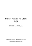
FOREWORD
This service manual is designed primarily for use by certified XINYANG Master Service Dealer
technicians in a properly equipped shop and should be kept available for reference. All references to
left and right side of the vehicle are from the operator's perspective when seated in a normal riding
position.
Some procedures outlined in this manual require a sound knowledge of mechanical theory, tool use,
and shop procedures in order to perform the work safely and correctly. Technicians should read the
text and be familiar with service procedures before starting the work. Certain procedures require the
use of special tools. Use only the proper tools as specified.
This manual contains an introductory description of procedures for inspection,maintenance,
overhaul , disassembly & assembly , removal and installation of components and parts,
troubleshooting and service data together with illustrations of our vehicle Model XY1100UE and
XY1100UEL.
The manufacturer reserves the right to make improvements or modifications to the products
without prior notice. Overhaul and maintenance should be done according to the actual state
and condition of the vehicle.
CONTENTS
Vehicle
Service Information
1
Vehicle Body, Muffler
Checks & Adjustment
Cooling System
Removal and Installation of Engine
Mechanical part of SQR 472Engine
Fuel injector system
Front Wheel, Front Brake, Suspension, Steering
Rear Wheel, Rear Brake, Suspension
Front and Rear Axle
EFI system of SQR 472engine
Lighting and switches
Relays and fuses distribution diagram
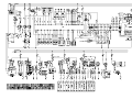
Circuit Diagram
2
3
4
5
6
7
8
9
10
11
12
1. SERVICE INFORMATION
A few Words About Safety ……………1-1
Main Data Table………………………1-20
Fasteners…………………………………1-3
Tightening Torque………………………1-24
Basic tools………………………………1-5
Lubricating oil, and brake liquid………1-25
Description and vehicle identification…1-18
VIN Number Engine Number…………1-19
A Few Words About Safety
Service Information
The service and repair information contained in this manual is intended for use by qualified,
professional technicians.
Attempting service or repairs without the proper training, tools, and equipment could cause injury to
you or others, It could also damage the vehicle or create an unsafe condition.
This manual describes the proper methods and procedures for performing service, maintenance, and
repairs. Some procedures require the use of specially designed tools and dedicated equipment. Any
person who intends to use a replacement part, service procedure or a tool that is not recommended
by XinYang, must determine the risks to their personal safety and the safe operation of the vehicle.
If you need to replace a part, use genuine XinYang parts with the correct part number or an
equivalent part. We strongly recommend that you do not use replacement parts of inferior quality.
For Your Customer is Safety
Proper service and maintenance are essential to the customer is safety and the reliability of the
vehicle. Any error or oversight while servicing a vehicle can result in faulty operation, damage to
the vehicle, or injury to others.
For Your Safety
Because this manual is intended for the professional service technician, we do not provide warnings
about many basic shop safety practices (e.g., Hot parts-wear gloves). If you have not received shop
safety training or do not feel confident about your knowledge of safe servicing practice, we
recommended that you do not attempt to perform the procedures described in this manual.
Some of the most important general service safety precautions are given below. However, we
cannot warn you of every conceivable hazard that can arise in performing service and repair and
procedures. Only you can decide whether or not you should perform a given task, can cause you to
be seriously hurt or killed.
Important Safety Precautions
Make sure you have a clear understanding of all basic shop safety practices and that you are
1-1
1
1. SERVICE INFORMATION
wearing appropriate clothing and using safety equipment. When performing any service task, be
especially careful of the following:
● Read all of the instructions before you begin, and make sure you have the tools, the replacement
or repair parts, and the skills required to perform the tasks safely and completely.
● Protect your eyes by using proper safety glasses, goggles or face shields any time you hammer,
drill, grind, pry or work around pressurized air or liquids, and springs or other stored-energy
components. If there is any doubt, put on eye protection.
● Use other protective wear when necessary, for example gloves or safety shoes. Handing hot or
sharp parts can cause severe burns or cuts. Before you grab something that looks like it can hurt
you, stop and put on gloves.
● Protect yourself and others whenever you have the vehicle up in the air. Any time you lift the
vehicle, either with a hoist or a jack, make sure that it is always securely supported. Use jack
stands.
Make sure the engine is off before you begin any servicing procedures, unless the instruction tells
you to do otherwise. This will help eliminate several potential hazards;
● Carbon monoxide poisoning from engine exhaust, Be sure there is adequate ventilation whenever
you run the engine.
● Burns from hot parts or coolant. Let the engine and exhaust system cool before working in those
areas.
● Injury from moving parts. If the instruction tells you to run the engine, be sure your hands, fingers
and clothing are out of the way.
Gasoline vapors and hydrogen gases from batteries are explosive. To reduce the possibility of a fire
or explosion, be careful when working around gasoline or batteries.
● Use only a nonflammable solvent, not gasoline, to clean parts.
● Never drain or store gasoline in an open container.
● Keep all cigarettes, sparks and flames away from the battery and all fuel-related parts.
Conversion Table
Item
Pressure
Example
2
200Kpa(2.00kgf/cm )
33kpa(250mmHg)
Conversion
2
1kgf/cm =98.0665kpa
1kpa=1000pa
1mmHg=133.322Pa=0.133322Kps
1kgf· m=9.80665N· m
Torque
18N· m(1.8kgf-m)
Volume
419ml
1ml=1 cm =1cc
3
1l=1000cm
Force
12N(1.2kgf)
1kgf=9.80665N
3
1-2
1. SERVICE INFORMATION
Cleaning Parts
Cleaning parts is one of the more tedious and difficult service jobs performed in the home garage.
Many types of chemical cleaners and solvents are available for shop use. Most are poisonous and
extremely flammable. To prevent chemical exposure, vapor buildup, fire and serious injury, observe
each product warning label and note the following:
1. Read and observe the entire product label before using any chemical. Always know what type of
chemical is being used and whether it is poisonous and/or flammable.
2. Do not use more than one type of cleaning solvent at a time. If mixing chemicals is required,
measure the proper amounts according to the manufacturer.
3. Work in a well-ventilated area.
4. Wear chemical-resistant gloves.
5. Wear safety glasses.
6. Wear a vapor respirator if the instructions call for it.
7. Wash hands and arms thoroughly after cleaning parts.
8. Keep chemical products away from children and pets.
9. Thoroughly clean all oil, grease and cleaner residue from any part that must be heated.
10. Use a nylon brush when cleaning parts. Metal brushes may cause a spark.
11. When using a parts washer, only use the solvent recommended by the manufacturer. Make sure
the parts washer is equipped with a metal lid that will lower in case of fire.
Warning Labels
Most manufacturers attach information and warning labels to the UTV. These labels contain
instructions that are important to personal safety when operating, servicing, transporting and storing
the UTV. Refer to the owner’s manual for the description and location of labels. Order replacement
labels from the manufacturer if they are missing or damaged.
FASTENERS
Proper fastener selection and installation is important to ensure the motorcycle operates as
designed and can be serviced efficiently. The choice of original equipment fasteners is not arrived at
by chance. Make sure replacement fasteners meet all the same requirements as the originals
Many screws. Bolts and studs are combined with nuts to secure particular components. to indicate
the size of a nut. Manufactures specify the internal diameter and the thread pitch
The measurement across two flats on a nut or bolt indicates the wrench size
WARNING
Warning : Do not install fasteners with a strength classification lower than what was originally
installed by the manufacturer doing so may cause equipment failure and or damage
Torque Specifications
The material used in the manufacturing of the UTV may be subjected to uneven stresses if the
fasteners of the various subassemblies are not installed and tightened correctly. Fasteners that are
improperly installed or work loose can cause extensive damage. it is essential to use an accurate
torque wrench as described in this chapter.
1-3
1
1. SERVICE INFORMATION
Self-Locking Fasteners
Several types of bolts. Screws and nuts incorporate a system that creates interference between
the two fasteners. Interference is achieved in various ways. The most common types are the nylon
insert nut and a dry adhesive coating on the threads of a blot.
Self-locking fasteners offer greater holding strength than standard fasteners, which improves their
resistance to vibration. All self-locking fasteners cannot be reused. The materials used to from the
lock become distorted after the initial installation and removal. Discard and replace self-locking
fasteners after removing them. Do not replace self-locking fasteners with standard fasteners.
Washers
The two basic types of washers are flat washers and lock washers. Flat washers are simple discs
with a hole to fit a screw or bolt. Lock washers are used to prevent a fastener from working loose.
Washers can be used as spacers and seals. Or can help distribute fastener load and prevent the
fastener from damaging the component
As with fasteners. When replacing washers make sure the replacement washers are of the same
design and quality
Cotter Pins
A cotter pin is a split metal pin inserted into a hole or slot to prevent a fastener from loosening. In
certain applications, such as the rear axle on an UTV or motorcycle, the fastener must be secured in
this way. For these applications. A cotter pin and castellated (slotted) nut is used.
To use a cotter pin, first make sure the diameter is correct for the hole in the fastener. Aster
correctly tightening the fastener and aligning the holes, insert the cotter pin through the hole and
bend the ends over the fastener, Unless instructed to do so, never loosen a tightened fastener to
align the holes. If the holes do not align. Tighten the fastener enough to achieve alignment
Cotter pins are available in various diameters and lengths. Measure the length from the bottom of
the head to the tip of the shortest pin.
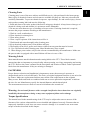
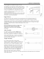
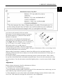
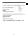
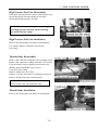
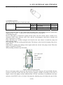
Snap Rings and E-clips
Snap rings (Figure 1) are circular-shaped metal
retaining clips. They secure parts in place on parts
such as shafts. External type snap rings are used to
retain items on shafts. Internal type snap rings secure
parts within housing bores. In some applications. in
addition to securing the component(s). snap rings of
varying thicknesses also determine endplay. These
are usually called selective snap rings.
The two basic types of snap rings are machined
and stamped snap rings. Machined snap rings (Figure
2) can be installed in either direction. Because both
faces have sharp edges. Stamped snap rings (Figure
3) are manufactured with a sharp and a round edge.
When installing a stamped snap ring in a thrust
1-4
1. SERVICE INFORMATION
application, install the sharp edge facing away from
the part producing the thrust.
E-clips are used when it is not practical to use a
snap ring. Remove E-clips with a flat blade
screwdriver by prying between the shaft and E-clip. To
install an E-clip. Center it over the shaft groove and
push or tap it into place
Observe the following when installing snap rings:
1. Remove and install snap rings with snap rings
pliers. Refer to Basic Tools in this chapter
2. In some applications. it may be necessary to
replace snap rings after removing them
3. Compress or expand snap rings only enough to
install them. If overly expanded. Lose their
retaining ability
4. After installing a snap ring. Make sure it seats completely
5. Wear eye protection when removing and installing snap rings
BASIC TOOLS
Most of the procedures in this manual can be carried out with basic hand tools and test equipment
familiar to the home mechanic. Always use the correct tools for the job. Keep tools organized and
clean. Store them in a tool chest with related tools organized together.
Quality tools are essential. The best are constructed of high-strength alloy steel. These tools are
light, easy to use and resistant to wear. Their working surface is devoid of sharp edges and carefully
polished. They have an easy-to-clean finish and are comfortable to use. Quality tools are a good
investment.
Some of the procedures in this manual specify special tools. In many cases the tools is illustrated
in use. Those with a large tool kit may be able to replacement. However, in some cases, the
specialized equipment or expertise may make it impractical for the home mechanic to attempt the
procedure. When necessary, such operations are recommended to have a dealership or specialist
perform the task. It may be less expensive to have a professional perform these jobs, especially
when considering the cost of equipment.
When purchasing tools to perform the procedures covered in this manual, consider the tool’s
potential frequency of use. If a tool kit is just now being started. Consider purchasing a basic tool
set from a quality tool combinations and offer substantial savings when complicated, specialized
tools can be added.
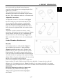
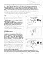
Screwdrivers
Screwdrivers of various lengths and types are mandatory for the simplest tool kit. The two basic
types are the slotted tip (flat blade) and the Phillips tip. These are available in sets that often include an
assortment of tip size and shaft lengths.
As with all tools, use a screwdriver designed for the job. Make sure the size of the fastener. Use
them only for driving screws. Never use a screwdriver for
prying or chiseling metal. Repair or replace worn or
1-5
1
1. SERVICE INFORMATION
damaged screwdrivers. A worn tip may damage the
fastener, making it difficult to remove.
Phillips-head screws are often damaged by
incorrectly fitting screwdrivers. Quality Phillips
screwdrivers are manufactured with their crosshead tip
machined to Phillips Screw Company specifications.
Poor quality or damaged Phillips screwdrivers can back
out (cam out) and round over the screw head. In addition.
Weak or soft screw materials can make removal difficult.
The best type of screwdriver to use on Phillips
screw is the ACR Phillips II screwdriver, patented by the
horizontal anti-cam out ribs found on the driving faces or
flutes of the screwdriver’s tip (figure 4). ACR Phillips II
screwdrivers were designed as part of a manufacturing
drive system to be used with ACR Phillips II screws, but
they work of tool companies offer ACR Phillips II
screwdrivers in different Tip size and interchangeable
bits to fit screwdriver bit holders.
NOTE:
Another way to prevent cam out and to increase
the grip of a Phillips screwdriver is to apply valve
grinding compound or permute screw & socket
Gripper onto the screwdriver tip. After loosening/
tightening the screw, clean the screw recess to
prevent engine oil contamination.
Wrenches
Open-end, box-end and combination wrenches
(figure 5) are available in a variety of types and sizes.
The number stamped on the wrench refers to the distance
of the fastener head.
The box-end wrench is an excellent tool because it grips
the fastener on all sides. This reduces the chance of the
tool slipping. The box-end wrench is designed with either
a 6 or 12-point opening. For stubborn or damaged fasteners,
the 6-point provides superior holding because it contacts the
fastener across a wider area at all six edges. For general use,
the 12-point works well. It allows the wrench to be removed
and reinstalled without moving the handle over such a wide
are.
An open-end wrench is fast and works best in
areas with limited overhead access. It contacts the
fastener at only two points and is subject to slipping if
under heavy force, or if the tool or fastener is worn. A
1-6
1. SERVICE INFORMATION
box-end wrench is preferred in most instances,
especially when braking loose and applying the final
tightness to a fastener.
The combination wrench has a box-end on one
end and an open-end on one end and an open-end on
the other. This combination makes it a convenient tool.
Adjustable wrenches
An adjustable wrench or Crescent wrench (Figure
6) can fit nearly any nut or bolt head that has clear
access around its entire perimeter. An adjustable
wrench is best used as a backup wrench to keep a
large nut or bolt from turning while the other end is
being loosened or tightened with a box-end or socket
wrench.
Adjustable wrenches contact the fastener at only
two points, which makes them more subject to slipping
off the fastener. Because one jaw is adjustable and
may become loose, this shortcoming is aggravated.
Make certain the solid jaw is the one transmitting the
force.
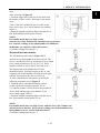
Socket Wrenches, Ratchets and
Handles
Sockets that attach to a ratchet handle (Figure 7)
are available with 6-point or 12-point openings
(Figure8) and different drive sizes. The drive size
Indicates the size of the square hole that accepts the
Ratchet handle. The number stamped on the socket
is the size of the work area and must the fastener head
As with wrenches. a 6-point provides superior-holding
ability. While a 12-point socket needs to be moved only
half as for to reposition it on the fastener
Sockets are designated for either hand or impact use.
Impact sockets are made of thicker material for more durability. Compare the size and wall
thickness of a 19-mmhand socket (A, Figure 9) and the 19-mm impact socket (B). Use impact
sockets when using an impact driver or air tools. Use hand sockets with hand-driven attachments
WARNING:
Do not use hand sockets with air or impact tools
because they may shatter and cause injury.
Always wear eye protection when using impact
or air tools
1-7
1
1. SERVICE INFORMATION
Various handles are available for sockets. Use the
speed handle for fast operation. Flexible ratchet heads in
varying length allow the socket to be turned with varying
force and at odd angles. Extension bars allow the socket
setup to reach difficult areas. The ratchet is the most
versatile. It allows the user to install or remove the nut
without removing the socket.
Sockets combined with any number of drivers make them
undoubtedly the fastest. Safest and most convenient tool
for fastener removal and installation
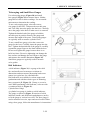
Impact Drivers
An impact driver provides extra force for removing fasteners by converting the impact of a
hammer into a turning motion. This makes it possible to remove stubborn fasteners without
damaging them. Impact drivers and interchangeable bits (Figure 10) are available from most tool
suppliers.When using a socket with an impact driver. Make sure the socket is designed for impact
use. Refer to Socket Wrenches. Ratchets and handles in this section.
WARNING:
Do not use hand sockets with air or impact tools
because they may shatter and cause injury.
Always wear eye protection when using impact
or air tools
Allen Wrenches
Use Allen or setscrew wrenches (Figure 11) on
fasteners with hexagonal recesses in the fastener
head. These wrenches are available in L-shaped bar.
Socket and T-handle types. A metric set is required
when working on most motorcycles. Allen bolts are
sometimes called socket bolts.
Torque Wrenches
Use a torque wrench with a socket, torque
adapter or similar extension to tighten a fastener to a
measured torque. Torque wrenches come in several
drive sizes (1/4, 3/8, 1/2 and 3/4) and have various
methods of reading the torque value. The drive size
indicates the size of the square drive that accepts the
socket, adapter or extension. Common methods of
reading the torque value are the deflecting beam, the
dial indicator and the audible click (Figure 12).
When choosing a torque wrench, consider the
torque range, drive size and accuracy. The torque specifications in this manual provide an indication
of the range required.
1-8
1. SERVICE INFORMATION
A torque wrench is a precision tool that must be properly cared for to remain accurate. Store
torque wrenches in cases or separate padded drawers within a toolbox. Follow the manufacturer’s
instructions for their care and calibration.
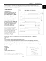
Torque Adapters
Torque adapters or
extensions extend or reduce the
reach of a torque wrench. The
torque adapter shown in (Figure
13) is used to tighten a fastener
that cannot be reached because
of the size of the torque wrench
head, drive, and socket. If a
torque adapter changes the
effective lever length (Figure 14),
the torque reading on the wrench
will not equal the actual torque
applied to the fastener. It is
necessary to recalibrate the
torque setting on the wrench to
compensate for the change of
lever length. When using a torque
adapter at a right angle to the
drive head, calibration is not
required, because the effective
length has not changed.
To recalculate a torque
reading when using a torque adapter, use the following formula and refer to Figure 14:
TW = TA×L
L+A
TW is the torque setting or dial reading on the wrench.
TA is the torque specification and the actual amount of torque that is applied to the fastener.
A is the amount that the adapter increases (or in some cases reduces) the effective lever length as
measured along the centerline of the torque wrench.
L is the lever length of the wrench as measured from the center of the drive to the center of the grip.
The effective length is the sum of L and A.
Example:
TA=20 ft.-lb.
A=3in.
L=14in.
TW=20×14=280=16.5 ft. - lb.
14+3 = 17
In this example, the torque wrench would be set
to the recalculated torque value (TW = 16.5 ft. –lb.).
1-9
1
1. SERVICE INFORMATION
When using a beam-type wrench, tighten the fastener
until the pointer aligns with 16.5 ft. –lb. In this example,
although the torque wrench is pre set to 16.5 ft. –lb.,
the actual torque is 20 ft. –lb.
Pliers
Pliers come in a wide range of types and sizes.
Pliers are useful for holding, cutting, bending, and
crimping. Do not use them to turn fasteners. Figure 15
and Figure 16 show several types of useful pliers.
Each design has a specialized function. Slip-joint
pliers are general – purpose pliers used for gripping
and bending. Diagonal cutting pliers are needed to cut
wire and can be used to remove cotter pins. Use
needle nose pliers to hold or bend small objects.
Locking pliers (Figure 16), sometimes called ViseGrips, are used to hold objects very tightly. They have
many uses ranging from holding two parts together, to
gripping the end of a broken stud. Use caution when
using locking pliers, as the sharp jaws will damage the
objects they hold.
Snap Ring Pliers
Snap ring pliers are specialized pliers with tips that
fit into the ends of snap rings to remove and install them.
Snap ring pliers (Figure 17) are available with a fixed action (either internal or external ) or
convertible (one tool works on both internal and external snap rings). They may have fixed tips or
interchangeable ones of various sizes and angles. For general use, select a convertible type pliers
with interchangeable tips (Figure 17).
WARNING:
Snap rings can slip and fly off when removing and
installing them. Also, the snap ring pliers tips may break.
Always wear eye protection when using snap ring pliers.
Hammers
Various types of hammers are available to fit a number of applications. Use a ball-peen hammer to
strike another tool, such as a punch or chisel. Use soft-faced hammers when a metal object must be
struck without damaging it. Never use a metal-faced hammer on engine and suspension components
because damage occurs in most cases.
Always wear eye protection when using hammers. Make sure the hammer face is in good
condition and the handle is not cracked. Select the correct hammer for the job and make sure to
strike the object squarely. Do not use the handle or the side of the hammer to strike an object.
1-10
1. SERVICE INFORMATION
Ignition Grounding Tool
Some test procedures require turning the engine
over without starting it. To prevent damage to the
ignition system from excessive resistance or the
possibility of fuel vapor being ignited by an open spark,
remove the spark plug cap and ground it directly to a
good engine ground with the tool shown in (Figure
18).
Make the tool shown from a No.6 screw and nut,
two washers, length of tubing, alligator clip, electrical eyelet and a length of wire.
PRECISION MEASURING TOOLS
The ability to accurately measure components is essential to perform many of the procedures
described in this manual. Equipment is manufactured to close tolerances, and obtaining consistently
accurate measurements is essential to determine which components require replacement or further
service.
Each type of measuring instrument is designed to measure a dimension with a certain degree of
accuracy and within a certain range. When selecting the measuring tool, make sure it is applicable
to
the task.
As with all tools, measuring tools provide the best results if cared for properly. Improper use can
damage the tool and cause inaccurate results. If any measurement is questionable, verify the
measurement using another tool. A standard gauge is usually provided with micrometers to check
accuracy and calibrate the tool if necessary.
Precision measurements can vary according to the experience of the person performing the
procedure. Accurate results are only possible if the mechanic possesses a feel for using the tool.
Heavy-handed use of measuring tools produces less accurate results. Hold the tool gently by the
fingertips to easily feel the point at which the tool contacts the object. This feel for the equipment
produces more accurate measurements and reduces the risk of damaging the tool or component.
Refer to the following sections for specific measuring tools.
Feeler Gauge
Use feeler or thickness gauges (Figure19) for
measuring the distance between two surfaces.
A feeler gauge set consists of an assortment of
steel strips of graduated thickness. Each blade is
marked with its thickness. Blades can be of various
lengths and angles for different procedures.
A common use for a feeler gauge is to measure
valve clearance. Use wire (round) type gauges to
measure spark plug gap.
1-11
1
1. SERVICE INFORMATION
Calipers
Calipers (Figure 20) are excellent tools for
obtaining inside, outside and depth measurements.
Although not as precise as a micrometer, they allow
reasonable precision, typically to within 0.05 mm
(0.001 in.). Most calipers have a range up to 150 mm
(6 in.).
Calipers are available in dial, venire or digital versions. Dial calipers have a dial readout that
provides convenient reading. Venire calipers have marked scales that must be compared to
determine
the measurement. The digital caliper uses a liquid-crystal display (LCD) to show the measurement.
Properly maintain the measuring surfaces of the caliper. There must not be any dirt or burrs
between the tool and the object being measured. Never force the caliper to close around an object.
Close the caliper around the highest point so it can be removed with a slight drag. Some calipers
require calibration. Always refer to the manufacturer’s instructions when using a new or unfamiliar
caliper.
To read a vernire. Calipers refer to Figure 21. The
fixed scale is marked in l-mm increments. Ten
individual lines on the fixed scale equal 1 cm. The
movable scale is marked in 0.05 mm (hundredth)
increments. To obtain a reading, establish the first
number by the location of the 0 line on the movable
scale in relation to the first line to the left on the fixed
scale. In this example, the number is 10 mm. To
determine the next number, note which of the lines on
the movable scale align with a mark on the fixed scale.
A number of lines will seem close, but only one will align exactly. In this case, 0.50 mm is the
reading to
add to the first number. Adding 10 mm and 0.50 mm equals a measurement of 10.50 mm.
Micrometers
A micrometer is an instrument designed for linear measurement using the decimal divisions of
the inch or meter (Figure 22). While there are many types and styles of micrometers, most of the
1-12
1. SERVICE INFORMATION
1
procedures in this manual call for an outside
micrometer. Use the outside micrometer to measure
the outside diameter of cylindrical forms and the
thickness of materials.
A micrometer’s size indicates the minimum and
maximum size of a part that it can measure. The usual
sizes (Figure 23) are 0-25mm (0-1 in.), 25-50 mm (1-2
in.), 50-75 mm (2-3 in.) and 75-100 mm (3-4 in.).
Micrometers that cover a wider range of
measurements are available. These use a large frame
with interchangeable anvils of various lengths. This type of micrometer offers a cost savings, but its
overall size may make it less convenient.
When reading a micrometer, numbers are taken from different scales and added together. The
following sections describe how to adjust, care for and read the measurements of various types of
outside micrometers.
For accurate results, properly maintain the measuring surfaces of the micrometer. There cannot
be any dirt or burrs between the tool and the measured object. Never force the micrometer to close
around an object. Close the micrometer around the highest point so it can be removed with a slight
drag.
Adjustment
Before using a micrometer, check its adjustment as follows:
1. Clean the anvil and spindle faces.
2A. To check a 0-1 in. or 0-25 mm micrometer:
a. Turn the thimble until the spindle contacts the anvil. If the micrometer has a ratchet stop, use it to
ensure that the proper amount of pressure is applied.
b. If the adjustment is correct, the 0 mark on the thimble will align exactly with the 0 mark on the
sleeve line. If the marks do not align, the micrometer is out of adjustment.
1-13
1. SERVICE INFORMATION
c. Follow the manufacturer’s instructions to adjust the micrometer.
2B. To check a micrometer larger than 1 in. or 25 mm use the standard gauge supplied by the
manufacturer. A standard gauge is a steel block, disc or rod that is machined to an exact size.
a. Place the standard gauge between the spindle and anvil, and measure its outside diameter or
length. If the micrometer has a ratchet stop, use it to ensure that the proper amount of pressure is
applied.
b. If the adjustment is correct, the 0 mark on the thimble will align exactly with the 0 mark on the
sleeve line. If the marks do not align, the micrometer is out of adjustment.
c. Follow the manufacturer’s instructions to adjust the micrometer.
Care
Micrometers are precision instruments. They must
be used and maintained with great care. Note the
following:
1. Store micrometers in protective cases or separate
padded drawers in a tool box.
2. When in storage, make sure the spindle and anvil
faces do not contact each other or another object. If
they do, temperature changes and corrosion may
damage the contact faces.
3. Do not clean a micrometer with compressed air. Dirt
forced into the tool will cause wear.
4. Lubricate micrometers with WD-40 to prevent
corrosion.
Metric micrometer
The standard metric micrometer (Figure 24) is
accurate to one one-hundredth of a millimeter (0.01
mm). The sleeve line is graduated in millimeter and
half millimeter increments. The marks on the upper
half of the sleeve line equal 1.00 mm. Each fifth mark
above the sleeve line is identified with a number. The
number sequence depends on the size of the
micrometer. A 0-25 mm micrometer, for example, will
have sleeve marks numbered 0 through 25 in 5 mm
increments. This numbering sequence continues with
larger micrometers. On all metric micrometers, each
mark on the lower half of the sleeve equals 0.50mm.
The tapered end of the thimble has 50 lines marked
around it. Each mark equals 0.01 mm. One completer
turn of the thimble aligns its 0 mark with the first line
lower half of the sleeve line or 0.50mm.
When reading a metric micrometer, add the number of millimeters and half-millimeters on the
sleeve line to the number of one one-hundredth millimeters on the thimble. Perform the following
1-14
1. SERVICE INFORMATION
steps
while referring to Figure 25.
1. Read the upper half of the sleeve line and count
the number of lines visible. Each upper line equals
1mm.
2. See if the half –millimeter line is visible on the
lower sleeve line. If so, add 0.50mm to the reading
in Step 1.
3. Read the thimble mark that aligns with the sleeve
line. Each thimble mark equals 0.01mm.
NOTE:
If a thimble mark does not align exactly
with the sleeve line. Estimate the amount between the lines.
For accurate readings in two-thousandths of a millimeter
(0.002mm), use a metric vernier micrometer.
4. Add the readings from Steps 1-3.
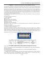
Standard inch micrometer
The standard inch micrometer (Figure 26) is
accurate to one-thousandth of an inch or 0.001. The
sleeve is marked in 0.025 in. increments. Every fourth
sleeve mark is numbered 1,2,3,4,5,6,7,8,9. These
numbers indicate 0.100, 0.200, 0.300, and so on.
The tapered end of the thimble has 25 lines
marked around it. Each mark equals 0.001 in. One
complete turn of the thimble will align its zero mark
with the first mark on the sleeve or 0.025 in.
To read a standard inch micrometer, perform the
following steps and refer to Figure 27.
1. Read the sleeve and find the largest number
visible. Each sleeve number equals 0.100 in.
2. Count the number of lines between the numbered
sleeve mark and the edge of the thimble. Each
sleeve mark equals 0.025 in.
3. Read the thimble mark that aligns with the sleeve
line. Each thimble mark equals 0.01 in.
NOTE:
If a thimble mark does not align exactly with the sleeve line, estimate the
amount between the lines. For accurate readings in ten-thousandths of an
inch (0.0001 in), use a vernier inch micrometer.
4. Add the readings from Steps 1-3.
1-15
1
1. SERVICE INFORMATION
Telescoping and Small Bore Gauges
Use telescoping gauges (Figure 28) and small
bore gauges (Figure 29) to measure bores. Neither
gauge has a scale for direct readings. Use an outside
micrometer to determine the reading.
To use a telescoping gauge, select the correct
size gauge for the bore. Compress the movable post
and. Care fully insert the gauge into the bore. Carefully
move the gauge in the bore to make sure it is centered.
Tighten the knurled end of the gauge to hold the
movable post in position. Remove the gauge and
measure the length of the posts. Telescoping gauges
are typically used to measure cylinder bores.
To use a small bore gauge, select the correct size
gauge for the bore. Carefully insert the gauge into the
bore. Tighten the knurled end of the gauge to carefully
expand the gauge fingers to the limit within the bore.
Do not over tighten the gauge because there is no
built-in release. Excessive tightening can damage the
bore surface and damage the tool. Remove the gauge
and measure the outside dimension (Figure 30).
Small bore gauges are typically used to measure
valve guides.
Dial Indicator:
A dial indicator (Figure 31) is a gauge with a dial
face and needle used to measure variations in
dimensions and movements. Measuring brake rotor
runout is a typical use for a dial indicator.
Dial indicators are available in various ranges and
graduations and with three basic types of mounting
bases: magnetic (B. Figure 31). Clamp, or screw-in
stud. When purchasing a dial indicator, select on with
a continuous dial (A, Figure 31).
Cylinder Bore Gauge
A cylinder bore gauge is similar to a dial indicator.
The gauge set shown in Figure 32 consists of a dial
indicator, handle, and different length adapters (anvils)
to fit the gauge to various bore sizes. The bore gauge is
used to measure bore size, taper and out-of-round. When
using a bore gauge, follow the manufacturer’s instructions.
1-16
1. SERVICE INFORMATION
Compression Gauge
A compression gauge (Figure 33) measures combustion chamber (cylinder) pressure, usually in
PSI or kg/ cm2 . The gauge adapter is either inserted or screwed into the spark plug hole to obtain
the
reading. Disable the engine so it does not start and
hold the throttle in the wide-open position when
performing a compression test An engine that does
not have adequate compression cannot be properly
tuned. Refer to Chapter Three.
Multimeter
A multimeter (Figure 34) is an essential tool for
electrical system diagnosis. The voltage function
indicates the voltage applied or available to various electrical components. The ohmmeter function
tests circuits for continuity, or lack of continuity, and measures the resistance of a circuit.
Some manufacturer’s specifications for electrical components are based on results using a specific
test meter. Results may vary if using a meter not recommended by the manufacturer. Such
requirements are noted when applicable.
Ohmmeter (analog) calibration
Each time an analog ohmmeter is used or if the scale is changed, the ohmmeter must be
calibrated.
Digital ohmmeters do not require calibration.
1. Make sure the meter battery is in good condition.
2. Make sure the meter probes are in good condition.
3. Touch the two probes together and observe the needle location on the ohms scale. The needle
must Align with the 0 mark to obtain accurate measurements.
4. If necessary, rotate the meter ohms adjust knob until the needle and 0 mark align.
1-17
1
1. SERVICE INFORMATION
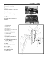
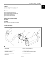
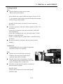
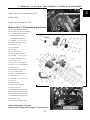
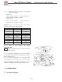
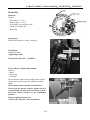
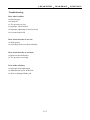
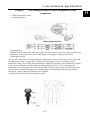
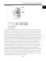
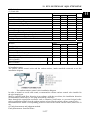
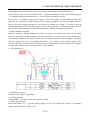
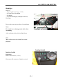
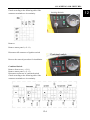
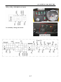
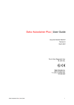
Description and vehicle identification
1. Meter adjust button
2. Driver model turn switch
3. Turning switch
4. Light switch
5. Low beams/High beams turn
6. Horn switch
7. Gear Selector
8. Ignition Switch
9. Meter
10. Warning indicator light switch
11. Wiper switch(optional)
12. Spot light(optional)
13. Cigarette lighter
14. winch switch(optional)
15. Auxiliary DC jack(12V 120W/10A)
1-18
1. SERVICE INFORMATION
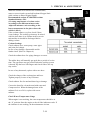
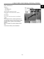
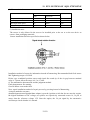
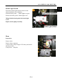
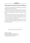
Identification number records
Record the vehicle identification number and engine number in the spaces provided for assistance
when ordering spare parts from your dealer or for reference in case the vehicle is stolen.
Vehicle Identification Number(1100UE): LCXRSAS3~
Vehicle Identification Number(1100UEL): LCXLSAS3~
Engine Number: SQR472F
NOTE: The vehicle identification number is used to identify your
machine.
1-19
1
1. SERVICE INFORMATION
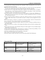
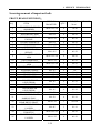
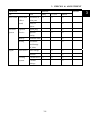
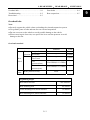
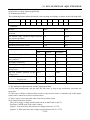
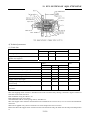
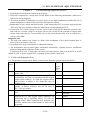
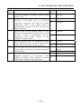
Main Data Table
Item
Parameter
Model
Length
Width
Height
Wheel base
Engine type
Displacement
Fuel type
1100UE/1100UEL
2830mm/3630mm
1640mm/1640 mm
2130mm/2130mm
1830mm/2630mm
SQR472F
1083ml
Unleaded gasoline 93octane or above
Mass of whole equipments (Not include driver)
Number of Passengers
Max. Load
Tire
711kg/800 kg
2 for 1100UE, 4 for 1100UEL(including driver)
300Kg
26x9-14
26x11-14
Front
Rear
Minimum turning radius
4500mm/5000mm
Start-up mode
Electric starter
Type
in-line Vertical, four-cylinder, water-cooled,
DOHC
Combustion Chamber Type
Tent-shaped
Bore × stroke
72×66.5 mm (2.83×2.62 in)
Compression ratio
9.5:1
Lubrication Type
Compound (pressure, splash lubrication)
Cool type
Mandatory cycle of antifreeze-coolant
Maximal power.
50Kw/6000 rpm(EEC model less than
15kw)
90N.M/3500~4000 rpm(EEC
model:45N.M/2240 rpm)
≤ 275g/Kw·h
Max. torque
Engine
Lowest fuel consuming rate (g/Kw·h)
Idling speed (r/min)
850±50 r/min
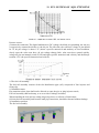
Starting Performance
The engine should be started smoothly in 30S
without any special measure when the air
temperature is -25℃.Start test is allowed to start
three times continuously as a row. It can be
restarted in 2 minutes later after the first failure.
The direction of camshaft rotary motion
clockwise(From the front-end look at the
engine crankshaft pulley)
Spark plug
K6RTG
Generators
14V75A whole-alternator
Lubricating oil category
Engine oil pump type
Oil filter type
API SF SAE 10W/30
Fuel supply
EFI
Rotor Style
As a whole mounted rotating
1-20
1. SERVICE INFORMATION
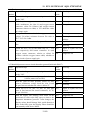
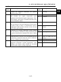
Parameter
Item
Fuel type
Transmission
Engine/
Gearing
Steering
device
V-belt with teeth on, auto stepless gear
change, plus gear change cam with change
gear transmission
gear lever with hand
wet, hoof centrifugal type
(stepless speed 0.84—3.28
Gear change type
Clutch type
Primary speed change ratio
change)
Speed change ratio:
H Gear:2.66
L Gear: 5.527
R Gear: 6.80
Cooling style
Cooling fluid type
Out dimension
Net weight
Output type
Shaft running direction
Steering
Right
angle
Left
Brake type
Bumper
Device
Frame type
93 unleaded gasoline high cleanliness
Total speed reduce ratio
2.23—8.72
4.64—18.13
5.71—22.30
Closed cooling fluid circulating
antifreeze with prevent rust
555.8 x 455.9 x 699
80kg
front and rear shaft output
counter-clockwise (from back of engine).
40°
Front
40°
Hydraulic Disc
Rear
Hydraulic Disc
Suspension
Swing Arm
Welded steel tube and plate
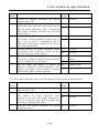
Overhaul Datasheet
Lubricating device
Item
Oil pump
Rotor
Engine Oil
Capacity
Standard
0.05~0.18mm
Gap between inner
and outer rotors
Gap between rotor and 0.10~0.181mm
body
Volume when replacing
3500ml
Full capacity
3600ml
1-21
Service limit
0.35mm
0.25mm
—
—
1
1. SERVICE INFORMATION
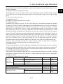
Recommended Oil (see original)
● Specially for 4-stroke
motorcycle
SAE-10W-40、20W-50
Substitutes must be used in
the following range.
●API type: SE or SF grade
●SAE type: Choose from
the left chart according to
the
environmental
temperature
Cooling Device
Item
Standard
Coolant
capacity
Full Capacity
4500ml
Reservoir tank capacity
3300 ml
Standard Density
50%
Opening pressure of radiator cap
Thermostat
108kpa(1.1kgf/cm2)
Temperature / valve open
72±2 ºC
Temperature/valve full open
88 ºC
Overall lift
3.5-4.5mm/95ºC
Front/Rear Wheel
Item
Front
Wheel
Rear
Wheel
Standard
1.0mm
Service Limit
2.0mm
1.0mm
2.0mm
—
12PSI(83KPa)
3.0mm
±0.5PSI(±3.5KPa)
Play of wheel Vertical
rim
Horizontal
1.0mm
2.0mm
1.0mm
2.0mm
Tire
Groove
—
3.0mm
Pressure
12PSI(83KPa)
±0.5PSI(±3.5KPa)
Play of wheel Vertical
rim
Horizontal
Tire
Groove
Pressure
Brake System
Item
Front brake
Rear brake
Standard
Brake Pedal Play
0mm
Brake disc thickness 4mm
Brake Pedal Play
0mm
Service Limit
-3mm
--
Brake disc thickness
4mm
3mm
1-22
1. SERVICE INFORMATION
Battery、Charging System
Item
AC magneto
Motor
Standard
Permanent magnet AC type
Model
Output
3- phase AC
Charging coil Resistance (20℃)
Rectifier
Battery
0.2-0.3Ω
Three-phase annular rectification, Silicon controlled
parallel-connected regulated voltage
Capacity
12V36Ah
Terminal point
voltage
Charging
current/time
Fully charged
12.8V
Insufficient
charge
Standard
<11.8V
0.9A/5~10H
Quick
4A/1H
Ignition system
Item
Ignition
Spark Plug
Standard
Type
ECU ignition
K6RTG (NGK)
Optional
---
Spark plug gap
0.9-1.1mm
1-23
1
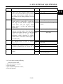
1. SERVICE INFORMATION
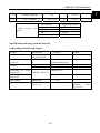
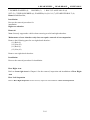
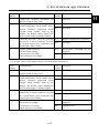
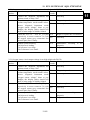
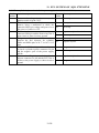
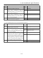
Screwing moment of important bolts
FRONT, REAR SUSPENSION:
S.Q.
1
2
3
4
5
6
7
8
9
10
11
12
13
14
15
16
17
18
19
20
21
22
23
24
25
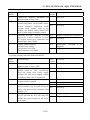
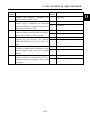
ITEM
FRONT/REAR SHOCK
ABSORBER
FRONT BRAKE DISK
REAR BRAKE DISK
RUBBER WASHER OF
ENGINE
ENGINE SUPPORT A
ENGINE SUPPORT B
CVT DRIVER
CVT SECONDARY
SHEAVE
FRONT LOWER/ UPPER
ARM
JOINT,ARM BALL
REAR LOWER/ UPPER
ARM
FRONT/REAR AXLE NUT
STEERING WHEEL
STEERING SHAFT
FRONT AXLE
FRONT AXLE
HOLDER,FRONT
AXLE(FR/RR)
REAR AXLE
HOLDER,REAR
AXLE(FR/RR)
FRONT DRIVE SHAFT
REAR DRIVE SHAFT/
PARKING DISC
COUPLING FLANGE,
REAR DRIVE SHAFT
SUPPORT,PARKING
CALIPER
HOLDER,BRAKE AND
THROTTLE
FRONT/REAR BRAKE
CALIPER
THREAD
DIAMETER
QTY.
TORQUE
(N·m)
M10×1.25×50
8
30~40
M10×25
M10×25
8
8
40~50
40~50
M10×1.25
8
40~50
M10×25
M10×1.25
M12×175
4
2
1
40~50
40~50
40~50
M10×115
1
40~50
M10×1.25×90
8
40~50
M10×1.25
2
40~50
M10×1.25×90
8
40~50
M18
M5×15
M8×25
M10×1.25×145
M10×1.25×85
4
6
4
1
1
180~200
10
20~30
40~50
40~50
M8×16
6
20~30
M12×1.25×115
2
40~50
M8×16
6
20~30
M8×25
4
20~30
M8×30
4
20~30
M14×1.25
1
90~100
M8×45
3
20~30
M10×1.25×25
4
40~50
M10×1.25
8
40~50
1-24
REMARK
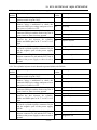
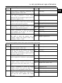
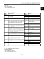
1. SERVICE INFORMATION
26
HANDLE BRAKE
M8
3
20~30
27
NUT , WHEEL
M12×1.25
16
40~50
Other
grade)
screws ( 8.8
Specification
M6
M8
M10
M12
Tightening moment
10N·m
25N·m
50N·m
80N·m
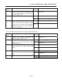
Specification and usage quantity for fuel
Lubricating oil and brake liquid
Category
Fuel
Specification
Capacity
RQ-93or upper grade
35L
lead-free gasoline
Lubricating oil(engine, SAE15W—40/SF or 3600ml(change oil)
Gear box)
SC
3500ml(change filter)
Front :500ml
Gearbox
Rear :1300ml
Lubricating oil ( front
Change 0.25L
SAE80W—90/GL-4
main driver)
Lubricating oil ( Rear
Change 0.18L
main driver)
Brake liquid
GB1083 JG3
0.5L
Engine coolant
Distilled
water:
Glycol =1:1
1-25
Remark
Extremely cold area,
Distilled
water:
Glycol =2:3
1
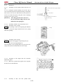
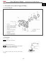
2. Vehicle body,Muffler
Overhaul info……………………………2-1
Troubleshooting…………………………2-1
Steering wheel & platfond ………………2-2
Windshield assembly………………………2-3
Side door…………………………………2-4
Triangular cover & rear board……………2-5
Seat belt & main protect pole assy…………2-6
Front bumper………………………………2-9
Front line cover & front air guide cover assy…2-10
Front cover assy……………………………2-11
Cargo box…………………………………2-13
Muffler……………………………………2-16
Overhaul Information
Operation Cautions
Warning
Gasoline is highly flammable, therefore smoke and fire are strictly forbidden in the work
place. Special attention should also be paid to sparks. Gasoline may also be explosive
when it is vaporized, so operation should be done in a well-ventilated place.
Remove and Install muffler after it is fully cold.
● This chapter is on the disassembly and installation of rack, visible parts, exhaust pipe,
Muffler and fuel tank.
● Hoses, cables and wiring should be routed properly
● Replace the gasket with a new one after muffler is removed
● After muffler is installed, check if there is any exhaust leakage.
Tightening torque
Muffler Exhaust Pipe Nut: 40-50N.m
Troubleshooting
Loud exhaust noise
● Broken muffler
● Exhaust leakage
Insufficient power
● Distorted muffler
● Exhaust leakage
● Muffler clogged
2-1
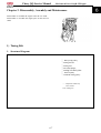
2. Vehicle body,Muffler
2
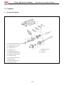
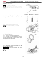
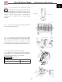
Cover, steering wheel
Remove
Exert upward to separate cover, steering
Wheel.
Installation
Reverse the removal procedure for
Installation
Steering wheel
Remove
Remove six bolts 1
Remove steering wheel
Installation
Note
Align the front wheel first, and then
adjust steering wheel;
Reverse the removal procedure for
Installation
Platfond
Remove
Remove four bolts 2
Remove platfond
Installation
Reverse the removal procedure for
Installation
2-2
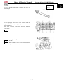
2. Vehicle body,Muffler
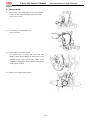
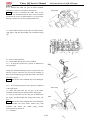
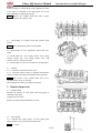
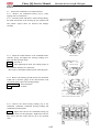
Windshield Assembly
Remove
Separate the connector of wiper motor.
Remove four bolts 1.
Remove windshield assembly.
Installation
Reverse the removal procedure for
Installation
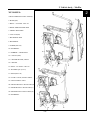
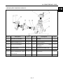
1. WIPER BLADE
2. WIPER ARM
3. BOLT(M6×20)
4. WINDSHIELD SCALEBOARD
5. BOLT(M6×16)
6. FARDAGE WINDSHIELD
7. CAP NUT (M6)
8. HOOP (Φ45)
9. WINDSHIELD IMMOBILITY
PLANK(TOP)
10. WINDSHIELD IMMOBILITY
PLANK(BELOW)
11. NUT,FLANGE(M6)
12. WIPER
13. DUST COVER, RUBBER
14. NUT (M12)
15. WASHER (Φ12)
16. RUBBER WASHER
17. WIPER ASSY
2-3
2. Vehicle body,Muffler
2
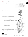
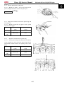
Side door (LF)
Remove
Remove bolt 1
Remove side door (LF)
Remove the side door of the another side in
the above way.
Installation
Reverse the removal procedure for
Installation.
1100UEL:Side door (LR)
Remove
Remove bolt 2
Remove side door (LR)
Remove the side door of the another side in
the above way.
Installation
Reverse the removal procedure for
installation
15. TAPPING SCREW (ST 4.2×20)
16. SCREW (M6×25)
17. HANDLE, HALF DOOR (L)
18. SCREW (M5×20)
19. INNER HALF DOOR (L)
20. INNER HALF DOOR (R)
21. WASHER (Φ5×Φ10×1)
22. BOLT FLANGE (M6)
23. BOLT FLANGE (M6×16)
24. BOLT FLANGE (M5)
25. CABLE, HALF DOOR
26. HANDLE, HALF DOOR(R)
27. OUTER HALF DOOR (L)
28. OUTER HALF DOOR (R)
2-4
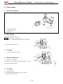
2. Vehicle body,Muffler
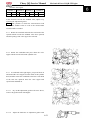
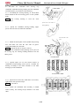
Triangular Cover
Remove
Remove bolt 1
Remove triangular cover
Remove the triangular cover of the another side in
the above way.
Installation
Reverse the removal procedure for installation.
Rear Left Board
Remove
Remove bolt 2
Remove bolt 3
Remove rear left board.
Remove the rear right board in the above way.
Installation
Reverse the removal procedure for Installation.
2-5
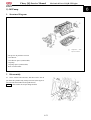
2. Vehicle body,Muffler
2
Seat belt
Remove
Remove bolt 3
Remove bolt 4
Remove driver seat belt.
Remove the passenger seat belt in the above way.
Remove rear seat belt of passenger in same method.
Installation
Reverse the removal procedure for Installation.
Install rear seat belt of passenger in same method.
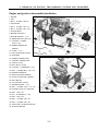
Main Protect Pole ASSY
Remove
Remove bolt 1
Remove bolt 2
Remove the main protect pole assy of the another
side in the above way.
Remove main protect pole assy.
Installation
Reverse the removal procedure for Installation.
2-6
2. Vehicle body,Muffler
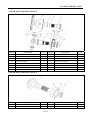
XY1100UE:
1. FRONT PROTECT POLE ASSY (L)
2. HOOP (Ф45)
3. BOLT,FLANGE(M8×16)
4. REAR THWARTWISE PIPE
5. FRONT BENT PIPE
6. CAP NUT (M8)
7. BACKREST PIPE
8. HEADREST
9. SCREW (M5×20)
10. BACKREST
11. RUBBER,STORE BOX
12. CAP NUT(M6)
13. CENTER SPACER, HOOP
14. PLATFOND
15. BOLT,FLANGE(M6×55)
16. WASHER(Ф6×Ф12×2)
17. BOLT (M10×30)
18. LOCK CATCH, SAFETY BELT
19. SAFETY BELT ASSY
20. FRONT PROTECT POLE ASSY(R)
2-7
2. Vehicle body,Muffler
2
XY1100UEL:
1.FRONT PROTECT POLE ASSY(L)
2. HOOP(φ45)
3. BOLT,FLANGE(M8×16)
4. REAR THWARTWISE PIPE
5. FRONT BENT PIPE
6. CAP NUT(M8)
7. BACKREST PIPE
8. HEADREST
9. SCREW(M5×20)
10. BACKREST
11. RUBBER,STORE BOX
12. CAP NUT(M6)
13. CENTER SPACER, HOOP
14. CEILING
15. BOLT,FLANGE(M6×55)
16. WASHER (φ6×φ12×2)
17. BOLT(M10×30)
18. LOCK CATCH, SAFETY BELT
19. SAFETY BELT ASSY
20. FRONT PROTECT POLE ASSY(R)
21. REAR PROTECT POLE ASSY(L)
22. REAE PROTECT POLE ASSY(R)
23. BACKREST
2-8
2. Vehicle body,Muffler
Front Bumper
Remove
Remove bolt 1
Remove front cover cable.
Remove bolt 2
Remove front bumper
Installation
Reverse the removal procedure for
Installation.
1. COBBRA,BUMPER
3. DECORATE COVER, FRONT BUMPER
5. BOLT,FLANGE(M6×20)
7. CABLE,FRONT COVER
9. CABLE PULLEY
11. WINCH HOLDER
13. BOLT,FLANGE(M10×1.25×70)
2. FRONT BUMPER
4. SCREW(M6×20)
6. BOLT,FLANGE(M8×16)
8. LOCKNUT,FLANGE (M10×1.25)
10. LOCKNUT,FLANGE(M8)
12. WINCH
2-9
2. Vehicle body,Muffler
2
COVER, LEFT LINE.FR (L)
Remove
Remove bolt 1
Remove the front left line cover(L)
Remove the front right line cover(R) in same method.
Installation
Reverse the removal procedure for Installation.
FRONT AIR GUIDE COVER ASSY
Remove
Separate the connector of headlight.
Remove the eight bolts 2.
Remove the front air guide cover assy.
Installation
Reverse the removal procedure for Installation.
2-10
2. Vehicle body,Muffler
FRONT COVER ASSY
Remove
Remove the front air guide cover assy.(2-10)
Remove the steering wheel assy.(2-2)
Remove the gear change handle.
Remove the two bolts 1.
Remove the nine bolts 2.
Loosen all electronic component and plugs.
Remove the front cover assy.
Installation
Reverse the removal procedure
for Installation.
2-11
2. Vehicle body,Muffler
2
1. HEADLIGHT (L)
2. TAPPING SCREW(ST5.2×20)
3. WASHER (φ5×φ10×1)
4. HEADLIGHT(R)
5. FRONT AIR GUIDE COVER ASSY
6. SCREW(M6×20)
7. NUT(M6)
8. BOARDING,VENT GRILLE(FRONT)
9. FRONT MUDGUARDR(R)
10. EXPANSION SCREW (M8×20)
11. FRONT MUDGUARDR (L)
12. ENGINE COVER BOARD
13. TAPPING SCREW (ST4.2×20)
14. ENGINE COVER BOARD DECORATE COVER
15. SCREW (M6×20)
16. RUBBER WASHER(φ6)
17. GEMEL
18. NUT,CLIP(M6)
19. DECORATE COVER, FRONT COVER
20. FRONT COVER
21. COVER, LEFT LINE.FR (L)
22. COVER, RIGHT LINE.FR (R)
23. SCALEBOARD, METER PANEL
24. SEPTI-BOARD, STORE BOX
25. METER PANEL
26. AIRPROOF COVER, GEARSHIFT
27. AIRPROOF COVER, PARKING HANDLE
28. TEACUP COVER
29. COVER BOARD, STORE BOX
30. PIN
31. SUPPORT, PIN
2-12
2. Vehicle body,Muffler
Cargo box
Remove
Remove the connectors of taillights
Remove the “R” pin (Ф4)
Remove the pin of cargo box.
Use the same method to remove the
“R” pin and cargo box pin on the other
side of the cargo box.
Figure direction pulling tipping rocker of
cargo box.
Remove “R” pin of gas spring.
Remove connection of gas spring and cargo.
Remove cargo box.
Installation
Reverse the removal procedure for
Installation.
2-13
2. Vehicle body,Muffler
2
1. DECORATING COVER,CARGO BOX
3. EXPANSION SCREW(M8×20)
5. FENDER,CARGO BOX(L)
7. TIPPING ROCKER
9. POTHOOK SEAT
11. BOLT,FLANGE(M8×45)
13. HEAT INSULATION BOARD
15. CARGO BOX FRAMRE
17. HALF DOOR FRAMRE
19. ROTATE PIN PIPE
21. REAR CORNER COVER,CARGO BOX (R)
23. LOCKNUT,FLANGE(M6)
25. TIE ROD, HALF DOOR
27. BOLT,FLANGE(M8×20)
2. TAPPING SCREW(ST5.2×20)
4. LEFTWARD COVER,CARGO BOX
6. FENDER,CARGO BOX(R)
8. ROCKER COVER, TIPPING
10. TORSION SPRING (BIG)
12. LOCKNUT,FLANGE(M8)
14. RIVET (5×20)
16. DECORATING COVER, CARGO BOX
18. BOLT,FLANGE(M8×12)
20. BOARD,CARGO BOX DOOR
22. HANDLE,CARGO BOX DOOR
24. REAR HEIGHTEN WASHER(R)
26. LOCK, GARGO BOX (L)
28. PIN
2-14
2. Vehicle body,Muffler
29. NUT,FLANGE(M8)
31. LOCK, GARGO BOX(R)
33. REAR REFLECTOR
35. TAILLIGHT SEAT
37. REAR CORNER COVER,CARGO BOX (L)
39. SCREW(M6×30)
41. STARBOARD COVER,CARGO BOX
43. BOLT,FLANGE(M8×20)
45. PROTECT COTE TUBE
47. SCREW(M6×20)
49. FRONT HEIGHTEN WASHER(R)
51. PIN, CARGO BOX
53. “R” PIN(Ф3)
55. CIRCLIP(Ф8)
30. CABLE,CARGO BOX
32. DOOR BOARD,CARGO BOX
34. TAILLIGHT
36. NUT,FLANGE(M5)
38. REAR HEIGHTEN WASHER (L)
40. RUBBER WASHER(Φ6)
42. BUCKLE,PLATE
44. CARGO BOX HANDLE RUBBER WASHER(R)
46. FRONT HEIGHTEN WASHER (L)
48. NUT,CLIP(M6)
50. CARGO BOX HANDLE RUBBER WASHER(L)
52. “R” PIN(Ф4)
54. GAS SRPING, CARGO BOX
56. LOCK, GARGO BOX ASSY
2-15
2. Vehicle body,Muffler
2
Muffler
Caution: Perform disassembly only
after the muffler is cooled down.
Remove
Remove two flange bolts (M10×30)
Remove tension spring of exhaust pipe.
Remove catalytic converter assy.
Remove exhaust pipe and muffler.
Note:
Replace seal ring when installing
the muffler.
Installation
Reverse the removal procedure for installation
MUFFLER ASSY
1. SEAL RING
2. BOLT,FLANGE(M10×30)
3. LOCKNUT,FLANGE(M10)
4. EXHAUST PIPE
5. RUBBER WASHER A
6. TENSION SPRING, EXHAUST PIPE
7. CATALYTIC CONVERTER
8. RUBBER WASHER B
9. MUFFLER
2-16
3. CHECKS & ADJUSTMENT
Overhaul Info………………………………………………………………………………3-1
Regular maintenance Table………………………………………………………………3-2
Inspection & Maintenance…………………………………………………………………3-3
Shift Linkage Inspection / Adjustment……………………………………………………3-6
Steering Stem………………………………………………………………………………3-8
Wheels………………………………………………………………………………………3-10
Suspension System…………………………………………………………………………3-12
Gear Shifting, Fuel Device…………………………………………………………………3-13
Throttle Pedal check…………………………………………………………………………3-14
Cooling System………………………………………………………………………………3-15
Overhaul Info
Operation Cautions
Note
● DO NOT keep the engine running for long time in a poorly ventilated or enclosed place because
of the harmful components like CO, etc, in the exhaust gas.
● The muffler and engine are still very hot when the engine is just stopped. Careless contact may
cause serious burn. Be sure to wear fatigue dress with long sleeves and gloves if the work has to
be done after the engine is just stopped
● Gasoline is highly flammable, smoking is strictly forbidden in the work place. Keep alert on the
electrical sparks. Besides, vaporized gasoline is highly explosive, so work should be done in a
well-ventilated place.
● Be careful that your hands or clothes not get nipped by the turning or movable parts of the driving
system.
Note
The vehicle should be parked on hard and level ground.
Replace parts regularly
Parts replacement time is subject to time or kilometers, whichever occurs first.
3-1
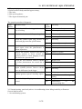
3. CHECKS & ADJUSTMENT
Regular Maintenance Table
The table below lists the recommended intervals for all the required periodic maintenance work
necessary to keep the vehicle at its best performance and economy. Maintenance intervals are
expressed in terms of kilometer, miles and hours, whichever occurs first.
Note: More frequent maintenance may be required on vehicles that are used in severe conditions.
Interval
Item
Valve clearance
Km
Hours
Initial
Every
Every
250km
500 km
1000 km
Initial 20
Every 50
Every 100
hours
hours
hours
I
—
I
Remarks
IN: 0.18±0.05
EX: 0.25±0.05
Idle Speed
I
I
—
850 r/min±50r/min
Spark plug
I
—
I
No carbon deposit,
Gap:0.9~1.1mm
R( Every :6000km )
Air Filter
—
I
C
Fuel Hose, carburetor
—
—
I
Clutch
—
—
I
Drive Belt
—
I
—
Oil Filter
R
—
R
Oil change
R
—
R
Coolant Level
I
I
—
Water Hose & Pipes
I
—
I
Coolant
R( every: 2-year)
I-Check and adjust, or replace if necessary
R-Replace
C-Clean
3-2
R(every :20000km)
R(every: 4-year)
3
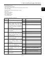
3. CHECKS & ADJUSTMENT
○:Interval
Inspection & Maintenance
Check Item
Part
Steering Steering
System
wheel
Steering
System
Brake
System
Brake pedal
Connecting
rod, oil pipe
& Hose
Hydraulic
brake and
brake disc
Driving
System
Buffer
System
wheel
Suspension
arm
Shock
absorber
Drive-Tr Front axle
ain
system
Rear axle
Gear box
Interval
Daily
1/2 Year
○
Annual
○
Damage
Installation
condition of
steering system
Sway of ball stud
Free play
Brake Efficiency
Looseness,
Slack and damage
○
○
○
○
○
○
○
○
○
○
○
○
○
○
Front and rear
brake fluid level
Brake disc
damage and wear
○
○
○
○
○
○
Tire pressure
○
○
○
Chap and damage
○
○
Groove depth and
abnormal wear
Loosened wheel
nut and axle
Sway of front
wheel bearing
Sway of rear
wheel bearing
Sway of joint
parts, rocker arm
damage
Oil leakage and
damage
Function
Transmission,
lubrication`
Transmission,
lubrication
Transmission,
lubrication
○
○
Item
Operation agility
○
○
Standard
○
○
○
○
○
○
○
○
○
○
○
○
○
○
○
○
3-3
Pedal: rear end 0mm
Brake fluid should be above
LOWER limit
Replace when the thickness of
front brake disc is less than
3mm, rear brake less than
3mm
Front tire :83kPa
(12±1PSI)
Rear tire :83kPa
(12±1PSI)
No wear indication on the
surface of tire (the remained
depth of groove should not be
less than 3mm)
3. CHECKS & ADJUSTMENT
Check Item
Part
Drive Train
Item
Intervals
Daily
Standard
1/2 year
Annual
Final shaft
Looseness of
○
○
○
(Drive
joint parts
shaft)
Sway of
○
Spline
Electrical
Ignition
Spark plug
○
○
System
Device
Ignition
○
○
timing
Battery
Terminal Joint
○
Wiring
Looseness
○
and damage
of joints
Engine
Fuel device
Fuel leakage
○
Throttle
Cooling
Coolant level
system
Coolant
○
○
○
○
○
○
leakage
3-4
3
3. CHECKS & ADJUSTMENT
Check Item
Part
Lighting device
Item
Intervals
Daily
Standard
1/2 year
Annual
Function
○
○
○
and turning
indicators
Alarm and lock
Function
○
Instruments
Function
○
Exhaust pipe
Looseness or damage caused
○
and muffler
by improper installation
device
Function of muffler
○
Frame
Looseness and/or damage
○
Others
Lubrication & grease of frame
○
parts
Abnormal parts
Make sure if there is any
which can be
abnormal with relative parts.
○
determined
when driving
3-5
3. CHECKS & ADJUSTMENT
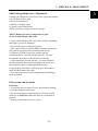
Shift Linkage Inspection / Adjustment
Linkage rod adjustment is necessary when symptoms include:
• No All Wheel Drive light
• Noise on deceleration
• Inability to engage a gear
• Excessive gear clash (noise)
• Shift selectors moving out of desired range
NOTE: Remove necessary components to gain
access to shift linkage cable ends.
1. Inspect shift linkage cable, clevis pins, and pivot bushings
and replace if worn or damaged.
2. Be sure idle speed is adjusted properly.
3. Place gear selector in neutral. Make sure the transmission
bell crank is engaged in the neutral position detents.
4. With two wrenches loosen the outside jam nut
counterclockwise. Turn the outside jam nut 1 1/2 turns.
Perform this procedure on the shift lever end, also.
5. After turning the outside jam nut 1 1/2 turns. Hold the
outside jam nut with a wrench and tighten the inside jam
nut clockwise, until it is tight against the bracket.
6. Repeat Step 4 and Step 5 until the proper adjustment is
made for the transmission cable.
7. Use this procedure to loosen or tighten the shift linkage
cable as needed.
Fuel system and air intake
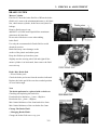
Fuel Lines
1. Check fuel lines for signs of wear, deterioration, damage
or leakage. Replace if necessary.
2. Be sure fuel lines are routed properly and secured with
cable ties. CAUTION: Make sure lines are not kinked or
pinched.
3. Replace all fuel lines every two years.
3-6
3
3. CHECKS & ADJUSTMENT
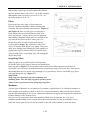
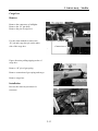
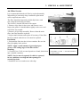
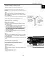
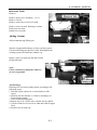
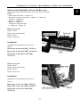
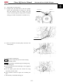
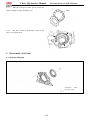
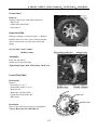
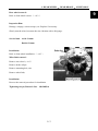
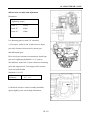
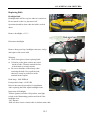
Air Filter Service
It is recommended that the air filter be replaced annually.
When riding in extremely dusty conditions replacement
will be required more often.
The filter should be inspected periodically before each
ride, using the following procedure.
The air box is located rearward of the engine.
1. Remove clips from air box cover and remove cover.
Inspect the gasket. It should adhere tightly to the cover and
seal all the way around.
2. Remove air pre-filter assembly. Do not clean the main
filter, the filter should be replaced.
3. Inspect main element and replace if necessary. If the filter
has been soaked with fuel or oil it must be replaced.
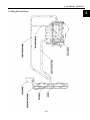
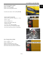
Installation
1. Reinstall the filter into the air box container. Be sure the
filter fits tightly in the air box.
NOTE: Apply a small amount of general purpose
grease to the sealing edges of the filter before
installing.
2. Check air box. If oil or water deposits are found, drain them
into a suitable container.
NOTE: Service more frequently if vehicle is operated
in wet conditions or at high throttle openings for
extended periods.
3. Install air box cover and secure with clips.
3-7
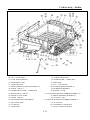
1.JOINT,AIR CLEANER
2. CIRCLIP
3. PRIMARY COVER 4. FILTER ELEMENT
5. TAIL COVER
3. CHECKS & ADJUSTMENT
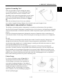
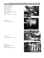
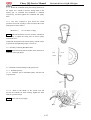
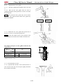
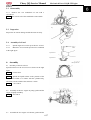
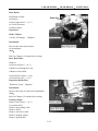
Steering Stem
Park the vehicle on level place, hold steering wheel,
and shake in the direction as illustrated on the right
and see if there is any sway
In case of any sway, check if it is the problem of the
steering stem or other parts and then do the
maintenance accordingly.
In case of sway of the steering stem, tighten the
locknut or disassemble the steering stem for
further check.
Park the vehicle on level place, slowly turn the
steering wheel left and right to see if it can turn
freely.
In case there is any hindrance, check if there is
any interference. If no, check the steering tie-rod
end, and check if the steering stem bearing is
damaged
Note:
Make sure the steering can be operated freely.
An accident may occur if the steering wheel is out of control.
3-8
3
3. CHECKS & ADJUSTMENT
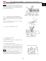
BRAKE SYSTEM
Master Cylinder
Fluid level Check the brake fluid level When the brake
fluid level is near to the minimum(Minimum=1/4H) limit
line, check master cylinder, brake hoses and joints for
leakage.
Remove fluid reservoir cap.
add DOT3 or DOT4 brake liquid till the maximum
(Maximum=H) limit line.
Do not mix with dust or water when adding
brake fluid.
Use only the recommended of brake fluid to avoid
chemical reaction.
Brake fluid may cause damages to the
surface of the plastic and rubber parts.
Keep the fluid away from these parts.
Slightly turn the steering wheel left and right till the
master cylinder is in horizontal, then remove the fluid
reservoir cap.
Brake Disc, Brake Pad
< Wear of brake pad>
Check the brake pad wears from the mark as indicated.
Replace the brake pad if the wear has reached position
of wear limit trough.
Note
The brake pad must be replaced with a whole set.
Checking and replacing the brake disc
Front brake disc thickness: ≤3 mm →Replace
Rear brake disc: ≤3mm →Replace
Min. limited thickness of the front brake disc:3mm
Min. limited thickness of the rear brake disc:3mm
Change The Brake Fluid
< Changing Brake Fluid>
Change the brake fluid once every year.
3-9
3. CHECKS & ADJUSTMENT
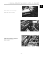
Wheels
3
Lift front wheel on level place, and make sure
there is no loading on the wheels.
Shake the front wheel left and right to check
whether the joint of front wheel is tightened and
check whether it sways.
Not tighten enough ? Tighten it sway: Replace
the rocker arm
Front Toe-in size
Park the vehicle on level place, measure the front
toe-in
Toe-in: B-A=0~10mm
Toe-in out of the range , Adjust the locknut
of tie-rod
Note:
After the toe-in has been adjusted, slowly run the
vehicle to check whether the direction of vehicle
can be controlled by steering wheel.
3-10
3. CHECKS & ADJUSTMENT
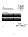
Tire pressure
Check the pressure of the tires with a pressure
gauge.
Note
Check the tire pressure after tires are cooled.
Driving under improper tire pressure will reduce
the comfort of operation and riding, and may
cause deflected wear of the tires.
Specified pressure /tire
Front wheel
Rear wheel
Pressure
96.5±3.5kPa (14±0.5PSI)
96.5±3.5kPa (14±0.5PSI)
Tires sizes
27×9-14
27×11-14
OPTIONAL:
Front wheel
Rear wheel
Pressure
82.5±3.5kPa (12±0.5PSI)
82.5±3.5kPa (12±0.5PSI)
Tires sizes
26×9-14
26×11-14
Tire Tread
Check the tire tread.
Tread Height: if < 3mm, then Replace with new tires
Note:
When the tread height is less than 3mm,
the tire should be replaced immediately.
3-11
3. CHECKS & ADJUSTMENT
Wheel Nut and Wheel Axle
3
Check front and rear wheel axle nuts for looseness
Loosened axle nuts
Tighten
Tightening Torque:
Front wheel axle nut:
180-200N.m (18.3kgf.m-20.3kgf.m)
Rear wheel axle nut:
180-200N.m (18.3kgf.m-20.3kgf.m)
Sway of Wheel Bearing
Lift the front wheel
Make sure there is loading on the vehicle shake
the wheel in axial direction for any sway In case
of any sway, disassemble the front wheel and check
the bearing
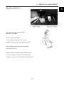
Suspension System
Park the vehicle on lever place, press the vehicle
Several times up and down as illustrated on the right.
In case of any rocking or abnormal noise, check
whether there is any oil leakage from absorbers, or
any damage or looseness of tightening parts.
3-12
3. CHECKS & ADJUSTMENT
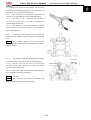
Adjusting the Absorber
Use special tools to adjust the length of absorber
according to loading requirement Turn clockwise
to adjust from high to low.
Gear Shifting
Shift the gear to check for flexibility and gear
engagement Adjust the gearshift rod if necessary
Release the lock nut to adjust the length of gearshift
rod
Fuel Device
Status of the fuel system
Remove the seat
Check the fuel hose for any aging or damage. Aged or
damaged fuel hose: Replace Check if there is cracks
or bending with the fuel hose. Cracked or bended
fuel hose: Replace
3-13
3. CHECKS & ADJUSTMENT
3
Throttle Pedal Check
Check the free play of throttle pedal
Free play: 1.5-3mm
If out of range, then adjust
Loosen locknut of throttle cable turn the
regulator and adjust free play of throttle pedal
After adjusting, tighten locknuts and install
throttle cable sleeve.
Replace with a new throttle cable if the specified
free play could not be acquired by adjusting the
regulator or if there is still stickiness with the throttle.
3-14
3. CHECKS & ADJUSTMENT
Cooling System
Note
● Check coolant level from reservoir tank.
Do not check from radiator.
If the radiator cap is opened while the engine is hot (over 100
℃), the pressure of the cooling system will drop down and the
coolant will get boiled rapidly.
DO NOT open the radiator cap until the coolant temperature
drops down.
●Coolant is poisonous, DO NOT drink or splash it to skin, eyes,
and clothes.
—In case the coolant gets to the skin and clothes, wash with
soap immediately.
—In case the coolant gets into eyes, rinse with plenty of water
and go to consult the doctor
—In case of swallowing the coolant, induce vomit and consult
the doctor.
●Keep the coolant in a safe place and away from reach of
children.
Coolant level
Coolant might reduce due to natural evaporation.
Check the coolant level regularly.
Note
●Coolant can prevent rust and resist freeze.
Ordinary water may cause engine rust or
cracks in winter due to freezing.
●Park the vehicle on level ground for checking
of the coolant. Inclined vehicle body will cause
incorrect judging of the coolant level.
●Check the coolant after the engine is warmed up.
Start and warm up engine.
Stop the engine.
Check if the coolant level is between the upper
and lower limit.
3-15
3. CHECKS & ADJUSTMENT
When the coolant level is below the LOWER limit,
remove reservoir tank cap and add coolant till upper limit.
(Add coolant or diluted original liquid).
Recommended coolant: XYPOWER coolant
Standard density: 50%
( Freezing temperature of coolant varies
according to the different mixture ratio.
Adjust the mixture ratio according to the
lowest temperature in the place where the
vehicle is used.)
If the coolant reduces very fast, check if there
is any leakage. The cooling system may be mixed
with air when there is no coolant in the reservoir
tank and the air should be discharged before
adding coolant.
Coolant Leakage
Check radiator hose, water pump, water pipes
and joints for leakage.
In case of any leakage, disassemble and do
further check. (Refer to Chapter 4)
Check the radiator hose for aging, damages or cracks.
The rubber hose will naturally get aged after a period of service
time. The aged hose may get cracked when the cooling system
is heated. Nip the hose with fingers and check if there are any
tiny cracks.
In case of any abnormal, replace with a new hose.
Check the clamps of the coolant pipes and hose.
Tighten properly in case of any looseness.
Check radiator fins for mud and dust clog or damage.
Correct the bent fins; clean the mud with water and
Compressed air. When the damaged area of the
radiator fin is over 20%, replace with a new
radiator.
Check Water Temperature Gauge
When engine is not working, the water temperature should be in
the “0” position. Start the engine to check if the indicator works. If
the indicator is not working, do the maintenance in time.
3-16
3
4. COOLING SYSTEM
Overhauling Info…………………………4-1
Trouble Shooting…………………………4-2
Check and Maintenance…………………4-3
Reservoir Tank……………………. ……4-5
Adding Coolant………………………4-5
Cooling System Chart…………………4-6
Cooling System Assembly Disassembly
/Installation……………………………4-7
Overhaul Information
Note
● If the radiator cap is opened when the coolant temperature is above 100℃, the pressure of
coolant will drop and get boiled rapidly. The steam jet may cause danger and injury. Cover
the cap with a piece of rag after the coolant temperature goes down and open the cap slowly.
● Inspection of coolant should be done after the coolant is fully cooled.
● Coolant is toxic. Do not drink or splash it to skin, eyes or cloth.
—If coolant splashes in your eyes, thoroughly wash your eyes with water and consult a doctor.
—If coolant splashes on your clothes, quickly wash it away with water and then with soap and
water.
—If coolant is swallowed, induce vomit immediately and see a physician.
—Store the coolant properly and keep it away from reach of children.
● Check radiator fins for mud block and/or damage. Correct the bent fins. Clean off the mud
With water and compressed air. Replace with a new one if the damaged fin area reached 20%.
● The overhauling of the water pump can be done without removing the engine.
● Add coolant through reservoir tank. Do not open the radiator cap except when disassembling the
cooling system for adding or drainage of coolant.
● Do not stain the plastic parts with coolant. In case of any coolant stains, flush with water immediately
After disassembly of the cooling system, check the joints for leakage with a radiator cap tester
(available in the market)
● Refer to Chapter 10 for overhauling of temperature transducer.
Inspection standard
Item
Coolant
Capacity
Thermostat
Full capacity
Reservoir tank capacity
Standard density
Opening pressure of radiator cap
Valve open temperature
Full open Temperature
Full open lift
4-1
Standard
4500ml
3300ml
50%
2
108kpa(1.1kgf/cm )
72±2℃
88℃
3.5-4.5mm
4. COOLING SYSTEM
Trouble Shooting
4
Sharp rise of water temperature
●
●
●
●
●
●
●
●
Faulty radiator cap
Air in cooling system
Faulty water pump
Faulty thermostat (thermostat is not open)
Clogged radiator pipe or cooling pipes
Damage or clogged radiator fin
Coolant is not enough
Faulty or malfunction of fan motor
No rise or slow rise of water temperature.
Faulty thermostat (thermostat is not closed)
Faulty circuit of water temperature display
Coolant leakage
●
●
●
●
●
Faulty water seal
O-rings are aged, damaged or improperly sealed.
Washers are aged, damaged or improperly sealed.
Improper installation of pipes or hoses
Pipes and/or hoses are aged, damaged or improperly sealed
4-2
4. COOLING SYSTEM
Check and Maintenance
Checking coolant density
Note:
Open the radiator cap after coolant is fully cooled.
Open the front cover.
The diagram in the direction of the arrow pulling cable.
Open the front cover.
Remove radiator cap (counter clockwise).
Check with a densimeter if the coolant density
adapts to the local temperature.
Check coolant for stains or impurities.
Inspection of radiator cap
Note
Open the radiator cap after the coolant is fully cooled.
Remove:
Remove bolt 1 and battery panel
Remove radiator cap (counter clockwise)..
Note
Apply coolant on the sealing surface of radiator cap
before attaching the tester to the radiator cap.
Install the radiator cap tester to the radiator cap;
Apply the specified pressure (radiator cap opening
pressure) for 6 seconds and make sure that there is drop in
pressure.
Opening pressure of radiator cap:
2
108~137kpa(1.1~1.4kgf/cm )
4-3
4. COOLING SYSTEM
Pressure testing of cooling system
4
Install the radiator cap tester to the radiator cap;
Apply the specified pressure (radiator cap opening
pressure) for 6 seconds and make sure that there is drop in
pressure.
Note
Do not apply pressure over the specified pressure
2
[108~137kpa(1.1~1.4kgf/cm )], or the cooling system
may be damaged.
In case there is any pressure leakage, check the pipe, joint
parts, joints of water pump and drainage (→4-5).
Replacing Coolant, Air Discharge
Preparation of coolant
Coolant is toxic, DO NOT drink or splash it to skin,
eyes, and clothes.
—If coolant splashes in your eyes, thoroughly wash
your eyes with water and consult a doctor.
—If coolant splashes on your clothes, quickly wash it
away with water and then with soap and water.
—If coolant is swallowed, induce vomit immediately
and see a physician.
—Store the coolant properly and keep it away from
reach of children.
Note
Mix the coolant (undiluted) with soft water according
to the temperature 5℃ lower than the actual lowest
local temperature.
Coolant should be made from undiluted coolant with soft
water.
Standard density of coolant: 30%
Recommended coolant: XYPOWER coolant
(Direct application without having to be diluted)
Drainage of coolant
Remove radiator cap cover
Note
Open the radiator cap after the coolant is fully cooled.
Remove:
Open the front cover (→4-3)
Remove Radiator cap. (→4-3)
4-4
4. COOLING SYSTEM
Reservoir Tank
Remove:
Remove front cover assembly (→2-11)
Remove 2 bolts
Remove water hose of reservoir tank
Remove reservoir tank; discharge coolant;
Flush reservoir tank
Install reservoir tank;
Adding Coolant
Add coolant through filling port.
Start the engine and discharge air from cooling system
Check from filling port that air is fully discharged from
cooling system and install the radiator cap
Remove reservoir tank cap and add coolant
till the full limit.
Note:
Check coolant level when the vehicle is
on an even ground.
Air Discharge
Discharge the air from cooling system according to the
following steps:
1. Start the engine and run it several minutes at idle
speed
2. Quickly increase throttle 3~4 times to discharge air
from cooling system;
3. Add coolant till filling port;
4. Repeat step 2 & 3 till no more coolant can be refilled;
5. Check coolant level in reservoir tank and refill till upper
limit.
6. Install reservoir tank cap.
4-5
4. COOLING SYSTEM
Cooling System Chart
4
4-6
4. COOLING SYSTEM
COOLING SYSTEM ASSEMBLY DISASSEMBLY/INSTALLATION
1. RADIATOR
2. FAN ASSY
3. RADIATOR RESERVE
4. WATER HOSE 1(φ6×φ10×450)
5. CLAMP(φ10)
6. BUFFERING COLLAR
7. BUMPERBLOCK,RADIATOR
8. CLAMP(25-38)
9. INLET PIPE,ENGINE (FRONT)
10. TIE-IN INTAKE PIPE
11. INLET PIPE,ENGINE (MIDDLE)
12. INLET PIPE,ENGINE (REAR)
13. T-JOINT, WATER PIPE
14. CLAMP(13-19)
15. CYCLE PIPE (REAR)
16. OUTLET PIPE,ENGINE (FRONT)
17. OUTLET PIPE,ENGINE (RAER)
18. BOLT,FLANGE(M6×16)
19. CYCLE PIPE (FRONT)
20. EXHAUST VALVE
21. CYCLE PIPE (FRONT)
22. BOLT(M6×20)
23. SPACER BUSH
4-7
24. WATER HOSE 2(φ6×φ10×200)
5. REMOVAL OF ENGINE, TRANSMISSION SYSTEM AND GEARSHIFT
Inspection Information……………5-1
Engine Removal and Installation…5-2
Removal and Installation of Front and Rear
axle……………………………………5-7
Removal and Installation of Gearshift…5-7
Inspection Information
Note:
When removal Engine, please use jack to support the bodywork. Don’t damnify the
frame, body of Engine, bolt and cable etc.
● Please blind up the frame when removal the engine.
● Don’t removal engine from the bodywork when operating as follows:
●
—THROTTLE VALVE BODY, AIR FILTER.
—CVT SYSTEM, CVT COVER.
—FAN COVER,ENGINE.
—IGNITION COIL
—CAMSHAFT POSITION SENSOR、CRANKCASE POSITION SENSOR
● Following operation require removal of engine from vehicle:
—CRANKCASE
Tightening torque:
RUBBER WASHER OF ENGINE(M10×1.25):40~50N.m
ENGINE SUPPORT A(M10×25):40~50N·m
ENGINE SUPPORT B(M10×1.25):40~50N·m
5-1
5
5. REMOVAL OF ENGINE, TRANSMISSION SYSTEM AND GEARSHIFT
Disassembly Engine
Remove cargo box.
Remove seat.
Remove plastic covers.
Remove air filter.
Remove exhaust pipe and muffler
Remove hoop.
Remove water inlet hose of engine
Remove bolt 1
Remove gear shift rod A.
Remove hoop.
Remove water outlet hose of engine.
Remove nut.
Remove the throttle cable,
Remove hoop
Remove circulating water hose
5-2
5. REMOVAL OF ENGINE, TRANSMISSION SYSTEM AND GEARSHIFT
5
Remove all the connector of engine.
Remove the connector of ECU.
Remove tension spring of exhaust pipe.
Remove catalytic converter.
Remove muffler.
5-3
5. REMOVAL OF ENGINE, TRANSMISSION SYSTEM AND GEARSHIFT
Remove the connector of oxygen sensor.
Remove two nuts.
Remove exhaust pipe.
Remove hoop of air filter.
Remove two bolts.
Remove air filter.
Remove hoop of air inlet duct for CVT.
Remove bolt.
Remove air inlet duct of CVT.
5-4
5. REMOVAL OF ENGINE, TRANSMISSION SYSTEM AND GEARSHIFT
5
Remove hoop of air outlet duct for CVT.
Remove bolt.
Remove air outlet duct of CVT.
Remove the CVT disassembly/installation.
15. CVT SECONDARY SHEAVE
29. FLANGE PLATE, CVT SUPPORT
37. CVT SECONDARY SHEAVE
38. ORIENTATION COVER,
SECONDARY SHEAVE
39. WASHER(φ12×φ30×2)
40. SPRING WASHER(φ10)
41. BOLT (M10×115)
42. CVT DRIVER
43. CVT BELT
44. CVT IMPELLER
45. SPACER BUSH, DRIVER
46. WASHER(φ12.5×φ30×3)
47. SPRING WASHER(φ12)
48. BOLT (M12×175)
49. SEAL, CVT COVER (LONG)
50. SEAL, CVT COVER (SHORT)
51. BOLT (M6×12)
52. CRANKSHAFT SENSOR
53. CVT COVER (LEFT)
54. JOINT, AIR INLET DUCT
55. BOLT (M6×15)
56. WASHER(φ6×φ12×1.6)
57. CVT PIN
58. BOLT (M6×25)
59. CVT COVER (RIGHT)
60. CIRCLIP (80-100)
61. RUBBER PIPE (φ85×φ92×60)
62. CVT HOSE, IMPORT WIND
63. EXPANSION SCREW(M8×20)
64. RUBBER PIPE (φ85×φ92×60)
65. BOLT(M6×20)
66. CVT HOSE, EXPORT WIND
Remove fixing nuts of engine.
Remove other fixing nuts of engine as shown below.
5-5
5. REMOVAL OF ENGINE, TRANSMISSION SYSTEM AND GEARSHIFT
Engine and gearbox disassembly/installation
1. ENGINE
2. FAN
3. BOLT,FLANGE(M6×16)
4. FAN COVER
5. BOLT,FLANGE(M8×16)
6. BOLT,FLANGE(M8×160)
7. SPACER BUSH
8. ENGINE SUPPORT A
9. SPRING WASHER(φ10)
10. INNER-HEX BOLT (M10×25)
11. LOCKNUT,FLANGE
(M10×1.25)
12. RUBBER WASHER OF
ENGING
13. CLAMP(φ10)
14. FUEL HOSEΦ6×Φ10.5×400
15. GEAR-BOX
16. COBBRA, ENGINE HOSE
17. STOPPER, ENGINE HOSE
18. CIRCLIP (16-25)
19. BOLT (M12×1.25×45)
20. LOCKNUT,FLANGE(M10×1.25)
21. BOLT,FLANGE( M12×1.25×35)
22. ENGINE SUPPORT B
23. ENVELOP BOARD, ENGINE
24. OUTLET WATER GAP, ENGINE
25. BOLT (M8×35)
26. CVT SUPPORT COVER
27. SPRING WASHER(φ12)
28. BOLT,FLANGE(M12×1.75×30)
29. FLANGE PLATE, CVT SUPPORT
30. BOLT(M10×20)
31. NUT,FLANGE(M12×1.25)
32. BOLT(M10×25)
33. BOLT,FLANGE(M8×25)
34. BOLT,FLANGE(M8×30)
35. STEEL BUSH, STARTING MOTOR
36. STARTING MOTOR
5-6
5. REMOVAL OF ENGINE, TRANSMISSION SYSTEM AND GEARSHIFT
Removal and Installation of Front and Rear Axle
Support the vehicle with jack, make sure the vehicle will not fall.
Remove:
--Plastic parts for frame (→Chapter 2)
--Front and rear wheels and arms(→Chapter 8、Chapter 9)
--Air filter (→Chapter 5)
--gearbox (→Chapter 5)
--Engine (→Chapter 5)
-- Front and rear brake caliper
(→Chapter 8、Chapter 9)
Remove front axle.
Remove bolt 1.
Remove drive shaft (front).
Remove bolt 2.
Remove front axle
Installation
Installation as contradictorily process of
remove.
Bolt torque of front axle(M8):23-25N·m
Bolt torque of front axle(M10):45-50N·m
Bolt torque of front drive shaft (M8):
23-25N· m
Remove rear axle.
Remove bolt 1.
Remove drive shaft (front).
Remove bolt 2.
Remove front axle
Installation
Installation as contradictorily process of
remove
Bolt torque of rear axle (M8): 23-25N·m
Bolt torque of rear axle (M10): 45-50N·m
Bolt torque of rear drive shaft (M8):
23-25N· m
5-7
5
5. REMOVAL OF ENGINE, TRANSMISSION SYSTEM AND GEARSHIFT
Front and rear axle assy disassembly/installation
1. FRONT AXLE
2. FRONT DRIVE SHAFT
3. SPRING WASHER(φ8)
4. BOLT (M8×25)
5. BOLT,FLANGE(M10×1.25×145)
6. BOLT,FLANGE(M10×1.25×85)
7. BOLT,FLANGE(M8×16)
8. LOCKNUT,FLANGE(M10×1.25)
9. HOLDER,FRONT AXLE(FR)
10. HOLDER,FRONT AXLE(RR)
11. AIR HOSE, AXLE(φ6×φ8×450)
12. CLAMP(φ10)
13. REAR AXLE
14. SUPPORT,PARKING CALIPER
15. BOLT(M8×45)
16. CIRCLIP(φ32)
17. BOLT,FLANGE(M12×1.25×115)
18. SUPPORT,REAR AXLE (R)
19. HOLDER,REAR AXLE(RR)
20. LOCKNUT,FLANGE(M12×1.25)
21. COUPLING FLANGE
22. WASHER(φ14×φ28×2)
25. PARKING CALIPER
28. REAR DRIVE SHAFT
23. NUT(M14×1.25)
26. SPRING WASHER(φ8)
29. PARKING DISC PAD
5-8
24. PARKING DISC
27. BOLT(M8×30)
Chery QQ Service Manual
Mechanical Part of SQR 472Engine
CONTENTS
Chapter 1 Reading Instruction ......................................................................................................................................2
1) Reading method of Maintenance Instruction............................................................................................................2
2) Meaning of Marks and Abbreviations ......................................................................................................................3
3) Special Maintenance Tool.........................................................................................................................................4
Chapter 2 Disassembly, Assembly and Maintenance....................................................................................................6
1) Timing Belt...............................................................................................................................................................6
1. Structure Diagram.............................................................................................................................................6
2. Disassembly ......................................................................................................................................................7
3. Installation ......................................................................................................................................................10
2) Camshaft.................................................................................................................................................................13
1. Structure Diagram...........................................................................................................................................13
2. Disassembly ....................................................................................................................................................14
3. Installation ......................................................................................................................................................16
4. Routine Inspection of Valve ............................................................................................................................19
3) Cylinder Head.........................................................................................................................................................22
1. Structure Diagram...........................................................................................................................................22
2. Disassembly ....................................................................................................................................................23
3. Routine Inspection ..........................................................................................................................................23
4) Water Pump ............................................................................................................................................................29
1. Structure Diagram...........................................................................................................................................29
2. Disassembly ....................................................................................................................................................29
3. Cleanup ...........................................................................................................................................................29
4. Routine Inspection ..........................................................................................................................................29
5. Assembly.........................................................................................................................................................29
5) Oil Pump.................................................................................................................................................................29
1. Structure Diagram...........................................................................................................................................30
2. Disassembly ....................................................................................................................................................30
3. Cleanup ...........................................................................................................................................................30
4. Disassembly and Assembly of Engine Oil Pump............................................................................................43
4.1 Structure Diagram.................................................................................................................................42
4.2 Disassembly ..........................................................................................................................................42
4.3 Routine Inspection ................................................................................................................................42
4.4 Installation.............................................................................................................................................44
5. Disassembly of Oil Seal..................................................................................................................................45
5.1 Structure Diagram.................................................................................................................................45
5.2 Disassembly ..........................................................................................................................................46
5.3 Inspection..............................................................................................................................................46
5.4 Assembly of Oil Seal ............................................................................................................................46
6 Assembly..........................................................................................................................................................46
6) Crank Connecting Rod Mechanism........................................................................................................................46
1. Structure Diagram...........................................................................................................................................48
2. Disassembly of Crank Connecting Rod mechanism .......................................................................................48
3. Cleanup ...........................................................................................................................................................49
4. Routine Inspection ..........................................................................................................................................52
5. Assembly of Crank Connecting Rod Mechanism ...........................................................................................53
6-1
Chery QQ Service Manual
Mechanical Part of SQR 472Engine
Chapter 3 Table of Main Fit Clearance for SQR472 Engine ......................................................................................55
Chapter 4 Table of Measurement Parameters of SQR472 Engine ..............................................................................59
Chapter 5 Table of Main Fitting Torque for SQR472 Engine .....................................................................................61
Chapter 6 Positions on SQR472 Engine to be Lubricated ..........................................................................................62
Chapter 7 Positions on SQR472 Engine to be Spread with Sealant............................................................................65
6-2
Chery QQ Service Manual
Mechanical Part of SQR 472Engine
Chapter 1. Reading Instruction
1) Reading Method of Maintenance Instruction
1.1 Auxiliary Materials
If it is required in the operation instruction to prepare the auxiliary materials such as special tools, tools, measuring
instruments and grease in advance, you should list all auxiliary materials required in a table before carrying out each
operation.
Since the ordinary tools, lifter and spare parts are conventional materials used in the maintenance, they are omitted
here.
1.2 Operating Sequence and Structure Diagram
(1) The diagram of structure and components, name of components and installation status are set forth at the
beginning of each chapter or section.
(2) The number in the figure refers to the disassembly sequence of each component. The components which may not
be reused and the tightening torque are indicated in the figure.
① Seal Ring
② Engine Oil Pump Cover Sheet
③ Engine Oil Pump Outer Rotor
④ Engine Oil Pump Inner Rotor
⑤ Cotter Pin
⑥ Oil Drain Valve Spring Seat
⑦ Oil Drain Valve Spring
※: Components which may
⑧ Slide Block
not be reused
⑨ Crankshaft Front Oil Seal
⑩
Unit: N·m(kg·cm)
Engine Oil Pump Housing
1 .3 Content Omitted in this Manual
The following operating procedures have been omitted in this Manual, and they should be carried out in the actual
operation:
(1) Operation relating to the lifter and the small-sized elevator;
(2) Cleaning and wipping of common components;
(3) Relevant visual inspection.
6-3
Chery QQ Service Manual
1 .4
Mechanical Part of SQR 472Engine
Definitions
Standard value
Refers to allowed value during inspection, maintenance and adjustment.
Limit
Refers to the maximum or minimum value that should not be exceeded during
inspection, maintenance and adjustment
Reference
Set the standard value for simple measurement to prevent from its measuring
difficulty and inconsistency to facts.
Difference
Refers to the difference between maximum value and minimum value.
It carries the cases of damaging the vehicle and parts so you should pay attention
to the operation description.
Notice
It records the operation descriptions of cases about person accident.
Warning
2) Meaning of Marks and Abbreviations
Mark
Original Words
Intepretation
RH
Right Hand
Right Hand
LH
Left Hand
Left Hand
FR
Front
Front
RR
Rear
Rear
IN
Intake
Intake
EX
Exhaust
Exhaust
SAE
Society of Automotive Engineers
Society of Automotive Engineers
API
American Petroleum Institute
American Petroleum Institute
SPECIAL
Special Tool
TOOL
Special Tool
T
Torque
Torque
Ay
Assembly
Assembly
S/A
Sub Assembly
Sub Assembly
W/
With
With
M/T
Manual Transmission
Manual Transmission
A/T
Automatic Transmission
Automatic Transmission
T/C
Turbo Charger
Turbo Charger
6-4
Chery QQ Service Manual
Mechanical Part of SQR 472Engine
3) Special Maintenance Tools:
Outside view
Name or symbol
Purpose
Engine disassembly and inspection auxiliary
device
Mount on the engine service
stand
Engine service stand
Disassembly and assembly
of engine
Clamp hole wrench for camshaft timing gears
Disassembly of camshaft
timing gears
Spring bushing puller
Assembly of camshaft Oil
seal
Valve keeper remove tool
Assembly and disassembly
of valve spring retainer lock
Auxiliary tools
Flywheel clamp
Assembly and disassembly
of crankshaft gear
Valve guide punch pin
Disassembly and assembly
of Valve guide
Axial Oil seal replacing device
Oil seal base drive
6-5
Chery QQ Service Manual
Outside view
Mechanical Part of SQR 472Engine
Name or symbol
Purpose
Piston pin puller
Disassembly and assembly
of piston pin
Embeded combination oil seal and helical
gear puller
Installation of oil seal
Crankshaft pulley holding tool
Disassembly and assembly
of crankshaft pulley
Wrench
Disassembly and assembly
of crankshaft driven gear
Replace valve clearance
adjustment gasket
Water pump pulley locking wrench
Assembly of coolant pump
Measuring
tools
Feeler gauge. Micrometer caliper. Ruler. Dial gauge. Cylinder gauge. Caliber. Pressure gauge. Torque
wrench torque wrench
Tool
Piston ring extractor
Oil
Engine Oil, adhesive
6-6
Chery QQ Service Manual
Mechanical Part of SQR 472Engine
Chapter 2. Disassembly, Assembly and Maintenance
Disassemble or assemble the engine with roll over stand.
Disassemble or assemble the engine parts on the roll over
stand.
1) Timing Belt
1. Structure Diagram
① Water pump pulley
② Timing shroud
③ Timing belt
④ Torsional damper
⑤ Timing belt back plate
⑥ Tension pulley
⑦ Camshaft timing pulley
※: Components which may
not be reused.
Unit: N·m(kg·cm)
6-7
Chery QQ Service Manual
2. Disassembly
2.1 Remove the water pump pulley as the view showing.
It will be better of disassembling with special tool.
Torque: 25±1.5 N.m
2.2 Disassembly of Timing Belt Cover
Torque: 6±1N.m
2.3 Disassembly of torsional damper
Use special tools to prevent the gear ring from
rotating. When disassembling the fixing bolts of the
torsional damper, make sure that the marks on the
crankshaft timing pulley match with the timing marks
on the engine oil pump.
2.4 Remove the timing belt back plate.
6-8
Mechanical Part of SQR 472Engine
Chery QQ Service Manual
2.5 Disassembly of tension pulley
2.5.1 Compress the top dead center at the first cylinder
piston. After disassembly of timing cover, pull the
bolt and clockwise rotate the timing gear with
wrench. And then align the timing mark of camshaft
timing gear and the raised mark on camshaft cover;
Mechanical Part of SQR 472Engine
Timing Mark
Timing Mark
2.5.2 Screw off the bolt of tension pulley and remove the
tension pulley.
2.6 Disassembly of timing belt
Notice: Do not use sharp tools like screwdriver during
disassembly of belt.
Notice: Pay attention to the following items during using
the timing belt:
l Do not bend the belt with small angle, or the rigging in
belt will break.
l Do not pollute grease and water because the using
expectancy of belt is short.
l Only clockwise rotate the engine after mounting the
belt.
2.7 Disassembly of crankshaft timing gear
6-9
Clockwise
Chery QQ Service Manual
Mechanical Part of SQR 472Engine
2.8 Inspect the timing belt carefully, and replace new components under any of the following circumstances or when
the mileage is up to the conditions of replacement:
2.8.1 Chap of back-side rubber
2.8.2 Chap of dedendum, chap of separated cord fabric.
2.8.3 Wearing, gear missing and incomplete gear of cord fabric.
Chap
Wearing
Chap
2.8.4
Abnormal wearing of belt flank.
Gear
Fall off with
Abnormal
2.8.5 Notice: Replace the belt as any following situation occurs, even though abrasion cannot be found directly:
The water pump leaks water out, and requires continuing infusion.If the belt is spotted with much oil stains, and the
rubber may be damaged due to expansion, you should replace the belt.
Timing belt model and type
Part number
372-1007081
Width of belt
25.3mm
Tension Pulley of Timing BeltRotate the bolt of tension pulley bracket and hear if it is noisy; check the contacting
surface and look if it is damaged.Model and type of tension pulley of timing belt
Check
if
Part number
372-1007030
Width
27.0mm
Outer diameter
φ50mm
the
out
is
damaged.Timing
belt
model
EF
Type
GL, ZL, GS, ZS
Item
Camshaft timing pulley diameter(mm)
φ110.7+0.1-0.2
Camshaft timing pulley diameter(mm)
φ54.65+0.7-0.13
6-10
and
type
Chery QQ Service Manual
Mechanical Part of SQR 472Engine
Check the timing belt back plate for any deformation.
Standard size of crankshaft timing gear
Width
28.6mm
3. Installation
3.1 Assembly of crankshaft timing pulley.
Timing Mark
3.2 Installation of timing (at the top dead center of the
first cylinder piston)
3.2.1 Put the camshaft timing gear on the front end of the
exhaust camshaft, align the locating slot on the gear with
the locating pin on the end of the camshaft, and then fix
the timing gear with bolts. The tightening torque for the
bolts is 100±5Nm.
Make sure that the clashing mark of crankshaft timing
pulley aligns with the mark of oil pump.
Timing Mark
3.3 Install the tension pulley. After adjust the tension of
timing belt, install the tension pulley bolt and tighten it
with the torque specified. Adjust the tension of the timing
belt acording to the following instruction, and install the
tension pulley.
3.3.1 As indicated in the figure, make the tensioner
swing to the right with a screwdriver so that the distance
between the edge of the tension pulley and the circular arc
of the water pump body is 8mm, and then tighten the
tension pulley bolts with the torque of 25±3Nm.
6-11
Chery QQ Service Manual
Mechanical Part of SQR 472Engine
3.3.2 Rotate the crankshaft along the rotating direction of
the engine for 2 rounds so that the timing mark on the
timing gear of camshaft and crankshaft is matched
respectively, and then tighten the crankshaft belt pulley
bolts.
3.3.3 The force required to press down the central
position between the 2 pulleys at the in-tension side of the
timing belt for about 5mm is:
[Reference]
19.6-29.4N(2.0-3.0kg)
Notice: when the deflection can not reach the standard, it
is necessary to adjust the fixing bolt of tension pulley
mentioned above.
Tighten the fixing bolt of the tension pulley with the torque
as specified. The tightening torque is 25±3N.m
3.4 Assembly of Timing Belt Back Plate.
Notice: Install the timing belt back plate in the direction as
indicated in the right figure.
Inside
3.5 Install the torsional damper with special tools.
3.5.1 Without flywheel
3.5.1.1 Hitch the part of crankshaft pulley with the belt
of special tool.
3.5.1.2 Hold on the handle of the special tool and
prevent the toothed belt from rotating. Tighten the bolts
with the specified torque.
Torque: 98.0±10N.m{10±1kgm}
6-12
Outside
Chery QQ Service Manual
3.5.2
3.5.2.1
3.5.2.2
Mechanical Part of SQR 472Engine
With flywheel
Prevent the gear from rotating with special tool.
Then screw down the bolt of torsional damper.
3.6 Assembly of timing cover.
Mount the sealing strips at the positions as indicated in the
right figure. The sealing strips at the position 1 and 2
should be mounted before the assembly of the cylinder
head assembly, and the sealing strip at the position 3
should be mounted before tightening the water pump.
1
3
Install the timing cover, screw in the bolts with hand and
then tighten them.
Torque: 6±1N.m
3.7 Installation of water pump pulley.
Torque: 6±1N.m
6-13
2
Chery QQ Service Manual
Mechanical Part of SQR 472Engine
2) Camshaft
1. Structure Diagram
(1) Cylinder head chamber cover assembly
(2) Cylinder head cover gasket
(3) Camshaft timing belt
(4) Camshaft cover
※: Components which may
(5) Blanking cover
not be reused
(6) Camshaft bearing cap
Unit: N·m(kg·cm)
(7) Exhaust camshaft assembly
(8) Intake camshaft assembly
(9) Camshaft oil seal
(10) Axial spring retainer ring
(11) Saddle washer
(12) Intake camshaft sub gear
(13) Transmission ring
6-14
Chery QQ Service Manual
Mechanical Part of SQR 472Engine
2. Disassembly
2.1 ① Cylinder head chamber cover assembly;
② Disassembly sequence of cylinder
chamber cover;
head
2.2 Remove the camshaft timing gear with special tool.
Notice: ·The special tool should be made as indicated in
the right figure.
·Use the special tool to prevent the camshaft from
rotating.
2.3 Remove the camshaft bearing cap
2.3.1 The marks on the camshaft gear should match
with each other as indicated in the right figure.
Timing Mark
6-15
Gear of Exhaust
Gear
of
Camshaft
Camshaft
Intake
Chery QQ Service Manual
2.3.2 Position the main sub gear on intake camshaft
with bolts, as can be seen from the right picture.
Mechanical Part of SQR 472Engine
Fixing Bolt
Notice: In order to eliminate the radial force of the
camshaft, the camshaft should be kept at the horizontal
position in the course of disassembly so as to prevent the
damage caused by the excessively high radial force.
2.4 Disassemble the bolts in the order as indicated in the
right figure, and then disassembly the camshaft bearing
cap.
2.5 Remove the spark plug
2.6 Disassemble the sub gear of the camshaft.
2.6.1 If using the special tools, operate as indicated in
the right figure.
Clamp the camshaft and plug the pins of special tool into
the hole on gear; rotate the gear to keep the meshing of
driven gear and driving gear, and then remove the fixing
bolt of driven gear.
Notice: The surface of the camshaft may not be damaged.
2.6.2 If not using the special tools, operate as indicated
in the right figure.
(1) Screw M6 bolts onto the sub gear of the intake
camshaft at the position as indicated in the right figure.
(2) Use the screwdriver to turn the gear as indicated in
the figure, and disassemble the fixing bolts of the sub
gear.
Notice: The surface of the camshaft may not be damaged.
(3) Disassemble the axial elastic retainer ring with
tensioner and remove the saddle spring washer,
transmission ring, and so on.
For Fixing
Bolt
2.7 Camshaft
6-16
Chery QQ Service Manual
Mechanical Part of SQR 472Engine
2.7.1 Measure the camshaft with micrometer caliper. If it
is below to the specified limit, replace with a new one.
Camshaft journal
Unit: mm
Type
EF
Item
ZL, RL GL, GS, ZS
IN
φ23.0-0.02-0.033
EX
φ23.0-0.02-0.033
IN
φ22.9
EX
φ22.9
Standard value
Limit: 0.10
2.7.2
Inspection of camshaft axial clearance
(1) Replace the camshaft when the axial clearance value
measured with dial gauge exceeds the standard value.The
axial clearance of intake camshaft is 0.1~0.170mm.
The axial clearance of exhaust camshaft is 0.1~ 0.173mm.
Limit: 0.18mm.
2.7.3 Inspect the clearance of the engaging tooth of
camshaft
(1) Install the camshaft into the cylinder head.
(2) Confirm the mark forwards on the bearing cap as
well as the axle number, and then tighten the bolts.
(3) Measure the clearance of engaging tooth of the intake
camshaft with dia indicator.
Notice: ·Measure at 4 points on the circle of the piston
·Turn the intake camshaft with special tools.
·Make sure that the marks on the driven gear and
the driving gear of the camshaft match with each
other.
Inspect the clearance of the engaging tooth of camshaft:
Item
Standard value
Limit
Single tootj
0.04-0.13
0.30
3. Installation
3.1 Under the circumstance that special tools are used:
3.1.1
Fix the 2 holes (φ6) of the camshaft gear
assembly with special tool.
3.1.2
Rotate the driven gear to the right with special
tool and tally the mark hole of driven gear with that of
camshaft driving gear, or their marking way complies with
each other, fix the driven gear with bolts.(Thread: M5;
Thread pitch: 0.8)
For Fixing
6-17
Chery QQ Service Manual
3.2 Under the circumstance that special tools are not
available:
3.2.1
Screw the M6 bolts into the camshaft driven gear
at the position indicated in the right figure. Insert a
screwdriver into the gap between the M6 bolt and the
camshaft journal and trun the driven gear rightwards so
that the fitting mark of the 2 gears match with each other
or the tooth head of the 2 gears accord with each other, and
then fix the driven gear with bolts (M5×0.8).
Mechanical Part of SQR 472Engine
Bolt
Notice: Don’t damage the journal, adjust the operation.
3.3 Assembly of camshaft
Notice: Pay attention to the axial clearance of the camshaft
3.3.1 Spread grease on the gear of camshaft and the axial
of cylinder head.
Timing Mark
3.3.2 Remove the fixing bolts for camshaft driven
gear after mounting the camshaft.
3.3.3 Mount the camshaft, align the timing mark as can
be seen from the right picture
Gear
of
Exhaust
3.3.4 Spread oil fully on the cam of camshaft assembly,
gears and axial of cylinder head.
3.4 Tighten the camshaft bearing cap by the order of right
picture.
For Fixing
3.5 Screw off the fixing bolts for driven gear of intake
camshaft assembly.
6-18
Gear of Intake camshaft
Chery QQ Service Manual
3.6 Assembly of camshaft cove
Spread sealant on the position (slot) of camshaft cover as
can be seen from the right picture.
Mechanical Part of SQR 472Engine
Glue Spread Line
3.6.1 Assembly of Camshaft Cover
Tighten the bolts in the order as indicated in the right
figure and with the specified torque.
3.6.2 After spreading oil on the blanking aperture of
cylinder head and the mounting surface of blanking cover,
press the blanking cover with special tool.
Notice:·The blanking cover should be installed in the
direction as indicated in the right figure.
· After being pressed, the blanking cover should be
1±1mm higher than the surface of thecylinder
head.
Outside
3.7 Spread the edge of the camshaft oil seal with oil, and
press it into the cylinder head with M10 bolt (length:
50-60mm) and special tools.
Notice:· If the oil seal is reused, spread it with oil before
pressing it into the cylinder head.
· After removing the bolt, knock it with hand so as to
inspect and confirm it.
3.8 Assembly of camshaft timing gear
After spreading sealant on the bolt, prevent it from rotating
with special tool and screw down the bolt of camshaft
timing gear in specified torque.
Torque: 100±5N.m
Notice: Process the special tools as indicated in the right
figure before using them.
6-19
Chery QQ Service Manual
Mechanical Part of SQR 472Engine
3.9 Installation of cylinder head cover
3.9.1 The old cushion of the timing belt cover which
contacts the cylinder head cover should be removed
completely.
3.9.2 Put the new cushion into the gloove of the timing
belt cover accurately.
3.9.3 Mount the cylinder head cover on the cylinder
head, and tighten the 8 bolts in the order as indicated in the
right figure and with the specified torque.
Torque: 6±1N.m
4
Inspection of valve
4.1
Standard valve clearance:
Valve clearance
Timing
IN
0.18±0.05
EX
0.25±0.05
4.2 Make sure that the timing mark on the camshaft
driving gear is aligned with that on the camshaft driven
gear.
Gear
4.3 Inspect the valve clearance as specified in the figure
below with the feeler gauge
Cylinder 1
Cylinder 2
Cylinder 3
Cylinder4
IN
EX
IN
EX
IN
EX
IN
EX
O
O
O
—
—
O
—
—
4.4 Rotate the camshaft for a round to the position as
indicated in the figure, and then measure the valve
6-20
of
Exhaust
Gear
of
Intake
Chery QQ Service Manual
clearance once again:
Cylinder 1
Cylinder 2
Cylinder 3
Cylinder 4
IN
EX
IN
EX
IN
EX
IN
EX
—
—
—
O
O
—
O
O
If the clearance exceeds the standard value, adjust it by
replacing the adjustment gasket.
Notice: The position at which the measurement result
exceeds the standard value as well as the measurement
result should be recorded.
4.4.1 Rotate the camshaft and make the cam head of the
cylinder which exceeds the standard value faces upwards
and the opening of the valve tappet face inwards.
4.4.2 Rotate the crankshaft and press down the valve
tappet with the crown head of the cylinder cam.
4.4.3 As indicated in the right figure, put special tools on
and around the valve tappet from the inside of the cylinder
head, and then rotate the crankshaft so that the crown head
of the cam face upwards. Press the valve tappet with
special tools and hold on.
4.4.3.1 Pry out the adjustment gasket with screw driver,
remove the gasket inside with magnet.
4.4.3.2
Adjust the thickness of adjustment gasket with
6-21
Mechanical Part of SQR 472Engine
Chery QQ Service Manual
Mechanical Part of SQR 472Engine
micrometer caliper.
4.4.3.3
Select the gasket on the basis of the standard
value of valve tappet
① Intake valve
Select gasket thickness = Unload thickness +
(Measured valve clearance -0.25mm)
② Exhaust valve
Select gasket thickness = Unload thickness +
(Measured valve clearance -0.25mm)
[Reference] The 32 kinds of gasket with different
thickness are listed in the following table:
2.18
2.40
2.62
2.20
2.42
2.64
2.22
2.44
2.66
2.24
2.46
2.68
2.26
2.48
2.70
2.28
2.50
2.72
2.30
2.52
2.74
2.36
2.58
2.80
2.32
2.54
2.76
2.38
2.6
4.4.3.4 Adjust the valve clearance with selected
adjustment gasket.
Notice: Install the adjustment gasket with its identification
mark facing downwards.
Low
4.4.3.5 Rotate the crankshaft so that the crown head of
the cam faces downwards and presses down the the valve.
Pick up the special tool.
4.4.3.6 Rotate the crankshaft for 2-3 rounds and confirm
once again the valve clearance. If it is still beyond the
scope of standard value, adjust and inspect the valve
clearance according to the operation specified in 4.1-4.4.
3) Cylinder Head
1. Structure Diagram
6-22
Chery QQ Service Manual
1
2
3
4
5
6
7
8
9
10
11
12
13
14
Spark plug 20±1Nm
Cylinder Head
Weather Strip I
Cylinder cushion
Adjustment gasket
Valve tappet
Valve spring retainer
Valve spring seat
Valve Spring
Intake valve
Exhaust valve
Valve oil seal
Valve seat
Valve guide
Mechanical Part of SQR 472Engine
※: Components which may not be
reused
2. Disassembly
2.1 Disassembly of spark plug
2.2 There are 8 boltes on the cylinder head. In the course
6-23
Chery QQ Service Manual
of the assembly of cylinder head, slowly tighten these bolts
in the order as indicated in the right figure for several
times untill ther are tightened properly.
Notice: Remove the cylinder head bolts with a torque
socket wrench in the contrary order.
2.3 Disassembly of cylinder head and cylinder head
gasket
Notice: The cylinder head gasket is nonreusable.
2.4 Disassembly of valve adjustment gasket and valve
tappet
2.5 Disassemble the valve spring retainer lock, spring
retainer, spring seat, valve spring, intake valve, and
exhaust Valve etc with special tools.
2.6 Disassembly of valve oil seal and valve spring gasket
2.7 Cleanup
2.7.1 Clean the carbon dust on the valve.
2.7.2 Clean the bottom surface of cylinder head and the
surface of intake and exhaust manifold with scraper knife.
Notice: The surface of the cylinder head may not be
scratched in the course of cleanup.
Do not pollute the intake port and water passage.
3. Routine Inspection
3.1 Cylinder Head
Measure the flatness at each point with ring gauge as
indicated in the figure.
Cylinder head: 0.10mm
Surface of intake/exhaust manifold: 0.10 mm。
3.2 Valve Spring
3.2.1 Measure the square degree of valve spring with
square. Replace if it exceeds the specified value.
Limit: 1.2mm
6-24
Mechanical Part of SQR 472Engine
Chery QQ Service Manual
3.2.2
Mechanical Part of SQR 472Engine
Measure the free state of the spring.
Standard value:
37mm
3.3 Inspection of valve
3.3.1 Check if it is deformed or abrades.
Inspection of valve
Standard value
Limit:
0.10
IN
0.85~1.41
—
EX
1.07~1.36
—
IN
1.0±0.2
0.75
EX
1.0±0.2
0.75
Item
Width of seal
Thickness of top
of valve
Unit: mm
Thickness
Top
3.3.2 Check the clearance of valve guide and valve stem.
3.3.2.1 Measure the inside diameter of valve guide with
dial gauge, the outer diameter of valve stem with
micrometer caliper.
3.3.2.2 Figure out the difference of measured values and
the clearance. If the clearance is beyond the specified
value, replace valve or guide.
Notice: As can be seen from the right picture, at measuring
point, work out the clearance of last abrasion part.
Item
Standard value
Limit: 0.10
Valve guide inside
diameter(mm)
φ5.0
—
Valve guide outer
diameter(mm)
φ5.0
—
IN
0.056~
0.020mm
0.07
EX
0.066~
0.030mm
0.08
Clearance
of
Measurement
Position of
Diameter
Outer
Measurement
Point
Measurement of Valve Guide Inside Diameter
Measurement Point
6-25
Chery QQ Service Manual
Mechanical Part of SQR 472Engine
3.3.3
Replacement of valve guide.
3.3.3.1 Heat the cylinder head with hot water to 80-100
℃.
3.3.3.2 Take out the valve guide from one side of
combustion chamber with special tool, as can be seen from
the right picture.
Notice: The removed valve guide may not be reused.
The intake valve guide and the exhaust valve guide may
not be mis-installed.
IN Use
3.3.3.3 Mount the new valve guide with special tool at
the place as can be seen from the right picture.
Notice: strike the conduit slowly to the position in the
cylinder head; do not strike too far and be careful for size.
The height of the part of valve guide struck into the
cylinder head:
Type
EF
Item
GL, ZL, RL, GS, ZS
Height (mm)
IN
13.71±0.25
EX
12.11±0.25
3.3.3.4 Rub the inside diameter with reamer to reach the
standard clearance value.
3.3.4 Assorted surface of valve
3.3.4.1 Spread with red lead on the assorted surface of
valve. Do not rotate the valve but press lightly and check
the assortment and width.
6-26
EX Use
Chery QQ Service Manual
3.3.4.2
Mechanical Part of SQR 472Engine
Repair of valve seat insert
Notice: The repair of valve seat is always conducted in
the course of the inspection of valve’s fitting position. The
surface repaired should be free from any breakage. Take it
out slowly after the inspection.
3.3.4.3 45wimble surface is assorted standard value.
3.3.4.4 Inspect the fitting position of the valve. The best
position is the center of the valve. If no the valve should be
adjusted.
3.3.4.5 Cut wimble surface at the center of assorted
position with inner 70and outer 30
3.3.4.6
Prepare for polishing of valve seal.
3.4 Assembly of cylinder head
3.4.1 Cylinder head
Pay attention to the following for installing the other
auxiliary part of cylinder head:
3.4.2 Protective tube of spark plug
1. Press the protective tube of spark plug into the
protective tube hole on the cylinder head with the special
auxiliary tool. Before pressing, spread the protective tube
with sealant. The pressing depth is indicated in the right
figure.
Notice: Pay attention to the pressing depth and the
uprightness to top of cylinder head when pressing.
During pressing, the protective tube can not be deformed,
or leaking will be occurred at the cylinder head cover.
Protective Tube of Spark Plug
6-27
Chery QQ Service Manual
3.4.3
Installation
3.4.3.1 Assembly of valve spring washer and valve oil
seal
3.4.3.1.1 Clamp the special auxiliary tool on the top of
valve stem and spread oil around the auxiliary tool and the
inner of new valve oil seal. Then mount it at the position as
can be seen from the picture and pull out the mounting
auxiliary tool of valve oil seal.
[Reference]
Mechanical Part of SQR 472Engine
Auxilary Tool of Valve Spring Assembly
Valve
Valve Oil Seal
Assembly Lower Surface of
After being pressed down, the size of
the oil seal should comply with the value
indicated in the right figure.
Valve Spring
3.4.3.2 Assembly of intake valve and exhaust valve
3.4.3.2.1 Assembly of valve spring.
Notice: The painting is used for recognizing the different
suppliers, so the same engine should use the valve spring
with same painting.
Painting
3.4.3.3 Assembly of valve keeper
Warning: Operate with goggle for protecting the eyes.
·Be care for spring jumping out.
After assembly of valve spring and its seat, press the valve
spring with special tool and mount the valve keeper.
3.4.3.4 Assembly of valve tappet and valve clearance
adjustment gasket
3.4.3.5 Mount the cylinder head gasket and recognize
the direction of front and back.
3.4.4
Assembly of dust seal and cylinder head
6-28
Chery QQ Service Manual
assembly
3.4.4.1 Spread a little oil on the flange side of bolt and
threaded part
Mechanical Part of SQR 472Engine
Oil
Position
3.4.4.2 Tighten the cylinder bolts in the order indicated
in the right figure for 3 times till the torque reaches the
specified value. The tightening torque for each time is set
forth as follows:
First time: 30±2Nm; second time: 50±3Nm; third time:
70±3.5Nm
Torque: 70±3.5N.m
3.4.4.3 Mount spark plug
Torque: 20±1Nm
Notice: Tools should be vertical to prevent the protective
tube of spark plug from distorting, or the oil will leak.
6-29
Spread
Chery QQ Service Manual
Mechanical Part of SQR 472Engine
4) Water Pump
1. Structure Diagram
Components
may not be reused
① O-ring (nonreusable)
② Water pump body
③ Dust seal
2. Disassembly
2.1.○
1 Disassembly O-ring
Notice: The O-ring is nonreusable.
2.2 Screw off 3 bolts and disassemble water pump body.
2.3. Disassembly of dust seal
3. Cleanup
3.1 Clean water pump joint surface.
4. Routine Inspection
4.1 Check if it is deformed.
4.2 Rotate it with hand and inspect whether the rotor
rotates and is lubricated well.
5
which
Assembly
5.1 Mount Dust seal.
5.2 Mount Water Pump Body; torque: 25±1.5N.m.
5.3 Mount The New O-ring.
6-30
Chery QQ Service Manual
Mechanical Part of SQR 472Engine
5) Oil Pump
1. Structure Diagram
Components
which
may not be reused
① Torque for oil pan bolt: 8±2 N.m
② Oil collector
③ Oil collector spacer (nonreusable)
④ Oil pump
⑤ Oil pump spacer (nonreusable)
⑥ Rear oil seal bracket
2
Disassembly
2.1 Screw off the bolts and nuts, and then remove the oil
pan from the cylinder body with special tool (The engine is
placed on the disassemble shelf upside down).
Notice: Don’t make the oil pan flange deform.
6-31
Chery QQ Service Manual
2.2 Remove the engine oil drainer, engine oil collector
gasket
Notice: The oil collector gasket is nonreusable.
2.3 Remove the engine oil pump assembly and the engine
oil pump gasket.
2.4 Remove the rear oil seal bracket.
3. Cleanup
3.1 Remove the old cushion from the oil pan, oil pump
and oil pan bracket with a scraper or shovel.
Notice: Don’t let the fragment of the cushion fall into the
cylinder.
6-32
Mechanical Part of SQR 472Engine
Chery QQ Service Manual
4
Mechanical Part of SQR 472Engine
Disassembly and Assembly of Engine Oil Pump
4.1 Structure Diagram
①
Seal Ring
②
Engine Oil Pump Cover Sheet
③
Engine Oil Pump Inner Rotor
④
Engine Oil Pump Outer Rotor
⑤
Cotter Pin
⑥
Oil Drain Valve Spring base
⑦
Oil Drain Valve Spring
⑧
Slide Block
⑨
Crankshaft Front Oil Seal
⑩
Engine Oil Pump Housing
※ : Components which may
not be reused
Unit: N·m(kg·cm)
4.2 Disassembly
4.2.1 ① O-ring
Notice: The O-ring is nonreusable.
4.2.2 Remove the oil pump cover
Notice: If the screws are tightened, use a screw driver
to remove them as indicated in the figure.
4.2.3 Remove the inner rotor, outer rotor of the engine
oil pump.
6-33
Chery QQ Service Manual
4.2.4
Mechanical Part of SQR 472Engine
Remove the cotter pin
Notice: The cotter pin is nonreusable.
Notice: When removing the cotter pin, be careful not to
let the spring or the spring seat spring out or fall off
abruptly.
Relief Valve
Slide Block
4.2.5
Remove the spring seat of the oil pressure relief
valve for the engine oil pump, the coil spring, oil pump
and oil pressure relief valve etc.
Relief Spring
Spring Seat
4.2.6
Remove the front crankshaft oil seal.
Notice: The oil seal removed may not be reused.
4.3
Routine Inspection
Mark
4.3.1
Inspect the engine oil pump for clearance.
4.3.1.1 According to the marks for inner gear and outer
gear in the engine oil pump, put the gears into the engine
oil pump that is in the cylinder block.
4.3.1.2 Measure the clearance between the inner and
outer gears with a feeler gauge
Standard value: 0.05-0.18mm (average value of 9
positions)
Limit:
0.35 mm
6-34
Chery QQ Service Manual
Mechanical Part of SQR 472Engine
4.3.1.3 Measure the clearance between the rotor and
pump body.
Standard value: 0.10-0.181mm
Limit: 0.25 mm
4.3.2
Inspect the oil pressure relief valve
4.3.2.1 No abrasion or scrape shall be found on the oil
pressure relief valve.
4.4
Installation
4.4.1 After the lip of the new oil seal for front crankshaft
is spread with engine oil, fix it with a special tool.
Special Tool
Notice: ·Use new oil seal
·The oil seal should be left less than 0.5 mm at its
outer edge after it is pressed down.
Pressed Direction
Inner Side
Oil Seal
Below 0.5mm
4.4.2 Assembly of the oil pressure relief valve for engine
oil pump and the cotter pin.
Notice: The cotter pin is nonreusable.
6-35
Chery QQ Service Manual
4.4.3
When the outer gear or inner gear is put into the
engine oil pump, its mark should be seen.
Mechanical Part of SQR 472Engine
Mark
4.4.4
The new weather strip should be fixed in the
groove of oil pump cover.
5. Disassembly of Oil Seal
5.1 Structure Diagram
Components
which
may not be reused
6-36
Chery QQ Service Manual
5.2
Mechanical Part of SQR 472Engine
Disassembly
5.2.1 Remove the rear crankshaft oil seal with a
screwdriver.
Notice: The rear oil seal of the crankshaft is nonreusable.
Lip
5.3
Inspection
Inspect the oil seal for damage and the abrasion at its lip.
5.4
Assembly of oil seal
5.4.1
Spread engine oil over the lip of the new oil seal.
5.4.2
Mount the oil seal with special tool as indicated
in the right figure
Special Tool
Special Tool
6. Assembly
Glue Spread Line
6.1 Assembly of the oil seal seat
Spread sealant over the oil seal seat as shown in the right
figure.
Grease: Loctite 5699
Notice: Spread the liquid sealant on the position of the
oil seal base which is to contact with the cylinder body,
and make sure the width of the sealant is 3-4mm.
Torque: 25±1.5N.m
6.2 Assembly of the new engine oil pump gasket and the
engine oil pump assembly.
Torque: 20±1.5N.m
6.3
Assemble the new engine oil collector gasket and the
6-37
Chery QQ Service Manual
Mechanical Part of SQR 472Engine
engine oil drainer
Torque: 6±1N.m
6.4 Assembly of the oil pan
6.4.1 Clean up the joint surface between the oil pan with
the cylinder.
6.4.2 Spread sealant, then assemble it.
Grease: Loctite 5699
Notice: ·The sealing line should be unbroken with its
diameter being ф3-4mm
·Assembly should take place fifteen minutes
after glue-spreading.
6.4.3 Tighten the bolts in the middle first up to the
specified torque, then the bolts beside them as shown in
the right figure.
Torque: 6±1N.m
Front
6-38
Rear
Chery QQ Service Manual
Mechanical Part of SQR 472Engine
6) Crank Connecting Rod Mechanism
1
Structure Diagram
Components which may
not be reused
① Connecting rod cover
② Connecting rod bushing
③ Piston connecting rod assembly
④ Main bearing cap
⑤ Crankshaft
⑥ Crankshaft bearing bushing
⑦ Thrust plate
⑧ Cylinder body
⑨ First ring
⑩ Second ring
⑾ Steel tape combined oil ring
⑿ Piston
⒀Connecting rod
⒁ Piston pin
6-39
Chery QQ Service Manual
2
Mechanical Part of SQR 472Engine
Disassemble of Crank Connecting Rod Mechanism
2.1 Inspect the axial momentum of the connecting rod
2.1.1 Measure the axial clearance with a dial gauge or
feeler gauge.
Standard value: 0.15-0.25mm
Limit: 1.2mm
2.2 Inspect the connecting rod bushing for its radial
clearance.
2.2.1 Remove the bushing cap.
Notice: The components of each cylinder shall be placed
in order.
2.2.2 Clean the bearing bushing and the axle.
2.2.3 Conduct radial adjustment for the axial diameter of
connecting rod with clearance gauge.
Tighten the bushing cap with specified torque.
Torque: 40±2N.m
Notice: The crankshaft may not rotate.
2.2.4 Remove the bushing cap, measure the maximum
thickness of the searcher.
Standard value: 0.020-0.044 mm
Limit: 0.07 mm
6-40
Chery QQ Service Manual
Mechanical Part of SQR 472Engine
2.2.5
If it is beyond the limit, replace the bearing
bushing.
Notice: Replacing the bearing bushing with the product
of the same manufacturer’s brand. The thickness of the
connecting rod bushing which meets the requirements of
clearance = diameter of big end hold – axial diameter of
connecting rod – standard value of bearing bushing
clearance
Connecting Rod
Connecting Cover
2.2.6
Remove the connecting rod bearing cap and the
connecting rod bearing bushing
2.2.7
Put vinyl-resin protecting jacket on the threaded
part of the connecting rod bolt so as to prevent the bolts
from scraping the cylinder hole and the crannkshaft
connecting rod journal, and then disassemble the piston
connecting rod by using the hammer handle striking it out.
Protection Sleeve
2.3 Inspect the axial clearance of crankshaft
2.3.1 Measure the axial clearance of the crankshaft with
a dial gauge, if it is beyond the limit, it is necessary to
replace the axial thrust plate or the crankshaft.
Standard value: 0.089-0.211mm
Limit: 0.30mm
Item
Standard value
1.9-0.11-0.03
6-41
Chery QQ Service Manual
Mechanical Part of SQR 472Engine
2.4 Inspect the crankshaft for its radial clearance.
2.4.1 Remove the crankshaft bearing cap by softly
tapping with a resin hammer.
2.4.2 Clean the inside and surface of the bearing bushing,
the inside and surface of the bearing cap, the cylinder wall
and journal. Inspect them for abrasion and damage
carefully.
2.4.3 Adjust the radial clearance of the crankshaft with a
clearance gauge, and tighten the bearing bushing cover
bolts with the specified torque.
Torque: 70±3.5N.m
Notice: After tightening the bolts, the rotating torque of
the crankshaft should be less than 1Nm
(The torque of crankshaft without piston connecting rod)
Protection Sleeve
Clearance Gauge
2.4.4 Remove the bearing cap and measure the maximum
width with a clearance gauge. If the measurement result
exceeds the limit, replace the bearing bushing.
Standard value: 0.025-0.069mm
Limit:
0.10mm
Width Compare of Clearance Gauge
2.4.5 Remove the main bearing bushing cap of the
crankshaft, crankshaft, crankshaft bearing bushing and
crankshaft axial thrust plate
Notice: Tighten the bolts for the crankshaft bearing cap
in the order shown in the right figure. Tighten the bolts for
three times, then the torque must be up to the specified
value.
6-42
Chery QQ Service Manual
Mechanical Part of SQR 472Engine
2.5 Disassembly and assembly of the piston and
connecting rod assembly
2.5.1
Remove the first ring, second ring and the oil
ring with a pair of piston ring moving pliers.
Notice: Don’t get the piston and piston ring of each
cylinder confused.
2.5.2
Remove the piston, connecting rod and the
piston pin with special tool.
Disassemble the piston pin with special tool as indicated in
the right figure.
Special Tool
① As indicated in the right figure, disassemble the piston
which is at the state mentioned above with special
tools. Remove the piston pin with special tool, and
then remove the piston and the connecting rod.
3
Special Tool
Cleanup
3.1 Cylinder Body
Warning:
In the course of cleanup, protect your eyes
with eyeglass.
3.1.1
Clean up the cylinder body, cylinder head, oil
pan, oil pump and the oil seal with a flat blade.
3.2 Piston
Warning:
In the course of cleanup, protect your eyes
with eyeglass.
3.2.1
Use an old ring to remove the carbon in ring
groove.
3.2.2
Remove the carbon of parts with scavenger.
Notice: Don’t use hard articles such as metal brush.
6-43
Chery QQ Service Manual
4
Mechanical Part of SQR 472Engine
Routine Inspection
4.1 Cylinder Body
4.1.1 Inspect the top surface of cylinder body for its
flatness
(1) Measure at the six points shown in the right figure
with a ruler and a feeler gauge.
Limit:
0.08mm
4.1.2 Use of bore gauge
Measure the cylinder bore at the positions as indicated in
the right figure with a bore gauge, and figure out the
difference between the maximum value and the miximum
value. If the difference exceeds the limit, repair or replace
the cylinder.
Limit: 0.03mm
[Reference] Roundness: A-B or a-b
Cylindric degree: A-a or
[Reference] Standard
diameter
φ72.00-72.01mm
Upper Stopper Position of Piston
Lower Stopper Position of Piston
of
cylinder:
4.2 Piston
4.2.1
Inspect the piston pin hole for its clearance
Measure the piston pin at several positions with a
micrometer caliper shown in the figure, make the
maximum value as the diameter of pin.
Measurement
Piston Pin
4.2.2
Measure the diameter of piston pin at several
positions with an inner-diameter dial gauge as shown in the
figure, make the minimum value as the diameter of the pin
hole.
Work out the clearance with the difference between the
pin diameter and pin hole diameter, if the difference is
beyond the standard value, replace the piston pin or piston.
Standard value: 0.004-0.009mm
Limit: 0.015mm
6-44
Position
of
Chery QQ Service Manual
4.2.4 Measure the diameter of the piston
4.2.4.1 Measure at about 11 mm to the bottom of the
piston, along the direction vertical to the piston pin.
φ 72
0.013
Standard value:
0.025
4.2.5 Inspect the clearance between the piston ring and
the ring gloove
4.2.5.1 Measure around the ring gloove with a piston
ring and a feeler gauge
Standard value
(mm)
Limit
(mm)
First ring
0.03~0.06
0.12
Second
ring
0.03~0.06
0.11
4.2.6
Inspect the end clearance of piston ring
4.2.6.1 Put the piston ring 45mm below the top surface
of the cylinder hole. Press down the piston ring with the
piston head, and then measure the opening with a feeler
gauge.
Standard value
(mm)
Limit
(mm)
First ring
0.25-0.40
0.65
Second
ring
0.35~0.50
0.65
Oil ring
0.20~0.70
1.00
6-45
Mechanical Part of SQR 472Engine
Chery QQ Service Manual
4.2.7
Inspect the clearance between the piston and
cylinder wall
4.2.7.1 Measure the inner diameter of the cylinder and
the outer diameter of the piston at the positions as
indicated in the right figure. If the measurement results
exceed the limit, replace the piston or cylinder.
Standard value: 0.018~0.030
Limit: 0.10
[Reference] The clearance between the piston and cylinder
bore is controlled by the difference between the minimum
inside diameter of piston hole and the maximum outer
diameter of piston.
4.2.7.2 After replacing the piston or the cylinder body,
confirm the clearance again
Standard value: 0.018~0.030
Measurement position of piston
Outer Diameter
Measurement
position of piston
Inner Diameter
4.3 Crankshaft
4.3.1 Inspect the proper alignment of the main axle
diameter.
4.3.1.1 Measure the proper alignment with a dial gauge,
if the proper alignment is beyond the limit, replace the
crankshaft.
Limit: 0.03mm
Notice: The bending value should be equal to
one-second the run-out value of crankshaft rotating one
circle.
4.3.2
Inspect the crankshaft for the abrasion.
4.3.2.1 Measure the connecting rod journal at the
positions indicated in the left figure with a microcaliper,
and figure out the roundness and cylindricity.
Limit: 0.005mm
4.3.2.2 Measure the connecting rod journal at the
positions indicated in the right figure with a microcaliper,
and figure out the roundness and cylindricity.
Limit: 0.004mm
5
Mechanical Part of SQR 472Engine
Assembly of Crank Connecting Rod
mechanism
5.1 Assembly of the piston connecting rod
6-46
Chery QQ Service Manual
Mechanical Part of SQR 472Engine
5.1.1
Assemble the piston, connecting rod and the
piston pin with special tool following the instructions
below:
5.1.1.1 Spread engine oil over the pin hole of the
connecting rod, assemble according to the group mark and
direction mark of piston and connecting rod.
Mark Forward
5.1.1.2 Assemble the piston and the connecting rod with
special tools shown in the right figure.
Align and Straight
5.1.1.3 Adjust and assemble the piston and connecting
rod as indicated in the right figure. Spread the piston pin
with oil and then assemble the piston and connecting rod
with a oressing machine.
Notice: When pressing in the piston pin, make sure the
fitting direction is correct.
·When the piston pin is pressed into the piston, the
small end of the connecting rod should be heated
to 300℃, and the pin should be aligned properly.
Section Shape
Mark
0
5.2 Install the first and second pistion ring and the oil ring
according to the following instruction:
5.2.1 Installation of piston ring
Make the side with marks face upwards, and then fix it
with piston pin tools.
1st Ring
2nd Ring
Oil Ring
Lower Blade
5.2.2
Mount the steel tape combined oil ring (bushing
ring lower, lower blade, upper blade) firstly, and then
mount the second gas ring, and finally mount the first gas
ring. Opening angles of rings are shown in the figure:
1st Ring
2nd Ring
Front
Rear
Bushing
Ring
Upper Blade
6-47
Chery QQ Service Manual
Mechanical Part of SQR 472Engine
5.3 Resemble the crankshaft main bearing cap,
crankshaft, crankshaft bearing bushing and the crankshaft
axial thrust plate, pay attention to the following:
5.3.1 Assembling the bearing bushing, its raised thrust
block should fit into the locating groove in the cylinder
body.
Notice: The
manufacturer.
bearing bushing is
Thrust Plate
from the same
Oil Tank
Spread Oil on the surface of
Bearing Bushing
5.3.2 Spread the crankshaft bearing bushing (upper
piece) with oil before assemble the crankshaft
Outer Forward of Oil
Tank
5.3.3 Mount the thrust plate on the cylinder body bearing
base and make sure that the side with oil gloove
(crankshaft shank) face outwards.
Notice: Spread the side of oil glove with oil
5.3.4 Fix the crankshaft bearing bushing (lower piece) in
the bearing cap, the bearing bushing should fit into the
thrust groove.
Forward Mark
5.3.5 Spread engine oil over the friction surface of
crankshaft bearing bushing (lower piece), assemble the
bushing according to the mark forwards in the main
bearing cap of the crankshaft.
Axle Diameter Mark
5.3.6 Spread oil over the bolts, within three or two times,
tighten them with specified torque.
Torque: 70±3.5N.m
5.3.7 Rotate the crankshaft after assembly, it should
rotates swiftly, the rotating torque should be less than
1Nm.
6-48
Chery QQ Service Manual
Mechanical Part of SQR 472Engine
5.4 Assemble the piston and connecting rod assembly,
connecting rod bearing bushing and the connecting rod
bearing cap, pay attention to the following:
5.4.1
The opening of compression ring and the
opening of oil ring should be in the specified direction.
5.4.2
The bolts of the connecting rod should be
covered with nylon sleeves for fear of scraping the
cylinder body and the axle.
5.4.3
The surfaces of piston and connecting rod and
other surfaces where relative motion exists should be
spread with engine oil.
5.4.4
Confirm the mark forwards of the piston and
strike it into the cylinder body with the piston ring striking
tool.
Notice: The cylinder number of the piston and
connecting rod assembly should be in accordance with the
cylinder number.
5.4.5
Assemble the connecting rod bearing cap and the
connecting rod bushing, pay attention to the following:
5.4.5.1 Put the cover on the bolt as per the mark
forwards, spread a little engine oil over the joint surface
between the nut and its seat.
5.4.5.2 Tighten the right nut and the left nut alternatively
for several times with specified torque.
Forward Mark
Torque: 40±2N.m
Notice: The connecting rod and the connecting rod
bushing should be of the same subassembly:
.
6-49
Chery QQ Service Manual
Mechanical Part of SQR 472Engine
Chapter 3. Table of Main Fit Clearance for SQR472 Engine SQR472
1
Clearance between Cylinder Hole and Piston Skirt (Piston to Cylinder Clearance)
Name of Component
Size and Tolerance
+0 . 01
Cylinder hole
φ72 0
0.015
Piston skirt
2
φ72 -0.025
Size and Tolerance
Crankshaft main journal
φ42h6–0。016
Bearing bushing
2
Bore of cylinder main bearing
φ46F6 +0.025
0.005
Group S: F720.005
0.01
Clearance or Value of
Interferenc
Remark
- 0.006
Clearance 0.025~0.069
+
0.041
Clearance of Crankshaft Connecting Rod Bearing
Crankshaft
journal
connecting
Size and Tolerance
rod
Clearance or Value of
Interferenc
Remark
0
φ37h6 -0.016
0
Bearing bushing
1.5 -0.006
Bore of connecting rodbig
end bearing
φ40F6 +0.025
Clearance 0.025~0.069
+
0.041
Clearance between Piston Pin and Piston Pin Hole
Name of Component
5
Group X: F720
0
Name of Component
4
Divided into two groups:
Clearance for group X:
0.019mm~0.03mm
Clearance of group S:
0.018mm~0.029mm
Remark
Clearance of Crankshaft Main Bearing
Name of Component
3
Clearance or Value of
Interferenc
Size and Tolerance
Piston Pin Hole
+
0.007
φ18 +0.002
Piston pin
φ18 -0.004
0.001
Clearance or Value of
Interferenc
Remark
Divided into twogroups
Clearance for group A:
0.004 mm~0.0085mm;
Clearance for group B:
0.0045mm~0.009 mm
Notice: When installed
with hand, the piston pin
may pass through the
piston pin hole smoothly
without
any
obvious
obstruction, otherwise the
piston pin should be
replaced.
Inteference between Piston and Small End of Connecting Rod
Name of Component
Connecting rod small end
hole
Size and Tolerance
0.026
φ18 -0.044
Clearance or Value of
Interferenc
Value of Interferenc
0.021~0.043
6-50
Remark
Chery QQ Service Manual
0.001
Piston Pin
6
φ18 -0.005
Fit Clearance between Connecting Rod Body Hole and Bolt Bar
Name of Component
Connecting rod body hole
Clearance or Value of
Interferenc
+
0.015
φ8.08 H7 0
Value of Interferenc
0.008~0.032
Remark
The hole should be processed along
with the connecting rod body.
φ8.08 S6 +0.023
Fit Clearance between Connecting Rod Cover Hole and Bolt Bar
Name of Component
Connecting rod cover hole
Size and Tolerance
Clearance or Value of
Interferenc
+
0.015
φ8.08 H7 0
0.005
Bolt bar
8
Size and Tolerance
+
0.032
Bolt Bar
7
Mechanical Part of SQR 472Engine
Clearance
0.005~0.029
Remark
The hole should be processed along
with the connecting rod body.
φ8.08 f6 -0.014
Radial Clearance of Camshaft Bearing
Name of Component
Cylinder Head
Camshaft
Size and Tolerance
φ26H7
Clearance or Value of
Interferenc
1st bearing cap
0.021
0
Clearance
0.020~0.054
0.020
φ26f6 -0.033
Intake
Cylinder Head
Camshaft
Cylinder Head
Camshaft
φ23H7
1st bearing cap
2nd, 3rd, 4th & 5th bearing caps
0.021
0
Clearance
0.020~0.054
0.020
φ23f6 -0.033
φ29H7
Remark
2nd, 3rd, 4th & 5th bearing caps
1st bearing cap
0.021
0
Clearance
0.020~0.054
0.020
φ29f6 -0.033
1st bearing cap
Exhaust
Cylinder Head
Camshaft
9
φ23H7
0.021
0
Clearance
0.020~0.054
0.020
φ23f6 -0.033
2nd, 3rd, 4th & 5th bearing caps
2nd, 3rd, 4th & 5th bearing caps
Fit Clearance between Tappet Hole and Tappet
Name of Component
Cylinder Head Hole
Tappet
Size and Tolerance
Clearance or Value of
Interferenc
0.021
φ28H7 0
0.020
Clearance
0.020~0.054
φ28f6 -0.033
6-51
Remark
Chery QQ Service Manual
Mechanical Part of SQR 472Engine
Remarks: In the above tables, the capital letter and suffix following the sizes (For example, H7 of φ28H7) mean the
process precision, which are unconcerned with the maintenance and may be ignored in the course of maintenance.
Chapter 4. Table
of
Measurement
Parameters
of
SQR472
EngineSQR472
No.
1
Measuring Items
Acceptance value Remark
Axial clearance of crankshaft
0.089-0.211mm
Assemble the crankshaft and tighten the
main bearing cap bolt
Mount the piston connecting rod
Torque of crankshaft
assembly and tighten the connecting
when rotating at
rod bolt
uniform speed
2
Installing timing belt and spark plug
≤1 Nm
≤5.5Nm
≤6Nm
≤26 Nm
Mount the valve, spring and camshaft (excluding timing belt
and spark plug) on the cyllinder head, tighten the camshaft
bolt, and then measure the torque of the camshaft rotating at
uniform speed
≤32 Nm
3
Distance between the outer edge of steel ball and the front end
of camshaft
5.65±0.5mm
4
Distance between the outer edge of steel ball and the rear end
of camshaft
8.65±0.5mm
5
Axial clearance of intake camshaft
0.10~0.179
6
Axial clearance of exhaust camshaft
0.10~0.253
7
Jumping amount of installation surface of flywheel wearing
piece
0.10mmmax
8
Protrusion height of crankshaft woodruff key
2~2.20mm
9
Intake valve clearance
0.18±0.05mm
10
Exhaust valve clearance
0.25±0.05mm
11
Tension of timing belt (When the middle part of the rigth side
is pressed down for 4-5mm)
200~280N.m
12
Compression pressure of cylinder
13
Tension of generator belt ( When the part between the
generator and water pump is pressed down for 4-5mm)
14
Refilling amount of engine oil (including filter)
10~14bar
98N.m
3.5 Liter
6-52
Chery QQ Service Manual
Mechanical Part of SQR 472Engine
Chapter 5. Table of Main Fitting Torque for SQR472 EngineSQR472
No.
Name
1
Main bearing cap bolt
2
Specification
Quantity Fixing Torque (Nm) Remark
M10X1.25
10
70±3.5
Connecting rod cover bolt
M8X1
8
40±2
3
Oil pump bolt
M8X1
6
20±1.5
4
Nut (oil collector – oil ppump)
M6
2
6±1
5
Bolt (oil collector – cylinder body)
M6
1
6±1
6
Water pump bolt
M8X1
6
25±1.5
7
Rear oil seal bracket bolt
M8
5
25±1.5
8
Drain plug
M12
1
45±3
9
Oil pan bolt
M6
19
6±1
10
Bolt connecting exhaust camshaft with flange
(hexagonal)
M6
4
6±1
11
Exhaust camshaft locking nut
M40X1.5(L)
1
100±5
12
Cylinder head bolt
M10X1.25
10
70±3.5
13
Camshaft bearing cap bolt
M6
19
9±1
14
Cylinder head chamber cover bolt
M6
8
4.5±0.5
15
Camshaft position sensor bolt
M8
1
10±1
16
Bolt (knock sensor)
M8
1
20±1.5
17
Camshaft timing gear bolt
M12X1.25
1
100±5
18
Tension pulley bolt
M10
1
25±3
19
Timing cover bolt
M6
7
6±1
20
Engine oil gauge pipe bolt
M6
21
Flywheel assembly bolt
22
Thermoregulator shell bolt
23
Oil filter conncetor
3/4"-16
40±2.5
24
Oil filter
3/4"-16
20±1.5
6±1
M10X1.25
6
70±3.5
M8
2
10±1
6-53
Chery QQ Service Manual
Mechanical Part of SQR 472Engine
25
Intake/exhaust stud
M8
16
10±1
26
Intake pipe nut
M8
8
25±1.5
27
Ignition coil bracket assembly bolt
M8
2
20±1.5
28
Front lifting lug bolt
M8
2
20±1.5
29
Exhaust pipe nut
M8
8
25±1.5
30
Exhaust pipe thermal shroud bolt
M6
3
6±1
31
Bolt on crankshaft pulley & torsional damper
assembly
M12X1.25
1
100±5
32
Water pump pulley bolt
M6
4
6±1
33
Water temperature sensor
M12X1.5
1
15±1.5
34
Oil pressure switch
1
30±2
35
Spark plug
M14X1.25
4
20±1
36
Fixing Bolt of spark plug cover board)
M6
8
2.5±0.5
37
Bolt (intake pipe front bracket)
M8
1
20±1.5
38
Bolt (intake pipe rear bracket)
M8
4
20±1.5
39
Bolt (throttle cable)
M6
2
6±1
40
Bolt (gas-oil spearator bracket)
M6
2
6±1
41
Bolt (throttle valve casing)
M6
4
6±1
42
Oxygen sensor
M18X1.5
1
40±2
43
Bolt (intake temperature & pressure sensor)
M4
1
3±1
44
Fixing bolt of fuel guide rail
M6
2
7±1
45
Ignition coil bolt
M6
3
5±1
6-54
Spread glue
Chery QQ Service Manual
Mechanical Part of SQR 472Engine
Chapter 6. Positions on SQR472 Engine to be Lubricated
Type of lubricating oil: Engine lubricating oil
Designation of lubricating oil: SAE10W/30-50(SF Class)
No.
Position to be lubricated
1
Joint surface of connectong rod bolt head
2
Screw of connecting rod bolt
3
Exicrcle of piston pin
4
Inner wall of piston pin hole
5
Piston and piston ring
6
Inner wall of cylinder hole
7
Crankshaft main neck
8
Connecting rod shaft neck
9
Upper & lower main bearing bushing (inside)
10
Upper & lower connecting rod bearing bushing (inside)
11
Crankshaft thrust plate (the side of oil gloove)
12
Front oil seal and crankshaft front oil seal journal
13
Rear oil seal and crankshaft rear oil seal journal
14
Valve seat hole
15
Valve tappet and valve pipe hole
16
Excircle and hole of valve tappet
17
Camshaft journal and bearing base hole
18
Camshaft driving gear
19
Edge and excircle of oil seal
20
Oil seal journal and oil seal base hole
21
Surface oil filter sealing gasket
6-55
Remark
Chery QQ Service Manual
Mechanical Part of SQR 472Engine
Chapter 7. Positions on SQR472 Engine to be Spread with Sealant
SQR472
Form and amount of
Position to be spread with
No.
Remark
Type of sealant
sealant (reference)
sealant
1
Joingt surface of oil pan
Loctite 5699
ф(3~4)mm
2
Rear oil seal bracket
Loctite 5699
ф(3~4)mm
3
Valve chamber cover
Loctite 5699
ф(3~4)mm
4
Joint surface if timing gear chamber
cover
Loctite 5699
ф(3~4)mm
5
Joint surface of camshaft cover
Loctite 5699
ф(3~4)mm
6
Sealing surface of the bowl shaped
plug of cylinder head
Loctite 11747
Spread uniformly
7
Flywheel bolt
Loctite 204
0.125(ml)×6
Pre-spread @3
Intake pipe stud
Loctite 262
0.125(ml)×7
The part screwed into
the cylinder head
Exhaust pipe stud
Loctite 262
0.125(ml)×6
The part screwed into
the cylinder head
Camshaft timing gear bolt
Loctite 243
0.2ml
Oil collector stud
Loctite 243
0.08(ml)×2
The part screwed into
the oil pump
Screw of thermoregulator shell
fixing bolt
Loctite 243
0.08(ml)×2
The part screwed into
the cylinder head
8
9
10
11
12
6-56
7. FUEL INJECTOR SYSTEM
Overhaul Info…………………………………………………………………7-2
Fuel Injector System Disassembly/ Installation………………………………7-3
High Pressure Fuel Line Disassembly/ Installation…………………………7-4
Throttle Body Disassembly/Installation………………………………………7-4
Fuel rail with injector assy Disassembly/Installation…………………………7-5
Fuel injector Removal/Assembly………………………………………………7-5
7-1
7
7. FUEL INJECTOR SYSTEM
Overhaul Info
CAUTION
NOTE
Gasoline is highly flammable, therefore smoke and fire are strictly forbidden in the work
place. Special attention should also be paid to sparks. Gasoline may also be explosive when it
is vaporized, so operation should be done in a well-ventilated place.
Do not over twist or bend the cables. The twisted cables may cause poor operation.
Loose the high pressure fuel line before disassembly, discharge the fuel in the high pressure fuel
line and put it in a container.
When the body of throttle valve is disassembled, the air intake shall be covered by dishcloth or tape,
for avoiding the entry of other objects into the engine from the air intake side of the engine.
When the vehicle will be stored for more than one month, the gasoline in the high pressure fuel line
and cap of the fuel injector must be discharged. Otherwise, the gasoline will age and form colloidal
elements which may block the nozzle of fuel injector, therefore the engine cannot start or the rotate
speed is unstable.
Overhaul Info
Engine Starting Failure
Too much fuel in the engine.
-Ail filter clogged.
-Idle air pipe clogged.
No fuel in the injector.
-Fuel filter clogged.
High pressure fuel line clogged.
-Fuel injector clogged.
Hard Starting/Stall After Starting, Unsteady
Idle Speed
Idle air pipe clogged.
Fuel system clogged.
Ignition system not functioning properly.
Fuel tank cap clogged.
7-2
7. FUEL INJECTOR SYSTEM
Fuel Injector System Disassembly/ Installation
1. FUEL TANK
2. FUEL PUMP
3. “0”SEAL RING(ф6×ф100)
4. HOOP(φ120×2)
5. JOINT,FUEL HOSE
6. CLAMP(13-19)
7. FUEL HOSE (300mm)
8. BOLT,FLANGE(M8×16)
9. FUEL FILTER ASSY
10. FUEL HOSE (400mm)
11. PROTECTIVE SLEEVE, FUEL TANK CAP
12. CAP, FUEL TANK
13. SUPPORT, FUEL TANK(L)
14. BOLT,FLANGE(M6×12)
15. SUPPORT, FUEL TANK(R)
16. CLAMP(φ10)
17. LOCKNUT,FLANGE(M6)
18. INLET WINDPIPE (FRONT)
19. INLET WINDPIPE (MIDDLE)
20. RELAY, CARBON CANISTER
21. INLET WINDPIPE (RAER)
22. CARBON CANISTER
23. DEAD PLATE, CARBON CANISTER
24. RIVET (5×20)
7-3
7
7. FUEL INJECTOR SYSTEM
High Pressure Fuel Line Disassembly
Loosen the special fuel line clamp on fuel injector cap.
loosen the special fuel line clamp on fuel tank.
Disassemble High pressure fuel line.
NOTE: Use container to keep the remaining fuel
from high pressure fuel line, when loosening
the special fuel line clamp.
High Pressure Fuel Line Installation
Reverse the disassembly procedure for installation.
Use clamp calliper to install the special fuel
line clamp.
Throttle Body Disassembly
Remove the connector of throttle valve opening sensor.
Remove the connector of idling solenoid valve sensor.
Loosen locknut, remove adjust nut and remove the
throttle cable from throttle rotory sleeve.
Loosen air filter clamp.
Remove intake tube of air filter.
Remove 2 clamps and remove circulating water hose.
Remove 4 bolts and remove throttle body.
NOTE: Do not adjust the bolt on throttle body.
Do not remove the cap on throttle body.
Throttle Body Installation
Reverse the disassembly procedure for installation.
7-4
7. FUEL INJECTOR SYSTEM
Fuel rail with injector assy disassembly
Disassemble the special high pressure fuel
Remove the strap and fuel injector connector.
Disassemble 2 bolts and remove fuel rail with
injector assy.
Fuel rail with injector assy installation
Reverse the disassembly procedure for installation.
Fuel injector removal
Use Slotted screwdriver to remove snap spring.
Remove fuel injector from fuel rail with
injector assy.
Fuel injector assembly install
Install fuel injector into the fuel rail with
injector assembly.
Press the snap spring into groove of fuel
injector snap spring.
7-5
7
8 FRONT WHEEL, FRONT BRAKE,SUSPENSION,STEERING
Overhaul Info……………………..…8-1
Troubleshooting………………….…8-2
Front Wheel………………………...8-3
Brake System…………………………8-4
Suspension……………………………8-7
Steering………………………………8-12
Overhaul Information Operating cautions Notes
● Securely support the vehicle when overhauling the front wheel and suspension system.
● Refer to chapter10 for overhaul and inspection of lighting, instruments and switches.
● Do not overexert on the wheel. Avoid any damage to the wheel.
● When removing tire, use the special tire lever and rim protector.
Maintenance Standard
Item
Rim
Vibration
Tire
Front
brake
Standard
Longitudinal
Lateral
Remained groove
Tire pressure
0.8mm
0.8mm
-
12±0.5PSI(82.5±3.5KPa)
-
-
0mm
-
Tightening Torque
Nut, Tie-rod
20-30 N·m
Lock nut, steering stem
20-30N·m
180-200 N·m
Fixing bolt/nut, absorber(front)
30-40 N·m
Fixing bolt/nut, absorber(rear)
30-40 N·m
Nut, front/rear rim
40-50 N·m
Nut, rear wheel axle
2.0mm
2.0mm
3.0mm
12±0.5PSI(82.5±3.5KPa)
Free play(brake lever)
Nut, front wheel axle
Service Limit
180-200 N·m
8-1
8 FRONT WHEEL, FRONT BRAKE,SUSPENSION,STEERING
8
Troubleshooting Heavy
Steering
Wheel Cannot Turn Freely
● Steering bearing is damaged or worn
● Inner & outer bearing races are damaged,
worn or stepped
● Steering stem is distored
● Tire pressure is too low
● Worn tire
● Faulty wheel bearing
● Front wheel axle is bended
● Brake drag
● Faulty steering structure
Front Suspension is Too Soft
Shaking Steering Wheel
●
●
●
●
●
●
●
●
●
Steering wheel is not well tightened
Steering stem is loosened or not well installed
Mount seat, steering wheel is not well tightened
Bearing is damaged
Right and left shock absorbers are not matched
Deflected tires
Deformed frame
Worn tiers
Shaking of wheel bearing
● Weakened front shock absorbers
● Tire pressure is too low
Front Suspension is Too Hard
● Front shock absorber is bended
● Tire pressure is too high
Noise with Front Absorbers
● Faulty front shock absorbers
● Loosened tightening parts of front
absorbers
Vibration of Front Wheel
Poor Brake Efficiency
● Wheel rim distorted
● Faulty brake adjustment
● Stained brake disc
● Worn brake shoes
● Air in brake hose
● Faulty wheel bearing
● Faulty tire
● Improper balance of wheels
● Improper tightening of wheel axle
8-2
8 FRONT WHEEL, FRONT BRAKE,SUSPENSION,STEERING
Front wheel
Removal
Securely support the front wheels Remove:
--Wheel cap
--4 bolts from wheel hub
--Front wheel
Inspection Rim
Damage, warpage or serious scrapes: →Replace
Replace with a new one, if any. Slowly turn the
wheel, measure the rim vibra-tion with a dial
gauge.
Service limit: Axial: 2.0mm
Radial: 2.0mm
Assembly:
Press rim into wheel
Install rim on the wheel hub
Tightening Torque: Bolt, Wheel Hub:40-50 N·m
Front Wheel Hub
Disassembly
Remove:
--Front wheel (→8-3)
--Front brake caliper (→8-4)
--Rim axle nut
--Brake disc and wheel hub
--4 bolts from front brake disc
--Wheel hub
Installation
Reverse the removal procedure for installation.
Torque, Rim axle nut: 180-200N· m
8-3
8 FRONT WHEEL, FRONT BRAKE,SUSPENSION,STEERING
Brake System
8
Front brake caliper
Removal
Remove:
--Front wheel(→8-3)
--2 bolts from arm
--Front caliper
Inspection
Check brake caliper for cracks and tightening
parts for oil leakage.
Replace if any.
Installation
Reverse the removal procedure for
installation.
Tightening Torque
Fixing Bolt, Brake Caliper: 45-50N· m.
8-4
8 FRONT WHEEL, FRONT BRAKE,SUSPENSION,STEERING
Brake Disc
Removal
Remove:
--Front wheel(→8-3)
--Brake caliper(→8-4)
--Front brake disc and wheel hub
--4 bolts from brake disc
--Brake disc
Inspection:
Brake disc thickness: <3mm →Replace
Installation
Install brake disc
Tightening Torque
Fixing bolt, brake disc:40-50N·m
Brake Master Cylinder Disassembly
Remove:
--Blot 1
--Cotter pin
-- Pin shaft.
Do not remove brake master cylinder from vehicle
unless when replacing master cylinder assembly.
Note:
Do not hang master cylinder on brake hose.
Do not put the master cylinder upside down to
avoid possible entrance of air into brake system.
Keep the master cylinder in the installation
position.
Proper routing of brake hose.
Check brake efficiency after installation.
8-5
8 FRONT WHEEL, FRONT BRAKE,SUSPENSION,STEERING
Brake Pedal Removal
8
Remove:
--Cotter pin
-- “E” clamp spring
-- Brake Pedal
Seperate Brake Pedal from vehicle
Disassembly of front brake master cylinder
(→ 8-5)
Installation
Reverse the removal procedure for installation.
NOTE
Do not put the master cylinder upside down to
avoid possible entrance of air into brake system.
Keep the master cylinder in the installation
position.
Refer to Chapter1 for proper routing of brake
hose.
Check brake efficiency after installation.
8-6
8 FRONT WHEEL, FRONT BRAKE,SUSPENSION,STEERING
Front Left Suspension
NOTE:
DO NOT
Remove both left and right suspension
at the same time to avoid fall down of
the vehicle.
Park the vehicle on a level ground and
securely support front part of the
vehicle.
Removal:
Remove:
--Front wheel(→8-3)
--Front wheel hub(→8-3)
--Front brake caliper(→8-4)
--Bolt1, Nut1.
--Shock absorber.
--Bolt2, Nut to Bolt2 for Front Left Arm (Upper)
--Bolt2, Nut to Bolt2 for Front Left Arm (Lower)
-- Remove steering tie-rod ball pin slot nut 3
-- Remove steering tie-rod.
Pull up joint knuckle from the driveshaft, remove
front left suspension assy.
8-7
8 FRONT WHEEL, FRONT BRAKE,SUSPENSION,STEERING
1. COTTER PIN(3×25) 2. NUT(Rear wheel axle)
3. FRONT WHEEL HUB 4. FRONT BRAKE DISC
5. BOLT( M10×25)
6. CIRCLIP (φ72)
7. BEARING
8. FRONT STEERING
KNUCKLE(L) 9. FRONT STEERING KNUCKLE(R)
10. BOLT,FLANGE(M8×55)
11. LOCKNUT,FLANGE(M8) 12. NUT(M10×1.25)
13. PIN, SPLIT(2.5×20) 14. CIRCLIP(φ32)
15. JOINT,ARM BALL 16. SCREW CAP,DRIVE
AXLETREE M12
17. PIN, SPLIT(3×30)
18. FRONT LOWER ARM
(UPPER)
19. FRONT LEFT ARM
20. FRONT RIGHT ARM (UPPER)
Disassembly
Disassembly
Front Left Shock Absorber
Disassembly
ATTENTION: You do not need to remove any other
parts if you only replace the front suspension.
Park the vehicle on a level ground,
Remove front left shock absorber’s bolt, nut installed
in arm.
Remove front left shock absorber.
Inspection
Inspect the shock for oil leakage, oil seal damage,
destroy, replace if needed.
8-8
21. BOLT,FLANGE(M10×1.25×50)
22. LOCKNUT,FLANGE(M10×1.25)
23 . BOLT,FLANGE(M10×1.25×90)
24. BUSH ,ARM 25. CENTER SPACER
26. FRONT SHOCK ABSORBER
27 . FRONT CV JOINT(L)
28. FRONT CV JOINT(R)
29. SUSPENSION PROTECTOR(L)
30. SUSPENSION PROTECTOR(R)
31. SCREW,TAP(ST4.2×20)
8
8 FRONT WHEEL, FRONT BRAKE,SUSPENSION,STEERING
Installation
Reverse the removal procedure for installation.
Refer to front left shock absorber for removal,
installation and inspection of front right shock
absorber.
Arm Assembly
Attention: There are 8 suspension arms in the
vehicle, they dismantle, inspection and assemble
in the same way. So here only introduce the way
to dismantle, inspection and assemble the front
left upper arm and the front right lower arm.
Other arm assemble refers to the above.
Front Right Suspension
Disassembly
Front Right Shock Absorber
Disassembly
NOTE:
DO NOT
Remove both left and right suspension
at the same time to avoid fall down of
the vehicle.
Park the vehicle on a level ground and
securely support front part of the
vehicle.
ATTENTION: You do not need to remove any
other parts if you only replace the front
suspension.
Park the vehicle on a level ground,
Remove front right shock absorber’s bolt, nut
installed in arm.
Remove front right shock absorber.
Removal:
Remove:
--Front wheel(→8-3)
--Front wheel hub(→8-3)
--Front brake caliper(→8-4)
--Bolt1, Nut1.
--Front Right Shock absorber.
Inspection
Inspect the shock for oil leakage, oil seal damage,
destroy, replace if needed.
--Bolt, Nut to Bolt for Front Right Arm (Upper)
--Bolt, Nut to Bolt for Front Right Arm (Lower)
-- Remove steering tie-rod ball pin slot nut
-- Remove steering tie-rod.
Pull up joint knuckle from the driveshaft, remove
front right suspension assy.
8-9
8 FRONT WHEEL, FRONT BRAKE,SUSPENSION,STEERING
Constant Velocity Drive Shaft
NOTE: The removal, inspection and installation
of Left and Right Constant Velocity Drive Shafts
of the Front/Rear Axles are the same. The
following will give instruction only on the removal,
inspection and inspection of Left Constant Velocity
Drive Shaft of Front Axle. Refer to Left Constant
Velocity Drive Shaft for removal, inspection and
installation of other drive shafts.
Left Constant Velocity Drive Shaft, Front Axle
Removal
NOTE: Maintenance of Left Constant Velocity
Drive Shaft of Front Axle only
does not require removal of Front
Suspension.
Remove:
--Front left wheel(→ 8-3)
--Front left brake caliper(→ 8-4)
--Front left wheel hub(→ 8-3)
Check dust boot.
Damaged dust boot: → Replace
Shake constant velocity drive shaft, check
the agility of rzeppa universal joint, free
turning of bearing, and any gap between rzeppa
constant velocity joint and spline.
Stagnated turning, noise, gap with spline:
→ Replace
Warning:
An accident may occur if the rzeppa
constant velocity joint cannot turn
freely because of the loss of control
of wheel steering.
Installation
Press ball pin into arm with special tool.
Reverse the removal procedure for installation.
Note: No shaking with the installed left
and right arms. Replace arms if any. Tightening
Torque:45~ 50N·m
8-10
8
8 FRONT WHEEL, FRONT BRAKE,SUSPENSION,STEERING
Steering System
Cover, Steering Stem
Removal
Remove cover, steering stem(→Chapter 2)
Combination Switch
Removal
Remove combination switch(→ 2-3)
8-11
8 FRONT WHEEL, FRONT BRAKE,SUSPENSION,STEERING
8
Rear View Mirror
Removal
Remove left and right rear view mirrors.
Note: Left rear view mirror is right-threaded.
Turn counter clockwise for
removal.
Note: Right rear view mirror is left-threaded.
Turn clockwise for removal.
8-12
8 FRONT WHEEL, FRONT BRAKE,SUSPENSION,STEERING
Steering Stem
Removal
Remove:
--Steering wheel(→ 2-2)
-- cover, steering stem(→ 2-2)
--Combination switch(→ 2-3)
--Bolt
--Shaft assy., steering joint
--Steering stem
8-13
8 FRONT WHEEL, FRONT BRAKE,SUSPENSION,STEERING
Installation of Combination Switch
8
Install combination switch(→ 2-11)
Insert main cable with connector of combination
switch.
8-14
8 FRONT WHEEL, FRONT BRAKE,SUSPENSION,STEERING
Installation of Steering Wheel
Install steering wheel(→ 2-2)
Steering System
1. STEERING ASSY
2. LOCKNUT,FLANGE(M8)
3. BOLT,FLANGE(M8×16)
4. BOLT,FLANGE(M8×90)
5. STEERING SHAFT
6. BOLT,FLANGE(M8×25)
7. SPRING WASHER (Ф8)
8. BRACKET,STEERING STRENGTHENER
9. BOLT,FLANGE(M8×25) 10. STEERING STRENGTHENER 11. FLANGE,STEERING
STRENGTHENER
12. BEARING 13. BOLT,FLANGE(M8×30) 14. CIRCLIP(ф30)
15. OIL SEAL,STEERING STRENGTHENER 16. STEERING SHAFT(TOP)
17. GASKET(ф14×ф26×3)
18. SPACER BUSH (NYLON)
19. LOCKING NUT(M8)
20. SPACER BUSH (NYLON) 21. BOLT, STEERING COLUMN 22. LOCKING NUT(M6)
25. STEERING COLUMN
23. GAS SRPING,STEERING COLUMN 24. BOLT(M6)
26. SPRING WASHER
27. CORE SHAFT, STEERING
28. STEERING WHEEL ASSY
29. DECORATING COVER
30. BOLT (M5×15)
8-15
9. REAR WHEEL 、REAR BRAKE 、SUSPENSION
Overhaul Info………………………………9-1
Troubleshooting……………………………9-2
Rear wheel…………………………………9-3
Rear brake………………………………9-4
Rear suspension…………………………9-5
Overhaul info:
Note:
● Securely support the vehicle when overhauling the rim and suspension system.
● Use genuine parts of bolts and nuts for rear rim and suspension.
● Do not overexert on the wheels to avoid possible damage to the wheels.
● When removing tire from rim, use special tire lever and rim protector to avoid
damage to the rim.
Overhaul standard
Item
Rear
wheel
Rear
brake
Standard
Rim
Longitudinal
vibration Horizontal
Tire
Remained
Tire Tread
Tire
pressure(front)
Tire
pressure(rear)
Brake pedal Free Play
Limit
-
-
2.0mm
2.0mm
-
3.0mm
12±0.5PSI(82.5±3.5KPa)
-
12±0.5PSI(82.5±3.5KPa)
-
0mm
-
Tightening torque
Rear wheel axle nut
180-200N.m
Rim mounting bolt
40-50N.m
Front mounting bolt, Shock absorber
30-40N.m
Rear mounting bolt, Shock absorber
30-40N.m
9–1
9
9. REAR WHEEL 、REAR BRAKE 、SUSPENSION
Troubleshooting
Rear wheel wobbles
●
●
●
●
●
●
Rim warpage
Faulty tire.
Tire pressure too low
Improper wheel balance
Improper tightening of wheel axle nut
Loosened wheel nut
Rear shock absorber is too soft
● Weak spring.
● Oil leakage from rear shock absorber
Rear shock absorber is too hard.
● Bent rear shock absorber
● Tire pressure is too high
Poor brake efficiency
● Improper brake adjustment
● Stained brake pad or brake disk
● Worn or damaged brake pad
9–2
9. REAR WHEEL 、REAR BRAKE 、SUSPENSION
Rear wheel removal:
9
Refer to front wheel remove.(→8-3)
Inspection Rim:
Damage, warpage, serious scrapes, etc. Replace if necessary.
Slowly turn the wheel, measure the rim vibration with a dial gauge.
Service limit:Axial: 2.0mm
Radial: 2.0mm
Installation:
Refer to front wheel installation.(→8-3)
Wheel hub removal:
Remove rear wheel (→9-3)
Remove brake caliper.
Remove mounting bolt, rim;
Remove wheel hub;
Installation:
Reverse the removal procedure for installation
Tightening torque, Rim Axle Nut:180-200N.m
9–3
9. REAR WHEEL 、REAR BRAKE 、SUSPENSION
Rear Brake
Rear Brake Caliper
● Remove:
● Rear right wheel(→9-3)
● 2 bolts from arm
● Brake caliper
Inspection:
Brake Caliper:
Cracks, Oil leakage: → Replace
Installation
Reverse the removal procedure
for installation.
Note:
Refer to Chapter 1 for brake hose routing
Rear Brake Disc
Remove:
● Rear left wheel(→9-3)
● Remove mounting bolt, rim;
● Remove wheel hub;
● Rear brake caliper (→9-4)
● Rear brake disc(→8-3)
Inspection Brake Disc:
Thickness< 3mm: →Replace
Installation
Reverse the steps of removal for installation.
Note:
Refer to Chapter 1 for brake hose routing.
Parking caliper
Remove rear wheel(→9-3)
Loosen the bolt 1
Remove the parking cable.
Remove bolt 2.
Remove rear drive shaft.
Remove parking caliper.
Remove parking disc.
9–4
9. REAR WHEEL 、REAR BRAKE 、SUSPENSION
Rear Suspension System
9
Rear Right Suspension
NOTE
DO NOT remove both left and right suspension at the same time to avoid fall down of the vehicle.
1. REAR STABILIZER BAR
2. RUBBER WASHER
3. HOLDER
4. BOLT,FLANGE(M8×20)
5. NUT(M10)
6. STABILIZER,CUSHION RUBBER
7. WASHER(φ11×φ30×2.8)
8. STABILIZER BOLT
9. BOLT,FLANGE(M10×1.25×50)
10. LOCKNUT,FLANGE(M10×1.25) 11. REAR SHOCK ABSORBER 12. BUSH ,ARM
13. CENTER SPACER
14. BOLT,FLANGE(M10×1.25×90)
15. REAR UPPER ARM ASSY
16. BOLT,FLANGE(M10×1.25×110) 17. BUSH, RR KNUCKLE(S) 18. BUSH, RR KNUCKLE(L)
19. REAR LEFT ARM(LOWER) 20. REAR RIGHT ARM(LOWER) 21. REAR STEERING KNUCKLE
22. BEARING
23. CIRCLIP(φ75)
24. BOLT,FLANGE(M10×25)
25. REAR BRAKE DISC
26. REAR WHEEL HUB
27. NUT
28. COTTER PIN(3×25) 29. BOLT,FLANGE(M10×1.25×135)
30. REAR CV JOINT(L)
31. REAR CV JOINT(R)
Disassembly
Stabilizer Bar
Remove:
9–5
9. REAR WHEEL 、REAR BRAKE 、SUSPENSION
1. RUBBER WASHER (2);
HOLDER (3)
3. BOLT, FLANGE M8×20 (4)
NUT (5); CUSHION RUBBER (6); WASHERφ11×φ30×2.8 (7); STABILIZER BOLT (8)
Remove Stabilizer Bar,
Installation:
Reverse the removal procedure for
installation
Right rear absorber
Removal:
Note: Securely support the vehicle when removing rear left and right absorbers.
Maintenance of rear absorbers only does not require removal of rear suspension.
Remove the following parts for rear right shock absorber:
(11) Bolt (9)
(12) Nut (10)
(11) Bolt (9)
(12) Nut (10)
Remove rear right shock absorber.
Installation:
Reverse the removal procedure for installation.
Rear Right Arm
Refer to front right Arm in Chapter 8 for the removal, inspection and installation of Rear Right
Arm
Rear Left Suspension
Refer to Rear Right Suspension for the removal, inspection and installation of Rear Left Suspension.
9–6
10. FRONT/REAR AXLE
10
Front/Rear Axle Overhaul Information
z Standard
Lubricating Period
Item
Front Axle
Rear Axle
Capacity
SAE15W/40 SF
or
SAE85W/90 GL-5
Replaced
Initially
Afterwards
I:0.28L/R: 0.25L
350km
I:0.48L/R:0.45L
5000Km
I= Initial, R=Replaced
Tightening Torque Table
Item
Qty
Type
Torque(N.m)
Fornt axle bolt
6
M8×1.25×25
20
Screw
2
M4×22
10
Screw
2
M5×15
10
Screw
1
M6×16
12
Screw
3
M6×25
13
Screw
1
M12×10
15
Front screw
1
M12×1.5
70
Bolt
6
M10×1.25×20
35
Front axle bolt
1
M18×1.25×8
20
Bolt
1
M10×1.25×12
25
Bearing Retainer
1
M65×2.0HL
60
Rear axle bolt
2
M10×20
30
Rear axle bolt
6
M8×40
25
Rear axle bolt
1
M8×20
25
Bolt
4
M6×10
15
Rear axle bolt
1
M6×16
15
10–1
Remark
Glue
10. FRONT/REAR AXLE
Inspection & Overhaul
Inspection and overhaul if any of problems below happens to front and rear axle.
Descriptions
Causes
1. Unstable moving during accelerating, A. Bearing broken;
decelerating or constant speed.
B. Gear clearance over/under size;
C. Gear severely worn;
2. Abnormal sound in front rear axle;
D. Gear blocked;
E. Drive shaft broken
3. Engine power transmission failure to front or F. lack of lubricant
rear wheels.
G. Foreign matter in front or rear gear
Note:A、B、C problems are hard to distinguish. Analysis is needed based on actual break-down
catagories. Make sure engine works all right before disassembly of front or rear axle
Observation and Judgement
1. Never ignore abnormal sound:
a. Abnormal sounds during accelerating, decelerating have little to do with
engine working, but possibly with gear worn.
b. Constant abnormal sounds during accelerating or decelerating might be
cause by gear clearance wrongly adjusted during assembling.
Note: Wrong assembly or adjustment of the front or rear axle will aggravate
gear worn and block;
c. Slight sounds will be noticed during low-speed driving, and should not be heard during
high-speed driving. This is caused by gear block.
Note:In case of above mentioned times, stop the vehicle immediately for
inspection until they are solved, or will cause accident.
2. Check lubrication;
3. Check lubricant leakage;
a. Rear axle surface oil stain inspection before through inspection;
b. Oil stain on ground on the parking lot;
c. Lubricant splash inspection. Check if there is gear case or oil seal leakage.
Replace broken parts if necessary.
10–2
10. FRONT/REAR AXLE
10
Disassembly of front axle
1. FRONT AXLE HOUSING GROUP
Ref.N
o
Description
QTY
Ref.No
Description
QTY
1
FRONT AXLE LEFT CASE
1
11
OIL SEAL (45×68×8)
1
2
OIL SEAL (25×40×7)
1
12
FRONT AXLE RIGHT CASE
1
3
O-RING (ф16.5×ф2.5)
1
13
BEARING (16007)
1
4
BOLT(M18×1.5×10)
1
14
CIRCLIP(62)
1
5
O-RING(ф15.5×ф1.5)
1
15
O-RING(ф160×ф3)
1
6
SPEED SENSOR
1
16
ALUNINUM PAD(ф18×ф10×1.5)
1
7
BOLT,FLANGE(M6×16)
1
17
BOLT,FLANGE(M10×1.25×12)
1
8
ALUNINUM PAD(ф18×ф10×1.5)
1
18
OIL SEAL(25×40×7)
1
9
JOINT, BREATHER PIPE
1
19
BOLT,FLANGE(M8×1.25×25)
6
(M10×1.25×10)
10
NEEDLE BEARING(NA5903)
1
10–3
10. FRONT/REAR AXLE
2. TWO-FOUR-DRIVE CONVERSION MECHANISM FOR GROUP
Ref.No
Description
QTY
Ref.No
Description
QTY
1
GEAR MOTOR
1
9
WASHER(φ8×ф4×1)
3
2
RING
1
10
SPRING PAD 4
3
3
DOWEL PIN(φ8×10)
2
11
HEX NUT
3
4
BOLT,FLANGE(M6×25)
3
12
CONTACT COVER
1
5
CONNTACT COMPONENTS
1
13
WASHER(φ8×ф4×1)
2
6
GASKET
1
14
SPRING PAD
2
7
SCREW
2
15
SCREW(M4×22)
2
8
CONTACT WIRE
1
16
DIFFERENTIAL CONTROLLER
1
3. FRONT AXLE HOUSING GROUP
Ref.No
Description
QTY
Ref.No
Description
QTY
1
DRIVEN BEVEL GEAR FRONT
ASLE(LEVOROTARY/Z=33)
BEARING(6008/P6)
1
6
BEARING RETAINER(M65×2.0HL)
1
1
7
COUPLER(14T)
1
ADJUST WASHER B ( φ 54× ф
66×0.2)
DRIVE PINION GEAR ( DEXTRAL
/9T)
BEARING(TM6305)
1
8
WASHER(φ12×ф30×4)
1
1
9
NUT FLANGE(M12×1.25)
1
2
3
4
5
1
10–4
10. FRONT/REAR AXLE
4. REAR AXLE HOUSING GROUP
Ref.No
Description
10
QTY
Ref.No
Description
QTY
1
GEAR MOTOR ASSEMBLY
1
9
WASHER
1
2
BOLT M8*40
4
10
BEARING 6010
1
3
SPRING WASHER φ8.5-2.5
4
11
ADJUST WASHER
1
4
DRIVE GEAR ASSEMBLY
1
12
DIFFERENTIAL
GEAR
1
ASSEMBLY
5
BEARING NA2512
1
13
DIFFERENTIAL GEAR CASE
1
6
OIL SEAL 35*55*8
1
14
SPRING WASHER φ8.5-2.5
8
7
FRONT DIFFERENTIAL GEAR
1
15
BOLT M8*40
8
1
16
CASE COVER
8
DRAIN BOLT M10*20
10–5
10. FRONT/REAR AXLE
5. REAR AXLE HOUSING GROUP
Ref.No
Description
QTY
Ref.No
Description
QTY
1
DRIVEN GEAR
1
9
BOLT M8*1*20
12
2
SUPPORT,DIFFERENTIAL GEAR, R
1
10
ADJUST WASHER
1
3
BUSH
1
11
GEAR,SHAFT SET, R
1
4
ADJUST WASHER
1
12
PLANET GEAR SHAFT 1
1
5
GEAR,SHAFT SET, R
1
13
PLANET GEAR SHAFT 2
1
6
RETAINER φ35
2
14
PLANET GEAR
4
7
LINK GEAR
1
15
SPHERE WASHER
4
8
SUPPORT,DIFFERENTIAL GEAR, L
1
16
RETAINER WASHER
6
QTY
Ref.No
6. REAR AXLE HOUSING GROUP
Ref.No
Description
Description
QTY
1
DRIVE GEAR
1
3
RETAINER φ35
1
2
BEARING 6307
1
4
RETAINER φ35
1
10–6
10. FRONT/REAR AXLE
7. REAR AXLE HOUSING GROUP
Ref.No
Description
10
QTY
Ref.No
Description
QTY
1
FRONT DIFFERENTIAL GEAR CASE
1
11
RETAINER φ10
1
2
OIL SEAL 10*22*7
1
12
SPRING
1
3
OIL SEAL 35*55*8
1
13
RETAINER φ10
1
4
WASHERΦ6*1
1
14
SPRING
1
5
BOLT M6*10
1
15
RETAINER GUIDE BAR
1
6
WASHER
1
16
BOLT M6*16
2
7
STOPPER
1
17
RETAINER SHIFT FORK
1
8
EXHAUST VALVE
1
18
INNER COVER
1
9
BEARING 61912
1
19
RETAINER
1
10
SHAFT φ5*20
1
20
O-RING 160*2.65
1
10–7
10. FRONT/REAR AXLE
Inspection after front axle disassembly
z Check if there is damage or crack on the front differential gear case cover and bearing assembling
hole is ok. Replace case cover if necessary;
z Check if front axle bearing clearance ok or turning stable, and roll way, steel ball, needle and plate
are ok. Replace bearing if necessary.(Using special tools)
z Check if oil seal lips and O-ring shape are ok. Replace if necessary;
z Check cylndrical surface of front axle and oil seal lips. Replace broken parts if necessary;
z Check drive pinion gear and differential gear, inspect worn surface. Replace broken if necessary;
z Check driven gears surface, gear(center)differential, bracket differential wearing situation on the
differential gear assembly. Replace parts if necessary;
z Check inside and outside spline washer wearing status in front axle. Replace parts if necessary;
z Check gear motor working status. Replace with new parts if necessary;
Gear motor inspection must be carried out with special equipment or acted on the vehicle;
z Check other parts. Replace broken parts of necessary.
10–8
10. FRONT/REAR AXLE
10
Front axle assembly and adjustment
z Front axle case cover assembly
Item“31”tightening torque60Nm
Item“24”tightening torque70Nm
Note:Use engine oil for oil seal,
bearing and drive clutch assembly;
“ 24” Use screw thread fastening glue;
z Front differential gear case cover
assembly;
Note: Use engine oil for oil seal or
bearing assembly.
z Differential gear assembly
M10×1.25×20,Tightening torque35Nm
Note : Use engine for bearing and differential gear;;
Use proper washer to make gear working
freely.
Adjust washer
thickness
0.2
1.0
0.3
0.4
0.5
10–9
10. FRONT/REAR AXLE
z Front axle assembly and adjustment
Illustration:
Tightening torque
Item“ 1”
25Nm
Item“25”
10Nm
Item“30”
13Nm
Use fastening glue for item“30” assembly.
a. Use proper washer 8 and 10 thick ness to adjust
gear side clearance between drive pinion gear
and differential gear.
Drive bevel gear clearance measurement; Install support tools, tightening bolts(M10 ×1.25 ) put up
dial indicator, make sure 21 mm is between measuring
point and support tools. Turn support tools counterclock and read the data.
Standard: 0.10-0.25
Adjust washer
thickness
0.1 0.2
0.5 1.0
0.3
0.4
b. Shift fork and drive clutch assembly should be
against tightly to the arrow shape illustration.
10–10
10. FRONT/REAR AXLE
c. Use special equipment or vehicle control
10
circuit into two stroke position(M6×25)
before gear motor assembly;
d. Make sure b and c is assembled using illustrated
positioning bolt before gear motor and front axle.
10–11
10. FRONT/REAR AXLE
Needle bearing removal
a. Disassemble needle bearing 55BTM6820
as illustration if necessary.
b. Disassemble needle bearing NA5903
as illustration after heating up to
150℃ .
Rear axle inspection after disassembly
z Check if there is crack or damage in rear gear case, see mounting hole is ok . Replace gear case or
right cover if necessary;
z Check if bearing clearance is normal, and turning stability, rollway, stell ball, neddle bearing as
well. Replace bearing if necessary.(Special tools are required)
z Check rear axle if bearing clearance is normal, turning status rollway, stell ball, neddle bearing as
well. Replace bearing if necessary.(Special tools are required)
z Check worn status of drive bevel gear and ring gear rear axle. Replace if necessary;
z Check oil seal lips, o-ring shape. Replace parts if necessary;
z Check cylndrical surface of rear axle and oil seal lips. Replace if necessary;
z Check inner and outsider spline. Replace if necessary;
z Check other parts. Replace if necessary.
10–12
11. EFI SYSTEM OF SQR 472ENGINE
Foreword
The 472 engine is a cylinder increase in R & D base 372 engine, to meet the more large capacity
and power requirements. On the structure and technical characteristics of the engine, and it is the
same as the 372 engine. So, everybody through this repair manual understanding, should be able to
quickly grasp the essentials of the 472 engine repair.
In order to help the technical service personnel to understand and familiar with Chery QQ
SQR7110 models, has the capability of rapid repair and maintenance, specially written "Chery QQ
Technology Service Manual - 472 engine mechanical part".
This manual details the disassembly, inspection, testing and diagnosis technology standard
Chery QQ472 engine components or systems. This manual is provided by Chery Engine Co. Ltd.
The license without written authorization, any part of the book can not be in any form or by any
means to copy or use.
This manual interpretation of Chery Motor Sales Company Sales Service Department。
The editor
August 2008
(First edition.)
11
11. EFI SYSTEM OF SQR 472ENGINE
CONTENTS
Chapter 1 Description the SIMK-31 engine management system................................................1
Summary.........................................................................................................................................1
A、 The basic components of electronic control system.......................................................................1
B、 The SIMK-31ECU module input and output electrical diagram......................................................1
1、The input and output SIMK-31ECU module..............................................................................1
2、Engine management system diagram.....................................................................................2
3、Wiring diagram of ECU............................................................................................................3
4、ECU function module layout....................................................................................................4
5、Pin output definition ECU.........................................................................................................5
Chapter 2 The working principle of engine management system components............................. ......7
1, the water temperature sensor...........................................................................................................7
2, the crankshaft position sensor..........................................................................................................9
3, the camshaft position sensor...........................................................................................................11
4, the throttle body...............................................................................................................................13
5, solar term door position sensor.......................................................................................................15
6, idle speed control motor..................................................................................................................15
7, heated oxygen sensor.....................................................................................................................17
8, the intake air temperature and absolute pressure sensor...............................................................20
9, the fuel rail assembly.......................................................................................................................22
10, the fuel injector...............................................................................................................................23
11, carbon canister solenoid valve.......................................................................................................26
12, the engine control unit (ECU).........................................................................................................28
13, electric fuel pump...........................................................................................................................30
14, the ignition coil...............................................................................................................................32
15, three way catalytic converter..........................................................................................................33
16, the other is connected with ECU signal..........................................................................................33
Chapter 3 Introduces the function of fault diagnosis system..................................................... ............34
1, control the fault lamp........................................................................................................................34
2, Connect the diagnosis instrument....................................................................................................34
3, Fault code list...................................................................................................................................35
4, Erase fault code...............................................................................................................................37
Chapter 4 Troubleshooting diagnostic process........................................................................ ...........38
1, Fault diagnosis according to the fault code description....................................................................38
2, System fault code diagnosis process...............................................................................................38
2.1、Upstream oxygen sensor heater control circuit shorted to ground (fault code P0031) ................38
2.2、Upstream oxygen sensor heater control circuit for the power supply circuit (fault code P0032) ..39
2.3、The lower the oxygen sensor heater control circuit shorted to ground (fault code P0037) ...........39
2.4、Downstream oxygen sensor heater control circuit for the power supply circuit (fault code
P0038) .................................................................................................................................................40
2.5、Manifold pressure sensor circuit shorted to ground (fault code P0107) ......................................40
2.6、Manifold pressure sensor circuit for the power supply circuit (fault code P0108) .......................41
2.7、Intake air temperature sensor circuit shorted to ground (fault code P0112) ...............................41
2.8、Intake air temperature sensor circuit for the power supply circuit (fault code P0113) .................42
2.9、Coolant temperature sensor circuit output range / character error (error code P0116) ................43
11. EFI SYSTEM OF SQR 472ENGINE
2.10、Coolant temperature sensor circuit shorted to ground (fault code P0117) ...................................44
2.11、Coolant temperature sensor circuit for the power supply circuit (fault code P0118) ...................44
2.12、Coolant temperature sensor circuit discontinuity (fault code P0119) ........................................45
2.13、Solar term door position sensor circuit shorted to ground (fault code P0122) ..........................45
2.14、Solar term door position sensor circuit for the power supply circuit (fault code P0123) ...........46
2.15、Oxygen sensor circuit fault (fault code P0130) .........................................................................46
2.16、Oxygen sensor circuit output voltage is too low (fault code P0131) .........................................47
2.17、Oxygen sensor circuit output voltage is too high (fault code P0132) .......................................47
2.18、The oxygen sensor is not active (error code: P0134) ..............................................................48
2.19、Oxygen sensor circuit fault (fault code P0136) .........................................................................48
2.20、Oxygen sensor circuit output voltage is too low (fault code P0137) .........................................49
2.21、Oxygen sensor circuit output voltage is too high (fault code P0138) ........................................49
2.22、The oxygen sensor is not active (fault code P0140) .................................................................50
2.23、Pump primary line fault (fault code P0230) ...............................................................................50
2.24、A cylinder injector circuit shorted to ground (fault code P0261) ................................................51
2.25、A cylinder injector circuit for the power supply circuit (fault code P0262) ..................................52
2.26、Two cylinder injector circuit shorted to ground (fault code P0264) ...............................................52
2.27、Two cylinder injector circuit for the power supply circuit (fault code P0265) .............................53
2.28、Three cylinder injector circuit shorted to ground (fault code P0267) ........................................53
2.29、Three cylinder injector circuit for the power supply circuit (fault code P0268) ..........................54
2.30、Four cylinder injector circuit shorted to ground (fault code P0270) ...........................................55
2.31、Four cylinder injector circuit for the power supply circuit (fault code P0271) ............................55
2.32、Knock sensor fault (fault code P0325) ......................................................................................56
2.33、Crankshaft position sensor circuit fault (fault code P0335) .......................................................56
2.34、The camshaft position sensor fault (fault code P0340) ............................................................56
2.35、A cylinder ignition coil circuit fault (fault code P0351) ..............................................................57
2.36、Two cylinder ignition coil circuit fault (fault code P0352) ..........................................................57
2.37、Three cylinder ignition coil circuit fault (fault code P0353) ......................................................58
2.38、Four cylinder ignition coil circuit fault (fault code P0354) ........................................................58
2.39、Carbon irrigation control valve (open circuit fault code P0444) ................................................59
2.40、Carbon irrigation control valve (short circuit fault code P0445) ................................................59
2.41、The speed sensor is not working properly (fault code P0501) .................................................60
2.42、Idle stepper motor fault (fault code P0505) ..............................................................................61
2.43、The system voltage fault (fault code P0560) .............................................................................61
2.44、Internal control module (read-only memory) fault (fault code P0605) .......................................62
2.45、Malfunction indicator lamp control circuit fault (fault code P0650) ............................................62
2.46、Air conditioner evaporator temperature sensor for short circuit or open circuit (power line fault
codeP1535) ..........................................................................................................................................63
2.47、Short circuit of the air conditioning evaporator temperature sensor circuit (fault code
P1536) .................................................................................................................................................63
2.48、Air pressure switch or air conditioning clutch relay line fault (fault code P1545) ......................64
2.49、Cooling fan relay line fault (fault code P1624) ..........................................................................65
2.50、Fan relay or fan line fault (fault code P1625) air conditioning compressor................................65
3、For fault diagnosis according to the fault phenomena.......................................................................66
11
3.1、Start engine does not rotate or move slowly................................................................................66
3.2、When starting the engine can be dragged to but failed to start...................................................67
3.3、Difficulty in starting the car...........................................................................................................68
3.4、Difficult cold start.........................................................................................................................69
3.5、The normal speed, any time starting difficulty............................................................................70
3.6、Start normal, but any time idling instability.................................................................................71
3.7、Normal starting, warm process of unstable idle speed...............................................................72
3.8、Normal starting, warm after the end of unstable idle speed........................................................73
3.9、Normal starting, part load (such as: air conditioning) when idling instability or flameout............74
3.10、Normal starting, idle speed is too high......................................................................................75
3.11、To accelerate the speed to go up not to go or stop..................................................................77
3.12、Acceleration response is slow...................................................................................................78
3.13、Acceleration of weakness, poor performance..........................................................................79
11. EFI SYSTEM OF SQR 472ENGINE
Chapter 1
Describes the SIMK-31 engine management system
一、 Overview
The engine management system mainly consists of sensors, microprocessors (ECU), executive
device is composed of three parts, the inhalation of air traffic control, fuel injection and ignition
advance angle of the engine work.
In the engine electronic control system, sensor as input part, for a variety of physical
measurements (temperature, pressure), and turn it into a corresponding electrical signal; the role
of ECU is to accept input signal sensor, processing and calculation according to the program, to
generate a control signal output corresponding to the power drive circuit, power driving circuit is
driven by the actuator perform different actions, make the engine run in accordance with the
established control strategy; at the same time, fault diagnosis system of ECU for each component
or control functions of the system for monitoring, once detected faults and confirmation, the
memory fault code, call "limp home" function, when the detected fault is eliminate, then normal
recovery using.
二、The basic components of electronic control system
The electronic controller (ECU)
Injector
Crank position sensor
Oil rail
Camshaft position sensor
Carbon canister control valve
Intake manifold
Oxygen sensor
Temperature sensor
Three way catalytic converter
Inlet pressure / temperature sensor
Ignition coil and the high-voltage wire
Idle speed regulator
Oil pump assembly
Solar term door position sensor
Solar term door assembly
Knock sensor
Temperature sensor
三、The SIMK-31ECU module input and output electrical diagram
1、Input and output module, SIMK-31ECU.
The main sensor input signal in SIMK-31 system of ECU include:
Inlet air pressure signal
Intake air temperature signals
Solar term door position signal
Coolant temperature signal
Crank angle signal
The camshaft phase signal
Oxygen sensor signal
Air conditioning request signal
Air pressure signal
Air conditioner evaporator temperature
11-1
11
11. EFI SYSTEM OF SQR 472ENGINE
Speed signal
Knock signal
The above information into the ECU after the treatment the actuator control signal needed, these
signals are driven by amplifying circuit at the output, and transmitted to the corresponding
actuator control signal, which includes:
Idle speed regulator opening
Fuel injection timing and injection duration
Ignition coil closed angle and ignition advance angle
The carbon canister control valve opening
Oxygen sensor heater heating control
Main relay
Pump relay control
The air conditioning compressor control relay
Air conditioning cooling fan relay control
Cooling fan relay
Trouble light control
2、The engine management system management system diagram
11-2
11. EFI SYSTEM OF SQR 472ENGINE
3、The ECU control principle diagram
11-3
11. EFI SYSTEM OF SQR 472ENGINE
4、 The ECU function module layout.
11-4
11. EFI SYSTEM OF SQR 472ENGINE
5、Pin output definition ECU
Pin
Connection point / description
Type
Pin
Connection point / description
Type
1
The power of 1
Earth
42
Oxygen sensors downstream signal
Input
2
The power of 2
Earth
43
Upstream oxygen sensor signal
Input
3
Empty
44
Battery power supply 1
Input
4
Ignition signal 1
Output
45
Solar term door position sensor supply
Input
5
Ignition signal 2
Output
46
The intake pressure sensor supply
Input
6
CAN low
Input / output
47
Empty
7
CAN high
Input / output
48
Inlet pressure and temperature sensor.
8
Upstream oxygen sensor heater
Output
49
Empty
9
The lower the oxygen sensor heater
Output
50
Air pressure switch signal
Input
10
Knock signal
Input
51
The headlight switch
Input
11
Empty
52
Empty
12
The evaporator temperature signal
Input
53
Empty
13
The evaporator temperature signal
Earth
54
Knock sensor
Earth
14
Empty
55
Ignition shielding.
Earth
15
Empty
56
Intake air temperature signals
Input
16
Empty
57
Empty
17
Empty
58
Air conditioning request signal
Input
18
Empty
59
Upstream oxygen sensor
Earth
19
Stepper motor coil A+
Output
60
Inlet air pressure signal
Input
20
Stepper motor coil A-
Output
61
2 cylinder injection signal
Output
21
The main relay power
Input
62
4 cylinder injection signal
Output
22
After the ignition is switched power supply
Input
63
Battery power supply 2
Input
23
The 3 cylinder output
Output
64
Cooling fan relay (high speed)
Output
24
The 1 cylinder output
Output
65
Cooling fan relay(low speed)
25
Empty
66
Engine speed signal output
Output
26
The carbon canister control valve control
Output
67
Main relay
Output
Earth
68
The air conditioning compressor relay
Output
69
Fuel pump relay
Output
Output
11
Earth
signal
27
Crankshaft signal
28
Empty
29
Crankshaft signal input
Input
70
Fault indicator
30
Camshaft signal
Earth
71
Empty
31
The cooling water temperature signal
Input
72
The camshaft position signal
Input
32
Solar term door position signal
Input
73
Coolant temperature sensor
Earth
33
Empty
74
Power steering signal
34
Empty
75
Empty
35
Stepper motor coil B+
Output
76
Empty
36
Stepper motor coil B-
Output
77
Diagnosis of the K
37
The lower the oxygen sensor signal
Earth
78
Empty
38
Solar term door position signal
Earth
79
Empty
11-5
Earth
Input / output
11. EFI SYSTEM OF SQR 472ENGINE
39
The speed signal input
40
Empty
41
Empty
Input
11-6
80
Empty
81
Empty
11. EFI SYSTEM OF SQR 472ENGINE
Chapter 2
The working principle of engine management system
components
1、Water temperature sensor
1) Diagram and pin
2) Installation position
Installed in the cooling water flow rate is high, and can correctly reflect the engine cooling water
temperature, such as the water outlet of the engine or the engine cooling system circuit.
3) Working principle
The two NTC thermistor is encapsulated in the temperature sensor, the resistance value varies with
the temperature of the cooling water, cooling water temperature is low, the resistance of the
thermistor is large. The cooling water temperature is high, the resistance of the thermistor is smaller.
Conversion of resistance into the change of voltage input to the ECU, ECU according to the
temperature of cooling water, the basic injection time, carries on the revision to the idle speed and
the air volume. On the other hand, it also output signals to the instrument, the driving staff can
directly by visually judge the operating state of engine.
As shown in Figure 6 structure temperature sensor
11-7
11
11. EFI SYSTEM OF SQR 472ENGINE
4) Technical parameters
The water temperature sensor contains two thermistor, a dedicated water temperature signal input pin ECU, use A,
C, a water temperature sensor and instrumentation for temperature signal input pin, used for B and shell as earth.
Limit data
measure
A, C value
Rated voltage
B, value
unit
Run with ECU (5V)
Nominal resistance at 25 ℃
1.825 to 2.155
KΩ
-30 至+130
℃
Operating temperature range
The maximum current sensor
Vibration acceleration license
1
mA
600
m/s
(2) Characteristic data
number
Temperature (c)
A, C end temperature tolerance of
± 0.1 ℃ (resistance (Ω))
Least
The maximum
B junction temperature tolerance
of ± 0.1 ℃ (resistance (Ω))
Least
The maximum
1
13.71
16.49
-20
2
1.825
2.155
+25
3
0.303
0.326
63.4
81.4
+80
5) Installation notes
The sensor should apply sealant in the installation process, suggestions on the selection of conductive sealant.
Sealant should be applied in the graphic (Figure 7) plane, should ensure that adequate smear that sealant after
tightening anhydrous leakage phenomenon; pay attention to installation thread does not allow fluid sealant, to
ensure that the assembly and disassembly and good conductivity sensor.
In the installation process of tightening, tighten six angle plane using spanner copper sleeve. May not be a
plastic parts are tightened, so as not to damage the product. Maximum tightening torque: 20N.m.
6) the malfunction phenomenon and the judgment method
General failure
1. The starting difficulty
A simple method for testing: (unloading joints) digital multimeter to Ohm, two probes are respectively
connected sensor A#, C# pin, 25℃ rated 1.825~2.155K resistors. Measurement can also be used when the
simulation method, in particular to the sensor working area and dropped into the boiling water (note the
immersion time to fully), observe the change of the sensor resistance, the resistor should decline to 300 Ω
(specific value as the temperature of boiling water).
2. The water temperature indicating meter failure
Simple test method:
(unloading joints) digital multimeter to Ohm, two probes are respectively connected sensor B# pin and the
copper shell, using the simulation method, in particular to the sensor working area and dropped into the boiling
water (note the immersion time to fully), observe the change of the sensor resistance, the resistor should decline
to 60 Ω (the specific value as the temperature of boiling water).
11-8
11. EFI SYSTEM OF SQR 472ENGINE
2. The crankshaft position sensor
1) Diagram and pin
11
2) Installation position
The back of the engine flywheel plane.
3) Working principle
Holzer type crankshaft position sensor with the target wheel is matched, provide check point information of
engine speed and the cylinder piston. Holzer type crankshaft position sensor integrated dynamic permanent
magnet biased differential pair of Holzer IC. When the target wheel in front of regional rotation sensor sensitive
IC detection, due to the lack of teeth and tooth alternation is produced by the variation of the magnetic field and
the Schmidt trigger conversion by square wave signal.
4) technical parameters
(1) limit data
measure
be worth
Least
Hall type crankshaft
position sensor can
withstand
temperatures
Typical
units
The maximum
The launch area
-40
150
℃
Conductor area
-40
150
℃
Storage temperature
-40
150
℃
environment
-40
120
℃
Long-term environmental temperature
during operation
-40
120
℃
750 Special Ops
150
℃
1500 Special Ops
140
℃
3000 Special Ops
130
℃
150
℃
Don't run when
temperature
The launch
area's entire
service life
the
Wire area as
a
whole
lifetime
Insulation resistance (2min test voltage
500VDC)
Pressure (60s, 250V)
Moh
m
No breakdown
11-9
11. EFI SYSTEM OF SQR 472ENGINE
(2) Characteristic data
measure
value
unit
least
maximum
The phase accuracy
+0.45
-0.45
。
The air gap
0.3
1.7
mm
The target wheel speed
15
8000
rpm
Supply voltage
6
16
V
5) Installation notes
The sensor is only allowed in the soon to be installed prior to the car or to the test device to
remove from packaging materials.
Sensor installation direction specified as shown below.
Installation method of sensor by indentation instead of hammering. Recommended bolt fixed sensor
M6.Tightening torque of 8 2Nm.
Holzer type crankshaft position sensor and signal disc tooth tip of the air gap between nominal
value is: 1.0mm; allow the range is 0.3 to 1.7mm.
6) The malfunction phenomenon and the judgment method
Fault phenomenon: not starting.
General failure: man-made fault.
Note: repair installation method of repair process by pressing instead of hammering.
A simple method to measure:
(thenthefragmentswereligatedwithan adapter) open the ignition switch but do not start the engine,
the digital multimeter to DC voltage, two probes are respectively connected sensor 1#, 3# pin, to
ensure that the reference voltage 12V. Start the engine, the 2# pin signal by the automotive
oscilloscope check whether it is normal.
11-10
11. EFI SYSTEM OF SQR 472ENGINE
3, The camshaft position sensor
1) Diagram and pin
11
2) Installation position
Camshaft end cover.
3) Working principle
The sensor makes use of the magnetic induction intensity changes by Holzer Holzer in the
principle of voltage made into.
11-11
11. EFI SYSTEM OF SQR 472ENGINE
4) Technical parameters
Limit data
measure
Value
Least
-40
-40
The sensor
Storage temperature
can
Don't run when the
withstand
environment temperature
temperature Long-term
environmental -40
temperature during operation
The whole 200hour
-40
lifetime
1000hour
20X0.5hour
unit
Typical The maximum
+150
+120
℃
℃
+120
℃
℃
+140
℃
℃
℃
155
Insulation
resistance (2min test voltage 500VDC)
15
Mohn
(2)Characteristic data
measure
value
unit
least
Ambient temperature
Install air gap
-30
0.3
maximum
+120
2
Supply voltage
4.5
24
Relative accuracy
6
6
The target wheel speed
0
4000
℃
mm
V
rpm
5) Installation notes
Installation method of sensor by indentation instead of hammering.
Recommended bolt fixed sensor M8. Tightening torque 10~14Nm.
The air gap between the camshaft position sensor and signal wheel: allows the range is 0.3 to
2.0mm; the Holzer elements working diagram (two).
6) fault phenomenon and judgment method
Fault phenomenon: emissions exceed the standard, increased fuel consumption.
General failure: man-made fault.
A simple method to measure:
(thenthefragmentswereligatedwithan adapter) open the ignition switch but do not start the engine,
the digital multimeter to DC voltage, two probes are respectively connected sensor 3#, 2# pin, to
ensure that the reference voltage 12V. Start the engine, the 1# pin signal by the automotive
oscilloscope check whether it is normal.
11-12
11. EFI SYSTEM OF SQR 472ENGINE
4. The throttle body
11
Throttle valve control intake air into the engine cylinder, so as to control the engine speed and load.
The festival Flow valve is composed of two channels, namely a main channel and side channel.
Solar term door pedal through the throttle cable control main channel opening, gas flow throttling
into a cylinder of the engine; solar term door opening by the solar term door position sensor is
transmitted to the engine control unit ECU.
Installation notes
(1) the throttle body and the intake hose connection must be sealed, to prevent dust entering the
throttle body blocked the inlet channel.
(2) the throttle body and the intake manifold must seal pad, and fastening and loosening leakage.
Every time after disassembling the throttle body, need to replace the gasket new.
(3) coloring screw throttle body from the demolition, to prevent the destruction of the initial
setting.
(4) the vehicles running on certain mileage, such as twenty thousand kilometers (the large dust,
reduce it) or solar term valve plate dust deposition is large, the throttle valve of main channel
and side channel cleaning, cleaning agent is not conductive to the throttle body is cleaned, dried,
check with a multimeter solar term door position sensor and idle speed step motor is correct,
can be loaded back.
5, solar term door position sensor
1) Diagram and pin
2) Installation position
Solar term door body.
3) Working principle
The sensor has a linear output angle sensor, comprising two arc-shaped sliding contact resistance
and the two sliding contact arm. Slide arm shaft with the solar term door is connected on the same
axis. With 5V Vcc supply voltage between two ends of A terminal and the B terminal sliding
contact resistance. When the throttle valve is rotated, the sliding contact arm rotates, and move in
the sliding contact resistance, and the potential of the VP contacts as output voltage derived from
11-13
11. EFI SYSTEM OF SQR 472ENGINE
the C terminal. So it is in fact a angular potentiometer, potentiometer output and solar term door
position into a voltage signal proportional.
4) Technical parameters
The relationship between data for throttle valve opening and voltage as shown in the following table
Aperture(°)
0
10
20
30
40
50
60
70
80
85(Fully open)
Voltage(V)
0.33
0.78
1.25
1.71
2.17
2.63
3.08
3.52
3.99
4.5
Limit data
measure
value
Mechanical angle between two extreme 119
positions
The throttle body electrical angle between 8±2
two extreme positions
Slide arm current license
≤18
Storage temperature
-40+130
Vibration acceleration license
≤700
Characteristic data
value
measure
least
typical
Total resistance (pin A-B)
4.335
5.1
Slider protecting resistor (slider at 710
zero, pin B-C)
Operating temperature
-40
The power supply voltage
The right extreme position of the 0.04
voltage ratio
The left extreme position of the 0.873
voltage ratio
VP/Vcc with the throttle angle
22
increase rate
Weight
unit
angle
angle
μA
℃
m/s
unit
maximum
5.865
kΩ
1380
Ω
130
℃
V
5
0.093
0.960
0.0009929
25
1/degree
28
g
5) The malfunction phenomenon and the judgment method
(1) The fault phenomenon: can not enter the idle state; or step on the accelerator, accelerate the
powerless;
(2) The cause of failure of internal short circuit or open circuit: sensor; or throttle body to the engine
control unit Connection or short circuit breakers.
(3) Note: repair is not removable solar term door position sensor
(4) A simple method to measure
The power supply voltage measurement sensor A and B ends of the 5V;
Resistors A and B ends of the value is about
Signal C solar term door idle position of voltage between 0.3~0.7V;
Signal C is fully open when the voltage to ground between 4.05~4.75V.
11-14
11. EFI SYSTEM OF SQR 472ENGINE
6. Idle speed control motor
1) Diagram and pin
11
2) installation position
Solar term door body.
3) working principle
Stepper motor is a miniature motor, it is encircled by a ring composed of a plurality of steel stator
and a rotor, see fig.. Each steel stator are around a coil; the rotor is a permanent magnet, permanent
magnet center is a nut. Stator coil all always electricity. As long as the change of one coil current
direction, a point of the rotor is turned. When the stator coil in the right order to change the current
direction, forming a rotating magnetic field of the permanent magnet, the rotor rotates in a direction.
If the order is reversed the direction of current change over, so the rotating direction of the rotor will
be upside down. Connect a wire rod drives the nut of the rotor center. Because the spiral rod is
designed into can not rotate, so it can only move in the axial direction, so it is also called linear axis.
End wire rod is a plug, plug and therefore can be retracted or extended, cross-sectional area to
increase or decrease the idle speed actuator bypass inlet passage, until it blocked. Whenever the
current direction change of a coil, rotor around a fixed point of view, called step, a number equal to
360 divided by the stator or coils. The stepping motor rotor step is 15. Accordingly, the screw rod
every move distance is fixed. ECU through the frequency control to replace the coil current
direction, to control the stepper motor moves, thereby regulating the bypass channel cross-sectional
area and flow of air traffic. The air flow in a linear relationship with the step. There is a spring plug
the back screw rod end, see below. Can be used in the plug the elongation direction of the force is
equal to the stepper motor force and spring force; the retracting direction can use force on the plug
is equal to the step force minus the spring force of stepping.
11-15
11. EFI SYSTEM OF SQR 472ENGINE
4) Technical parameters
(1) Limit data
measure
Least
Working temperature
unit
value
typical
-40
Stepper motor plug contact the maximum
number of transposon
maximum
+125
℃
2.0x10°
time
Characteristic data
unit
value
Least
typical
maximum
Resistance of 20 ℃ each coil
47.7
53
58.3
Each coil resistance operating temperature range
35(-40℃)
Inductance on 1000Hz 20 ℃ each coil
26.8
Normal working voltage
May the work voltage
Ω
95(+125℃) Ω
33.5
40.2
mH
7.5
12
V
3.5
14
V
Stepper motor rotor length
0.04167
nm
The bypass passage is opened at both ends of the
pressure drop
60
kPa
Gas pressure difference caused by the maximum
axial force
6.28
N
5) Installation notes
Idle with stepping motor actuator is installed on the solar term door body castings, constitute a bypass channel at
both ends of the solar term door.
Bolt installation using two M5 0.8 14.
Bolt tightening torque of 4 0.4Nm.
The installation and use of the spring washer, and adhesive.
Idle with stepper motor actuator shaft should not be installed level or lower level, so as to avoid cold Condensate
water into.
Shall not be applied in any form of axial force to axial compression into or out of A.
Before the idle with stepper motor actuator into the solar term door body, the shaft must be fully retracted position
at.
11-16
11. EFI SYSTEM OF SQR 472ENGINE
11
6) Fault phenomenon and judgment method
Fault phenomenon: idle speed is too high; idling flameout; idle vibration.
Repair the matters needing attention: 1, shall not be applied in any form of axial force to axial
compression into or out of a; Before 2, idle speed with stepping motor controller into the solar term
door body, the shaft must be fully retracted position at; 3, pay attention to the bypass air drain
cleaning and maintenance; 4, remove the battery or ECU, pay attention to timely to the stepper
motor reset.
A system reset method is: open the ignition switch but not immediately start the engine, wait 20
seconds, and then start the engine. If at this time that the engine idling bad, must repeat the above
steps.
A simple method to measure: (unloading joints) digital multimeter to Ohm, two probes are
respectively connected regulator AD, BC pin, 20 ℃ rated resistance was 53 ± 5.3Ω.
7. Heated oxygen sensor
1) Structure diagram and pin
2) Installation position
Exhaust manifold tail, before the three way catalytic converter
3) Working principle
The sensing element of the oxygen sensor is a kind of porous ceramic tube, tube wall is surrounded
outside of engine exhaust, the inside atmosphere. Sensing the ceramic tube wall is a kind of solid
electrolyte, with electric heating elements, see picture.
11-17
11. EFI SYSTEM OF SQR 472ENGINE
The oxygen sensor is the oxygen ion concentration sensing ceramic tube inside and outside the difference into
voltage signal output implementation. When the sensing ceramic tube temperature reaches 350 ℃, which has the
characteristics of solid electrolyte. Because of its special material, the oxygen ions can freely through the ceramic
tube. It is the characteristic, the concentration difference into potential difference, thus forming electrical signal
output. If the gas mixture of concentrated. The ceramic tube and oxygen ion concentration is high, the high
potential difference, oxygen ions from the medial to lateral, the higher output voltage (close to 800mV~1000mV);
if the original lean mixture, the ceramic tube and oxygen ion concentration is low, the potential difference is low,
only a small amount of oxygen ions from the medial to lateral, the output voltage is low (close to
100mV~200mV). Signal voltage in the theory of equivalent air-fuel ratio (λ =1) occurred near mutation, see
below.
4) Technical parameters
Limit data
measure
value
Least
Working temperature
unit
typical
maximum
Storage temperature
-40
+100
℃
Ceramic pipe
350
900
℃
Case six hexagon nuts
-40
600
℃
Cable metal buckles and connecting
cable
-40
210
℃
Connector plug
≤120
℃
Ceramic tube short exhaust
950
℃
Case six hexagon nuts
650
℃
Cable metal buckles and connecting
cable
250
℃/s
Rate of temperature change of ceramic tube end license
100
℃/s
The rate of change of the six hexagon nut shell.
150
℃
Housing permits
30
g
Connect the DC current at 350 ℃
±10
μA
Exhaust temperature is 350 ℃, the maximum connection AC current
±10
μA
The
maximum
allowable
temperature of the heating element
on the (each factory 10 minutes, a
total of up to 40 hours)
70~300 Hz
Fuel additives permit
Unleaded gasoline, pay allows lead up
to 13mg/L.
The oil consumption and oil combustion
Allowed values and data required by
the customer through the determination
of appropriate scale, test guideline
values: ≤ 0.25L/1000Km
11-18
11. EFI SYSTEM OF SQR 472ENGINE
(2)Characteristic data
measure
Exhaust temperature characteristics of data set
Mixed gas concentration sensor voltage (Mv)
Mixed gas concentration sensor voltage (Mv)
The sensing element resistance (Km)
new
350℃
750~920
40~100
1~5
850℃
710±70
55±30
≤0.1
250 hours after the bench test
350℃
850℃
840±80
710±70
20±50
40±40
≤1.5
≤0.3
Response time (Ma) (600mA to 300mA)
100~300
<200
<400
<400
Response time (Ma) (600mA to 300mA)
60~250
<200
<400
<400
(3)Sensor data
measure
The new sensor with the
insulation
resistance
between element and the
sensor joint
value
unit
At room temperature, the heating element (500V DC)
≥1
MΩ
Exhaust temperature 350℃
Exhaust temperature 850℃
≥10
≥100
MΩ
KΩ
12
12 至 14
15
V
V
V
24
V
Rated voltage
Working voltage
voltage on the plug
Working voltage up to 1% of the total life can be maintained, the exhaust
temperature ≤ 350 ℃
To maintain the working voltage of up to 75 seconds (exhaust temperature ≤ 350
℃)
The test voltage
The working voltage is 13V, the heating current at thermal equilibrium (exhaust temperature is 35 ℃, the
exhaust velocity of about 0.7M/s)
The
power
supply
13
V
12
W
The working voltage is 15V, the heating current thermal equilibrium (350 ℃, the exhaust of greenhouse
gas flow velocity of about 0.7m/s)
5
A
Fuse filament heating circuit
8
A
(4) The use of life
Oxygen sensor life associated with gasoline lead content, see the following table.
Gasoline lead content (g/L)
≤0.6
≤0.4
≤0.15
Life (km)
30000
50000
80000
≤ 0.005 (gasoline)
160000
4) Installation notes
Oxygen sensor should be installed in the exhaust gas mixing place, and when a vehicle moves, air cooling metal shell and wire
should be flow.
On the exhaust pipe can ensure the representative of the exhaust components and can meet the requirements of the temperature limit
position. Installation location should be as close as possible to the engine. The exhaust pipe should be provided with screw, screw in
oxygen sensor used for.
nstall the attitude of oxygen sensor
Oxygen sensor should be installed with the horizontal plane angle is greater than or equal to 45 degrees, and the sensor tip down, to
avoid the cold start of condensed water accumulated between the sensor housing and sensing ceramic tube.
Oxygen sensor wire can not bend more than 60 degrees, the bend arc radius is greater than or equal to 20 mm, and the wire should
not bear the tensile stress. The following diagram.
11-19
11
11. EFI SYSTEM OF SQR 472ENGINE
The exhaust pipe of the request: to make the exhaust gas oxygen sensor in front region of the tube rapid heating. If
possible, the exhaust pipe should be designed to tilt, in order to avoid condensation water together in the front area
of the sensor.
Do not use cleaning fluid, oily liquids or volatile solids in the plug of the oxygen sensor.
Cannot use impact wrench fastening sensor.
Thread the oxygen sensor for M18 1.5-6e.
The six angle of the head size of oxygen sensor for 21.67~22.
Tightening torque 34~44Nm oxygen sensor.
5) Fault phenomenon and judgment method
Fault phenomenon: idling bad, bad acceleration, exhaust, fuel consumption is too large, exceed the standard.
Common fault: 1, 2 more than life, engine oil burning, causes the sensor surface area carbon 3, wet water vapor
inside the transducer, a temperature change, probe fracture; 2, oxygen sensor "poisoning". (Pb, S,
Br, Si)
Repair note: prohibit the use of cleaning liquid, oily liquids or volatile solids in the oxygen sensor in repair.
A simple method to measure:
(Remove connector) digital multimeter to Ohm, two probes are respectively connected sensor 1# (white), 2#
(white) pin, room temperature (23 ± 5 ℃) under the resistance of 5.4~6.6.
(Connect the connector) under idling state, the oxygen sensor at the working temperature of 350 ℃, the digital
multimeter to the DC voltage, two probes are respectively connected sensor 3# (grey), 4# (black) pin, the voltage
should be in the rapid fluctuation between 0.1-0.9V.
8. The intake air temperature and absolute pressure sensor
1) Structure diagram and pin
2) Installation position
The sensor consists of two sensors, intake manifold absolute pressure sensor and the inlet temperature sensor
assembly, is installed in the
The intake manifold.
3) Working principle
Intake manifold absolute pressure sensor element consists of a silicon chip. A pressure diaphragm etched on the
silicon chip. The pressure diaphragm has 4 piezoelectric resistance, the 4 piezoelectric resistance as the strain
components into a Wheatstone bridge. The silicon chip in addition to the pressure diaphragm, also has an
integrated signal processing circuit. The silicon chip with a metal shell to form a closed reference space, gas
reference space of the absolute pressure is close to zero. Thus forming a microelectronic mechanical system.
Active surface silicon chip has a close to zero pressure, its back through the manifold through a pipe into the test
tube, the absolute pressure. The silicon chip thickness of only a few microns (m), so the intake manifold absolute
pressure change makes silicon chip mechanical deformation, 4 piezoelectric resistance followed by deformation,
the resistance value change. By processing the signal processing circuit of silicon chips, forming the linear
relationship between the voltage signals and pressure. Intake air temperature sensor element is a negative
temperature coefficient (NTC) resistor, the resistance changes with the intake air temperature sensor, the
transmission to the controller a voltage representing the intake air temperature change.
11-20
11. EFI SYSTEM OF SQR 472ENGINE
3) Technical parameters
(1) Limit data
measure
value
Least
unit
typical
maximum
Tolerance power supply voltage for 1 hours
16
V
30 minutes of tolerance pressure
500
kPa
+130
℃
Tolerance Storage Temperature
-40
(2) Characteristic data
measure
value
Least
unit
typical
maximum
Pressure test range
10
120
kPa
Operating temperature
-40
1230
℃
Operating supply voltage
4.5
5.5
V
10
mA
5.0
Current at U=5.5V.
Or the load resistance of the battery
50
kΩ
Response time
7
Weight
27
Ms
g
(3) The limit data of temperature sensor
Storage temperature: -40/+130 ℃
(4) Characteristics of the data of temperature sensor
Operating temperature: -40/+130 ℃
Rated voltage: to lead resistance 1KΩ, Operation under 5 V, or to test the current running 1mA 20 ℃ rated
resistance: 2500 KΩ.
4) Installation notes
The sensor is designed for installation in the planes of an automobile engine intake manifold. Pressure pipe and
temperature sensor together out of the intake manifold, to realize the sealing of the atmosphere with a O ring. If
you take the right way to install to the car (extraction pressure, from the intake manifold pressure over sloped
down and so on), can not ensure the formation of condensed water pressure sensitive element. Drilling and fixed
on the intake manifold must be carried out in accordance with the supply, in order to ensure the long sealing and
erosion resistance of medium. Joint reliable electrical connection contact except mainly affected by components of
joint, but also with quality and size precision materials joints matched the wire harness. 6 bolt mounting torque is
8~10Nm
5) Fault phenomenon and judgment method
Fault phenomenon: poor idling flameout.
Common fault: 1, using the process of abnormal high pressure or reverse current; 2, the repair process of vacuum
element
Damage.
Repair note: impact to the vacuum unit using high pressure gas no repair process; find fault to replace the sensor
The time to check whether the generator output voltage and current of the normal.
A simple method to measure:
Temperature sensor:
(unloading joints) digital multimeter to Ohm, two probes are respectively connected sensor a#, b# pin, 20 ℃ rated
resistance is 2500KΩ, resistance value other corresponding can amount by the above characteristic curve.
Measurement can also be used when the simulation method, in particular to send wind direction sensor with a hair
dryer (note not reliable too close), observe the change of the sensor resistance, the resistance should be reduced.
11-21
11
11. EFI SYSTEM OF SQR 472ENGINE
Pressure sensor:
(Connect the connector) The digital multimeter to DC voltage, the black pen grounding, the red pen
is respectively connected with the c#, the d# pin. The idle state, the reference voltage c# pin should
be 5V, d# pin voltage is about 1.3V (about a specific numerical and models); no load condition,
slowly open the solar term door, d# pin voltage change little; solar term door opened quickly,
voltage d# pin can instantly reach 4V left and right (specific numerical and vehicle), and then drops
to about 1.5V (the specific numerical and vehicle).
9. The fuel rail assembly
The fuel rail assembly consists of the fuel distribution pipe (rail), composed of four injector and
fixing clip.
1) Installation notes
Pay attention to dust, dust shall not be allowed to enter the pipe or plug injector nozzle;
Fuel rail assembly shall not bump, so as to avoid oil leakage accidents;
When installing the fuel injector sealing ring using clean, no silicone oil lubrication;
Oil inlet fuel rail assembly and from the tank pipe connection, should be fastened without leakage.
2) Installation position
The fuel rail assembly.
11-22
11. EFI SYSTEM OF SQR 472ENGINE
3) Technical parameters
(1) Limit data
maximum
measure
least
Continuous work permit temperature
maximum
typical
-40
The maximum allowable temperature of fuel
maximum
+120
℃
+55
℃
Maximum permissible pressure drift -30 ℃ (reversible)
-2%
5%
Maximum permissible pressure drift -85 ℃ (reversible)
-5%
+2%
Maximum peak acceleration
350
m/s
The maximum pressure fluctuation value of import license
100
kPa
(2) Characteristic data
measure
unit
maximum
Rated pressure difference flow Q=801//
least
typical
maximum
370
380
390
kPa
20.5
kPa
280
L/h
0.165
kPa/L/h
Changes in the flow in the 15 to 140 1/h range of the working
pressure.
Flow range
10
A slope characteristic curve
(3) The requirement of fuel
Fuel pressure regulator can be used to meet the people's Republic of China national standard GB 17930-1999
"unleaded gasoline for vehicle and the" national environmental protection standards GWKB 1-1999 "standard"
harmful substance control gasoline regulations fuel.
4) Fault phenomenon and judgment method
Fault phenomenon: low fuel pressure or high, difficult to start.
General failure: due to long-term use: 1. Lack of maintenance, filter plug; 2. Impurity particles caused by large
leakage; 3. Man-made mechanical damage etc.
Repair the matters needing attention: 1. No impact of rail by high-pressure gas to oil; 2. A ban on the cleaned with
strong corrosive liquid; 3. No external force caused by deformation.
A simple method to measure:
Start the engine into the tubing connected to the fuel gauge,, enable the engine to run at idle speed, check the fuel
pressure is about 260kPa; pulling off the fuel pressure regulator vacuum tube on the observation time, the fuel
pressure is about 300kPa.
10. The fuel injector
1) Diagram and pin
11-23
11
11. EFI SYSTEM OF SQR 472ENGINE
1 The fuel injectors for cylinders
SM1
Power supply
Main relay
V_RLY
02
Injection signal
ECU X1-24
IV1
3 The fuel injectors for cylinders
SM1
Power supply
Main relay
V_RLY
02
Injection signal
ECU X1-61
IV2
4 The fuel injectors for cylinders
SM1
Power supply
Main relay
V_RLY
02
Injection signal
ECU X1-23
IV3
2 The fuel injectors for cylinders
SM1
Power supply
Main relay
V_RLY
02
Injection signal
ECU X1-62
IV4
Pin: each injector has two pins SM1 and 02. Among them, the foot with SM1 identifies the main relay
The electrical output of 87 pin; another in accordance with 1, 2, 3, 4 cylinder are respectively connected with the
ECU X1-24, X1-62,
X1-61, B60 pin. V1~4 said the first to the fourth fuel injectors.
2) Installation position
One end of the cylinder head intake valve close.
3) Working principle
Injection time of ECU through pulse width to control fuel injector. Current flowing through the injector coil,
producing drag needle
The electromagnetic force, when the electromagnetic force increases to a certain extent, the needle was beginning
to rise, fuel injection process begins, when the current stops
When the needle valve, under the action of the spring, heavy and closed end, fuel injection process.
4) Technical parameters
(1) Limit data
measure
Value
Least
Typical maximum unit
Storage temperature (the original packaging)
-30
+70
Permission temperature fuel injector in a car (not working)
-30
+130
The
working Continuous
-30
+120
temperature of the After the hot start (about 5 minutes) -30
+130
fuel injector
time
The fuel injector inlet Continuous
-40
+110
fuel temperature
A short time (about 3 minutes)
-30
+130
Fuel flow relative to the deviation of 20 ℃ temperature can <-40
>+130
reach 4%.
The -35 to -40 temperature range of 0 - ring leakage license
Allow fuel moisture 0 ring within the region, but
shall not divulge
(2) The allowable fuel
The injector can be used only in accordance with the people's Republic of China national standard GB
17930-1999 "unleaded gasoline for vehicle and the" national environmental protection standards GWKB 1-1999
"standard" harmful substance control of gasoline fuel and provisions, add detergent in gasoline. In particular,
gasoline is stored for long time will go bad. In particular, LPG and gasoline dual fuel engine in a taxi, long-term to
LPG as fuel, gasoline is used for starting, gasoline consumption rarely. But the long-term operation of fuel pump,
fuel tank temperature is high. If gasoline is stored in the car's fuel tank, it is very easy to be oxidized, may cause
injector blockage or damage.
Vibration acceleration maximum permissible (peak)
15
G
The power supply voltage
6
Insulation voltage
10
16
V
MΩ
Can afford to not fuel pressure
900
kPa
Capable of bending stress tolerance
6
Nm
Can withstand the axial stress
600
Nm
Characteristic data
measure
Working
pressure
(pressure difference)
Fuel injector resistance
at 20 ℃
Value
Least
200
Typical
300
maximum
400
12
unit
kPa
Ω
11-24
11. EFI SYSTEM OF SQR 472ENGINE
In particular, gasoline storage for a long time will go bad. In particular, LPG and gasoline dual fuel
engine in a taxi, long-term with LPG as fuel, gasoline is used for starting, gasoline consumption
rarely. But the fuel pump in long-term operation, oil temperature is high. If gasoline is stored in the
fuel tank, it is very easy to be oxidized, may cause the injector blockage or damage.
5) Installation notes
The fuel injector must must use certain plug, not mix.
In order to facilitate the installation, recommended the O ring is connected with the fuel distribution
pipes, and clean the oil surface of the lower O ring is connected with the intake manifold mounting
hole is coated with no silicon; to clean oil coated with no silicon surface fuel injector and the intake
manifold fuel distribution pipe mounting hole. Be careful not to let the oil pollution inside the
injector and nozzle.
The fuel injector to be perpendicular to the direction of the oil injector seat into the injector seat,
and then use the fuel injector is fixed on the spray clip
Oil filter base. Be careful.
The injector clamp by positioning for axial positioning clamp and axial and radial locating clamp,
should avoid misuse.
Fuel injector for the axial positioning of the installation slot, should ensure bayonet clip
intermediate completely card into the injector, card slot clamps on both sides of the complete card
into the outer edge flanging injector seat.
③ And injector axial and radial positioning requirements should be used for the axial and radial
locating clamp and the positioning of injector and fuel injector seat positioning pins are respectively
located at the card groove clip in the corresponding installation.
④ If fuel injector with two card slots, care should be taken not to card error, can refer to the original
installation position.
Fuel injector installation manual, no knocking injector with a hammer and other tools.
Removing and reinstalling the injector, must replace the O ring. At this time no damage on the
sealing surface of fuel injector.
Bearing washer O ring shall be pulled out from the injector. When installation should avoid damage
into the oil injector end, O ring, support ring, the orifice plate and the electric plug. If damaged,
should be banned.
Install injector fuel distribution pipe assembly tightness detection. No leakage of Fang Wei
qualified.
Failure to use manual disassembly. Remove the injector clamp, and then from the injector seat out
of fuel injector.
After the demolition should guarantee the injector seat clean, avoid pollution.
6) Fault phenomenon and judgment method
Fault phenomenon: idling bad, bad acceleration, can not start (starting difficulty); or the high fuel
consumption, exhaust black smoke.
General failure: due to lack of maintenance, lead to the injector internal glial accumulation and
failure, or a cylinder injector does not work; a cylinder injector often injection etc..
Note: repair (see installation notes)
A simple method to measure:
(unloading joints) digital multimeter to Ohm, two probes are respectively connected injector two
pin, 20 ℃ rated resistor of 12.
Suggestion: analytical instrument for regular cleaning of fuel injector using special injector
cleaning.
11-25
11
11. EFI SYSTEM OF SQR 472ENGINE
11. Carbon canister solenoid valve
1) Diagram and pin
Pin: the carbon canister control valve has two pins, one by the main relay output pin, another ECU.
2) Installation position
The vacuum line on the carbon canister and intake manifold.
3) Working principle
The carbon canister control valve consists of an electromagnetic coil, armature and valve etc.. Inlet
is provided with a filter screen. Through the carbon canister control valve air flow of a connection
with the ECU output to the carbon canister control valve electric pulse duty ratio, on the other hand,
with the carbon canister control valve between the inlet pressure and the outlet pressure difference.
When no electric pulse, the carbon canister control valve closed.
The carbon canister control valve section
In the different pressure difference, the carbon canister control valve in the 100% duty cycle, i.e. all
open under the conditions of the flow of each are not identical. Here are two kinds of typical flow
curve. Can be seen from the graph, the 700mbar pressure difference, the carbon canister control
valve fully open when the flow rate is 3.8m3/h. In the 200mbar pressure difference, the carbon
canister control valve fully open when the flow rate is 3.0m3/h.
The carbon canister control valve flow chart
11-26
11. EFI SYSTEM OF SQR 472ENGINE
4) Technical parameters
(1) Limit data
measure
value
least
9
working voltage
1 minutes over voltage
Minimum starting voltage
The minimum voltage drop
Permission temperature
unit
typical
maximum
+120
V
V
V
V
℃
+130
+90
800
℃
℃
Mbar
300
0.01
m/s2
M3/h
22
8
1.0
-30
Working temperature term license
License storage temperature
Can withstand the import and export pressure difference
Licensing of switching frequency
License vibration acceleration product.
Leakage of pressure difference at 700mbar
(2) Characteristic data
measure
Rated voltage
+20℃Resistance
Stable voltage wires
The control pulse frequency
Typical control pulse width
The differential pressure =200mbar duty ratio QA
100% of traffic
The differential pressure =700mbar duty ratio QB
100% of traffic
-40
8X10⁷
value
least
unit
typical
13.5
26
0.5
maximum
2.7
10
3.0
3.3
V
Ω
A
Hz
ms
m/h
3.5
3.8
4.1
m/h
30
5) Installation notes
The carbon canister control valve and the carbon canister, intake manifold connected to see the
installation diagram
The carbon canister control valve installation diagram
In order to transfer to avoid solid sound, recommend the carbon canister control valve installed in
the pipe hanging on.
Must be installed with flow direction in accordance with the provisions, the installation direction
recommended vertical flip (i.e. the plug downwards vertically).
Must through the appropriate measures such as filtration, purification, to prevent foreign bodies
such as particulate matter from the carbon canister or hose into the carbon canister control valve.
Recommended to install a corresponding protective filter on the carbon canister outlet (mesh size 50
m).
6) Fault phenomenon and judgment method
Fault phenomenon: function failure.
11-27
11
11. EFI SYSTEM OF SQR 472ENGINE
General failure: due to foreign body into the valve, leading to corrosion or poor sealing etc..
Repair note: 1, must be installed with flow direction in accordance with the provisions; 2, when the
body as black particles leads to a control valve failure, need to replace the control valve, please
check the carbon canister status; 3, repair process to avoid water, oil and other liquid into the valve;
4, in order to avoid solid transfer sound, recommend the carbon canister control valve installed in
the pipe hanging on.
A simple method to measure:
(remove electric connector) digital multimeter to Ohm, two one two pin the carbon canister control
valve respectively, 20 ℃ rated resistance was 26 ± 3.
12. The engine control unit (ECU)
1) installation position
The cockpit
2) principle of work
Multi-point sequential injection
Ignition control
Idle speed control
Provide power supply of sensor: 5V/100mA
Closed-loop control, adaptive
Control the carbon canister control valve
Air switch
The engine fault indicator
Fuel quantitative correction
The output of the engine speed signal (ESS signal)
The speed signal input
Fault diagnosis
Accept the engine load signal
etc..
11-28
11. EFI SYSTEM OF SQR 472ENGINE
3) Technical parameters
Limit data
measure
Normal
The battery voltag operatio
n
Limited
function
Battery over-voltage 16Vto24
tolerance limits and .2V
time
0to6V
The direction of
voltage tolerance
Working
temperature
Storage temperature
value
least
8.0
unit
typical
11
maximum
16.0
V
16.0
18.0
Keep part of the function of the 60
engine can be started.
Storage automatic adaptive value
and fault code
To V
6.0to8.0
S
-40
+85
℃
-40
+90
℃
4) Note installation of electrostatic protection;
Pay attention to the protection of plug pin, waterproof ring check the wiring harness side within the
connector and yellow isolation plate is intact, prevent corrosion caused by poor contact pin.
5) Fault phenomenon and judgment method
Fault phenomenon: unstable idle speed, acceleration, not starting, idle speed is too high, exhaust,
exceed the standard starting difficulty, empty
Adjustable injector control failure, failure, flameout.
Common fault: 1, due to the external device electrical overload caused by ECU may lead to the
failure of internal parts burned; 2, because ECU water and cause the circuit board corrosion etc..
Note: 1. Repair repair process do not disassemble the ECU; remove the above battery first 5
minutes, remove 2 ECU; 3, after removal of the ECU storage; 4, banned in the ECU online
connection with any line.
A simple method to measure:
1. (Connect the connector) Using engine data K line read engine fault recording;
2. (Remove connector) Checking ECU connection line is intact, focus on examination of ECU
power supply, grounding line is normal;
3. Check whether the normal work of the sensor, the output signal is credible, the line is intact;
4. Check the actuator is working properly, the circuit is intact;
5. The replacement of the ECU test.
11-29
11. EFI SYSTEM OF SQR 472ENGINE
13. Electric fuel pump
1) Installation position
Through the flange bracket is fixed in the tank,
SW_A
Fuel pump relay Get an electric shock
SW_B
Supply
Coil
ON
Battery anode
Fuse pump
Main relay power supply
ECU X1-69
V_BAT
--V_RLY
RLY_EFP
Electric fuel pump with two pin, connect the fuel pump relay. Two stitches beside the pump shell
engraved with "+" and "-", respectively connected with positive and negative.
2) Working principle
Electric fuel pump is composed of pump and the end of the DC electric motor, a blade cover
(integrated check valve, pressure relief valve and the electromagnetic interference element) and
other components, see below.
Pump and motor are coaxially arranged, and closed in the same chassis. Around the pump and
motor shell are filled
Full of gasoline, the fuel cooling and lubrication. The battery to the electric fuel pump relay power
supply, relay
Only when in starting and running of the engine makes the electric fuel pump circuit. When the
engine is stopped by accident
When running, automatic stop fuel pump.
Graph: electric fuel pump profile
Electric fuel pump outlet pressure by the pressure relief valve, between 450 and 650kPa. But the
pressure in the fuel system from the fuel pressure regulator, 380kPa. According to the need of
engine, electric fuel pump can have different flow. For the convenience of production, the same
structure of the EKP13 series of electric fuel pump by adjusting step coils adjust the speed of the
11-30
11. EFI SYSTEM OF SQR 472ENGINE
motor, thereby adjusting flow. So can not be electric fuel pump for vehicle use another type to.
3) Technical parameters
(1) Limit data
measure
value
unit
least
typical maximum
working voltage
8
14
V(Direct Direct)
system voltage
380
kPa
Output voltage
450
650
kPa
The environment temperature (suitable for -40
+80
℃
storage and transportation)
The license of the fuel temperature
-30
+70
℃
Vibration acceleration license
20
m/s
2) Characteristic data
Electric fuel pump in a fuel pressure flow with voltage proportional to. The oil pump using the car
plant of each are not identical.
Electric fuel pump capacity is 295-305g.
4) Installation notes
Electric fuel pump should be stored in the original packaging box sealed inside. Mounted on the car
after the maximum allowable storage time was 6 months, as accessories maximum storage time for
4 years. Over this time, by the manufacturers to test performance data pump. In the storage place,
must be protected against atmospheric effects of oil pump. During the storage period, the original
packaging shall not be damaged. Electric fuel pump is applied only to the fuel tank. Install the
pump must be installed on the eye size of not more than 60 or agreed with the customer common
inlet strainer. Please pay attention not to make the beam injection holes spewing oil into the oil inlet
filter, oil pump bracket and the oil tank wall. Be careful when handling pump. First of all, we must
protect the oil inlet filter is not affected by the load and impact. Oil pump should be installed to
carefully remove from plastic packaging materials. The protective cover only in the pump
immediately to install to take. Absolutely not allowed to take into the oil strainer. Foreign body into
the oil pump inlet or strainer can lead to pump damage. Install the tubing should pay attention to
clean. Tubing must be clean. Please use the new pipe clamp. Please make sure the hose clamp
The correct position, and follow the method recommended by the manufacturer. Not in the tubing
or in the inlet filter holding pump at. In order to prevent the pump is damaged, please don't run the
pump in the dry state. Do not use damaged pump and once fell to the oil pump on the ground. Oil
fell to the ground, to replace the pump tank. Pressure is not allowed in the oil inlet plate. Caulking
can not have mechanical stress. Pump clamp must be within the scope of the provisions, see below.
Graph: Pump clamping range
If the pump has been used, please rinse with test solution, and dry in the air. Do not allow the oil
pump.
11-31
11
11. EFI SYSTEM OF SQR 472ENGINE
5) Fault phenomenon and judgment method
Fault phenomenon: running noise, poor acceleration, can not start (starting difficulty) etc..
General failure: due to the use of inferior fuel,: 1, glial accumulation formed on the insulating layer;
2. Oil pump bushing and armature lock; 3. oil level sensor assembly corrosion.
Repair note: 1. according to the need of engine, electric fuel pump can have different flow, fuel
pump has the same shape, can hold up is not necessarily appropriate, part No. fuel pump repair by
must be with the original agreement, is not allowed to change the wrong; 2. in order to prevent
accidental damage to the fuel pump, please don't run in the dry state; 3. the need to replace the fuel
pump, please pay attention to the fuel tank and pipeline cleaning and replacing fuel filter.
A simple method to measure:
(Remove connector) Digital multimeter to Ohm, two probes are respectively connected fuel pump
two pins, measuring internal resistance, not zero or infinity (i.e. not short circuit, open circuit state).
(Connect the connector) To start the engine into the tubing connected to the fuel gauge, fuel pump,
observe whether work; if it is not running, check the "+" pin if there is power supply voltage; if the
operation, the idle condition, check the fuel pressure is about 260kPa; off the fuel pressure regulator
vacuum tube, whether fuel when the pressure is about 300kPa.
14. The ignition coil
1) installation position
Installed in the engine compartment
2) working principle
Using double-coil cylinder at the same ignition system
3) technical parameters
Room temperature 23 ℃, typical working voltage of 14V, the primary coil current 7A, secondary
output with 50pF load is 38KV - 10%.
11-32
11. EFI SYSTEM OF SQR 472ENGINE
4) Installation notes
Requirements for fixed bolt and nut firmly, to prevent loosening caused by vibration, ignition coil,
mechanical damage.
5) Fault phenomenon and judgment method
The high-pressure line on the engine pulled out, the spark plug on good, will spark plug metal shell
on the engine body, by the spark plug spark ignition coil and the high-voltage wire to judge whether
good.
15. Three way catalytic converter
1) Installation position
Welding in the exhaust manifold pipe assembly
2) Working principle
In the three way catalytic converter, CO, HC, NOx respectively, the reduction reaction of oxidation
of harmless CO2, H2O and N2, containing precious metal platinum in the carrier (Pe) and (Pd) and
rhodium (Rh) of noble metal catalysts. Reaction formula of it as follows: 2CO2NO==2CO2N2
4HC10NO==4CO22H2O5N2. There is a close relationship between the catalyst efficiency height
and temperature, the use of harmful components from the exhaust gas temperature to ideal
operating condition transformation temperature more than 300 degrees Celsius and the catalytic
converter for 400-700 degrees, the maximum allowable temperature is 850-920 degrees Celsius, or
noble metal may produce thermal aging, mainly due to activation surface temperature failure and
alumina sintering. Catalytic converter conversion efficiency and air-fuel ratio, in the ideal air-fuel
ratio (14.7:1) narrow area is (14.5-15.0) catalyst for CO, HC and NOx conversion efficiency
reached the highest at the same time. When the air-fuel ratio is too thick, the pollutant conversion
Efficiency were decreased, CO and HC is more obvious; while too thin when CO and HC
conversion efficiency significantly, NOx was significantly lower.
3) Installation notes
Transport and installation, should be light-light, forbid throwing. If you hear the three way catalytic
converter assembly has abnormal noise, possible catalyst carrier rupture, exploratory confirmation.
To add high quality gasoline engine failure, to prevent poisoning catalyst, influence the emission.
4) Fault phenomenon and judgment method
If the exhaust pipe assembly has abnormal noise, or the exhaust back pressure is too high, or driving
performance variation accelerate the powerless, visually exploration catalyst carrier is melting the
blockage, or rupture.
16, The other is connected with ECU signal
Power supply
V_RLY
Malfunction 1
indicator
2
Fault display signal
ECU X1_107 MIL
lampCAN
1
CAN High
ECU X1_17
CAN 1_N
Line for Tool
2
CAN Low
ECU X1_6
CAN 1_L
That engine speed signal of engine tachometer
ECU X1_66
ESS
The speed signal (Holzer)
ECU X1_12
VS
Air
conditioner
evaporator Signal A
ECU X1_12
EXAP
temperature sensor
Signal B
ECU X1_13
EVAP_G
ND
11-33
11
11. EFI SYSTEM OF SQR 472ENGINE
Chapter 3 Introduces the function of fault diagnosis system
The electronic control unit continuously monitoring sensor, actuator, circuit, fault indicating lamp
and battery voltage and so on, and the electronic control unit itself, and the actuator driving signal
and the internal signal of the sensor output signal, (such as closed loop control, coolant temperature,
the idle speed control and battery voltage control) for reliability detection. Once found a link failure,
or a signal value is not trusted, the electronic control unit immediately set up fault information
recorded in the fault memory in the RAM. Fault recording information stored in the fault code form,
has the display order according to the faults.
According to the fault frequency can be divided into "fault" and "breakdown" (such as wire harness
circuit transient
Due to poor contact or connector).
1 control, fault lamp
When no fault
★ ignition switch ON, fault light;
★ fault detection speed signal lamp;
When there is a fault
★ ignition switch ON, fault light;
★ starting, find the speed signal out, if the fault lamp fault class is defined as a light mode, then
meet the corresponding
Confirmation conditions after the fault light;
To connect 2, diagnostic instrument
This system uses the "K" line of communication protocol, and uses the ISO 9141-2 standard
diagnostic connector, see below. The criteria for the diagnosis of joint is fixedly connected on the
engine wire harness. With the engine management system EMS is the standard diagnostic connector
on the 4, 7 and 16 pin. Criteria for the diagnosis of joint 4 pin connected wire on the vehicle; 7 pins
connected to a ECU 77 pin, namely engine data "K" line; 16 pin connected battery.
Figure ISO9141-2 standard diagnostic connector (connected to the engine control unit side)
The ECU communicates with external diagnostic device through the "K" line, and can perform the
following operations:
(the function and diagnosis instrument operation refer to "diagnostic instrument using the")
1), the engine parameter display
1, rotational speed, coolant temperature, solar term door opening, ignition advance angle, injection
pulse width, inlet pressure, inlet temperature, speed, voltage, injection correction, the carbon
canister erosion rate, the idle air control, oxygen sensor waveform;
11-34
11. EFI SYSTEM OF SQR 472ENGINE
2. The target speed, engine load, ambient temperature, relative ignition dwell time, the evaporator
temperature, gas flow rate, fuel consumption;
3. Solar term door position sensor signal voltage, coolant temperature sensor signal voltage, the
intake air temperature sensor signal voltage, the intake pressure sensor signal voltage.
2) EFI system status display
Anti-theft system state, safety state, program state, cooling system condition, stable condition,
dynamic condition, emission control state, the status of the oxygen sensor, the idle state, the
malfunction indicator lamp status, emergency condition, air conditioning system, automatic
transmission / torque request status.
3) Actuator test function
Fault lamp, fuel pump, air conditioning, fan relay, ignition, fuel injection (single-cylinder oil).
4) Odometer display
The running mileage, the running time.
5) Version information display
Frame number (VIN), ECU hardware number, ECU number.
6) Fault display
The intake pressure sensor, intake temperature sensor, engine coolant temperature sensor, solar term
door position, sensor, oxygen sensor, oxygen sensor heater circuit, air-fuel ratio correction, each
cylinder injector, fuel pump, speed sensor, phase sensor, the carbon canister control valve, cooling
fan relay, vehicle speed signal, the idle speed, idle speed adjustment device, system voltage, ECU,
air conditioning compressor, evaporator temperature sensor, relay fault lamp.
3. The fault code list
number
1
2
3
4
5
6
7
8
9
10
11
12
13
14
15
16
17
18
19
failure
P0031
P0032
P0037
P0038
P0107
P0108
P0112
P0113
P0116
P0117
P0118
P0119
P0122
P0123
P0130
P0131
P0132
P0134
P0136
code
Oxygen sensor 1 heater control circuit shorted to ground
Oxygen sensor 1 heater control circuit shorted for the power supply circuit
Oxygen sensor 2 heater control circuit shorted to ground
Oxygen sensor 2 heater control circuit shorted for the power supply circuit
Manifold pressure sensor circuit shorted to ground
Manifold pressure sensor circuit shorted for the power supply circuit
Intake air temperature sensor circuit shorted to ground
Intake air temperature sensor circuit shorted for the power supply circuit
Coolant temperature sensor circuit scope / nature of the error
Coolant temperature sensor circuit shorted to ground
Coolant temperature sensor circuit shorted for the power supply circuit
Coolant temperature sensor circuit intermittent
Solar term door position sensor for short circuit to ground
Solar term door position sensor for short circuit of power supply
Oxygen sensor 1 circuit fault
Oxygen sensor 1 circuit output voltage is too low
Oxygen sensor 1 circuit output voltage is too high
Oxygen sensor 1 is not activated
Oxygen sensor 2 circuit fault
11-35
11
11. EFI SYSTEM OF SQR 472ENGINE
20
P0137
Oxygen sensor 2 circuit output voltage is too low
21
P0138
Oxygen sensor 2 circuit output voltage is too high
22
P0140
Oxygen sensor 2 is not activated
23
P0230
Circuit pump failure
24
P0261
One cylinder injector circuit shorted to ground
25
P0262
One cylinder injector circuit shorted for the power supply circuit
26
P0264
Two cylinder injector circuit shorted to ground
27
P0265
Two cylinder injector circuit shorted for the power supply circuit
28
P0267
Three cylinder injector circuit shorted to ground
29
P0268
Three cylinder injector circuit shorted for the power supply circuit
30
P0270
Four cylinder injector circuit shorted to ground
31
P0271
Four cylinder injector circuit short for the power supply circuit
32
P0325
Knock sensor circuit failure
33
P0335
Crankshaft position sensor circuit failure
34
P0340
Camshaft position sensor fault
35
P0351
One cylinder ignition coil circuit fault
36
P0352
Two cylinder ignition coil circuit fault
37
P0353
Three cylinder ignition coil circuit fault
38
P0354
Four cylinder ignition coil circuit fault
39
P0444
The carbon canister control valve circuit open
40
P0445
The carbon canister control valve circuit shorted
41
P0501
Speed sensor is not working properly
42
P0505
Idle stepper motor fault
43
P0560
The system voltage fault
44
P0605
ECU (read-only memory) fault
45
P0650
Malfunction indicator lamp control circuit fault
46
P1166
Oxygen sensor controller adaptive fault diagnosis
47
P1502
Wheel speed sensor circuit open
48
P1535
Air conditioning evaporator temperature sensor for short circuit or open
circuit power supply
49
P1536
Short circuit of the air conditioning evaporator temperature sensor circuit
50
P1545
High voltage switch or air conditioning clutch relay line fault
51
P1624
Cooling fan relay line fault – low speed
52
P1625
Cooling fan relay line fault - high speed
11-36
11. EFI SYSTEM OF SQR 472ENGINE
4. Clear fault codes
The use of diagnostic instrument
11
1) Turn off the ignition switch.
2) By reading the fault code the same method, the diagnosis instrument to diagnose interface.
3) Connected to the ignition switch.
4) According to the diagnostic tester instructions clear fault code.
5) To complete the fault code is cleared, exit diagnosis procedure, switch off the ignition and
remove the diagnosis instrument from the diagnostic interface.
Do not use diagnosis instrument and computer
1) Turn off the ignition switch.
2) Disconnect battery cathode line for more than 30 seconds, then go on.
Note: the fault does not exclude, fault codes will reappear
11-37
11. EFI SYSTEM OF SQR 472ENGINE
Chapter 4
Troubleshooting diagnostic process
1. Fault diagnosis based on the fault code description
1. Has been recognized as a steady-state current failure to the following maintenance, otherwise it
will lead to wrong diagnosis.
2. The below mentioned "multimeter occasion" refers to the digital multimeter, prohibit the use of
pointer multimeter to check on line electronic fuel injection system.
3. Maintenance of the vehicle anti-theft system, if the replacement ECU occasions appeared in the
"Next step" bar, pay attention to after the replacement of programming on ECU.
4. If fault code for a circuit voltage is too low, refers to the circuit may be shorted to ground; if the
fault code for a circuit voltage is too high, refers to the circuit has the potential to supply short
circuit; if the fault code for a circuit fault, refers to the circuit breaker may exist in or there are a
variety of line fault.
Diagnostic aid:
1. The fault code cannot clear, failure is a fault; if the breakdown of key check whether there is
loose in the wire harness connector.
2. According to the steps examination, no abnormal situation;
3. The maintenance process don't ignore automobile maintenance, cylinder pressure, mechanical
ignition timing and the influence on the system;
4. Replacing ECU, test. If fault code can remove the fault location, fault code in the ECU, if still
unable to clear, is for the original ECU, repeat the process again, repair work.
2、Fault code diagnosis flow
2.1. The upstream oxygen sensor heater control circuit shorted to ground (fault code P0031)
Serial Operation
Vehicl Next step
numb
e
er
speed
detecti
on
1
Connect the diagnostic instrument, ignition switch is
Next step
in the "ON"
2
Dial the joint oxygen sensor wire harness, check with yes
Next step
a multimeter, the joint 1# (connected with the oxygen
To step 4
sensor white relative), 2# (with the oxygen sensor no
cable relative to white) is 12V about the value of
voltage at pin.
3
Using a multimeter to check the oxygen sensor 1# yes
Next step
(white), 2# (Baise) resistance between Pin value at no
Replace the sensor
20 ℃ in 5.4~6.6 ohm
4
15A fuse check the main relay power lines of the yes
Replace the fuse
fuse
no
Next step
5
X1_8# main relay X1_21# pin check ECU yes
Repair or replace the wire
respectively (1# and oxygen sensor connector for
harness
connecting line is legendary white), 2# (with the no
Diagnostic aid
oxygen sensor white connection line between pins
relative) whether the circuit breaker or short circuit
to ground
11-38
11. EFI SYSTEM OF SQR 472ENGINE
2.2. The upstream oxygen sensor heater control circuit for the power
P0032)
Serial
Operation steps
Test
number
results
1
Connect the diagnosis instrument, the ignition
switch is in the "ON"
2
Dial the joint oxygen sensor wire harness, check yes
with a multimeter, the joint 1# (connected with the
No
oxygen sensor white relative) is about 12V value
between I voltage at pin
3
Using a multimeter to check the oxygen sensor 1 yes
(white), 2#(white) resistance between Pin value at 2
No
℃ in 5.4~6.6 ohm
4
15A fuse check the main relay power lines of the No
fuse
yes
5
Check the ECU X1-8#, the main relay X1_21# No
pins respectively in sensor connector 1# (and
oxygen sensor connector, relative to white) 2# yes
(with the oxygen sensor is connected between pins
relative color line) to supply short circuit)
supply circuit (fault code
Next step
Next step
Next step
To step 4
Next step
Replace the sensor
Replace the fuse
Next step
Repair or replace the wire
harness
Diagnostic aid
2.3. The lower the oxygen sensor heater control circuit shorted to ground (fault code P0037)
order
Operation steps
Test
Next step
number
results
1
Connect the diagnostic instrument, ignition switch
Next step
is in the "ON”
2
Dial the joint oxygen sensor wire harness, check yes
Next step
with a multimeter, the joint 1# (with the oxygen No
To step 4
sensor cable relative to white) is 12V about the
value of voltage at pin.
3
Using a multimeter to check the oxygen sensor 1# yes
Next step
(white), 2# (white) resistance between Pin value at No
Replace the sensor
20 ℃ in 5.4~6.6 ohm
4
15A fuse check the main relay power lines of the yes
Replace the fuse
fuse 15A fuse check the main relay power lines of No
Next step
the fuse
5
X1_9# main relay X1_21# pin check ECU yes
Repair or replace the wire
respectively in sensor connector 1# (and oxygen
harness
sensor connector, white 2# (relative) and oxygen No
Diagnostic aid
sensor connector pins between white relative)
whether the circuit breaker or the open.
11-39
11
11. EFI SYSTEM OF SQR 472ENGINE
2.4. The lower oxygen sensor heater control circuit for the power supply circuit (fault code P0038)
Serial
Operation steps
Test
Next step
number
results
1
Connect the diagnostic instrument, ignition switch is
Next step
in the "ON"
2
Dial the joint oxygen sensor wire harness, check Yes
Next step
with a multimeter, the joint 1# (and oxygen sensor No
To step 4
connector, white 2# (relative) and oxygen sensor
connector relative to white) is 12V about the value
of voltage at pin.
3
Using a multimeter to check the oxygen sensor 1# Yes
Next step
(white), 2# (white) resistance between Pin value at No
The replacement of Xu
20 ℃ in 5.4~6.6 ohm
feelings
4
5
15A fuse check the main relay power lines of the Yes
fuse
No
Replace the fuse
Check the ECU X1_9#, the main relay X1 -- 21# Yes
pins respectively and sensor connector 1# (and
oxygen sensor connector, relative to white) 2# No
(relative with the oxygen sensor cable) whether to
short circuit of power supply pin.
Repair or replace the wire
harness
Diagnostic aid
Next step
2.5. Manifold pressure sensor circuit shorted to ground (fault code P0107)
Serial
Operation steps
Test
Next step
number
results
1
Connect the diagnostic instrument, ignition switch is
Next step
in the "ON"
2
The observed data stream "pressure", is about
Yes
To step 5
101kPa (numerical and Kia)
No
Next step
3
Dial the joint air inlet pressure sensor on wire Yes
To step 5
harness, multimeter voltage check the joint 2# and No
Next step
4# pins between whether the value is about 5V
4
Check the ECU X1_60#, X1_46#, X1_48# pins Yes
Repair or replace the wire
were in line between the sensor connector, 1#, 2#,
harness
4# pin is broken
No
Next step
5
Start the engine, idle running. Slow down on the Yes
Diagnostic aid
accelerator to close to the fully open, to observe the No
Replace the sensor
diagnostic instrument "pressure" value changes, the
display values should change little; quick throttle to
close to the fully open, the display values should be
can instantly reach above 90kPa.
11-40
11. EFI SYSTEM OF SQR 472ENGINE
2.6. Manifold pressure sensor circuit for the power supply circuit (fault code P0108)
Serial
Operation steps
Test
Next step
number
results
1
Connect the diagnostic instrument, ignition switch is
Next step
in the "ON"
2
The observation data stream of "pressure". It is Yes
To step 5
about 101kPa (numerical and pressure).
No
Next step
3
Dial the joint air inlet pressure sensor on wire Yes
To step 5
harness, multimeter voltage check the joint 2# and
No
Next step
4# pins between whether the value is about 5V
4
Check the ECU X1_60#, X1_46#, 1_48# Yes
Repair or replace the wire
respectively in the line between the sensor
harness
connector for 1#, 2#, 4# pin is broken
No
Next step
5
Start the engine, idle running. Slow down on the Yes
Diagnostic aid
accelerator to close to the fully open, observation
instrument monk "pressure" numerical variation No
Replace the sensor
diagnosis, the display value a little change; quick
throttle to close to the fully open, the display values
should be can instantly reach above 90kPa.
2.7. The intake air temperature sensor circuit shorted to ground (fault code P0112
Serial
Operation steps
Inspec Next step
number
tion
results
1
Connect the diagnosis instrument, the ignition
Next step
switch is in the "ON".
2
The observation data stream in the "air Yes
To step 5
temperature", whether in the intake pipe of
No
Next step
equivalent temperature (numerical and when the
engine temperature). Note: if the display value
often is constant, that there may be line short circuit
fault
3
Dial connection wire harness the intake air Yes
Next step
temperature sensor, using a multimeter check No
Replace the sensor
resistance sensor 3# and 4# pins of value is
commensurate with its temperature (with specific
reference to the relevant part of the repair manual).
4
Dial the air intake temperature sensor connector on Yes
To step 6
wire harness, multimeter voltage check the joint a# No
Next step
and b# pins between whether the value is about 5V
5
Check the ECU X1_56#, X1_48# between pin are Yes
Repair or replace the wire
respectively connected with the sensor connector,
harness
pin 3# 4# whether the circuit breaker.
No
Next step
6
Start the engine, idle running. To observe the Yes
Diagnostic aid
diagnostic instrument "air temperature" value No
Replace the sensor
changes, the display values should be increased
along with the engine air inlet temperature
11-41
11
11. EFI SYSTEM OF SQR 472ENGINE
2.8. The intake air temperature sensor circuit for the power supply circuit (fault code P0113)
order
Operation steps
Test
Next step
number
results
1
Connect the diagnostic instrument, ignition switch
Next step
is in the "ON"
2
The observed data stream "air temperature". Yes
To step 5
Whether in the intake pipe of equivalent
No
Next step
temperature (numerical and when the engine
temperature). Note: if the display value of
gastrointestinal constants, that there may be line
short circuit fault.
3
Dial the joint air inlet pressure sensor on wire Yes
Next step
harness, electrical multimeter check sensor 3# and
4# pins of value is commensurate with its No
Replace the sensor
temperature (with specific reference to the
evaluation of repair manual).
4
Dial the joint line beam. The temperature sensor, Yes
To step 6
using a multimeter check resistance sensor a# and
No
Next step
b# pins between whether the value is about 5V
5
Check the ECU X1_56#, X1_548# between pin Yes
Repair or replace the wire
closure and sensor connector, pin 3# 4# whether the
harness
circuit breaker
No
Next step
6
Start the engine, idle running. To observe the Yes
Diagnostic aid
diagnostic instrument "air temperature" value No
Replace the sensor
changes, the display values should be increased
along with the engine air inlet temperature
11-42
11. EFI SYSTEM OF SQR 472ENGINE
2.9. The coolant temperature sensor circuit output range / character error (error code P0116)
Serial
Operation steps
number
1
Connect the diagnosis instrument, the ignition
switch is in the "ON".
2
The observed data stream "coolant temperature",
and whether the engine temperature quite
(numerical and when the engine temperature). Note:
if the display value often is constant, that there may
be circuit breaker failure.
3
Connector for coolant temperature sensor unplug
the wire harness, electrical multimeter check sensor
a# and c# pins of value is commensurate with its
temperature (with specific reference to the relevant
part of the repair manual).
4
Connector for coolant temperature sensor unplug
the wire harness, multimeter voltage check the joint
a# and c# pins between whether the value is about
5V.
5
Check the ECU X1-31#, X1-73# between pin are
respectively connected with the sensor connector,
pin a# c# whether the circuit breaker.
6
Start the engine, idle running. To observe the
diagnostic instrument "coolant temperature" value
changes, the display values should be increased
along with the engine coolant temperature.
11-43
Test
results
Next step
Next step
Yes
No
Next step
To step 4
Yes
Next step
No
Repair or replace the wire
harness
Yes
No
Yes
Next step
No
Yes
Repair or replace the wire
harness
Next step
Diagnostic aid
No
Replace the sensor
11
11. EFI SYSTEM OF SQR 472ENGINE
2.10. The coolant temperature sensor circuit shorted to ground (fault code P0117)
Serial
Operation steps
number
1
Connect the diagnosis instrument, the ignition
switch is in the "ON".
2
The observed data stream "coolant temperature", and
whether the engine temperature quite (numerical and
when the engine temperature). Note: if the display
value often is constant, that there may be circuit
breaker failure.
3
Dial the connector for coolant temperature sensor
wire harness, electrical multimeter check sensor a#
and c# pins of value is commensurate with its
temperature (with specific reference to the relevant
part of the repair manual).
4
Dial the connector for coolant temperature sensor
wire harness, using a multimeter to check the joint
line between the a#, c# pin is broken
5
Check the ECU X1_31#, X1_73# between pin are
respectively connected with the sensor connector,
pin a# c# whether the circuit breaker.
6
Test
results
Next step
Next step
Yes
To step 6
No
Next step
Yes
Next step
No
Replace the sensor
Yes
To step 6
No
Next step
Yes
Repair or replace the wire
harness
Next step
No
Start the engine, idle running. To observe the Yes
diagnostic instrument "coolant temperature" value
No
changes, the display values should be increased
along with the engine coolant temperature
Diagnostic aid
Replace the sensor
2.11. The coolant temperature sensor circuit for the power supply circuit (fault code P0118)
Serial
number
1
2
3
Operation steps
Test
results
Connect the diagnosis instrument, the ignition
switch is in the "ON"
The observed data stream "coolant temperature", Yes
and whether the engine temperature quite
No
(numerical and when the engine temperature).
Note: if the display value often is constant, that
there may be circuit breaker failure.
Dial the wire harness connector on coolant Yes
temperature sensor
11-44
Next step
Next step
To step 6
Next step
Next step
11. EFI SYSTEM OF SQR 472ENGINE
2.12. The coolant temperature sensor circuit discontinuity (fault code P0119)
Serial
number
1
2
3
4
5
6
Operation steps
Test
results
Connect the diagnosis instrument, the ignition
switch is in the "ON"
The observed data stream "coolant temperature",
and whether the engine temperature quite (specific
figures and then the engine temperature related).
Note: if the display value often is constant, that
there may be circuit breaker failure.
Dial the connector for coolant temperature sensor
wire harness, electrical multimeter check sensor a#
and c# pins of value is commensurate with its
temperature (with specific reference to the relevant
part of the repair manual).
Dial the connector for coolant temperature sensor
wire harness with a multimeter to check voltage,
the joint a# and c# pins of about 5V.
Check the ECU X1_31#, X1_73# pin, respectively
in the line between the sensor connector a#, pin is
open circuit c#.
Start the engine, idle running. Observation of the
road "Party member on the coolant temperature"
value changes, the display values should be
increased after the engine coolant temperature and
elevated.
Next step
Next step
Yes
No
To step 6
Next step
Yes
Next step
No
Replace the sensor
Yes
No
To step 6
Next step
Yes
Repair or replace the wire
harness
Next step
Diagnostic aid
Replace the sensor
No
Yes
No
2.13. Solar term door position sensor circuit shorted to ground (fault code P0122)
Serial
Operation steps
number
1
Connect the diagnosis instrument, the ignition
switch is in the "ON"
2
The observation data stream of "solar term door is
opening", value is between 4%~10% (numerical and
models have different).
3
Slow down on the accelerator to the fully open, the
observation data stream of "solar term door is
opening", whether the data with the throttle opening
increases to about 85~95% (specific data and
models are different)
4
Repeat step 3, the observation data stream of "solar
term door is opening", whether the existence of
value changes in the process of change.
5
Dial the joints of I solar term valve position sensor
wire harness, check the ECU X1_45#, X1_38#,
X1_32# pin connected circuit between a#, a#, c# pin
on the sensor circuit breaker or whether,
respectively on the power circuit.
6
Using a multimeter to check voltage a# and b# pins
of the joint between the value is about 5V.
11-45
Test
results
Next step
Next step
Yes
No
Next step
To step 5
Yes
Next step
No
To step 5
Yes
Replace the sensor
No
Next step
Yes
No
Repair or replace the wire
harness
Next step
Yes
No
Replace the sensor
Diagnostic aid
11
11. EFI SYSTEM OF SQR 472ENGINE
2.14. Solar term door position sensor circuit for the power supply circuit (fault code P0123)
Serial
number
1
2
3
4
5
6
Operation steps
Test
results
Connect the diagnosis instrument, the
ignition switch is in the "ON"
The observation data stream of "solar term
door is opening", value is between 4 $~10%
(numerical and models have different).
Slow down on the accelerator to the fully
open, the observation data stream of "solar
term door is opening" think, numerical with
the throttle opening increases to about
85~95% (specific numerical models are
different, and in).
Repeat step 3, the observation data stream
of "solar term door is opening", whether the
existence of value changes in the process of
change.
Solar term door shifting joint position
sensor wire harness between ECU, check
X1_45#, X1_38#, X1_32#, a#, b# dB and
sensor connector, pin, c# whether the circuit
breaker short-circuit or short circuit of
power supply.
Using a multimeter to check voltage a# and
b# pins of the joint between the value is
about 5V
Next step
Next step
Yes
No
Next step
To step 5
Yes
Next step
No
To step 5
Yes
No
Replace the sensor
Next step
Yes
Repair or replace the wire harness
No
Next step
Yes
No
Replace the sensor
Diagnostic aid
Test
results
Next step
2.15. The oxygen sensor circuit fault (fault code P0130)
Serial
number
1
2
3
4
Operation steps
Connect the diagnosis instrument, the
ignition switch is in the "ON”
Start the engine, idle running to the
coolant temperature reach normal values,
observe diagnosis instrument monk
"oxygen sensor voltage" items to pay
changes, the display values should lose
uncle is in the range of 100Ma~900mA
Check the ECU X1 -- 43# X1_59# pins
respectively in sensor connector 3# (with
the oxygen sensor grey connection line
between pins) line is faulty.
Exhaust system blocking
Fuel injector is leaking
Fuel pressure is too large
Valve clearance is too small.
11-46
Next step
Yes
Diagnostic procedures
No
Next step
Yes
Repair or replace the wire harness
No
Next step
Yes
Maintenance according to the
diagnosis
Diagnostic aid
No
11. EFI SYSTEM OF SQR 472ENGINE
2.16. Oxygen sensor circuit output voltage is too low (fault code P0131)
Serial
number
1
2
3
4
Operation steps
Test
results
Connect the diagnosis instrument, the
ignition switch is in the "ON”
Start the engine, idle running to the
coolant temperature reach normal values,
observe diagnosis instrument monk
"oxygen sensor voltage" items to pay
changes, the display values should lose
uncle is in the range of 100Ma~900mA
Check the ECU X1 -- 43# X1_59# pins
respectively in sensor connector 3# (with
the oxygen sensor grey connection line
between pins) line is faulty.
Exhaust system blocking
Fuel injector is leaking
Fuel pressure is too large
Valve clearance is too small.
Next step
Next step
Yes
Diagnostic procedures
No
Next step
Yes
Repair or replace the wire harness
No
Next step
Yes
Maintenance according to the
diagnosis
Diagnostic aid
No
2.17. Oxygen sensor circuit output voltage is too high (fault code P0132)
Serial
number
1
2
3
4
Operation steps
Test
results
Connect the diagnosis instrument, the
ignition switch is in the "ON”
Start the engine, idle running to the
coolant temperature reach normal values,
observe diagnosis instrument monk
"oxygen sensor voltage" items to pay
changes, the display values should lose
uncle is in the range of 100Ma~900mA
Check the ECU X1 -- 43# X1_59# pins
respectively in sensor connector 3# (with
the oxygen sensor grey connection line
between pins) line is faulty.
Exhaust system blocking
Fuel injector is leaking
Fuel pressure is too large
Valve clearance is too small.
11-47
Next step
Next step
Yes
Diagnostic procedures
No
Next step
Yes
Repair or replace the wire harness
No
Next step
Yes
Maintenance according to the
diagnosis
Diagnostic aid
No
11
11. EFI SYSTEM OF SQR 472ENGINE
2.18. The oxygen sensor is not active (error code: P0134)
Serial
Operation steps
Test
number
results
1
Connect the diagnosis instrument, the
ignition switch is in the "ON”
2
Start the engine, idle running to the Yes
coolant temperature reach normal values,
No
observe diagnosis instrument monk
"oxygen sensor voltage" items to pay
changes, the display values should lose
uncle is in the range of 100Ma~900mA
3
Check the ECU X1 -- 43# X1_59# pins Yes
respectively in sensor connector 3# (with No
the oxygen sensor grey connection line
between pins) line is faulty.
4
Exhaust system blocking
Yes
Fuel injector is leaking
Fuel pressure is too large
No
Valve clearance is too small.
2.19. The oxygen sensor circuit fault (fault code P0136)
Serial
Operation steps
number
1
Connect the diagnosis instrument, the
ignition switch is in the "ON”
2
Start the engine, idle running to the
coolant temperature reach normal values,
observe diagnosis instrument monk
"oxygen sensor voltage" items to pay
changes, the display values should lose
uncle is in the range of 100Ma~900mA
3
Check the ECU X1 -- 42# X1_37# pins
respectively in sensor connector 3# (with
the oxygen sensor grey connection line
between pins) line is faulty.
4
Exhaust system blocking
Fuel injector is leaking
Fuel pressure is too large
Valve clearance is too small.
11-48
Test
results
Next step
Next step
Diagnostic procedures
Next step
Repair or replace the wire harness
Next step
Maintenance according to the
diagnosis
Diagnostic aid
Next step
Next step
Yes
Diagnostic procedures
No
Next step
Yes
Repair or replace the wire harness
No
Next step
Yes
Maintenance according to the
diagnosis
Diagnostic aid
No
11. EFI SYSTEM OF SQR 472ENGINE
2.20. Oxygen sensor circuit output voltage is too low (fault code P0137)
Serial
Operation steps
Test
Next step
number
results
1
Connect the diagnosis instrument, the
Next step
ignition switch is in the "ON”
2
Start the engine, idle running to the Yes
Diagnostic procedures
coolant temperature reach normal values,
No
Next step
observe diagnosis instrument monk
"oxygen sensor voltage" items to pay
changes, the display values should lose
uncle is in the range of 100Ma~900mA
3
Check the ECU X1 -- 42# X1_37# pins Yes
Repair or replace the wire harness
respectively in sensor connector 3# (with No
Next step
the oxygen sensor grey connection line
between pins) line is faulty.
4
Exhaust system blocking
Yes
Maintenance according to the
Fuel injector is leaking
diagnosis
Fuel pressure is too large
No
Diagnostic aid
Valve clearance is too small.
2.21. Oxygen sensor circuit output voltage is too high (fault code P0138)
Serial
Operation steps
Test
Next step
number
results
1
Connect the diagnosis instrument, the
Next step
ignition switch is in the "ON”
2
Start the engine, idle running to the Yes
Diagnostic procedures
coolant temperature reach normal values,
No
Next step
observe diagnosis instrument monk
"oxygen sensor voltage" items to pay
changes, the display values should lose
uncle is in the range of 100Ma~900mA
3
Check the ECU X1 -- 42# X1_37# pins Yes
Repair or replace the wire harness
respectively in sensor connector 3# (with No
Next step
the oxygen sensor grey connection line
between pins) line is faulty.
4
Exhaust system blocking
Yes
Maintenance according to the
Fuel injector is leaking
diagnosis
Fuel pressure is too large
No
Diagnostic aid
Valve clearance is too small.
11-49
11
11. EFI SYSTEM OF SQR 472ENGINE
2.22. The oxygen sensor is not active (fault code P0140)
Serial
number
1
2
3
4
Operation steps
Test
results
Connect the diagnosis instrument, the
ignition switch is in the "ON”
Start the engine, idle running to the
coolant temperature reach normal values,
observe diagnosis instrument monk
"oxygen sensor voltage" items to pay
changes, the display values should lose
uncle is in the range of 100Ma~900mA
Check the ECU X1 -- 42# X1_37# pins
respectively in sensor connector 3# (with
the oxygen sensor grey connection line
between pins) line is faulty.
Exhaust system blocking
Fuel injector is leaking
Fuel pressure is too large
Valve clearance is too small.
Next step
Next step
Yes
Diagnostic procedures
No
Next step
Yes
Repair or replace the wire harness
No
Next step
Yes
Maintenance according to the
diagnosis
Diagnostic aid
No
2.23. Pump primary line fault (fault code P0230)
Serial
number
1
2
3
4
5
Operation steps
Test
results
Connect the diagnosis instrument, the
ignition switch is in the "OFF"
Pulling off the fuel pump relay, the
ignition switch to "ON", respectively,
check the pump relay power supply
terminal 30# 86# power supply voltage
pin and pay some value is around 12V
Check relay power supply line is broken
or short circuit to ground.
Next step
Yes
To step 4
No
Next step
Yes
Repair or replace the wire harness
No
Check with a multimeter pump relay Yes
control terminal relay 85# pins and power No
to pay a few pieces of the resistance value
is about 3.7V.
Check relay control end is between the Yes
X1_69# pin and the ECU pin relay 85# No
whether the circuit breaker or the power
or the open.
11-50
Next step
To step 2
Replace the fuel pump relay
Next step
Repair or replace the wire harness
Diagnostic aid
11. EFI SYSTEM OF SQR 472ENGINE
2.24. A cylinder injector circuit shorted to ground (fault code P0261)
Serial
Operation steps
number
1
Connect the diagnosis instrument, the
ignition switch is in the "ON"
2
Dial the joint stiffness of injector on wire
harness, using a multimeter to check the
connector SM1# pin voltage and power for a
few pieces of value is a 12V.
3
Check in between a cylinder injector
connector SM# pin and the main relay line is
open circuit or short circuit to ground.
4
Using a multimeter to check a resistor
between the fuel injectors for cylinders
SM1# and SM2# pins at 20 ℃ in 14.5+/-0.5
ohm
5
Whether the 3.7 Ω voltage with a multimeter
to check a cylinder injector connector 2# pin
and the negative pole of the power supply
will be.
6
Between the X1_24# pin check cylinder
injector connector 2# pin and the ECU line
is broken or the power supply or short circuit
to ground.
11-51
Test
results
Next step
Next step
Yes
To step 4
No
Next step
Yes
Repair or replace the wire harness
No
Next step
Yes
No
Next step
Replace injector
Yes
Diagnostic aid
No
Next step
Repair or replace the wire harness
Diagnostic aid
11
11. EFI SYSTEM OF SQR 472ENGINE
2.25. A cylinder injector circuit for the power supply circuit (fault code P0262)
Serial
Operation steps
number
1
Connect the diagnosis instrument, the
ignition switch is in the "ON"
2
Dial the joint stiffness of injector on wire
harness, using a multimeter to check the
connector SM1# pin voltage and power for a
few pieces of value is a 12V.
3
Check in between a cylinder injector
connector SM# pin and the main relay line is
open circuit or short circuit to ground.
4
Using a multimeter to check a resistor
between the fuel injectors for cylinders
SM1# and SM2# pins at 20 ℃ in 14.5+/-0.5
ohm
5
Whether the 3.7 Ω voltage with a multimeter
to check a cylinder injector connector 2# pin
and the negative pole of the power supply
will be.
6
Between the X1_24# pin check cylinder
injector connector 2# pin and the ECU line is
broken or the power supply or short circuit to
ground.
Test
results
Next step
Next step
Yes
To step 4
No
Next step
Yes
Repair or replace the wire harness
No
Next step
Yes
No
Next step
Replace injector
Yes
Diagnostic aid
No
Next step
Yes
Repair or replace the wire harness
No
Diagnostic aid
2.26. Two cylinder injector circuit shorted to ground (fault code P0264)
Serial
Operation steps
number
1
Connect the diagnosis instrument, the
ignition switch is in the "ON"
2
Dial the joint stiffness of injector on wire
harness, using a multimeter to check the
connector SM1# pin voltage and power for a
few pieces of value is a 12V.
3
Check in between a cylinder injector
connector SM# pin and the main relay line is
open circuit or short circuit to ground.
4
Using a multimeter to check a resistor
between the fuel injectors for cylinders
SM1# and SM2# pins at 20 ℃ in 14.5+/-0.5
ohm
5
Whether the 3.7 Ω voltage with a multimeter
to check a cylinder injector connector 2# pin
and the negative pole of the power supply
will be.
6
Between the X1_62# pin check cylinder
injector connector 2# pin and the ECU line is
broken or the power supply or short circuit to
ground.
11-52
Test
results
Next step
Next step
Yes
To step 4
No
Next step
Yes
Repair or replace the wire harness
No
Next step
Yes
No
Next step
Replace injector
Yes
Diagnostic aid
No
Next step
Yes
Repair or replace the wire harness
No
Diagnostic aid
11. EFI SYSTEM OF SQR 472ENGINE
2.27. Two cylinder injector circuit for the power supply circuit (fault code P0265)
Serial
Operation steps
number
1
Connect the diagnosis instrument, the
ignition switch is in the "ON"
2
Dial the joint stiffness of injector on wire
harness, using a multimeter to check the
connector SM1# pin voltage and power for a
few pieces of value is a 12V.
3
Check in between a cylinder injector
connector SM# pin and the main relay line is
open circuit or short circuit to ground.
4
Using a multimeter to check a resistor
between the fuel injectors for cylinders
SM1# and SM2# pins at 20 ℃ in 14.5+/-0.5
ohm
5
Whether the 3.7 Ω voltage with a multimeter
to check a cylinder injector connector 2# pin
and the negative pole of the power supply
will be.
6
Between the X1_62# pin check cylinder
injector connector 2# pin and the ECU line is
broken or the power supply or short circuit to
ground.
Test
results
Next step
Next step
Yes
To step 4
No
Next step
Yes
Repair or replace the wire harness
No
Next step
Yes
No
Next step
Replace injector
Yes
Diagnostic aid
No
Next step
Repair or replace the wire harness
Diagnostic aid
2.28. Three cylinder injector circuit shorted to ground (fault code P0267)
Serial
Operation steps
number
1
Connect the diagnosis instrument, the
ignition switch is in the "ON"
2
Dial the joint stiffness of injector on wire
harness, using a multimeter to check the
connector SM1# pin voltage and power for a
few pieces of value is a 12V.
3
Check in between a cylinder injector
connector SM# pin and the main relay line is
open circuit or short circuit to ground.
4
Using a multimeter to check a resistor
between the fuel injectors for cylinders
SM1# and SM2# pins at 20 ℃ in 14.5+/-0.5
ohm
5
Whether the 3.7 Ω voltage with a multimeter
to check a cylinder injector connector 2# pin
and the negative pole of the power supply
will be.
6
Between the X1_61# pin check cylinder
injector connector 2# pin and the ECU line is
broken or the power supply or short circuit to
ground.
11-53
Test
results
Next step
Next step
Yes
To step 4
No
Next step
Yes
Repair or replace the wire harness
No
Next step
Yes
No
Next step
Replace injector
Yes
Diagnostic aid
No
Next step
Yes
Repair or replace the wire harness
Diagnostic aid
11
11. EFI SYSTEM OF SQR 472ENGINE
2.29. Three cylinder injector circuit for the power supply circuit (fault code P0268)
Serial
Operation steps
number
1
Connect the diagnosis instrument, the
ignition switch is in the "ON"
2
Dial the joint stiffness of injector on wire
harness, using a multimeter to check the
connector SM1# pin voltage and power for a
few pieces of value is a 12V.
3
Check in between a cylinder injector
connector SM# pin and the main relay line is
open circuit or short circuit to ground.
4
Using a multimeter to check a resistor
between the fuel injectors for cylinders
SM1# and SM2# pins at 20 ℃ in 14.5+/-0.5
ohm
5
Whether the 3.7 Ω voltage with a multimeter
to check a cylinder injector connector 2# pin
and the negative pole of the power supply
will be.
6
Between the X1_61# pin check cylinder
injector connector 2# pin and the ECU line is
broken or the power supply or short circuit to
ground.
11-54
Test
results
Next step
Next step
Yes
To step 4
No
Next step
Yes
Repair or replace the wire harness
No
Next step
Yes
No
Next step
Replace injector
Yes
Diagnostic aid
No
Next step
Repair or replace the wire harness
Diagnostic aid
11. EFI SYSTEM OF SQR 472ENGINE
2.30. Four cylinder injector circuit shorted to ground (fault code P0270)
Serial
Operation steps
number
1
Connect the diagnosis instrument, the
ignition switch is in the "ON"
2
Dial the joint stiffness of injector on wire
harness, using a multimeter to check the
connector SM1# pin voltage and power for a
few pieces of value is a 12V.
3
Check in between a cylinder injector
connector SM# pin and the main relay line is
open circuit or short circuit to ground.
4
Using a multimeter to check a resistor
between the fuel injectors for cylinders
SM1# and SM2# pins at 20 ℃ in 14.5+/-0.5
ohm
5
Whether the 3.7 Ω voltage with a multimeter
to check a cylinder injector connector 2# pin
and the negative pole of the power supply
will be.
6
Between the X1_23# pin check cylinder
injector connector 2# pin and the ECU line is
broken or the power supply or short circuit to
ground.
Test
results
Next step
Next step
Yes
To step 4
No
Next step
Yes
Repair or replace the wire harness
No
Next step
Yes
No
Next step
Replace injector
Yes
Diagnostic aid
No
Next step
Repair or replace the wire harness
Diagnostic aid
2.31. Four cylinder injector circuit for the power supply circuit (fault code P0271)
Serial
Operation steps
Test
Next step
number
results
1
Connect the diagnosis instrument, the
Next step
ignition switch is in the "ON"
2
Dial the joint stiffness of injector on wire Yes
To step 4
harness, using a multimeter to check the
Next step
connector SM1# pin voltage and power for a No
few pieces of value is a 12V.
3
Check in between a cylinder injector Yes
Repair or replace the wire harness
connector SM# pin and the main relay line is
No
Next step
open circuit or short circuit to ground.
4
Using a multimeter to check a resistor Yes
Next step
between the fuel injectors for cylinders No
Replace injector
SM1# and SM2# pins at 20 ℃ in 14.5+/-0.5
ohm
5
Whether the 3.7 Ω voltage with a multimeter Yes
Diagnostic aid
to check a cylinder injector connector 2# pin
No
Next step
and the negative pole of the power supply
will be.
6
Between the X1_23# pin check cylinder
Repair or replace the wire harness
injector connector 2# pin and the ECU line is
Diagnostic aid
broken or the power supply or short circuit to
ground.
11-55
11
11. EFI SYSTEM OF SQR 472ENGINE
2.32. The knock sensor fault (fault code P0325)
Serial
Operation steps
number
1
Connect the diagnosis instrument
2
Dial the joint of the knock sensor wire
harness, using a multimeter to check the
connection between 1# 2# and ECUX1_10
X1_54 is short-circuited pin。
3
Dial the joint of the knock sensor wire
harness, using a multimeter to check the
connection between 1# 2# and ECUX1_1
X1_2 is short-circuited pin.
4
The replacement of the knock sensor, check
whether the fault has disappeared.
Test
results
Next step
Yes
No
Next step
Repair or replace the wire harness
Next step
Yes
No
Repair or replace the wire harness
Next step
Yes
No
Replace the sensor
Diagnostic aid
2.33. The crankshaft position sensor circuit fault (fault code P0335)
Serial
number
1
2
3
4
Operation steps
Test
results
Ground which is diagnostic instrument, the
ignition switch is in the "OFF"
Dial the joint curve position sensor wire
harness, electrical multimeter to check the
sensor 2# and 3# pins between the value at
20 ℃ in 770~950 ohm.
Check sensor connector, 2# 3# and ECU
X1_29# X1_27# between whether the
circuit breaker or the power supply or short
circuit to ground. Check the 1# connector
with the main relay output that is between
the X1_27 pin ECU line is broken or the
power supply or short circuit to ground.
Check the flywheel signal disc is intact.
11-56
Next step
Next step
Yes
Next step
No
Replace the sensor
Yes
Repair or replace the wire harness
No
Next step
Yes
No
Diagnostic aid
Replace the signal disc
11. EFI SYSTEM OF SQR 472ENGINE
2.34. The camshaft position sensor fault (fault code P0340)
Serial
number
1
2
3
4
5
6
Operation steps
Test
results
round which is diagnostic instrument, the
ignition switch is in the "ON"
Dial the joint sensor wire harness, using a
multimeter to check voltage between the 3#
and 2# pins connector on sensor placement
is around 12V.
Check phase sensor 3# pin and 87# pin of
the main relay whether the circuit breaker or
open ground; between the X1_30# pin
check phase sensor 2# pins with the ECU
whether the circuit breaker.
If the 9.9V about the value of voltage
between the X1_72# pin and the negative
pole of the power supply check phase
sensor connector 1# pin and ECU.
Between the X1_72# pin check phase
sensor connector 1# pin and the ECU
whether the circuit breaker.
Check the camshaft signal wheel is intact.
Next step
Next step
Yes
No
To step 4
Next step
Yes
Repair or replace the wire harness
No
Next step
Yes
To step 6
No
Next step
Yes
No
Repair or replace the wire harness
Next step
Yes
No
Diagnostic aid
Replace the signal disc
2.35. A cylinder ignition coil circuit fault (fault code P0351)
Serial
number
1
2
3
4
5
6
Operation steps
Test
results
round which is diagnostic instrument, the
ignition switch is in the "ON"
Dial the joint on wire harness for ignition
coil, using a multimeter to check voltage
between the 2# pin and the negative pole of
the power supply is 12V.
Check the ignition coil between the 2# pin
and the 87# pin of main relay circuit is open
circuit or short circuit to ground;
Between the X1_4# pin check phase sensor
and papillary 3# pins and ECU line is open
circuit or short circuit to ground.
Using a multimeter to check the ignition
coil resistance 2# pin and 3# pin between,
stop should be 0.67 +/-10%
By using the universal resistance between
the table to check the ignition coil 1
cylinder column and ignition anode, stop
should be 9.2K Ω +/-20%
11-57
Next step
Next step
Yes
No
To step 4
Next step
Yes
Repair or replace the wire harness
No
To step 5
Yes
Repair or replace the wire harness
No
Next step
Yes
No
Next step
Replace ignition coil
Yes
No
Diagnostic aid
Replace ignition coil
11
11. EFI SYSTEM OF SQR 472ENGINE
2.36. Two cylinder ignition coil circuit fault (fault code P0352)
Serial
number
1
2
3
4
5
6
Operation steps
Test
results
round which is diagnostic instrument, the
ignition switch is in the "ON"
Dial the joint on wire harness for ignition
coil, using a multimeter to check voltage
between the 2# pin and the negative pole of
the power supply is 12V.
Check the ignition coil between the 2# pin
and the 87# pin of main relay circuit is open
circuit or short circuit to ground;
Between the A31# pin check phase sensor
and papillary 1# pins and ECU line is open
circuit or short circuit to ground.
Using a multimeter to check the ignition
coil resistance 1# pin and 2# pin between,
stop should be 0.67 +/-10%
By using the universal resistance between
the table to check the ignition coil 2
cylinder column and ignition anode, stop
should be 9.2K Ω +/-20%
Next step
Next step
Yes
No
To step 4
Next step
Yes
Repair or replace the wire harness
No
To step 5
Yes
Repair or replace the wire harness
No
Next step
Yes
No
Next step
Replace ignition coil
Yes
No
Diagnostic aid
Replace ignition coil
2.37. Three cylinder ignition coil circuit fault (fault code P0353)
Serial
number
1
2
3
4
5
6
Operation steps
Test
results
round which is diagnostic instrument, the
ignition switch is in the "ON"
Dial the joint on wire harness for ignition
coil, using a multimeter to check voltage
between the 2# pin and the negative pole of
the power supply is 12V.
Check the ignition coil between the 2# pin
and the 87# pin of main relay circuit is open
circuit or short circuit to ground;
Between the A31# pin check phase sensor
and papillary 1# pins and ECU line is open
circuit or short circuit to ground.
Using a multimeter to check the ignition
coil resistance 1# pin and 2# pin between,
stop should be 0.67 +/-10%
By using the universal resistance between
the table to check the ignition coil 3
cylinder column and ignition anode, stop
should be 9.2K Ω +/-20%
11-58
Next step
Next step
Yes
No
To step 4
Next step
Yes
Repair or replace the wire harness
No
To step 5
Yes
Repair or replace the wire harness
No
Next step
Yes
No
Next step
Replace ignition coil
Yes
No
Diagnostic aid
Replace ignition coil
11. EFI SYSTEM OF SQR 472ENGINE
2.38. Four cylinder ignition coil circuit fault (fault code P0354)
Serial
Operation steps
Test
number
results
1
round which is diagnostic instrument, the
ignition switch is in the "ON"
2
Dial the joint on wire harness for ignition Yes
coil, using a multimeter to check voltage No
between the 2# pin and the negative pole of
the power supply is 12V.
3
Check the ignition coil between the 2# pin Yes
and the 87# pin of main relay circuit is open
No
circuit or short circuit to ground;
4
Between the A32# pin check phase sensor Yes
and papillary 3# pins and ECU line is open No
circuit or short circuit to ground.
5
Using a multimeter to check the ignition Yes
coil resistance 2# pin and 3# pin between, No
stop should be 0.67 +/-10%
6
By using the universal resistance between Yes
the table to check the ignition coil 4 No
cylinder column and ignition anode, stop
should be 9.2K Ω +/-20%
Next step
Next step
To step 4
Next step
Repair or replace the wire harness
To step 5
Repair or replace the wire harness
Next step
Next step
Replace ignition coil
Diagnostic aid
Replace ignition coil
2.39. Carbon irrigation control valve (open circuit fault code P0444)
Serial
Operation steps
Test
Next step
number
results
1
round which is diagnostic instrument, the
Next step
ignition switch is in the "ON"
2
Dial the joint on wire harness for ignition Yes
To step 4
coil, using a multimeter to check voltage No
Next step
between the 2# pin and the negative pole of
the power supply is 12V.
3
Check that the carbon canister control valve Yes
Repair or replace the wire harness
power supply line is broken or open ground.
No
Next step
4
5
6
Using a multimeter to check the carbon
canister control resistance between the 1#
and 2# pins of the valve value at 20 ℃ is 26
℃
Using a multimeter to check the carbon
canister control valve street is about 3.7V
voltage 2# pin and cathode will the house.
Between the X1_26# pin to check the
carbon canister control valve connector 2#
pin and the ECU whether the circuit
breaker.
11-59
Yes
No
Next step
Replace the control valve
Yes
No
Diagnostic aid
Next step
Yes
No
Repair or replace the wire harness
Diagnostic aid
11
11. EFI SYSTEM OF SQR 472ENGINE
2.40. Carbon irrigation control valve (short circuit fault code P0445)
Serial
Operation steps
number
1
round which is diagnostic instrument, the
ignition switch is in the "ON"
2
Dial the joint on wire harness for ignition
coil, using a multimeter to check voltage
between the 2# pin and the negative pole of
the power supply is 12V.
3
Check that the carbon canister control valve
power supply line is broken or open ground.
4
5
6
Using a multimeter to check the carbon
canister control resistance between the 1#
and 2# pins of the valve value at 20 ℃ is 26
℃
Using a multimeter to check the carbon
canister control valve street is about 3.7V
voltage 2# pin and cathode will the house.
Between the X1_26# pin to check the carbon
canister control valve connector 2# pin and
the ECU whether the circuit breaker.
Test
results
Next step
Next step
Yes
No
To step 4
Next step
Yes
Repair or replace the wire harness
No
Next step
Yes
No
Next step
Replace the control valve
Yes
No
Diagnostic aid
Next step
Yes
No
Repair or replace the wire harness
Diagnostic aid
2.41. The speed sensor is not working properly (fault code P0501)
Serial
Operation steps
number
1
round which is diagnostic instrument, the
ignition switch is in the "OFF"
2
If the vehicle equipped with ABS system,
ABS System Pro check whether there is a
fault code.
3
Check the speed table pointer is working
properly.
Test
results
Next step
Yes
No
Check ABS system
Next step
Yes
Next step
No
Maintenance instrument line
4
Check whether the normal work of the Yes
vehicle speed sensor.
No
5
The X1_39# pin signal line to check the Yes
speed sensor and ECU
No
11-60
Next step
Next step
The replacement of the speed
sensor
Repair or replace the wire harness
Next step
11. EFI SYSTEM OF SQR 472ENGINE
2.42. Idle speed step motor fault (fault code P0505)
Serial
number
1
2
3
Operation steps
Test
results
Connect the diagnosis instrument, the
ignition switch is in the "ON"
Dial the idle adjuster connector, electrical
idling regulator of A and D and the B and
C pins between the value at 20 ℃ is 53 ±
5.3 Ω were examined using a multimeter.
Between the check idle adjuster connector
A, pin and the D ECU X1_19#, X1_20#
pin, idle adjuster connector B between pin
and ECU, C X1_35, X1_36# pin line is
open circuit, short circuit.
Next step
Next step
Next step
The replacement of the stepper
motor
Repair or replace the wire harness
Diagnostic aid
2.43. The system voltage fault (fault code P0560)
Serial
number
1
2
3
4
5
Operation steps
Test
results
Connect the diagnosis instrument, the
ignition switch is in the "OFF"
using a multimeter to check whether the Yes
battery voltage is about 12V
No
The 87# pin check ECU X1_67# and the
main relay the line between whether there
is open circuit or short circuit to ground,
the X1-22# pin and the ignition switch
power supply line is broken or between
the short circuit, X1_44, X1_63 and the
positive pole of the power supply line is
broken or on earth is short.
Start the engine, check engine charging
voltage in different speed range is
between 9-16V
Check the engine wiring harness ground is
good
11-61
Next step
Next step
Next step
Replace the battery
Yes
Repair or replace the wire harness
No
Next step
Yes
Next step
No
Changing engine
Yes
No
Diagnostic aid
Repair or replace the wire harness
11
11. EFI SYSTEM OF SQR 472ENGINE
2.44. Internal control (read-only memory) fault (fault code P0605)
Serial
number
1
2
Operation steps
Test
results
Connect the diagnostic instrument, wait
for 30 seconds or more, to the ignition
switch is in the "ON"
Check whether the fault code
Yes
Next step
Next step
To step 3
No
3
Switch off ignition, disconnect the Yes
battery positive power supply, waiting
for more than 30 seconds, to the ignition No
switch is in the "ON". Check whether
there is a fault code
The replacement of ECU
2.45. Fault display lamp control circuit fault (fault code P0650)
Serial
number
1
2
3
4
5
Operation steps
Test
results
Next step
Connect the diagnosis instrument, the
ignition switch is in the "ON"
Pulling off the fault lamp connector, pin
voltage check 1# and dia warm cathode
will is about 12V
Check the main relay power supply
circuit, short circuit, open circuit fault
exists.
What's nex
Check the 2# pin and ECU pin X! _70
association exists between the open circuit
fault.
Check the fault lamp if there is a problem
Repair or replace the wire harness
11-62
To step 4
Next step
Repair or replace the wire harness
To step 5
What's nex
Diagnostic aid
Replace faulty lamp
11. EFI SYSTEM OF SQR 472ENGINE
2.46. Air-conditioning evaporator temperature sensor for short
fault code P1535)
Serial
Operation steps
Test
number
results
1
Connect the diagnosis instrument, the
ignition switch is in the "ON"
2
The observation data stream in the
"evaporator temperature", and whether the
engine temperature quite (numerical and
then temperature.). Note: if the display
value often is constant, that there may be
circuit breaker failure.
3
Check the ECU X1_12# X _!! 2# pins
respectively with the line between the
sensor connector a# b# pin is open circuit,
short circuit fault.
4
Start the engine, open space, part load
operation. Square diagnostic instrument
"the evaporator temperature" value
changes, the display values should be with
the engine running down, until the 5
degrees celsius.
circuit or open circuit (power line
Next step
11
Next step
To step 4
Next step
Repair or replace the wire harness
Next step
Diagnostic aid
Replace the sensor
2.47. Short circuit on the air conditioning evaporator temperature sensor circuit (fault code P1536)
Serial
number
1
2
3
4
Operation steps
Test
results
Connect the diagnosis instrument, the
ignition switch is in the "ON"
The observation data stream in the
"evaporator temperature", and whether the
engine temperature quite (numerical and
then temperature.). Note: if the display
value often is constant, that there may be
circuit breaker failure.
Check the ECU X1_12# X _!! 2# pins
respectively with the line between the
sensor connector a# b# pin is open circuit,
short circuit fault.
Start the engine, open space, part load
operation. Square diagnostic instrument
"the evaporator temperature" value
changes, the display values should be with
the engine running down, until the 5
degrees celsius.
11-63
Next step
Next step
Yes
To step 4
No
Next step
Yes
Repair or replace the wire harness
No
Next step
Yes
Diagnostic aid
No
Replace the sensor
11. EFI SYSTEM OF SQR 472ENGINE
2.48. Air-conditioning high-voltage switch or air conditioning
P1545)
Serial
Operation steps
Test
number
results
1
Connect the diagnosis instrument, the
ignition switch is in the "ON"
2
Dial the fan connectors relay on wire Yes
harness, multimeter voltage check fan relay
No
connector 85# 86# pin and additional power
between the value is about 12V.
3
Check the fan relay between the 85# pin and Yes
the 87# pin of main relay circuit is open
circuit or short circuit to ground; check the No
fan relay between 86# positive power supply
pin and whether the circuit breaker
4
Check the fan power supply circuit fuse is Yes
intact. Check fan relay 87# increased with No
the fan power line is open circuit or short
circuit to ground
Check the fan relay connector 85# between
Yes
5
pin and ECU X_68# pin line is open circuit
No
or short circuit to ground
High voltage switch circuit and the switch to Yes
6
check whether the damage to the air
No
conditioning compressor
11-64
clutch relay line fault (fault code
Next step
Next step
To step 4
Next step
Repair or replace the wire harness
To step 5
Repair or replace the wire harness
Next step
Repair or replace the wire harness
Next step
Replace the switch
Diagnostic aid
11. EFI SYSTEM OF SQR 472ENGINE
2.49. Cooling fan relay line fault (fault code P1624)
Serial
Operation steps
number
1
Connect the diagnosis instrument, the
ignition switch is in the "ON"
2
Dial the fan connectors relay on wire
harness, multimeter voltage check fan relay
connector 85# 86# pin and additional power
between the value is about 12V.
3
Check the fan relay between the 85# pin and
the 87# pin of main relay circuit is open
circuit or short circuit to ground; check the
fan relay between 86# positive power supply
pin and whether the circuit breaker
4
Check the fan power supply circuit fuse is
intact. Check fan relay 87# increased with
the fan power line is open circuit or short
circuit to ground
Check the fan relay connector 85# between
5
pin and ECU X_65# pin line is open circuit
or short circuit to ground
Test
results
Next step
11
Next step
Yes
To step 4
No
Next step
Yes
Repair or replace the wire harness
No
To step 5
Yes
Repair or replace the wire harness
No
Next step
Yes
No
Repair or replace the wire harness
Diagnostic aid
2.50. Air-conditioning compressor fan relay or fan line fault (fault code P1625)
Serial
Operation steps
Test
Next step
number
results
1
Connect the diagnosis instrument, the
Next step
ignition switch is in the "ON"
2
Dial the fan connectors relay on wire Yes
To step 4
harness, multimeter voltage check fan relay
No
Next step
connector 85# 86# pin and additional power
between the value is about 12V.
3
Check the fan relay between the 85# pin and Yes
Repair or replace the wire harness
the 87# pin of main relay circuit is open
To step 5
circuit or short circuit to ground; check the No
fan relay between 86# positive power supply
pin and whether the circuit breaker
4
Check the fan power supply circuit fuse is Yes
Repair or replace the wire harness
intact. Check fan relay 87# increased with No
Next step
the fan power line is open circuit or short
circuit to ground
Check the fan relay connector 64# between
Yes
Repair or replace the wire harness
5
pin and ECU X_68# pin line is open circuit
No
Diagnostic aid
or short circuit to ground
11-65
11. EFI SYSTEM OF SQR 472ENGINE
3. The fault diagnosis according to the fault phenomena
In this note the fault appears after the preliminary examination
Before starting the engine fault diagnosis according to the fault phenomena should be the first step,
a preliminary inspection:
(1) Confirm the engine fault indicator light work;
(2) Diagnosis instrument for inspection to confirm the absence of fault, fault information record;
(3) Confirmed the existence of fault phenomena of complaints, and confirm that the failure
condition.
Then the visual inspection:
(1) Check whether the fuel pipeline leak;
(2) Check that the vacuum line whether there is fault, kink, the connection is correct;
(3) Check the intake pipeline is blocked, leakage, crushed or damaged;
(4) The high-pressure line check ignition system is broken, aging, ignition sequence is correct;
(5) Check the wiring harness ground is clean, firm;
(6) Check the sensor, actuator connector is loose or poor contact.
Important: if the above phenomenon exists, then the fault phenomenon of repair work, otherwise it
will affect the later
Fault diagnosis and repair work.
3.1. Starting when the engine does not turn or move slowly
General fault location:
1. The battery;
2. Starting motor;
3. Harness or ignition switch;
4. The engine mechanical part.
The general procedure of diagnosis:
11-66
11. EFI SYSTEM OF SQR 472ENGINE
Serial
Operation steps
number
1
Using a multimeter to check the battery
voltage between two terminals, whether the
voltage of more than 8~12V when the engine
start.
2
The ignition switch is maintained at the start
position, using a multimeter to check
whether the terminal to start the motor
positive voltage above 8V.
3
Starting motor disassembly, inspection
starting motor. Focus on examination of
whether there is open circuit or due to
insufficient lubrication card dead.
4
If the failure is occurred in the winter, then
check for engine oil and gear selecting
improper lead to start the motor power is too
large.
5
Check the engine internal mechanical power
is too large, leading to start the motor does
not rotate or move slowly
3.2. Starting the engine can drag but failed to start
General fault location:
1. No oil tank;
2. The fuel pump;
3. Speed sensor;
4. The ignition coil;
5. The engine mechanical part.
11-67
Test
Next step
results
Yes
Next step
No
Replace the battery
11
Yes
Next step
No
Repair or
harness
Yes
Repair or replace the starter
motor
Next step
No
Yes
No
Yes
No
replace
The lubricating
appropriate label
Next step
oil
the
for
wire
the
Maintenance of internal engine
power
Repeat the above steps
11. EFI SYSTEM OF SQR 472ENGINE
The general procedure of diagnosis:
Serial
number
1
2
3
4
5
Operation steps
Test
results
Connect the fuel pressure gauge (access Yes
point for the fuel distribution pipe assembly No
inlet pipe end), start the engine, check the
fuel pressure in the idling condition is about
380kPa
Connect the EFI system diagnostic Yes
instrument, to observe the "engine" of data
No
items, start the engine, observe whether
there is a speed signal output.
Next step
Next step
Maintenance supply coefficient
Next step
Repair speed sensor circuit
Appropriated the sub-cylinder line a Yes
cylinder which is connected to, spark plug,
spark plug electrode distance engine body No
around 5mm, start the engine, check
whether there is a blue and white high
pressure fire
Next step
Check the engine cylinder pressure of each Yes
engine cylinder pressure, observe whether
the lack of
No
Exclusion of unloading failure
of engine
Next step
Check the X1-1# X1-2# pin on the iron is Yes
normal
No
Diagnostic aid
Maintenance
of
corresponding line
3.3. Hot starting difficulty
General fault location:
1. The fuel moisture content;
2. The fuel pump;
3. The coolant temperature sensor;
4. The fuel pressure regulator vacuum tube;
5. The ignition coil.
11-68
Maintenance of the ignition
system
the
11. EFI SYSTEM OF SQR 472ENGINE
The general procedure of diagnosis:
Serial
number
1
2
3
4
5
6
Operation steps
Test
results
Connect the fuel pressure gauge (access Yes
point for the fuel distribution pipe assembly No
inlet pipe end), start the engine, check the
fuel pressure in the idling condition is about
380kPa
Appropriated the sub-cylinder line a Yes
cylinder which is connected to, spark plug,
No
spark plug electrode distance engine body
around 5mm, start the engine, check
whether there is a blue and white high
pressure fire
Pulling off the coolant temperature sensor Yes
connector, start the engine, when the engine
is started successfully observed. (a 300 ohm No
resistor in series or in the coolant
temperature sensor connector to replace
coolant sensor, observation of the engine is
successful start)
Check the fuel pressure regulator vacuum Yes
tube whether there is loose or leakage No
phenomenon.
Check the fuel situation, observe whether Yes
the failure phenomenon was caused due to No
gas.
Check the X1_1# X1_2# pin on the iron is Yes
normal.
No
3.4. Cold vehicle starting difficulty
General fault location:
1. The fuel moisture content;
2. The fuel pump;
3. The coolant temperature sensor;
4. The fuel injector;
11-69
Next step
Next step
Maintenance supply coefficient
Next step
Maintenance of the ignition
system
Repair or replace the sensor line
Next step
Repair or replace
Next step
Replace fuel
Next step
Diagnostic aid
Maintenance
of
corresponding line
the
11
11. EFI SYSTEM OF SQR 472ENGINE
5. The ignition coil;
6. Solar term door body and idle bypass airway;
7. The engine mechanical part.
The general procedure of diagnosis:
Serial
Operation steps
number
1
Connect the fuel pressure gauge (access
point for the fuel distribution pipe assembly
inlet pipe end), start the engine, check the
fuel pressure in the idling condition is about
3800kPa
2
Set aside seven minutes a cylinder cylinder
line, connected to the spark plug, spark
machine from the engine body around
5mm, start the engine, check whether there
is a blue and white high pressure fire
3
Pulling off the coolant temperature sensor
connector, start the engine, the engine is
successful up observation. ( Or a 2500
OHM Series in the coolant temperature
sensor junction resistance to replace the
coolant temperature sensor, observation of
the engine is successful.)
4
Gently down on the accelerator, observe
whether easy to start
Test
results
Yes
No
Next step
Yes
Next step
No
Maintenance
system
Yes
Repair or replace the sensor line
6
7
8
of
the
ignition
No
Next step
Yes
Cleaning solar term door and idle
airway
Next step
No
5
Next step
Maintenance of oil supply system
Remove the injector, injector clogging with Yes
special cleaning analyzer check whether the No
injector is there is a leak, or in.
Failure to replace
Next step
Check the fuel situation, observe whether Yes
the fault now just gas caused by.
No
Replace fuel
Check the engine cylinder pressure of each Yes
engine cylinder pressure, observe whether No
there is insufficient.
Check the X1+! # X1_2# pin on iron is Yes
normal.
No
Remove engine mechanical fault
Next step
Next step
Diagnostic aid
Maintenance of the corresponding
line
3.5. Speed normal, any time starting difficulty
General fault location:
1. The fuel moisture content; 2, The fuel pump; 3. Coolant temperature sensor. 4. Injector; 5.
Ignition coil; 6. Solar term door body and idle bypass airway. 7. Inlet; 8. The ignition timing; 9.
Spark plug. 10. The engine mechanical part.
11-70
11. EFI SYSTEM OF SQR 472ENGINE
The general procedure of diagnosis:
Serial
number
1
2
3
4
5
6
Operation steps
Test
results
Check the air filter is clogged, the intake Yes
pipe is leaking
No
Connect the fuel pressure gauge (access Yes
point for the fuel distribution pipe assembly
inlet pipe end), start the engine, check the No
fuel pressure in the idling condition is about
38kPa
Appropriated the sub-cylinder line a Yes
cylinder which is connected to, spark plug,
spark plug electrode distance of engine is No
about 5mm, the starting engine, check
whether there is a blue and white high
pressure fire
Check the cylinder spark plug, the period of Yes
observation model and gap four No
conformance to specification.
Pulling off the coolant temperature sensor Yes
connector, start the engine, the engine is No
starting to observe
Check the fuel situation, observe whether
the fault now just gas caused by.
10
Gently down on the accelerator, observe
whether easy to start.
Check the fuel situation, observe whether
the failure phenomenon was caused due to
gas
Check the engine cylinder pressure of each
engine cylinder pressure, observe whether
there is insufficient
Check the ignition sequence engine and
ignition timing meets the specifications
11
Check the X1_1# X1_2# pin ground is
normal
7
8
9
3.6. Start normal, but any time idling instability
General fault location:
1. The fuel moisture content;
2. The fuel injector;
11-71
Next step
Maintenance
system
Next step
Next step
of
air
intake
Maintenance
system
of
oil
supply
Next step
Maintenance of the ignition
system
Next step
Adjust or replace
Repair or replace the sensor line
Next step
Cleaning solar term door and
idle airway
Next step
Failure to replace
Next step
Replace fuel
Next step
Remove engine mechanical fault
Next step
Next step
Maintenance of the ignition
timing
Diagnostic aid
Maintenance
of
the
corresponding line
11
11. EFI SYSTEM OF SQR 472ENGINE
3. The spark plug;
4. Solar term door body and idle bypass airway;
5. The inlet;
6. Idle speed regulator;
7. The ignition timing;
8. The spark plug;
9. The engine mechanical part.
The general procedure of diagnosis
Serial
Operation steps
Test
number
results
1
Check the air filter is clogged, the intake Yes
pipe is leaking
No
2
Next step
Check the intake system
Next step
Check whether the card idle speed regulator Yes
Clean or replace
No
Check the cylinder spark plug, observe its Yes
model and gap meets the specifications
No
Next step
Next step
Yes
Clean
No
Next step
Yes
No
Failure to replace
Next step
Yes
Replace fuel
No
Next step
Yes
No
Remove engine mechanical fault
Next step
Yes
Next step
8
Check the solar term door body and idle
speed organ exists the phenomenon of
carbon deposition
Remove the injector, injector with special
cleaning analyzer to check whether the
injector is there is a leak, plugging or flow
ultra difference phenomenon
Check the fuel situation, observe whether
the failure phenomenon was caused due to
gas
Check the engine cylinder pressure of each
engine cylinder pressure, observe whether
there are differences in the larger
Compliance with the specification when
ignition ignition sequence checking engine.
No
9
Check the X1_1# X1_1# pin on the iron is Yes
normal
No
Maintenance of the
timing
Diagnostic aid
Maintenance of the
corresponding line
3
4
5
6
7
3.7. Start, warm-up process unstable idle speed
General fault location:
1. The fuel moisture content;
2. The coolant temperature sensor;
3. The spark plug;
11-72
Adjust or replace
ignition
11. EFI SYSTEM OF SQR 472ENGINE
4. Solar term door body and idle bypass airway;
5. The inlet;
6. Idle speed regulator;
7. The engine mechanical part.
11
The general procedure of diagnosis:
Serial
Operation steps
Test
number
results
1
Check the air filter is clogged, the intake Yes
pipe is leaking
No
2
Next step
Check the intake system
Next step
Check whether the card idle speed regulator Yes
Next step
No
Check the cylinder spark plug, observe its Yes
model and gap meets the specifications
No
Adjust or replace
Cleaning of parts
No
Yes
No
Trim lines or replacement of the
sensor
Next step
Failure to replace
Next step
Yes
Replace fuel
No
Next step
Yes
No
Remove engine mechanical fault
Next step
Yes
Next step
8
Check the solar term door body and idle
speed organ exists the phenomenon of
carbon deposition
Remove the injector, injector with special
cleaning analyzer to check whether the
injector is there is a leak, plugging or flow
ultra difference phenomenon
Check the fuel situation, observe whether
the failure phenomenon was caused due to
gas
Check the engine cylinder pressure of each
engine cylinder pressure, observe whether
there are differences in the larger
Compliance with the specification when
ignition ignition sequence checking engine.
No
9
Check the X1_1# X1_1# pin on the iron is Yes
normal
No
Maintenance of the ignition
timing
Diagnostic aid
Maintenance
of
the
corresponding line
3
4
5
6
7
3.8. Start, warm-up after idling instability
General fault location:
1. The fuel moisture content;
2. The coolant temperature sensor;
11-73
Yes
Next step
11. EFI SYSTEM OF SQR 472ENGINE
3. The spark plug;
4. Solar term door body and idle bypass airway;
5. The inlet;
6. Idle speed regulator;
7. The engine mechanical part.
The general procedure of diagnosis:
Serial
Operation steps
Test
number
results
1
Check the air filter is clogged, the intake Yes
pipe is leaking
No
2
Next step
Check the intake system
Next step
Check whether the card idle speed regulator Yes
Clean or replace
No
Check the cylinder spark plug, observe its Yes
model and gap meets the specifications
No
Next step
Next step
Yes
Clean
No
Next step
Yes
No
Failure to replace
Next step
Yes
Replace fuel
No
Next step
Yes
No
Remove engine mechanical fault
Next step
Yes
Next step
8
Check the solar term door body and idle
speed organ exists the phenomenon of
carbon deposition
Remove the injector, injector with special
cleaning analyzer to check whether the
injector is there is a leak, plugging or flow
ultra difference phenomenon
Check the fuel situation, observe whether
the failure phenomenon was caused due to
gas
Check the engine cylinder pressure of each
engine cylinder pressure, observe whether
there are differences in the larger
Compliance with the specification when
ignition ignition sequence checking engine.
No
9
Check the X1_1# X1_1# pin on the iron is Yes
normal
No
Maintenance of the ignition
timing
Diagnostic aid
Maintenance
of
the
corresponding line
3
4
5
6
7
Adjust or replace
3.9. Normal starting, part load (such as: air conditioning) when idling instability or flameout
General fault location:
1. Air-conditioning system;
11-74
11. EFI SYSTEM OF SQR 472ENGINE
2. Idle speed regulator;
3. The fuel injector.
11
The general procedure of diagnosis:
Serial
Operation steps
number
1
Remove the idle adjuster, check the solar
term door body, idle speed and idle bypass
airway carbon deposition
2
Observation on the output power of the
engine is increased when the air
conditioning, the phenomenon of EFI
system diagnosis instrument of ignition
advance angle, injection pulse width and air
conditioning, wiring harness end is a high
level signal.
3
Disconnect the electrical control unit
X1_68# pin connecting line, check the open
air conditioning, wiring harness end is a
high level signal.
4
Check system pressure, air conditioning
compressor electromagnetic clutch and the
air conditioning compressor pump is
normal
Remove the injector, injector with special
cleaning analyzer check whether the
5
injector is there is a leak, plugging or flow
ultra difference phenomenon
6
Check the X1_1# X1_2# pin on the iron is
normal
3.10. Normal starting, idle speed is too high
General fault location:
11-75
Test
results
Yes
No
Cleaning of parts
Next step
Yes
To step 4
No
Next step
Yes
Next step
No
Maintenance of air-conditioning
system
Next step
Yes
Next step
No
Maintenance of air-conditioning
system
Yes
No
Failure to replace
Next step
Yes
Diagnostic aid
No
Maintenance
of
corresponding line
the
11. EFI SYSTEM OF SQR 472ENGINE
1. Solar term door body and idle bypass airway;
2. The vacuum tube;
3. Idle speed regulator;
4. The coolant temperature sensor;
5. The ignition timing.
The general procedure of diagnosis:
Serial
Operation steps
Test
number
results
1
Check the throttle cable is stuck or Yes
too tight
No
Adjustment
Next step
2
Yes
Maintenance of air intake system
No
Next step
Yes
Cleaning of parts
No
Next step
Yes
Repair or replace the sensor line
No
Next step
Yes
No
Next step
Maintenance of the ignition timing
Yes
Diagnostic aid
No
Maintenance of the corresponding line
3
4
5
6
Check the intake system and
vacuum pipe connection whether
there is leakage
Remove the idle adjuster, solar term
door body check, idle speed
regulator and idle speed was the
existence of the phenomenon of
carbon deposition in the airway
Pulling off the coolant temperature
sensor connector, start the engine,
when the engine is idling too high
observation
Check the engine ignition timing
meets the specifications
Check the X1_1# X1_2# pin on the
iron is normal
11-76
Next step
11. EFI SYSTEM OF SQR 472ENGINE
3.11. Accelerate the speed to go up not to go or stop
General fault location:
1. The fuel moisture content;
2. The intake pressure sensor and solar term door position sensor;
3. The spark plug;
4. Solar term door body and idle bypass airway;
5. The inlet;
6. Idle speed regulator;
7. The fuel injector;
8. The ignition timing;
9. The exhaust pipe.
The general procedure of diagnosis:
Serial
Operation steps
number
1
Check the air filter is clogged
2
3
4
5
6
7
8
9
10
Test
results
Yes
No
Connect the fuel pressure gauge Yes
(access point for the fuel
distribution pipe assembly inlet pipe No
end), start the engine, check the fuel
pressure in the idling condition is
about 390kPa
Check the cylinder spark plug, Yes
observe its model and gap meets the
specifications
No
Remove the idle adjuster, check the Yes
solar term door body, idle speed No
regulator and idling bypass airway
carbon deposition.
Check the intake pressure sensor, Yes
solar term door position sensor and No
think you are normal.
Remove the injector, injector with Yes
special cleaning analyzer check
No
whether the injector is there is a leak
or blockage
Check the fuel situation, in order to Yes
observe the phenomena of four No
since just after refueling cause
Check the ignition sequence engine Yes
and ignition timing meets the No
specifications
Check whether the smooth air Yes
exhaust pipe
No
Check the X1_1# X1_2# pin on the Yes
iron is normal
No
11-77
Next step
Maintenance of air intake system
Next step
Next step
Maintenance of oil supply system
Next step
Adjust or replace
Cleaning of parts
Next step
Next step
Repair or replace the sensor line
Failure to replace
Next step
Failure to replace
Next step
Next step
Maintenance of the ignition timing
Next step
Repair or replace the exhaust pipe
Diagnostic aid
Maintenance of the corresponding line
11
11. EFI SYSTEM OF SQR 472ENGINE
3.12. Accelerating the slow response
General fault location:
1. The fuel moisture content;
2. The intake pressure sensor and solar term door position sensor;
3. The spark plug;
4. Solar term door body and idle bypass airway;
5. The inlet;
6. Idle speed regulator;
7. The fuel injector;
8. The ignition timing;
9. The exhaust pipe.
The general procedure of diagnosis:
Serial
Operation steps
number
1
Check the air filter is clogged
2
3
4
5
6
7
8
9
10
Connect the fuel pressure gauge
(access point for the fuel
distribution pipe assembly inlet pipe
end), start the engine, check the fuel
pressure in the idle condition is
about 380kPa
Check the cylinder spark plug,
observe its model and gap meets the
specification
Remove the idle adjuster, check the
solar term door body, idle speed
regulator and idling bypass airway
carbon deposition.
Check the intake pressure sensor,
solar term door position sensor and
think you are normal.
Remove the injector, injector with
special cleaning analyzer check
whether the injector is there is a leak
or blockage
Check the fuel situation, in order to
observe the phenomena of four
since just after refueling cause
Check the ignition sequence engine
and ignition timing meets the
specifications
Check whether the smooth air
exhaust pipe
Check the X1_1# X1_2# pin on the
iron is normal
Test
results
Yes
No
Maintenance of air intake system
Next step
Yes
Next step
No
Maintenance of oil supply system
Yes
Next step
No
Adjust or replace
Yes
Cleaning of parts
No
Next step
Yes
No
Next step
Repair or replace the sensor line
Yes
Failure to replace
No
Next step
Yes
Failure to replace
No
Next step
Yes
No
Next step
Maintenance of the ignition timing
Yes
No
Yes
Next step
Repair or replace the exhaust pipe
Diagnostic aid
No
Maintenance of the corresponding line
11-78
Next step
11. EFI SYSTEM OF SQR 472ENGINE
3.13. Accelerating weakness, poor performance
General failure position:
1. Fuel moisture content; 2. The intake pressure sensor and solar term door position sensor;
3. Spark plug; 4. The ignition coil; 5. Solar term door body and idle bypass airway;
6. Inlet; 7. Idle speed regulator; 8. Injector; 9. The ignition timing; 10. The exhaust pipe.
The general procedure of diagnosis:
Serial
Operation steps
number
1
Check the clutch slip, the tire
pressure is low, the brake drag, the
tire size is incorrect, four wheel
positioning is not correct faults.
2
Check the air filter is clogged.
3
4
5
6
7
8
9
10
Test
results
Yes
No
Yes
No
Connect the fuel pressure gauge Yes
(access point for the fuel No
distribution pipe assembly inlet pipe
end), start the engine, check the fuel
pressure in the idling condition is
about 38kPa.
Set aside money in a cylinder of the Yes
cylinder, connected to the spark
plug, the spark plug electrode No
distance engine body around 5mm,
start the engine, check the
high-pressure fire intensity is
normal.
Check the cylinder spark plug, Yes
observe its model and gap whether No
payment specification.
Remove the idle adjuster, check the Yes
solar term door body, idle speed
regulator and idling on airway No
carbon deposition
Check the intake pressure sensor, Yes
solar term door position sensor and
No
its circuit is normal
Remove the injector, injector with
special cleaning analyzer check
whether the injector is there is a leak
or blockage.
Check the fuel situation, observe
whether the failure phenomenon
was caused due to gas
Check the engine ignition is Xu and
ignition
timing
specification
compliance
11
Check whether the smooth air
exhaust pipe
12
Check the X1_1# X1_2# pin on the
iron is normal
Next step
Repair
Next step
Maintenance of air intake system
Next step
Next step
Maintenance of oil supply system
Next step
Maintenance of the ignition system
Next step
Adjust or replace
Cleaning of parts
Next step
Next step
Repair or replace the sensor line
Yes
No
Failure to replace
Next step
Yes
No
Replace fuel
Next step
Yes
Next step
No
Maintenance of the ignition timing
11-79
Next step
Repair or replace the exhaust pipe
Diagnostic aid
Maintenance of the corresponding line
11
12. LIGHTING AND SWITCHES
Overhaul Info……………………12-1
Troubleshooting…………………12-2
Replacing bulbs…………………12-3
headlight…………………………12-5
Ignition Switch…………………..12-5
Combined switch………………..12-6
Brake Light Switch……………….12-8
Horn…………………………………… 12-8
Overhaul Information
Warning
● Headlight bulb will be very hot when it is turned on. Do not touch it after it is just turned off.
Operation should be done when the bulb is cooled down.
● Inspection of water temperature alarm may use fire source and liquid of high temperature. Do
not put flammable matters nearby and take care not to get burnt.
● The temperature of headlight is quite high when turned on. Replacing with bare hand or stained
glove will cause oil stains on the glass face which may form hot spot and cause deformation of
glass face and damage to bulb.
● Pay attention to the following when replacing the bulb.
—Do not replace the bulb when it is turned on. Keep ignition switch in the OFF position, and
replace after the bulb is cooled down.
—Replace the bulb with hands in clean gloves to avoid oil stains on the glass surface.
—Clean the glass with a clean rag dipped in alcohol or isoamyl acetate in case of any oil stains
on the glass surface.
● If the Inspection has to be done with battery, check if the battery is normal.
● Inspection of switch continuity can be done without removing the switches from the vehicle.
● After the inspecting and overhauling of each part, cables and wires should be routed properly
(chapter 1) Refer to Chapter 2 for removal and installation of taillight and rear turning lights.
Overhaul Standard
Item
Fuse
Headlight
Light, bulb
Brake light
/Tail light
Mail switch fuse
Sub-fuse
Head lamp
Front position lamp
Front direction indicator
Stop lamp
Rear position lamp
Rear direction indicator
12-1
Standard
30A
10A 20A 30A
12 V 55 W× 2
12 V 5 W
12 V 1.6 W (15*LED)
12 V 1.8 W (12*LED)
12 V 0.2 W (12*LED)
12 V 2 W (15*LED)
12. LIGHTING AND SWITCHES
12
TROUBLESHOOTING
Head Light Cannot Turn On
● Broken fuse
● Open circuit with main cable
● Burnt Bulb
● Faulty Switch
12-2
12. LIGHTING AND SWITCHES
Replacing Bulb
Headlight Bulb
Headlight bulb will be very hot when it is turned on.
Do not touch it after it is just turned off.
Operation should be done when the bulb is cooled
down.
Remove headlight(→13-5)
Disconnect headlight.
Remove dust-proof cap, headlight connector, circlip
and replace with a new bulb.
Warning:
●
●
Wear clean gloves when replacing bulb.
Oil stains on the glass surface may cause
break of bulb. Clean the stained surface
with alcohol or isoamyl acetate.
● Be sure to hold the socket firmly when
removing the bulb. Never pull the lead,
otherwise it may be pulled out of the
terminal in the coupler.
Head lamp: 12 V 55 W× 2
Front position lamp:12 V 5 W
Reverse the removal procedure for installation
After replacing the bulb, adjust headlight beam.
Inspection of Headlight
Turn the ignition switch to ON position, turn light
switch to the illuminating position and check if the
headlight is on.
-ON: Normal
-Still off: short circuit of main cable or broken main cable.
12-3
12. LIGHTING AND SWITCHES
Front Turning Indicator Bulbs
Remove headlight. (→13-5)
Remove cover of headlight.
Replace front turning Indicator bulbs.
12
Front direction indicator: 12 V 1.6 W (15*LED)
Brake Light/Tail Light Bulb
Remove rear corner cover, cargo box. (→2-13)
Remove 3 nuts,
Remove taillight cover.
Replace brake light/tail light bulb
Bulb Specification:
Stop lamp: 12 V 1.8 W (12*LED)
Rear position lamp: 12 V 0.2 W (12*LED)
Reverse the removal procedure for installation.
Rear Turning Indicator Bulbs
Remove taillight (→12-4)
Remove taillight cover.
Replace rear turning indicator bulbs.
Bulb Specification: 12 V 2 W (15*LED)
Reverse the removal procedure for installation.
12-4
12. LIGHTING AND SWITCHES
Headlight
Remove:
—Front air guide cover assy (→2-10)
—4 fixing bolts of headlight.
—Headlight
—Fixed bolt headlight, headlight connector,
Headlight
Reverse the removal procedure for installation.
Note:
Be careful not to damage main cable when
assembling.
After replacing, adjust the headlight beam.
Note
Main cables and wires should be routed
properly.
Ignition Switch
Inspection
Remove front cover (→2-11)
Disconnect 4P connector of ignition switch.
12-5
12. LIGHTING AND SWITCHES
Check according to the following table if the
connector terminals are in continuity.
12
Remove:
Remove meter panel (→2-11)
Disconnect 4P connector of ignition switch
Reverse the removal procedure for installation
Combined Switch
Remove front cover (→2-11)
Remove meter panel (→2-11)
Disconnect connector of combined switch
Check according to the following table if the
connector terminals are in continuity.
12-6
12. LIGHTING AND SWITCHES
2WD、4WD、4WD Diff-Lock Switch
No continuity: Change the switch.
12-7
12. LIGHTING AND SWITCHES
Brake Light Switch
Disconnect brake light switch connector and
check terminators for continuity.
Hold the brake pedal——Brake lights are open.
Release the brake pedal—Brake light is off.
When hold the brake pedal, the brake light
is off:
Replace brake pump assembly.
Horn
Inspection:
Remove bolt.
Remove horn connector.
Connect with a fully charged 12V battery and check
the horn sounds.
Faulty Horn: →Replace
12-8
12