1
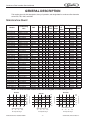
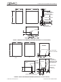
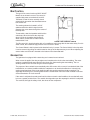
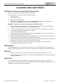
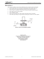
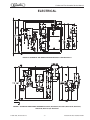
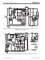
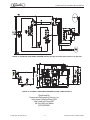
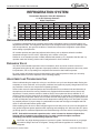
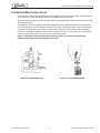
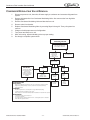
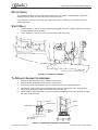
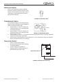
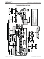
®
CONTINUOUS FLOW ICEMAKER
500, 700, 1000, 2000 - Series
Service Manual
Distributed By:
Commercial Refrigeration Service, Inc.
http://www.CorneliusParts.COM
http://www.IceCubes.NET
toll free (866) Ice Maker
(623) 869-8881
Release Date: May 27, 2004
Publication Number: 630460174SER
Revision Date: September 24, 2008
Revision: D
Visit the IMI Cornelius web site at www.cornelius.com for all your Literature needs.
CONTINUOUS FLOW ICEMAKER
SERVICE MANUAL
The products, technical information, and instructions contained in this manual are subject
to change without notice. These instructions are not intended to cover all details or variations of the equipment, nor to provide for every possible contingency in the installation,
operation or maintenance of this equipment. This manual assumes that the person(s)
working on the equipment have been trained and are skilled in working with electrical,
plumbing, pneumatic, and mechanical equipment. It is assumed that appropriate safety
precautions are taken and that all local safety and construction requirements are being
met, in addition to the information contained in this manual.
To inquire about current revisions of this and other documentation or for assistance with
any Cornelius product contact:
www.cornelius.com
800-238-3600
Trademarks and copyrights:
Aurora, Cornelius, Decade, Hydro Boost, Sitco, Spirit, UF-1, Vanguard, Venture, Olympus, and Vista are registered trademarks of IMI Cornelius Inc.
Optifill trademark is pending.
This document contains proprietary information and it may not be
reproduced in any way without permission from Cornelius.
Printed in U.S.A.
Copyright © 2004-2008, All Rights Reserved, IMI Cornelius, Inc.
Distributed By:
Commercial Refrigeration Service, Inc.
http://www.CorneliusParts.COM
http://www.IceCubes.NET
toll free (866) Ice Maker
(623) 869-8881
Continuous Flow Icemaker Service Manual
Safety . . . . . . . . . . . . . . . . . . . . . . . . . . . . . . . . . . . . . . . . . . . . . . . . . . . . . . . . . . . . . . . .1
Safety Instructions . . . . . . . . . . . . . . . . . . . . . . . . . . . . . . . . . . . . . . . . . . . . . . . . . . .1
Read and Follow all Safety Instructions . . . . . . . . . . . . . . . . . . . . . . . . . . . . . . . .1
Recognize Safety Alerts . . . . . . . . . . . . . . . . . . . . . . . . . . . . . . . . . . . . . . . . . . . .1
Different Types of Alerts . . . . . . . . . . . . . . . . . . . . . . . . . . . . . . . . . . . . . . . . . . . .1
Safety Tips . . . . . . . . . . . . . . . . . . . . . . . . . . . . . . . . . . . . . . . . . . . . . . . . . . . . . . . . .1
Qualified Service Personnel . . . . . . . . . . . . . . . . . . . . . . . . . . . . . . . . . . . . . . . . . . . .1
Shipping And Storage . . . . . . . . . . . . . . . . . . . . . . . . . . . . . . . . . . . . . . . . . . . . . . . . .1
General Description . . . . . . . . . . . . . . . . . . . . . . . . . . . . . . . . . . . . . . . . . . . . . . . . . . . .2
Specification Chart . . . . . . . . . . . . . . . . . . . . . . . . . . . . . . . . . . . . . . . . . . . . . . . . . . .2
Bin Control . . . . . . . . . . . . . . . . . . . . . . . . . . . . . . . . . . . . . . . . . . . . . . . . . . . . . . . . .5
Gearmotor . . . . . . . . . . . . . . . . . . . . . . . . . . . . . . . . . . . . . . . . . . . . . . . . . . . . . . . . . .5
Cleaning and Sanitizing . . . . . . . . . . . . . . . . . . . . . . . . . . . . . . . . . . . . . . . . . . . . . . . . .6
Icemaker Cleaning and Sanitizing Procedures . . . . . . . . . . . . . . . . . . . . . . . . . . . . . .6
Maintenance . . . . . . . . . . . . . . . . . . . . . . . . . . . . . . . . . . . . . . . . . . . . . . . . . . . . . . . .6
Monthly . . . . . . . . . . . . . . . . . . . . . . . . . . . . . . . . . . . . . . . . . . . . . . . . . . . . . . . . . . . .6
Quarterly . . . . . . . . . . . . . . . . . . . . . . . . . . . . . . . . . . . . . . . . . . . . . . . . . . . . . . . . . . .6
Semi-annually . . . . . . . . . . . . . . . . . . . . . . . . . . . . . . . . . . . . . . . . . . . . . . . . . . . . . . .7
Water Level Control . . . . . . . . . . . . . . . . . . . . . . . . . . . . . . . . . . . . . . . . . . . . . . . . . . . .8
How Water Level Control Works . . . . . . . . . . . . . . . . . . . . . . . . . . . . . . . . . . . . . . . . .8
Purpose . . . . . . . . . . . . . . . . . . . . . . . . . . . . . . . . . . . . . . . . . . . . . . . . . . . . . . . . . . . .8
To Replace Water Level Control . . . . . . . . . . . . . . . . . . . . . . . . . . . . . . . . . . . . . . . . .8
To Replace Water Level Safety Switch . . . . . . . . . . . . . . . . . . . . . . . . . . . . . . . . . . . .8
Electrical . . . . . . . . . . . . . . . . . . . . . . . . . . . . . . . . . . . . . . . . . . . . . . . . . . . . . . . . . . . . .9
Refrigeration System . . . . . . . . . . . . . . . . . . . . . . . . . . . . . . . . . . . . . . . . . . . . . . . . . .12
Refrigeration System Adjustments . . . . . . . . . . . . . . . . . . . . . . . . . . . . . . . . . . . . . .12
Expansion Valve . . . . . . . . . . . . . . . . . . . . . . . . . . . . . . . . . . . . . . . . . . . . . . . . . . . .12
Adjustment and Troubleshooting . . . . . . . . . . . . . . . . . . . . . . . . . . . . . . . . . . . . . . .12
Condenser Modulating Valve . . . . . . . . . . . . . . . . . . . . . . . . . . . . . . . . . . . . . . . . . .13
Condenser Modulating Valve Removal . . . . . . . . . . . . . . . . . . . . . . . . . . . . . . . . . . .14
Motor Check . . . . . . . . . . . . . . . . . . . . . . . . . . . . . . . . . . . . . . . . . . . . . . . . . . . . . . .15
Start Relay . . . . . . . . . . . . . . . . . . . . . . . . . . . . . . . . . . . . . . . . . . . . . . . . . . . . . . . .15
To Replace Gearmotor Assembly . . . . . . . . . . . . . . . . . . . . . . . . . . . . . . . . . . . . . . .15
Installation and Shaft Seal Replacement 500 . . . . . . . . . . . . . . . . . . . . . . . . . . . . . .16
Auger and Extruding Head Removal . . . . . . . . . . . . . . . . . . . . . . . . . . . . . . . . . . . .16
Installation and Shaft Seal Replacement 700 & 1000 . . . . . . . . . . . . . . . . . . . . . . . .17
Upper Nut and Bearing Assembly . . . . . . . . . . . . . . . . . . . . . . . . . . . . . . . . . . . . . . .17
To Replace Bearing . . . . . . . . . . . . . . . . . . . . . . . . . . . . . . . . . . . . . . . . . . . . . .17
Electrical Checkout . . . . . . . . . . . . . . . . . . . . . . . . . . . . . . . . . . . . . . . . . . . . . . . . . .17
Overload Check . . . . . . . . . . . . . . . . . . . . . . . . . . . . . . . . . . . . . . . . . . . . . . . . . . . .18
Compressor Check . . . . . . . . . . . . . . . . . . . . . . . . . . . . . . . . . . . . . . . . . . . . . . . . . .18
Capacitor Check . . . . . . . . . . . . . . . . . . . . . . . . . . . . . . . . . . . . . . . . . . . . . . . . . . . .18
Safety Controls . . . . . . . . . . . . . . . . . . . . . . . . . . . . . . . . . . . . . . . . . . . . . . . . . . . . .19
Troubleshooting . . . . . . . . . . . . . . . . . . . . . . . . . . . . . . . . . . . . . . . . . . . . . . . . . . . . . .21
© 2004-2005, IMI Cornelius Inc.
-i-
Publication Number: 630460174SER
Continuous Flow Icemaker Service Manual
Publication Number: 630460174SER
- ii -
© 2004-2005, IMI Cornelius Inc.
Continuous Flow Icemaker Service Manual
SAFETY
SAFETY INSTRUCTIONS
Read and Follow all Safety Instructions
Read and follow all safety instructions in this manual and on the machine (decals, labels, and laminated
cards).
Read and understand all applicable OSHA (Occupation Safety and Health Administration) safety regulations before operating the machine.
Recognize Safety Alerts
This is the safety alert symbol. When you see it in this manual or on the machine be
alert to the potential of personal injury or damage to the machine.
Different Types of Alerts
There are 3 types of safety alerts:
DANGER — Indicates an immediate hazardous situation which if not avoided WILL result in serious injury, death, or equipment damage.
WARNING — Indicates a potentially hazardous situation which, if not avoided, COULD result in
serious injury, death, or equipment damage.
CAUTION — Indicates a potentially hazardous situation which, if not avoided, MAY result in
minor or moderate injury or equipment damage.
SAFETY TIPS
• Carefully read all safety messages in this manual and safety signs on the machine.
• Keep safety signs in good condition and replace missing or damaged safety signs.
• Learn how to operate the machine and how to use the controls properly.
• Do not let anyone operate the machine without proper training. This appliance is not intended for use
by very young children or infirm persons without supervision. Young children should be supervised to
ensure that they do not play with the appliance.
• Keep your machine in proper working condition and do not allow unauthorized modifications to the
machine.
QUALIFIED SERVICE PERSONNEL
CAUTION — Only trained and certified electrical, plumbing and refrigeration technicians should
service this unit. ALL WIRING AND PLUMBING MUST CONFORM TO NATIONAL AND LOCAL
CODES.
SHIPPING AND STORAGE
CAUTION — Before shipping, storing, or relocating the Unit, syrup systems must be sanitized
and all sanitizing solution must be purged from the syrup systems. All liquids, after sanitizing, must
be purged from the unit. A freezing ambient environment will cause residual sanitizing solution or
water remaining inside the Unit to freeze resulting in damage to the internal components.
© 2004-2005, IMI Cornelius Inc.
-1-
Publication Number: 630460174SER
Continuous Flow Icemaker Service Manual
GENERAL DESCRIPTION
This section gives the Unit description, theory of operation, and design data for continuous flow icemaker
series 500, 700, 1000, and 2000.
SPECIFICATION CHART
Models
Condensing
Unit
VAC
HZ
WCC500-A
WCC500-W
WCC502-A
WCC502-W
WCF510-A
WCF510-W
WCF512-A
WCF512-W
WCC700-A
WCC700-W
WCC701-A
WCC701-W
WCC702-A
WCC702-W
WCF710-A
WCF710-W
WCC711-A
WCC711-W
WCF712-A
WCF712-W
WCC1001-A
WCC1001-W
WCC1002-A
WCF1101-A
WCF1101-W
WCF1102-A
WCC1001-R
WCF1101-R
WCC2001–A
WCC2001–R
WCC2001–W
WCC2002–A
WCF2201–A
WCF2201–W
WCF2202–A
Air Cooled
Water Cooled
Air Cooled
Water Cooled
Air Cooled
Water Cooled
Air Cooled
Water Cooled
Air Cooled
Water Cooled
Air Cooled
Water Cooled
Air Cooled
Water Cooled
Air Cooled
Water Cooled
Air Cooled
Water Cooled
Air Cooled
Water Cooled
Air Cooled
Water Cooled
Air Cooled
Air Cooled
Water Cooled
Air Cooled
Remote
Remote
Air–Cooled
Remote
Water Cooled
Air Cooled
Air–Cooled
Water Cooled
Air Cooled
115
115
220/240
220/240
115
115
220/240
220/240
115
115
208/230
208/230
220/240
220/240
115
115
208/230
208/230
220/240
220/240
208/230
208/230
220/240
208/230
208/230
220/240
220/240
208/230
208/230
208/230
208/230
220/240
208/230
208/230
220/240
60
60
50
50
60
60
50
50
60
60
60
60
50
50
60
60
60
60
50
50
60
60
50
60
60
50
60
60
60
60
60
50
60
60
50
PH Wire
1
1
1
1
1
1
1
1
1
1
1
1
1
1
1
1
1
1
1
1
1
1
1
1
1
1
1
1
1
1
1
1
1
1
1
2
2
2
2
2
2
2
2
2
2
2
2
2
2
2
2
2
2
2
2
2
2
2
2
2
2
2
2
2
2
2
2
2
2
2
Comp. Fan
RLA Amps
10.1
10.1
5.3
5.3
10.1
10.1
5.3
5.3
12
12
7.7
7.7
8.2
8.2
12
12
7.7
7.7
8.2
8.2
7.5
7.5
8.9
7.5
7.5
8.9
7.5
7.5
12.9
12.9
12.9
11.4
12.9
12.9
11.4
1.1
N/A
0.5
N/A
1.1
N/A
0.5
N/A
1.6
N/A
1.6
N/A
0.5
N/A
1.6
N/A
1.6
N/A
0.5
N/A
0.85
N/A
0.85
0.85
N/A
0.85
N/A
N/A
.85
1.7
N/A
.85
.85
N/A
.85
GRMT
R
Amps
2
2
1.6
1.6
2
2
1.6
1.6
2
2
2
2
1.6
1.6
2
2
2
2
1.6
1.6
2
2
2
2
2
2
2
2
(2) 2
(2) 2
(2) 2
(2) 2
(2) 2
(2) 2
(2) 2
Refrigerant
Oz.
Type
24
11
24
11
24
11
24
11
24
13
24
13
24
13
24
13
24
13
24
13
26
17
26
26
17
26
120
120
46
220
28
46
46
28
46
R404A
R404A
R404A
R404A
R404A
R404A
R404A
R404A
R404A
R404A
R404A
R404A
R404A
R404A
R404A
R404A
R404A
R404A
R404A
R404A
R404A
R404A
R404A
R404A
R404A
R404A
R404A
R404A
R404A
R404A
R404A
R404A
R404A
R404A
R404A
Circuit
Fuse
20
20
20
20
20
20
20
20
20
20
20
20
20
20
20
20
20
20
20
20
20
20
20
20
20
20
15
15
25
25
25
25
25
25
25
NOTE: For units not listed in above chart, refer to nameplate or contact factory service.
80
70
60
–70
–90
–100
Publication Number: 630460174SER
600
1000
450
400
Capacity Lbs./24 hr.
1100
500
900
800
700
600
350
90
Air Temperature Deg. F
650
550
50
Water Temperature Deg. F
–50
Capacity Lbs./24 hr.
340
320
300
280
260
240
90
WCC1000
WCC700
400
380
360
Capacity Lbs./24 hr.
WCC500
80
70
60
50
Water Temperature Deg. F
–50
–70
–90
–100
Air Temperature Deg. F
-2-
90
80
70
60
50
Water Temperature Deg. F
–50
–70
–90
–100
Air Temperature Deg. F
© 2004-2005, IMI Cornelius Inc.
Continuous Flow Icemaker Service Manual
25.00
14.50
1.38
1.75
INLET 3/8 FLARED
WATER COOLED ONLY
OUTLET 3/8 FLRE
WATER COOLED ONLY
24.50
DRAIN 3/8 ID TYGON TUBE
10.15
WATER IN 1/4 FLARE
ELECTRIC 7/8 DIA
1.50
1.81
FRONT
2.12
2.50
SIDE
1.19
BACK VIEW
AIR OR WATER COOLED
FRONT
ICE DISCHARGE
3.50
FIGURE 1. SERIES 500 & 700 DIMENSION DRAWING (SHIPPING WT. 160 LBS. APPROX).
24.00
22.00
BACK VIEW
(AIR COOLED)
27.00
ELECTRICAL 7/8” DIA.
WATER UB 1/4” MALE FLARE
DRAIN 3/8” ID TYGON TUBE
2.25
2.25
0.94
13.94
SIDE
FRONT
(REMOTE)
DISCHARGE LINE
1/2 PUNCTURE FITTING
W/C INLET
3/8” FPT
FRONT
AIR EXHAUST
W/C OUTLET 3/8” FPT OR
REMOTE COND. LIQ. LINE
3/8 PUCTURE FITTING
POWER INLET
ICE DISCHARGE 7/8” DIA.
DRAIN 3/8” ID TUBE
WATER INLET
1/4” MALE FLARE
9.04
4.50
2.19
1.00
5.87
2.06
2.50
1.88
9.00
BOTTOM VIEW
(VIEWED FROM BOTTOM OF MACHINE)
10.44
FIGURE 2. SERIES 1000 DIMENSION DRAWING (SHIPPING WT. 210 LBS. APPROX).
© 2004-2005, IMI Cornelius Inc.
-3-
Publication Number: 630460174SER
Continuous Flow Icemaker Service Manual
18.13
30.00
WATER IN
ELECTRICAL 7/8 DIA.
28.06
23.50
AIR INLET
DRAIN 3/8 I.D. TUBE
2.25
BACK
FRONT
2.06
24.00
ICE DISCHARGE
9.50
2.06
20.13
3.81
FRONT
2.06
SIDE
BOTTOM
VIEWED FROM BOTTOM OF MACHINE
FIGURE 3. SERIES WCC2001-A AND WCF2201-A DIMENSION DRAWINGS
Publication Number: 630460174SER
-4-
© 2004-2005, IMI Cornelius Inc.
Continuous Flow Icemaker Service Manual
BIN CONTROL
The type of bin control used on all WCC & WCF
Models is an electronic control. The control is
supplied with power to terminals X1 and X2.
Terminals X3 and X4 are a normally closed
switch which open when the thermostat sensor
bulb senses ice.
The sensing element is located in a 5/16”
stainless steel tube which hangs from the
dispense tray cover down through the center of
the drop tube.
To test switch, start the icemaker and block the
outlet tube. When the ice fills the drop tube
about 1/2 full the icemaker should shut off.
When tube is cleared the ice maker should
restart within 5 min.
BIN CONTROL
SWITCH TERMINALS
FIGURE 4. BIN CONTROL SWITCH
The Bin control is in electrical series with coil on antifreeze relay along with the low water safety. If unit is
water cooled, the condenser high pressure cut out is also in series.
The Control Switch is held in place inside electrical box by 2 screws. The Control bulb is in the drop tube.
It can be removed by pulling the cable located on the top of the dispense tray cover. When replacing the
sensor make sure the bulb is inserted to the bottom of the thermostat well.
GEARMOTOR
The gearmotor is equipped with a start relay and a manual reset overload.
When current is applied, the relay energizes and completes the circuit to the start winding. The motor
reaches a predetermined speed and the relay drops out, disconnecting the start winding. The run
winding remains in the circuit as long as current is applied.
The purpose of the overload is to automatically shut off the motor in the event of a mechanical bind of the
transmission, an overload condition within the evaporator or an electrical malfunction. It does this by
sensing amperage draw. If the motor stalls the start relay would energize and stay energized. The
amperage would surge 5 to 6 times greater than the normal draw. In this event the overload would shut
off the transmission in 4 to 8 seconds.
If the motor is subjected to an abnormal load, but does not reach a stall condition, the overload will react,
but over a greater period of time. The reaction time depends upon the amperage to which it is subjected.
The overload, through the safety circuit, also shuts off the compressor.
© 2004-2005, IMI Cornelius Inc.
-5-
Publication Number: 630460174SER
Continuous Flow Icemaker Service Manual
CLEANING AND SANITIZING
ICEMAKER CLEANING AND SANITIZING PROCEDURES
Do not use any of the ice made during cleaning operations.
Clean and sanitize ice storage area when cleaning icemaker.
1.
2.
3.
4.
Turn machine off.
Shut off water supply.
Remove ice from storage bin.
Mix approved cleaner (2 gallons as directed). Recommended cleaner: Nu-Calgon liquid ice
machine cleaner. Mixture: 3-1/3 ounces per gallon of water.
WARNING: Cleaner must be safe for stainless steel. NO EXCEPTIONS!
5.
Clean auger/diverter assembly and ice transition/drop tube in a sink using cleaner mixture and
reinstall in icemaker. Using cleaner, wipe down the dispense tray.
6.
Turn machine on and add cleaner solution to water level control until 2 gallons have been used.
7.
Turn on water supply and run machine for 15 minutes.
8.
Turn off machine and remove all ice.
9.
Sanitize using household liquid bleach (50 ppm chlorine). Mixture: 1 fluid ounce per gallon room
temperature water. 2 minute exposure time.
10. Sanitize auger/diverter assembly and ice transition/drop tube in a sink using sanitizing solution and
reinstall in icemaker. Using sanitizer, wipe down the dispense tray.
11. Fill icemaker with sanitizer by slowly pouring solution into water feed reservoir until full. Solution will
drain through overflow tube. Do not run machine. Allow to air dry.
12. If icemaker is used in conjunction with ice dispenser or storage bin, follow manufacturer’s
recommended cleaning instructions at this time.
MAINTENANCE
Preventive maintenance can increase the trouble free life of your icemaker. Many authorized service
agencies offer service contracts for your icemaker. Contact your local distributor for further information.
MONTHLY
1.
2.
Clean the condenser. Use a brush, vacuum cleaner or blow from inside with air or CO2 gas.
Inspect water feed reservoir at lease once a month until a definite pattern for cleaning and sanitizing
has been established.
QUARTERLY
This is the maximum period of time between cleaning and sanitizing the icemaker. In addition to
recommended monthly procedure, and if a more frequent cleaning and sanitizing pattern has not been
established, unit must be cleaned and sanitized.
Publication Number: 630460174SER
-6-
© 2004-2005, IMI Cornelius Inc.
Continuous Flow Icemaker Service Manual
SEMI-ANNUALLY
Semi–Annually in addition to all previously established service procedures perform the following:
1.
2.
3.
4.
5.
6.
7.
Check for water leaks in tube connections, water fittings and lower icemaker water seal.
Check drain tubes for clogs and aged tubes. Replace if tubes are stained or brittle.
Check for signs of condensation. Clean where necessary and replace insulation properly.
Check safety circuits for proper operation.
Check refrigeration system.
Check unit for abnormal noise. Tighten machine and cabinet screws, if necessary.
Check white upper bearings on auger assembly. If bearings are less than 1/16” thick, replace.
REPLACE
OK
1/16
1/16
OK
REPLACE
FIGURE 5. UPPER NUT AND BEARING ASSEMBLY
Distributed By:
Commercial Refrigeration Service, Inc.
http://www.CorneliusParts.COM
http://www.IceCubes.NET
toll free (866) Ice Maker
(623) 869-8881
© 2004-2005, IMI Cornelius Inc.
-7-
Publication Number: 630460174SER
Continuous Flow Icemaker Service Manual
WATER LEVEL CONTROL
HOW WATER LEVEL CONTROL WORKS
When water is introduced through the inlet fitting the float rises. the float pushes against a lever which in
turn forces the poppet assembly against the inlet fitting valve seat which seals the water off. Before the
water inlet is sealed the safety switch is operated. In the event of a water failure the float would drop down
and operate the safety switch to shut off the machine.
If water level control will not shut off and seal at level as indicated, be sure inlet pressure does not exceed
recommended factory operating range.
Under ordinary circumstances adjustment should not be necessary providing it was properly adjusted
when unit was installed or relocated. If, however, the control becomes inoperative, repair or replace. See
Start–Up Adjustment in the Installation Manual.
PURPOSE
1.
2.
3.
To automatically maintain proper water level in the evaporator when unit is running and making ice.
A safety switch is operated in the event of an interruption in water supply. The switch shuts off the
electrical power to the icemaker and its refrigeration system. Switch will reset as soon as cause of
water failure has been corrected and proper water level in icemaker has again been reached.
The transparent bowl not only provides a visible check of water level, but also is a good guide to the
internal conditions which exist within the icemaker assembly itself. (See Cleaning Procedure.)
TO REPLACE WATER LEVEL CONTROL
1.
2.
3.
4.
5.
Shut off the water supply. Shut off the main power switch or unplug the ice dispenser from electrical
outlet.
Remove the flexible tubing from bottom of water level control and drain water from water level
control and evaporator.
Remove flexible tubing at bottom of water level bowl connected to the overflow.
Hold water inlet fitting with proper tool to prevent it from rotating when disconnecting the water inlet.
Remove wing nut holding water control to its mounting bracket. Control can be removed by lifting
straight up.
TO REPLACE WATER LEVEL SAFETY SWITCH
1.
2.
3.
Shut off main power switch or unplug the ice dispenser from electrical outlet.
Unplug molex connector connecting switch to electrical box.
Remove the 2 screws anchoring the water level safety switch to the bottom of the water level control
mounting bracket.
Publication Number: 630460174SER
-8-
© 2004-2005, IMI Cornelius Inc.
Continuous Flow Icemaker Service Manual
ELECTRICAL
FIGURE 6. SCHEMATIC AND WIRING DIAGRAM WCC2001-A AND WCF2201-A
FIGURE 7. SCHEMATIC AND WIRING DIAGRAM WCC500-A, WCC500-W, WCC700-A, WCC700-W, WCF510-A,
WCF510-W, WCF710-A, & WCF710-W
© 2004-2005, IMI Cornelius Inc.
-9-
Publication Number: 630460174SER
Continuous Flow Icemaker Service Manual
FIGURE 8. SCHEMATIC AND WIRING DIAGRAM WCC701-A, WCC701-W, WCC1001-A, WCC1001-W, WCF711-A,
WCF711-W, WCF1101-A, & WCF1101-W
FIGURE 9. SCHEMATIC AND WIRING DIAGRAM WCF1101R, WCC1001R, WCF1102R, & WCC1102R
Publication Number: 630460174SER
- 10 -
© 2004-2005, IMI Cornelius Inc.
Continuous Flow Icemaker Service Manual
FIGURE 10. SCHEMATIC AND WIRING DIAGRAM WCC502, WCC702, WCC1002, WCF512, WCF712, & WCF1102
FIGURE 11. SCHEMATIC AND WIRING DIAGRAM WCC2001-R AND WCF2201-R
Distributed By:
Commercial Refrigeration Service, Inc.
http://www.CorneliusParts.COM
http://www.IceCubes.NET
toll free (866) Ice Maker
(623) 869-8881
© 2004-2005, IMI Cornelius Inc.
- 11 -
Publication Number: 630460174SER
Continuous Flow Icemaker Service Manual
Air Temperature
REFRIGERATION SYSTEM
50°
60°
70°
80°
90°
100°
40°
162
188
214
245
275
309
Thermostatic Expansion Valve NO Adjustment.
+/- 10 lbs. Discharge Pressure
Water Temperature
WCC 500
WCC 700
WCC 1000
65°
90°
50°
65°
90°
50°
65°
166
168
60°
177
180
60°
171
‘92
194
70°
205
208
70°
199
218
220
80°
233
236
80°
227
249
251
90°
269
272
90°
263
279
281
100°
304
307
100°
298
313
315
328
334
340
324
328
90°
172
200
228
264
299
332
50°
60°
70°
80°
90°
100°
362
WCC 2200
65°
201
219
253
298
330
364
90°
203
220
254
300
332
366
REFRIGERATION SYSTEM ADJUSTMENTS
A complete understanding of the icemaker and hermetic refrigeration system is necessary before any
adjustments are made. The refrigeration technician must use high and low side pressure readings, water
and air temperatures, plus general conditions of cleanliness to assess the refrigeration system status
when making any adjustments.
All icemaker products are tested and adjusted at the factory prior to shipment where the ambient
temperature ranges from 65° to 90°F, depending on the season of the year.
Whenever a new icemaker product is initially installed and started–up, it is imperative that the start–up
operation make the following checks and/or readjustments for local conditions.
EXPANSION VALVE
You will find a thermostatic expansion valve on icemakers, which is used to control the amount of
refrigerant flowing through the evaporator. Improperly installed or defective expansion valves may cause
low production, soft ice, squeaking from evaporator and excessive load inside evaporator.
By using general refrigeration system troubleshooting along with the pressure charts you can easily
determine whether or not the expansion valve is working properly.
ADJUSTMENT AND TROUBLESHOOTING
When troubleshooting the expansion valve you must first be sure you have adequate water flowing into
evaporator, a clean condenser, unit is properly ventilated, and system is properly charged and free from
any restrictions. Also be sure compressor is operating properly.
Second, take reservoir water temperature and air temperature from condenser inlet and determine at
what pressure unit should be running. Machines are equipped with thermostatic valves, there is NO
adjustment. If correct pressure cannot be obtained, first be sure system has time to stabilize 10–15
minutes. Second, be sure sensing bulb is located at 12:00 position on outlet side of evaporator about 3–4
inches away from evaporator and be sure to insulate well and clamp tightly to tubing. If system pressures
are still not adequate, take a second water and air temperature reading and go over other parts of system
for possible problems. If proper charge is questionable evacuate and recharge to nameplate and leak
check. If valve still malfunctions replace valve.
When replacing valve be sure to bleed refrigerant gas from low side port so as not to lose refrigerant oil.
Use general refrigerant system practices when replacing and recharging unit. After new valve is in place,
go through previous monitored adjustments and troubleshooting to be sure valve is functioning properly.
NOTE: Units with thermostatic expansion valve—valve is located on bottom refrigerant line.
Sensing bulb is located on top refrigerant line. On water cooled units adjust condenser
modulating valve before troubleshooting expansion valve.
CAUTION: Very High discharge pressure is present in system. Quick disconnects on you gauges
will minimize danger and loss of refrigerant. Comply with federal regulations for reclaiming
refrigerant.
Publication Number: 630460174SER
- 12 -
© 2004-2005, IMI Cornelius Inc.
Continuous Flow Icemaker Service Manual
CONDENSER MODULATING VALVE
The reason for using a water modulating valve is to supply the correct amount of water to the condenser.
and to maintain a proper operating pressure to refrigeration system high side.
The flow of water through the valve is increased as the high side pressure rises and is decreased as high
side pressure lowers.
To calibrate the amount of water flow with the refrigeration system high side pressure, turn adjustment
screw located on end of valve opposite of bellows. Turn screw counterclockwise to raise opening point or
clockwise to lower opening point. Opening point of valve should be set to maintain proper operating
pressure in refrigeration system high side. Refer to Pressure Chart on. Closing point of valve should be
set low enough to close valve during compressor stand–by periods.
NOTE: Cold water will absorb heat faster than warm water. The water flow will therefore
automatically increase as inlet temperature increases.
SIGHT
GLASS
THERMOSTATIC
EXPANSION VALVE
FIGURE 12. EXPANSION VALVE
© 2004-2005, IMI Cornelius Inc.
FIGURE 13. ADJUSTMENT SCREW
- 13 -
Publication Number: 630460174SER
Continuous Flow Icemaker Service Manual
CONDENSER MODULATING VALVE REMOVAL
1.
2.
3.
4.
5.
6.
7.
8.
9.
Disconnect power to unit, then shut off water supply to condenser and evacuate refrigerant from
system.
Remove inlet water line from Condenser Modulating Valve. Also remove tube from high side
refrigerant line.
Remove Condenser Modulating Valve and bracket from unit.
Remove valve from bracket.
Replace Condenser Modulating Valve by reversing Steps 2 through 4. Then pull system into
vacuum.
Charge unit with proper amount of refrigeration.
Turn power and water on to unit.
With unit running, adjust modulating valve to proper setting.
Go through a complete system check.
GEARMOTOR
OVERLOAD TRIPPED
Check water level control
and evaporator water tube
for line build-up restrictions.
NO
YES
CAUTION
Clear ice from
evaporator and
auger before
resetting overload.
CLEAN
See Instructions.
Reset overload.
IMPORTANT
Icemaker runs when
reset but problem has
not been found.
Continue checking for
overload as follows to
guard against future
problems.
Icemaker
runs.
Short run. Trips
again in 2
minutes. Check
gearmotor circuits.
Resets but
motor does
not run.
Resets but
motor does
not run.
Check
gearmotor
circuits.
OVERLOAD GUIDE
ELECTRICAL:
Will not
Reset.
Overload
hot try
again.
Will not
reset.
Replace
overload.
High or low voltage. Weak power lines can cause overloads on icemakers restarts.
High running current (2.4amps or above). Check motor circuits and start relay.
Auger delay failed.
ICEMAKER
Mechanical parts worn. Scored evaporator or auger. Worn thrust bearing.
Icemaker not turning off. Failed ice level control.
Over compression. Low water inlet temperature. Restrictions in water line from reservoir.
REFRIGERANT
Contaminated charge or bad compressor.
Low charge or gas leak.
Low suction pressure. Improper expansion valve. Sensing bulb location or insulation
and/or defective expansion valve.
Publication Number: 630460174SER
- 14 -
© 2004-2005, IMI Cornelius Inc.
Continuous Flow Icemaker Service Manual
MOTOR CHECK
The resistance readings on the winding will be between 5 to 25 ohms. A meter capable of these low
readings must be used. The start relay cover must be removed.
If no continuity on start or run winding test, replace gearmotor. If continuity on grounded motor test,
replace gearmotor.
START RELAY
1.
2.
Check between “2” and “4” on relay (with relay unplugged). If there is continuity replace the relay, as
the relay contacts should be open.
Check between “3” and “4” on relay, if no continuity replace the relay.
FIGURE 14. GEARMOTOR ASSEMBLY
TO REPLACE GEARMOTOR ASSEMBLY
1.
2.
3.
4.
5.
Disconnect the icemaker from the electrical power source.
Disconnect the transmission cable from the electrical box.
Remove the 4 hex head bolts securing the evaporator to the top of the transmission.
Remove the 4 bolt’s holding the transmission and bracket to frame base, while supporting the
weight of the evaporator. Remove the transmission from the unit.
When replacing the transmission, it may be necessary to rotate the auger back and forth to align
the motor shaft and auger.
AUGER NUT
AUGER
BEARING NYLON
BEARING DELRIN
“D” DRIVE
GROOVE
EXTRUDING
HEAD
ANTI–ROTATION
RIB – 3 PLACES
FIGURE 15. AUGER AND EXTRUDING HEAD REMOVAL
© 2004-2005, IMI Cornelius Inc.
- 15 -
Publication Number: 630460174SER
Continuous Flow Icemaker Service Manual
INSTALLATION AND SHAFT SEAL REPLACEMENT 500
1.
2.
3.
4.
Place shaft seal locator seat over gear
motor output shaft, embossed side down,
and push down until shaft seal seat rests
flush on top of gear motor.
Place rubber coated ceramic seal
(important: ceramic face up) over output
shaft and push down until seal rests on top
of the shaft seal seat. (Lubricate rubber on
ceramic seal with rubber lubricant.)
Place shaft seal with carbon face down
(spring up) over output shaft and push
(gently) downward until seal rests on
ceramic face of the output shaft seal.
Place flat washer over output shaft and let
rest on the output shaft seal. Push down
on the washer compressing the spring on
the output shaft seal. While holding the
seals (down) in place slide the E–ring into
the groove on the output shaft.
E–RING
WASHER, PLAIN FLAT
SHAFT SEAL
LOCATOR SEAL
GEARMOTOR
FIGURE 16. SHAFT SEAL 500
AUGER AND EXTRUDING HEAD REMOVAL
1.
2.
3.
4.
5.
Disconnect unit from power supply.
Remove storage container cover and put aside.
Turn off water supply to icemaker.
After ice has melted from head take hold of the auger nut and lift straight up to disengage from
icemaker.
When replacing the auger assembly, make certain that both the auger engages the output shaft
drive and the extruding head ribs engage the evaporator tube.
Distributed By:
Commercial Refrigeration Service, Inc.
http://www.CorneliusParts.COM
http://www.IceCubes.NET
toll free (866) Ice Maker
(623) 869-8881
Publication Number: 630460174SER
- 16 -
© 2004-2005, IMI Cornelius Inc.
Continuous Flow Icemaker Service Manual
INSTALLATION AND SHAFT SEAL REPLACEMENT 700 & 1000
1.
2.
3.
4.
Place shaft seal locator seat and shaft
seal mount over gearmotor output shaft
and push down until shaft seal seat and
shaft seal mount rest flush on top of
gearmotor.
Place rubber coated ceramic seal
(important: ceramic face up) over output
shaft and push down until seal nest in
recess of shaft seal mount. (lubricate
rubber on ceramic seal with rubber
lubricant).
Place shaft seal with carbon face down
(spring up) over output shaft and push
(gently) downward until seal rests on
carbon face of the output shaft seal.
Place flat washer over output shaft and let
rest on the output shaft seal. Push down
on the washer compressing the spring on
the output shaft seal. While holding the
seals (down) in place slide the E–ring into
the groove on the output shaft
E–RING
WASHER, PLAIN FLAT
SHAFT SEAL
MOUNT, SHAFT
SEAL
SEAT, SHAFT SEAL
GEARMOTOR
FIGURE 17. SHAFT SEAL 700 AND 1000
UPPER NUT AND BEARING ASSEMBLY
The upper white bearing located on top of the auger is used to absorb the force between the auger and
extruding head.
NOTE: The bearings are 3/32 thick. When they wear below 1/16 they should be replaced. Bearings
to be inspected for wear during quarterly maintenance.
To Replace Bearing
1.
2.
3.
4.
Disconnect unit from electric power.
Remove top panels.
Remove Dispense Tray Cover.
Use an open end wrench on auger nut connected to bearing and turn counterclockwise to remove
assembly.
5.
Remove worn bearings. Replace with new bearings and then reinstall assembly.
NOTE: If auger turns with nut, remove cover on top of gearmotor stator and hold motor while
loosening nut.
ELECTRICAL CHECKOUT
1.
2.
3.
Be sure the unit is disconnected from the power source. Remove the compressor electrical box
cover. Check for obvious damage and loose wires.
Disconnect the fan motor leads. Since capacitors store energy, short the capacitor with a
screwdriver. This will prevent shocks.
Disconnect the compressor terminal wires.
© 2004-2005, IMI Cornelius Inc.
- 17 -
Publication Number: 630460174SER
Continuous Flow Icemaker Service Manual
OVERLOAD CHECK
Using a volt–ohmmeter check the continuity
across the overload, contact #1 and #3. If none,
wait for unit to cool down and try again. If still no
continuity, the overload protector is defective
and should be replaced.
FIGURE 18. OVERLOAD CHECK
COMPRESSOR CHECK
The resistance readings on the windings will be
between 0.25 to 10.00 ohms, a meter capable of
these low readings must be used.
1.
2.
3.
4.
Check between “C” and “R.” Replace the
compressor if there is no continuity as the
run windings are open.
Check between “C” and “S.” Replace the
compressor if there is no continuity as the
FIGURE 19. COMPRESSOR CHECK
start windings are open.
Check between “C” and “R” or “S” and the shell of the compressor. If there is continuity, replace the
compressor as the motor is grounded.
Check between screw terminal on the overload and “C” on the compressor. Check and repair the
lead or connections if there is no continuity.
CAPACITOR CHECK
1.
2.
Check or replace start capacitor,
disconnect bleed resistor before checking
for shorted capacitor.
Check or replace run capacitor (if
supplied) check for shorted capacitor or
either terminal grounded to case.
GEAR MOTOR OVERLAY
FIGURE 20. GEAR MOTOR OVERLOAD
Publication Number: 630460174SER
- 18 -
© 2004-2005, IMI Cornelius Inc.
Continuous Flow Icemaker Service Manual
SAFETY CONTROLS
Your icemaker unit has several safety and control devices incorporated into its design.
WARNING: None of the below described devices should ever be “bypassed” to allow the unit to
function.
The safety and control system shut–off devices are:
1.
2.
3.
4.
5.
6.
7.
Low water shut off reed switch located in icemaker float assembly. (Automatic reset type.)
Gearmotor thermal overload, manual reset type (red button on motor).
Compressor thermal overload, automatic reset type.
Anti–freeze relay and associated circuit. See wiring diagrams.
Main service switch located on top of the control box.
Bin Control.
High pressure cut out (water cooled only).
© 2004-2005, IMI Cornelius Inc.
- 19 -
Publication Number: 630460174SER
Continuous Flow Icemaker Service Manual
GUIDE TO GOOD ICE
CUSTOMER
COMMENTS
CHECK ICEMAKER
LOCATION CONDITIONS
FIRST
“It runs but the ice is
too soft.”
Proper air flow for condensing system.
“The icemaker is not
producing enough ice.”
Location too close to high
units such as coffee urns,
deep fryers, grills, etc.
“The ice is too wet.”
Supply water conditions
Water too warm
(above 90 o F).
Water artificially softened
above 262 ppm sodium chloride.
Normal water supply too high
in total dissolved solids
(above 500 PPM).
“It makes too much
noise.”
(With this comment
the ice is usually
extremely hard and
larger than normal.)
Check to see if noise
objection is normal fan and
air flow noise.
Over
Compression
Supply water conditions.
Water too cold (below
50 oF). (Possibly running
from pre-cooler.)
CHECK ICE MAKER
Use gauges for checking
suction and head
pressures. See manual
for correct reading and
conditions. Check frost
line and sight glass.
Check water level for
proper adjustment and
restrictions. See
Manual.
Check evaporator
assembly for worn
parts, bearings, scored
evaporator and auger,
bad expansion valve.
etc.
Check for loose parts
and screws rattling.
Check evaporator
assembly for worn
parts, bearings, scored
evaporator and auger,
bad expansion valve,
etc.
Obstructions partially
blocking ice exit from top of
evaporator.
Check fan and fan shroud.
Publication Number: 630460174SER
- 20 -
© 2004-2005, IMI Cornelius Inc.
© 2004-2005, IMI Cornelius Inc.
- 21 -
Open
valve
Evacuate and
recharge system.
Clean condenser.
Non-condensible
in system.
Condenser
fan not
running.
LAC not operating
properly (minimum
discharge pressure
180 lbs.).
Check for
leaks.
Replace LAC valve,
evacuate and
recharge system.
Remote condenser
units only
Replace
dryer.
Evacuate
and
recharge
system.
Plugged
liquid line
dryer.
Replace
valve.
Evacuate
and
recharge
system.
Check gears in
gearbox.
No
Check if
auger is
turning.
Icemaker
froze up.
Clean
and
tighten.
Replace
valve.
Plugged or
faulty TXV.
Bulb
loose.
TXV not
operating
properly.
High suction pressure
(30 lbs. or above).
IMPORTANT
Icemaker runs when reset
but problem has not been
found.
Continue checking for
overload as follows to
guard against future
problems
Clean all related
drain lines.
Yes
Check bin switch
Short run trips
again in 2 min
utes. Check gear
motor circuit.
Icemaker runs
Refer to guide
to Good Ice in
service manual.
No
ICEMAKER OPERATING BUT
SOFT ICE
Check
gearmotor
circuit.
Reset but
motor does
not run.
Reset
overload.
CAUTION
Clear ice from
evaporator and
auger before re
setting over
load.
No
Will not
reset
replace
overload
Overload
hot try
again.
Will not
reset.
CLEAN
see
instructions.
Yes
Check water level control
and evaporator water tube
for lime build up restriction.
GEARMOTOR OVERLOAD
TRIPPED
OVERLOAD GUIDE
ELECTRICAL
High or low voltage weak power lines can cause overloads on icemaker restarts
High running current. Check motor circuits and start relay - Auger delay failed.
ICEMAKER
Mechanical parts worn. Scored evaporator or auger. Worn thrust bearing.
Ice maker not turning off. Failed ice level control.
Over compression. Low water inlet temperature. Restriction in water line from
reservoir.
REFRIGERANT
Contaminated charge or bad compressor.
Low charge or gas leak.
Low suction pressure. Improper expansion valve sensing bulb. Location or insulation
and/or defective expansion valve
Replace valve
evacuate and
recharge.
TXV bulb
lost charge.
Check if extruding
head is down in
evaporator tube.
Clean and
insulate.
Bulb
uninsulated.
Suction line
not
insulated.
Low suction pressure
(20 lbs. or below).
Check that water is turned on.
Check for restriction in water line.
Check incoming water pressure
(minimum 10 lbs.).
Check water safety switch.
LOW WATER SAFETY
SWITCH OPEN
Valve
stuck
open.
Check drive on
gearmotor.
Check for
kinks or
damage to
liquid line.
Restricted
liquid line.
Condenser
dirty or
restricted.
Head
Pressure
high.
Evaporator water tube
may have an air bubble.
Clear air bubble from
tube.
Check line voltage.
Check compressor winding
& components.
Condenser fan running
but compressor not running
ICEMAKER RUNS BUT
DOES NOT MAKE ICE
Check electrical circuit
to fan motor.
Check fan motor.
Low on
refrigerant.
Too much
refrigerant in
system.
Check power
to condenser.
Remote condenser
not running.
Remote condenser
units only
Check electrical
wiring in control box
for loose connections.
Low pressure switch open
or cycling on and off.
Discharge
king valve
partially
closed.
High pressure
switch open or
cycling on and off.
Check electrical wiring in con
trol box for loose connec
tions.
Check for failed service
switch or relay.
Check power to machine.
NO POWER
TROUBLESHOOTING CHART - ICEMAKER NOT OPERATING
Continuous Flow Icemaker Service Manual
TROUBLESHOOTING
Publication Number: 630460174SER
Continuous Flow Icemaker Service Manual
Publication Number: 630460174SER
- 22 -
© 2004-2005, IMI Cornelius Inc.
IMI Cornelius Inc.
www.cornelius.com
Distributed By:
Commercial Refrigeration Service, Inc.
http://www.CorneliusParts.COM
http://www.IceCubes.NET
toll free (866) Ice Maker
(623) 869-8881


![WCC-700 Service Manual [ 058047 ]](http://vs1.manualzilla.com/store/data/006032662_1-9beff2067bf07b85dc4c0d9ee1d42eb7-150x150.png)