1
Sly Fox
FOX-HUNT
TRANSMITTER KIT
Ramsey Electronics Model No.
FHT-1
Get involved in the fox hunting fun! This kit combines a
crystal locked true FM transmitter with a microprocessor
for reliable operation. Multiple transmission “modes”
assure a “sly fox” that will challenge any fox hunter.
•
Selectable high (5W) or low power (800 mW) operation - unit can
even be programmed to change power levels during use!
•
Delay times from one minute to one hour !
•
Stable crystal operation with a 146.52 crystal included.
•
Sixteen modes of operation available. Can even generate a 1 KHZ
tone to “fool” Doppler type direction finders!
•
Fully microprocessor controlled for easy use, no diodes to add.
Easy and fun to use!
•
Smartkey CW ID input - just key your call in and it remembers!
•
Runs on 12 - 14 Volts DC at less than 1 amp.
•
Built in test points for tune up. Align with any digital multimeter tuning tool included, too!
•
Add optional electronic VOICE ID CIRCUIT for harassment
messages - up to 20 seconds, “Ha, ha you can’t find me!”
•
Informative manual answers questions on theory, hookups and
uses - enhances resale value, too!
FHT-1 • 1
RAMSEY TRANSMITTER KITS
• FM-10, FM-25 FM Stereo Transmitters
• FM-1,2,4 FM Wireless Microphones
• PB-1 Telephone Transmitter
RAMSEY RECEIVER KITS
• FR-1 FM Broadcast Receiver
• AR-1 Aircraft Band Receiver
• SR-1 Shortwave Receiver
• AA-7 Active Antenna
• SC-1 Shortwave Converter
RAMSEY HOBBY KITS
• SG-7 Personal Speed Radar
• SS-70 Speech Scrambler
• TT-1 Telephone Recorder
• SP-1 Speakerphone
• MD-3 Microwave Motion Detector
• PH-10 Peak hold Meter
• LC-1 Inductance-Capacitance Meter
RAMSEY AMATEUR RADIO KITS
• FX Series VHF and UHF Transceivers
• HR Series HF All Mode Receivers
• QRP Series HF CW Transmitters
• CW-7 CW Keyer
• PA Series VHF and UHF Power Amplifiers
• Packet Computer Interfaces
• QRP Power Amplifiers
RAMSEY MINI-KITS
Many other kits are available for hobby, school, Scouts and just plain FUN.
New kits are always under development. Write or call for our free Ramsey
catalog.
FHT-1 FOX-HUNT TRANSMITTER KIT INSTRUCTION MANUAL
Ramsey Electronics publication No. MFHT-1 Revision 1.1
First printing: October 1993
COPYRIGHT 1993 by Ramsey Electronics, Inc. 793 Canning Parkway, Victor, New York
14564. All rights reserved. No portion of this publication may be copied or duplicated without the
written permission of Ramsey Electronics, Inc. Printed in the United States of America.
FHT-1 • 2
Ramsey Publication No. FHT-1
Price $5.00
KIT ASSEMBLY
AND INSTRUCTION MANUAL FOR
SlyFox FOX HUNT
TRANSMITTER KIT
TABLE OF CONTENTS
Introduction to the FHT-1 .............. 4
How it works .................................. 5
Parts list ........................................ 6
FHT-1 Assembly instructions ........ 8
Parts Layout diagram .................... 9
Schematic diagram ..................... 18
Initial testing ................................ 21
Programming ............................... 24
Troubleshooting ........................... 28
Ramsey kit warranty ................... 31
RAMSEY ELECTRONICS, INC.
793 Canning Parkway
Victor, New York 14564
Phone (716) 924-4560
Fax (716) 924-4555
FHT-1 • 3
INTRODUCTION
Finding a small, hidden radio transmitter may seem fairly easy at first, but
with a sly transmitter the hunt can be made very challenging! With the
interest in radio foxhunting on the rise, the need arose for a low cost
transmitter to be used as the radio “fox” for the hunt! The problem is trying to
configure a HT or converted commercial band transmitter to key at different
times, ID itself, and perhaps leave a brief message. By the time all these
components are assembled together, a small fortune is usually invested in
radios, timers, and ID’ers with a good deal of interconnection necessary.
What’s really needed is an inexpensive portable transmitter with all these
options built in, and that's why the FHT Fox Hunt Transmitter was created.
Also, building your own rig is one of the most satisfying and rewarding
experiences you can have - and that's what ham radio is all about! This little,
easy to understand two meter FM transmitter is our attempt to provide the
ham community with a simple, fun to build kit that you'll enjoy operating at a
fox hunt, especially when you tell the other operators that the fox rig is a
home-brew.
Most Ramsey Electronics kits can be classified as "Skill Level 1" if we use
the old Heathkit guidelines for ease of assembly. That means that our kits
are intended to be successful for first-time kit builders. This FHT-1 Fox-hunt
Transmitter is best regarded as a "Skill Level 2" project, and should not be
taken lightly, even by experienced, licensed radio amateurs. Still, this stepby-step manual is written with the beginner in mind, because we are well
aware of the fascination fox hunting holds, which means this could be your
very first kit project. To be honest, we'd like to see first-time builders start out
with an easier kit such as the Ramsey HR-40 forty meter all-mode receiver
before assembling the FHT-1, but we are confident that you can construct
the FHT-1 successfully if you follow this manual carefully and patiently.
Before beginning the project or even studying the circuit description, it’s
worthwhile to develop some prior respect for how much transmitter is packed
onto the circuit board. The dozen semiconductor devices (diodes, transistors
and IC chip) give the equivalent of about 130 or more transistors and diodes.
And, in addition to 13 inductors, a crystal and the various plugs and jacks,
there are over 60 capacitors and resistors. Surely, all that should result in a
decent transmitter! You could easily spend twice the money plus hours of
time trying to gather the equivalent parts from catalogs and still need to make
your own circuit board.
FHT-1 • 4
FHT-1 CIRCUIT DESCRIPTION
Basic overview: The FHT-1 is a crystal controlled FM transmitter that uses a
varactor modulated crystal oscillator followed by a 9 times frequency
multiplier and power amplifier. Test points are built-in for easy alignment. The
“brains” of the unit is a Motorola microcontroller programmed to remember
your CW ID and to control transmit power and timing.
Detailed description: Transistor Q1 functions as a Colpitts crystal oscillator
whose frequency is determined by Y1 and varactor diode D1. Transistor Q2
functions as a buffer amplifier to isolate the crystal oscillator from other
portions of the circuit. The crystal oscillator frequency is multiplied by 3
(tripled) in transistor Q3. Frequency multipliers are nothing more than
amplifiers that produce lots of distortion! In this case we're interested in
having enough distortion so that the third harmonic is fairly strong. We "pickoff" or filter the third harmonic with a band pass filter, comprised of L9,13 and
capacitors C28,21,22,16. This allows transistor Q4 to be driven only by the
third harmonic of the crystal frequency - in this case, around 48 MHz. Q4 is
another tripler, multiplying up the 48 MHz to 144 MHz. Inductors L5,11 and
capacitors C25,17,18,10 form a band pass filter for the three times output
frequency.
From here on out, we're working at the actual carrier frequency and use a
couple of transistors to amplify the signal up to a 4 to 6 watt level. Transistor
Q5 boosts the signal to the 250 mW range and Q6 then produces the full
power output. Impedances must be matched between stages to allow for
maximum power transfer, and that's the function of a couple of coils that are
hand wound. A low pass filter follows the final amplifier to limit out of band
signals (remember those multiplier stages?). Modulation is accomplished by
varying the capacitance of varactor diode, D1. This varying capacitance shifts
the frequency of the crystal ever so slightly causing a frequency shift, which
is FM or Frequency Modulation. And yes - this frequency shift does get
multiplied as it travels through the multiplier stages. The signal used to vary
the varactor diode is our desired audio modulation. There is no need to
control the voltage to any other transistors since they all operate class "C". A
class C amplifier draws no current unless it is driven, so there is no need to
switch the later stages on and off.
The microcontroller U2 contains the programming to control the transmitter’s
functions . When in programming mode, the chip is enabled to remember the
CW ID that is “sent” to it via the Paddles input. The four DIP switches can be
set to run one of sixteen different programs controlling on and off times and
power levels, including one user-programmable mode.
FHT-1 • 5
FHT-1 FOX-HUNT TRANSMITTER KIT PARTS LIST
Resistors and potentiometers:
1 2 ohm resistor (red-black-gold) [R6]
2 47 ohm resistors (yellow-violet-black) [R18,19]
1 51 ohm resistor (green-brown-black) [R10]
2 100 ohm resistor (brown-black-brown) [R28,40]
1
270 ohm resistor (red-violet-brown) [R8]
2 390 ohm resistors (orange-white-brown) [R33,34]
3 470 ohm resistors (yellow-violet-brown) [R7,16,20]
9
1K ohm resistors (brown-black-red) [R1,2,4,9,12,21,22,29,31]
1
2.2K ohm resistor (red-red-red) [R15]
1 4.7K ohm resistor (yellow-violet-red) [R47]
11 10K ohm resistors (brown-black-orange)
[R14,17,23,36,37,38,39,43,44,45,46]
2 47K ohm resistors (yellow-violet-orange) [R3,5]
1 200 ohm potentiometer (marked 201) [R41]
1 5K potentiometer (marked 502) [R13]
Capacitors
1 2 or 2.2 pf disc capacitor (marked 2 or 2.2 or 2K or 2.2K) [C17]
1 4.7 or 5 pf disc capacitor (marked 4.7 or 5 or 4.7K or 5K) [C21]
2 10 pf disc capacitor (marked 10 or 10K) [C19,20]
1 12 pf disc capacitor (marked 12 or 12K) [C25]
1 15 pf disc capacitor (marked 15 or 15K) [C27]
1 22 pf disc capacitor (marked 22 or 22K) [C18]
3 39 pf disc capacitor (marked 39 or 39K) [C13,15,28]
2 47 pf disc capacitor (marked 47 or 47K) [C10,22]
1 56 pf disc capacitor (marked 56 or 56K) [C14]
6 100 pf disc capacitor (marked 100 or 101 ) [C6,11,16,24,26,29]
1 150 pf disc capacitor (marked 150 or 151) [C48]
1 470 pf disc capacitor (marked 470 or 471) [C30]
6 .001 uf disc capacitor (marked .001 or 1000 or 102)
[C7,8,23,31,32,44]
9 .01 uf disc capacitor (marked .01 or 10 nf or 103)
[C1,3,4,5,33,39,40,49,50]
3 .1 uf disc capacitor (marked .1 or 104) [C9,35,36]
4 10 uf electrolytic capacitor [C41,45,53,54]
2 100 to 220 uf electrolytic capacitor [C2,34]
2 Trimmer capacitor, 35 pf [C12,43]
Inductors and ferrite cores
2 Shielded can tunable inductor (marked 007007) [L9,13]
2 Tunable inductor (pink plastic body) [L5,11]
2 6 hole ferrite bead core [L1,6]
FHT-1 • 6
2 Small ferrite bead core [L10,12]
2 Aluminum coil shield cans [for L5,11]
Semiconductor devices
1 1N4002 style black epoxy diode [D9]
3 1N4148 style signal diode (glass body with black band) [D2,4,5]
1 FS4059 varactor diode (black body with yellow color band) [D1]
1 Zener diode, 6.2 volt (gray body with black band) [D3]
3 2N3904 NPN transistor (marked 2N3904) [Q1,2,7]
1 2SC2498 or 2570 VHF/UHF NPN transistor [Q3]
1 NE021 flat pack NPN transistor (marked 021) [Q4]
1 2N3866 metal can NPN transistor [Q5]
1 SD1127 metal can RF power transistor [Q6]
1 2N5193 PNP transistor (marked 2N5193) [Q8]
1 7805 voltage regulator IC (marked 7805) [VR1]
1 68HC705K1 microcontroller IC (marked FHT1)
2 LED Light emitting diode [D7,8]
Special components
1 Crystal 16.280 MHz (for 146.520 MHz output) [Y1]
1 2.5MM sub-miniature phono jack [J2]
1 Push-on aluminum heat sink
1
5/16" x 20 bolt (to wind coils on)
1 ½ foot enameled magnet wire (#28)
1 ½ foot tinned buss wire (#20)
1 FHT epoxy printed circuit board
1 Low Pass Filter printed circuit board
1 SPDT Slide switch [S2]
1 4 pin DIP switch[S3]
1 16 pin IC socket
1 SO 239 chassis mount connector
2 #4-40 screws, 1/2” - 5/8” in length
4 #4-40 nuts
1’ black jacketed wire (#18)
1 1’ red jacketed wire with fuseholder
Required, not supplied
12 volt DC power source at 1 amp minimum
Dummy load or suitable antenna
Enclosure such as the Ramsey CFHT
FHT-1 • 7
RAMSEY Learn-As-You-Build KIT ASSEMBLY
There are over 200 solder connections on the FHT-1 printed circuit board.
That means your work could be 99% perfect and you could still have 2 or 3
cold solder points or solder bridges. Since this circuit is more sophisticated
than a direct-conversion HF receiver or a CW HF transmitter, a beginner or
casual amateur could have a harder time tracing a problem due to a poor
solder connection. Therefore, PLEASE take us seriously when we say that
good soldering is essential to the proper operation of your transmitter!
• Use a 25-watt soldering pencil with a clean, sharp tip.
• Use only rosin-core solder intended for electronics use.
• Use bright lighting, a magnifying lamp or bench-style
magnifier may be helpful.
• Do your work in stages, taking breaks to check your work.
Carefully brush away wire cuttings so they don't lodge
between solder connections.
We have a two-fold "strategy" for the order of the following kit assembly
steps. First, we install parts in physical relationship to each other, so there's
minimal chance of inserting wires into wrong holes. Second, whenever
possible, we install in an order that fits our "Learn-As-You-Build" Kit building
philosophy.
For each part, our word "Install" always means these steps:
1. Pick the correct part value to start with.
2. Insert it into the correct PC board location.
3. Orient it correctly, follow the PC board drawing and the written
directions for all parts - especially when there's a right way
and a wrong way to solder it in. (Diode bands, electrolytic
capacitor polarity, transistor shapes, dotted or notched ends
of IC's, and so forth.)
4. Solder all connections unless directed otherwise. Use enough
heat and solder flow for clean, shiny, completed connections.
Don't be afraid of any pen-style soldering iron having enough
heat to damage a component.
5. Trim or "nip" the excess component lead wire after soldering.
NOTE: Save some of the longer wire scraps nipped from resistors and
capacitors. These will be used to form wire jumpers (JMP1, etc.) to be
soldered in just like parts during these construction steps.
Now, let's start building!
FHT-1 • 8
FHT-1 PC Board component placement diagram
Shaded Parts used in Voice ID option
S1 ExternalSwitch
(opt)
connections
LED 1
LED 2
short
leads
TEST
Connection
s
+
Micro
Battery
Backup
To
Low
Pass
FilterBoard
Ground
Jumpers
LongLead
for mounting
TP3
C7
FHT-1 • 9
1. Install J2, the subminiature phone jack.. Gently push the solder tabs
through the PC board being careful not to bend or strain them. Solder all
three tabs.
2. Install R41, 200 ohm trimmer pot (marked 201). This is the audio
output or volume control.
3. Install R40, 100 ohm (brown-black-brown). This completes your
earphone monitor output for the transmitter.
4. Install diode D9, the 1N4002 type (black body with a silver band). Be
sure to observe the correct polarity! See the parts placement diagram for
correct orientation.
5. Install C54, 10 uf electrolytic capacitor. Electrolytic capacitors are
polarized with a (+) and a (-) lead and must be installed in the correct
orientation. Ordinarily, only the negative side is marked on the capacitor
body with a dark band and the (-) sign clearly shown, while PC boards
will usually show the (+) hole location. Use care to ensure proper
polarity.
6. In the same manner, install another 10uF electrolytic capacitor in the
C53 position. See the parts placement diagram for correct orientation.
7. Install voltage regulator VR1, marked 7805. Observe the correct
placement of the metal tab. Mount it so that the lettering on the device
faces toward capacitor C53 and jack J2. This IC provides a stable
source of 5 volts for the digital sections of the circuit.
8. Install the LED’s (light emitting diodes) D8 and D7. Being diodes,
these components are polarized and must be installed with regard to
their polarity. Identify the cathode (or - lead) side lead which is the
shorter of the two component leads, and is usually marked with a “flat”
notch on the plastic body of the LED. These leads should face toward
the outside of the PC board as shown in the parts placement diagram.
9. Install R34, 390 ohm (orange-white-brown). Notice that this resistor
is “standing up” on the circuit board.
10. Install R33, 390 ohm (orange-white-brown) in the same manner.
11. Install R36, 10K ohm (brown-black-orange).
12. Install C50, .01 uF disc capacitor ( marked .01 or 103 or 10nF).
13. Install R39, 10K ohm (brown-black- orange).
14. Install C49, .01 uF (marked .01 or 103 or 10nF).
15. Install R38, another 10K (brown-black-orange).
16. Install R37, yet another 10 K (what colors were those?!) (brownFHT-1 • 10
black-orange).
17. Install R21, 1K ohm (brown-black-red).
18. Install C39, .01uF disc cap (marked .01 or 103 or 10nF).
19. Next we’ll install switch S2 (the run - program switch for the
microprocessor). Gently slide the six solder pins through the PC board
for connection. Solder all six connections. Use enough heat to “flow” the
connections, especially on the ground “plane” connections.
20. Install C45, 10 uF electrolytic. Be sure to observe the correct polarity.
See the parts placement diagram for correct orientation.
21. Install JMP7, jumper wire. Use a piece of wire clipped from a
previously installed component bent into a small "U" or wire staple
shape. Jumpers act as electronic "bridges" carrying signals over PC
board traces underneath.
22. Install another wire jumper, JMP3.
23. Install resistor R23, a 10K ohm (marked brown-black-orange). Note
that this is a “stand up” component, so follow the parts placement
diagram.
24. Install R20, 470 ohm (yellow-violet-brown).
25. Install C36, 0.1 uF disc cap (marked .1 or 104).
26. Form and install jumper JMP1. This completes the audio path from
the microcontroller IC to the FM transmitter section of the unit. If you
have purchased the voice ID option, the accompanying FHID-1 manual
will direct you in the proper steps to take concerning JMP1 and
associated components.
27. Now that your soldering skills have been warmed up, we’ll install the
16 pin IC socket in the U2 position. We provide this socket because
many people feel it is easier to install a socket than to risk damaging the
IC chip while installing it. However, please be aware that we have seen
more service problems with improper socket insertion than from
soldering in ICs. Make sure that the IC socket is perfectly flat against the
PC board before soldering, and pay extra attention to not “bridge” or
splash solder between pads or traces while installing this socket. Do not
install the microcontroller yet, we’ll do that while we’re testing!
28. Next, install resistors R43,R44, R45, and R46 which are all 10K ohm
(brown-black-orange). These are “pull down” resistors, that is, they “pull”
the corresponding pins of U2 to ground potential unless one of the
switches contained in S3 is turned on. These resistors insure a good
logic zero or one condition for the microcontroller.
29. Install the DIP switch, S3. This “switch” looks like an eight pin IC - it
FHT-1 • 11
uses the same pin configuration as one. When installing be careful not to
bend the solder pins, and make sure to push the switch flat to the board.
30. Install C41, 10 uF electrolytic. Watch that polarity!
31. Install R31, 1K ohm (brown-black-red). Notice that this is another
“stand up” resistor.
32. Install C48, 150 pF disc capacitor (marked 150 or 151).
33. Install C40, .01 disc capacitor (marked .01 or 103 or 10nF).
34. Install small signal diode D5, 1N4148 (opaque orange/red with black
band). Diodes are polarized, so be sure to orient the part correctly! See
the parts layout diagram for correct placement.
35. In the same manner install diode D2 - remember that polarity!
Whew! Time to take a breather. We’ve just completed the entire
microcontroller section of the transmitter. Now is a good time to recheck your
work paying careful attention to parts orientation, Also, look over the solder
side of the PC board for any solder bridges or splashes. “Touch up“ any
connections which are less than perfect.
Now we’re going to begin building the 144 MHz transmitter section of the
unit. While you shouldn't be afraid of this, please try to remember that at
VHF frequencies component lead length can be the difference between a
working unit and a marginally performing one. Follow the instructions
carefully and your unit will perform admirably with no trouble. Be sure to fit all
components as close as mechanically possible to the PC board for best
results.
36. Install R14, 10K ohm (brown-black-orange).
37. Form and install jumper JMP4.
38. Install C35, .1 uf (marked .1 or 104).
39. Install R13, 5K stand up trimmer pot. This is the modulation
adjustment control.
40. Install R47, 4.7K (yellow-violet-red).
41. Install R12, 1K ohm (brown-black-red).
42. Install Y1, crystal. This is the "heart" of the FM transmitter,
producing the initial signal which is multiplied and amplified up to the
final transmitted signal.
43. Install D1, FS4059 varactor diode (small black body with yellow
band). Varactor diodes act as voltage variable capacitors. In this case,
D1's capacitance is varied by the amplified voltage from the
FHT-1 • 12
microcontroller, causing the crystal oscillator's frequency to change - in
exact step with your CW ID. Voila, FM or Frequency Modulation!
44. Install C33, .01 uF disc (marked .01 or 103 or 10nF).
45. Install R8, 270 ohm (red-violet-brown). Make sure you stand this part
up.
46. Install trimmer capacitor, C43 (black body with orange top). This
trimmer is used for setting the FHT-1 exactly on frequency.
47. Install C27, 15 pf disc capacitor (marked 15 or 15K).
48. Install R5, 47K ohm (yellow-violet-orange).
49. Install C30, 470 pf disc capacitor (marked 470 or 471).
50. Install C24, 100 pf disc capacitor (marked 100 or 101).
51. Install C32, .001 disc capacitor (marked .001 or 102).
52. Identify Q1, a 2N3904 NPN transistor (marked 2N3904). Install Q1,
observe correct placement of the flat side. Press the transistor snugly
into the PC board so that only a minimum amount of wire lead is
exposed above the board. In soldering, do not be afraid of using enough
heat to make a good solid connection.
53. Install D3, zener diode (gray body with black band). A zener diode
functions as a voltage regulator since it has the property of holding the
voltage across it constant. In this case we wish to hold the voltage to the
crystal oscillator steady to keep us on frequency, even with a poorly
regulated power supply.
54. Identify Q2, another 2N3904 NPN transistor (marked 2N3904).
Install Q2, observe correct placement of the flat side.
55. Install C9, .1 uf disc capacitor (marked .1 or 104).
56. Install C8, .001 uf disc capacitor (marked .001 or 1000 or 102).
57. Install R7, 470 ohm (yellow-violet-brown).
58. Install C23, .001 uf disc capacitor (marked .001 or 1000 or 102).
The oscillator and the first buffer stage of the transmitter is finished. Take a
break and look over component placement and soldering. Are all the
components (except the stand up resistors) flat to the board? If not, be sure
to “walk” them to the PC board by heating one solder pad at a time and
pushing that end of the component flat to the board while the solder is still
molten, kind of a strike while the iron is hot technique. If this technique is
used, be especially careful not to lift the printed circuit pads or traces away
from the board material.
59. Install C44, .001 uF disc cap (marked .001 or 102).
FHT-1 • 13
60. Install C5, .01 uf disc capacitor (marked .01 or 10 nf or 103).
61. Install R3, 47K ohm (yellow-violet-orange).
62. Install C28, 39 pf disc capacitor (marked 39 or 39K).
63. Install Q3, 2SC2498 NPN
Test point loop
VHF transistor (marked C2498).
Position the flat side as shown on
Resistor
the parts layout. Be advised that
PC board
this transistor has a different
“pinout” than the 2N3904 that was
previously installed so please
trust us when we say to follow the parts layout diagram. Make sure that
you push this transistor as close to the board as possible.
64. Install L9, slug tuned shielded coil (marked 007007). This coil is part
of the first tripler section. It is tuned to the third harmonic of the crystal
oscillator.
Markings on
this side
This lead tow ard L5
Long lead
collector
FHT-1 • 14
65. Install L13, another slug tuned shielded coil (marked 007007). This
coil is also part of the first tripler section.
66. Install C21, 4.7 or 5 pf disc capacitor (marked 4.7 or 5 or 4.7K or
5K).
67. Install TP1. Select a 1K resistor, R9 (brown-black-red). Trim back
one lead wire to a length of a quarter inch. Bend this wire into a small
loop as shown. This loop will act as a convenient point to connect a test
probe for tuning up your transmitter. Insert the resistor into the PC board
and hold it carefully while you solder it to the board.
68. Install R6, 2 ohm resistor (red-black-gold).
69. Install C29, 100 pf disc capacitor (marked 100 or 101).
70. Install C22, 47 pf disc capacitor (marked 47 or 47K).
71. Install R4, 1 K ohm (brown-black-red).
72. Locate Q4, NE021, the tiny black
6 hole ferrite core
transistor disc stuck to a piece of
paper (marked 021). Carefully remove
it from its protective paper and bend
all three leads down 90 degrees from
its body. Notice how one lead is
longer than the others, that lead (the
collector) must be installed exactly as
enameled wire
shown in the drawing - pointing
tin ends
towards L5. Set Q4 into the PC board
making sure that its body is snugly
against the PC board and positioned correctly. You should be able to
read the printed markings on the part, if you cannot, then you have the
transistor flipped over. Solder and trim all three leads.
73. Install L5, pink color
slug tuned inductor.
Make sure you place the
coil body right up against
the PC board snugly.
3 turns through center
74. Install aluminum coil
shield can cover over L5.
enameled wire
tin ends
75. Install R1, 1K ohm
(brown-black-red).
76. Install R28, 100 ohm (brown-black-brown).
77. Install C3, .01 uF (marked .01 or 103 or 10nF).
78 Install C16, 100 pf disc capacitor (marked 100 or 101).
FHT-1 • 15
79. Install C25, 12 pf disc capacitor
(marked 12 or 12K).
80. Install C17, 2 or 2.2 pf disc capacitor
(marked 2 or 2.2).
81. Install another resistor test point,
1/4 in.
TP2. Select a 1K resistor, R2 (brownblack-red). Trim back one lead wire to a
L2,7
length of one quarter inch. Bend this
wire into a small loop as shown. Insert
the resistor into the PC board and hold it
carefully while you solder it to the board.
Nine parts need handmade preparation
before installation in the transmitter RF
stages of your transmitter. We recommend
that you get them ready for installation before
assembling the Driver and Final stages. If
you prefer to proceed with those stages,
1/4 in.
winding coils as you go, that's fine too, as
L 3,4
long as you realize that all coil making details are provided
in this section. The wire used for L1, 6, 10, and 12 is the
smaller gauge enameled wire supplied with your kit. We give you plenty but if
you mess up, you can get a whole 50' spool of it from Radio Shack (2781341).
82. Winding L1 and L6 RF chokes (two identical units ): Examine the
two cylindrical ferrite cores provided in the kit. Notice that there are six
holes at either end of these cylinder shaped units, arranged in two
groups of three. Cut 6" of enameled wire and following the drawing,
thread the wire, pulling each turn gently tight. Tin each end with solder
by holding your soldering iron and solder on the wire ends until the
enamel insulation melts away and the copper wire underneath coats
nicely with solder. Tin all the way up to the ferrite core body. Your
finished RF chokes should look like the diagram. Do not install either
part yet.
83. Winding L10 and L12: Locate the two small black ferrite beads
provided in the kit. Cut 2" of enameled wire and following the drawing,
thread 3 turns through the bead hole, pulling each turn "gently tight." Tin
each end with solder. Tin all the way up to the ferrite core body. Your
finished bead chokes should look like the diagram. Do not install either
part yet.
FHT-1 • 16
84. Winding L2 and L7: Use the heavy gauge
tinned bus wire in your kit for these coils.
Wind these coils on the threads of the
provided 5/16"X20 bolt to assure perfect
forming of the coils. (You wondered what that
big bolt was for - didn't you!) Both coils are
1½ turns. They appear to be 2 turns if viewed
from the top. They will fit neatly into the PC
board without any excessive bending or
stretching.
This is the
front side and
2N5193 faces toward
E C B JMP5 and
R19.
85. Winding L3 and L4: Use the same wire and procedure as used
above for these coils. Each coil is 2½ turns and will appear to be 3 turns
if viewed from the top.
The "legs" or leads for inserting L2, L7, L3 and L4 should be about 1/4” long.
These coils should sit about 1/8" maximum above the PC board when
soldered.
86. Install R10, 51 ohm (green-brown-black). Notice that this resistor
stands up.
87. Install C31, .001 uF disc cap (marked .001 or 102).
88. Install L12, one of the small 3 turn ferrite bead RF chokes you
wound. Pull it up snug against the PC board and solder.
89. Install C10, 47 pf disc capacitor (marked 47 or 47K).
90. Install C18, 22 pf disc capacitor (marked 22 or 22K).
91. Install Q5, 2N3866 metal can RF transistor. Be sure you press the
transistor case flush against the PC board and solder securely.
92. Install L6, a 6 hole ferrite bead choke wound previously.
93. Install C4, .01 uf disc capacitor (marked .01 or 10 nf or 103).
94. Install L11, pink slug tuned coil.
95. Install aluminum shield can cover over L11.
96. Install C2, 100 to 220 uf electrolytic capacitor. Be sure to observe
polarity - especially with this part since it is directly across the power
supply and if reversed, could overheat so fast, so much, that it could
explode!
97. Form and install jumper JMP6. Be sure to keep the following jumpers
as short as possible due to their proximity to the RF amplifier transistors.
98. In the same way install jumper JMP5.
99. Next we’ll install Q8, the 2N5193 power PNP transistor. Notice that
FHT-1 • 17
the side with the markings faces towards the jumpers that you just
installed(JMP5 and JMP6). See the parts placement diagram for correct
orientation.
100. Install R15, 2.2K (red-red-red). Notice that this part “stands up”. See
the parts layout diagram for correct placement.
101. Install R16, 470 ohm (yellow-violet-brown). This part also “stands
up”.
102. Identify and install the last 2N3904 transistor, Q7. Be sure to install
with the flat side oriented correctly. See the parts diagram for correct
placement.
103. Install R17, 10K (brown-black-orange).
104. Install R18 and R19,the two large 47 ohm resistors (yellow-violetblack).These resistors function by limiting the current to the RF “final”
amplifier. This in turn lowers the power output of the transmitter.
Lets “pick apart” the switching network consisting of Q7, Q8 and associated
components. Have a look at the schematic diagram and follow along. When
voltage is applied to the base of Q7 (from the microcontroller U2) transistor
Q7 is turned “on”. This causes current to flow through Q7’s collector and
Component side of
board
Solder side of
board
Transistor
can
Solder can to PC
creates a voltage drop across resistors R15 and R16. This “voltage divider”
is tied to the base of Q8, the power PNP transistor, forward biasing Q8 and
supplying 12VDC to the final transistor, Q6. This is the “high power” mode.
Conversely, when there is no voltage applied to Q7, both Q7 and Q8 are
turned “off”, and the current must flow through resistors R18 and R19. The
voltage drop across these resistors causes less potential to be applied at the
collector of Q6, lowering the output power.
Note to more experienced kit-builders
The “low power” setting can be adjusted by changing the values of R18 and
R19. Please keep both values the same (for equal power dissipation), The
higher the total value - remember that these resistors are in parallel - the
lower the RF output power will become. Please use at least one watt
resistors for this modification.
FHT-1 • 18
Also there is a provision to adjust the “high power” output. Notice that jumper
J5 connects the collector of Q8 to the final transistor Q6. by removing this
jumper and installing a suitable resistor (remember to calculate the power
dissipation) the high power output can be lowered from its full 5 watt value.
Heavy buss
wire jumper
(not a scrap component lead)
Wire sits flat
against board
PC board
1/2 inch
Please understand that these modifications should not be attempted unless
you are experienced enough to calculate the current and power yourself and
they are not recommended until after the entire unit has been fully tested.
The testing instructions are intended for the existing unmodified kit.
As long as we’re stopped already, now would be a good time to recheck your
work, focusing on parts placement and soldering. Are all the components
snug to the PC board? Resolder any connections that are less than perfect,
and trim all the leads to a reasonable length.
105. Install C1, .01 uF disc (marked .01 or 103 or 10nF).
106. Install L1, a 6 hole ferrite bead wound previously.
107. Install C34, 100 to 220 uF electrolytic capacitor. Remember that this
capacitor is polarized, so be sure to orient it correctly. See the parts
layout diagram for correct placement.
108.Install L2, 1½ turn coil wound previously. Ensure it sits 1/8 inch
above the PC board, as shown in the diagram.
109. Install C12, trimmer capacitor (black body with orange top).
110. Locate Q6, SD1127 RF power transistor. This transistor mounts
somewhat differently from all the other parts. Turn over the PC board
and set the transistor snugly into the large hole and bend the leads over
and into the indicated holes. The leads should be as short as possible
without shorting against the transistor case. Solder the three transistor
leads. See the drawing below.
111. Now we call for something unusual - soldering the transistor case
to the PC board. Run a neat "flow" of solder around the gold transistor
FHT-1 • 19
case to the PC board ground plane. The SD1127 power transistor is
designed by the manufacturer to be soldered directly to a PC board
ground plane for heat sinking and proper VHF performance. This part is
different from other metal can transistors in that the case is connected
internally to the emitter rather than the collector. This provides much
higher gain at VHF frequencies.
112. Install C19, 10 pf disc capacitor (marked 10 or 10K).
113. Install C6, 100 pf disc capacitor (marked 100 or 101).
114. Install L10, small ferrite bead RF choke you wound earlier.
115. Install C26, 100 pf disc capacitor (marked 100 or 101).
116. Prepare an ½ inch long wire jumper from the heavy tinned bus
wire used for winding coils previously. Install this jumper in the L8
location on the PC board. This wire must sit flat against the PC board
and not up above. Believe it or not, this wire is actually an inductor
providing impedance matching into Q6.
117. Install L7, a 1½ turn coil wound previously. Ensure that the coil is
seated flush against the PC board and not mounted with long leads up
in the air - which would add undesired additional inductance.
118. Install C11, 100 pF disc capacitor (marked 100 or 101).
119. Install C20, a 10 pF disc capacitor (marked 10 or 10K).
Wow! You’ve completed most of the RF output section of the Sly Fox
transmitter. Give your eyes a well deserved rest now - only ten parts to go
before the entire unit is ready for testing. After your break have a good hard
look at your creation for solder bridges and misplaced components - these
can be costly errors especially in the RF output section - those components
are expensive! Touch up any questionable connections.
Lastly we’ll assemble the low-pass filter section of the transmitter output and
the power detector section of the transmitter. Please pay particular attention
to component lead lengths while constructing this section, as long leads will
add unwanted inductance to your circuit. To optimize this filtering it has been
placed on a separate circuit board which we’ll build first and then install.
IMPORTANT NOTE
When constructing the Low Pass Filter PC board it is important to
understand that the components will be installed on the “solder” side of
the circuit board, or the side containing the printed circuit traces.
Solder the components on the same side, and then clip the leads as the
FHT-1 • 20
#4-40 nuts
Spacer nut
#4-40 Screw
102
C7
SO-239 Female
Ground Jumper
Case Panel
pass through the “component “ side of the circuit board. Pay particular
attention to the disc capacitors to ensure that there is a good solder “flow”
between the component lead and the PC traces. Be sure to lead enough lead
exposed on the “solder” side to accomplish a good connection.
121. Install TP3, the last test point. Select a 1K resistor, R29 (brownblack-red), and install as before.
C7
Filter PC board
Ground Jumpers
102
MAIN BOARD
122. Install D4, 1N4148 style signal diode (glass body with black band).
Observe correct orientation of the banded end.
123. Install R22, 1K ohm (brown-black-red).
FHT-1 • 21
124. Install C15, 39 pf disc capacitor (marked 39 or 39K).
125. Install L4, 2½ turn coil wound previously. Make sure it seats as
close as possible without touching the PC board.
126. Install C14, 56 pf disc capacitor (marked 56 or 56K).
•
•
•
•
bridged over solder joints,
misplaced components,
transistors or diodes placed wrong,
electrolytic capacitors installed wrong.
127. Install L3, another 2½ turn coil. Be sure it sits flush against the PC
board.
128. Install C13, 39 pf disc capacitor (marked 39 or 39K).
129. Install C7, .001 uf disc capacitor (marked .001 or 1000 or 102).
solder only one end of the disc capacitor to the filter PC board. This
component will “connect” the two circuit boards so be sure not to trim the
component lead that will connect to the main PC board. See the parts
diagram for correct placement.
130. Using scrap leads, install the two ground connection wires to the
filter PC board to “mate” the ground between the main board and the
filter board.
131. Now we’ll install the RF output connector (SO239). Please note that
this will be described in conjunction with the FHT case set - if you did not
purchase this with your kit you may need to install an extra “spacer” #440 bolt to ensure that the connector does not touch the low pass filter PC
board .
132. First, insert the two #4-40 mounting screws through the mounting
L9:
L13:
L5:
2 turns
3 turns
8 turns
holes on the chassis mount connector. Then slide the screws through the
case set panel hole marked “Antenna”. Using the #4-40 nuts provided,
tighten the nuts to the screw securing the connector to the panel. When
FHT-1 • 22
this is accomplished, proceed to slide the screws through the holes in the
filter PC board, and finish up by installing the last two #4-40 nuts.
133. Now position the filter circuit board assembly at a right angle to the
main circuit board. Carefully solder the two ground connections and
capacitor C7 from the filter circuit board to the main board. Follow the
diagram below for PC board placement.
134. Now solder the center pin of the SO239 connector to the filter circuit
board assembly.
135. Locate the aluminum press on heatsink and slip it on Q6.
131. Install the 12” piece of black wire to the GND hole on the main PC
board.
136. Install the red wire (with the fuse inline) to the F1 hole on the PC
board.
137. If you intend to add your own external switch, wire the contacts in
the S1 holes - if not - install a jumper wire in that location.
FHT-1 • 23
CONGRATULATIONS
This completes our assembly of the FHT-1 Sly Fox transmitter, now's a
good time to give your masterpiece a good going over, being especially alert
for any:
TESTING, ALIGNMENT AND ADJUSTMENT
To prepare your FHT-1 for testing, you'll need the following items:
1. The hexagonal, non-metallic alignment tool included with your kit.
2. A suitable 50 ohm dummy load.
3. Proper cable to connect from FHT-1 transmitter (SO239) to dummy
load.
4. A 12 volt DC power source of at least 1 amp.
5. A digital multimeter.
With all the above set-up and handy, let's get testing!
1. Using your hex head tuning tool, back out the coil slugs in L9, L13,
L5, L11 even with the top of their plastic coil form. If a slug binds, gently
rock it back and forth till it loosens up, be very careful not to crack the
slug as they are brittle. Slowly rotate each slug clockwise into the coil
form the indicated number of turns:
2. Rotate modulation control R13 fully counter-clockwise.
3. Notice that we have not yet installed the microcontroller, U2. In order
to first test the transmitter section, we’ll need to “fool” the transmitter into
thinking that the micro is telling it to transmit on high power. This is
accomplished by tying the P(ush) T(o) T(alk) line and the high power
control line to the +5V DC supply. A clip-lead or jumper wire must be
attached from jumper JMP7 to jumper JMP4 and one side of resistor
R14 as shown in the parts placement diagram. Without these
connections the unit will not operate.
4. Apply 12 volts to the FHT-1 transmitter board. It’s a good idea to
fuse the power to the FHT-1, 1 to 2 amps will do.
5. Connect a proper 50 ohm dummy load to antenna connector J1. In
a pinch, a light bulb may be used - see the section "Verifying
Transmitter RF Power Output".
6. Hook your multimeter to TP1 and set the meter to the 200 mVDC,
(0.2 VDC range).
FHT-1 • 24
7. Adjust L9 and L13 for maximum indication on TP1. No more than a
turn or two is needed. You will have to go back and forth between these
coils as they interact. You should get a reading of at least 50 mV.
8. Move your meter probe over to TP2 and adjust L5 and L11 for
maximum negative reading. Once again, go back and forth between the
two coils. You should get a reading of at least -90 mV. It is very
important to tune for the best peak as this will ensure proper transmitter
operation.
9. You should now be able to see RF power at the output antenna
jack, J1. Adjust capacitor C12 for maximum RF power output. Connect
your voltmeter to TP 3 and peak for maximum DC voltage.
10. Slightly spread or compress coils L3 and L7 to maximize output
power. Power should be at least 4 watts with a 12 volt power source.
11. Next, power down the unit, remove the jumper from jumper JMP7 to
resistor R14. this will disable the high power mode and enable low power
operation. When power is re-applied to the unit, the transmitter should
be at approximately 1 W RF output.
12. If a frequency counter or service monitor is available, adjust
capacitor C43 for exactly 146.520 MHz. If you do not have such
equipment, use a receiver with a center tune meter.
13. Disconnect the power source from unit to continue with assembly.
See Installation and Programming of the Microcontroller on the following
pages.
This completes the transmitter alignment of your FHT-1. Now it is time to
remove the clip lead or jumper connections from jumper JMP7 to JMP4, the
PTT enable.
FHT-1 • 25
VERIFYING TRANSMITTER RF OUTPUT
The most important thing to know is whether your transmitter is delivering
some measurable and reassuring level of RF power to the antenna. The
sound of the transmitter keying in a receiver is of some help, but even the
simplest crystal oscillator can send a fine signal into your neighbor's
receiver. Ideally, you have a small RF wattmeter, already inserted in the
antenna line, capable of accurately measuring low output power in watts.
And it cost you less than what you paid for the transmitter kit. Right? In the
words of Wayne from "Wayne's World"... Not! So here are a few other ideas
for you to try.
Saying the same thing another way, we
assume you know that accurate, commercially
built RF wattmeters cost much more than
what you paid for this Ramsey transmitter kit.
Since this solid-state transmitter does not
require lots of critical tuning or adjustments, a
periodic power output check-up should
suffice. If you do not own or have access to a
Dash Input
Dot Input
low-level RF power meter, use a trick that is
Ground
decades old, the common flashlight or panel
bulb. All you need to know is the basic
differences between bright, superbright, dim,
unlit and burned out! Using a light bulb to
check power output is also a satisfying way to put Ohm's Law to work. Your
Radio Shack catalog specifies operating voltage and current in milliamperes
for a variety of small replacement lamps. It may be worth your while to make
up a simple plug-in "output tester" for your transmitter, a male PL259 plug
connected to a socket for the bulb of your choice or even soldered directly to
the bulb.
RF voltage levels in this transmitter can vary from 2 to 25 volts RMS
depending on various factors. Typically, 1 watt power levels are achieved in
5 to 7 volts RMS volts range, and 5 watts at 15 to 20 volts. A good test bulb
for this level is the PR-4 flange-style flashlight bulb or the type 243 bulb with
screw-in body. Both are rated to give normal brilliance at 2.33 volts, drawing
270 milliamps of current. Using Ohm's law, P=IE, we see that normal
brilliance requires 2.33 volts x .270 amperes for .62 watts of DC power
consumption. We can conclude that even a watt or so of RF should light this
bulb reasonably well. A type PR-12 bulb is suitable for checking RF outputs
in the 1-3 watt range. Try it out!
Please remember, though, that a flashlight bulb does NOT present the
proper load impedance to the transmitter output, so theoretical calculations
based on the bulb`s rating can only be approximate. For example, the PR-4
FHT-1 • 26
at full brilliance presents only an 8.2 ohm load to the transmitter. Because of
this, the transmitter may act "flaky" when tuning up into a light bulb, and by
all means you should not consider a light bulb an accurate indicator of the
FHT-1's performance! If ANY flashlight bulb lights up when connected to the
antenna jack of this transmitter, you can be satisfied that you have RF output
power at least equal to the DC power rating of the bulb you are using. If you
burn out your bulb, rejoice and put your rig on the air!
FHT-1 • 27
Amateur radio magazines and handbooks provide a variety of circuits for RF
wattmeters and relative field-strength indicators, including methods of using
your VOM as an indicating device. CQ magazine for March 1990 offers an
article by KB4ZGC on how to make a highly accurate yet inexpensive
dummy load and wattmeter capable of showing 1/10-watt differences in RF
power. If you use a wattmeter characterized for the HF frequency region, it
will not give accurate results at the much higher two meter frequencies,
although it will be quite adequate for go/no-go testing.
YOUR POWER SUPPLY AND RF OUTPUT POWER
For optimum performance, one or two volts of extra DC supply power can
make quite a difference in any transmitter. For example, two lantern batteries
in series, or 8 "D cells" will obviously provide "about 12 volts" with sufficient
current capability for casual operating. For maximum RF output power, use a
supply of 13 to 14 volts DC. The easiest method is to place two fresh "D
Mode
DIP Switch
(1=on)
Time
OFF
Power
out
Toggle
Power
45 sec.
Timer ON
Tone
ON
0
0000
user
user
user
user
user
1
0001
0
High
N
N
N
2
0010
0
High
N
Y
Y
3
0011
4
High
N
Y
Y
4
0100
4
Low
N
Y
Y
5
0101
4
High
Y
Y
Y
6
0110
4
High
Y
Y
N
7
0111
4
High
Y
N
N
8
1000
8
High
N
Y
Y
9
1001
8
Low
N
Y
Y
10
1010
8
High
Y
Y
Y
11
1011
12
High
Y
Y
N
12
1100
12
High
Y
N
N
13
1101
24
High
Y
Y
Y
14
1110
60
High
N
Y
Y
15
1111
60
High
Y
N
N
FHT-1 • 28
cells"
in series
with
your power
source,
if a full 13.6-15 volts DC is not
Ramsey
FHT-1
Processor
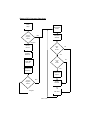
Flow
Chart
available. A word of caution concerning wall plug style AC adapter power
supplies: They are not suitable for operation of your transmitter due to their
Initial
Setup
Read Mode
Switch
Check
program
switch
Run
Set power
Send ID
Program
Record
CW ID
Time
ON
bit set
No
Program
Mode Info
Yes
No
Tone
ON
bit set
Program OFF
time info
Yes
Program Tone
Frequency
Enable Tone
output
Check
Program
Switch
Run
45 sec
ON timer
Program
OFF timer
FHT-1 • 29
poor regulation, AC ripple content and RFI susceptibility. If your supply voltage
is in the 11-12 volt range, you can expect a 600 to 800 ma current flow and
about 4 watts of the RF output power. With a solid 13 to 14 volt supply, you
can expect about 1 amp current draw and up to 5 or 6 watts of RF output
power.
IMPORTANT NOTE: If you are experimenting with this transmitter and see a
sudden and massive increase in power output and DC current, you have not
reached the promised land or created a 25 watt transmitter! Sudden surges
like that are a sure sign of amplifier self-oscillation. Kill the DC power supply
immediately, because your Q6 RF power transistor is heading to selfdestruction while probably interfering with every TV set in the neighborhood! A
poorly matched antenna along with higher supply voltages is usually
responsible for this occurring. Any prolonged "parasitic" emissions may also
overheat and destroy other components in the amplifier stages.
INSTALLATION AND PROGRAMMING OF THE MICROCONTROLLER
The following instructions are for programming the Ramsey FHT-1
Fox Hunt Transmitter. If you intend only to use a CW ID then these directions
will be all that are necessary for complete operation. When using the unit in
CW ID modes it is strongly recommended that a battery backup power supply
be added to the microcontroller. This is due to the fact that if for any reason
power is interrupted during or after programming, all the programmed
information will be lost. This voltage should be between 3 - 5V DC and can be
connected to the circuit board as shown in the parts layout diagram. The IC
draws negligible current, so 3 standard “AA” or “AAA” cells connected in series
or a surplus 3.9V lithium will work quite well. Under NO circumstances should
more than 5V DC be applied to the microcontroller.
NOTE: If you have the optional voice ID kit you’ll still need to complete the
testing instructions for CW use, but battery backup is not required.
1. Install the 16 pin microcontroller IC labeled FHT into the U2 socket.
Notice that the IC is marked with a notch, band or dot denoting pin one of
the device. Be sure to orient this component as shown in the parts layout
diagram. Be careful not to bend any of the pins underneath the body of the
component while inserting. Also,check to make sure that the IC is pushed
snug into the IC socket.
2. Now connect your keyer paddles or keying device to the three holes at
J3 marked (surprisingly enough) “paddles”. See the diagram for correct
placement.
Before you use the FHT-1 you must first program the CW ID.
Failure to properly identify a transmission is against the FCC rules.
FHT-1 • 30
MODE 0 PROGRAMMING:
The FHT-1 has 16 different modes of operation of increasing
difficulty. The mode is selected by setting the DIP switch S3. By setting
the mode you control; how long the transmitter is on the air, if a tone is
present, power level, and the time until the next transmission. Mode 0 is the
user programmable mode. You must program this mode first to enter your
ID.
1. Turn off the FHT-1.
2. Connect a small monitor earphone to J2.
3. Center the earphone adjustment pot, R41, to mid-range. You can readjust this trimmer while you are sending code into your FHT-1 to a
more comfortable level.
3. Switch S2 to Program.
4. Turn on the power.
The FHT-1 is now waiting for you to send your callsign or ID. Simply send as
you would with your keyer. The FHT-1 remembers the letters and spaces
that you send. The ID will be about 15 seconds long, or about 10 to 15
characters.
If you make a mistake simply turn off the power wait 10 seconds and turn it
back on to start over.
5. When the memory is full LED 1 will light.
6.
Set the DIP switch for the desired mode:
S3-1 enables the tone.
S3-2 enables the 45 second ON time.
S3-3 sets the output to high power.
S3-4 enables the output power high/low toggle.
7. When the switches are set as desired close either the dot or dash
paddle to enter the value.
8. LED 1 will go out and LED 2 will light.
9. Set the DIP switch for the desired OFF time. The time is set in 4
minute increments so all switches off equals 0 OFF time.
S3-1 on equals 4 minutes OFF time.
All switches on equals 15 times 4 minutes = 60 minutes OFF time.
10. Close either the dot or dash paddle to enter the OFF time value.
11. LED 2 and LED 1 will light.
12. Set the DIP switches for the desired tone frequency.
All switches off equals the lowest tone frequency.
FHT-1 • 31
All switches on equals the highest tone frequency.
For a frequency of 1000 Hz set S3-4 and S3-1 on.
13. Close either the dot or dash paddle to enter the tone frequency.
LED 2 and LED 1 will both go out.
14. Set the DIP switch for the desired operating mode.
Mode 0 is the user programmable mode. Or you may select any
other mode.
15. Switch S2 to RUN.
A complete timing cycle of the transmitter begins with the transmission
of the CW ID which takes 15 seconds, followed by a 45 second period in
which the transmitter can be off or on (keyed) with or without a tone
depending on the selected mode. Then follows the off time which can be
any length from none at all , to up over an hour. The cycle then repeats.
16. While the ID and tone are being transmitted it is time to adjust R13,
the modulation level adjustment. Listen on a receiver for best audio
quality. Ideally, a two-way radio service monitor should be used to adjust
this control.
Once the unit is initially programmed, any of the following modes may be
selected. One of these modes should suit your needs. Simply set the DIP
switch as indicated by the chart and turn the unit on.
FHT-1 • 32
As you can see mode 1
will Ramsey
send the IDKit
(15sec.)
then wait 45sec. and
The
Warranty
then start over. This is the beacon mode Identifying once per minute.
Please
carefully BEFORE
callingaor
writing
about
Mostbe
problems
Mode read
2 Identifies
then sends
tone
forin45
sec.your
sokit.
it will
on thecan
air be solved
without contacting the factory.
continuously. These modes will make the Fox easy to find for beginners.
Notice
that this 3
is through
not a "fine print"
wantchallenge
you to understand
yourthe
rights
and ours
too! All
Try modes
7 forwarranty.
a little We
more
and for
really
tough
Ramsey kits will work if assembled properly. The very fact that your kit includes this new manual is your
almost
impossible
to
find
fox
mode
15
is
only
on
the
air
15
seconds
every
assurance that a team of knowledgeable people have field-tested several "copies" of this kit straight
hour.
from
the Ramsey Inventory. If you need help, please read through your manual carefully, all information
required to properly build and test your kit is contained within the pages!
1.TROUBLESHOOTING
DEFECTIVE PARTS: It's always
easy to blame a part for a problem in your kit, Before you conclude
HINTS
that a part may be bad, thoroughly check your work. Today's semiconductors and passive components
have reached incredibly high reliability levels, and it’s sad to say that our human construction skills
have
But on rare is
occasions
a sourtocomponent
can slip through.
All our
kit use
parts some
carry thesimple
Ramsey
The not!
transmitter
very easy
troubleshoot,
providing
you
Electronics Warranty that they are free from defects for a full ninety (90) days from the date of
commonDefective
sense.parts
If you
cannot
get
any readings
on the
points
or RF
purchase.
will be
replaced
promptly
at our expense.
If youtest
suspect
any part
to be
power output,
check
and
seeforif testing
the crystal
oscillator
is running
- how?
Well,part
defective,
please mail
it to our
factory
and replacement.
Please
send only
the defective
(s),
notathe
entire
The
part(s) MUST
be returned
to us in suitable
condition
Please
take
look
atkit.
the
crystal
and see
the frequency
marked
onfor
it,testing.
it should
bebe
aware that testing can usually determine if the part was truly defective or damaged by assembly or
16.280
MHz
(1/9
of
146.52
MHz),
right
in
the
middle
of
the
HF
shortwave
usage. Don't be afraid of telling us that you 'blew-it', we're all human and in most cases, replacement
broadcast
easily
received on any shortwave radio. You should be able
parts
are very band,
reasonably
priced.
tto "hear" the oscillator running quite easily. If crystal oscillator operation is
2. MISSING PARTS: Before assuming a part value is incorrect, check the parts listing carefully to see if
let'ssuch
move
a step
The aoscillator
followed
by (such
a tripler
itconfirmed,
is a critical value
as a on
specific
coil orfurther.
IC, or whether
RANGE of is
values
is suitable
as
stage,
and
3 times
16.280
MHz
is 48.840
Oncemissing
againpart
this
signalIf you're
can
"100
to 500
uF").
Often times,
common
sense
will solve MHz.
a mysterious
problem.
missing
five 10K
resistors
and received
fiveas
extra
resistors,One
you can
prettytripler
much be
assured
be tuned
on aohm
nearby
receiver
such
a 1K
scanner.
more
follows
that the '1K ohm' resistors are actually the 'missing' 10 K parts ("Hum-m-m, I guess the 'red' band really
and
that
moves
us
up
to
the
final
146.520
MHz
output
frequency,
easily
does look orange!") Ramsey Electronics project kits are packed with pride in the USA. If you believe
tuned
onana incorrect
two meter
rig.
Thisa procedure
will lead
usassembly
to the final
amplifier
we
packed
part or
omitted
part clearly indicated
in your
manual
as supplied
with
the basic
kit bywe
Ramsey,
please write
or call
information
on theinspection.
part you need and proof of
stages
where
can pretty
much
dous
a with
thorough
visual
kit purchase
Common problems to look for are solder bridges or interchanged
3.
FACTORY REPAIR
OF ASSEMBLED
KITS:
capacitors
- "hum-m-m-,
that's not
a .001 uf where a 100 pf should be is it?"
To qualify for Ramsey Electronics factory repair, kits MUST:
If
there
is
a
problem
in
getting
the
modulation
working, a scope or audio
1. NOT be assembled with acid core solder or flux.
amplifier
will allow
tracing
2.
NOT be modified
in any
manner.down any problem in short order. The audio drives
3.
BEvaractor
returned indiode
fully-assembled
form,
not partially
assembled.
the
D1. How
about
keying
of the transmitter? Check to be
4. BE accompanied by the proper repair fee. No repair will be undertaken until we have received the
sure that
the
PTT
line
is
switching
off
and
on. If you hear a AC hum on the
MINIMUM repair fee (1/2 hour labor) of $18.00, or authorization to charge it to your credit card
transmitted
signal, usual causes are RF getting back into the power supply
account.
5.
a description
of theantenna.
problem and legible return address. DO NOT send a separate letter;
orINCLUDE
a bad VSWR
on the
include all correspondence with the unit. Please do not include your own hardware such as
These short
checks
in
no
way cables,
detail external
any and
all problems
that
rear their
non-Ramsey cabinets, knobs,
battery
packs and the
like.can
Ramsey
Electronics,
Inc., reserves
the right
refuse
on ANY item
in which
we find
excessive
ugly head,
but should
get you
on tothe
wayrepair
to solving
most
errors.
We'd
like to
or damage
due to construction
To assist customers
such situations,
be ableproblems
to foresee
a problem
a buildermethods.
may encounter,
but thein sheer
number
Ramsey Electronics, Inc., reserves the right to solve their needs on a case-by-case basis.
of parts and the permutations and combinations of installing them makes an
The
is $36.00exact
per hour,
regardlessimpossible.
of the cost of the
kit. Please
understand
that our technicians
list repair
of precise,
solutions
If you
run into
a roadblock,
gather
are
volunteers
and and
that set-up,
testing, diagnosis,
repair
and repacking
and paperwork
can take
all not
your
thoughts
information
and give
a call
to the factory
for some
help.
nearly an hour of paid employee time on even a simple kit. Of course, if we find that a part was
If you elect
to enlist there
the help
localtoexpert,
great
- but
berealize
surethat
theourexpert
defective
in manufacture,
will be of
no a
charge
repair your
kit (But
please
is qualified
- no
forbetween
havinga someone
youburned
downout
the
technicians
know
the need
difference
defective partlead
and parts
or wrong
damagedpath!
through
improper
use oryou
assembly).
Remember
may always return the kit for factory service, and there's no
charge
if the
problem
theour
warranty
the
page ofyou
this
4.
REFUNDS:
You
are given is
tenour
(10) fault.
days toSee
examine
products. on
If you
arelast
not satisfied,
may
manual.
return
your unassembled kit with all the parts and instructions and proof of purchase to the factory for a
full refund. The return package should be packed securely. Insurance is recommended. Please do not
cause needless delays, read all information carefully.
OTHER ENCLOSURE RECOMMENDATIONS
FHT-1 • 33
Fox Hunt Transmitter FHT-1
Quick Reference Page Guide
Introduction to the FHT-1 .............. 4
How it works ................................. 5
Parts list ........................................ 6
FHT-1 Assembly instructions ........ 8
Parts Layout diagram .................... 9
Schematic diagram ..................... 18
Initial testing ................................ 21
Programming ............................... 24
Troubleshooting ........................... 28
Ramsey kit warranty ................... 31
REQUIRED TOOLS
• Soldering Iron (Radio Shack #RS64-2072)
• Thin Rosin Core Solder (RS64-025)
• Needle Nose Pliers (RS64-1844)
• Small Diagonal Cutters (RS64-1845)
• <OR> Complete Soldering Tool Set
(RS64-2801)
ADDITIONAL SUGGESTED ITEMS
• Soldering Iron Holder/Cleaner (RS-64-2078)
Price: $5.00
Ramsey Publication No. MFHT-1
Assembly and Instruction manual for:
RAMSEY MODEL NO. FHT-1 "Sly Fox"
FOX HUNT TRANSMITTER KIT
RAMSEY ELECTRONICS, INC.
793 Canning Parkway
Victor, New York 14564
Phone
(716) 924-4560
Fax
(716) 924-4555
FHT-1 • 34
TOTAL SOLDER POINTS
373
ESTIMATED ASSEMBLY
TIME
Beginner .............. 11 hrs
Intermediate ......... 6.3 hrs
Advanced ............. 4.7 hrs