1
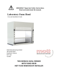
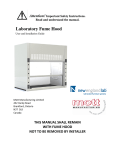
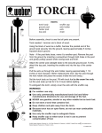
Manual For Snuffer 45-90/N & 45-130/N Compressed Air Foam Systems . . Snuffer Operator & Maintenance Manual CONTENTS Section Page Safety Information Snuffer Applications 6 8 General Information & Requirements Snuffer 4000 Series 10 Hoses 11 Nozzles & Valves 12 Foam 13 Foam Types 14 Installation 15 Operating Instructions Before Starting 16 Start Engine & Operating Unit 17 CAFS Combining Valve 17 Snuffer unit shut down 19 Drain unit 20 Drives & Drive Belts 22 Belt Adjustment Water Pump & Plumbing 23 Operation Self-cleaning Filter Maintenance Hydraulic Injector Operation Operation 24 Maintenance 25 Air System Including Air Compressor 27 Operation Maintenance Engine (see engine manual included) 28 Electrical System 28 Specification Guide 29 Trouble Shooting Guide 34 Safety Information for Snuffer C.A.F.S. Be sure to read and understand this manual and the Engine manual (if so equipped) before operating the Snuffer to ensure safe operation. The Snuffer compressed air foam system is a highly versatile fire protection and suppression device and is the system of the twenty-first century. NOTE: This owner’s manual should be read before any use or maintenance of the Snuffer is carried out. This manual should be reviewed periodically to keep familiar with all functions. In addition to this, frequent training should be attended. If you don't read this, you could: 1. Cause harm to yourself or co-workers. 2. Cause harm to the public. 3. Cause harm to the Snuffer or accessories therefore voiding warranties. WARNING The Snuffer is an industrial compressed air foam system and should be operated with great care to ensure accidents are avoided. A qualified instructor in the proper operation of this equipment should train operators of the Snuffer. This manual must stay with the Snuffer at all times. Important! The serial number of your unit is on the back of the front panel. Please record this number along with the unit’s model number in the space below. Please refer to your model number when you call your distributor or The SNUFFER Corporation, for information, parts and service. Model Number Serial Number Purchase Date This decal is located on the back of the Control Panel. Unit Serial #: Engine Serial #: The Decal is located on the back of the Engine (looking at it from the front of the Snuffer). Compressor Serial #: Is located between Cylinder Heads of the Air Compressor. Safety Information for Snuffer C.A.F.S. This safety alert symbol means Attention! Become Alert! Your safety is involved! The safety alert symbol identifies important safety messages on the Snuffer and in the manual. When you see this symbol, be alert to the possibility of personal injury or death. Follow the instructions in the safety message. WHY IS SAFETY IMPORTANT TO YOU? 1. Accidents disable and kill. 2. Accident cost. 3. Accidents can be avoided. SIGNAL WORDS: Note the use of the signal words DANGER, WARNING, and CAUTION with the safety message. The appropriate signal word for each has been selected using the following guidelines: DANGER An immediate and specific hazard that will result in severe personal injury or death if the proper precautions are not taken. WARNING A specific hazard or unsafe practice, which could result in severe personal injury or death if proper precautions are not taken. CAUTION Unsafe practices which could result in personal injury if the proper precautions are not taken, or as a reminder of good safety practices. Snuffer C.A.F. Applications Compressed Air Foam – Low expansion/high energy foam The Snuffer, with the Chemical Injector and Air Compressor ON, makes low expansion/highenergy (high-density) foam known as C.A.F. The operator can make several different low expansion foams by changing the Flow Control from the Wet to Dry position and by operating with the smooth bore tip on or off. This will produce foam from a slurry for fighting fires to dry foam for fire prevention. Used in this manner, the Snuffer can be utilized for most fire fighting and fire prevention applications, except in restricted areas where only water is allowed to fight fires. The results are that the fire is suppressed faster; there is a significant reduction in the quantity of water required; there is less water damage and less pollution. Foam injection rates are low 0.2 to 0.4%, 0.2% injection rate is equivalent to 2 gallons of foam chemical mixed in with1000 gal of water. C.A.F. foam can provide much better structural protection than what is obtainable with the use of plain water or aspirated foam (low expansion/ low energy). The dry foam that is produced by C.A.F.S. is like shaving cream, as shown below and will stick to vertical and overhead surfaces. Compressed Air Foam Theory The tiny bubble structure in C.A.F. it is much effective than aspirated foam in extinguishing fires and protecting exposures. Compressed air foam will stick to walls and ceilings, holding the water in contact with the fuel. When using plain water, 90 to 95% of the water ends up on the floor. In general C.A.F. is 7 to 15 times better in fire suppression as compared to plain water and up to 20 times more effective on overhead surfaces. Class A foam is 15 to 30 times more effective than plain water in extinguishing petroleum fires (Class A foam should not be used on petroleum fires where rescue is involved). Tire fires are easily controlled with an initial wet foam application followed by a dry foam application. Class A, AB, B, and ABD foams are all made more effective when applied as compressed air foam. Aspirated Foam – Medium to high expansion foam The Snuffer, with the Chemical Injector ON and the Air Compressor OFF, will allow the operator to use medium to high expansion (low density/low energy) aspirating devices for fire control and prevention. Foam rates are generally 0.5 to 1.0% for Class “A” and 1.0% for Class “B”. Aspirated Foam Outlet A aspirated foam system is optional on the 45-90 system, if not orded at the time of purchase the systems can still be added in at a later time. The aspirated foam systems is standard on the 45-130 systems. A aspirated foam systems is NOT available on the 45-90N and 45-130N systems, and can not be added into the system at a later time. A remote system can be added on a truck and connected to the Snuffer systems. With a aspirated system, you will find the same hydraulic injector as used in the Compressed Air Foam System. The difference between the C.A.F.S. and aspirated system, is that the air is introduced into the water stream at the nozzle. This creates big, medium and some small bubbles in the foam structure. Aspirated foam is technically known as low expansion, low energy foam. Medium expansion and high expansion generators can also be installed at the end of the foam line. Water travels through a self-cleaning filter and then to the hydraulic injector. From there the solution travels down the hand lines and to the aspirated nozzle where air is introduced into the water stream. This foam system has about 100% better cooling and 2 to 4 times the knock down ability of water. Operator’s Controls Decal Locations on the Snuffer Important! The serial number of your unit is on the back of the front panel. Please record this number along with the unit’s model number in the space below. Please refer to your model number when you call your distributor or The SNUFFER Corporation, for information, parts and service. Model Number Serial Number Purchase Date Warning Rotating Parts This decal is located on the inside of the access door of the Snuffer. This of decal is located on the back of the Control Panel. This decal is designed to warn the hazard of the Drive Unit Serial #: Belts for both the Air Compressor and the Water Pump. Hands, loose clothing or anything elseismay become Engine Serial #: The Decal located on the back of the Engine (looking at it from the entangled in the Belt while front the Snuffer is in operation and of the Snuffer). can cause severe injury or death. Compressor Serial #: Is located between Cylinder Heads of the Air Compressor. Pump Serial #: The decal is on the face of the Pump. Injector (s) Serial #: Is stamped into the bottom of the Injector Base. For Compressed Air Foam a 1.50” (38mm) pistol grip ball valve with a minimum 1.38” (35mm) Snuffer 45-90/N & 45-130/N Compressed Air Foam System Principals of Operation When the engine is started, water from the pump flows through a check valve and then is divided into a plain water circuit and one foam circuits. The water in the foam circuit flows through a self-cleaning filter and into a Compressed Air Foam line, and into an Aspirated Foam line(optional). The water is then restricted per line by use of line restrictors that limit the flow through each injector to 40 to 45 gpm (average 45 gpm). Water then flows through the water driven (hydraulic) foam injector(s). The water flow in the injector pushes a large piston assembly up and down, achieved by two sets of reversing valves opening and closing in sequence. Each time the large piston moves upwards, a smaller piston connected to the main piston assembly draws the foam concentrate from a pail or tank and forces it into the center of the water stream. This is now called a foam solution. In the Compressed Air Foam line, with the air compressor switch “ON” compressed air is injected into the foam solution with secondary agitation accomplished by a stationary mixer. In the Aspirated foam line, the foam solution runs as is through the line to the hand line nozzle where air is then introduce into the foam solution by an aspirating nozzle. Operating Suggestions The fire fighter quickly learns the best way to use CAFS foam types to their best advantages. Initial structural fire suppression (fibrous materials). Wet foam WET/DRY valve open, with a 0.88” (22mm) or a 1.06” (27mm) tip on. Inside structures (petroleum fires, rubber and car fires). Medium foam WET/DRY valve open, with tip off Grass and fibrous material fires Wet foam WET/DRY valve open, with a 0.75“ (20mm) tip on. Protection and final mop-up of automobile, petroleum oil and gasoline fires. Extra Dry foam WET/DRY valve in “DRY” position, with tip off. Certain units are equipped with an extra wet foam attachment for grass fire control, thus generally smaller diameter tips, such as 0.50“ (13mm) or 0.75“ (20mm) should be used. NOTE: 1.00” (25mm) hand lines are not recommended for use on structural fires. NOTE: Fire fighters report that they often obtain better knock down of most petroleum fires by lobbing on the foam. Hoses Standard 1.50” (38 mm) hose should be used on each Compressed Air Foam outlet, except for inside structural attack. For inside structural attack, it is highly recommended that at least 50 ft. (15 m) of crimp resistant hose be connected to the pistol grip valve. A regular single or double-jacketed hose filled with compressed air foam can be crimped because of the low operating pressures, resulting in loss of flow. Weeping forestry hoses are not recommended as this allows the air to escape, which reduces the effectiveness of the foam and discharge distance. To make good Compressed Air Foam it is recommended that 150 ft. (45m) of 1.50” (38mm) hose or 200 ft. (60m) of 1.75” (45mm) hose be used. The hose should have a rough bore to maximize mixing of the air and foam solution. This will result in the most uniform bubble structure, giving the highest quality and most effective foam. Smooth wall hose will work but it takes greater lengths to accomplish the same scrubbing action within the air and foam solution. Operators often use compressed air for 10-15 seconds to flush out hand lines after they have run water through these lines. This is very beneficial for cold weather clean up operations. NOTE: 1.00” (25mm) hand lines are not recommended for structural fires but they can be used for wild land mop up operations. Recommended Hoses 1.50” (38mm) Line • 150 ft. (45m) of single or double jacket fire hose is recommended (non weeping). • Standard hose 1.50” (38mm) or 1.75” (45mm) Interior Attack hose 1.50” (38mm) Neidner non-crimping (50 ft. (15m) minimum). This hose is recommended for interior attacks as it does not kink passing through doors, up stairs. Nozzles & Valves Important! The serial number of your unit is on the back of the front panel. Please record this number along with the unit’s model number in the space below. Please refer to your model number when you call your distributor or The SNUFFER Corporation, for information, parts and service. Model Number Serial Number Purchase Date This decal is located on the back of the Control Panel. Serial #: It Unit is very important to understand when and how these settings should be used. When Compressed Air Foam is being applied the fire fighter can open and close the valve quickly Engine Serial #: The Decal is located on the back of the Engine (looking at it from the without fear of causing water hammer. front of the Snuffer). Recommended Nozzle#:or tip sizes forbetween 1.50” (38mm) C.A.F. lines are:Air Compressor. Compressor Serial Is located Cylinder Heads of the Straight Pump• Serial0.75” #: (19mm) The decal Bore is on Nozzle the face of the Pump. • 0.88” (22mm) Straight Bore Nozzle • (s) Serial 1.06” (27mm) Injector #: Is Straight stampedBore into Nozzle the bottom of the Injector Base. • Akron Saberjet (or equivalent) fog/straight stream nozzle/valve. (This nozzle cannot produce dry foam) For Compressed Air Foam a 1.50” (38mm) pistol grip ball valve with a minimum 1.38” (35mm) ball opening should be used. The nozzle or tip used should be a straight (NOT TAPERED) Aspirated Foam & Nozzles smooth bore, streamTips straighteners should not be used. The Aspirated Foam System comes standard with a 2:20 adjustable nozzle for best A good point to remember is that the smaller the nozzle/tip size the wetter the foam becomes performance. It can also be used with a combination fog and stream nozzle. However this (no matter what the system is set to), a smaller nozzle/tip size also increases casting distance. nozzle, in most fire situations, is not as at size making The disadvantage is that is smaller theeffective nozzle/tip the useful volumefoam. of foam produced is reduced. The nozzle valve must always be opened or closed slowly to reduce water hammer. The nozzle/tip should be easily removable for making medium and extra dry foam. When applying dry foam, where long casting distance is not required, an open valve with no tip nozzle is very effective. Inside Straight Bore Tip A ¼ turn quick coupler set on the nozzle/tip and valve make it very easy to remove the nozzle/tip. 0.75" (20mm) 0.88" (22mm) 1.06" (27mm) Snuffer position Tip ON Tip OFF Tip ON Tip OFF Tip ON Tip OFF Dry Wet Extra Dry Medium Extra Dry Dry Extra Dry Wet Extra Wet Wet Wetter Medium Wet Medium again. NOTE: If water pressure does not show after 10-15 seconds, it is sometimes necessary to momentarily open a discharge valve to relieve an air lock situation. FOAM Making good quality foam is not hard to do, but it does require some study, training and practice. It is necessary for fire fighters to learn how to read foam type and how it is applied to various surfaces and fires. Class A Foam Use a good quality foam chemical that is tolerant to the cold if used with water at temperatures below 12°C (55°F). With water at temperatures above 12°C (55°F) the chemical should make good wet foam when the chemical injector is set at 0.2% and good dry foam at 0.3% injection rate. In cold temperatures you may have to increase the foam percentage by 1/10 of a percent to achieve the same quality foam. Very dry foam, that makes “snow flakes”, is not desirable, as it does not contain enough water to give adequate protection. When using different brands of foam, become familiar with their properties, when used in the Snuffer and before using it at an actual fire. It’s important to remember that higher chemical rates are not better. In most cases a higher rate produces thicker foam, which will not run into fibrous material, crevices, and the foam becomes less effective. Class B Foam (AFFF) Use a good 1.0% AFFF set at 0.6% injection rate for non-rescue, and 1.0% injection rate for rescue situations. Application of AFFF compressed air foam approximately doubles the effectiveness when knocking down fires as compared to water driven stream enductor or injector systems. This is due to the uniform tiny bubble structure that the Compressed Air Foam System produces. The A & B foams used by the department should be tested to make sure they are compatible. Other Foams Certain ABD foams can also be used effectively to cut off three-dimensional fires and certain metals, such as solid magnesium, titanium shavings. CAUTION: It is important that fire departments are trained well on any particular foam that they are using. They must make sure that when changing to a new brand of foam it is tested for compatibility with other foams used by the department, and that adequate training takes place. Foam types Suggested uses for the five types of Compressed Air Foam. This chart shows recommended nozzle/tip sizes and what type of foam is produced when the system is set to the “DRY” or “WET” position, along with either the Nozzle/tip “ON” or “OFF” the hand line valve. Important! The serial number of your unit is on the back of the front panel. Please record this number along with the unit’s model number in the space below. Please refer to your model number when you call your distributor or The SNUFFER Corporation, for information, parts and service. Dry Foam 20 to 25 gpm (64 L/min). 1. Dry Foam 10-12 times expansion. Model Number Serial Number Purchase Date • Produces 250-300 gpm (950-1140 L/min) of Dry foam (25 gallons (95 L) of water). • Protection mop up on structural fires, after a fire has been knocked down. 2. Extra Dry Foam 12-15 times expansion. • Produces 250-375 gpm (1140-1420 L/min) of Extra Dry foam (25 gallons (95 L) of water). This decal is located on the back of the Control Panel. • Used to put an extra layer of foam inside a car or inside house walls, and for Unit Serial #: long-term exposure protection. Engine Serial #: The Decal is located on the back of the Engine (looking at it from the of the Snuffer). Wet Foam 40 to 50front gpm (160 L/min). Compressor #: Is located between Cylinder Heads of the Air Compressor. 3. Wet FoamSerial 3-4 times expansion. • Produces 150-200 gpm (570-750 L/min) of Wet foam (50 gallons (160 L) of Pump Serial #: The decal is on the face of the Pump. water). • Often used for grass fire control. Occasionally on external structure fires, Injector where (s) Serial #:casting Is stamped the bottom theeffective Injector as Base. extra distanceinto is required - notofas medium foam. 4. Medium Foam 8-9 times expansion. For Compressed Air Foam a 1.50” (38mm) pistol grip ball valve with a minimum 1.38” (35mm) • Produces 400-450 gpm (1515-1700 L/min) of Medium foam (50 gallon (160 L) ball opening should be used. The nozzle or tip used should be a straight (NOT TAPERED) of water). smooth bore, stream straighteners should not be used. • Used on more than 90% of fires that departments come in contact with (structural, industrial, rubber, automobile, petroleum and synthetic materials). It also doesto a remember good job ofisproviding protection. A good point that the smaller the nozzle/tip size the wetter the foam becomes (no matter what the system is set to), a smaller nozzle/tip size also increases casting distance. The disadvantage is that is smaller the nozzle/tip size the volume of foam produced is reduced. Extra-Wet Foam 80-100 gpm (300-380 L/min). 5. Extra Wet Foam 1-2 times expansion. The nozzle/tip should be easily removable for making medium and extra dry • Produces 90-180 gpm (340-680 L/min) of Extra Wet foam (90 gallons (340 L) foam. When applying dry foam, where long casting distance is not required, an of water). open valve with no tip nozzle is very effective. Straight • Used on grass fires and often-used on materials, garbage dumps Inside Bore Tip the foam or valve container fires. A ¼ turndeep-seated quick couplerfires set in onfibrous the nozzle/tip and make it very easy to remove the nozzle/tip. 0.75" (20mm) 0.88" (22mm) 1.06" (27mm) Snuffer position Tip ON Tip OFF Tip ON Tip OFF Tip ON Tip OFF Dry Wet Extra Dry Medium Extra Dry Dry Extra Dry Wet Extra Wet Wet Wetter Medium Wet Medium Installation When the Snuffer is combined with a water tank on a truck with enclosure the following is recommended: 1. The system should be installed onto a Rollout skid frame for easy maintenance and servicing. 2. In order to allow the Snuffer to move in and out on the Rollout skid frame, sufficient hose lengths must be provided to prevent crimping. 3. A water tank level gauge should be installed. 4. For greater operator convenience the Snuffer systems should be equipped with a 1.50” (38mm) Hydrant Fill line, this line will allow the operator to fill the water tank using a external pump source. NOTE: A Tank fill valve can also be installed. This allows the operator to fill the water tank by using the Snuffer pump. Gasoline Engine Preparation Fuel line can be taken directly from the truck’s fuel tank as long as a small electric fuel pump is installed, or the unit can be equipped with a marine type, portable fuel tank with quick connectors. Position the tank away from the engine in a well-ventilated area.. Before Starting Check the engine, and air compressor oil levels. A. For water tank equipped systems, make sure the valve is open to draft from an external source of water or from the tank. B. Use a draft line 2.50” (64mm) or larger that is equipped with a reliable Suction Strainer. Make sure that the suction line has a smooth gentle curve down to the water source. The draft line should never curve upward and then down to the pump, as it may cause air locks. C. Foam chemical lines should be connected and foam foot valves fully inserted into the respective pails or tanks. F. Make sure that all drain cocks and drains are closed. D. Connect foam and water hand lines. A 1.50” (38mm) hose is recommended and should be attached to each outlet being used. Starting the Snuffer Unit A. Start the engine (making sure that the air compressor switch is in the OFF position). Move the choke lever to full open then turn the key to the start position (throttle at approximately one third open). When the engine starts, check to make sure water pressure is showing on the water gauge. B. If water pressure is not showing: When a unit is equipped with a draft line and occasionally from an onboard water tank, operate the air primer by opening the air primer valve until water is visible at the air primer outlet. When water pressure just starts to show on the gauges, shut off the primer valve. Water pressure should stay showing on the water gauge with discharge valve(s) closed (static). If after 20-30 seconds the water pressure continues to drop, shut the unit down and check suction hose connections for leaks, etc. Then go through the priming sequence Important! The serial number of your unit is on the back of the front panel. Please record this number along with the unit’s model number in the space below. Please refer to your model number when you call your distributor or The SNUFFER Corporation, for information, parts and service. C. WithModel the Snuffer running and water pressure showing, increase the engine rpms. Date Number Serial Number Purchase The water pressure should be between 130 and 140 psi. C.A.F.S. Combining Valve The 45-90 and 45-130 systems can be optional C.A.F. combining This decal is equipped located onwith theaback of the Control Panel. valve. This valve Unit allows Serial the #: operator to combine the two foam line (C.A.F. and Aspirated foams) into one line. Keep in mind that in the Aspirated line there is only a foam solution, so what is being added to the Engine #: foam solution The Decal located onincreasing the back of Engine (lookingofatthe it from C.A.F. lineSerial is more and is water, thus thethe casting distance foam.the front of the Snuffer). Compressor Serial #: Is located between Cylinder Heads of the Air Compressor. Hydraulic Foam Injectors Pump Serial #: The decal is on the face of the Pump. The foam injector works in the following manner. When a hand line valve is opened, water flows into Injector the hydraulic (s) Serial injector, #: which acts on a large and small located Is stamped into the bottom of thepiston Injector Base.within the injector bell housing. A set of reversing valves is used to allow the pistons to move up and down. Every time the For Compressed Foam athe 1.50” (38mm) ball valve a minimum (35mm) large pistons moveAir upwards, small pistonpistol pulls grip chemical fromwith the pail or tank. 1.38” The foam ball opening should be used. The nozzle usedstream shouldfor bebetter a straight (NOT TAPERED) chemical is then injected into the center of or thetipwater mixing. This unit operates on smooth bore, straighteners should be used. water flows of 2stream -50 gpms and pressures of not 10-120 psi and is capable of lifting foam from a pail or tank located up to 7-9 ft below the injector. Foam tanks or pails should not be located much above the level of theto injector as a siphon action may the occur if plain water is used thebecomes injector. A good point remember is that the smaller nozzle/tip size the wetterthrough the foam (no matter what the system is set to), a smaller nozzle/tip size also increases casting distance. The disadvantage is that is smaller the nozzle/tip size the volume of foam produced is reduced. The next procedure is to charge the hydraulic foam injection system using the following steps: The nozzle/tip should be easily removable for making medium and extra dry foam. When applying dry foam, where long casting distance is not required, an open valve with no tip nozzle is very effective. Inside Straight Bore Tip A. Connect a container of good foam concentrate. Normally 1.0% A or B, and 0.4% for ABD. B. Connect the clear plastic line with foot valve, to the bottom of the injector stem. To reduce the chemical from splashing, drill a hole through the cap of the pail the same size as the clear plastic line. Disconnect the line from the foot valve and place the clear line through the cap and re-connect the foot valve. C. Make sure all connections are tight and that the CAFS foam injection rate is set at 0.3 or 0.4% (Class A), depending on the quality of foam used. Aspirated foam rate, if so equipped, should be set at 0.5-1%. This is done by first loosening the collar where the injector stem meets the injector body ½ - 1 turn. Once this is done the injector stem can be turned up or down to adjust the rate. It may be necessary to hold the clear plastic calibration indicators with the other hand. When the desired rate has been selected, lightly hand tighten the collar. In most cases if the collar is set correctly it is not necessary to loosen the collar. D. Slowly open the desired CAFS line (engine should be set at ¾ throttle or better). WARNING: Always have someone holding the pistol grip nozzle valve on the end of the line when operating hand lines for any reason. E. Turn the switch located at the top of each injector to the Bypass (“B”) center position for a second and then turn the switch to the ON position. The operator should, after a few seconds, be able to see the chemical flowing through the clear suction tube. If the Injector does not start, turn the switch to the OFF position and repeat the above procedure. It will take a few seconds before you see the foam concentrate moving up the clear plastic line. This process can be sped up somewhat by filling the clear plastic supply line with foam chemical, this is done by jog priming (moving the line up and down quickly in the pail until the foam is ¾ the way up the line or better). On start up, air slugging (line jerking) in the C.A.F.S. discharge line is normal. The flow will gradually clear up and a smooth foam discharge will occur. C.A.F.S. discharge distance will greatly increase as the foam solution and air stabilizes. NOTE: C.A.F.S. air slugs may also occur if the foam rate is too low for the particular foam you are using. An easy way to tell this is to move the rate up 1 or 2 points and if the slugging clears up then the problem was the injection rate. This is especially prevalent when using very cold water or poor quality foam. Snuffer Operation & Maintenance 45-90/N & 45-130/N Page 18 An easy way to tell whether the foam setting is correct, after the C.A.F. system is up and running, is th to place the Wet/Dry valve in the Dry position and remove the 1 and 1/16 inch tip from the 1 3/8” ID pistol grip ball valve. The system should operate with a minimum of air slugging after ten to 15 seconds. If it does not do so, then the rate needs to be increased slightly. However, remember that more is not better. Use only enough foam chemical to do the job. NOTE: The CAFS discharge nozzle should be a 1 1/16” straight smooth bore nozzle (not tapered). F. Repeat this operation for the second C.A.F.S. line. NOTE: During operation the engine should be run at 2500 to 2600 rpm. This should generate a static pump pressure of 125 to 130 psi. WARNING; Do not open a discharge valve unless a hose is attached to the related discharge port. Injury may occur if hose is not coupled to the discharge port. C.A.F. outlets must never be capped. Air Regulator When air tools are used, the air regulator can be used to set their maximum operating pressure (make sure the airline fitting matches the air chuck or connector). NOTE: You can operate one of the CAFS foam outlets and also the aspirated foam outlet when using the external air chuck. Snuffer Unit Shut Down (Warm Weather) 1. Reduce engine RPMS by 1/3 and operate for 1-2 minutes. 2. Shut off Engine. 3. Leave the system fully charged with the injector switch in the ON position. CAUTION: If any adjustments or maintenance is to be performed on the Snuffer unit the procedures must not be performed until all of the system pressure has been relieved. This is achieved by opening the discharge valves very slowly. Once the maintenance or repairs have been done, the system must always be tested to make sure that it is making foam, before returning the unit into service. In very cold weather conditions, if the truck’s coolant heater can not keep the Snuffer area warm, it may be necessary to operate the engine (Snuffer system) until the unit is returned to the fire station. However, there must be water in the tank and some water pressure showing on the water gauge to avoid burning out the pump seal. Drain the Unit to Prevent Freeze up or for Storage If there is a chance of freezing temperatures, it is best to place the unit inside a heated enclosure (self contained or building). Information on self-contained winter enclosures is available from your local dealer. Before shutting down the unit, and with the hand lines operating, it is necessary to shut the switch off at the top of the injectors. In this way the injectors can be properly drained. 1 Shut off engine. 2 Remove Chemical Suction Line from Hydraulic Injector. 3 Open CAFS Valve(s) and Plain Water Valve. WARNING: System may be under pressure. Relieve pressure with great care. 4. Open drain Cocks or Valves at the following locations: 5. Open valve at the bottom of the Water Filter. 6. Remove the Bell Housing from the Hydraulic Injector. Remove the Piston from inside and allow to air dry. 12. Remove the stem from the Injectors. Removed nut on bottom of injector and pull stem out. Drives & Drive Belts Air Compressor The Air Compressor is driven by an automotive style serpentine belt. Tightening the air Compressor as achieved by turning the circle tightener on the engine.. To tighten the Air Compressor drive belt, proceed as follows: Loosen the three 7/16“ bolts, lift the handle of the circle tigthener until the belt cannot be twisted more than 90° by fingers. Then retighten the three 7/16” bolts. Water Pump The 45-90/N systems use a cog type belt to drive the water pump, while the 45-130/N systems use a eagle drive cog belt to drive the water pump. To tighten the Water Pump drive belt, proceed as follows: Loosen the Idler Pulley pry down on the pulley and retighten the bolt. The belt should be tightened to a point where there is about 3/8” slack in the under side of the belt. When this is accomplished, secure the bolt on the water pump tightener pulley. It is necessary to recheck the belt tension after 10 to 20 minutes of operation. Water Pump & Plumbing Operation The Snuffer 45-90/N and 45-130/N systems uses a centrifugal single impeller water pump. A check valve is located above the pump and is a requirement for the operation of the air primer. Self-Cleaning Filter Maintenance Water from the pump flows through a self-cleaning filter. This filter should be checked often in the first few hours of operation and periodically to see if the filter is being flushed effectively or not. If the screen is partially plugged clean it in warm water with a toothbrush. To inspect the filter screen: A. Shut off the Snuffer unit and release all system pressures. B. Open the drain valve for the required filter. Disconnect the drain line from the bottom of the filter by pulling back on the collar of the quick disconnect. Slowly unscrew and remove the filter housing. C. Remove the screen and inspect condition and foreign material build up. If foreign material builds up is excessive it may mean that the operator is not purging the filter often enough or not allowing enough water to continuously flow out of the valve at the bottom of the filter body. It should be noted that if rusty or muddy water is used, the valve on the self-cleaning filter should be opened fully to allow 8 to 10 gpm of water to flow out of the filter for 4 to 5 seconds of operation. This action should keep the filter screen clean. The operator, by removing the filter screen from the canister, can then judge the best purge intervals. With very dirty water it may be necessary to run the filter valve continuously. NOTE: 1. When reassembling the filter canister HAND TIGHTEN ONLY. 2. On disassembly of the filter canister from the body, if the screen is difficult to remove from the canister, it is usually due to foreign material at the base of the screen. If it becomes necessary, the fitting on the bottom of the canister can be placed in a vice and the black stem inside the screen can then be screwed out of the body, which will release the screen. Hydraulic Injector Operation To start the hydraulic injection unit: A. Place the switch in the center position for a second and then to the ON position NOTE: The unit should be running above half speed, with the discharge valve open to allow water to run out the line. B. Foam concentrate is then pulled from the pail or tank by the injector. To ensure that it is operating, check to see that the chemical is moving in the clear suction tube. If the foam is not moving after 4 or 5 seconds, repeat steps A & B. The foam line can be pre-primed as mentioned previously. Adjusting foam rate 1 2 3 Loosen lock nut slighty. Turn adjustment nut to required percentage. Retighten lock nut. Injector Maintenance A. Stop the engine and release all system pressure by opening the discharge valves. B. Remove the blue bell housing. It is hand tightened only and is equipped with a large diameter 'O' ring to prevent leakage. C. Lift out the piston and reversing mechanism. Occasionally the piston unit will lift off with the bell housing. Care must be taken not to drop it. Clean and rinse the Filter in clear water. If it is hard to clean, use a toothbrush to gently brush the inside of the filter while running it under warm water. If the filter still does not come clean, soak it in warm water for several minutes and repeat the cleaning procedure. If you find that the filter on the Hydraulic Injector(s) is often clogged, you can install filter screens with finer mesh. The Snuffer comes standard with a 100-mesh filter, but 200 mesh are available. The finer the mesh, the longer the purge periods must be in order to keep the self cleaning filters clean. HAND TIGHTEN ONLY. If any leakage occurs, check the 'O' rings for placement or damage. NOTE: It is recommended that you periodically dismantle the entire Injector, thoroughly rinse it with water and re-assemble after having lubricated the seal with a silicone lubricant. Any air leakage, impurity or a seal failure can interrupt the injecting function. Periodically check that all of the seals are clean and in good shape. To Re-assemble the Injector: Before re-assembly ensure that the Filter Supports and Bell Housing "O" Ring Seal are clean and free of foreign bodies, then proceed in reverse order to the above. ** Important in all cases tightening must only be done by hand** Changing seals in the injector assembly (white part) **Important use NO TOOLS, hand tighten only** Piston Plunger Seal A. Relieve the pressure system by opening the discharge valves, then unscrew the Bell Housing by hand and remove. B. Remove the Piston Assembly (holding it upright). C. Remove the Seal. 1 Cleaning and re-assembling of the Injector Chemical Suction Valve: Unscrew the Plastic Nut marked as "8” and pull downward to release the Check Valve. 2 Rinse thoroughly the different parts, 2 to 7, with clear water and re-assemble as indicated. 4 3 5 IMPORTANT NOTES: 6 Any time the Injector is completely disassembled, upon reassemble the Notch (A) in the upper portion of the diffuser is placed over the peg in the bottom housing of the injector. This way, the chemical flow injection port is on the outlet side of the Injector. Screw the jam nut (B) onto the diffuser until the nut jams against the housing, screw in the retaining screw (C) into the pre drilled hole in the jam screw. Insert the stem into the diffuser A and move up and turn the lock nut (D) onto the jam nut and tighten. To adjust the injection rate simply loosen the lock nut slightly and turn the adjustment nut (E) to make stem move up or down, then retighten lock nut. 7 If for any reason the entire injector is removed from the Snuffer, make sure the injector is reinstalled with the arrow on the underside of the injector body pointing in the direction of water flow. Hydraulic Injector Foot Valve & Screen Periodically remove the hose and foot valve from the bottom of the hydraulic injector stem, wash in soap and water. Remove the stainless steel screen by pulling it off of the foot valve assembly, clean the screen with a suitable brush and reassemble. Check the hose clamps for tightness and the hose for any nicks or cuts or severe crimps in the line. Check the 90-degree elbow to make sure it’s tightly screwed into the quick connector. B 8 Air System (Including Air Compressor) Operation The compressors are pressure lubricated for side hill operation and water-cooled for long life. A multi-groove serpentine belt drives the compressor to an electric clutch operated pulley on the compressor. When the pressure in the air system is low the hi/low pressure switch cuts in engaging the electric clutch. When the pressure builds up to approximately 5-10 psi above maximum operating pressure, the hi/low pressure switch cuts out (hand line nozzle shut off). When the nozzle valve is open the pressure drops in the system and general CAFS foam delivery pressures are some 40-80 psi depending on length of hose lay and tip size. NOTE: Higher CAFS foam pressures deteriorate foam quality somewhat 1 Air compressor oil level should be checked frequently. Only the manufacturer's specific synthetic oil should be used, no substitutions are recommended. 2 Check belt tensions. The traction belt on the compressor is held under tension by a fixed mechanical tightener. 3 Check all airlines for deterioration. 4 The amount of moisture in the air will determine how often the air tanks drain valve should be opened and the moisture drained out. If moisture is found in the air tanks then the drain valve in the compressor head should also be opened and the water drained out. Excessive water and any foam in the air tank indicates a faulty air check valve, this should be replaced. Drain the water from the air tank after each use or at regular intervals as determined by the operator, by opening the drain cock (valve) located at the bottom of the air tank. Make sure to close the valve as soon as the water stops running as it can be easily over looked when responding to a fire call. (DO NOT OVER TIGHTEN). NOTE: Air pressure in the system must be fully discharged. Engine Engine maintenance Refer to engine manufacturer's service manual for operation and maintenance. Electrical System This is a 12-volt system. The diesel engine has a 32-amp output. The systems may be connected to the truck battery or to a separate battery. IF connecting to the truck battery confirm that the systems are compatible. Model 45-90, Page 1 0f 2 04/08/03 The Snuffer Corporation Product Specification Model Compressed Air Foam System 45-90 Performance Pump output 120 psi Rated capacity 90 gpm @ 100 psi Maximum pressure CAFS output 1 – 1-½” (38 mm) outlet Rated capacity 360 gpm @ foam delivery pressure Water output 1 – 1-½” (38 mm) outlet Rated capacity 90 gpm @ 100 psi (not operating CAFS line) 45 gpm @ 100 psi (while operating CAFS line) General Specifications - Standard Frame construction Finish Plumbing Air system Welded steel Powder Coated, Stainless steel front panel 1-½” (38 mm) Sched 40 black iron pipe Air outlet with Air/Water separator Air cooler circuit Front panel light bar for nighttime operation Light system Engine • • • Make: Type: Output: Kohler 2 cylinder, 4 cycle, air cooled 25 HP @ 3600 rpm • • • Make: Type: Inlet x Outlet: ACT-8SD Single stage centrifugal 2.00 x 1.50 npt • • • • Make: Stellar 4 cylinder, water cooled, pressure Type: lubricated 42 cfm @ foam delivery pressures Output: 120 psi Maximum pressure: • • • • Type: Water driven hydraulic, Automatic flow compensating 45 Capacity: gpm 120 psi 0.2-2.0% Standard Maximum pressure: Application rate: Water Pump Compressor Foam Injector Dimensions Depth Width Height Weight (est.) 33 in 48 in 31 in 450 lbs (839 mm) (1220 mm) (788 mm) (205 kg) 04/08/03 Model 45-90, Page 2 0f 2 The Snuffer Corporation Product Specification Model 45-90 Compressed Air Foam System Depth Width Height Weight (est.) 33 in 48 in 31 in 450 lbs (839 mm) (1220 mm) (788 mm) (205 kg) 04/08/03 Model 45-90, Page 2 0f 2 • • The Snuffer Corporation Product Foam concentrate storage (minimum ofSpecification 2-20 litre pails). Fuel supply. Model 45-90 Compressed Air Foam System Optional Features • Rail mount skid system with 250 to 350 US gallon (Fibreglass, Plastic and Aluminium tanks available). • Heated enclosure for cold weather operation. Support Requirements • Roll out capacity for easy servicing. 03/19/01 Model Page 1 assembly 0f 2 • 45-130, Plumbing for Drafting and/or Tank operation. • • • • • • Hydrant Fill Assembly. External Draft (when mounted with water tank). Hydro-45, Aspirated foam outlet Rated Capacity 80-800 gpm (of foam). Stainless Steel Plumbing with Stainless Steel valves. Stainless steel plumbing with Akron valves. Foam injector (1.0-5.0% application rate). Compressed Air Foam System The Snuffer Corporation Product Specification Model 45-130 Performance Rated capacity Pump output 125 gpm @ 100 psi certified Maximum pressure Rated capacity 1 – 1-½” (38 mm) outlet 360 gpm @ foam delivery pressure Rated capacity 1 – 1-½” (38 mm) outlet 80-800 gpm of foam (with Snuffer 2:20 nozzle) Rated capacity 1 – 1-½” (38 mm) outlet 125 gpm @ 100 psi (not operating CAFS line) CAFS output Aspirated output Water output Depth Width Height Weight (est.) 120 psi 33 in (838 mm) 48 in 31 in 450 lbs (1220 mm) (787 mm) (205 kg) 03/19/01 Model 45-130, Page 2 0f 2 The Snuffer Corporation Product Specification Model 45-130 Compressed Air Foam System Support Requirements Depth Width Height Weight (est.) 33 in 48 in 31 in 450 lbs (839 mm) (1220 mm) (788 mm) (205 kg) 04/08/03 Model 45-90, Page 2 0f 2 The Snuffer Corporation Product Specification (839 mm) (1220 45-90 mm) Model Depth Width Height Weight (est.) 33 in 48 in 31 in Compressed (788 Air mm) Foam System 450 lbs (205 kg) 04/08/03 Support Requirements Model 45-90, Page 2 0f 2 03/19/01 The Snuffer Corporation The Snuffer Corporation Product Specification 50 gpm @ 100 psi (while operating CAFS line) Product Specification Model 45-90 General Specifications Model - Standard 45-130 Compressed Air Foam System Model 45-130, Page 1 0f 2 Compressed Air Foam System Frame construction Welded steel Powder Coated, Stainless steel Support Requirements Finish Plumbing Air front panel 1-½” (38 mm) Sched 40 black iron Performance system pipe Air outlet with Air/Water separator Air Model 45-130, Page 1 0f 2 Rated capacity Cooler Front panel light bar for 125 gpmcircuit @ 100 psi certified Pump output nighttime operation Light system Maximum pressure 120 psi Engine CAFS output Aspirated output The Snuffer Corporation Product Specification 1 – 1-½” (38 mm) outlet Make: Rated capacity 360 gpm2@ foam delivery Kohler cylinder, 4 cycle,pressure air Model 45-130 Type: cooled 27 HP @ 3600 rpm • • • Compressed Air Foam System Output: 1 – 1-½” (38 mm) outlet Rated capacity 80-800 gpm of foam (with Snuffer 2:20 nozzle) Performance Water Pump Water output Pump output 1ACE – 1-½” (38 mm)psi outlet Make: Rated capacity 125 gpm @Performance 100 certified High Rated 125 gpm @ 100 psi (not operating CAFS line) Type:capacity centrifugal Maximum 120 psi Inlet x pressure Outlet: 2.00 x 1.50 npt 33 in (838 mm) Depth CAFS output 1 – 1-½” (38 mm) outlet Compressor Width 48 in capacity(1220 mm) Rated 360 gpm @ foam delivery pressure • Make: Height 31 in (787 mm) Stellar 4 cylinder, water cooled, pressure • 450 lbs Type: Weight (est.) (205 kg) cfmoutlet @ foam delivery pressures Aspirated output • 1lubricated – 1-½” (3842 mm) Output: 120 psi Rated capacity 80-800 gpm of foam (with Snuffer 2:20 nozzle) Model 45-130, Page •2 0f 2 Maximum pressure: • • • Water output Foam Injectors (2) Depth Width Height Weight (est.) • • • • 03/19/01 1 – 1-½” (38 mm) outlet Rated capacity 125 gpm @ 100 psi (not operating CAFS line) Type: Water driven hydraulic, Automatic flow compensating 45 Capacity: 33 in (838 mm) gpm 120 psi 0.2-2.0% Standard Maximum pressure: 48 in (1220 mm) Application rate: 31 in Compressed (787 Air mm) Foam System 450 lbs (205 kg) The Snuffer Corporation Product Specification Model 45-130 Dimensions Support Requirements Model 45-130, Page 2 0f 2 Depth Width Height Weight (est.) 03/19/01 33 in 48 in 31 in 450 lbs Model 45-90, Page 2 0f 2 Support Requirements 03/19/01 (839 mm) The(1220 Snuffer Corporation mm) (788 mm) Product Specification (205 kg) Model 45-130 Compressed Air Foam System The Snuffer Corporation Product Specification Model 45-90 04/08/03 Depth Width Height Weight (est.) 33 in 48 in 31 in 450 lbs (839 mm) (1220 mm) (788 mm) (205 kg) 04/08/03 Model 45-90, Page 2 0f 2 • • • The Snuffer Corporation Product Specification Foam concentrate storage (minimum of 2-20 litre pails). Fuel supply. Model 45-90 Heated enclosure for cold weather operation. Compressed Air Foam System Optional Features Support Requirements • Rail mount skid system with 250 to 350 US gallon (Fibreglass, Plastic and Aluminium tanks available). 03/19/01 • Roll out capacity for easy servicing. Model 45-130, Page 1 0f 2 • Plumbing assembly for Drafting and/or Tank operation. • Hydrant Fill • Stainless Steel Plumbing with Stainless Steel valves. • Stainless Steel Plumbing with Akron valves. • Foam Injector (1.0-5.0% application rate). The Snuffer Corporation Product Specification Model 45-130 Compressed Air Foam System Performance Rated capacity Pump output 125 gpm @ 100 psi certified Maximum pressure Rated capacity 1 – 1-½” (38 mm) outlet 360 gpm @ foam delivery pressure Rated capacity 1 – 1-½” (38 mm) outlet 80-800 gpm of foam (with Snuffer 2:20 nozzle) Rated capacity 1 – 1-½” (38 mm) outlet 125 gpm @ 100 psi (not operating CAFS line) CAFS output Aspirated output Water output Depth Width Height Weight (est.) 120 psi 33 in (838 mm) 48 in 31 in 450 lbs (1220 mm) (787 mm) (205 kg) 03/19/01 Model 45-130, Page 2 0f 2 The Snuffer Corporation Product Specification Model 45-130 Compressed Air Foam System Support Requirements Specification Guide Hydraulic Injector (s) (water driven) Water driven Operating Flow Range 2.2 to 50 gpm Operating Pressure 5 to 120 psi Adjustment Ratio 0.2% to 2.0% (adjustable while operating) Filter Plumbing Size 1.50" (38mm) Diameter Mount Bayonet type Chemical Suction Intake Tube 0.50" (13mm) Diameter Purge Hose 0.25" (6.5mm) Diameter Foot Valve Comes with Removable Strainer Switch Control "Off"; "Purge" and "On" Positions 45-90/N Kohler 25 hp Gasoline Engine The Kohler 25 hp (@3600 rpm) is a 4 cycle, 2 cylinder air cooled gasoline engine. 45-130/N Kohler 27 hp Gasoline Engine The Kohler 27 hp (@3600 rpm) is a 4 cycle, 2 cylinder air cooled gasoline engine. 45-90/N Monarch 90 gpm Water pump The single stage centrifugal pump used on all models produces 90 gpm @ 100 psi. 45-130/N ACE 125 gpm Water pump The single stage centrifugal pump used on all models produces 125 gpm @ 100 psi. American Eagle 42 CFM Air Compressor The Air Compressor is a single stage; liquid cooled, 4-cylinder, pressure lubricated unit, with a delivery rate of approximately 42 cfm at foam delivery pressures. 132 cu. in. displacement Maximum working pressure, 155 psi Single stage Trouble Shooting Guide 1. WATER PUMP A) Problem: Failure to pump Probable Cause Corrective Action Pump not properly primed Check that pump and suction hose are full of water. Ensure that suction line fitting are tight, and not leaking. See priming instructions. Speed to low Check RPM of engine. Excessive suction lift Locate the Snuffer system closer to water source. B) Problem: Reduced capacity and/or head, pressure gauge fluctuates. Probable Cause Corrective Action Air leak in suction hose Clogged impeller, suction hose or strainer/foot valve. Insufficient submergence of suction Strainer. Excessively worn impeller Worn or damaged pump seal Check suction hose fitting and suction strainer. Make sure that suction hose does not arc above the level of the pump. Remove and clean. Add lengths of suction hose to keep strainer submerged. Replace impeller. Replace seal. C) Problem: Pump loses prime Air leak in suction Check suction hose fitting and suction strainer. Make sure that suction Probable Causeline hose does not arc above the level of the pump. Bent shaftsuction and/orlift damaged on system Excessive Locate bearing the Snuffer closer water source. Inspect shafttoand bearing. Replace if needed. Check pump Misalignment concentricity Water pressure drops while pumping Check water supply. alignment of shaft for parallelism. Replace if needed. Seal leaking due to corrosion of sealing D)Faces Problem: Mechanical trouble and noises Probable Impeller out of balance Cause Corrective Action Replace seal. Inspect impeller, remove any debris and Cavitating (rattling noise), pressure rebalance. Make sure suction strainer on suction hose gauge fluctuating Over tightening of is in water. belt (should be ¼”strainer. to 3/8” play) pump belt Air leak in suction hose Check suctionLoosen hose fitting and suction Make sure that suction hose does not arc above the level of the pump. E) Problem: Lacksuction of water pressure Clogged impeller, hose or Probable Cause Corrective Action strainer/foot valve. Remove and clean. Lack of water pressure of suction Check water in tank. Check water intake line for air Insufficient submergence leaks. Strainer. Add lengths of suction hose to keep strainer submerged. Check impeller. self-cleaning water filter screen. Excessively worn impeller Replace Fill fuel seal. tank with clean fuel. Worn or damaged pump seal Replace connect fuel line. Replace line. No fuel or contaminated fuel Fuel line Replace line. Check level, and not connectedPump properly Fuel line C) Problem: loses prime if needed. Clean filter. cracked orCause crimped Diesel fuel return Probable line crimped Not enough oil in crank case Air filter dirty Bent shaft and/or damaged bearing on Inspect shaft and bearing. Replace if needed. Check pump Misalignment B) Problem: Low oilconcentricity pressure alignment of shaft for parallelism. Replace if needed. Probable Cause Seal leaking due to corrosion of sealing Corrective Action Faces out of balance Low oilImpeller level Loose pipe plug on oil Add recommended oil Tighten Replace seal. or Inspect remove any debris and Cavitating noise), pressure pump cover(rattling Worn or defective oil plug. Replace repairimpeller, as rebalance. Make sure suction strainer on suction hose gauge pump fluctuating Over tightening of needed. is in water. Loosen belt (should be ¼” to 3/8” play) pump belt C) Problem: No oil pressure Probable Cause Corrective Action E) Problem: Lack of water oil pressure Replace oil pump. Clean oil Defective oil pump Blocked Probable Cause oil pump drive pin CorrectiveReplace Action pump drive passage Damaged passages. Trouble Shooting Guide 2. ENGINE A) Problem: Engine turns over but does not start Probable Cause Corrective Action Air leak in suction hose Clogged impeller, suction hose or strainer/foot valve. Insufficient submergence of suction Strainer. Excessively worn impeller Worn or damaged pump seal Check suction hose fitting and suction strainer. Make sure that suction hose does not arc above the level of the pump. Remove and clean. Add lengths of suction hose to keep strainer submerged. Replace impeller. Replace seal. C) Problem: Pump loses prime Probable Cause Bent shaft and/or damaged bearing on pump Misalignment concentricity Inspect shaft and bearing. Replace if needed. Check alignment of shaft for parallelism. Replace if needed. Seal leaking due to corrosion of sealing Faces Impeller out of balance Cavitating (rattling noise), pressure gauge fluctuating Over tightening of pump belt Replace seal. Inspect impeller, remove any debris and rebalance. Make sure suction strainer on suction hose is in water. Loosen belt (should be ¼” to 3/8” play) E) Problem: Lack of water pressure Probable Cause Lack of water pressure No fuel or contaminated fuel Fuel line not connected properly Fuel line cracked or crimped Diesel fuel return line crimped Not enough oil in crank case Air filter dirty Corrective Action Check water in tank. Check water intake line for air leaks. Check self-cleaning water filter screen. Fill fuel tank with clean fuel. connect fuel line. Replace line. Replace line. Check level, and if needed. Clean filter. B) Problem: Low oil pressure Probable Cause Corrective Action Low oil level LooseDirty pipeair plug onClean oil air filter. Add recommended oil Tighten filter pump cover Worn or defective oil plug. Replace or repair as pump needed. C) Problem: No oil pressure Probable Cause Defective oil pump Blocked oil passage Damaged oil pump drive pin D) Problem: Hard starting Probable Cause Plugged fuel filter Dirt in Fuel line Cracked fuel line Corrective Action Replace oil pump. Clean oil passages. Replace pump drive pin. Corrective Action Replace fuel filter. Flush fuel line, and check filter. Replace fuel line. Trouble Shooting Guide 3. Air Compressor A) Problem: Air Compressor will not engage Probable Cause Corrective Action Blown fuse Replace fuse. Clutch wire not connected Reconnect wire (check wiring diagram). Defective clutch Repair or replace clutch. Loose belt Tighten belt. Defective belt Replace belt. Defective Hi/Low pressure switch Replace switch. Defective Compressor “ON/OFF” switch Replace switch. B) Problem: Air Compressor engages, but does not pressurize tank or run up to speed Probable Cause Corrective Action Air leak in plumbing Repair or replace faulty fitting and/or lines. O-Rings or valve plates Clean valve plates, Replace if cleaning does not correct. Defective check valve Replace check valve. Worn piston Check service manual for specifications. Loose belt Tighten belt. Drain cock on air tank is open Close drain cock. C) Problem: Air Compressor does not recover pressure as fast as it should Probable Cause Corrective Action Air leak in suction hose Check suction hose fitting and suction strainer. Make sure that suction hose does not arc above the level of the pump. Clogged impeller, suction hose or strainer/foot valve. Remove and clean. Insufficient submergence of suction Strainer. Add lengths of suction hose to keep strainer submerged. Leaking drain Tighten and add synthetic air compressor oil Loose pipe plug on oil pump Tighten plug. Excessively worn impeller Replace impeller. Worn or defective seals Replace seals, and add synthetic air compressor oil. Standard engine oil was Worn or damaged pump seal Replace seal. used Drain compressor, replace with synthetic air compressor oil C) Problem: Pump loses prime Probable Cause E) Problem: Compressor does not move air Probable Bent shaft and/or Action damaged bearing on Inspect shaft and bearing. Replace if needed. Check Cause Corrective pump Misalignment Defective belt Replaceconcentricity belt. Defective Unloader controlofRepair or parallelism. replace Control alignment shaft for Replace if needed. asSeal needed. Hi/Low pressure switch not engaging Repair or replace as needed. leaking due to corrosion of sealing Faces Impeller out of balance Replace seal. Inspect impeller, remove any debris and Cavitating (rattling noise), pressure rebalance. Make sure suction strainer on suction hose gauge fluctuating Over tightening of is in water. Loosen belt (should be ¼” to 3/8” play) pump belt E) Problem: Lack of water pressure Probable Cause Lack of water pressure No fuel or contaminated fuel Fuel line not connected properly Fuel line cracked or crimped Diesel fuel return line crimped Not enough oil in crank case Air filter dirty Corrective Action Check water in tank. Check water intake line for air leaks. Check self-cleaning water filter screen. Fill fuel tank with clean fuel. connect fuel line. Replace line. Replace line. Check level, and if needed. Clean filter. Trouble Shooting Guide 4. Chemical injectors Air leak in suction hose Clogged impeller, suction hose or strainer/foot valve. Insufficient submergence of suction Strainer. Excessively worn impeller Worn or damaged pump seal Check suction hose fitting and suction strainer. Make sure that suction hose does not arc above the level of the pump. Remove and clean. Add lengths of suction hose to keep strainer submerged. Replace impeller. Replace seal. C) Problem: Pump loses prime Probable Cause Bent shaft and/or damaged bearing on Inspect shaft and bearing. Replace if needed. Check pump Misalignment Plugged foot screen concentricity Clean Screen. alignment of shaft for parallelism. Replace if needed. Quick on stem is leaking Tighten 90° elbow into connector. Check seal in quick Seal coupler leaking due to corrosion of sealing connector. Faces Impeller out of balance Replace seal. Inspect impeller, remove any debris and Cavitating (rattling noise), pressure rebalance. sure you suction on suction hoseYou Note: If the injector clicks more then 36 times in 15Make seconds, arestrainer exceeding 50 gpm. gauge fluctuating Over tightening of is in water. Loosen belt (should be ¼” to 3/8” play) must pumpmake belt sure that the flow restrictor is in place. Also make sure that the system pressure does not exceed 125 psi. C)E)Problem: into chemical Problem:Back Lackflow of water pressure concentrate tank Probable Cause Corrective Action Probable Cause Corrective Action Worn or dirty check valves Clean or replace check water valves. bottom of intake line for air Lack of water pressure Check in Seal tank.atCheck water stem is leaking Replace seal. leaks. Check self-cleaning water filter screen. D) Problem: Difficult and/or no chemicalFill suction Probable fuel tank with clean fuel. Cause Corrective Action connect fuel line. Replace line. No fuel or contaminated fuel Fuel line Replace line. Check level, and not connected properly Fuel line if needed. Clean filter. Air leak in suction hose fitting and suction strainer. Make sure cracked orsuction crimpedhose Diesel fuel return Check that suction hose does not arc above the level of the line crimped Not enough oil in crank case Air filter dirty pump. Clogged impeller, suction hose or B) Problem:valve. Low oil pressure strainer/foot Remove and clean. Probable Corrective Action InsufficientCause submergence of suction Low oil level Loose pipe plug on oil Addlengths recommended oilhose Tighten Strainer. Add of suction to keep strainer submerged. pump cover Worn or defective oil plug. Replace or repair as Excessively worn impeller Replace impeller. pump needed.seal. Worn or damaged pump seal Replace C) oil pressure C) Problem: Problem: No Pump loses prime Probable Cause Probable Cause Defective oil pump Blocked oil passage Damaged oil pump drive pin Bent shaft and/or damaged bearing on pump Misalignment concentricity Corrective Action Replace oil pump. Clean oil passages. Replace pump drive pin. Inspect shaft and bearing. Replace if needed. Check alignment of shaft for parallelism. Replace if needed. Seal D) Problem: leaking due Hard tostarting corrosionProbable of sealing CauseImpeller out of balance Faces Cavitating (rattling noise), pressure Plugged fuel filter Dirt in Fuel line gauge fluctuating Over tightening of Cracked fuel line pump belt Corrective Action Replacefuel seal.filter. Inspect impeller, remove any debris and Replace Flush fuel rebalance. Make sure suction strainer on suction hose line, and check filter. Replace is inline. water. Loosen belt (should be ¼” to 3/8” play) fuel E) Problem: Stops suddenly E) Problem: Lack of water pressure Probable Cause Probable Cause Dirt in fuel line Cracked fuel line Low Corrective Action Corrective Action Flush fuel line, and check filter. SNUFFER 4000 Series C.A.F.S. Single line Compressed Air Foam Systems Snuffer 4000 Series systems are U.L.C. listed. Model 2540 Models 45-90, 45-130 Stand Alone System Stand Alone Systems Snuffer 8000 Series C.A.F.S Doulbe line Compressed Air Foam Systems Model 8500-HD Model 8900 Hydraulic Drive System Stand Alone System