1
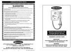
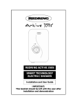
570
Pumped Electric Shower
Installation instructions & User guide
IMPORTANT: This booklet should be given to the customer after installation and demonstration.
WARNING: Under no circumstances should this unit be connected to the mains cold water supply.
Thank you for choosing a quality 'Redring'
product manufactured in Peterborough, England.
CONTENTS
Information for the user
Important Safety Instructions
How to use your 'Redring' shower
How your 'Redring' shower works
How to maintain your 'Redring' shower
What to do if things go wrong
Additional accessories
Information for the installer
Fixing the shower to the wall
Plumbing
Electrical
Guarantee
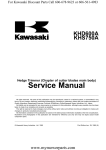
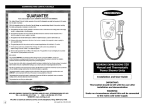
Knob 'A'
Page
Overheat Light
2
2
3
4
4
9
6
7
8
12
IMPORTANT SAFETY
INSTRUCTIONS
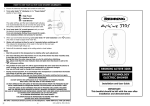
1. The Redring Expressions 570 pumped
electric shower is designed to heat and
boost the flow of stored domestic cold
water, which is gravity fed from a static
cold water cistern.
Under no circumstances should this unit
be connected directly to the mains cold
water supply.
2. The cold water cistern should have a
minimum capacity of 114 Litres (25 gallons).
There must be a minimum head of water of
8.0 cm (3") and a maximum head of 10
Metres (33ft) between the bottom of the cold
water cistern and the top of the shower unit.
Under no circumstances should any of
the pipework supplying the shower unit
rise above the level of the bottom of the
cold water cistern.
3. WARNING! DO NOT SWITCH THE
SHOWER ON IF YOU SUSPECT IT OF
BEING FROZEN. WAIT UNTIL YOU ARE
SURE IT HAS THAWED OUT.
2
Diagram 1
Power On Light
Knob 'B'
HOW TO USE YOUR 'REDRING'
SHOWER
1. Ensure the electricity and water supplies are
turned on to the unit.
2. Your shower has 2 power settings selected
by turning knob 'A'. The most popular setting
is 'HIGH' indicated by '• high power'.
There is also a 'LOW' power option indicated
by '• low power'. (See note 7).
For this example turn knob 'A' to
'• high power'.
3. To start the shower turn knob 'B'
anti-clockwise. Water will start flowing at
around 15º knob rotation (position 10 on the
temperature scale) and the motor will switch
on at around 30º (position 9 on the
temperature scale). The 'power on' light will
illuminate at this stage.
4. Continue turning knob 'B' anti-clockwise
until the required temperature of water is
achieved, allowing time for the temperature of
the water to stabilise.
Note: It is advisable to test the temperature
of the water with your hand before stepping
under the showerhead.
5. If the water is too hot increase the flow of
water by turning knob 'B' anti-clockwise
to a lower number on the temperature scale.
6. If the water is too cold decrease the flow of
water by turning knob 'B' clockwise
to a higher number on the temperature scale.
7. The '• low power' setting of knob 'A'
reduces the power giving a cooler shower or
the option of reduced water flow. This option
is mainly for summer usage and if this is used
then knob 'B' must be re-adjusted.
8. When you have finished showering turn knob
'B' fully clockwise to the '• Stop' position.
The motor will switch off and water will stop
flowing. The 'POWER ON' light will also
switch off.
9. Switch off the electricity at the ceiling switch
or local isolator.
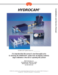
Diagram 2
10. During normal operation if an overheated
water temperature is sensed by the shower
the thermal cut-out will switch off the power
to the heating elements. The 'overheat' light
will illuminate to provide a visual indication that
this has taken place. Water will continue to
flow and as the water temperature falls the
heating elements will be switched back on. If
the 'overheat' light continues to cycle turn
knob 'B' anti-clockwise to a lower number on
the temperature scale and check that the
handset does not require de-scaling (see
page 4). If the 'overheat' light still continues
to cycle turn knob 'A' to the '• low power'
setting (knob 'B' will need adjusting).
If the shower is operated after it has recently
been used the 'overheat' light may illuminate
for a few seconds. This indicates there is still
some hot water left in the shower. Either, wait
a few moments for the light to go out or turn
knob 'B' anti-clockwise to a lower number on
the temperature scale.
WARNING! DO NOT SWITCH THE
SHOWER ON IF YOU SUSPECT IT OF
BEING FROZEN. WAIT UNTIL YOU ARE
SURE IT HAS THAWED OUT.
HOW YOUR 'REDRING' SHOWER
WORKS
Your Redring shower is designed for
convenience, economy and safety of use.
1. Water is heated instantaneously as it flows
over the heating elements in the copper
cylinder assembly.
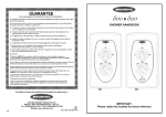
2. The required
water temperature
is achieved
Diagram 3
by adjusting the
rate of water
flow. Diagram 3
shows the
principle
involved in
relating
temperature rise to flow rate. The higher the
water flow the lower the temperature rise and
vice versa. The temperature of the water
supplied from the cold water storage cistern
can vary considerably throughout the year
from as low as 5º to as high as 30ºC. This
means that in the winter, the flow rate will be
less than in the summer to achieve the same
outlet temperature. In summer the '• low
power' setting may give adequate hot water.
3. Your shower incorporates a pump which
boosts the incoming water pressure to a level
more suitable for showering. The motor is
controlled by a switch connected to knob 'B'.
4. The heaters are only switched on when
sufficient water is flowing. This will happen
when the motor is switched on, and is done
automatically with a switch which works on
water pressure.
5. The water is turned on and off by a tap that is
built into the shower.
6. If the water supply falls below a set limit, the
pressure switch will operate and switch off the
power to the elements.
7. As a further safeguard, a thermal cut-out
switches the power off if the water
3
temperature climbs above a set limit and the
'overheat' light will come on. This cut-out
which gives an audible click, may also
operate due to residual heat when the shower
is switched off. It will reset itself if cold water
is run through the shower for 10 to 20
seconds and the 'overheat' light will go out.
8. A pressure relief device is fitted to safeguard
against extreme abuse conditions.
9. There are three defined plate spray settings
adjustable by rotating the spray plate (see
diagram 4). If desired many combinations
between the 3 can be achieved.
Diagram 4
a)
'CASCADE'
(inner/outer)
b)
'SURF'
(outer spray
only)
c)
'SPORT'
(inner spray
only)
Diagram 5
The spray head rotates
through approximately 140o
IN ORDER TO MAINTAIN THE
PERFORMANCE OF YOUR
SHOWER YOU MUST CLEAN
THE SHOWERHEAD.
4
HOW TO MAINTAIN YOUR
'REDRING' SHOWER
All water contains particles of lime which build up
in the showerhead and unit reducing the
performance. It is therefore important to clean the
showerhead by regularly dipping it in a suitable
de-scaling solution. The frequency of this will vary
from weekly to quarterly.
Check the srayplate is then free to rotate to give
the three setting. In some winter conditions,
when incoming water from the cold water storage
cistern is particularly cold it may be necessary to
select the inner or outer spray pattern only. This
will ensure correct operation of the shower with a
slightly lower water flow rate.
NOTE:
After use it is normal for some water to drip from
the shower head for a few moments.
Cleaning
It is recommended that the shower unit and
accessories are cleaned using a soft cloth.
DO NOT use powerful abrasive or solvent
cleaning fluids. It is advisable to switch off the
shower at the isolating switch to avoid the
shower accidently switching on.
WHAT TO DO IF THINGS GO
WRONG
Self Help
If the performance of the shower does deteriorate
in service make the following checks before
calling out the contractor. Any one of these
simple adjustments could restore the
performance.
a) Water too
HOT
Increase water flow by
adjusting the temperature
control (knob B) anti-clockwise
to a lower number on the
temperature scale.
Clean the showerhead.
Switch power to '• low
power' setting .
Select outer or combination
spray pattern.
Increase pressure of water
supply e.g. fully open service
valve.
Check hose is not kinked
restricting the water flow.
b) Water too
COLD
c) Pump
operates but
no water is
delivered
d) Pump fails
during
shower
Check power is on (indicated
by 'power on' light).
Decrease water flow by
adjusting the temperature
control (knob 'B') clockwise to
a higher number on the
temperature scale.
Switch power to '• high
power' setting.
Select inner or outer spray
patterns only .
Water starvation. Stop pump
immediately by turning knob
'B' fully clockwise to the
'• Stop position'. Check the
cold water cistern is full.
Ensure water supply pipe is not
blocked or air-locked. Re-prime
shower unit (see
commissioning) with power to
shower switched off.
Professional Service
If the previous checks fail to restore the
performance, you should seek professional help.
The person who installed the shower is probably
the best one to repair it and is certainly the
person to contact if you have a problem in the
guarantee period.
The following additional checklist is provided for
the benefit of the qualified serviceman.
Warning! Switch off the electricity at the
isolating switch before removing the cover
to make checks.
a) Water too
HOT
Water flow restricted by
blockage in filter. Switch off
water at service valve and fully
isolate electricity supply.
Remove shower from wall.
Remove filter (see diagram 9)
clean and replace.
b) Water too
COLD
Check circuit through thermal
cut-out.
Check circuit through
microswitches on the pressure
switch.
Check each element circuit.
Check tightness of electrical
connections.
c) Pump fails
to operate
If the 'power on' light is lit,
possible motor failure. Replace
motor.
If the 'power on' light remains
off, check motor switch.
Replace if necessary.
d) Pump
operates but
no water is
delivered
Faulty motor switch (short
circuit). Replace.
Incorrect alignment of motor
switch camdrive. In off position,
the alignment marks on the
cam drive (see diagram 2)
should be centred about motor
switch actuator.
Water flow restricted by
blockage in filter. Switch off
water and remove shower from
wall. Remove filter (see
diagram 9), clean and replace.
Thermal trip inside motor has
operated. Wait for motor to
cool down (approx 30 mins).
e) Spray
Clean showerhead (see page
pattern poor 4) and flush heater.
Select an outer/inner spray
pattern.
f) Water takes
longer to
heat up
Thermal cut-out has operated
after previous use ('overheat'
light is on).
Switch power to
'• high power' setting.
f) Water goes
cold while
using
shower
Thermal cut-out has operated
('overheat' light is on) Wait for
cut-out to reset.
Check power is on (indicated
by 'power on' light).
f) Broken parts Please contact our spares
department on 01733 456700.
5
e) Water leaks
from burst
pressure
relied valve
Check for cause of high
pressure and remove it.
Blockage on outlet i.e: blocked
spray plate etc. Replace the
pressure relief disc.
REDRING AFTER SALES SERVICE
We offer a technical advisory service on the
telephone to contractors and other customers
with problems in the field.
Ring 0870 9000 430 (Normal Office Hours)
Spare parts can be supplied against any VISA or
Access cards.
Ring 0870 9000 420 (Normal Office Hours)
Remember to quote the exact type of shower, as
written on the front of the shower and on this
leaflet. It may also be of use to have a note of the
Catalogue Number as stated on the rating plate
inside the shower.
A) Fixing the shower to the wall
The Redring Expressions 570 Pumped
Electric Shower is fitted with a motor and
some mechanical noise can be expected
when in use. The type of wall structure will
affect the noise levels. Solid walls will
provide quieter operation than panel or stud
partition walls.
Diagram 7a
Diagram 7b
Diagram 6
Service Valve
1ft (0.3 m) max,
Rising Main
Cold Water
Cistern
3", 8cm min, 33ft (10 m) max,
recommended heights between
bottom of cold water cistern
and top of shower unit.
6'6" (2 m)
av. height
from top of
riser rail to
base of bath
or cubicle.
INSTALLATION INSTRUCTIONS
The installation should be done by qualified
personnel and checked by the Electricity Board.
WARNING: DO NOT INSTALL THE SHOWER
IN A ROOM WHERE IT MAY BE SUBJECT TO
FREEZING.
We recommend that the installation is done in the
following sequence :A) Fixing the shower to the wall.
B) Plumbing.
C) Electrical connections.
6
1. Place the riser rail at the height
recommended in diagram 7b and mark its
position.
2. Position the heater so that the sides of the
unit are vertical and the top is level with, or up
to 0.3m (1ft) maximum below the top of
the riser rail. Choose a flat piece of wall to
avoid the possibility of distorting the backplate
thus making the front cover a poor fit.
3. Adjust the positions to get the most
convenient arrangement taking the following
into account : a) The possible need to use the handset
over the sink for hair washing etc.
b) The heater must not be mounted in the
direct spray from the handset.
c) The handset must not be able to come into
contact with the used water in the cubicle,
bath or basin. If it can, even after the hose
has been retained by the hose retainer (see
diagram 12), then a vacuum breaker must be
fitted. It should be noted that these devices
are liable to minor leakage so they must be
positioned so that any drips are not
detrimental.
4. Fix the riser rail with screws provided.
The fixing holes at the base of the brackets
will be revealed by removing the plastic fronts.
Assemble as shown in diagram 12.
5. Decide the position of the electrical cable to
the unit. If top or bottom entry is chosen,
carefully cut away the relevant walls of the
backplate as shown in diagram 6.
6. Decide the position of the cold water pipe into
the unit. If top or bottom entry is chosen,
carefully cut away the relevant walls of the
backplate as shown in diagram 6. If bottom
entry is chosen refer to note 4 in the plumbing
section.
7. If you have not yet done so, remove the front
cover (complete with knobs) by undoing the
retaining screws at the top and bottom of the
unit. Your shower is provided with three fixing
positions in the backplate (see diagram 6).
The top fixing hole is a key-hole slot and
should be marked and drilled first. Tighten top
screw with head protruding about 10mm from
wall and hook the backplate over the screw
head. This allows for correct and accurate
alignment of your shower before marking and
fixing the bottom positions. You may not wish
to tighten up the screws at this stage as the
holes are elongated to allow for adjustment
after other connections have taken place.
B) Plumbing
WARNING : - UNDER NO CIRCUMSTANCES
SHOULD THIS UNIT BE CONNECTED TO
THE MAINS COLD WATER SUPPLY.
The heater should be connected to a cold water
supply gravity fed from a static cold water cistern
with a minimum capacity of 114 litres (25 galls).
There must be a minimum head of water of 8 cm
(3") and a maximum head of 10 metres (33ft).
It is strongly advised to install the shower unit
using an independent supply from the cold water
storage cistern. The shower would then be totally
unaffected by other draw off points elsewhere in
the system and thus the pressure and
temperature will remain more stable. Therefore
the cold water supply should be taken directly
from the cold water cistern.
Under no circumstances should any of the
pipework supplying the shower unit rise
above the level of the bottom of the cold
water cistern.
Before connecting the pipework to the shower
ensure that the pipework is flushed out.
1. It is recommended that a water council listed
isolating valve is fitted between the cold water
storage cistern and the shower unit. This will
allow the shower unit to be serviced without
turning off the cold water at the water stop
valve and draining the cold water cistern.
2. 15mm copper pipe should be used. Ensure
all burrs have been removed from the
pipes before inserting into the push fit
inlet ports. Diagram 8 illustrates the correct
procedure for inserting and removing the
pipes from the inlet ports.
Take care to line up the inlet pipe correctly
with the inlet port to avoid straining the
internal 'O' ring seal.
DO NOT use solder fittings within 300mm
of plastic fittings.
3. To maintain the optimum performance, the
pipe runs should be kept as short as
possible, using sweeping bends rather than
right angles or restrictive fittings.
4. If bottom entry has been chosen, the inlet
port must be rotated through 1800 into the
required position. To do this unscrew the side
section from the shower unit (see diagram 6).
Rotate inlet connection ensuring that a snug
fit into the cradle is achieved, replace side
section retaining screw and remove the side
section and tighten screw.
5. With an isolating valve connecting, flush the
pipework through to remove particles
etc. before making the final connection to the
shower. A blockage in the waterways
(particularly the spray rings and filter) will
prevent the shower unit working properly.
7
6. The shower is designed to have an open
outlet and should only be used with Redring
recommended fittings.
WARNING: DO NOT FIT A TAP ON THE
SHOWER OUTLET. TAKE CARE TO AVOID
RESTRICTING THE OUTLET OF THE
PRESSURE RELIEF DEVICE. (SHOWN IN
DIAGRAM 2).
Diagram 8
Simply push
in tube to
attach
A
Tube is
secured in
position
B
Push in
collet to
release tube
C
2. Cable Sizes
Model
Exp. 570
(8.5 kW)
Exp. 570 (9.5 kW)
Cable Sizes
Fuse Type
2
6mm
40 A Cartridge Fuse
Type 'A' MCB
10mm2
10mm2
45 A Cartridge Fuse
45 A Cartridge Fuse
Expressions 570 9.5/8.7kW, 240/230V, version
may be able to use 6mm2 cable if BS 7671:
Method 1 (clipped direct) is used. The maximum
cable run for all models above will depend upon
site conditions.
REMEMBER TO UPRATE THE CABLE IF IT RUNS
IN THERMAL INSULATION IN A LOFT.
3. In order to provide a means of isolation, the
heater MUST BE permanently connected to
the electricity supply through a double pole
linked switch with a contact gap of 3mm
mounted in a convenient position. We
recommend ceiling switches.
4. Cut back cable as in diagram 10, connect
cable to terminal block making sure that all the
retaining screws are VERY tight and that no
cable insulation is trapped under the screws.
Diagram 9
C) Electrical
The electrical installation must be in accordance
with current BS. 7671 (I.E.E. regulations) and/or
local regulations.
1. The shower is designed for a single phase
A.C. electrical supply of:
Model
Expressions 570
(8.5 kW)
Expressions 570
(9.5 kW)
Variant
8.5 / 7.8 kW
8.5 kW
9.5 / 8.7 kW
9.5 kW
Rated Voltage
240 / 230 V
230 V
240 / 230 V
230 V
Please check the rating plate on the unit to see
what details apply to your unit.
8
SCHEMATIC
WIRING
DIAGRAM
WARNING: FAILURE TO COMPLY WITH
THESE INSTRUCTIONS COULD RESULT IN A
FAILURE OF THE TERMINAL BLOCK.
5. A dual position cable clamp is provided. For
top cable entry use retaining bar in horizontal
position supplied. For bottom cable entry
rotate retaining bar to the angled position.
6. WARNING: THIS APPLIANCE MUST BE
EARTHED.
7. The earth
8mm
10mm
continuity
5mm
conductor of
Live
10mm
the electrical
Earth
Neutral
installation
33mm
MUST BE
effectively
Diagram 10
connected
electrically to all exposed parts of the
appliances and services in the room in which
the water heater is to be installed in conformity
with the current BS. 7671 (I.E.E. wiring
regulations).
FINAL INSTALLATION PROCEDURE
AND COMMISSIONING
WARNING : DO NOT SWITCH ON THE
ELECTRICITY SUPPLY UNTIL THE
FOLLOWING PROCEDURE HAS BEEN
COMPLETED. FAILURE TO DO SO COULD
CAUSE THE PUMP TO RUN DRY AND
INVALIDATE THE GUARANTEE.
1. Fit the front cover back into position, ensuring
that both the control knobs are correctly
aligned with the flow valve and power selector.
Secure with top and bottom screws.
2. Fit hose and prime the shower first without the
handset to flush out any remaining debris. To
prime the shower ensure that the electricity
supply is switched off. Turn control knob 'B'
fully anti-clockwise. Water should start to flow
with motor switched off allowing all the air to
be purged out of the shower unit.
c) Power selection operates in both positions,
giving a change in water temperature
d) Check again for leaks
e) That the holes in the spray plate are not
blocked
f) That the motor turns off and water stops
flowing in the 'STOP' position
3. DEMONSTRATE OPERATION TO THE USER
Please leave these instructions with the user
for future reference.
ADDITIONAL ACCESSORIES
Cat. No.
White 2 metre shower hose
1 metre riser rail
Water control tap
Shower de-scaling powder
Curtain and rail pack
Curtain and rail pack with non
slip bath mat
83-593529
83-593530
93-792452
95-711015
83-792802
83-792801
Spare parts/accessories can be supplied
against any Visa or Access cards from
Redring Sales 01733 456700.
INLET ASSEMBLY SHOWING FILTER
POSITION
Diagram 11
It may be necessary to lower the hose
below the level of the shower unit whilst
priming.
Stop water flow by turning knob 'B' fully
clockwise. Attach handset, switch on electrical
supply and then operate the shower as on
page 2 and check–
a) That the water gets to a satisfactory
temperature
b) Water flow can be adjusted by knob 'B'
9
ASSEMBLY OF RISER RAIL, HANDSET
AND SOAP DISH
Diagram 12
Additional
knock out
fixing slot if
required
Removable
insert in soap
dish for ease
of cleaning
10
Locating
Key
Guarantee
We, GDA Applied Energy, guarantee that should this instant water heater prove to be
defective by reason of faulty workmanship or material within 24 months (12 months
outside the U.K.) of the date of purchase or commencement of hire purchase we will
replace the defective parts FREE OF CHARGE on condition that:
•
The appliance has been correctly installed and used only on the supply
circuit or voltage stamped on the rating plate.
•
The appliance has been used in accordance with these instructions and has
not been tampered with or otherwise subjected to misuse, neglect or accident.
•
The appliance has not been taken apart, modified or repaired except by a
person authorised by us.
•
Evidence of the date of purchase in the form of an invoice, receipt (or hire
purchase documents) is included with the appliance if returned under guarantee.
'This Guarantee does not affect your statutory rights'
Full details of Terms and Conditions of Guarantee are available on request from : ®
GDA APPLIED ENERGY LTD, MORLEY WAY, PETERBOROUGH PE2 9JJ.
TEL: +44(0)1733 456789 FAX: +44 (0)1733 310606
Website : www.redring.co.uk
559-2334-01 A
12