1
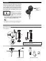
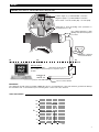
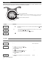
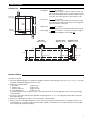
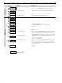
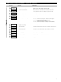
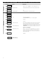
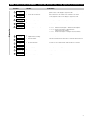
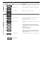
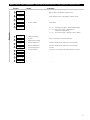
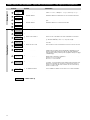
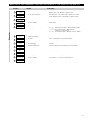
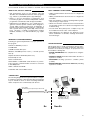
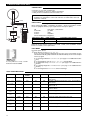
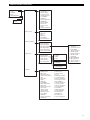
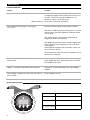
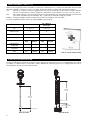
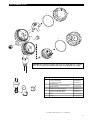
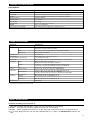
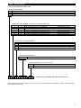
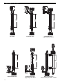
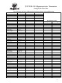
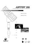
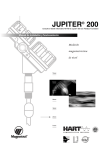
JUPITER 200
®
Refer to bulletin 46-649 for Jupiter® 200 with Fieldbus Foundation
Installation and Operating Manual
Magnetostrictive
Level
Measurement
7xxx
6xxx
5xxx
4xxx
3xxx
2xxx
1xxx
I VE GOT
ABILITY
®
FE T Y I
EGRITY
NT
SA
VE L
LE
UNPACKING
Unpack the instrument carefully. Make sure all components
have been removed from the foam protection. Inspect all
components for damage. Report any concealed damage to
the carrier within 24 hours. Check the contents of the carton/crates against the packing slip and report any discrepancies to Magnetrol. Check the nameplate model number
(Model number/approvals as per inserted separate sheet) to
be sure it agrees with the packing slip and purchase order.
Check and record the serial number for future reference
when ordering parts.
Amplifier nameplate:
- partnumber
- amplifier
- serial n°
- temperature/pressure
- approval data
These units are in conformity with the
provisions of:
1. The EMC Directive: 89/336/EEC.
0038
The units have been tested to EN
0344
61000-6-4/2001 and EN 61000-62/2001.
2. Directive 94/9/EC for Equipment or protective system for
use in potentially explosive atmospheres. EC-type examination certificate number ISSEP06ATEX024X (intrinsic
safe units) or ISSEP06ATEX010 (EEx d units).
3. The PED directive 97/23/EC (pressure equipment directive). Safety accessories per category IV module H1.
MOUNTING
External Mount Model
Note: if ordered from the factory with the Magnetic Level Indicator the transmitter will be attached to the gauge and configured
for the application.
Strap
CAUTION: do not rotate the housing. This may cause
damage to the sensor cables.
Guide Tab
Direct Insertion Model
Up
min 2"
Bottom view
Float attachment detail
2
WIRING
CAUTION: power must be switched OFF before wiring the unit.
–
–
LOOP
CURRENT
Positive supply to (+) terminal/HART connection
Negative supply to (-) terminal/HART connection
min 12 V DC – max 28,4 V DC (Exi) - 32 V DC (Exd)
+
®
IS
IS
Shield wire to green grounding screw (resistance to
ground must be < 1 Ω).
Use certified flameproof cable
gland(s) and cable for Explosion
proof area.
100 %
0%
Customer supplied
local current meter
Ex
Ex
Ex
Non Ex
Non Ex
Non Ex
Galvanic Barrier:
Intrinsically safe units:
max 28,4 V DC @ 94 mA
Not needed for General Purpose / explosion proof
models.
ANALOG I/O
or
DIGITAL I/O
(only for units with HART)
Do not connect shield
IMPORTANT:
The shield wire should only be grounded at ONE side only. It is recommended to connect the shield to ground in the field (at
the transmitter side - as shown above) but connecting in the control room is also allowed.
LOOP RESISTANCE
1200
20.5 mA
1000
800
Ω
620
600
400
200
24 VDC
0
11
0
10
20
30
40 VDC
3
CONFIGURATION
NOTE: When connected to an approved barrier, the intrinsically safe electronics of the Jupiter® 200 allow to remove
the covers with power switched on – even if the area is known to be hazardous
2 line – 8 characters LCD
Default display cycles every 8 s through Status «STATUS» / Level «LEVEL»
/ % output «% OUTPUT» / Loop «LOOP». Level not displayd for FF units.
Up/Down and Enter pushbuttons
Display
Comment
:
The last character on the first line of the display changes to «!». This sign confirms that the values/choices of the second line can be modified via the and
push buttons.
Units!
cm
Press
Units!
cm
Press
* Scroll through the choices or increase/decrease the values on the second line
of the display by and pushbuttons.
pushbutton.
* Accept values/choices as selected by
Units
cm
Press
Scroll through the menu.
PASSWORD
ACTION/
COMMENT/
Ent Pass
0
Display shows «0»
Factory default setting
Data is not protected
Ent Pass!
1
Press
and last character changes into «!»
Enter your personal password with and
(any value between 1 and 255)
Press
to confirm
Setting password
Press
and enter old password
and last character changes into «!»
Press
Enter your new password with and
(any value between 1 and 255)
Press
to confirm
Changing password
Display shows an encrypted value, enter your password
or call Magnetrol for assistance to recoop your password
if necessary
Data is protected by a valid
Password
DISPLAY
New Pass
4096
NOTE: Password protection is activated when after 5 minutes no keystrokes are sensed.
4
CONFIGURATION
TERMINOLOGY
20 mA Level
(100%-point)
Float 1
Level Offset
=
cm or inches
The offset is the distance between reference point (e.g.
bottom of tank) and end of probe. From the reference point
both 4 mA and 20 mA levels are calibrated. When offset is
set at zero, the end of the probe is the reference point.
4 mA Level
=
cm or inches
or zero level point, is measured from the reference point.
The unit with SIL enhanced electronics has a diagnostic
zone at the bottom of the probe.
Float 2
Probe
Length
Probe
Length
20 mA Level =
cm or inches
or 100 % level point, is measured from the reference point.
4 mA Level
(0%-point)
Float 1
Float 2
cm or inches, record the exact probe length as
Probe length =
printed on the nameplate: 2xx-xxx-xxM-xxx
Level offset
Reference
point
No offset
(Offset at 0 cm)
100 %
20 mA = 75 cm
0%
4 mA = 15 cm
Positive offset
(Offset at 10 cm)
Negative offset
(Offset at -15 cm)
20 mA = 85 cm
20 mA = 60 cm
4 mA = 25 cm
4 mA = 0 cm
75 cm
15 cm
10 cm
BEFORE STARTING
Start from run mode:
1. Select the desired language for configuration: English or Spanish in the language screen (22 or 25) «language». Scroll up
for quickly reaching the language selection screen.
2. Define type of measurement:
a. Level only
(pages 6 & 7)
b. Interface only
(pages 8 & 9)
(pages 10 & 11)
c. Interface and Level
d. Level and Interface
(pages 11 & 12)
Scroll down until the screen reads «MeasType». The unit will now show only the applicable screens for the selected type
of measurement.
3. Scroll one screen down and select the applicable engineering unit in «Units», all configuration values will be entered in
that engineering unit.
4. Refer to the configuration procedure of the selected type of measurement.
5. Refer to page 14 for all hidden diagnostic screens. These screens allow the advanced user to configure the unit for special applications or to troubleshoot the unit in the field. It is NOT recommended to access this toolset without proper guidance or having followed proper training.
5
MENU: STEP BY STEP PROCEDURE – Jupiter 200: Level only – Loop signal (PV) is Level
Configuration
Run mode
Screen
Action
1
*Status*
*Level*
*%Output*
*Loop*
Transmitter Display
Transmitter default values cycle every 8 seconds. Status «Status»,
Volume «Volume», % Output «% Output», and Loop «Loop».
2
Level
xxx.xx
Transmitter Display
Transmitter displays Level Value in selected engineering units.
3
%Output
xx.xx
Transmitter Display
Transmitter displays % Output measurement derived from 20 mA
span.
4
Loop
xx.xx mA
Transmitter Display
Transmitter displays Loop measurement (mA).
5
MeasType
(select)
Select the type of measurement
Select level «Lvl only».
6
Units
(select)
Select units for level
cm «cm» or inches «inches».
7
Probe Ln
xxx.xx
Enter the exact length of
probe
Enter as per the 3 last digits of the probe partnumber on the nameplate:
From 15 cm up to 999 cm
e.g. 242-D111-AAM-280, enter «280» cm probe length.
8
Set 4mA
xxx.xx
Enter the PV for 4 mA
Enter 4 mA level point, measured from reference point in selected
level units.
9
Set 20mA
xxx.xx
Enter the PV for 20 mA
Enter 20 mA level point, measured from reference point in selected
level units.
10
Lvl Ofst
xxx.xx
Enter the offset value
When entering configuration values from the end of the probe is
cumbersome, an offset can be introduced to determine a new
reference point. This reference point can be either below the
probe (positive offset) or at the probe (negative offset). See page
5 “Terminology”.
11
Damping
xx.x s
Enter the damping factor.
A Damping factor (1-25 seconds) may be added to smooth a noisy
display and/or output due to turbulence.
Below 15 s = 0,1 s increments.
Above 15 s = 1 s increments.
12
Fault
(Select)
Enter the value for error.
Select «3.6 mA», «22 mA» or hold last value «HOLD». In case of
loop failure, error signal will follow the failing trend; meaning the unit
will show 3.6 mA when the reviewed loop current by the device is
found too low. The unit will show 22 mA in case the reviewed loop
current is found too high.
13
Poll Adr
xx
Enter HART ID number.
Select a HART poll address (0-15). Enter 0 for a single transmitter
installation.
= Quick Start up
6
Comment
MENU: STEP BY STEP PROCEDURE – Jupiter 200: Level only
Diagnostics
Screen
Action
Comment
14
Trim 4
xxxx
Fine tune the 4 mA point.
Attach a mA meter to the output. If the output does not equal 4.0 mA,
adjust the value on the display to equal 4.00 mA.
15
Trim 20
xxxx
Fine tune the 20 mA point.
Attach a mA meter to the output. If the output does not equal
20.0 mA, adjust the value on the display to equal 20.00 mA.
16
Loop Tst
xx.x mA
Enter a mA output value.
Set mA Output to any given value to perform loop test.
17
Deadband
xx.x
None, do not adjust.
Factory setting.
18
Snsr Mnt
(select)
Select the type of mounting.
«MLI Top» External mount Jupiter – Top mounted Jupiter
«MLI Bot» External mount Jupiter – Bottom mounted Jupiter
«Dir Near» Direct mount Jupiter – NPT, BSP and
Flanged ≤ 600 lbs / PN160
«Dir Ext» Direct mount Jupiter – Flanged ≥ 900 lbs / PN250
19
Trim Lvl
xx.xx
Enter value
to adjust level reading.
Allows to compensate for a fixed level deviation.
20
F1 Cnts
xxxx
Diagnostic display.
Shows time of flight from the start pulse to reflected signal from level.
21
New Pass
xxx
Enter new password.
Use arrows to select desired value. Values between 0 and 255.
22
Language
(select)
Select language
Select «English» or «Espagnol».
23
JupiterHT
Ver 3.0A
None, do not adjust.
Factory setting. «Ver» refers to software version.
24
DispFact
(select)
Advanced diagnostics.
See page 14.
7
MENU: STEP BY STEP PROCEDURE – Jupiter 200: Interface only – Loop signal (PV) is Interface Level
Configuration
Run mode
Screen
Action
1
*Status*
*IfcLevel*
*%Output*
*Loop*
Transmitter Display
Transmitter default values cycle every 8 seconds. Status «Status»,
Volume «Volume», % Output «% Output», and Loop «Loop».
2
IfcLevel
xxx.xx
Transmitter Display
Transmitter displays Interface Value in selected engineering units.
3
%Output
xx.xx
Transmitter Display
Transmitter displays % Output measurement derived from 20 mA
span.
4
Loop
xx.xxx mA
Transmitter Display
Transmitter displays Loop measurement (mA).
5
MeasType
(select)
Select the type of measurement
Select Interface «Ifc only».
6
Units
(select)
Select units for level
cm «cm» or inches «inches».
7
Probe Ln
xxx.xx
Enter the exact length of
probe
Enter as per the 3 last digits of the probe partnumber on the nameplate:
From 15 cm up to 999 cm
e.g. 242-D111-AAM-280, enter «280» cm probe length.
8
Set 4mA
xxx.xx
Enter the PV for 4 mA
Enter 4 mA level point, measured from reference point in selected
level units.
9
Set 20mA
xxx.xx
Enter the PV for 20 mA
Enter 20 mA level point, measured from reference point in selected
level units.
10
Lvl Ofst
xxx.xx
Enter the offset value
When entering configuration values from the end of the probe is
cumbersome, an offset can be introduced to determine a new
reference point. This reference point can be either below the
probe (positive offset) or at the probe (negative offset). See page
5 “Terminology”.
11
Damping
xx.x s
Enter the damping factor.
A Damping factor (1-25 seconds) may be added to smooth a noisy
display and/or output due to turbulence.
Below 15 s = 0,1 s increments.
Above 15 s = 1 s increments.
12
Fault
(Select)
Enter the value for error.
Select «3.6 mA», «22 mA» or hold last value «HOLD». In case of
loop failure, error signal will follow the failing trend; meaning the unit
will show 3.6 mA when the reviewed loop current by the device is
found too low. The unit will show 22 mA in case the reviewed loop
current is found too high.
13
Poll Adr
xx
Enter HART ID number.
Select a HART poll address (0-15). Enter 0 for a single transmitter
installation.
= Quick Start up
8
Comment
MENU: STEP BY STEP PROCEDURE – Jupiter 200: Interface only – Loop signal (PV) is Interface Level
Diagnostics
Screen
Action
Comment
14
Trim 4
xxxx
Fine tune the 4 mA point.
Attach a mA meter to the output. If the output does not equal 4.0 mA,
adjust the value on the display to equal 4.00 mA.
15
Trim 20
xxxx
Fine tune the 20 mA point.
Attach a mA meter to the output. If the output does not equal
20.0 mA, adjust the value on the display to equal 20.00 mA.
16
Loop Tst
xx.x mA
Enter a mA output value.
Set mA Output to any given value to perform loop test.
17
Deadband
xx.x
None, do not adjust.
Factory setting.
18
Snsr Mnt
(select)
Select the type of mounting.
«MLI Top» External mount Jupiter – Top mounted Jupiter
«MLI Bot» External mount Jupiter – Bottom mounted Jupiter
«Dir Near» Direct mount Jupiter – NPT, BSP and
Flanged ≤ 600 lbs / PN160
«Dir Ext» Direct mount Jupiter – Flanged ≥ 900 lbs / PN250
19
Trim Ifc
xx.xx
Enter value
to adjust interface reading.
Allows to compensate for a fixed level deviation.
20
F1 Cnts
xxxx
Diagnostic display.
Shows time of flight from the start pulse to reflected signal from level.
21
New Pass
xxx
Enter new password.
Use arrows to select desired value. Values between 0 and 255.
22
Language
(select)
Select language
Select «English» or «Espagnol».
23
JupiterHT
Ver 3.0A
None, do not adjust.
Factory setting. «Ver» refers to software version.
24
DispFact
(select)
Advanced diagnostics.
See page 14.
9
MENU: STEP BY STEP PROCEDURE – Jupiter 200: Interface and Level – Loop signal (PV) is Interface Level
Configuration
Run mode
Screen
Action
1
*Status*
*Level*
*%Output*
*Loop*
Transmitter Display
Transmitter default values cycle every 8 seconds. Status «Status»,
Volume «Volume», % Output «% Output», and Loop «Loop».
2
IfcLevel
xxx.xx
Transmitter Display
Transmitter displays Interface Level Value in selected engineering
units.
3
%Output
xx.xx
Transmitter Display
Transmitter displays % Output measurement derived from 20 mA
span.
4
Loop
xx.xx mA
Transmitter Display
Transmitter displays Loop measurement (mA).
5
Level
xxx.xxx
Transmitter Display
Unit displays locally top liquid level.
6
MeasType
(select)
Select the type of measurement
Select Interface and level «Ifc&Lvl».
7
Units
(select)
Select units for level
cm «cm» or inches «inches».
8
Probe Ln
xxx.xx
Enter the exact length of
probe
Enter as per the 3 last digits of the probe partnumber on the nameplate: From 15 cm up to 999 cm
e.g. 242-D111-AAM-280, enter «280» cm probe length.
9
Set 4mA
xxx.xx
Enter the PV for 4 mA
Enter 4 mA level point, measured from reference point in selected
level units.
10
Set 20mA
xxx.xx
Enter the PV for 20 mA
Enter 20 mA level point, measured from reference point in selected
level units.
11
Lvl Ofst
xxx.xx
Enter the offset value
When entering configuration values from the end of the probe is
cumbersome, an offset can be introduced to determine a new
reference point. This reference point can be either below the
probe (positive offset) or at the probe (negative offset). See page
5 “Terminology”.
12
Damping
xx.x s
Enter the damping factor.
A Damping factor (1-25 seconds) may be added to smooth a noisy
display and/or output due to turbulence.
Below 15 s = 0,1 s increments.
Above 15 s = 1 s increments.
13
Fault
(Select)
Enter the value for error.
Select «3.6 mA», «22 mA» or hold last value «HOLD». In case of
loop failure, error signal will follow the failing trend; meaning the unit
will show 3.6 mA when the reviewed loop current by the device is
found too low. The unit will show 22 mA in case the reviewed loop
current is found too high.
14
Poll Adr
xx
Enter HART ID number.
Select a HART poll address (0-15). Enter 0 for a single transmitter
installation.
= Quick Start up
10
Comment
MENU: STEP BY STEP PROCEDURE – Jupiter 200: Interface and Level – Loop signal (PV) is Interface Level
Diagnostics
Screen
Action
Comment
15
Trim 4
xxxx
Fine tune the 4 mA point.
Attach a mA meter to the output. If the output does not equal 4.0 mA,
adjust the value on the display to equal 4.00 mA.
16
Trim 20
xxxx
Fine tune the 20 mA point.
Attach a mA meter to the output. If the output does not equal
20.0 mA, adjust the value on the display to equal 20.00 mA.
17
Loop Tst
xx.x mA
Enter a mA output value.
Set mA Output to any given value to perform loop test.
18
Deadband
xx.x
None, do not adjust.
Factory setting.
19
Snsr Mnt
(select)
Select the type of mounting.
«MLI Top» External mount Jupiter – Top mounted Jupiter
«MLI Bot» External mount Jupiter – Bottom mounted Jupiter
«Dir Near» Direct mount Jupiter – NPT, BSP and
Flanged ≤ 600 lbs / PN160
«Dir Ext» Direct mount Jupiter – Flanged ≥ 900 lbs / PN250
20
Trim Lvl
xx.xx
Enter value
to adjust level reading.
Allows to compensate for a fixed level deviation.
21
Trim Ifc
xx.xx
Enter value
to adjust interface reading.
Allows to compensate for a fixed level deviation.
22
F1 Cnts
xxxx
Diagnostic display float 1
(see terminology page 5).
Shows time of flight from the start pulse to reflected signal
from float 1.
23
F2 Cnts
xxxx
Diagnostic display float 2
(see terminology page 5).
Shows time of flight from the start pulse to reflected signal
from float 2.
24
New Pass
xxx
Enter new password.
Use arrows to select desired value. Values between 0 and 255.
25
Language
(select)
Select language
Select «English» or «Espagnol».
26
JupiterHT
Ver 3.0A
None, do not adjust.
Factory setting. «Ver» refers to software version.
27
DispFact
(select)
Advanced diagnostics.
See page 14.
11
MENU: STEP BY STEP PROCEDURE – Jupiter 200: Level and Interface – Loop signal (PV) is top liquid level
Configuration
Run mode
Screen
Action
1
*Status*
*Level*
*%Output*
*Loop*
Transmitter Display
Transmitter default values cycle every 8 seconds. Status «Status»,
Volume «Volume», % Output «% Output», and Loop «Loop».
2
Level
xxx.xx
Transmitter Display
Transmitter displays top liquid value in selected engineering units.
3
%Output
xx.xx
Transmitter Display
Transmitter displays % Output measurement derived from 20 mA
span.
4
Loop
xx.xx mA
Transmitter Display
Transmitter displays Loop measurement (mA).
5
IfcLevel
xxx.xxx
Transmitter Display
Unit displays locally interface level.
6
MeasType
(select)
Select the type of measurement
Select Level and Interface «Lvl&Ifc».
7
Units
(select)
Select units for level
cm «cm» or inches «inches».
8
Probe Ln
xxx.xx
Enter the exact length of
probe
Enter as per the 3 last digits of the probe partnumber on the nameplate: From 15 cm up to 999 cm
e.g. 242-D111-AAM-280, enter «280» cm probe length.
9
Set 4mA
xxx.xx
Enter the PV for 4 mA
Enter 4 mA level point, measured from reference point in selected
level units.
10
Set 20mA
xxx.xx
Enter the PV for 20 mA
Enter 20 mA level point, measured from reference point in selected
level units.
11
Lvl Ofst
xxx.xx
Enter the offset value
When entering configuration values from the end of the probe is
cumbersome, an offset can be introduced to determine a new
reference point. This reference point can be either below the
probe (positive offset) or at the probe (negative offset). See page
5 “Terminology”.
12
Damping
xx.x s
Enter the damping factor.
A Damping factor (1-25 seconds) may be added to smooth a noisy
display and/or output due to turbulence.
Below 15 s = 0,1 s increments.
Above 15 s = 1 s increments.
13
Fault
(Select)
Enter the value for error.
Select «3.6 mA», «22 mA» or hold last value «HOLD». In case of
loop failure, error signal will follow the failing trend; meaning the unit
will show 3.6 mA when the reviewed loop current by the device is
found too low. The unit will show 22 mA in case the reviewed loop
current is found too high.
14
Poll Adr
xx
Enter HART ID number.
Select a HART poll address (0-15). Enter 0 for a single transmitter
installation.
= Quick Start up
12
Comment
MENU: STEP BY STEP PROCEDURE – Jupiter 200: Level and Interface – Loop signal (PV) is top liquid level
Diagnostics
Screen
Action
Comment
15
Trim 4
xxxx
Fine tune the 4 mA point.
Attach a mA meter to the output. If the output does not equal 4.0 mA,
adjust the value on the display to equal 4.00 mA.
16
Trim 20
xxxx
Fine tune the 20 mA point.
Attach a mA meter to the output. If the output does not equal
20.0 mA, adjust the value on the display to equal 20.00 mA.
17
Loop Tst
xx.x mA
Enter a mA output value.
Set mA Output to any given value to perform loop test.
18
Deadband
xx.x
None, do not adjust.
Factory setting.
19
Snsr Mnt
(select)
Select the type of mounting.
«MLI Top» External mount Jupiter – Top mounted Jupiter
«MLI Bot» External mount Jupiter – Bottom mounted Jupiter
«Dir Near» Direct mount Jupiter – NPT, BSP and
Flanged ≤ 600 lbs / PN160
«Dir Ext» Direct mount Jupiter – Flanged ≥ 900 lbs / PN250
20
Trim Lvl
xx.xx
Enter value
to adjust level reading.
Allows to compensate for a fixed level deviation.
21
Trim Ifc
xx.xx
Enter value
to adjust interface reading.
Allows to compensate for a fixed level deviation.
22
F1 Cnts
xxxx
Diagnostic display float 1
(see terminology).
Shows time of flight from the start pulse to reflected signal
from float 1.
23
F2 Cnts
xxxx
Diagnostic display float 2
(see terminology).
Shows time of flight from the start pulse to reflected signal
from float 2.
24
New Pass
xxx
Enter new password.
Use arrows to select desired value. Values between 0 and 255.
25
Language
(select)
Select language
Select «English» or «Espagnol».
26
JupiterHT
Ver 3.0A
None, do not adjust.
Factory setting. «Ver» refers to software version.
27
DispFact
(select)
Advanced diagnostics.
See page 14.
13
MENU: STEP BY STEP PROCEDURE – Jupiter 200: ADVANCED CONFIGURATION
Hidden diagnostic screens. Do not acces without assistance or having followed advanced training.
Diagnostics
Screen
14
Action
Comment
Review factory parameters
Select «YES» to reveal Factory parameters; «NO» to hide.
Review Diagnostic messages.
A cumulative review of all diagnostic messages. Press the enter button twice to clear.
Display mode.
Shows time in hours that unit is in operation since last power on.
Diagnostic display.
Select «YES» to clear «History».
Conv Fct
xxxx
None, do not adjust.
Factory setting.
6
Scl Ofst
xxx
None, do not adjust.
Factory setting.
7
F1Tresh
None, do not adjust.
Factory setting.
8
F1 Polar
None, do not adjust.
Factory setting.
9
F2Tresh
None, do not adjust.
Factory setting.
10
F2 Polar
None, do not adjust.
Factory setting.
11
Senstvty
xxx
Change cryptic value
Enter a value upward or downward to sense the liquid surface.
Allows to fine gain adjustment.
12
Drv Ampl
xxx
None, do not adjust.
Factory setting.
13
Min Sep
None, do not adjust.
Factory setting.
14
ElecTemp
xxx C
None, do not adjust.
Shows internal housing temperature.
15
Max Temp
xxx C
None, do not adjust.
Diagnostic display, shows maximum internal housing temperature
recorded.
16
Min Temp
xxx C
None, do not adjust.
Diagnostic display, shows minimum internal housing temperature
recorded.
1
DispFact
Select
2
History
(current status)
3
Run time
Xx h
4
History
Reset
5
PACTware – Configuration and Troubleshooting
For more details about the use of PACTware and FDT, refer to instruction manual 59-601
WHAT IS FDT, PACTware AND DTM
MOST COMMONLY USED SCREENS
• FDT (Field Device Tool) is a new interface code that
describes the standardization between frame programs
(e.g., PACTware) and DTMs (Device Type Manager).
• Online parameterization: allows the user to configure the
unit online.
• Offline parameterization: allows the user to configure the
unit offline.
• PACTware (Process Automation Configuration Tool)
is a frame program. It is a device-independent software
program that communicates with all approved DTMs.
• Tank view: displays a common operating window graphically showing % output of level.
• DTM (Device Type Manager) is not a stand-alone program but a device-specific software driver designed to
operate within a frame program such as PACTware. It
includes all special information needed to communicate
with a specific device (e.g. Jupiter 200). There are two
basic categories of DTMs—Communication (HART,
Fieldbus®, Profibus®, etc.) and Field Device (e.g. Jupiter
200).
• Waveform: shows the actual echocurve. The waveform is
an extremely useful tool for advanced configuration and
troubleshooting.
• Process trend: all key data (Level, % Output, Loop) can
be trended and saved, scales can be adapted.
• Device/diagnosis: the diagnosis: the diagnosis screen
allows examination of all faults, warnings and international messages.
MINIMUM SYSTEM REQUIREMENTS
Following are general requirements for proper operation of
this program:
TROUBLESHOOTING
Pentium® II 500 MHz processor.
120 MB free hard disk space.
This program offers a wealth of information critical to effective troubleshooting. If a problem should arise and factory
assistance is necessary for analysis, be prepared to save
and email the following files:
Windows® XP/2000 (Service Pack 1) / NT 4.0 (Service
Pack 6).
• ONLINE PARAMETERS: the complete list of configuration data.
Graphic Resolution 1024x768 (16-bit color).
• PROCESS TREND information that includes the time of
upset/error condition.
128 MB RAM.
Internet Explorer 5.0.
• WAVEFORM showing upset/error condition (when
possible).
RS232 serial interface.
RS232-HART or USB-HART serial interface for point-topoint connection or RS232-RS485 converter for connection
to Hart Multiplexer.
• ERROR MONITOR (VIEW/ERROR MONITOR) including
upset/error condition.
HART communication DTM.
Transmitter with current HART revision.
CONNECTIONS
The following diagram shows a typical hardware configuration. Observe all safety codes when attaching to instrument
loops in hazardous areas or when measuring flammable
media. Computers are not intrinsically safe devices.
HART® key
Power supply:
GP / intrinsically safe / explosion proof: min 12 V DC
0%
100 %
Galvanic Barrier:
max: 28,4 V DC @ 94 mA
for intrinsically safe units
(not needed for GP and
explosion proof models).
Ex
Non Ex
15
CONFIGURATION USING HART®
CONNECTIONS
-
Connection of your Hart communicator:
• at power terminals (+) and (-) in wiring compartment
• at first junction box between unit and control room.
+
IMPORTANT: The digital HART® communication is superimposed on the
4-20 mA loop and requires a min. load resistance of 250 Ω and a max load
resistance of 450 Ω.
Junction
CHECK HART®
250 Ω < RL < 450 Ω
+
Before starting the HART® configuration procedure – check if your HART® communicator is equipped with the proper Jupiter Device Descriptors (DD’s).
I/O
Select NO:
Select 4:
Select 5:
Check manufacturer:
Control
Room
Display
Power
Supply
HCF Release Date
July 2003
July 2006
Current
Meter
start up the communicator
go offline
utility
simulation
Magnetrol
HART Version
Dev V2 DD V1
Dev V3 DD V2
Compatible with software
Version 2.0A ... 2.0B
Version 3.0A and later
When the proper software version is not found, consult your local HART® Service
Center to load the correct Jupiter DD’s.
HART MENU
For easy PACTware set up, consult
instruction manual 59-600
I/O Start up the device
1 Enter Device Set Up «DEVICE SET UP»
Press one of the following alphanumeric keys (if no key is sensed after 8 s, the
unit will automatically jump to RUN mode and alternatively show Level/% Output
and Loop signal
1 for entering Calibration «CALIBRATION» (see page 11 for additional information)
2 for entering Basic Set Up «BASIC SET UP» – general HART
3 for Advanced Set Up «ADVANCED SET UP» (see page 11 for additional information)
4 for entering Diagnostics «DIAGNOSTICS» (see page 11 for additional information)
5 for entering Review «REVIEW» to review all settings.
HART ERROR MESSAGES
SIL1
SIL2
Description
Warning
HART
Status
Yes
Yes
Yes
Cal Reqd
Warning
Yes
Yes
Yes
Lo Temp
Warning
Yes
Yes
Yes
Hi Temp
Warning
Yes
Yes
Yes
Float 2
Fail
Fault
Yes
Yes
Yes
Loop DAC trim values are defaults, loop output
inaccurate
Default calibration parameters in use, level reading
inaccurate
Present temperature in electronics compartment is
below -40 °C
Present temperature in electronics compartment is
above +80 °C
No level signal detected from Float 2
Float 1
Fail
Fault
Yes
Yes
Yes
No level signal detected from Float 1
No Signal
Fault
Yes
Yes
Yes
No level signal detected from any float
LoopFail
Fault
Yes
Yes
Yes
Loop current differs from the commanded value
Snsr Brd
Fail
Fault
Yes
Yes
Yes
Invalid reading from the Analog Board
DfltParm
Fault
Yes
Yes
Yes
Non-volatile parameters have been defaulted
16
LCD
Class
TrimReqd
CONFIGURATION USING HART®
1
2
3
4
5
Device Setup
Level
% Range
Loop
Device Variables
1 Calibration
1 Level
2 IfcLvl
2 Basic Setup
3 Advanced Setup
4 Diagnostics
1
2
3
4
5
6
7
8
9
10
11
12
13
14
Measurement Type
Level Units
Probe Length
4 mA Set Point
20 mA Set Point
Level Offset
Damping
System Fault State
Deadband
Sensor Mount
Trim Level
Trim Ifc Level
SV is
Date/Time/Initials
1
2
3
4
5
6
Tag
Descriptor
Date
Message
Poll Address
Final asmbly num
1
2
3
4
5
6
7
Trim Loop Current
Enter Password
Factory Settings
Max Temperature
Min Temperature
1
2
3
4
5
6
Loop Test
Present Status
Status History
Float1 Counts
Float2 Counts
Elec Temperature
Reset Temperatures
New User Password
1
2
3
4
4 mA
20 mA
Other
End
1 Faults
2 Warnings
1
2
3
4
5
6
7
8
9
10
11
12
13
Orion S/N
Device ID
Conversion Factor
Scale Offset
Float1 Threshold
Float1 Polarity
Float2 Threshold
Float2 Polarity
Sensitivity
Drive Amplitude
Min Seperation
Factory Param 1
Factory Param 2
1 View History
2 Reset History
5 Review
1
2
3
4
5
6
7
8
9
10
11
12
13
14
15
16
17
18
19
20
21
Model
Manufacturer
Orion S/N
Firmware Version
Coprocessor Version
Tag
Descriptor
Date
Message
Poll Address
Final asmbly num
Device ID
Measurement Type
Level Units
Probe Length
4mA Set Point
20mA Set Point
Level Offset
Damping
System Fault State
Deadband
22
23
24
25
26
27
28
29
30
31
32
33
34
35
36
37
38
39
40
41
Sensor Mount
Trim Level
Trim Ifc Level
SV is
Date/Time/Initials
4 mA Trim Value
20 mA Trim Value
Conversion Factor
Scale Offset
Float1 Threshold
Float1 Polarity
Float2 Threshold
Float2 Polarity
Sensitivity
Drive Amplitude
Min Separation
Universal rev
Fld dev rev
Software rev
Num req preams
17
MAINTENANCE
TROUBLESHOOTING
Problem
Transmitter does not track level
Solution
(External Mount)
(Direct Insertion)
Float inside the level gauge is moving slow
or not at all.
Remove transmitter from piping column and test with
re-alignment magnet. Run magnet from bottom to top
of probe. Check zero and span calibration. If no
change in output, consult the factory.
Float stuck, Probe bent (Chamber)
Ensure that the magnetic level indicator is plumb.
The process fluid being measured may be too viscous
and heat tracing may be required to make the material more fluid.
The specific gravity of the process fluid and float
weight may need to be reverified.
The liquid being measured may contain magnetic particles collecting on the magnetic section of the float
causing drag.
If this happens magnetic trap assemblies can be purchased from the factory.
Visual inspection of the float may be required to see if
the float has collapsed.
LEVEL, % OUTPUT, and LOOP values are
all inaccurate.
Basic configuration data is questionable. Reconfigure
probe length and offset. Ensure the level is accurate.
Reconfigure loop values.
LEVEL, % OUTPUT, and LOOP values fluctuate
Turbulence, increase damping factor until readings
stabilize.
Level reading on display is correct, but loop value is
stuck at 4 mA
Set poll address to zero
DISPLAY MALFUNCTION
Ambient temp
Symptom
< -20 °C (-5 °F)
Display may temporarily white out
> +70 °C (+160 °F)
Display may temporarily black out
-20 °C up to +70 °C Display will recover without damage
(-5 °F up to +160 °F)
18
MAINTENANCE
ERROR MESSAGES
Display
Message
Action
Comment
OK
None
Normal operating mode
Initial
None
Program is Initializing, level reading held at 4 mA set point. This is a
transient condition.
NoSignal
No level signal being detected.
Make sure float is not damaged and within measuring range.
Hi Temp
Present temperature in
electronics compartment is
above +80° C
1) Transmitter may need to be moved to ensure ambient temperature
is within specification
Present temperature in
electronics compartment is
below -40° C.
1) Transmitter may need to be moved to ensure ambient temperature
is within specification
TrimReqd
Factory set Loop values are
defaults, loop output may be
inaccurate
Consult factory
Cal Reqd
Factory set default calibration
parameters are in use, level
reading may be inaccurate
Consult factory
LoopFail
Loop current differs from
expected value
Consult factory
Note: In case of loop failure, error signal will follow the failing trend;
meaning the unit will show 3.6 mA when the reviewed loop current by
the device is found too low. The unit will show 22 mA in case the
reviewed loop current is found too high.
DfltParm
Internal non-volatile parameters Consult factory
have been defaulted
Float 2
Fail
No level signal detected from
float 2
Make sure 2 floats are being used, are not damaged, and within
measuring range
Float 1
Fail
No level signal detected from
float 1
Make sure float is not damaged, and within measuring range
Snsr Brd
Measurement board not
responding
Consult factory
Lo Temp
2) Change to remote mount transmitter
2) Change to remote mount transmitter
PACTware™ PC Program
The JUPITER® 200 series offer the ability to do Trending and Waveform analysis using a PACTware DTM. This is a powerful troubleshooting tool that can aid in the resolution of some of the Error Messages shown above.
Refer to Bulletins 59-101 and 59-601 for more information.
Free of charge order code: 090-0059-200 (included in each order).
19
SAFETY INTEGRITY LEVELS 1 & 2
Jupiter® is the only magnetostrictive transmitter to achieve SIL 2 classification as 1oo1 device per IEC 61508. The below table
offers the possibility to compare on a one-to-one basis, the SIL performance of Jupiter with other level transmitters.
One-out-of-one device means the suggested SIL class by the manufacturer is achieved by a single transmitter.
1oo1:
The use of 2 transmitters to achieve a higher SIL classification is often stated as 1oo2 (one out of two) devices.
SFF:
Safe Failure Fraction is the ratio between detected (safe and dangerous) and undetected (safe) instrument failures versus total failures by the instrument. The % of this ratio is preferably as high as possible.
PFDavg: Average probability of failure on demand. This value is preferably as low as possible.
For more complete information, ask for the Jupiter FMEDA report by Exida.
Standard electronics
SIL enhanced
electronics
SIL
1 as 1oo1
2 as 1oo1
Intrument Type
B
B
SFF
83,7 %
90,7 %
PFDavg
9,60E-04
5,45E-04
Fail Dangerous
Undetected
Fail Dangerous
Detected
Safe
FITS
Annual
FITS
Annual
218
1,91E-03
123
1,08E-03
698
6,11E-03
793
6,95E-03
421
3,69E-03
413
3,62E-03
Ask for our SIL manual 41-299
FLOAT FAILURE IDENTIFICATION
The Jupiter® 200 with SIL enhanced electronics is either using a probe with inactive zone or an extended MLI cage to identify a sinking or collapsed float as a float failure. Jupiter® 200 with SIL enhanced electronics are equipped with one float for
measuring either the top level or the interface level.
Active span
4 - 20 mA
Active span
4 - 20 mA
Float failure zone
3,6 mA or 22 mA (selectable)
Inactive zone (3,6 or 22 mA selectable)
Direct insertion
20
MAD E IN USA
External mount
REPLACEMENT PARTS
➂
➃
➁
➄
➂
➀
CAUTION: the electronic module connects to the guide tube via 3 connectors”. These connectors are brittle and require to be handled very careful.
No.
1
Up
6
Part Number
Electronic module
Display and HART®
Foundation Fieldbus
031-2839-001
031-2840-001
2
Terminal board
General Purpose (GP, Exi and Exd)
3
4
“O”-Ring (Viton®)
Housing cover without glass ➀
Housing cover with glass (GP/IS)➀
Housing cover with glass (XP)➀
7
5
6
7
➀
Description
Float
C-clips
030-9151-001
012-2201-237
004-9193-002
036-4410-001
036-4410-003
Consult factory
010-5140-001
For stainless steel housing covers – consult factory.
21
TRANSMITTER SPECIFICATIONS
FUNCTIONAL/PHYSICAL
Description
Specification
Power (at terminals)
Power consumption
General Purpose / ATEX Intrinsically Safe: 12 to 28,4 V DC
ATEX Explosion Proof: 12 to 32 V DC
0,7 W
Signal Output
4-20 mA with HART®, 3,8 mA to 20,5 mA useable (meets NAMUR NE 43)
Probe Length
15 to 570 cm (6 to 224"). Consult factory for longer lengths
Resolution
Analog: 0,01 mA
Display: 0,1 units
Loop Resistance (see table below)
620 Ω @ 20,5 mA - 24 V DC
Damping
Adjustable 0-25 s
Diagnostic Alarm
Selectable 3,6 mA, 22 mA or hold
User Interface
HART® communicator, AMS® or PACTware® and/or 3-button keypad
Display
2-line x 8-character LCD. Displays level (cm/inches), mA and % of level.
Menu Language
English and Spanish
Housing Material
IP 66/Aluminium A356T6 (< 0.20 % copper) or stainless steel
Approvals
ATEX II 1 G EEx ia IIC T4, intrinsically safe
ATEX II 1 / 2 G EEx d IIC T6, explosion proof
FM and CSA, Non incendive, intrinsically safe (FISCO) and explosion proof
LRS – Lloyds Register of Shipping (marine applications) – pending
GOST-K/GGTN-K – ROSTECH/FSTS – Russian Authorisation Standards – pending
SIL
(Safety Integrity Level)
Standard
electronics
Enhanced
electronics
Electrical Data
Functional safety to SIL 1 / SIL 2 in accordance to 61508 – SFF of 83,7 %
– full FMEDA reports and declaration sheets available at request
Functional safety to SIL 2 / SIL 3 in accordance to 61508 – SFF of 90,7 %
– full FMEDA reports and declaration sheets available at request
Ui = 28,4 V, li = 94 mA, Pi = 0,67 W
Ui = 17,5 V, li = 380 mA, Pi = 5,32 W (Foundation Fieldbus)
Equivalent Data
Ci = 2,2 nF, Li = 3 µH
Ci = 0,71 nF, Li = 3 µH (Foundation Fieldbus)
Environmental protection
EN 60654-1
Drop protection
EN 50178
Surging protection
Net and Gross Weight
EN 61326 (1000V)
Cast aluminium
Stainless steel
2,70 kg net; 3,20 kg gross – amplifier only
5,70 kg net; 6,20 kg gross – amplifier only
POWER CONSUMPTION
1200
20.5 mA
1000
800
Ω
620
600
400
200
24 VDC
0
11
0
22
10
20
30
40 VDC
TRANSMITTER SPECIFICATIONS
PERFORMANCE
Description
Specification
Accuracy
± 0,4 mm (0.015")
Repeatability
± 0,005 % of full span or 0,13 mm (0.005") – whichever is greater
Linearity
± 0,020 % of full span or 0,79 mm (0.031") – whichever is greater
Max fill / drain rate
9 m/min (30 ft/min)
Response Time
< 0,1 second
Warm-up Time
< 5 seconds
Ambient Temp.
-20 °C to +70 °C (-5 °F to +160 °F)
Humidity
0-99 %, non-condensing
Electromagnetic Compatibility
Meets CE requirements (EN-61000-6-4, EN 61000-6-2)
PROBE SPECIFICATIONS
Description
Materials
Specification
Probe
Float
316/316L (1.4401/1.4404) standard or electropolished finish
Hastelloy C® (2.4819) or Monel® (2.4360)
316 (1.4401), 316L (1.4404), Titanium or Hastelloy C® (2.4819)
Process seal
None, welded construction
Probe diameter
16 mm (0.63")
Float diameter
(for direct insertion models only)
Probe length
Min 47 mm (1.85") – max 65 mm (2.55")
see partnumber on page 7
Min 15 cm (6") – max 570 cm (224") selectable per 1 cm increments
Dead band
316 and 316L
Titanium
Direct insertion model: 50 mm (2").
External mount model: depending configuration.
50 mm (2") – for units with standard electronics and single float
152 mm (6") – for units with standard electronics and dual floats
127 mm (5") – for units with SIL enhanced electronics
-40 °C to +95 °C (-40 °F to +200 °F) – standard probe
-40 °C to +260 °C (-40 °F to +500 °F) – high temperature probe
-40 °C to +120 °C (-40 °F to +250 °F) – standard
-196 °C to +455 °C (-320 °F to +850 °F) – with factory insulated MLI
Max 22,8 bar @ +40 °C (330 psig @ 100 °F)
Max 26,2 bar @ +40 °C (380 psig @ 100 °F)
Hastelloy C
Max 18,6 bar @ +40 °C (270 psig @ 100 °F)
Upper
Bottom
Inactive zone - bottom
Process
Direct insertion
temperature
External mount
Process
Pressure➀
Vacuum service
Full vacuum
➀ Consult factory for higher pressure (custom float).
MODEL IDENTIFICATION
A complete measuring system consists of:
1. Jupiter 200: transmitter and probe (MLI or cages as shown in this bulletin are not included).
2. OPTION: secondary float for interface applications (specify S.G. for lower liquid).
3. OPTION: ATLAS®. Magnetic level indicator for use with Jupiter 200, external mount model. Consult bulletin 46-138.
4. Free of charge: Magnetrol master C.D. with Jupiter 200 DTM (PACTware®). Order code: 090-BE59-200 (included in each
order).
23
DIMENSIONS in mm (inches)
45° View
330
(13.00)
214
(8.43)
330
(13.00)
126
(4.94)
Dead band 50 (2)
Dead band 50 (2)
111
(4.38)
Primary float
For total or interface
level (specified in
model code)
Jupiter Housing,
(45° View)
Active
span
Active
span
Probe
length
Probe
length
Secondary float
For total level and
interface level (consult
factory for ordering)
83
(3.28)
One float
for total or interface
level (specified in
model code)
105
(4.12)
102
(4.00)
330
(13.00)
Dead band
Single float: 50 (2.00)
Dual floats: 152 (6.00)
45°
127 (5.00)
Inactive zone
Ø 16 (0.63)
2 cable
entries
Ø 16 (0.63)
Standard electronics
Jupiter Housing
SIL enhanced electronics
PRESSURE/TEMPERATURE
40
316/316L SS
35
Hastelloy C 276
Process Pressure (bar)
30
Titanium CP2
25
20
15
10
5
0
0
50
100
150
Process Temperature (°C)
24
200
250
MODEL IDENTIFICATION
BASIC MODEL NUMBER
1 Code for direct insertion Jupiter® 200
2 4
2 6
2 7
Magnetostrictive transmitter with standard HART® electronics
Magnetostrictive transmitter with SIL enhanced HART® electronics
Magnetostrictive transmitter with standard HART® electronics
for level or interface
for level or interface
for level and interface➀
➀ Level and interface requires 2 floats, order second float separately (see FLOAT selection below)
APPROVALS AND HOUSING
3/4" NPT
1
3
A
C
E
G
M20 x 1,5
2
4
B
D
F
H
Cable entry (2 entries - one plugged)
General purpose (& I.S. - XP FM/CSA)
General purpose (& I.S. - XP FM/CSA)
ATEX II 1/2G EEx d IIC T6, explosion proof
ATEX II 1/2G EEx d IIC T6, explosion proof
ATEX II 1G EEx ia IIC T4, intrinsically safe
ATEX II 1G EEx ia IIC T4, intrinsically safe
Cast aluminium housing
Stainless steel housing
Cast aluminium housing
Stainless steel housing
Cast aluminium housing
Stainless steel housing
MATERIALS OF CONSTRUCTION
D
D
D
D
D
1
2
3
5
7
Standard temperature 316/316L (1.4401/1.4404)
Hastelloy C (2.4819)
Monel (2.4360)
Electropolished 316/316L (1.4401/1.4404)
High temperature 316/316L (1.4401/1.4404)
max
max
max
max
max
+95 °C (+200 °F)
+95 °C (+200 °F)
+95 °C (+200 °F)
+95 °C (+200 °F)
+260 °C (+500 °F)
MOUNTING CONNECTION - SIZE/TYPE (consult factory for other process connections)
Threaded
2 2 1" BSP (G1) thread
1 1 3/4" NPT thread
ANSI flanges
5 3 3"
5 4 3"
6 3 4"
6 4 4"
EN/DIN flanges
150
300
150
300
lbs.
lbs.
lbs.
lbs.
ANSI
ANSI
ANSI
ANSI
RF
RF
RF
RF
E
E
F
F
A
B
A
B
DN
DN
DN
DN
80,
80,
100,
100,
PN
PN
PN
PN
16
25/40
16
25/40
EN
EN
EN
EN
1092-1
1092-1
1092-1
1092-1
Type
Type
Type
Type
A
A
A
A
FLOAT (for models with 2 floats, consult factory for the lower float)
Code
AAM
CAM
ABM
BAM
CBM
ACM
BBM
MAM
NAM
PAM
MBM
NBM
PBM
00M
Max operating pressure in bar (psig)
40 °C
95 °C
175 °C
260 °C
(100 °F) (200 °F)
(350 °F)
(500 °F)
For level only
22,8 (330) 21,0 (305) 18,6 (270) 16,6 (240)
0,84
18,6 (270) 17,6 (255) 16,2 (235) 14,8 (215)
22,8 (330) 21,0 (305) 18,6 (270) 16,6 (240)
0,70 26,2 (380) 23,8 (345) 16,2 (235) 11,4 (165)
18,6 (270) 17,6 (255) 16,2 (235) 14,8 (215)
0,64 22,8 (330) 21,0 (305) 18,6 (270) 16,6 (240)
0,52 26,2 (380) 23,8 (345) 16,2 (235) 11,4 (165)
For interface only
22,8 (330) 21,0 (305) 18,6 (270) 16,6 (240)
0,89
/
26,2 (380) 23,8 (345) 16,2 (235) 11,4 (165)
1,00➀
18,6 (270) 17,6 (255) 16,2 (235) 14,8 (215)
22,8 (330) 21,0 (305) 18,6 (270) 16,6 (240)
1,00
/
26,2 (380) 23,8 (345) 16,2 (235) 11,4 (165)
1,12➀
18,6 (270) 17,6 (255) 16,2 (235) 14,8 (215)
Custom float
consult factory
Min
S.G.
float
material
Ø x length
in mm (inches)
316/316L 50 x 70 (2 x 2.75)
Hastelloy C 47 x 76 (1.85 x 3)
316/316L 58,5 x 76 (2.30 x 3)
Titanium
50 x 70 (2 x 2.75)
Hastelloy C 58,5 x 76 (2.30 x 3)
316/316L 65 x 76 (2.55 x 3)
Titanium 58,5 x 76 (2.30 x 3)
316/316L
Titanium
Hastelloy C
316/316L
Titanium
Hastelloy C
consult factory
consult factory
consult factory
consult factory
consult factory
consult factory
➀ Density in which the float sinks / Density in which the float floats.
PROBE LENGTH (specify in cm increments)
0 1 5
5 7 0
min 15 cm (6")
max 570 cm (224")
Refer to dimensions on the left page for proper probe length specification).
2
D
M
complete code for JUPITER® 200: direct insertion model
25
DIMENSIONS in mm (inches)
102 (4)
76 (3)
Probe
Length
Active
Span
Probe
Length
76 (3)
Active
Span
76 (3)
External mount
Top mount with offset
External mount
Top mount
305 (12)
76 (3)
76 (3)
Probe
Length
Active
Span
Probe
Length
Active
Span
Probe
Length
Active
Span
76 (3)
76 (3)
305 (12)
External mount
Bottom mount with offset
26
External mount
Bottom mount - high temp.
External mount
Top mount - high temp.
MODEL IDENTIFICATION
1 Code for external mount Jupiter® 200
BASIC MODEL NUMBER
2 4
2 6
2 7
Magnetostrictive transmitter with standard HART® electronics
Magnetostrictive transmitter with SIL enhanced HART® electronics
Magnetostrictive transmitter with standard HART® electronics
for level or interface
for level or interface
for level and interface➀
➀ Level and interface requires 2 floats, consult factory for MLI
APPROVALS AND HOUSING (consult factory for FM/CSA approvals)
3/4" NPT
1
3
A
C
E
G
M20 x 1,5
2
4
B
D
F
H
Cable entry (2 entries - one plugged)
General purpose (& I.S. - XP FM/CSA)
General purpose (& I.S. - XP FM/CSA)
ATEX II 1/2G EEx d IIC T6, explosion proof
ATEX II 1/2G EEx d IIC T6, explosion proof
ATEX II 1G EEx ia IIC T4, intrinsically safe
ATEX II 1G EEx ia IIC T4, intrinsically safe
Cast aluminium housing
Stainless steel housing
Cast aluminium housing
Stainless steel housing
Cast aluminium housing
Stainless steel housing
MATERIALS OF CONSTRUCTION
E
F
H
G
J
1
1
1
7
7
Top mount construction - 316/316L (1.4401/1.4404)
Top mount offset construction - 316/316L (1.4401/1.4404)
Bottom mount offset construction - 316/316L (1.4401/1.4404)
Top mount HT offset construction - 316/316L (1.4401/1.4404)
Bottom mount HT offset construction - 316/316L (1.4401/1.4404)
max +120 °C (+250 °F)
max +120 °C (+250 °F)
max +120 °C (+250 °F)
max +455 °C (+850 °F)➀
max +455 °C (+850 °F)➀
➀ With factory insulated MLI.
MOUNTING CONNECTION
0 0 0 0 M
External mount Jupiter
PROBE LENGTH (specify in cm increments)
0 1 5
5 7 0
min 15 cm (6")
max 570 cm (224")
Refer to dimensions on the left page for proper probe length specification.
2
0 0 0 0 M
complete code for JUPITER® 200: external mount model
NOTE: Magnetic Level Indicator (MLI) as shown on page 28 is not included in this partnumber. For MLI ordering information,
consult sales bulletin 46-138
27
DIMENSIONS in mm (inches)
203
(8.00)
292
(11.50)
279
(11.00)
203
(8.00)
318
(12.50)
Active
Span
Active
Span
Active
Span
MAD E IN USA
MAD E IN USA
MAD E IN USA
Top mount
Top mount offset
Top mount offset
High Temperature Bend
Active
Span
Active
Span
Active
Span
292
(11.50)
279
(11.00)
318
(12.50)
203
(8.00)
MAD E IN USA
MAD E IN USA
MAD E IN USA
Bottom mount offset
28
Bottom mount offset
High Temperature Bend
Bottom mount offset
and secondary transmitter - Gemini
®
JUPITER 200 Magnetostrictive Transmitter
Configuration Data Sheet
Copy blank page and store calibration data for future reference and troubleshooting.
Item
Vessel Name
Vessel #
Process Medium & S.G.
Tag #
Screen
Serial #
Probe Serial #
Level
Interface (optional)
«Level»
«IfcLvl»
Sensor Mount
Measurement Type
Level Units
Probe Length
Level Offset
«SnrMount»
«MeasType»
«Units»
«Probe Ln»
«Lvl Ofst»
Sensitivity
Loop Control
4mA point
20mA point
Damping
Fault Choice
Threshold
HART Poll Address
Level Trim
Trim 4 mA
Trim 20 mA
Deadband
Trim 20 mA
Float 1 Threshold
Float 1 Polarity
«Senstvty»
Value
Value
TROUBLESHOOTING
Working Value
Non-Working Value
«LoopCtrl»
«Set 4mA»
«Set 20mA»
«Damping»
«Fault»
«Treshld»
«Poll Adr»
«Trim Lvl»
«Trim 4»
«Trim 20»
«DeadBand»
«Trim 20»
«F1 Tresh»
«F1 Polar»
Float 2 Threshold
«F2 Tresh»
Float 2 Polarity
«F2 Polar»
«Drv Ampl»
Drive Amplitude
Minimum Separation
«Min Sep»
# of Counts
«F1 Cnts»
«F2 Cnts»
Conversion Factor
«Conv Fct»
Electronics temperature «ElecTemp»
Max temperature
«Max Temp»
Min temperature
«Min Temp»
Software Version
New Password
Name
Date
Time
29
30
31
IMPORTANT
SERVICE POLICY
Owners of Magnetrol products may request the return of a control; or, any part of a control for complete rebuilding or
replacement. They will be rebuilt or replaced promptly. Magnetrol International will repair or replace the control, at no cost to
the purchaser, (or owner) other than transportation cost if:
a. Returned within the warranty period; and,
b. The factory inspection finds the cause of the malfunction to be defective material or workmanship.
If the trouble is the result of conditions beyond our control; or, is NOT covered by the warranty, there will be charges for labour
and the parts required to rebuild or replace the equipment.
In some cases, it may be expedient to ship replacement parts; or, in extreme cases a complete new control, to replace the
original equipment before it is returned. If this is desired, notify the factory of both the model and serial numbers of the
control to be replaced. In such cases, credit for the materials returned, will be determined on the basis of the applicability of
our warranty.
No claims for misapplication, labour, direct or consequential damage will be allowed.
RETURNED MATERIAL PROCEDURE
So that we may efficiently process any materials that are returned, it is essential that a “Return Material Authorisation” (RMA)
form will be obtained from the factory. It is mandatory that this form will be attached to each material returned. This form is
available through Magnetrol’s local representative or by contacting the factory. Please supply the following information:
1.
2.
3.
4.
5.
6.
Purchaser Name
Description of Material
Serial Number and Ref Number
Desired Action
Reason for Return
Process details
All shipments returned to the factory must be by prepaid transportation. Magnetrol will not accept collect shipments.
All replacements will be shipped FOB factory.
BULLETIN N°:
EFFECTIVE:
SUPERSEDES:
UNDER RESERVE OF MODIFICATIONS
www.magnetrol.com
®
BE 46-648.0
MARCH 2007
New
BENELUX
Heikensstraat 6, 9240 Zele, België
Tel. +32 (0)52.45.11.11 • Fax. +32 (0)52.45.09.93 • E-Mail: [email protected]
DEUTSCHLAND
Alte Ziegelei 2-4, D-51491 Overath
Tel. 02204 / 9536-0 • Fax. 02204 / 9536-53 • E-Mail: [email protected]
FRANCE
40 - 42, rue Gabriel Péri, 95130 Le Plessis Bouchard
Tél. 01.34.44.26.10 • Fax. 01.34.44.26.06 • E-Mail: [email protected]
ITALIA
Via Arese 12, I-20159 Milano
Tel. (02) 607.22.98 (R.A.) • Fax. (02) 668.66.52 • E-Mail: [email protected]
UNITED
KINGDOM
Unit 1 Regent Business Centre, Jubilee Road Burgess Hill West Sussex RH 15 9TL
Tel. (01444) 871313 • Fax (01444) 871317 • E-Mail: [email protected]
INDIA
E-22, Anand Niketan, New Delhi - 110 021
Tel. 91 (11) 41661840 • Fax 91 (11) 41661843 • E-Mail: [email protected]