1
Security Products
SSG 500-series
Hardware Installation and Configuration Guide
Juniper Networks, Inc.
1194 North Mathilda Avenue
Sunnyvale, CA 94089
USA
408-745-2000
www.juniper.net
Part Number: 530-015646-01, Revision G
Copyright Notice
Copyright © 2009 Juniper Networks, Inc. All rights reserved.
Juniper Networks, the Juniper Networks logo, JUNOS, NetScreen, ScreenOS, and Steel-Belted Radius are registered trademarks of Juniper Networks, Inc.
in the United States and other countries. JUNOSe is a trademark of Juniper Networks, Inc. All other trademarks, service marks, registered trademarks, or
registered service marks are the property of their respective owners.
All specifications are subject to change without notice. Juniper Networks assumes no responsibility for any inaccuracies in this document or for any
obligation to update information in this document. Juniper Networks reserves the right to change, modify, transfer, or otherwise revise this publication
without notice.
FCC Statement
The following information is for FCC compliance of Class A devices: This equipment has been tested and found to comply with the limits for a Class A
digital device, pursuant to part 15 of the FCC rules. These limits are designed to provide reasonable protection against harmful interference when the
equipment is operated in a commercial environment. The equipment generates, uses, and can radiate radio-frequency energy and, if not installed and
used in accordance with the instruction manual, may cause harmful interference to radio communications. Operation of this equipment in a residential
area is likely to cause harmful interference, in which case users will be required to correct the interference at their own expense.
The following information is for FCC compliance of Class B devices: The equipment described in this manual generates and may radiate radio-frequency
energy. If it is not installed in accordance with Juniper Networks’ installation instructions, it may cause interference with radio and television reception.
This equipment has been tested and found to comply with the limits for a Class B digital device in accordance with the specifications in part 15 of the FCC
rules. These specifications are designed to provide reasonable protection against such interference in a residential installation. However, there is no
guarantee that interference will not occur in a particular installation.
If this equipment does cause harmful interference to radio or television reception, which can be determined by turning the equipment off and on, the user
is encouraged to try to correct the interference by one or more of the following measures:
Reorient or relocate the receiving antenna.
Increase the separation between the equipment and receiver.
Consult the dealer or an experienced radio/TV technician for help.
Connect the equipment to an outlet on a circuit different from that to which the receiver is connected.
Caution: Changes or modifications to this product could void the user's warranty and authority to operate this device.
Disclaimer
THE SOFTWARE LICENSE AND LIMITED WARRANTY FOR THE ACCOMPANYING PRODUCT ARE SET FORTH IN THE INFORMATION PACKET THAT SHIPPED
WITH THE PRODUCT AND ARE INCORPORATED HEREIN BY THIS REFERENCE. IF YOU ARE UNABLE TO LOCATE THE SOFTWARE LICENSE OR LIMITED
WARRANTY, CONTACT YOUR JUNIPER NETWORKS REPRESENTATIVE FOR A COPY.
2
Table of Contents
About This Guide
5
Organization .................................................................................................... 5
Conventions..................................................................................................... 6
Web User Interface Conventions .............................................................. 6
Command Line Interface Conventions ......................................................6
Requesting Technical Support .......................................................................... 7
Self-Help Online Tools and Resources........................................................ 7
Opening a Case with JTAC ......................................................................... 8
Feedback ......................................................................................................... 8
.................................................................................................................. 8
Chapter 1
Hardware Overview
9
Front Panel ...................................................................................................... 9
Port Descriptions ..................................................................................... 10
Power Button........................................................................................... 11
Reset Config Button ................................................................................. 11
Device Status LEDs .................................................................................. 11
Ethernet Port LEDs .................................................................................. 12
Physical Interface Module Slots ............................................................... 13
USB Ports ................................................................................................ 13
Back Panel ..................................................................................................... 14
Power Supply Units ................................................................................. 14
AC Power Supply Unit ....................................................................... 15
DC Power Supply Unit....................................................................... 16
Grounding Lug ......................................................................................... 16
Chapter 2
Installing and Connecting the Device
19
Before You Begin ........................................................................................... 20
Installing Equipment ...................................................................................... 20
Organizing Interface Cables ........................................................................... 22
Chassis Grounding ......................................................................................... 22
Connecting Power.......................................................................................... 22
AC Power ................................................................................................ 22
DC Power ................................................................................................ 23
Powering the Device On and Off.................................................................... 26
Connecting the Device to a Network .............................................................. 26
Chapter 3
Configuring the Device
29
Accessing the Device...................................................................................... 30
Using a Console Connection .................................................................... 30
Using the WebUI ..................................................................................... 32
Using Telnet ............................................................................................ 32
Table of Contents
3
SSG 500-series Installation and Configuration Guide
Default Device Settings .................................................................................. 33
Basic Device Configuration ............................................................................ 33
Admin Name and Password .................................................................... 34
Administrative Access ............................................................................. 34
Interface IP Address ................................................................................ 34
Management Services.............................................................................. 35
Hostname and Domain Name .................................................................35
Domain Name System Server.................................................................. 36
Date and Time......................................................................................... 36
Default Route........................................................................................... 36
High Availability Configuration....................................................................... 37
PIM Configuration .......................................................................................... 40
Basic Firewall Protections .............................................................................. 40
Verifying External Connectivity...................................................................... 40
Restarting the Device ..................................................................................... 41
Restarting the Device with the CLI Reset Command................................ 41
Restarting the Device with the WebUI ..................................................... 41
Resetting the Device to Factory Defaults ........................................................ 42
Device Serial Number .............................................................................. 42
unset all................................................................................................... 43
Chapter 4
Servicing the Device
45
Required Tools and Parts ............................................................................... 45
Replacing a PIM ............................................................................................. 46
Removing a Blank Faceplate.................................................................... 46
Removing a PIM ...................................................................................... 47
Installing a PIM........................................................................................ 47
Replacing Power Components (SSG 550 Only)............................................... 48
Removing a Power Supply Unit ............................................................... 49
Installing a Power Supply Unit .................................................................50
Replacing an AC Power Cord ................................................................... 51
Upgrading Memory ........................................................................................ 52
Replacing the Air Filter................................................................................... 54
Appendix A
Specifications
57
Physical.......................................................................................................... 57
Electrical ........................................................................................................ 58
Environmental Tolerance ............................................................................... 58
Certifications.................................................................................................. 59
RoHS and WEEE ............................................................................................ 59
Connectors..................................................................................................... 60
Index.......................................................................................................................... 63
4
Table of Contents
About This Guide
The Juniper Networks Secure Services Gateway (SSG) 500-series devices are
integrated router and firewall platforms. They provide Internet Protocol Security
(IPSec) virtual private network (VPN) and firewall services for enterprise-edge
environments.
Juniper Networks offers two models of SSG 500-series devices:
NOTE:
SSG 520
SSG 550
The configuration instructions and examples in this document are based on the
functionality of a device running ScreenOS 6.0.0. Your device might function
differently depending on the ScreenOS version you are running. For the latest
device documentation, refer to the Juniper Networks Technical Publications
website at www.juniper.net/techpubs/hardware. To determine which ScreenOS
versions are currently available for your device, refer to the Juniper Networks
Support website at http://www.juniper.net/customers/support/.
Organization
This guide contains the following chapters and appendix:
Chapter 1, “Hardware Overview,” describes the chassis and components of
SSG 500-series devices.
Chapter 2, “Installing and Connecting the Device,” describes how to mount an
SSG 500-series device and how to connect cables and power to it.
Chapter 3, “Configuring the Device,” describes how to configure and manage
an SSG 500-series device and how to perform some basic configuration tasks.
Chapter 4, “Servicing the Device,” describes service and maintenance
procedures for an SSG 500-series device.
Appendix A, “Specifications,” provides general system specifications for an
SSG 500-series device.
Organization
5
SSG 500-series Installation and Configuration Guide
Conventions
This guide uses the conventions described in the following sections:
“Web User Interface Conventions” on page 6
“Command Line Interface Conventions” on page 6
Web User Interface Conventions
The Web user interface (WebUI) contains a navigational path and configuration
settings. To enter configuration settings, begin by clicking a menu item in the
navigation tree on the left side of the screen. As you proceed, your navigation path
appears at the top of the screen, with each page separated by angle brackets.
The following example shows the WebUI path and parameters for defining an
address:
Policy > Policy Elements > Addresses > List > New: Enter the following,
then click OK:
Address Name: addr_1
IP Address/Domain Name:
IP/Netmask: (select), 10.2.2.5/32
Zone: Untrust
To open online Help for configuration settings, click the question mark (?) in the
upper left of the screen.
The navigation tree also provides a Help > Config Guide configuration page to help
you configure security policies and Internet Protocol Security (IPSec). Select an
option from the list and follow the instructions on the page. Click the ? character in
the upper left for Online Help on the Config Guide.
Command Line Interface Conventions
The following conventions are used to present the syntax of command line
interface (CLI) commands in text and examples.
In text, commands are in boldface type and variables are in italic type.
In examples:
Variables are in italic type.
Anything inside square brackets [ ] is optional.
Anything inside braces { } is required.
If there is more than one choice, each choice is separated by a pipe ( | ). For
example, the following command means “set the management options for the
ethernet1, the ethernet2, or the ethernet3 interface”:
set interface { ethernet1 | ethernet2 | ethernet3 } manage
6
Conventions
About This Guide
NOTE:
When entering a keyword, you only have to type enough letters to identify the
word uniquely. For example, typing set adm u ang j12fmt54 is enough to enter
the command set admin user angel j12fmt54. Although you can use this shortcut
when entering commands, all the commands documented here are presented in
their entirety.
Requesting Technical Support
Technical product support is available through the Juniper Networks Technical
Assistance Center (JTAC). If you are a customer with an active J-Care or JNASC
support contract, or are covered under warranty, and need postsales technical
support, you can access our tools and resources online or open a case with JTAC.
JTAC policies—For a complete understanding of our JTAC procedures and
policies, review the JTAC User Guide located at
http://www.juniper.net/customers/support/downloads/710059.pdf.
Product warranties—For product warranty information, visit
http://www.juniper.net/support/warranty/.
JTAC hours of operation—The JTAC centers have resources available 24 hours a
day, 7 days a week, 365 days a year.
Self-Help Online Tools and Resources
For quick and easy problem resolution, Juniper Networks has designed an online
self-service portal called the Customer Support Center (CSC) that provides you with
the following features:
Find CSC offerings—http://www.juniper.net/customers/support/
Find product documentation—http://www.juniper.net/techpubs/
Find solutions and answer questions using our Knowledge Base—
http://kb.juniper.net/
Download the latest versions of software and review your release notes—
http://www.juniper.net/customers/csc/software/
Search technical bulletins for relevant hardware and software notifications—
http://www.juniper.net/alerts/
Join and participate in the Juniper Networks Community Forum—
http://www.juniper.net/company/communities/
Open a case online in the CSC Case Manager—
http://www.juniper.net/customers/cm/
To verify service entitlement by product serial number, use our Serial Number
Entitlement (SNE) Tool—
https://tools.juniper.net/SerialNumberEntitlementSearch/
Requesting Technical Support
7
SSG 500-series Installation and Configuration Guide
Opening a Case with JTAC
You can open a case with JTAC on the Web or by telephone.
Use the Case Manager tool in the CSC at http://www.juniper.net/customers/cm/.
Call 1-888-314-JTAC (1-888-314-5822—toll free in USA, Canada, and Mexico).
For international or direct-dial options in countries without toll-free numbers, visit
us at http://www.juniper.net/customers/support/requesting-support/.
Feedback
If you find any errors or omissions in this document, contact Juniper Networks at
[email protected].
8
Feedback
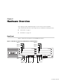
Chapter 1
Hardware Overview
This chapter provides detailed descriptions of the Secure Services Gateway
(SSG) 520 and SSG 550 device and components. It includes the following sections:
“Front Panel” on page 9
“Back Panel” on page 14
Front Panel
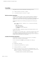
Figure 1 shows the front panel of an SSG 500-series device.
Figure 1: SSG 500-series Front Panel (SSG 550 Shown, SSG 520 Similar)
PIM Slot 1
PIM Slot 4
PIM Slot 2
PIM Slot 5
PIM Slot 3
PIM Slot 6
SSG 550M
Device status
LEDs
Power
button
Reset config
button
USB ports
AUX port
Ethernet
ports
Console port
Front Panel
9
SSG 500-series Installation and Configuration Guide
The following sections describe the elements on the front panel of an
SSG 500-series device:
“Port Descriptions” on page 10
“Power Button” on page 11
“Reset Config Button” on page 11
“Device Status LEDs” on page 11
“Ethernet Port LEDs” on page 12
“Physical Interface Module Slots” on page 13
“USB Ports” on page 13
Port Descriptions
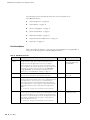
Table 1 describes the function, connector type, and speed/protocol (if applicable) of
the ports on the front panel of the SSG 500-series device.
Table 1: SSG 500-series Ports
Item
Description
Ethernet 0/0 to Enables ethernet connections to workstations or a LAN connection
0/3 Ports
through a switch or hub. These connections also allow you to
manage the device through a Telnet session or the WebUI.
Connector Speed/Protocol
RJ-45
10/100 Mbps Ethernet
Autosensing duplex and
auto MDI/MDIX
When configuring one of the ports, reference the interface name
that corresponds to the location of the port. From left to right on the
front panel, the interface names for the ports are ethernet0/0
through ethernet0/3. For the default zone bindings for each
Ethernet port, see “Default Device Settings” on page 33.
USB Port
Enables a 1.1 USB connection with the device. See “USB Ports” on
page 13 for more information about using the USB ports.
-
12M (full speed) or 1.5M
(low speed)
Console Port
The console port is an RJ-45 serial data terminal equipment (DTE)
port that can be used for either local or remote administration. For
local administration, connect the port to a terminal with an
RJ-45-to-DB-9 (female-to-male) straight-through serial cable. For
remote administration, connect the port to a workstation with an
RJ-45-to-DB-9 (female-to-male) serial cable with a null modem
adapter.
RJ-45
9600 bps/RS-232C serial
See “Connectors” on page 60 for the RJ-45 connector pinouts.
AUX Port
The auxiliary (AUX) port is an RJ-45 serial port wired as a DTE that RJ-45
you can connect to a modem to allow remote administration. We do
not recommend using this port for regular remote administration.
The AUX port is typically assigned to be the backup serial interface.
The baud rate is adjustable from 9600 bps to 115200 bps and
requires hardware flow control.
See “Connectors” on page 60 for the RJ-45 connector pinouts.
10
Front Panel
9600 bps — 115
Kbps/RS-232C serial
Hardware Overview
Power Button
The power button is located on the left side of the front panel. You use the power
button to power the device on and off. When you power on the device, ScreenOS
starts as the power supply completes its startup sequence. See “Powering the
Device On and Off” on page 26 for more information.
Reset Config Button
The Reset Config button restarts the device. You press this button by inserting a
thin, firm wire (such as a straightened paper clip) into the pinhole on the front
panel. You can also restart the device using the CLI and WebUI interfaces. See
“Restarting the Device” on page 41 for more information.
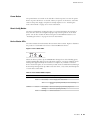
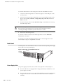
Device Status LEDs
The Device LEDs show information about current device status. Figure 2 illustrates
the position of each LED on the front of the SSG 500-series device.
Figure 2: Device Status LEDs
When the device powers up, the POWER LED changes from off to blinking green,
and the STATUS LED changes in the following sequence: red, green, blinking green.
Startup takes approximately two minutes to complete. If you want to turn the
device off and on again, we recommend you wait a few seconds between shutting it
down and powering it back up. Table 2 lists the name, color, status, and description
of each device status LED.
Table 2: Device Status LED Descriptions
Name
Color
Status
Description
POWER
Green
On steadily
Device is receiving power
Red
On steadily
Power Supply Unit (PSU) failure
Off
Device is operating normally or is not receiving
power
On steadily
Device is starting or performing diagnostics
Blinking
Device is operating normally
Blinking
Error is detected
STATUS
Green
Red
Front Panel
11
SSG 500-series Installation and Configuration Guide
Table 2: Device Status LED Descriptions (Continued)
Name
Color
Status
Description
ALARM
Red
On steadily
Critical alarm:
Failure of hardware component or software
module
Firewall attacks detected
Amber
On steadily
Major alarm:
Low memory (less than 10% remaining)
High CPU utilization (more than 90% in use)
Session full
Maximum number of VPN tunnels reached
HA status changed or redundant group member
not found
HA
Off
No alarms
Green
On steadily
Unit is the primary (master) device
Amber
On steadily
Unit is the secondary (backup) device
Off
High availability not enabled
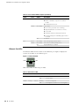
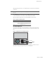
Ethernet Port LEDs
The Ethernet LEDs show the status of each Ethernet port. Figure 3 displays the
location of the LEDs on each Ethernet port.
Figure 3: Activity Link LEDs
TX/RX
LINK
Table 3 describes the Ethernet port LEDs.
Table 3: Ethernet Port LEDs
Name
Function
Color
State
Description
LINK
Link
Green
On steadily
Port is online
Off
Port is off line
Blinking
Port is receiving data
Off
Port might be on, but it is not receiving data
TX/RX
12
Front Panel
Activity
Green
Hardware Overview
Physical Interface Module Slots
Physical interface modules (PIMs) let you add Ethernet and WAN interfaces to your
SSG 500-series device. To install and remove PIMs, see “Replacing a PIM” on
page 46. For more information about installing and configuring PIMs, see the PIM
and Mini-PIM Installation and Configuration Guide.
CAUTION: PIMs are not hot-swappable. Always switch off the device before
inserting or removing PIMs.
Table 4 shows the PIM types you can install in the slots of an SSG 520 device. The E
located on some of the slots identifies where you can install enhanced PIMs
(ePIMs).
Table 4: PIM Slots, SSG 520
Slot
PIM Types
Slot PIM Types
1
WAN PIM or uPIM only
4
WAN PIM or uPIM only
2
WAN PIM or uPIM only
5
WAN PIM or uPIM only
3
WAN PIM, uPIM or ePIM
6
WAN PIM, uPIM or ePIM
Table 5 shows the PIM types you can install in the slots of an SSG 550 device. The E
located on some of the slots identifies where you can install enhanced PIMs
(ePIMs).
Table 5: PIM Slots, SSG 550
NOTE:
Slot
PIM Types
Slot PIM Types
1
WAN PIM or uPIM only
4
WAN PIM or uPIM only
2
WAN PIM, uPIM or ePIM
5
WAN PIM, uPIM or ePIM
3
WAN PIM, uPIM or ePIM
6
WAN PIM, uPIM or ePIM
When you install PIMs with Small Form-factor Pluggable (SFP) interfaces, Juniper
strongly recommends the use of Juniper SFP transceivers. Juniper cannot
guarantee correct operation if non-Juniper transceivers are used. The transceiver
type can be different in each port, as long as a supported part number is used.
USB Ports
The USB ports on the front panel of an SSG 500-series device accept a universal
serial bus (USB) storage device.
The USB ports let you transfer data such as device configurations, image keys, and
ScreenOS software between a USB storage device and the internal flash storage of
the security device. The USB ports support USB 1.1 and USB 2.0 specifications.
You can also log messages to a USB storage device. For more information about
logging, refer to the Administration volume of the Concepts and Examples ScreenOS
Reference Guide.
Front Panel
13
SSG 500-series Installation and Configuration Guide
To transfer data between a USB storage device and an SSG 500-series device:
1. Connect the USB storage device to either the upper or lower USB port on the
security device.
2. Save the files from the USB storage device to the internal flash storage on the
device with the save {software | config | image-key} from usb filename to
flash command.
3. Stop the USB port with the exec usb-device stop command before removing
the USB storage device.
CAUTION: Always execute the exec usb-device stop command before
disconnecting a USB storage device. Disconnecting a USB device without
executing the stop command may cause the device to restart.
4. Remove the USB storage device.
If you want to delete a file from the USB storage device, use the delete file
usb:/filename command.
If you want to view the saved file information on the USB storage device and
internal flash storage, use the get file command.
Back Panel
The back panel of an SSG 500-series device contains the fan tray and power supply
unit(s) and a two-hole grounding lug.
Figure 4: Back Panel of an SSG 500-series Device
Grounding
lugs
Power Supply Units
Power Supply Units
The power supply units (PSUs) are located at the right side of the back panel:
14
Back Panel
The SSG 520 device is equipped with a single permanently installed AC or DC
power supply unit (PSU).
The SSG 550 device has slots for two field-installable PSUs and is supplied with
a single AC or DC PSU. You can add a second AC or DC PSU for increased
reliability.
Hardware Overview
For PSU servicing instructions, see “Replacing Power Components (SSG 550 Only)”
on page 48.
NOTE:
Do not mix SSG 550 PSU types. The only supported combinations are AC+AC and
DC+DC.
The POWER LED on the front panel of an SSG 500-series device glows either green
or red. Green indicates correct function and red indicates PSU failure.
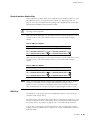
Table 6 describes the LED states on the field-installable AC and DC PSUs.
Table 6: Input Power LED Descriptions
Status
Color
Description
On steadily
Green
Input power is on and device is on
Amber
Input power is on and device is off
Off
Input power is off
AC Power Supply Unit
The fixed AC PSU faceplate for an SSG 520 device contains a power switch and a
male power-cord receptacle. The fixed AC PSU does not have a power LED on the
PSU.
Figure 5: SSG 520 Device Fixed AC PSU Faceplate
I
O
Power switch
Power cord
receptacle
The field-replaceable AC PSU faceplate for an SSG 550 device contains an ejector
tab handle, an input power light, and a power cord receptacle.
Back Panel
15
SSG 500-series Installation and Configuration Guide
Figure 6: SSG 550 Device Replaceable AC PSU Faceplate
Ejector tab
Input
power light
Power cord
receptacle
Handle
DC Power Supply Unit
The fixed DC PSU faceplate for an SSG 520 device contains an ejector tab, an input
power light, and two DC power terminal blocks that connect to power cables.
Figure 7: SSG 520 Device Fixed DC PSU Faceplate
Ejector tab
Input
power light
DC power
terminal
blocks
-48V
RTN
The field-replaceable DC PSU faceplate contains an ejector tab, a handle, an input
power light, and two DC power terminal blocks that connect to power cables.
Figure 8: SSG 550 Device Replaceable DC PSU Faceplate
Ejector tab
Input
power light
DC power
terminal
blocks
-48V
RTN
Handle
Grounding Lug
A two-hole grounding lug is provided on the left rear of the chassis to connect the
device to earth ground (see Figure 4 on page 14).
16
Back Panel
Hardware Overview
To ground the device before connecting power, connect a grounding cable to earth
ground and then attach the cable to the lug on the rear of the chassis. For more
information, see “Chassis Grounding” on page 22.
Back Panel
17
SSG 500-series Installation and Configuration Guide
18
Back Panel
Chapter 2
Installing and Connecting the Device
This chapter describes how to install an SSG 500-series device in a standard 19-inch
equipment rack and how to connect cables and power to the device. This chapter
includes the following sections:
NOTE:
“Before You Begin” on page 20
“Installing Equipment” on page 20
“Organizing Interface Cables” on page 22
“Chassis Grounding” on page 22
“Connecting Power” on page 22
“Powering the Device On and Off” on page 26
“Connecting the Device to a Network” on page 26
For safety warnings and instructions, refer to the Juniper Networks Security
Products Safety Guide. When working on any equipment, be aware of the hazards
involved with electrical circuitry, and follow standard practices for preventing
accidents.
19
SSG 500-series Installation and Configuration Guide
Before You Begin
The location of the chassis, the layout of the equipment rack, and the security of
your wiring room are crucial for proper device operation.
CAUTION: To prevent abuse and intrusion by unauthorized personnel, install the
device in a secure environment.
Observing the following precautions can prevent shutdowns, equipment failures,
and injuries:
Before installation, always check that the power supply is disconnected from
any power source.
Ensure that the room in which you operate the device has adequate air
circulation and that the room temperature does not exceed 104° F (40° C).
Allow three feet (one meter) of clear space to the front and back of the device.
Do not place the device in an equipment-rack frame that blocks an intake or
exhaust port. Ensure that enclosed racks have fans and louvered sides.
This device exceeds 18 pounds (8.2 kilograms). Take precautions when lifting
and stabilizing the device.
Correct these hazardous conditions before any installation: moist or wet floors,
leaks, ungrounded or frayed power cables, or missing safety grounds.
Installing Equipment
You can rack-mount the SSG 550-series device into a standard 19-inch equipment
rack. The device is shipped with mounting brackets. The equipment is suitable for
installation in locations where the National Electrical Code (NEC) applies, as well as
in Network Telecommunication Facilities.
You can center- or front-mount an SSG 500-series device in a rack. In general, a
center-mount rack is preferable to a front-mount rack because the more even
distribution of weight in the center-mount rack provides greater stability.
NOTE:
If you are installing multiple devices in one rack, install the lowest one first and
proceed upward in the rack.
CAUTION: The device weighs between 23 lb. (10.4 kg) and 31 lb. (14.1 kg).
Installing it into the rack requires at least one person to lift the device and a
second person to secure the mounting screws.
To mount the device, you must have number-2 phillips screwdriver (not provided)
and four screws that are compatible with the equipment rack (not provided).
20
Before You Begin
Installing and Connecting the Device
There are two ways to rack-mount an SSG 500-series device:
Center-mount—attach the left and right mounting brackets to the middle of
each side of the chassis.
Front-mount—attach the left and right mounting brackets to the front of each
side of the chassis.
To install an SSG 500-series device into a rack:
1. Have one person grasp the sides of the device, lift the device, and position it in
the rack.
2. Align the bottom hole in each mounting bracket with a hole in each rack rail,
making sure the chassis is level.
3. Have a second person install a mounting screw into each of the two aligned
holes. Use a number-2 phillips screwdriver to tighten the screws.
4. Install the remaining screws in each mounting bracket.
5. Verify that the mounting screws on one side of the rack are aligned with the
mounting screws on the opposite side and that the device is level.
Figure 9: Rack-Mount Installation
Center-mounting rack
Device rack-mounting brackets
When correctly installed, the device sits level in the equipment rack.
Installing Equipment
21
SSG 500-series Installation and Configuration Guide
Organizing Interface Cables
Arrange network cables as follows to prevent them from dislodging or developing
stress points:
Secure cables so that they are not supporting their own weight as they hang to
the floor.
Place excess cable out of the way in neatly coiled loops.
Use fasteners to maintain the shape of cable loops.
Chassis Grounding
To meet safety and electromagnetic interference (EMI) requirements, and to ensure
proper operation, the device must be adequately grounded before power is
connected. A two-hole grounding lug is provided on the rear of the chassis to
connect the device to earth ground (see Figure 4 on page 14).
CAUTION: Before device installation begins, a licensed electrician must attach a
cable lug to the grounding cable that you supply. A cable with an incorrectly
attached lug can damage the device (for example, by causing a short circuit).
The grounding cable must be American Wire Gauge (AWG) number-14 single-strand
wire cable and must be able to handle up to 6 ampere (A).
To ground the device before connecting power, you connect the grounding cable to
earth ground and then attach the cable to the lug on the rear of the chassis.
Connecting Power
This section describes how to connect AC and DC power to a device.
AC Power
The AC power cord shipped with the device connects the device to earth ground
when plugged into an AC grounding-type power outlet. The device must be
connected to earth ground during normal operation.
To connect AC power to the device:
1. Locate the power cord or cords shipped with the device, which has a plug
appropriate for your geographical location.
2. Attach an electrostatic discharge (ESD) grounding strap to your bare wrist, and
connect the strip to the ESD point on the chassis.
22
Organizing Interface Cables
Installing and Connecting the Device
3. Use a grounding cable to connect the device to earth ground, and do the
following:
a.
Verify that a licensed electrician has attached an appropriate
grounding-cable lug to the grounding cable.
b.
Connect one end of the grounding cable to a proper earth ground, such as
the rack in which the device is installed.
c.
Connect the other end of the grounding cable to the two-hole grounding lug
at the rear of an SSG 500-series device.
Figure 10: AC Grounding
Washer
Grounding lugs
4. For each power supply unit (PSU), do the following:
a.
Insert the appliance-coupler end of a power cord into the appliance inlet on
the power-supply faceplate.
b.
Insert the plug into an AC power-source receptacle.
5. Verify that the power cord does not block access to device components or
drape where people can trip on it.
DC Power
Each DC PSU has a single DC input (–48 VDC and return) that requires a dedicated
25 A (–48 VDC) circuit breaker.
CAUTION: If your device includes an optional redundant DC PSU, connect each of
the two power supplies to different input-power sources. Failure to do so makes
the device susceptible to total power failure if one of the power supplies fails.
Most sites distribute DC power through a main conduit that leads to frame-mounted
DC power distribution panels, one of which might be located at the top of the rack
that houses the router. A pair of cables (one input and one return) connects each set
of terminal studs to the power distribution panel.
Connecting Power
23
SSG 500-series Installation and Configuration Guide
CAUTION: There is no standard color coding for DC power cables. The color coding
used by the external DC power source at your site determines the color coding for
the leads on the power cables that attach to the terminal studs on each power
supply. You must ensure that power connections maintain the proper polarity. The
power source cables might be labeled (+) and (–) to indicate their polarity.
The device must be connected to earth ground during normal operation. The
protective grounding terminal on the rear of the chassis is provided to connect the
device to ground.
WARNING: Power-plant ground and chassis ground must be connected to the same
building ground.
The DC return terminal must be connected to the central office (CO) ground. This
common DC return connection (DC-C) and the –48 VDC connection must both be
14 AWG single-strand wire cable (minimum). Each lug attached to the power cables
must be U-type.
To connect DC power to the device:
1. Attach an electrostatic discharge (ESD) grounding strap to your bare wrist, and
connect the strip to the ESD point on the chassis.
2. Use a grounding cable to connect the device to earth ground, and do the
following:
a.
Verify that a licensed electrician has attached an appropriate
grounding-cable lug to the grounding cable.
b.
Connect one end of the grounding cable to a proper earth ground, such as
the rack in which the device is installed.
c.
Connect the other end of the grounding cable to the two-hole grounding lug
at the rear of the device (Figure 11).
3. For each power supply, do the following:
a.
Ensure that the voltage across the DC power source cable leads is 0 V and
that there is no chance that the cable leads might become active during
installation.
b.
Verify that a licensed electrician has attached the appropriate power-cable
lugs to the negative and positive DC source power cables.
c.
Within the terminal block, loosen the two center screws next to the labels
–48 VDC and RTN.
Each screw contains a washer used to secure a DC source power-cable lug
to the terminal block.
24
Connecting Power
Installing and Connecting the Device
Figure 11: Connecting DC Power-Cable Lugs
DC terminal block
Lug
-48V
RTN
Washer
Grounding lugs
Screw with
captive
washer
d. Secure the positive (+) DC source power-cable lug to the RTN terminal.
e.
Secure the negative (–) DC source power-cable lug to the –48 VDC terminal.
f.
Dress the power cables appropriately.
CAUTION: Ensure that the DC cables do not touch the two screws on the chassis
that are adjacent to the terminal block. Contact between the DC cables and the
chassis screws will cause a circuit failure.
4. Verify that the power cord does not block access to device components or
drape where people can trip on them.
Connecting Power
25
SSG 500-series Installation and Configuration Guide
Powering the Device On and Off
To power on the device, press the power button. ScreenOS starts as the power
supply completes its startup sequence. The POWER LED illuminates during startup
and remains on steadily when the device is operating normally.
NOTE:
The PSU in the rear panel of the device may include a power switch. If such a
switch is included, make sure the switch is in the ON position.
To power off a device, press the power button and hold it for more than 5 seconds.
To remove power completely from the device, unplug the power cord. The power
button on the device is a standby power switch.
CAUTION: If the device is connected to an AC power-source receptacle when you
press the power button to power off, the device remains in standby mode, and a
small amount (5 V and 3.3 V) of standby voltage is still available in the chassis.
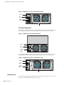
Connecting the Device to a Network
This section provides basic information on how to physically connect the
SSG 500-series device.
To connect the necessary cables as shown in Figure 12:
1. Connect an RJ-45 cable from the port labeled 0/0 (ethernet0/0 interface) to the
internal switch. The ethernet0/0 interface is prebound to the Trust security
zone.
2. Connect an RJ-45 cable from the port labeled 0/1 (ethernet0/1 interface) to the
DMZ switch. The ethernet0/1 interface is prebound to the DMZ security zone.
3. Connect an RJ-45 cable from the port labeled 0/2 (ethernet0/2 interface) to the
external switch or router. The ethernet0/2 interface is prebound to the Untrust
security zone. The device auto-senses the correct speed, duplex, and MDI/MDIX
settings.
4. Connect an RJ-45 cable from the Console port using the instructions provided
in “Using a Console Connection” on page 30 for management access.
26
Powering the Device On and Off
Installing and Connecting the Device
Figure 12: Basic Cabling Example
T1
T1
Untrust Network
PORT 0
PORT 1
PORT 0
STATUS
STATUS
T1
PORT 1
PORT 0
STATUS
AL
WER
AR
M
STATUS
0
TX/RX
SLOT NUMBER
US
AT
ST
HA
POWER
RESET
CONFIG
TX/RX
0/0 LINK
TX/RX
0/1 LINK TX/RX 0/2 LINK
10/100/1000
TX/RX
Console
STATUS
10/100/1000
LINK
0
PO
PORT 1
STATUS
GB SFP
0/3 LINK
CONSOLE
AUX
Internal Switch
Trusted LAN
PORT 1
STATUS
T1
STATUS
PORT 0
USB
1
2
3
4
5
6
SSG 550M
DMZ Switch
DMZ LAN
WARNING: Make sure that you do not inadvertently connect the Console, AUX, or
Ethernet ports on the device to the telephone outlet.
Connecting the Device to a Network
27
SSG 500-series Installation and Configuration Guide
28
Connecting the Device to a Network
Chapter 3
Configuring the Device
ScreenOS software is preinstalled on SSG 500-series devices. When the device is
started, it is ready to be configured. While the device has a default factory
configuration that lets you initially connect to the device, you must perform further
configuration for your specific network requirements.
This chapter includes the following sections:
NOTE:
“Accessing the Device” on page 30
“Default Device Settings” on page 33
“Basic Device Configuration” on page 33
“High Availability Configuration” on page 37
“PIM Configuration” on page 40
“Basic Firewall Protections” on page 40
“Verifying External Connectivity” on page 40
“Restarting the Device” on page 41
“Resetting the Device to Factory Defaults” on page 42
After you configure an SSG 500-series device and verify connectivity through the
remote network, you must register your product at
http://www.juniper.net/customers/support/ so that certain ScreenOS services, such
as Deep Inspection (DI) Signature Service and Antivirus (AV), can be activated on
the device. After registering your product, use the WebUI to obtain the
subscription for the service. For more information about registering your product
and obtaining subscriptions for specific services, refer to the Fundamentals volume
of the Concepts & Examples ScreenOS Reference Guide.
29
SSG 500-series Installation and Configuration Guide
Accessing the Device
You can configure and manage an SSG 500-series device in several ways:
Console—The Console port on the device lets you access the device through a
serial cable connected to your workstation or terminal. To configure the device,
you enter ScreenOS command line interface (CLI) commands on your terminal
or in a terminal-emulation program on your workstation. For more information,
see “Using a Console Connection” on page 30.
Remote Console—You can remotely access the console interface on a security
device by dialing into it. You can either dial into the v.92 modem port or into a
modem connected to the AUX port. For more information, refer to the
Administration volume of the Concepts & Examples ScreenOS Reference Guide.
WebUI—The ScreenOS Web user interface (WebUI) is a graphical interface
available through a browser. To initially use the WebUI, the workstation on
which you run the browser must be on the same subnetwork as the device. You
can also access the WebUI through a secure server using Secure Sockets Layer
(SSL) with secure HTTP (HTTPS).
Telnet/SSH—Telnet and SSH are applications that allow you to access devices
through an IP network. To configure the device, you enter ScreenOS CLI
commands in a Telnet session from your workstation. For more information,
refer to the Administration volume of the Concepts & Examples ScreenOS
Reference Guide.
Network and Security Manager—Network and Security Manager is a Juniper
Networks enterprise-level management application that enables you to control
and manage Juniper Networks security devices. For instructions on how to
manage your device with Network and Security Manager, refer to the Network
and Security Manager Administrator’s Guide.
Using a Console Connection
NOTE:
Use a straight-through RJ-45 CAT5 cable with a male RJ-45 connector to plug into
the Console port on the device.
To establish a console connection with the device:
1. Plug the female end of the supplied DB-9 adapter into the serial port of your
workstation. (Be sure that the DB-9 is inserted properly and secured.)
2. Plug one end of the RJ-45 CAT5 cable into the DB-9 adapter.
30
Accessing the Device
Configuring the Device
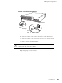
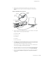
3. Plug the other end of the RJ-45 CAT5 cable into the Console port on the
SSG 500-series device. Figure 13 shows the arrangement of the cable and
adapter.
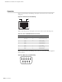
Figure 13: Establishing a Console Connection
Serial port on
workstation
DB-9 adapter
CAT5 RJ-45
cable
Console port on
SSG 500-series
device
BER
NUM
SLOT
0
1
PORT
0
PORT
W
PO
ER
US
AT
ST
HA
POWER
1
E
CONSOL
RESET
CONFIG
10/100
AUX
1
2
3
E
E
4
5
6
E
E
USB
/1000
g003510
M
AR
AL
STATUS
STATUS
4. Launch a serial terminal-emulation program on your workstation. The required
settings to launch a console session are as follows:
Baud rate: 9600
Parity: None
Data bits: 8
Stop bit: 1
Flow Control: None
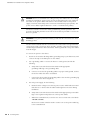
5. If you have not yet changed the default login for the login name and password,
enter netscreen at both the login and password prompts. (Use lowercase letters
only. The login and password fields are both case-sensitive)
For information on how to configure the device with the CLI commands, refer
to the Concepts & Examples ScreenOS Reference Guide.
6. (Optional) By default, the console times out and terminates automatically after
10 minutes of idle time. To remove the timeout, enter set console timeout 0.
7. Once the command prompt is displayed, the device is ready to be configured,
See “Basic Device Configuration” on page 33 to complete the initial device
configuration.
Accessing the Device
31
SSG 500-series Installation and Configuration Guide
Using the WebUI
To use the WebUI, the workstation from which you are managing the device must
initially be on the same subnetwork as the device. To access the device with the
WebUI:
1. Connect your workstation to the port labeled 0/0 (ethernet0/0 interface), which
is prebound to the Trust security zone.
2. Ensure that your workstation is configured with a static IP address in the
192.168.1.0/24 subnet.
3. Launch your browser, enter the IP address for the ethernet0/0 interface (the
default IP address is 192.168.1.1), then press Enter.
The WebUI application displays the login prompt.
4. If you have not yet changed the default login for the admin name and
password, enter netscreen at both the admin name and password prompts.
(Use lowercase letters only. The admin name and password fields are both
case-sensitive.)
5. Once the WebUI homepage opens, the device is ready to be configured. See
“Basic Device Configuration” on page 33 to complete the initial device
configuration.
Using Telnet
To use a Telnet connection, the workstation must be in the same subnetwork as the
security device. To access the device with a Telnet connection:
1. Connect your workstation to the port labeled 0/0 (ethernet0/0 interface), which
is prebound to the Trust security zone.
2. Ensure that your workstation is configured with a static IP address in the
192.168.1.0/24 subnet.
3. Start a Telnet client application to the IP address for the ethernet0/0 interface
(the default IP address is 192.168.1.1). For example, enter telnet 192.168.1.1.
The Telnet application displays the login prompt.
4. If you have not yet changed the default login for the login name and password,
enter netscreen at both the login and password prompts. (Use lowercase letters
only. The login and password fields are both case-sensitive)
5. (Optional) By default, the console times out and terminates automatically after
10 minutes of idle time. To prevent the console from timing out and
terminating automatically, enter set console timeout 0.
32
Accessing the Device
Configuring the Device
Default Device Settings
Table 7 describes the default interface-to-zone bindings on an SSG 500-series
device.
Table 7: Default Interface-to-Zone Bindings
Port Label
Interface
Zone
0/0
ethernet0/0 (default IP address is 192.168.1.1/24)
Trust
0/1
ethernet0/1
DMZ
0/2
ethernet0/2
Untrust
0/3
ethernet0/3
HA
Note that the ethernet0/0 interface has the default IP address 192.168.1.1/24 and is
configured for management services. If you connect the ethernet0/0 port on the
device to a workstation, you can configure the device from a workstation in the
192.168.1.1/24 subnetwork using a management service such as Telnet. You can
change the default IP address on the ethernet0/0 interface to match the addresses
on your LAN. There are no other default IP addresses configured on other ports on
the device; you must assign IP addresses to other interfaces.
Basic Device Configuration
The following sections describe the basic configuration tasks required to place an
SSG 500-series device in operation:
“Admin Name and Password” on page 34
“Administrative Access” on page 34
“Interface IP Address” on page 34
“Management Services” on page 35
“Hostname and Domain Name” on page 35
“Domain Name System Server” on page 36
“Date and Time” on page 36
“Default Route” on page 36
The examples in this section demonstrate how to establish initial network
connectivity. For advanced configuration information, refer to the Concepts &
Examples ScreenOS Reference Guide.
Default Device Settings
33
SSG 500-series Installation and Configuration Guide
Admin Name and Password
The administrative user has complete privileges to configure a device. We
recommend that you change the default admin name (netscreen) and password
(netscreen) immediately.
To change the admin name and password:
WebUI
Configuration > Admin > Administrators > Edit (for the NetScreen
Administrator Name): Enter the following, then click OK:
Administrator Name:
Old Password: netscreen
New Password:
Confirm New Password:
CLI
set admin name name
set admin password pswd_str
save
Administrative Access
By default, anyone on your network who knows the login and password can
manage your device.
To configure a device to be managed only from a specific host on your network:
WebUI
Configuration > Admin > Permitted IPs: Enter the following, then click Add:
IP Address/Netmask: ip_addr/mask
CLI
set admin manager-ip ip_addr/mask
save
Interface IP Address
The ethernet0/0 interface has the default IP address 192.168.1.1/24 and is
preconfigured for management services. You can configure the device using a
management service such as Telnet by connecting a workstation to the ethernet0/0
interface. The workstation must have an IP address in the 192.168.1.1/24 subnet.
To change the default interface IP address on the device:
WebUI
Network > Interfaces > Edit (for ethernet0/0): Enter the following, then click
OK:
IP Address/Netmask: ip_addr/mask
34
Basic Device Configuration
Configuring the Device
CLI
set interface ethernet0/0 ip ip_addr/mask
save
Management Services
ScreenOS provides services for configuring and managing a device, such as SNMP,
SSL, and SSH, which you can enable on a per-interface basis. You cannot configure
WAN interfaces for management services.
To configure the management services for the ethernet0/0 interface:
WebUI
Network > Interfaces > Edit (for ethernet0/0): Under Management Services,
select or clear the management services you want to use on the interface, then
click Apply.
CLI
set interface eth0/0 manage web
unset interface eth0/0 manage snmp
save
Hostname and Domain Name
The domain name defines the network or subnetwork that the device belongs to,
while the hostname refers to a specific device. The hostname and domain name
together uniquely identify a device in the network. To configure the hostname and
domain name on the device:
WebUI
Network > DNS > Host: Enter the following, then click Apply:
Host Name: hostname
Domain Name: domain-name
CLI
set hostname hostname
set domain domain-name
save
Basic Device Configuration
35
SSG 500-series Installation and Configuration Guide
Domain Name System Server
The Domain Name System (DNS) server on the network maintains a database for
resolving hostnames and IP addresses. Devices access the configured DNS servers
to resolve hostnames. In ScreenOS, you configure the IP addresses for the primary
and secondary DNS servers and the time of the day at which the device performs a
DNS refresh.
To configure the DNS server IP address:
WebUI
Network > DNS > Host: Enter the following, then click Apply:
Primary DNS Server: ip_addr
Secondary DNS Server: ip_addr
DNS Refresh: (select)
Every Day at: time
CLI
set dns host name ip_addr
set dns host name ip_addr
set dns host schedule time
save
Date and Time
The time settings on a device affect events such as the setup of virtual private
network (VPN) tunnels. The easiest way to set the date and time on the device is to
use the WebUI to synchronize the device clock with the clock on your workstation.
To configure the date and time on the device:
WebUI
1. Configuration > Date/Time: Click the Sync Clock with Client button.
A pop-up message prompts you to specify if you have enabled the daylight
saving time option on your workstation clock.
2. Click Yes to synchronize the device clock and adjust it according to daylight
saving time, or click No to synchronize the device clock without adjusting
for daylight saving time.
You can also use the CLI set clock command in a Telnet or console session to
manually enter the date and time for the device.
Default Route
The default route is a static route used to direct packets addressed to networks that
are not explicitly listed in the routing table. If a packet arrives at the device with an
address for which the device does not have routing information, the device sends
the packet to the destination specified by the default route. To configure the default
route on the device:
36
Basic Device Configuration
Configuring the Device
WebUI
Network > Routing > Destination > New (trust-vr): Enter the following, then
click OK:
Network Address/Netmask: 0.0.0.0/0.0.0.0
Gateway: (select)
Interface: ethernet0/2 (select)
Gateway IP Address: ip_addr
CLI
set route 0.0.0.0/0 interface ethernet0/2 gateway ip_addr
save
High Availability Configuration
An HA port lets you cable two devices together and configure them to work as a
redundant group. A redundant group consists of one primary device and one backup
device. If the primary device fails, the backup device takes over as the new primary,
thus avoiding interruption of services.
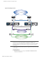
This section describes how to connect your device for high availability.
NOTE:
Do not mix port interface types. HA configuration is not supported on WAN
interfaces. You must have the same hardware configuration for both devices for
HA to work correctly. For more information about HA configuration, refer to the
Concepts & Examples ScreenOS Reference Guide.
High Availability Configuration 37
SSG 500-series Installation and Configuration Guide
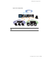
Figure 14: HA Cabling Connections
Untrust Zone
R1
R2
Switch F
Switch C
T1
PORT 1
PORT 0
T1
STATUS
10/100/1000
10/100/1000
LINK
PO
M
AR
1
2
POWER
RESET
CONFIG
TX/RX
0/0 LINK
TX/RX
0/1 LINK TX/RX 0/2 LINK
10/100/1000
TX/RX
0/3 LINK
CONSOLE
AUX
USB
1
2
3
4
5
6
SSG 550
SSG 550
WER
STATUS
10/100/1000
10/100/1000
LINK
PO
M
AR
1
2
SLOT NUMBER
POWER
AL
RESET
CONFIG
TX/RX
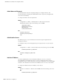
0/0 LINK
TX/RX
0/1 LINK TX/RX 0/2 LINK
10/100/1000
TX/RX
0/3 LINK
CONSOLE
AUX
Trust Zone
Switch B
USB
1
2
3
4
5
6
SSG 550M
SSG 550
HA port
Switch A
STATUS
00
TX/RX
3
US
AT
ST
HA
STATUS
PORT 1
TX/RX
STATUS
0
0
SLOT NUMBER
AL
PORT 0
0
GB
SFP
4x10/100
00
PORT 1
STATUS
LINK
PORT 1
STATUS
STATUS
TX/RX
3
US
AT
ST
HA
PORT 0
PORT 1
TX/RX
STATUS
0
0
WER
PORT 0
STATUS
GB SFP
PORT 0
0
PORT 1
STATUS
STATUS
T1
STATUS
LINK
PORT 1
STATUS
PORT 0
PORT 1
STATUS
T1
STATUS
PORT 0
T1
T1
T1
PORT 0
GB SFP
GB
SFP
4x10/100
T1
802.1 Q trunk
Switch D
Switch E
DMZ Zone
NOTE:
The provided cabling instructions reproduce the configuration shown in Figure 14;
however, this is not the only possible HA configuration. In addition, the
instructions assume that all physical ports and interfaces are still at their defaults.
If you have changed the port and interface settings, the instructions might not
work properly.
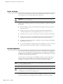
To cable SSG 550 and SSG 550 security devices together for HA and connect them
to the network:
Configuring HA Ports
1. Set the HA interface by executing the set interface ethernet0/3 zone ha
command on both devices.
38
High Availability Configuration
Configuring the Device
Primary Unit
2. Connect a crossover cable from ethernet0/0 to Switch A.
3. Connect a crossover cable from ethernet0/1 to Switch B.
4. Connect a crossover cable from ethernet0/2 to Switch C.
Backup Unit
5. Connect a crossover cable from ethernet0/0 to Switch D.
6. Connect a crossover cable from ethernet0/1 to Switch E.
7. Connect a crossover cable from ethernet0/2 to Switch F.
Switches
8. Cable together Switch A and Switch D.
9. Cable together Switch B and Switch E.
10. Cable together Switch C and Switch F.
11. Cable Switch C to R1.
12. Cable Switch F to R2.
NOTE:
The switch ports must be defined as 802.1Q trunk ports, and the external routers
must be able to use either Hot Standby Router Protocol (HSRP) or Virtual Router
Redundancy Protocol (VRRP). For the best configuration method, refer to the
documentation for your switch or router.
13. Press the power switch to the ON position for both devices.
High Availability Configuration 39
SSG 500-series Installation and Configuration Guide
PIM Configuration
To configure the interfaces on physical interface modules (PIMs), refer to the PIM
and Mini-PIM Installation and Configuration Guide.
Basic Firewall Protections
The devices are configured with a default policy that permits workstations in the
Trust zone of your network to access any resource in the Untrust security zone,
while outside computers are not allowed to access or start sessions with your
workstations. You can configure policies that direct the device to permit outside
computers to start specific kinds of sessions with your computers. For information
about creating or modifying policies, refer to the Concepts & Examples ScreenOS
Reference Guide.
SSG 500-series devices provide various detection methods and defense
mechanisms to combat probes and attacks aimed at compromising or harming a
network or network resource:
ScreenOS Screen options secure a zone by inspecting, and then allowing or
denying, all connection attempts that require crossing an interface to that zone.
For example, you can apply port-scan protection on the Untrust zone to stop a
source from a remote network from trying to identify services to target for
further attacks.
The device applies firewall policies, which can contain content filtering and
Intrusion Detection and Prevention (IDP) components, to the traffic that passes
the Screen filters from one zone to another. By default, no traffic is permitted to
pass through the device from one zone to another. To permit traffic to cross the
device from one zone to another, you must create a policy that overrides the
default behavior.
To set ScreenOS Screen options for a zone:
WebUI
Screening > Screen: Select the zone to which the options apply. Select the
Screen options that you want, then click Apply:
CLI
set zone zone screen option
save
For more information about configuring the network security options available in
ScreenOS, refer to the Attack Detection and Defense Mechanisms volume of the
Concepts & Examples ScreenOS Reference Guide.
Verifying External Connectivity
To verify that workstations in your network can access resources on the Internet,
start a browser from any workstation in the network and browse to
www.juniper.net/.
40
PIM Configuration
Configuring the Device
Restarting the Device
You may need to restart the device in order to implement new features, such as
when you change between route and transparent mode or when you add new
license keys.
The following sections describe two methods of restarting the device:
“Restarting the Device with the CLI Reset Command” on page 41
“Restarting the Device with the WebUI” on page 41
Restarting the Device with the CLI Reset Command
To restart the device with the CLI reset command:
1. Establish a console session with the device as described in “Using a Console
Connection” on page 22 or “Using Telnet” on page 24.
At a Windows workstation, the easiset way of opening a console connection is
to choose Start > Run and enter telnet ip_address.
The device prompts you for your login and password.
2. If you have not yet changed the default username and password, enter
netscreen at both the login and password prompts. (Use lowercase letters only.
The login and password fields are both case-sensitive.)
3. At the console prompt, enter:
reset
The device prompts you to confirm the reset:
System reset, are you sure? y/[n]
4. Enter Y.
The device restarts.
Restarting the Device with the WebUI
To restart the device with the WebUI:
1. Launch your browser and enter the IP address for the management interface
(the default IP address is 192.168.1.1), then press Enter.
The WebUI application displays the login prompt.
2. If you have not yet changed the default username and password, enter
netscreen at both the login and password prompts. (Use lowercase letters only.
The login and password fields are both case-sensitive.)
3. In the WebUI, choose:
Configuration > Update > ScreenOS/Keys
Restarting the Device 41
SSG 500-series Installation and Configuration Guide
4. Click Reset.
An alert box prompts you to confirm that you want to reset the device.
5. Click OK.
The device resets. Also, an alert box prompts you to leave your browser open
for a few minutes and then log back into the device.
Resetting the Device to Factory Defaults
If you lose the admin password, or you need to clear the configuration of your
device, you can reset the device to its factory default settings. Resetting the device
destroys any existing configurations and restores access to the device.
CAUTION: Resetting the device deletes all existing configuration settings and
disables all existing firewall and VPN services.
NOTE:
By default, the device recovery feature is enabled. You can disable it by entering
the CLI unset admin device-reset command. Also, if the security device is in FIPS
mode, the recovery feature is automatically disabled.
You can restore the device to its default settings using one of these methods:
Using the device serial number
Using the CLI unset all command
Using the Reset Config pinhole button
The following sections describe how to use these methods to reset the device to its
factory defaults.
Device Serial Number
To use the device serial number to reset the device to its factory defaults:
1. Start a Console session as described in “Using a Console Connection” on
page 30.
2. At the Login prompt, enter the device serial number.
3. At the Password prompt, enter the serial number again. The following message
appears:
!!! Lost Password Reset !!! You have initiated a command to reset the device to
factory defaults, clearing all current configuration and settings. Would you like to
continue? y/[n]
42
Resetting the Device to Factory Defaults
Configuring the Device
4. Press the y key. The following message appears:
!! Reconfirm Lost Password Reset !! If you continue, the entire configuration of the
device will be erased. In addition, a permanent counter will be incremented to
signify that this device has been reset. This is your last chance to cancel this
command. If you proceed, the device will return to factory default configuration,
which is: device IP: 192.168.1.1; username: netscreen, password: netscreen.
Would you like to continue? y/[n]
5. Press the y key to reset the device.
The system now resets and returns to the login prompt; the default login name and
password are both reset to netscreen.
unset all
To use the CLI unset all command, you will need to know the login name and
password. To reset the device to its factory defaults:
1. Start a Console session as described in “Using a Console Connection” on
page 30, then log in.
2. At the command prompt, enter unset all. The following message is displayed:
Erase all system config, are you sure y/[n] ?
3. Press y
4. Enter reset. Press n for the first question and y for the second question:
Configuration modified, save? [y]/n
System reset, are you sure? y/[n]
The system now resets and returns to the login prompt; the default login name and
password are both reset to netscreen.
Resetting the Device to Factory Defaults
43
SSG 500-series Installation and Configuration Guide
44
Resetting the Device to Factory Defaults
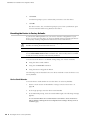
Chapter 4
Servicing the Device
This chapter describes service and maintenance procedures for SSG 500-series
devices. It includes the following sections:
NOTE:
“Required Tools and Parts” on page 45
“Replacing a PIM” on page 46
“Replacing Power Components (SSG 550 Only)” on page 48
“Upgrading Memory” on page 52
“Replacing the Air Filter” on page 54
For safety warnings and instructions, refer to the Juniper Networks Security
Products Safety Guide. The instructions in the guide warn you about situations that
could cause bodily injury. When working on any equipment, be aware of the
hazards involved with electrical circuitry, and follow standard practices for
preventing accidents.
Required Tools and Parts
To replace a component on an SSG 500-series device, you need the following tools
and parts:
Electrostatic bag or antistatic mat
Electrostatic discharge (ESD) grounding wrist strap
Flat-tip screwdriver, 1/8-inch
Number-2 phillips screwdriver
Required Tools and Parts
45
SSG 500-series Installation and Configuration Guide
Replacing a PIM
Both SSG 500-series devices have six slots in the front panel for Ethernet or WAN
physical interface modules (PIMs). PIMs are field installable and replaceable.
CAUTION: Power off the device before removing or installing PIMs. PIMs are not
hot-swappable.
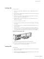
Removing a Blank Faceplate
To maintain proper airflow through the device, blank faceplates should remain over
slots that do not contain PIMs. Do not remove a blank faceplate unless you are
installing a PIM in the empty slot.
To remove a blank faceplate:
1. Attach an ESD grounding strap to your bare wrist, and connect the strap to the
ESD point on the device.
2. If the device is powered on, press and release the power button to power off the
device. Verify that the POWER LED is off.
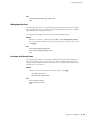
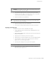
3. Loosen the screws on each side of the faceplate as shown in Figure 15:
On faceplates with handles, use a 1/8-inch flat-tip screwdriver to loosen but
do not remove the captive screws.
On faceplates without handles, use a number-1 phillips screwdriver to
remove the non-captive screws.
Figure 15: Identifying Blank Faceplate Types
Handles
Blank Faceplate
with Handles
Loosen captive screws
with 1/8-inch flat-tip
screwdriver
Remove screws with
number-1 Phillips
screwdriver
4. Remove the faceplate.
46
Replacing a PIM
Blank Faceplate
without Handles
Servicing the Device
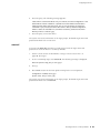
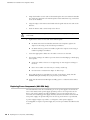
Removing a PIM
To remove a PIM:
1. Place an electrostatic bag or antistatic mat on a flat, stable surface to receive
the PIM.
2. Attach an ESD grounding strap to your bare wrist, and connect the strap to the
ESD point on the device.
3. If the device is powered on, press and release the power button to power off
the device. Verify that the POWER LED is off.
4. Label the cables connected to the PIM so that you can later reconnect each
cable to the correct PIM.
5. Disconnect the cables from the PIM.
6. If necessary, arrange the cables to prevent them from dislodging or developing
stress points.
7. Loosen the captive screws on each side of the PIM faceplate using a 1/8-inch
flat-tip screwdriver.
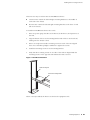
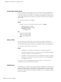
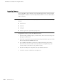
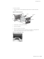
8. Grasp the handles on each side of the PIM faceplate, and slide the PIM out of
the device (see Figure 16). On some PIMs the handles are metal ears attached
to the PIM faceplate. Other PIMs have long screws that serve as the handles.
Figure 16: Removing/Installing a PIM
0
1
O
CONS
ER
M
AR
AL
US
AT
ST
HA
R
POWE
T
RESE
IG
CONF
/1000
10/100
SERIAL
W
PO
STATU
PORT
S
X
LE AU
ER
NUMB
SLOT
4
E
1
5
E
E
2
6
E
3
USB
1
PORT
S
STATU
0
9. Place the PIM in the electrostatic bag or on the antistatic mat.
10. If you are not reinstalling a PIM into the empty slot, install a blank PIM
faceplate over the slot to maintain proper airflow.
Installing a PIM
To install a PIM:
1. Attach an ESD grounding strap to your bare wrist, and connect the strap to the
ESD point on the device.
2. If the device is powered on, press and release the power button to power off the
device. Verify that the POWER LED is off.
Replacing a PIM
47
SSG 500-series Installation and Configuration Guide
3. Grasp the handles on each side of the PIM faceplate. On some PIMs the handles
are metal ears attached to the PIM faceplate. Other PIMs have long screws that
serve as the handles.
4. Align the edges of the PIM circuit board with the guide rails at each side of the
PIM slot.
5. Slide the PIM in until it seats firmly in the device.
CAUTION: Slide the PIM straight into the slot to avoid damaging the components
on the PIM.
6. Tighten the screws on each side of the PIM faceplate:
On PIMs with metal ear handles attached to the faceplate, tighten the
captive screws using a 1/8-inch flat-tip screwdriver.
On PIMs with long screws for handles, tighten the captive screws using a
number-2 phillips screwdriver.
7. Insert the appropriate cables into the cable connectors on the PIM.
8. If necessary, arrange the cables to prevent them from dislodging or developing
stress points:
Secure the cable so that it is not supporting its own weight as it hangs to
the floor.
Place excess cable out of the way in a neatly coiled loop.
Use fasteners to maintain the shape of cable loops.
9. Press and release the power button to power on the device. Verify that the
POWER LED lights steadily after you press the power button.
10. Verify that the PIM status LED lights steadily green to confirm that the PIM is
online.
Replacing Power Components (SSG 550 Only)
The SSG 550 device has two load-sharing AC or DC power supplies located at the
rear of the chassis. Each power supply provides power to all components in the
device. The power supplies are fully redundant. If one power supply fails or is
removed, the remaining power supply instantly assumes the entire electrical load.
One power supply can provide full power for as long as the device is operational.
A power supply weighs 2.4 pounds. (1.1 kilogram.). Each power supply is
hot-swappable. To replace a power-supply unit, use the procedures described in this
section.
48
Replacing Power Components (SSG 550 Only)
Servicing the Device
CAUTION: Do not leave a power supply slot empty while the device is operational.
The power supply or a blank power-supply faceplate must remain in the chassis
for proper airflow.
Removing a Power Supply Unit
To remove an AC power-supply unit (PSU) from a device:
1. Attach an ESD grounding strap to your bare wrist, and connect the strap to the
ESD point on the device.
2. Unplug the power cord from the power-source receptacle.
3. Unplug the power cord from the appliance inlet on the power-supply faceplate.
4. With your thumb, slide the metal ejector tab on the power-supply faceplate to
the right, and hold it in place to unlock the PSU.
Figure 17: Sliding AC/DC Power Supply Ejector Tab
Metal
ejector tab
5. Grasp the handle on the power-supply faceplate, and pull firmly to start
removing the power supply. Slide it halfway out of the chassis as shown in
Figure 17.
6. Place one hand underneath the power supply to support it, then slide it
completely out of the chassis.
NOTE:
If you are not reinstalling a power supply into the emptied slot, install a blank
power-supply faceplate over the slot.
To remove a DC PSU:
1. Attach an ESD grounding strap to your bare wrist, and connect the strap to the
ESD point on the device.
WARNING: Before removing a DC PSU, you must shut off current to the DC feed
wires that lead to the PSU.
Replacing Power Components (SSG 550 Only) 49
SSG 500-series Installation and Configuration Guide
2. Loosen the retaining screws on the terminal block.
3. Remove the feed wires.
CAUTION: Ensure that the DC cables do not touch the two screws on the chassis
that are adjacent to the terminal block. Contact between the DC cables and the
chassis screws will cause a circuit failure.
4. With your thumb, slide the ejector tab on the power-supply faceplate to the
right, and hold it in place to unlock the power supply.
5. Grasp the handle on the power-supply faceplate, and pull firmly to start
removing the power supply. Slide it halfway out of the chassis as shown in
Figure 17.
6. Place one hand underneath the power supply to support it, then slide it
completely out of the chassis.
NOTE:
If you are not reinstalling a power supply into the emptied slot, install a blank
power-supply faceplate over the slot.
Installing a Power Supply Unit
To install an AC PSU:
1. Attach an ESD grounding strap to your bare wrist, and connect the strap to the
ESD point on the chassis or to an outside ESD point if the device is
disconnected from earth ground.
2. Using both hands, slide the PSU into the chassis until you feel resistance.
3. Firmly push the power supply into the chassis until it comes to a stop. Make
sure that the PSU is flush with any other adjacent PSU.
4. Insert the appliance-coupler end of a power cord into the appliance inlet on the
power-supply faceplate.
5. Insert the power-cord plug into an AC power-source receptacle.
NOTE:
Each power supply must be connected to a dedicated AC power feed.
6. Verify that the power cord does not block access to device components or
drape where people might trip on it.
To install a DC PSU:
1. Attach an ESD grounding strap to your bare wrist, and connect the strap to the
ESD point on the chassis or to an outside ESD point if the SSG device is
disconnected from earth ground.
50
Replacing Power Components (SSG 550 Only)
Servicing the Device
WARNING: Before installing a DC power supply, you must shut off current to the
DC feed wires that lead to the power supply.
2. Using both hands, slide the PSU into the chassis until you feel resistance.
3. Firmly push the power supply into the chassis until it comes to a stop. Make
sure that the PSU is flush with any other adjacent PSU.
4. Attach the feed wires to the terminal block.
CAUTION: Ensure that the DC cables do not touch the two screws on the chassis
that are adjacent to the terminal block. Contact between the DC cables and the
chassis screws will cause a circuit failure.
5. Tighten the retaining screws on the terminal block.
6. See “DC Power” on page 23 before turning on the current to the DC PSU.
Replacing an AC Power Cord
To replace the AC power cord for a redundant power supply:
1. Locate a replacement power cord with the type of plug appropriate for your
geographical location.
2. Attach an ESD grounding strap to your bare wrist, and connect the strap to the
ESD point on the device.
3. Unplug the power cord from the power-source receptacle.
4. Unplug the power cord from the appliance inlet on the power-supply faceplate.
5. Insert the appliance-coupler end of the replacement power cord into the
appliance inlet on the power-supply faceplate.
6. Insert the power-cord plug into an AC power-source receptacle.
NOTE:
Each power supply must be connected to a dedicated AC power feed.
7. Verify that the power cord does not block access to device components or
drape where people might trip on it.
Replacing Power Components (SSG 550 Only) 51
SSG 500-series Installation and Configuration Guide
Upgrading Memory
You can upgrade a device that has a single 256 MB single in-line memory module
(SIMM) dynamic random access memory (DRAM) module to two 512 MB modules
(1GB of memory).
NOTE:
The device must have 1GB of memory installed to run ScreenOS content security
features:
Web filtering
Antivirus
Antispam
Intrusion protection system (deep inspection)
To upgrade the memory on an SSG 500-series device:
1. Attach an ESD grounding strap to your bare wrist, and connect the strap to the
ESD point on the device.
2. If the device is powered on, press and release the power button to power off the
device. Verify that the POWER LED is off.
3. Use a phillips screwdriver to remove the screws from the top panel of the
device. The screws are located at the rear and sides of the panel. Keep the
screws nearby for use when closing the device later.
4. Grip the rear edge of the top panel, lift it up, and then remove it.
5. Locate the memory module slots (see Figure 18).
52
Upgrading Memory
Servicing the Device
Figure 18: Memory Module Slots
Back Panel
Slots 1 and 2
Slots 3 and 4
Front Panel
NOTE:
Install 512 MB memory modules either in slots 1 and 3 or in slots 2 and 4. Do not
install memory modules in adjacent slots.
6. Release the 256 MB SIMM DRAM module by pressing your thumbs downward
on the locking tabs on each side of the module so that the tabs swivel away
from the module (Figure 19).
Figure 19: Removing a Memory Module
7. Grip the long edge of the memory module and slide it out. Set it aside.
8. Insert one of the 512 MB SIMM DRAM modules into the slot from which you
just removed the 256 MB SIMM DRAM module. Exerting even pressure with
both thumbs upon the upper edge of the module, press the module downward
until the locking tabs click into position (see Figure 20).
Upgrading Memory 53
SSG 500-series Installation and Configuration Guide
Figure 20: Installing a Memory Module
9. Locate the appropriate slot for the second 512 MB SIMM DRAM module. Repeat
step 8 to install the second memory module in the slot.
10. To replace the top panel on the chassis, set the front edge of the top panel into
the groove that runs along the top front edge of the chassis. Then lower the top
panel onto the chassis.
11. Use the phillips screwdriver to tighten the screws you removed earlier, securing
the top panel to the chassis.
Replacing the Air Filter
The front panel of the device includes a cooling air vent. To prevent foreign particles
from entering the device, the air vent includes a protective cover and, in some
cases, a filter.
If the temperature alarm continues to appear, we recommend inspecting the fan
filter. To remove a filter cover and replace a filter, use the procedures described in
this section.
NOTE:
54
Replacing the Air Filter
Depending on the working environment where the device is located, we
recommend changing the fan filter every six months. The fan filter SKU number is
SSG-500-FLTR.
Servicing the Device
To remove an air filter:
1. Remove the filter cover by squeezing the plastic tabs on each side of the filter
cover.
Figure 21: Air Filter Components
Air filter
PORT
W
PO
AL
ER
AR
M
TU
STA
0
Filter cover
STATUS
S
HA
R
POWE
T
RESE
IG
CONF
Plastic tab
Plastic tab
2. Pull the filter cover away from the chassis.
3. Remove the old filter.
4. Place the new filter in the opening.
5. With your thumbs, push the front of the filter cover adjacent to each plastic tab
until you hear each side click into place as shown in Figure 22.
Figure 22: Securing the Filter Cover
Replacing the Air Filter
55
SSG 500-series Installation and Configuration Guide
56
Replacing the Air Filter
Appendix A
Specifications
This appendix provides general system specifications for an SSG 500-series device.
It includes the following sections:
“Physical” on page 57
“Electrical” on page 58
“Environmental Tolerance” on page 58
“Certifications” on page 59
“RoHS and WEEE” on page 59
“Connectors” on page 60
Physical
Table 8 provides the physical specifications for SSG 500-series devices.
Table 8: SSG 500-series Physical Specifications
Description
Value
Chassis
dimensions
3.44 in. (8.74 cm) high
17.44 in. (44.3 cm) wide—19.44 in. (49.38 cm) wide with mounting brackets
attached
21.13 in. (53.66 cm) deep—plus 0.5 in. (1.27 cm) of hardware that protrudes
from the chassis front
Device weight
SSG 520 device:
Minimum (no PIMs): 23 lb (10.4 kg)
Maximum (six PIMs): 25.3 lb (11.5 kg)
SSG 550 device:
Minimum (no PIMs and one power supply): 25.5 lb (11.6 kg)
Maximum (six PIMs and two power supplies): 30.7 lb (13.9 kg)
Physical
57
SSG 500-series Installation and Configuration Guide
Electrical
Table 9 provides the electrical specifications for an SSG 500-series device.
Table 9: SSG 500-series Electrical Specifications
Item
Specification
AC input voltage
Operating range: 100 to 240 VAC
AC input line frequency
50 or 60 Hz
AC system current rating (SSG 520)
6A
AC system current rating (SSG 550)
8A
DC input voltage
Operating range: -48 to -60 VDC
DC system current rating
20 A
Environmental Tolerance
Table 10 provides the environmental tolerance for an SSG 500-series device.
Table 10: SSG 500-series Environmental Tolerance
Description
Value
Altitude
No performance degradation to 10,000 ft (3048 m)
Relative humidity
Normal operation ensured in relative humidity range of 5% to 90%,
noncondensing
Temperature
Normal operation ensured in temperature range of 32°F (0°C) to
104°F (40°C)
Non-operating storage temperature in shipping carton: -40°F (-40°C)
to 158°F (70°C)
58
Electrical
Seismic
Designed to meet Telcordia Technologies Zone 4 earthquake
requirements
Maximum thermal
output
SSG 520: 1092 BTU/hour (320W)
SSG 550: 1126 BTU/hour (330W)
Specifications
Certifications
Table 11 provides the device certifications for the SSG 500-series device.
Table 11: SSG 500-series Device Certifications
Certification Type
Certification Name
NEBS
GR-63-CORE Issue 2, GR-1089-CORE Issue 3
Safety
CAN/CSA-C22.2 No. 60950-1-03/UL 60950-1
EN 60950-1
EN 60825-1 Safety of Laser Products - Part 1
EMC Emissions
FCC Part 15 Class B (USA)
EN 55022 Class B (Europe, Australia, New Zealand)
VCCI Class B (Japan)
EMC Immunity
EN 55024
EN-61000-3-2 Power Line Harmonics
EN-61000-3-3 Voltage Fluctuations and Flicker
EN-61000-4-2 ESD
EN-61000-4-3 Radiated Immunity
EN-61000-4-4 EFT
EN-61000-4-5 Surge
EN-61000-4-6 Low Frequency Common Immunity
EN-61000-4-11 Voltage Dips and Sags
ETSI
European Telecommunications Standards Institute (ETSI) EN-300386-2:
Telecommunication Network Equipment. Electromagnetic Compatibility
Requirements (equipment category Other than telecommunication
centers)
T1 Interface
FCC Part 68 - TIA 968
Industry Canada CS-03
UL 60950-1 - Applicable requirements for TNV circuit with outside plant
lead connection
RoHS and WEEE
Juniper Networks products comply with the European Union’s Waste Electrical and
Electronic Equipment (WEEE) Directive and Restriction of Hazardous Substances
(RoHS) Directive. These directives and other similar regulations from countries
outside the European Union, China and Korea, relate to electronic waste
management and the reduction or elimination of specific hazardous materials in
electronic products.
For more information about RoHS and WEEE compliance, visit:
www.juniper.net/environmental
Certifications
59
SSG 500-series Installation and Configuration Guide
Connectors
Figure 23 shows the pin numbering of the RJ-45 connectors for the Console and
AUX ports.
Figure 23: RJ-45 Connector Pin Numbering
1
8
Table 12 lists the pinouts of the RJ-45 connectors for the Console and AUX ports.
Table 12: Console and AUX RJ-45 Connector Pinouts
Pin
Name
I/O
Description
1
RTS Out
O
Request To Send
2
DTR Out
O
Data Terminal Ready
3
TxD
O
Transmit Data
4
GND
-
Chassis Ground
5
GND
-
Chassis Ground
6
RxD
I
Receive Data
7
DSR
I
Data Set Ready
8
CTS
I
Clear To Send
Figure 24 shows the pin numbering of the connector on the DB-9 adapter supplied
with the device.
Figure 24: DB-9 Connector Pin Numbering
60
Connectors
Specifications
Table 13 lists the pinouts for the DB-9 adapter.
Table 13: DB-9 Adapter Pinouts
DB-9 Pin
RJ-45 Pin
Name
I/O
Description
1
N/C
DCD
<–
Carrier Detect
2
3
RxD
<–
Receive Data
3
6
TxD
–>
Transmit Data
4
7
DTR
–>
Data Terminal Ready
5
4
Ground
–
Signal Ground
6
2
DSR
<–
Data Set Ready
7
8
RTS
–>
Request To Send
8
1
CTS
<–
Clear To Send
9
N/C
RING
<–
Ring Indicator
Table 14 lists the RJ-45 connector pinouts for the Gigabit Ethernet ports.
Table 14: Gigabit Ethernet RJ-45 Connector Pinout
Pin
Signal
1
MDI0+
2
MDI0-
3
MDI1+
4
MDI2+
5
MDI2-
6
MDI1-
7
MDI3+
8
MDI3-
The E1 and T1 PIMs use RJ-48 cables, which are not supplied with the PIM. Table 15
describe the RJ-48 connector pinouts.
CAUTION: To maintain agency approvals, use only properly constructed, shielded
cables.
Table 15: RJ-48 Connector to RJ-48 Connector (Straight) Pinout
RJ-48 Pin (on T1/E1 PIM)
(Data Numbering Form)
Signal
1
RX, Ring, –
2
RX, Tip, +
4
TX, Ring, –
5
TX, Tip, +
Connectors
61
SSG 500-series Installation and Configuration Guide
62
Connectors
Index
A
AC grounding .................................................................23
AC power supply ......................................................15, 16
installing ...................................................................50
replacing cord ..........................................................51
admin name and password ..........................................34
administrative access ....................................................34
ALARM LED ..............................................................11, 15
environmental specifications .......................................58
G
grounding .................................................................16, 22
H
HA LED .....................................................................11, 15
high availability, configuring ................................37 to 39
hostnames and domain names ...................................35
B
back panel components................................................14
C
cable connectors
AUX ...........................................................................10
Console .....................................................................10
Ethernet ....................................................................10
chassis grounding ....................................................16, 22
configuration
admin name and password ...................................34
administrative access .............................................34
date and time ..........................................................36
default route.............................................................36
DNS server ...............................................................36
high availability .......................................................37
host and domain name ..........................................35
management services .............................................35
USB ...........................................................................13
D
date and time .................................................................36
DC grounding .................................................................24
DC power supply ...........................................................16
installing ...................................................................50
removing ..................................................................49
default interface-to-zone bindings ...............................33
default IP address ..........................................................33
default route ...................................................................36
device dimensions .........................................................57
device LEDs ....................................................................11
device weight ...........................................................20, 57
DNS server......................................................................36
E
electrical specifications .................................................58
I
installation
before you begin .....................................................20
chassis grounding ..............................................16, 22
connecting power ....................................................22
equipment rack .......................................................20
L
LED states .......................................................................15
LEDs
activity link on Ethernet ports ...............................12
device status descriptions ................................11, 15
LAN ports .................................................................12
PIMs ..........................................................................13
M
management services ...................................................35
managing
through Telnet .........................................................32
through WebUI ..................................................32, 41
memory, upgrading .......................................................52
P
PIMs
installing ...................................................................47
status LEDs ...............................................................13
POWER LED ...................................................................11
power supplies
AC ........................................................................15, 16
AC, removing ...........................................................49
connecting ................................................................22
DC .............................................................................16
DC, removing ...........................................................49
installing ...................................................................50
replacing ...................................................................48
Index
63
SSG 500-series Installation and Configuration Guide
R
rack mount ..................................................................... 21
resetting to factory default ........................................... 42
restarting the device...................................................... 41
S
SFP transceivers ............................................................ 13
shutting down a device ................................................. 26
STATUS LED .................................................................... 11
status LED ...................................................................... 15
T
Telnet, using ................................................................... 32
W
WAN slots ....................................................................... 13
WebUI, using ............................................................ 32, 41
weight of device............................................................. 57
Z
zones, default bindings ................................................. 33
64
Index