1
ISG 2000
User’s Guide
ScreenOS 5.0.0-IDP1
Juniper Networks, Inc.
1194 North Mathilda Avenue
Sunnyvale, CA 94089
USA
408-745-2000
www.juniper.net
Part Number: 093-1524-000, Rev. A
Copyright Notice
Copyright © 2005 Juniper Networks, Inc. All rights reserved.
Juniper Networks, the Juniper Networks logo, NetScreen, NetScreen Technologies, the NetScreen logo, NetScreen-Global Pro, ScreenOS, and GigaScreen
are registered trademarks of Juniper Networks, Inc. in the United States and other countries.
The following are trademarks of Juniper Networks, Inc.: Deep Inspection, ERX, ESP, Instant Virtual Extranet, Internet Processor, J-Protect, JUNOS,
JUNOScope, JUNOScript, JUNOSe, M5, M7i, M10, M10i, M20, M40, M40e, M160, M320, M-series, MMD, NetScreen-5GT, NetScreen-5XP,
NetScreen-5XT, NetScreen-25, NetScreen-50, NetScreen-100, NetScreen-204, NetScreen-208, NetScreen-500, NetScreen-5200, NetScreen-5400,
NetScreen-IDP 10, NetScreen-IDP 100, NetScreen-IDP 500, NetScreen-IDP 1000, IDP 50, IDP 200, IDP 600, IDP 1100, ISG 1000, ISG 2000,
NetScreen-Global Pro Express, NetScreen-Remote Security Client, NetScreen-Remote VPN Client, NetScreen-SA 1000 Series, NetScreen-SA 3000 Series,
NetScreen-SA 5000 Series, NetScreen-SA Central Manager, NetScreen Secure Access, NetScreen-SM 3000, NetScreen-Security Manager,
GigaScreen ASIC, GigaScreen-II ASIC, NMC-RX, SDX, Stateful Signature, T320, T640, and T-series.
Information in this document is subject to change without notice.
No part of this document may be reproduced or transmitted in any form or by any means, electronic or mechanical, for any purpose, without receiving
written permission from:
Juniper Networks, Inc.
ATTN: General Counsel
1194 N. Mathilda Ave.
Sunnyvale, CA 94089
FCC Statement
The following information is for FCC compliance of Class A devices: This equipment has been tested and found to comply with the limits for a Class A
digital device, pursuant to part 15 of the FCC rules. These limits are designed to provide reasonable protection against harmful interference when the
equipment is operated in a commercial environment. The equipment generates, uses, and can radiate radio-frequency energy and, if not installed and
used in accordance with the instruction manual, may cause harmful interference to radio communications. Operation of this equipment in a residential
area is likely to cause harmful interference, in which case users will be required to correct the interference at their own expense.
The following information is for FCC compliance of Class B devices: The equipment described in this manual generates and may radiate radio-frequency
energy. If it is not installed in accordance with NetScreen’s installation instructions, it may cause interference with radio and television reception. This
equipment has been tested and found to comply with the limits for a Class B digital device in accordance with the specifications in part 15 of the FCC
rules. These specifications are designed to provide reasonable protection against such interference in a residential installation. However, there is no
guarantee that interference will not occur in a particular installation.
If this equipment does cause harmful interference to radio or television reception, which can be determined by turning the equipment off and on, the user
is encouraged to try to correct the interference by one or more of the following measures:
Reorient or relocate the receiving antenna.
Increase the separation between the equipment and receiver.
Consult the dealer or an experienced radio/TV technician for help.
Connect the equipment to an outlet on a circuit different from that to which the receiver is connected.
Caution: Changes or modifications to this product could void the user's warranty and authority to operate this device.
Disclaimer
THE SOFTWARE LICENSE AND LIMITED WARRANTY FOR THE ACCOMPANYING PRODUCT ARE SET FORTH IN THE INFORMATION PACKET THAT SHIPPED
WITH THE PRODUCT AND ARE INCORPORATED HEREIN BY THIS REFERENCE. IF YOU ARE UNABLE TO LOCATE THE SOFTWARE LICENSE OR LIMITED
WARRANTY, CONTACT YOUR JUNIPER NETWORKS REPRESENTATIVE FOR A COPY.
ii
Table of Contents
About This Guide
v
Content Summary........................................................................................... vi
CLI Conventions.............................................................................................. vi
Terminology................................................................................................... vii
IDP Requirements and Documentation......................................................... viii
ISG 2000 Upgrade .................................................................................. viii
IDP Configuration through NetScreen-Security Manager......................... viii
NetScreen Product Documentation Guide ....................................................... ix
Technical Support ............................................................................................ x
Chapter 1
Configuring
1
Before Beginning.............................................................................................. 2
Console Connection and Login......................................................................... 3
Basic Configuration .......................................................................................... 4
System Clock and Console Timeout .................................................................5
Admin Name and Password............................................................................. 5
Security Zones and Interfaces .......................................................................... 6
Binding Interfaces to Zones .......................................................................8
Interface Modes......................................................................................... 9
Configuring Interfaces .............................................................................10
Untrust Zone Interface ......................................................................10
DMZ Interface ...................................................................................11
Trust Zone Interface..........................................................................11
MGT Interface ...................................................................................11
DNS and Default Route ..................................................................................12
Policies...........................................................................................................13
Addresses ................................................................................................13
Services ...................................................................................................13
Intrusion Detection and Protection ................................................................15
Minimum Configuration for a NetScreen-Security Manager
Connection .......................................................................................15
IPSec VPN ......................................................................................................16
ISG 2000 ...........................................................................................17
Remote Peer .....................................................................................18
Summary of CLI Commands ..........................................................................19
CLI Commands – Example Firewall Configuration...................................19
CLI Commands – Example Route-Based VPN Configuration ....................20
Returning the Device to Factory Default Settings ...........................................21
Table of Contents
iii
ISG 2000 User’s Guide
Chapter 2
Installing
23
Connecting the Device to a Network ..............................................................24
Equipment Rack Mounting.............................................................................26
Equipment Rack Installation Guidelines...................................................26
Equipment Rack Accessories and Required Tools ....................................26
Rear-and-Front Mount .............................................................................27
Mid-Mount ...............................................................................................28
Chapter 3
Hardware and Servicing
29
The Front Panel .............................................................................................30
LED Dashboard .......................................................................................32
The Rear Panel...............................................................................................33
Replacing Interface Modules ..........................................................................33
Removing Interface Modules ...................................................................34
Inserting Interface Modules .....................................................................35
Connecting and Disconnecting Gigabit Ethernet Cables .................................36
Replacing a Mini-GBIC Transceiver.................................................................38
Replacing Power Supplies ..............................................................................39
Replacing AC Power Supplies ..................................................................39
Replacing DC Power Supplies ..................................................................41
Replacing the Fan Tray ..................................................................................44
Replacing the Fan Tray Filter...................................................................45
Appendix A
Specifications
47
ISG 2000 Attributes ........................................................................................47
Electrical Specifications..................................................................................47
Environmental Specifications.........................................................................48
NEBS Certifications ........................................................................................48
Safety Certifications .......................................................................................48
EMI Certifications...........................................................................................48
Connectors.....................................................................................................49
Index.......................................................................................................................... 51
iv
Table of Contents
About This Guide
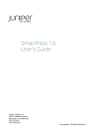
This guide describes how to install, configure, and service the ISG 2000. It presents
an example of a basic installation and configuration that secures resources in the
Trust and DMZ security zones, sets up a MGT zone for device administrators, and
defines a route-based VPN tunnel between the ISG 2000 and a remote peer (see
Figure 1). You can use this example as a reference as you perform similar tasks.
NOTE:
Intrusion Detection and Prevention (IDP) requires the installation of at least one
security module, an advanced license key, and an IDP license key. To configure
IDP on the ISG 2000, you must use NetScreen-Security Manager.
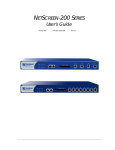
Figure 1: Example Configuration
Untrust Zone
LAN
10.2.2.0/24
Internet
ISP
Default GW: 1.1.1.2
DNS #1: 2.2.2.5
DNS #2: 2.2.2.6
1
POWER
STATUS
®
2
3
4
Remote Peer
UNTRUSTED
LINK/ACTIVIT
Y
10/100
ISP
VPN
Tunnel
ethernet1/1
1.1.1.1/30
DMZ
LAN
1.2.2.0/29
MGT Zone
10.2.2.0/28
Policies
MGT
10.2.2.1/28
PWR
ALARM
TEMP
STATUS
HA
FAN
MOD1
MOD2
MOD3
FLASH
ISG 2000
ethernet2/1
10.1.1.1/24
NAT mode
LAN
10.1.1.0/24
ethernet1/2
1.2.2.1/29
HTTP Server
www.jnpr.net
1.2.2.2:80
Mail Relay Server
smtp.jnpr.net
1.2.2.3:25
Note: The rook icon represents
a security zone interface.
Trust Zone
This guide makes the following assumptions:
You are adding the ISG 2000 to an existing network.
You have an account with an Internet service provider (ISP) that has provided
you with two sets of IP addresses:
An outside address in the ISP’s domain (1.1.1.1 in our example)
A range of addresses in your domain (such as 1.2.2.1–1.2.2.6)
You have a registered domain name (such as “jnpr.net”).
v
ISG 2000 User’s Guide
Content Summary
This guide contains the following chapters and appendix:
Chapter 1, “Configuring” provides instructions for making a console connection
to the ISG 2000, logging in, and performing a basic yet complete firewall and
VPN configuration.
Chapter 2, “Installing” provides instructions for cabling the ISG 2000 to the
network, mounting the device in a rack, and connecting the power supplies.
Chapter 3, “Hardware and Servicing” provides a detailed overview of the ISG
2000 and procedures for replacing interface modules, power supplies, and the
fan tray.
Appendix A, “Specifications” provides a list of physical specifications about the
ISG 2000, its modules, and its power supplies.
CLI Conventions
The following conventions are used when presenting the syntax of a command line
interface (CLI) command:
Anything inside square brackets [ ] is optional.
Anything inside braces { } is required.
If there is more than one choice, each choice is separated by a pipe ( | ). For
example,
set interface { ethernet1/1 | ethernet1/2 | ethernet2/1 } manage
means “set the management options for the ethernet1/1, ethernet1/2, or
ethernet2/1 interface”.
Variables appear in italic. For example:
set admin user name_str password pswd_str
When a CLI command appears within the context of a sentence, it is in bold
(except for variables, which are always in italic). For example: “Use the get
system command to display the serial number of a NetScreen device.”
NOTE:
vi
Content Summary
When typing a keyword, you only have to type enough letters to identify the word
uniquely. For example, typing set adm u joe p j12fmt54 is enough to enter the
command set admin user joe password j12fmt54. Although you can use this
shortcut when entering commands, all the commands documented here are
presented in their entirety.
:
Terminology
The following list contains acronyms and terminology used throughout this guide:
CLI
command line interface, a tool for configuring ScreenOS through a
console, Telnet, or secure shell (SSH) connection
DMZ
demilitarized zone, a predefined security zone for resources such as
Web servers to which you allow access from unknown hosts
function zone
a conceptual location for interfaces providing specific functionality,
such as device management access or high availability (HA) links
Global zone
a security zone without an interface that acts as a virtual storage
space for mapped IP (MIP) and virtual IP (VIP) addresses
hot swappable
able to be recognized by a system when connected and disconnected
without having to turn off and on the system
IDP
Intrusion Detection and Prevention, a technology for performing
deep packet inspection and taking preventive action
IKE
Internet Key Exchange, a protocol for securely yet publicly
negotiating keys to authenticate and encrypt/decrypt traffic
IPSec
Internet Protocol Security, a suite of related protocols for
cryptographically securing communications at the IP packet layer
license key
a key (in the form of an alphanumeric string) that unlocks features or
capacities within ScreenOS
MGT zone
a function zone from which administrators can connect to the ISG
2000 exclusively for management purposes
mini-GBIC
a gigabit interface converter that fits in a removable transceiver
NAT mode
an operational mode for Layer 3 interfaces that translates the source
IP address of packets
NetScreen-Security
Manager
a management application that configures and monitors multiple
devices over a local or wide area network (LAN or WAN) environment
Null zone
a virtual storage space for interfaces not bound to a zone
policy
a rule that permits, denies, rejects, or tunnels specified types of
traffic unidirectionally between two points
route-based VPN tunnel
a VPN tunnel bound to a tunnel interface to which a route points
Route mode
an operational mode for Layer 3 interfaces that routes IP packets
through the ISG 2000 without modifying the packet header content
security zone
a collection of one or more network segments requiring the
regulation of interzone and intrazone traffic through policies
ScreenOS
the operating system of the ISG 2000
Transparent mode
an operational mode for Layer 2 interfaces that forwards traffic like a
switch or bridge
Trust zone
a predefined security zone for protected network resources to which
you typically do not allow access from unknown hosts
tunnel interface
a logical interface that you bind to a route-based VPN tunnel
Untrust zone
a predefined security zone for unknown network hosts typically in a
WAN such as the Internet
WebUI
Web user interface, a graphical user interface for configuring
ScreenOS through a Web browser
Terminology
vii
ISG 2000 User’s Guide
IDP Requirements and Documentation
You can upgrade the ISG 2000 to support Intrusion Detection and Prevention (IDP)
and then use NetScreen-Security Manager to configure IDP on the device.
ISG 2000 Upgrade
To run IDP on the ISG 2000, you must set up the device as follows:
Upgrade the OS loader to v.1.1.5 or later.
Load the following license keys and firmware:
Advanced license key
IDP license key
ScreenOS 5.0.0-IDP1
Install at least one security module.
To obtain the upgrade kit and security modules, contact your value added reseller
(VAR). For information about upgrading the ISG 2000 to support IDP, refer to the
ISG 2000 Field Upgrade Guide, which is included in the ISG 2000 upgrade kit.
IDP Configuration through NetScreen-Security Manager
To configure IDP on the ISG 2000, you must use NetScreen-Security Manager 2004
FP3r3 or later.
NOTE:
NetScreen-Security Manager 2004 FP3r3 can operate on Solaris 9, Red Hat Linux
9.0, and Red Hat Enterprise Linux 3.0 operating systems.
For information on configuring IDP on the ISG 2000 through NetScreen-Security
Manager, refer to the following documentation:
NetScreen-Security Manager 2004 FP3-IDPr1 Installer's Guide – Instructions on
installing NetScreen-Security Manager
ISG 2000 Getting Started with IDP Guide – General instructions to help you get
started configuring IDP with NetScreen-Security Manager
IDP Deployment Strategies – Advanced IDP implementation scenarios
NetScreen-Security Manager 2004 FP3-IDPr1 Administrator's Guide – Complete
reference guide for NetScreen-Security Manager
NetScreen-Security Manager Online Help – Step-by-step configuration details
complementing the information in the administrator’s guide
The NetScreen-Security Manager documentation is available on the Juniper
Networks Web site: www.juniper.net/techpubs.
viii
IDP Requirements and Documentation
:
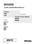
NetScreen Product Documentation Guide
To obtain technical documentation for Juniper Networks NetScreen products, see
the product documentation CD-ROM that ships with the ISG 2000.
Figure 2: NetScreen Product Documentation CD-ROM
NetScreen Concepts & Examples ScreenOS Reference Guide :
Extensive coverage of all major ScreenOS features, with
both conceptual background information and configuration
examples
NetScreen CLI Reference Guide : Compendium of all command
line reference (CLI) commands, with command syntax and
explanations of all keywords
NetScreen Messages Reference Guide : Collection of the
messages that appear in the event log, with their meanings
and recommended actions
Getting Started Guides and User’s Guides :
Platform-specific guides for connecting a
NetScreen device to a network and then
configuring it
Other Resources :
• FIPS-certified and Common Criteria-certified images and
documentation
• Help files
• SNMP MIB files
• Dictionary file for external authentication servers
• NetScreen device installation steps
• More …
You can also get documentation for the following Juniper Networks technologies
and products by visiting www.juniper.net/techpubs/:
NetScreen-Security Manager
Security devices
ScreenOS
NetScreen-Remote VPN client
Intrusion Detection and Prevention (IDP)
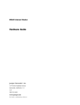
Another resource is the WebUI Help. When logged in to the ISG 2000 through the
WebUI, click the Help button to learn more about ScreenOS features:
Figure 3: WebUI Help
You can access context-sensitive Help by clicking the Help
button in the upper right corner of the WebUI …
… or by selecting Help > Online Help from the menu column.
The Help menu option also provides shortcuts to online
product registration and the NetScreen knowledgebase.
If you find any errors or omissions in this guide, please contact us at
[email protected], or complete and submit the documentation
feedback form at www.juniper.net/techpubs/docbug/docbugreport.html.
NetScreen Product Documentation Guide
ix
ISG 2000 User’s Guide
Technical Support
If you need any technical support, you can visit the Juniper Networks Customer
Support Center (CSC). There are many useful resources at the CSC, such as
NOTE:
A searchable knowledgebase containing solutions to over 2000 customer
questions
The latest ScreenOS firmware downloads
Release Notes are part of a firmware download.
To have access to CSC resources, you must first create a customer account and
register your NetScreen product. To set up such an account, go to
www.juniper.net/entitlement/setupAccountInfo.do and follow the online
instructions.
NOTE:
You need the serial number of the ISG 2000 to complete the account setup and
device registration.
After you have a customer account, you can create and submit technical support
cases for any product under warranty or with a valid support contract.
To open a support case, do the following:
1. Visit www.juniper.net/support.
2. In the Login to Support Center area, enter the user name and password that you
created while setting up your customer account.
3. Open a support case by clicking Case Management and then filling in the
online form. Include the output from the get tech and get license commands.
Also, if the network is complex, include a network diagram.
You can also open a support case by calling 1-888-314-JTAC (within the United
States) or 1-408-745-9500 (outside the United States).
x
Technical Support
Chapter 1
Configuring
This chapter describes how to make a console connection to the ISG 2000, log in,
and perform a basic configuration.
Table 1: Important Default Configuration Settings
Default MGT IP address: 192.168.1.1/24
Default ethernet IP addresses: 0.0.0.0/0
Default username: netscreen
Default password: netscreen
NOTE:
You must register your product at www.juniper.net/support/ so that you can
activate specific services, such as Intrusion Detection and Prevention (IDP).
After registering your product, purchase a license key from your value added
reseller (VAR), and then use NetScreen-Security Manager, the WebUI, or
the CLI to load the key. For information about registering your product and
obtaining and loading license keys, see the Fundamentals volume in the
NetScreen Concepts & Examples ScreenOS Reference Guide on the documentation
CD that ships with the ISG 2000.
This chapter includes the following main configuration sections:
NOTE:
“Before Beginning” on page 2
“Console Connection and Login” on page 3
“Basic Configuration” on page 4
“System Clock and Console Timeout” on page 5
“Admin Name and Password” on page 5
“Security Zones and Interfaces” on page 6
“DNS and Default Route” on page 12
“Policies” on page 13
“Intrusion Detection and Protection” on page 15
“IPSec VPN” on page 16
“Summary of CLI Commands” on page 19
“Returning the Device to Factory Default Settings” on page 21
For information on different configuration options such as virtual systems and
high availability, see the NetScreen Concepts & Examples ScreenOS Reference Guide.
1
ISG 2000 User’s Guide
Before Beginning
Before setting up the ISG 2000, you must make a few preparations.
1. Consider the network topology and the resources that you want to protect so
that you can decide where to put the ISG 2000. You want to make sure that all
traffic on which you want to enforce policies flows through the device. (A typical
network topology showing where to put the ISG 2000 is shown in Figure 1 on
page v, and on Figure 5 on page 4.)
2. Plan out the IP addresses and—where applicable—host.domain names that you
want each host to use. The devices in this guide use the following addresses:
ISG 2000
Untrust zone interface (ethernet1/1): 1.1.1.1/30
DMZ zone interface (ethernet1/2): 1.2.2.1/29
Trust zone interface (ethernet2/1): 10.1.1.1/24
MGT zone interface (MGT): 10.2.2.1/28
HTTP server: 1.2.2.2, www.jnpr.net
Mail relay server: 1.2.2.3, smtp.jnpr.net/pop3.jnpr.net
Trust zone hosts dynamically receive their addresses and DNS settings
from a stand alone DHCP server. Their default gateway is 10.1.1.1.
Network security administrators make an out-of-band connection to the
MGT interface on the ISG 2000. Their workstations are in the 10.2.2.0/28
subnet, completely separate from the rest of the network.
3. Obtain the IP addresses of the default gateway and external Domain Name
System (DNS) servers from the ISP. This guide uses the following addresses:
Default gateway: 1.1.1.2
Primary DNS server: 2.2.2.5
Secondary DNS server: 2.2.2.6
4. Communicate the IP addresses and host.domain names of the mail and web
servers to your ISP. After an ISP administrator adds this information to its DNS
servers, they can then answer DNS queries for them.
5. Ensure that the hosts in the Trust zone use 10.1.1.1 as their default gateway,
and that the servers in the DMZ use 1.2.2.1.
6. This guide assumes you configure the ISG 2000 through a console connection
from the serial port on your workstation to the console port on the ISG 2000.
You need the following:
VT100 terminal emulator such as Hilgraeve HyperTerminal installed on
your workstation (HyperTerminal is provided on all Windows operating
systems.)
The RJ-45 straight-through ethernet cable and DB9 adapter that ship with
the ISG 2000
Documentation CD that ships with the ISG 2000
For other device configuration methods, see the Administration volume in the
NetScreen Concepts & Examples ScreenOS Reference Guide.
NOTE:
2
Before Beginning
You must use NetScreen-Security Manager to configure Intrusion Detection and
Prevention (IDP) on the ISG 2000. See “Minimum Configuration for a
NetScreen-Security Manager Connection” on page 15.
Chapter 1: Configuring
Console Connection and Login
To begin configuring the ISG 2000, make a console connection between your
workstation and the ISG 2000 and run a vt100 terminal emulator program.
1. Connect the power cable to the ISG 2000 and turn on the power.
2. Connect the female end of the supplied DB-9 adapter to the serial port (or Com
port) of your workstation.
3. Connect one end of the RJ-45 ethernet cable into the console port of the ISG
2000 and the other end of the cable to the DB-9 adapter.
Figure 4: Console Connection
Rear of Workstation
PWR
ALARM
TEMP
STATUS
HA
FAN
MOD1
MOD2
MOD3
FLASH
ISG 2000
Connect the Rj-45 ethernet
cable to the console port.
Plug the DB-9 adapter into the serial port,
and then connect the ethernet cable to the adapter.
4. Start a serial terminal emulation session. Use the following settings:
Baud Rate to 9600
Parity to No
Data Bits to 8
Stop Bit to 1
Flow Control to none
5. Press the Enter key to see the login prompt.
6. At the login prompt, enter netscreen
7. At the password prompt, enter netscreen
NOTE:
The login (admin name) and password are both case-sensitive. To change the login
name and password, see “Admin Name and Password” on page 5.
Console Connection and Login
3
ISG 2000 User’s Guide
Basic Configuration
The following sections contain the CLI commands for setting up the ISG 2000 as a
firewall and VPN termination point for the network shown in Figure 5. By entering
these commands, you can perform a basic configuration of the ISG 2000 so that it
can perform firewall and VPN functions.
Figure 5: Basic Firewall and VPN Configuration
The NetScreen-ISG 2000 permits
selected traffic between zones.
A route-based VPN tunnel provides
secure bidirectional traffic between
the NetScreen-ISG 2000 and a remote peer.
Untrust Zone
LAN
10.2.2.0/24
Internet
ISP
Default GW: 1.1.1.2
DNS #1: 2.2.2.5
DNS #2: 2.2.2.6
1
POWER
STATUS
®
2
3
4
Remote Peer
UNTRUSTED
LINK/ACTIVIT
Y
10/100
ISP
VPN
Tunnel
ethernet1/1
1.1.1.1/30
DMZ
LAN
1.2.2.0/29
MGT Zone
10.2.2.0/28
Policies
MGT
10.2.2.1/28
PWR
ALARM
TEMP
STATUS
HA
FAN
MOD1
MOD2
MOD3
FLASH
ISG 2000
ethernet2/1
10.1.1.1/24
NAT mode
LAN
10.1.1.0/24
Trust Zone
4
Basic Configuration
ethernet1/2
1.2.2.1/29
HTTP Server
www.jnpr.net
1.2.2.2:80
Mail Relay Server
smtp.jnpr.net
1.2.2.3:25
Note: The rook icon represents
a security zone interface.
Chapter 1: Configuring
System Clock and Console Timeout
You need to set the system clock so that the event log entries have the correct
date/time stamps. Also, the correct date/time is essential if the device has to check
the validity of digital certificates.
You can also change the timeout value for an idle console connection. By default,
the ISG 2000 automatically closes a console connection if it is idle for 10 minutes.
You can change this to a higher or lower interval, or disable the timeout completely.
1. Set the system clock with the following command:
set clock dd/mm/yyyy hh:mm:ss
where dd/mm/yyyy = day/month/year, and hh:mm:ss = hour/minute/second
(for example: 07/15/2005 16:40:55).
save
After you enter the save command, the ISG 2000 saves the current
configuration to flash memory. If you reset the device without saving the latest
configuration, the ISG 2000 loads the previously saved configuration.
NOTE:
To see other options for setting the system clock, refer to the Fundamentals
volume in the NetScreen Concepts & Examples ScreenOS Reference Guide.
2. (Optional) By default, the console times out and terminates automatically after
10 minutes of idle time. To change this timeout interval, enter the following:
set console timeout number
save
where number is the length of idle time in minutes before session termination.
To prevent any automatic termination, specify a value of 0. This setting is
convenient for performing an initial configuration, but Juniper Networks does
not recommend permanently disabling the console timeout.
Admin Name and Password
Because all NetScreen products use the same admin name and password
(netscreen), it is highly advisable to change your login information immediately. To
change your login information, enter the following commands:
set admin name name_str
set admin password pswd_str
save
NOTE:
For information on creating multiple administrators with different administrative
levels, refer to the Administration volume in the NetScreen Concepts & Examples
ScreenOS Reference Guide.
If you want to return the ISG 2000 to its default configuration (including the default
login name and password), see “Returning the Device to Factory Default Settings”
on page 21.
System Clock and Console Timeout
5
ISG 2000 User’s Guide
Security Zones and Interfaces
A security zone is a collection of one or more network segments requiring the
regulation of inbound and outbound traffic through policies. You use security zones
to separate network segments of differing trust levels and control the flow of traffic
between them by the policies that you set.
Figure 6: Three Security Zones
Three security zones requiring interzone policies
for traffic to flow from one zone to another.
The security zones can be Layer 3
zones or Layer 2 zones.
Security Zone
Policies
PWR
ALARM
TEMP
STATUS
HA
FAN
MOD1
MOD2
MOD3
FLASH
Security Zone
ISG 2000
Security Zone
The ISG 2000 ships with seven predefined security zones—including the Global
zone, which is used mainly for holding mapped IP (MIP) and virtual IP (VIP)
addresses. For information on all zone types and their uses, see the Fundamentals
volume in the NetScreen Concepts & Examples ScreenOS Reference Guide.
To view all the predefined zones, enter the get zone command, as shown below.
get zone
Total 13 zones created in vsys Root - 7 are policy configurable.
Total policy configurable zones for Root is 7.
6
Security Zones and Interfaces
ID
Name
Type
Attr
VR
Default-IF
VSYS
0
Null
Null
Shared
untrust-vr
hidden
Root
1
Untrust
Sec(L3)
Shared
trust-vr
null
Root
2
Trust
Sec(L3)
trust-vr
null
Root
3
DMZ
Sec(L3)
trust-vr
null
Root
4
Self
Func
trust-vr
self
Root
5
MGT
Func
trust-vr
mgt
Root
6
HA
Func
trust-vr
null
Root
10
Global
Sec(L3)
trust-vr
null
Root
11
V1-Untrust
Sec(L2)
trust-vr
v1-untrust
Root
12
V1-Trust
Sec(L2)
trust-vr
v1-trust
Root
13
V1-DMZ
Sec(L2)
trust-vr
v1-dmz
Root
14
VLAN
Func
trust-vr
vlan1
Root
16
Untrust-Tun
Tun
trust-vr
hidden.1
Root
Chapter 1: Configuring
There are three predefined security zones for interfaces operating at the Network
Layer (Layer 3) in the Open Systems Interconnection (OSI) Model and three
predefined security zones for interfaces operating at the Data Link Layer (Layer 2):
Predefined Layer 3 security zones: Untrust, Trust, and DMZ
Predefined Layer 2 security zones: V1-Untrust, V1-Trust, and V1-DMZ
The example in this guide uses the three predefined Layer 3 security zones.
Figure 7: Untrust, DMZ, and Untrust Security Zones
Untrust Zone
This zone typically contains the public
network that the NetScreen-ISG 2000
protects against.
DMZ Zone
PWR
ALARM
TEMP
STATUS
HA
FAN
MOD1
MOD2
MOD3
FLASH
ISG 2000
This zone typically contains
your public-facing resources,
such as web servers.
Trust Zone
This zone typically contains your
protected internal resources.
Note: This illustration shows the typical uses of each zone. However, this arrangement is
not compulsory. You can customize their uses to best suit your network environment.
You can define more security zones by using the following command:
set zone name zone [ l2 id_num ]
For information on creating zones, see the chapter on zones in the Fundamentals
volume in the NetScreen Concepts & Examples ScreenOS Reference Guide.
Security Zones and Interfaces
7
ISG 2000 User’s Guide
Binding Interfaces to Zones
The ISG 2000 supports different types of interface modules in four interface module
bays. The leftmost interface in the module in the upper left bay is ethernet1/1. The
interface to the right of ethernet1/1 is ethernet1/2. If there are more interfaces in
that module, they are numbered ethernet1/3, ethernet1/4, and so on. As you can
see, the first number represents the position of the interface module in one of the
four bays, and the second number represents the position of the interface in that
module from left to right.
Figure 8: Interface Numbers
Interface Module Bays
1
3
2
4
e1/1
e1/2
e2/1
e2/2
e1/3
e1/4
e3/1
e3/2
e4/1
e4/2
e4/3
e4/4
As you can see in the output from the get interface command below, none of the
interface module interfaces are prebound to a security zone. They are all in the Null
zone.
get interface
A - Active, I - Inactive, U - Up, D - Down, R - Ready
Interfaces in vsys Root:
8
Security Zones and Interfaces
Name
IP Address
Zone
MAC
VLAN State VSD
mgt
192.168.1.1/24
MGT
0010.db58.bb80
–
D
–
eth1/1
0.0.0.0/0
Null
0010.db58.bb87
–
D
–
eth1/2
0.0.0.0/0
Null
0010.db58.bb88
–
D
–
eth1/3
0.0.0.0/0
Null
0010.db58.bb89
–
D
–
eth1/4
0.0.0.0/0
Null
0010.db58.bb8a
–
D
–
eth2/1
0.0.0.0/0
Null
0010.db58.bb9d
–
D
–
eth2/2
0.0.0.0/0
Null
0010.db58.bb9e
–
D
–
eth3/1
0.0.0.0/0
Null
0010.db58.bb8d
–
D
–
eth3/2
0.0.0.0/0
Null
0010.db58.bb8e
–
D
–
eth4/1
0.0.0.0/0
Null
0010.db58.bb81
–
D
–
eth4/2
0.0.0.0/0
Null
0010.db58.bb82
–
D
–
eth4/3
0.0.0.0/0
Null
0010.db58.bb83
–
D
–
eth4/4
0.0.0.0/0
Null
0010.db58.bb84
–
D
–
vlan1
0.0.0.0/0
VLAN
0010.db58.bb8f
1
D
–
Chapter 1: Configuring
NOTE:
The interface names that appear in the get interface output depend on the type
of interface modules installed in the ISG 2000. Most likely the output you see
differs from that shown here.
Before you can make use of an interface, you must bind it to a security zone. The
interface then becomes a point of ingress and egress for traffic to and from that
zone. You can bind a single interface to only one security zone, although that one
zone can support multiple different interfaces. To bind an interface to a zone, use
the following command:
set interface interface zone zone
in which interface and zone are the names of the objects you want to bind together.
For example:
set interface ethernet1/1 zone untrust
set interface ethernet1/2 zone dmz
set interface ethernet2/1 zone trust
save
Figure 9: Interfaces Bound to Security Zones
Untrust Zone
ethernet1/1
DMZ Zone
ethernet1/2
PWR
ALARM
TEMP
STATUS
HA
FAN
MOD1
MOD2
MOD3
FLASH
ISG 2000
ethernet2/1
Trust Zone
Note: The rook icon represents
a security zone interface.
Interface Modes
An ISG 2000 security zone interface can operate in one of three modes: NAT mode,
Route mode, or Transparent mode. NAT mode and Route mode operate at the
Network Layer (Layer 3) in the OSI Model. Transparent mode operates at the Data
Link Layer (Layer 2). Although some interfaces can function in NAT mode while
others concurrently function in Route mode—both modes operating at Layer 3—
the ISG 2000 does not support different interfaces operating concurrently at Layer 3
and Layer 2.
Layer 3 (Route mode and NAT mode) – When you bind an interface to a Layer 3
security zone and give it an IP address, it can operate in either NAT or Route mode.
When an interface is in NAT mode, the NetScreen device translates the source IP
address and source port number on all packets arriving at that interface. When an
interface is in Route mode, the NetScreen device performs Layer 3 routing
operations without modifying the source IP address or port number.
Security Zones and Interfaces
9
ISG 2000 User’s Guide
When you bind an interface to a Layer 2 security zone, it does not have an IP
address and operates in Transparent mode. The NetScreen device forwards traffic
arriving at an interface in Transparent mode essentially like a Layer 2 bridge. That
is, the NetScreen device uses the MAC address in the Layer 2 header to forward
traffic out onto another segment in the same broadcast domain.
By default, no ISG 2000 security zone interfaces have IP addresses and all are in the
Null zone. The Null zone is a function zone that holds interfaces until you bind them
to a security zone. To make a security zone interface operational, you must bind it
to a security zone and, if it is a Layer 3 security zone, assign it an IP address.
NOTE:
For more information about interface modes, see the chapter on interface modes
in the Fundamentals volume in the NetScreen Concepts & Examples ScreenOS
Reference Guide.
Configuring Interfaces
After you bind an interface to a security zone, you can assign it an IP address. and
configure other settings for that interface. To assign an IP address to an interface,
use the following command:
set interface interface ip ip_addr/netmask
where interface is the name of the interface, and ip_addr/netmask is the IP address
and netmask that you assign it.
To set management options on an interface, use the following command:
set interface interface manage [ ident-reset | ping | snmp | ssh | ssl | telnet | web ]
in which you can specify one or none of the options following the keyword
manage. If you enter just set interface interface manage, the command enables all
the interface options except ident-reset. If you want to enable a subset of all the
options, you can repeatedly enter the command, each time specifying a different
management option.
Untrust Zone Interface
In our example, ethernet1/1 is bound to the Untrust zone. The ISP provided the
address for this interface: 1.1.1.1/30. Because this interface is going to face
unknown and potentially malicious entities in the public network, you do not
enable any management options on this interface.
set interface ethernet1/1 ip 1.1.1.1/30
save
To review the settings for ethernet1/1, enter the following command:
get interface ethernet1/1
This command produces the following output:
Interface ethernet1/1:
number 7, if_info 57400, if_index 0, mode route
link up, phy-link up/full-duplex
10
Security Zones and Interfaces
Chapter 1: Configuring
vsys Root, zone Untrust, vr trust-vr
*ip 1.1.1.1/30 mac 0010.db58.bb87
*manage ip 1.1.1.1, mac 0010.db58.bb87
route-deny disable
ping disabled, telnet disabled, SSH disabled, SNMP disabled
web disabled, ident-reset disabled, SSL disabled
webauth disabled, webauth-ip 0.0.0.0
OSPF disabled BGP disabled RIP disabled
bandwidth: physical 100Mbps, configured 0Mbps
DHCP-Relay disabled
DMZ Interface
In our example, ethernet1/2 is bound to the DMZ. The ISP also provided you with a
range of addresses to use with the jnpr.net domain. This interface leads to the
public-facing web server and mail relay server, so you do not enable any
management options on this interface either.
set interface ethernet1/2 ip 1.2.2.1/29
save
In the same way that you reviewed the settings for ethernet1/1, you can use the get
interface ethernet1/2 command to review these settings also.
Trust Zone Interface
In our example, ethernet2/1 is bound to the Trust zone. The Trust zone uses private
IP addresses. These addresses cannot be used on a public network such as the
Internet. Therefore, when hosts in this zone initiate traffic to a public network, the
ISG 2000 uses network address translation (NAT) to translate their private addresses
to a public address in the IP packet header. In our example, the ISG 2000 translates
the private addresses to the address of the Untrust zone interface. Use the following
commands:
set interface ethernet2/1 ip 10.1.1.1/24
set interface ethernet2/1 nat
save
NOTE:
ScreenOS offers several approaches to address translation. To learn about the
available options, refer to the NetScreen Concepts & Examples ScreenOS Reference
Guide.
You can enter get interface ethernet2/1 to review the Trust zone interface settings.
MGT Interface
The MGT interface is prebound to the MGT zone. This zone is a function zone
different from a security zone. The MGT interface receives management traffic
exclusively, unlike a security zone interface that can receive management traffic
while receiving and forwarding network user traffic. Because the MGT interface is
completely separate from network user traffic, it is more secure and reliable. Even
during times when network user traffic is heavy, you can maintain connectivity for
your management traffic by keeping it completely separate, or out-of band.
Security Zones and Interfaces
11
ISG 2000 User’s Guide
To use the MGT interface, connect an ethernet cable from the MGT interface to a
switch or router that leads to an exclusive segment of the network containing only
the ISG 2000 administrators’ workstations. Then give the MGT interface an address
that is reachable from that network segment.
The default IP address/netmask for the MGT interface is 192.168.1.1 /24. Because
this address has been widely published, Juniper Networks strongly recommends
that you change it.
In our example, you assign the MGT interface the IP address 1.2.2.1/28. Use the
following command:
set interface mgt ip 1.2.2.1/28
The network security administrators in our example are going to access the ISG
2000 from workstations in the MGT zone. You want them to be able to use Telnet,
SSH, and HTTP only. You also want them to be able to ping the MGT interface.
By default, all options except ident-reset are enabled on the MGT interface.
Therefore, use the following commands to disable the management options that
you do not want the administrators to use:
unset interface mgt manage snmp
unset interface mgt manage ssl
save
Enter the get interface mgt command to review the MGT interface settings.
DNS and Default Route
When you enter the DNS server IP addresses that you receive from your ISP, the
NetScreen device can resolve domain names that you use in your configuration,
such as addresses in policies or IKE gateways. To enter addresses for the two DNS
servers in our example, use the following commands:
set dns host dns1 2.2.2.5
set dns host dns1 2.2.2.6
save
When the ISG 2000 receives a static IP address, the ISP also provides the IP address
of the default gateway to which the ISG 2000 sends traffic destined for addresses for
which there are no specific routes. It is important that the ISG 2000 has a default
route pointing to this gateway. To enter the address of the default gateway in our
example, use the following command:
set vrouter trust-vr route 0.0.0.0/0 interface ethernet1/1 gateway 1.1.1.2
save
NOTE:
12
DNS and Default Route
The ISG 2000 supports a large number of routing environments. For information
about configuring routing on the device, refer to the Routing volume in the
NetScreen Concepts & Examples ScreenOS Reference Guide.
Chapter 1: Configuring
Policies
By default, the ISG 2000 does not allow any traffic between zones. To permit traffic
to cross the firewall, you must create policy that specifically permits one or more
services to pass from hosts in one zone to others in another zone. Because the ISG
2000 performs stateful inspection, you do not need to define a policy to permit
return traffic. The ISG 2000 maintains a session table that matches responses to
requests and thereby determines which traffic arriving at a particular interface does
or does not belong to an existing session.
The command syntax for the core elements of a policy is as follows:
set policy from src_zone to dst_zone src_addr dst_addr service { permit | deny |
reject | tunnel }
NOTE:
For a complete explanation of all the elements that you can use when creating a
policy, see the chapter on policies in the Fundamentals volume in the NetScreen
Concepts & Examples ScreenOS Reference Guide.
Addresses
You can use the predefined address “any” to indicate all hosts in a particular
zone—either the source or destination zone. To use a more restrictive source or
destination address, you must define one, using the following command:
set address zone name { ip_addr/netmask | [ host. ] domainname }
For example:
set address dmz web1 1.2.2.2/32
or
set address dmz web1 www.jnpr.net
You can also put a set of addresses together to form a group. Use the following
command:
set group address zone name add name_str
NOTE:
For information about creating and grouping addresses, see the section on
addresses in the NetScreen Concepts & Examples ScreenOS Reference Guide.
Services
There are over 100 predefined services that you can use when creating policies. You
can use the predefined service “any” to indicate any type of traffic. You can group
services together to apply a policy to all the services in that group. Also, you can
create custom services.
To create a service group, use the following command, repeating it with the same
group name and different service names:
set group service name add service
Policies
13
ISG 2000 User’s Guide
To create a custom service using the TCP or UDP protocols, use the following
command:
set service name protocol { tcp | udp } [ src-port number-number ] dst-port
number-number [ timeout number ]
NOTE:
For information about creating and grouping services, see the section on services
in the NetScreen Concepts & Examples ScreenOS Reference Guide.
In our example, you need to create the following addresses and policies:
set address dmz web1 1.2.2.2/32
set address dmz mail-relay 1.2.2.3/32
set address trust mail1 10.1.1.4/32
set policy id 1 from trust to dmz mail1 mail-relay mail permit log count
set policy id 2 from trust to dmz any web1 http permit log count
set policy id 3 from trust to untrust any any any permit log count
set policy id 4 from dmz to trust mail-relay mail1 mail permit log count
set policy id 5 from dmz to untrust mail-relay any mail permit log count
set policy id 6 from untrust to dmz any web1 http permit log count
set policy id 7 from untrust to dmz any mail-relay mail permit log count
save
The keyword log instructs the ISG 2000 to create entries in its traffic log for all
traffic to which the policy applies. The keyword “count” instructs the ISG 2000 to
keep a running tally of the number of bytes to which the policy applies. Both of
these options provide useful tools when analyzing traffic patterns and diagnosing
problems.
To view the policies that you have created, use the get policy command:
get policy
Total regular policies 7, Default deny.
ID From
To
Src-address Dst-address Service Action State
ASTLCB
1
Trust
DMZ
mail1
mail-relay
MAIL
Permit
enabled
---XXX
2
Trust
DMZ
Any
web1
HTTP
Permit
enabled
---XXX
3
Trust
Untrust Any
Any
ANY
Permit
enabled
---XXX
4
DMZ
Trust
mail1
MAIL
Permit
enabled
---XXX
5
DMZ
Untrust mail-relay
Any
MAIL
Permit
enabled
---XXX
6
Untrust DMZ
Any
web1
HTTP
Permit
enabled
---XXX
7
Untrust DMZ
Any
mail-relay
MAIL
Permit
enabled
---XXX
mail-relay
The order of policies in the list determines the order in which the ISG 2000 applies
them. The ISG 2000 first notes the five-part tuple of source and destination zone,
source and destination address, and service in a packet arriving atone of its
interfaces. It then searches for a policy whose components match all five parts of
the tuple by starting at the top of the list and continuing down until it finds a match.
If it does not find a match, it drops the packet.
14
Policies
Chapter 1: Configuring
Intrusion Detection and Protection
Intrusion Detection and Protection (IDP) is a mechanism for filtering the traffic
permitted by firewall policies. IDP uses a variety of techniques such as examining
Layer 3 and 4 packet headers and Layer 7 application content and protocol
characteristics in an effort to detect and prevent any attacks or anomalous behavior
that might be present in permitted traffic.
NOTE:
For more information about IDP, see the ISG 2000 Getting Started with IDP Guide.
You can use NetScreen-Security Manager, the WebUI, or the CLI to install an IDP
license key, but to configure IDP for the ISG 2000, you must use NetScreen-Security
Manager.
NOTE:
When you install an IDP license key, the ISG 2000 automatically disables Deep
Inspection (DI).
Minimum Configuration for a NetScreen-Security Manager Connection
Before you can manage the ISG 2000 with NetScreen-Security Manager, you need to
set up the ISG 2000 on the network so that NetScreen-Security Manager can
connect to it. At a minimum, you need to configure the following on the ISG 2000:
Set an IP address for the interface through which NetScreen-Security Manager
can connect to the ISG 2000.
If there is a network forwarding device between the ISG 2000 and the
NetScreen-Security Manager server, set a route through that device to the server.
Enable the ISG 2000 for management from NetScreen-Security Manager. This is
enabled by default.
For example, to set up the ISG 2000 for NetScreen-Security Manager to connect to it
through ethernet1/1, do the following:
Cable the ISG 2000 to the network as described in “Connecting the Device to a
Network” on page 24
Log in to the device, and then enter the following commands:
set interface ethernet1/1 zone untrust
set interface ethernet1/1 ip 1.1.1.1/30
set vrouter trust-vr route 0.0.0.0/0 interface ethernet1/1 gateway 1.1.1.2
set nsm enable
save
You can now connect to the ISG 2000 through ethernet1/1 from NetScreen-Security
Manager and continue configuring the device.
Intrusion Detection and Protection
15
ISG 2000 User’s Guide
IPSec VPN
This section presents a configuration for a route-based VPN tunnel between the ISG
2000 and a remote peer with a dynamically assigned IP address. The NetScreen
device at the remote peer site is a NetScreen-5GT in Trust-Untrust mode. Because it
receives its address dynamically through PPPoE or DHCP, Phase 1 negotiations
must be in aggressive mode. The tunnel configuration uses the following elements:
Tunnel interface: tunnel.1 in Untrust zone
Outgoing interface:
ISG 2000: ethernet1/1
NetScreen-5GT: Untrust
Phase 1 exchange mode: Aggressive
Phase 1 and Phase 2 proposal security levels: Compatible
Proxy IDs: local 0.0.0.0/0; remote 0.0.0.0/0; service ANY
Preshared key: Iwb715iSF
IKE ID for remote peer: [email protected]
Figure 10: IPSec VPN Tunnel
Trust Zone
ethernet2/1
10.1.1.1/24
ethernet1/1
1.1.1.1/30
Tunnel Interface
tunnel.1
NetScreen-ISG 2000
10.1.1.0/24
VPN Tunnel: vpn1
Agressive Mode
Security Level for P1 and P2:
Compatible
IKE ID for NetScreen-5GT:
[email protected]
Preshared Key: Iwb715iSF
Untrust Zone
1
POWER
®
PWR
ALARM
TEMP
STATUS
HA
FAN
MOD1
MOD2
MOD3
FLASH
ISG 2000
Internet
Untrust Zone
NOTE:
STATUS
2
3
4
UNTRUSTED
LINK/ACTIVIT
Y
10/100
10.2.2.0/24
NetScreen-5GT
Tunnel Interface
tunnel.1
unnumbered
Untrust Interface
Dynamically
Assigned
IP Address
Trust Interface
10.2.2.1/24
Trust Zone
NetScreen ScreenOS offers a rich variety of options for IPSec VPN tunnels. For
information about the many available options, refer to the VPNs volume in the
NetScreen Concepts & Examples ScreenOS Reference Guide.
The VPN tunnel configuration for the NetScreen devices at both ends is provided.
16
IPSec VPN
Chapter 1: Configuring
ISG 2000
1. Create a tunnel interface and bind it to the Untrust zone. It is unnecessary for
the tunnel interface to have a unique IP address, so you define it as
“unnumbered” and borrow the IP address from ethernet1/1.
set interface tunnel.1 zone untrust
set interface tunnel.1 ip unnumbered interface ethernet1/1
2. Create addresses for the local and remote networks for later use in policies.
set address trust local 10.1.1.0/24
set address untrust peer1 10.2.2.0/24
3. Define the following settings for dynamic IKE gateway “gw1”:
Define the peer’s IKE ID. This is a string that the peer sends during Phase 1
negotiations to identify itself.
Define the preshared key that both IKE peers use when generating keying
material.
Specify the outgoing interface from which the ISG 2000 sends IKE traffic
when performing Phase 1 and 2 negotiations.
Define the security level for Phase 1 proposals as “Compatible”. This set
includes the following four Phase 1 proposals, each of which has a lifetime
of 28,800 seconds (or 8 hours). When the lifetime expires, the ISG 2000
renegotiates Phase 1 with its peer.
pre-g2-3des-sha
pre-g2-3des-md5
pre-g2-des-sha
pre-g2-des-md5
set ike gateway peer1 dynamic [email protected] aggressive outgoing-interface
ethernet1/1 preshare Iwb715iSF sec-level compatible
4. Define the following settings for IPSec VPN tunnel “vpn1”:
Define the security level for Phase 2 negotiations as “Compatible”. This set
includes the following four Phase 2 proposals, each of which has a lifetime
of 3600 seconds (or 1 hour). When the lifetime expires, the ISG 2000
renegotiates Phase 2—and possibly Phase 1 also—with its peer.
nopfs-esp-3des-sha
nopfs-esp-3des-md5
nopfs-esp-des-sha
nopfs-esp-des-md5
set vpn vpn1 gateway peer1 tunnel sec-level compatible
Bind the IKE gateway “gw1” to the VPN tunnel.
set vpn vpn1 bind interface tunnel.1
Set the proxy ID, which specifies the local and remote IP addresses and the
service that you want to pass through the tunnel. Setting the proxy ID as
0.0.0.0-0.0.0.0-ANY imposes no restrictions, allowing you to control the
traffic flow at the policy level.
set vpn vpn1 proxy-id local-ip 0.0.0.0/0 remote-ip 0.0.0.0/0 any
IPSec VPN
17
ISG 2000 User’s Guide
5. Set a route to the remote peer’s network through tunnel.1. Also set a null route
to the peer’s network with a less preferable metric. If the route through tunnel.1
becomes unavailable, the ISG 2000 then uses the null route, sending traffic for
the remote peer to the null interface, which effectively drops it. If tunnel.1 goes
down, the route associated with it becomes inactive. If there is no null route,
the ISG 2000 might use the default route and send unprotected traffic out
ethernet1/1. Creating a null route obviates such an unwanted occurrence.
set vrouter trust-vr route 10.2.2.0/24 interface tunnel.1
set vrouter trust-vr route 10.2.2.0/24 interface null metric 10
6. Create a pair of policies permitting traffic to flow bidirectionally between the
two sites.
set policy id 8 top from untrust to trust peer1 local any permit
set policy id 9 top from trust to untrust local peer1 any permit
save
Remote Peer
After the administrator at the remote site sets up the NetScreen-5GT, he can then
enter the following commands to configure that end of the VPN tunnel:
set
set
set
set
set
interface tunnel.1 zone untrust
interface tunnel.1 ip unnumbered interface untrust
address trust local 10.2.2.0/24
address untrust peer1 10.1.1.0/24
ike gateway gw1 address 1.1.1.1 aggressive local-id [email protected]
outgoing-interface untrust preshare Iwb715iSF sec-level compatible
set vpn vpn1 gateway gw1 tunnel sec-level compatible
set vpn vpn1 bind interface tunnel.1
set vpn vpn1 proxy-id local-ip 10.2.2.0/24 remote-ip 10.1.1.0/24 any
set vrouter trust-vr route 0.0.0.0/0 interface untrust
set vrouter trust-vr route 10.2.2.0/24 interface tunnel.1
set vrouter trust-vr route 10.2.2.0/24 interface null metric 10
set policy id 1 top from untrust to trust peer1 local any permit
set policy id 2 top from trust to untrust local peer1 any permit
save
18
IPSec VPN
Chapter 1: Configuring
Summary of CLI Commands
The following sets of commands include all the CLI commands used in the example
configuration featured in the previous sections in this chapter. The section in which
each type of command is described is also provided.
CLI Commands – Example Firewall Configuration
Commands
Descriptions
set clock dd/mm/yyyy hh:mm:ss
set console timeout number
“System Clock and Console
Timeout” on page 5
set admin name name_str
set admin password pswd_str
“Admin Name and Password”
on page 5
set interface ethernet1/1 zone untrust
set interface ethernet1/2 zone dmz
set interface ethernet2/1 zone trust
set interface ethernet1/1 ip 1.1.1.1/30
set interface ethernet1/2 ip 1.2.2.1/29
set interface ethernet2/1 ip 10.1.1.1/24
set interface ethernet2/1 nat
set interface mgt ip 1.2.2.1/28
“Security Zones and
Interfaces” on page 6
set dns host dns1 2.2.2.5
set dns host dns1 2.2.2.6
set vrouter trust-vr route 0.0.0.0/0 interface
ethernet1/1 gateway 1.1.1.2
“DNS and Default Route” on
page 12
set address dmz web1 1.2.2.2/32
set address dmz mail-relay 1.2.2.3/32
set address trust mail1 10.1.1.4/32
“Addresses” on page 13
set policy id 1 from trust to dmz mail1 mail-relay
mail permit log count
set policy id 2 from trust to dmz any web1 http
permit log count
set policy id 3 from trust to untrust any any any
permit log count
set policy id 4 from dmz to trust mail-relay mail1
mail permit log count
set policy id 5 from dmz to untrust mail-relay any
mail permit log count
save
“Policies” on page 13
Summary of CLI Commands
19
ISG 2000 User’s Guide
CLI Commands – Example Route-Based VPN Configuration
ISG 2000 Commands
Description
set interface tunnel.1 zone untrust
set interface tunnel.1 ip unnumbered interface
ethernet2/1
“ISG 2000” on page 17
set address trust local 10.1.1.0/24
set address untrust peer1 10.2.2.0/24
set ike gateway peer1 dynamic [email protected]
aggressive outgoing-interface ethernet2/1 preshare
Iwb715iSF proposal pre-g2-3des-sha
set vpn vpn1 gateway peer1 tunnel sec-level compatible
set vpn vpn1 bind interface tunnel.1
set vpn vpn1 proxy-id local-ip 0.0.0.0/0 remote-ip
0.0.0.0/0 any
set vrouter trust-vr route 10.2.2.0/24 interface tunnel.1
set vrouter trust-vr route 10.2.2.0/24 interface null
metric 10
set policy id 8 top from untrust to trust peer1 local any
permit
set policy id 9 top from trust to untrust local peer1 any
permit
save
Remote Peer Commands
Description
set interface tunnel.1 zone untrust
set interface tunnel.1 ip unnumbered interface untrust
“Remote Peer” on page 18
set address trust local 10.2.2.0/24
set address untrust peer1 10.1.1.0/24
set ike gateway gw1 address 1.1.1.1 aggressive local-id
[email protected] outgoing-interface untrust preshare
Iwb715iSF proposal pre-g2-3des-sha
set vpn vpn1 gateway gw1 tunnel sec-level compatible
set vpn vpn1 bind interface tunnel.1
set vpn vpn1 proxy-id local-ip 0.0.0.0/0 remote-ip
0.0.0.0/0 any
set vrouter trust-vr route 0.0.0.0/0 interface untrust
set vrouter trust-vr route 10.2.2.0/24 interface tunnel.1
set vrouter trust-vr route 10.2.2.0/24 interface null
metric 10
set policy id 1 top from untrust to trust peer1 local any
permit
set policy id 2 top from trust to untrust local peer1 any
permit
save
20
Summary of CLI Commands
Chapter 1: Configuring
Returning the Device to Factory Default Settings
If you want to return the ISG 2000 to its default settings, you can do either of the
following, depending on whether or not your are logged in:
If you are logged in, you can enter the following sequence of commands:
unset all
The following prompt appears: “Erase all system config, are you sure y / [n]?”
Press the Y key.
The system configuration is returned to the factory default settings.
reset
The following prompt appears: “Configuration modified, save? [y] / n”
Press the N key.
The following prompt appears: “System reset, are you sure? y / [n] n”
Press the Y key.
The system reboots.
If you lose your admin name or password, you can use the following procedure
to reset the NetScreen device to its default settings. This destroys any existing
configurations but restores access to the device. To perform this operation, you
need to make a console connection, as described in “Console Connection and
Login” on page 3.
1. At the login prompt, type the serial number of the device.
2. At the password prompt, type the serial number again.
The following message appears:
!!! Lost Password Reset !!! You have initiated a command to reset the
device to factory defaults, clearing all current configuration and
settings. Would you like to continue? y/[n]
3. Press the Y key.
The following message appears:
!! Reconfirm Lost Password Reset !! If you continue, the entire
configuration of the device will be erased. In addition, a permanent
counter will be incremented to signify that this device has been reset.
This is your last chance to cancel this command. If you proceed, the
device will return to factory default configuration, which is: System IP:
192.168.1.1; username: netscreen; password: netscreen. Would you
like to continue? y/[n]
4. Press the Y key to reset the device.
You can now log in using netscreen as the default admin name and
password.
NOTE:
By default the device recovery feature is enabled. You can disable it by entering
the following CLI command: unset admin device-reset
Returning the Device to Factory Default Settings
21
ISG 2000 User’s Guide
22
Returning the Device to Factory Default Settings
Chapter 2
Installing
This chapter describes how to cable the ISG 2000 to the network and install it in an
equipment rack. Topics in this chapter include:
“Connecting the Device to a Network” on page 24
“Equipment Rack Mounting” on page 26
“Equipment Rack Installation Guidelines” on page 26
“Equipment Rack Accessories and Required Tools” on page 26
“Rear-and-Front Mount” on page 27
“Mid-Mount” on page 28
Observing the following precautions can prevent injuries, equipment failures, and
shutdowns.
NOTE:
Never assume that the power supply is disconnected from a power source.
Always check first.
Room temperature might not be sufficient to keep equipment at acceptable
temperatures without an additional circulation system. Ensure that the room in
which you operate the device has adequate air circulation.
Do not work alone if potentially hazardous conditions exist, especially when
mounting the device in a rack.
Do not lift the ISG 2000 by the power supply handles.
Look carefully for possible hazards in your work area, such as moist floors,
ungrounded power extension cables, frayed power cords, and missing safety
grounds
Although you can place the device on a desktop for operation, it is not advisable
to deploy a ISG 2000 in this manner. The best deployment technique is to
mount the device in an equipment rack, as described in “Equipment Rack
Mounting” on page 26.
To prevent abuse and intrusion by unauthorized personnel, install the ISG 2000
in a locked-room environment.
For further safety warnings and instructions, please refer to the NetScreen Safety
Guide on the documentation CD. The instructions in this guide warn you about
situations that could cause bodily injury. Before working on any equipment, be
aware of the hazards involved with electrical circuitry, and be familiar with
standard practices for preventing accidents.
23
ISG 2000 User’s Guide
Connecting the Device to a Network
The ISG 2000 has four interface module bays, which can contain the following types
of modules:
10/100 Mbps interface module, for 10/100 Base-T connections (4 and 8 ports)
10/100/1000 Mbps interface module, for 10/100/1000 Base-T connections (2
ports)
Mini-GBIC interface module, for fiber-optic connections (2 ports)
The type of network used by your organization determines the kind of interface
needed to connect the ISG 2000. (For more information on interface modules, see
“The Front Panel” on page 30.)
NOTE:
Because of the wide variety of available routers, hubs, and switches, the cabling
configuration presented here might not satisfy your network connection
requirements. If the cabling suggested in this guide does not work, try other cable
configurations until a link light indicates an active link.
The following figure shows typical cabling for 10/100 Base-T networks. It uses the
interfaces configured in Chapter 1, “Configuring”. (For fiber optic networks, use
optical cables for all network connections.)
Figure 11: Cabling the ISG 2000 to the Network
Internet
Untrust
Zone
External router,
DSL modem, or
cable modem
ethernet1/1
ethernet1/2
Switch
Power
PWR
ALARM
FAN
MOD1
ethernet2/1
LAN
DMZ
MGT
Switch
Switch
LAN
LAN
NOTE:
24
Trust
Zone
MGT
Zone
Your
Computer
The cabling instructions given below reproduce the configuration shown here and
assume that all the interfaces are still set as described in the example
configuration presented in Chapter 1. However, this is not the only possible
configuration. If you have changed the interface configurations, use the
instructions below as a reference and make adjustments as necessary.
Connecting the Device to a Network
Chapter 2: Installing
To connect the ISG 2000 to the network, do the following:
1. (Optional) Install the ISG 2000 in an equipment rack (see “Equipment Rack
Mounting” on page 26).
2. Make sure that the ISG 2000 ON/OFF switches on the dual power supplies are
in the OFF position.
3. Connect the power cables, included in the product package, to the ISG 2000
power supplies and to a power source.
NOTE:
Whenever you deploy both power supplies in a ISG 2000, connect each power
supply to a different power source if possible. If one power source fails, the other
source might still be operative.
4. Connect an RJ-45 or gigabit ethernet cable from the ethernet1/1 interface to an
external router (possibly a DSL or cable modem) in the Untrust zone.
5. Connect an RJ-45 or gigabit ethernet cable from the ethernet1/2 port to a hub
or Layer 2 switch in the DMZ.
6. Connect an RJ-45 or gigabit ethernet cable from the ethernet2/1 port to a hub
or Layer 2 switch in the Trust zone.
7. Connect an RJ-45 ethernet cable from the MGT interface on the ISG 2000 to a
hub or Layer 2 switch that leads to the administrators’ workstations.
NOTE:
Check your router, hub, switch, or computer documentation to see if these devices
require any further configuration. In addition, see if it is necessary to switch off
the power to any new device you add to the LAN.
8. Press the ON/OFF switches on the dual power supplies to the ON position.
9. After the ISG 2000 boots up, check that the Power, Status, and Link LEDs light
up as follows:
The Power LED for each deployed power supply glows green.
The Status LED blinks green.
The top Link Status LEDs for each interface glows or blinks green. (For
more details about interpreting the Link Status LEDs, see “LED Dashboard”
on page 32.)
Connecting the Device to a Network
25
ISG 2000 User’s Guide
Equipment Rack Mounting
The ISG 2000 comes with accessories for mounting the device in a standard 19-inch
equipment rack.
Equipment Rack Installation Guidelines
The location of the chassis, the layout of the equipment rack, and the security of
your wiring room are crucial for proper system operation. Use the following
guidelines while configuring your equipment rack.
Enclosed racks must have adequate ventilation. Such ventilation requires
louvered sides and a fan to provide cooling air.
When mounting a chassis in an open rack, be sure that the rack frame does not
block the intake or exhaust ports. If you install the chassis on slides, check the
position of the chassis when it is seated all the way into the rack.
In an enclosed rack with a ventilation fan in the top, equipment higher in the
rack can draw heat from the lower devices. Always provide adequate ventilation
for equipment at the bottom of the rack.
Baffles can isolate exhaust air from intake air. The best placement of the baffles
depends on the airflow patterns in the rack.
Equipment Rack Accessories and Required Tools
Rack mounting requires the following accessories and tools:
1 Phillips-head screwdriver (not provided)
4 screws to match the rack (if the thread size of the screws provided in the ISG
2000 product package do not fit the thread size of the rack)
The included rear slide mount kit (for the rear-and-front-mount method)
Figure 12: Rack Mount Kit
There are two ways to rack mount the ISG 2000:
NOTE:
26
Equipment Rack Mounting
Rear-and-front mount
Mid-mount
Juniper Networks recommends using the rear-and-front rack mount when the
equipment rack supports it. Do not attempt to front-mount the ISG 2000.
Chapter 2: Installing
Rear-and-Front Mount
To mount the ISG 2000 with support from the rear and front, use the rear slide
mount kit.
1. Screw the left and right brackets to the front of each side of the
ISG 2000 chassis.
2. Screw the rear mount sleeves to the left and right rear posts of the rack.
3. With the indented groove that runs the length of each slide facing outward,
screw the slides to the middle of each side of the ISG 2000 chassis.
NOTE:
Depending on the depth of your equipment rack, you can attach the slides along
the length of the sides or extend them over the rear of the chassis.
4. Slip the slides into the rear mount sleeves.
5. Push the ISG 2000 forward until the left and right brackets contact the front
rack posts.
6. Screw the front left and right brackets to the front posts of the rack.
Figure 13: Rear-and-Front Mounted ISG 2000
PWR
ALARM
TEMP
STATUS
HA
FAN
MOD1
MOD2
MOD3
FLASH
ISG 2000
Equipment Rack Mounting
27
ISG 2000 User’s Guide
Mid-Mount
To mid-mount the ISG 2000:
1. Screw the left and right brackets to the middle of each side of the ISG 2000
chassis.
2. Position the ISG 2000 in the rack, and screw the left and right brackets to the
left and right rack posts.
Figure 14: Mid-Mounted ISG 2000
28
Equipment Rack Mounting
PWR
ALARM
TEMP
STATUS
HA
FAN
MOD1
MOD2
MOD3
FLASH
ISG 2000
Chapter 3
Hardware and Servicing
The ISG 2000 is a purpose-built, high-performance security system designed to
provide a flexible solution to medium and large enterprise central sites and service
providers. The ISG 2000 security system integrates firewall, VPN, and Intrusion
Detection and Prevention (IDP) functionality in a low-profile, modular chassis.
NOTE:
IDP requires the installation of at least one security module, an advanced license
key, and an IDP license key. To configure IDP on the ISG 2000, you must use
NetScreen-Security Manager.
The ISG 2000 is built around a custom, fourth-generation purpose-built GigaScreen
ASIC, which provides accelerated encryption algorithms. The ISG 2000 supports a
flexible interface configuration with 4-port and 8-port 10/100 fast ethernet, 2-port
10/100/1000 fast ethernet, and 2-port gigabit interface modules.
This chapter describes service and maintenance procedures for your ISG 2000.
Topics in this chapter include:
“The Front Panel” on page 30
“The Rear Panel” on page 33
“Replacing Interface Modules” on page 33
“Removing Interface Modules” on page 34
“Inserting Interface Modules” on page 35
“Connecting and Disconnecting Gigabit Ethernet Cables” on page 36
“Replacing a Mini-GBIC Transceiver” on page 38
“Replacing Power Supplies” on page 39
“Replacing AC Power Supplies” on page 39
“Replacing DC Power Supplies” on page 41
“Replacing the Fan Tray” on page 44
NOTE:
“LED Dashboard” on page 32
“Replacing the Fan Tray Filter” on page 45
For safety warnings and instructions, refer to the NetScreen Safety Guide on the
documentation CD. The NetScreen Safety Guide warns of situations that can cause
bodily injury. Before working on any equipment, be aware of the hazards involved
with electrical circuitry and be familiar with standard practices for preventing
accidents.
29
ISG 2000 User’s Guide
The Front Panel
The front panel of the ISG 2000 has the following components:
Interface Modules
The front of the ISG 2000 has four interface module bays. Each interface module has two, four, or eight
ports, and each port has a pair of LEDs.
WARNING: Interface modules are not hot swappable. You must turn off the power to the ISG 2000
before adding or removing an interface card.
Mini-GBIC – The mini-GBIC interface module provides connectivity to fiber-based, gigabit ethernet
LANs. Connect the module using an optical single mode or multi mode cable.
You can use both 10/100 and GBIC cards simultaneously in the same ISG 2000; there are no
combination restrictions. However, the cards are not hot-swappable.
Fan Tray – The ISG 2000 has a three-fan tray,
which you can access on the left front side of the
chassis.
WARNING: If a fan stops operating due to
failure or removal, the system continues to run.
Be sure that the fan tray is not empty for more
than two minutes; otherwise, heat failure or
permanent damage can occur.
30
The Front Panel
LED Dashboard – The LED dashboard displays
up-to-date information about critical ISG 2000
functions. For an explanation of what each LED
means, see “LED Dashboard” on page 32.
Chapter 3: Hardware and Servicing
Interface Modules
10/100 – The 10/100 Mbps fast ethernet interface module is appropriate for a 10/100 Base-T LAN.
Connect the ports using a twisted pair cable with RJ-45 connectors. (See “Connecting the Device to a
Network” on page 24 for cabling guidelines.)
The ISG 2000 supports a maximum port count of 28. If there is an 8-port 10/100
interface module in each bay, then ports five through eight on the module in bay 4
are disabled. Under this circumstance, these ports are unavailable for firewall and
Compact Flash Slot – The compact flash slot is for
downloading or uploading system software or
configuration files, and for saving log files to a
compact flash card.
To download or upload, execute the CLI command
save:
save { software | config } from
{ flash | slot1 filename } to
{ flash | slot1 filename }
Management Interfaces – The following table shows the three
management interfaces that ISG 2000 offers:
Port
Description
Console
This RJ-45 serial port is for local configuration and
administration using the CLI. Connect the console
port to your workstation using an RJ-45 female to
DB-9 male straight-through serial cable.
Modem
This RJ-45 serial port is for connecting to a modem,
allowing you to establish a remote console session
using a dialup connection through a 9600 bps
modem. The terminal type for dialup sessions must
be vt100. (For security reasons, it is advisable to use a
modem only for troubleshooting or for a one-time
configuration, not for regular remote administration.)
10/100 MGT
This management port has a fixed 10/100 Base-T
interface and provides a dedicated, out-of-band
connection for management traffic. It has a separate
IP address and netmask, configurable with the CLI or
WebUI. The MGT port is not capable of routing traffic
to other interfaces. This port is only to be used for
management purposes. The default IP address for the
MGT port is 192.168.1.1.
where flash refers to internal flash memory, slot1
refers to the compact flash slot, and filename is the
name of the software or configuration file on the
card.
For example, the following command downloads the
current device configuration to a file named
ns2000_config on a card in the compact flash slot:
save config from flash to slot1
ns2000_config
The Front Panel
31
ISG 2000 User’s Guide
LED Dashboard
The LED dashboard displays up-to-date information about critical ISG 2000
functions. The following table shows the LEDs in the dashboard:
LED
Purpose
Color
Meaning
POWER
Power Supply
Green
Power supply is functioning correctly.
Off
System is not receiving power.
Red
There is a problem with the power.
Blinking red
Continuous blinking indicates a self-test
ALARM
System Alarm
failure during the ScreenOS bootup. May also
occur due to certain algorithm and ACL
failures.
Blinks once for each software attack.
Amber
One of the following failures has occurred:
Power supply is turned off.
Hardware failure.
Error with software module.
TEMP
STATUS
HA
FAN
Temperature
System Status
High
Availability
Status
FAN Status
MOD1
MOD2
MOD3
FLASH
32
The Front Panel
Compact Flash
Status
Off
No alarm condition present.
Green
Temperature is within safety range.
Orange
Temperature is above normal alarm range
>132° F or 56° C
Red
Temperature is above severe alarm range.
>150° F or 66° C
Blinking green
The system is active.
Green
The system is booting.
Off
The system is off.
Green
Unit is master.
Amber
Unit is a backup.
Red
HA has been defined, but unit is not the backup
system.
Off
No HA activity defined.
Green
All fans functioning properly.
Red
One or more fans failed or fan subsystem is not
receiving power.
Green
Security module is installed.
Off
No card installed.
Green
Security module is installed.
Off
No card installed.
Green
Security module is installed.
Off
No card installed.
Blinking green
Read-write activity is detected.
Off
Compact flash slot is empty.
Chapter 3: Hardware and Servicing
When you turn on the ISG 2000, the Status LED changes from off to blinking green.
Startup takes around 90 seconds to complete. If you want to restart the ISG 2000,
wait a few seconds between shutting it down and powering it back up.
The Rear Panel
The rear panel of the ISG 2000 contains dual power supplies. These can be AC or
DC power supplies.
Figure 15: Dual AC Power Supplies in Rear Panel
Replacing Interface Modules
The ISG 2000 has four interface module bays. The supplied modules are
pre-installed, although they are removable and replaceable.
There are four types of interface modules:
10/100 Base-T module (eight ports)
10/100 Base-T module (four ports)
Mini-GBIC interface connector module (two ports)
10/100/1000 Base-T module (two ports)
Figure 16: Interface Module Types
10/100 Base-T Module
(8 ports)
10/100 Base-T Module
(4 ports)
Mini-GBIC Interface
Connector Module (2 ports)
10/100/1000 Base-T Module
(2 ports)
You can use these interface modules in whatever combination and arrangement
suits the needs of your network infrastructure.
The Rear Panel
33
ISG 2000 User’s Guide
Removing Interface Modules
To remove an interface module from a bay:
WARNING: When inserting or removing interface modules, be sure that the power
is off. Interface modules are not hot swappable.
1. Loosen the thumbscrews on each side of the interface module by turning them
counterclockwise.
2. With your thumbs, pull the blue locking levers out.
Figure 17: Releasing an Interface Module
Swivel levers
outward.
3. Grip the levers, then gently slide the card straight out.
Figure 18: Removing an Interface Module
Grip levers and
slide out module.
34
Replacing Interface Modules
Chapter 3: Hardware and Servicing
Inserting Interface Modules
To insert an interface module into a module bay, perform the following steps:
WARNING: When inserting or removing interface modules, be sure that the power
is off. Interface modules are not hot swappable.
1. Align the side edges of the interface module card with the grooves in the side
walls of the bay.
Figure 19: Aligning Interface Module with Positioning Grooves
Positioning Groove
Align the side edges of the interface module card with
the positioning grooves and then slide it into position.
2. Push the interface module completely into the bay.
WARNING: When inserting and removing interface modules in bays 2 and 4, take
care that the electromagnetic interference (EMI) fingers along the top edge of the
front wall of the interface modules do not catch on the lower edge of the modules
above them in bays 1 and 3.
Replacing Interface Modules
35
ISG 2000 User’s Guide
3. With your thumbs, push in the locking levers to secure the module.
Figure 20: Locking the Interface Module in Place
Swivel levers inward.
CAUTION: If you push in the levers before they contact the ridge on the bay wall,
the locking tabs click into place prematurely so that you cannot seat the interface
module properly.
4. Tighten the thumbscrews on each side of the interface module by turning them
clockwise.
Connecting and Disconnecting Gigabit Ethernet Cables
To connect a gigabit ethernet cable to a mini-GBIC transceiver port:
1. If you have not already done so, remove the two plastic fiber protection caps
from the ends of the cable.
2. Hold the cable connector between your thumb and forefinger, with your thumb
on top and your forefinger underneath. (Do not press the release on top of the
connector.)
3. Slide the connector into the transceiver port until it clicks into place. Because
the fit is close, you might have to apply some force to insert the connector. To
avoid damaging the connector, apply force evenly and gently.
Figure 21: Sliding the Connector into the Transceiver Port
Slide the connector into
the transceiver port until it
clicks into position.
36
Connecting and Disconnecting Gigabit Ethernet Cables
Chapter 3: Hardware and Servicing
To remove the cable from the transceiver port:
1. Make sure the transceiver latch is in a secured locked position (the latch is flat
against the front of the transceiver). Otherwise, when you attempt to remove
the cable, the transceiver might come out with the cable still attached.
Figure 22: Checking that the Transceiver Latch is Locked
Front Edge
View of transceiver
from below
Latch
Latch
Transceiver
Transceiver
Locked Position
Latch is fully extended.
Unlocked Position
Latch is pressed in.
2. Hold the connector between your thumb and forefinger, with your thumb on
top and your forefinger underneath.
3. Using your thumb, press the connector release down, then forward. This action
loosens the connector from the transceiver port.
Figure 23: Ejecting the Cable
4. Gently, but firmly, pull the clip from the transceiver port.
Connecting and Disconnecting Gigabit Ethernet Cables
37
ISG 2000 User’s Guide
Replacing a Mini-GBIC Transceiver
To remove a mini-GBIC transceiver from an interface module:
1. Push in the transceiver release latch (located on the underside of the
transceiver) until it locks into place, disengaging the transceiver.
Figure 24: Disengaging the Transceiver
Push in the release
latch to disengage the
transceiver.
Transceiver
Release Latch
2. Grasp the transceiver at both sides, and pull the transceiver toward you to
remove it from the interface module.
To install a mini-GBIC transceiver into an interface module:
1. Holding the transceiver with the label faceup, insert it into the transceiver slot.
Figure 25: Inserting the Transceiver
Label is faceup.
Slide the transceiver into
the transceiver slot.
2. Check that the release latch extends fully at the front of the latch slot.
38
Replacing a Mini-GBIC Transceiver
Chapter 3: Hardware and Servicing
Replacing Power Supplies
The ISG 2000 supports two redundant, fault-tolerant and auto-switching power
supplies. The power supplies are hot-swappable, so you can remove or replace one
power supply without interrupting device operation.
You can order the ISG 2000 with one or two power supplies: DC and AC. Although
the ISG 2000 can run with one power supply, it is advisable to install two. This
practice minimizes the chance of system failure due to an individual power supply
failure.
WARNING: Do not mix the power supply types because it could seriously damage
the device.
When the ISG 2000 contains two power supplies, they share the power load equally.
If one power supply fails, the other assumes the full load automatically and the
device sends a system alarm. The Power LED only displays two colors: green,
indicating that the power supply is functioning correctly and red, which indicates
that the power supply has failed.
Replacing AC Power Supplies
The AC power supply weighs about three pounds. The faceplate contains a power
LED, a power switch, a cooling fan vent, a male power outlet, a handle, and two
thumbscrews.
Figure 26: AC Power Supply
To install and connect the AC power supply, perform the following tasks. (If you
need to replace an DC power supply, see “Replacing DC Power Supplies” on
page 41.)
1. Turn off the power supply.
2. Unplug the cord from the power supply.
3. Turn the thumbscrews on the sides of the power supply counterclockwise to
release it.
Replacing Power Supplies
39
ISG 2000 User’s Guide
4. Lift the handle and pull the power supply straight out.
Figure 27: Removing an AC Power Supply
5. Slide the power supply into one of the power supply compartments in the back
of the ISG 2000.
6. Fasten the power supply to the system by tightening the thumbscrews.
7. Connect the female end of a standard power cord to the male connector on the
back of each power supply.
8. Connect the power cord to a standard 100-240-volt power outlet
NOTE:
Whenever you deploy two power supplies to a ISG 2000, connect each to a
different power source. Each power supply is intended to receive power from
separate feeds.
9. Turn on the power switch.
NOTE:
40
Replacing Power Supplies
If both power supplies are installed and either of them is off, the Alarm LED on the
front panel glows red. This warning indicates that maximum system reliability
requires all installed power supplies to be operational.
Chapter 3: Hardware and Servicing
Replacing DC Power Supplies
A DC power supply weighs about three pounds. The faceplate contains a power
LED, a power switch, a cooling fan vent, a DC power terminal block with three
connectors, a handle, two thumbscrews, and a grounding screw.
Figure 28: DC Power Supply
WARNING: You must shut off current to the DC feed wires before connecting the
wires to the power supplies. Also, make sure that the ON/OFF switch is in the off
position.
To connect a DC power supply to a grounding point at your site:
1. Loosen or remove the hex nut from the grounding screw by rotating the hexnut
counterclockwise.
Figure 29: Loosening the Hex Nut
Rotate the hexnut
counterclockwise.
Replacing Power Supplies
41
ISG 2000 User’s Guide
2. Place the ground lug on the grounding screw, and tighten the hex nut by
rotating it clockwise until it holds firmly.
Figure 30: Adding the Ground Lug
3. Connect the other end of the grounding wire to a grounding point at your site.
To connect DC power feed wires to the terminal block:
1. To open the three connectors on the terminal block so that they can receive
wire feeds, use a screwdriver to turn the retaining screws counterclockwise.
Figure 31: Opening the Connectors
Retaining Screws at Top
of Terminal Block
(viewed from above)
42
Replacing Power Supplies
To open connectors,
turn retaining screws
counterclockwise.
Chapter 3: Hardware and Servicing
2. Insert a 0V DC (positive voltage) return wire into the center COM connector and
a -48V DC power feed wire into either the left or right connector.
Figure 32: Wiring Power Feeds to the Terminal Block
Terminal Block
Grounding Screw
Grounding
WIre
Positive
Voltage
WIre
Negative
Voltage
WIre
3. Fasten the screws over the connectors.
4. Turn on the power switch.
NOTE:
If both power supplies are installed and either of them is off, the Alarm LED on the
front panel glows red. This warning indicates that maximum system reliability
requires all installed power supplies to be operational.
To replace one of the DC power supplies:
1. Loosen the retaining screws on the terminal block and remove the feed wires.
2. Loosen the hex nut on the grounding screw and remove the grounding wire.
Figure 33: Removing the Feed Wires and Grounding Wire
Loosen retaining screws
on the terminal block.
Terminal Block
Grounding Wire
Feed Wires
Replacing Power Supplies
43
ISG 2000 User’s Guide
3. Turn the thumbscrew counterclockwise to release the power supply.
4. Lift the handle and, gripping the handle, pull the power supply straight out.
5. Slide the new power supply into one of the power compartments in the back of
the system.
6. Fasten the power supply to the system by tightening the thumbscrews
clockwise.
7. If you want to install two power supplies, repeat steps 1 and 2 for the remaining
power supply.
Replacing the Fan Tray
NOTE:
During the one-year warranty period, you can obtain a replacement fan tray by
contacting Juniper Networks Technical Support. After the warranty period, contact
the Juniper Networks Sales department.
You only need to replace the fan tray when a failure occurs. When this happens, the
Fan LED glows red, and the device generates an event alarm and an SNMP trap.
Figure 34: Fan Tray
Fan Tray
Release Lever
Lock
To remove the fan tray:
1. Turn the lock clockwise to the Unlock position, and then pull the release lever
until it is fully extended.
2. Griping the sides of the front panel, slide the fan tray straight out.
Figure 35: Removing the Fan Tray
Grip the front panel and
slide the fan tray straight out.
WARNING: Do not remove the fan tray while the fans are still spinning. Also, do
not insert anything into the spinning fan blades.
44
Replacing the Fan Tray
Chapter 3: Hardware and Servicing
3. Insert the new fan tray in the fan bay, and then push it straight in.
4. Secure the fan tray in place by pushing the release lever flat against the front
panel, and turning the lock counterclockwise to the Lock position.
Replacing the Fan Tray Filter
Before you replace the fan tray filter, make sure you have the following tools:
Flashlight or other light source
18-inch wooden ruler
To replace the fan tray filter:
1. Remove the fan tray (See “Replacing the Fan Tray” on page 44).
2. Pull the front edge of the filter from the Velcro backing.
3. Insert a wooden ruler between the filter and the chassis wall.
Figure 36: Detaching the Fan Tray Filter
To detach the fan tray filter,
slide the ruler between the
filter and the chassis wall.
4. Push the wooden ruler toward the back of the chassis, gently lifting the filter.
5. After you separate the filter from the Velcro backing, use your fingers to pull the
filter out of the fan tray bay.
Figure 37: Removing the Fan Tray Filter
Remove the filter.
6. Carefully insert a new filter into the chassis. Use the wooden ruler as an aid to
guide the back edge of the filter to reach the end of the Velcro wall.
7. After you completely insert the filter, push the wooden ruler against the surface
of the filter several times to ensure that it is secure against the chassis wall.
NOTE:
Make sure that the filter is secure against the Velcro wall; otherwise the filter will
tear when you reinstall the fan.
8. Replace the fan tray as explained in “Replacing the Fan Tray” on page 44.
Replacing the Fan Tray
45
ISG 2000 User’s Guide
46
Replacing the Fan Tray
Appendix A
Specifications
This appendix provides general system specifications for the NetScreen-ISG 2000. It
contains the following sections:
“ISG 2000 Attributes” on page 47
“Electrical Specifications” on page 47
“Environmental Specifications” on page 48
“NEBS Certifications” on page 48
“Safety Certifications” on page 48
“EMI Certifications” on page 48
“Connectors” on page 49
ISG 2000 Attributes
Height
5.25 inches (13 centimeters)
Depth
23.25 inches (59 centimeters)
Width
17.5 inches (44.5 centimeters)
Weight
42 pounds (19 kilograms)
Electrical Specifications
AC voltage
100 - 240 VAC +/- 10%
DC voltage
-36 to -60 VDC
AC power
250
DC power
250
AC input frequency
47 - 63 Hz
Fuse rating
DC PS: 12 amps / 250 volts
AC PS: 6.3 amps / 250 volts
ISG 2000 Attributes
47
ISG 2000 User’s Guide
Environmental Specifications
The following table provides the environmental specifications:
Temperature
Operating
Normal altitude
32 - 113° F, 0° - 45° C
Humidity
10 - 90% RH, non-condensing
The maximum normal altitude is 12,000 feet (3,660 meters).
NEBS Certifications
Level 3 NS-ISG 2000 with DC power supply
GR-63-Core: NEBS, Environmental Testing
GR-1089-Core: EMC and Electrical Safety for Network Telecommunications
Equipment
Safety Certifications
CB, CSA, CUL, UL
EMI Certifications
FCC class A, BSMI, CE class A, C-Tick, VCCI class A
48
Environmental Specifications
:
Connectors
The following table lists the RJ-45 connector pinout for both the console and
modem ports.
Table 2: Console and Modem Port Pinouts
8 7 6 5 4 3 2 1
Loop
Back
Pin
Signal
Abbreviation
DCE
1
Request to Send
RTS
IN
2
Data Terminal Ready
DTR
IN
3
Transmitted Data
TX
IN
4
Signal Ground
SGDN
N/A
5
Open
6
Received Data
RX
OUT
7
Data Set Ready
DSR
OUT
8
Clear to Send
CTS
OUT
The mini-gigabit transceivers are compatible with the IEEE 802.3z Gigabit Ethernet
standard. The following table lists media types and distances for the different types
of interfaces used in the NetScreen-ISG 2000.
Table 3: Interface Media Types and Maximum Distances
Standard
Media Type
Maximum Distance
1000 Base-SX
50/125 µ m Multimode Fiber
500 meters
50/125 µ m Multimode Fiber
550 meters
62.5/125 µ m Multimode Fiber
220 meters
1000 Base-LX
100 Base-TX
62.5/125 µ m Multimode Fiber
275 meters
50/125 µ m Multimode Fiber
550 meters
62.5/125 µ m Multimode Fiber
550 meters
9/125 µ Single-mode Fiber
10,000 meters
Category 5 and higher
Unshielded Twisted Pair (UTP) Cable
100 meters
Connectors
49
ISG 2000 User’s Guide
50
Connectors
Index
A
F
AC power supplies ............................................................39
acronyms.......................................................................... vii
addresses
defining ...............................................................13, 14
group.........................................................................13
predefined ANY .........................................................13
admin name, changing .......................................................5
asset recovery...................................................................21
disabling....................................................................21
fan tray
location in front panel ...............................................30
replacing fan tray ................................................44–45
replacing filter ...........................................................45
C
cabling
power supplies ..........................................................25
to network.................................................................24
CLI commands
conventions................................................................ vi
firewall configuration summary.................................19
VPN configuration summary .....................................20
clock ...................................................................................5
compact flash ...................................................................31
configuration
basic firewall .........................................................4–14
default settings ............................................................1
example command summary..............................19–20
saving..........................................................................5
console
changing timeout ........................................................5
connection procedure..................................................3
connection requirements.............................................2
port ...........................................................................31
settings........................................................................3
D
DC power supplies ............................................................41
connecting feed wires ...............................................42
grounding ..................................................................41
replacing ...................................................................43
terminal block ...........................................................42
default gateway.............................................................2, 12
default route .....................................................................12
default settings ...................................................................1
returning device to ....................................................21
device recovery.................................................................21
disabling....................................................................21
DNS settings .................................................................2, 12
documentation
IDP-related ............................................................... viii
network security products .......................................... ix
G
gigabit ethernet cable
connecting.................................................................36
disconnecting ............................................................37
grounding DC power.........................................................41
H
Help, WebUI.......................................................................ix
HyperTerminal....................................................................2
settings ........................................................................3
I
IDP
defined ......................................................................15
documentation ......................................................... viii
IDP license key disables DI ........................................15
requirements ........................................................ v, viii
IKE
gateway .....................................................................17
ID ..............................................................................17
Phase 1 and 2 proposals............................................17
interface modules
EMI fingers ................................................................35
inserting ....................................................................35
maximum number of ports .......................................31
positions in device.......................................................8
removing ...................................................................34
replacing..............................................................33–36
types .............................................................24, 29, 33
interfaces ......................................................................8–12
assigning an IP address .............................................10
binding to a security zone......................................9–11
configuring ..........................................................10–12
interface-based NAT ..................................................11
MGT.....................................................................11–12
modes .........................................................................9
setting management options .....................................10
tunnel ........................................................................17
viewing all ...................................................................8
viewing individually...................................................10
Intrusion Detection and Prevention
See IDP
Index
51
ISG 2000 User’s Guide
IPSec VPN
See VPN
ISG 2000 device
description ................................................................ 29
front panel .......................................................... 30–31
rear panel.................................................................. 33
ISG 2000 installation
assumptions ................................................................ v
preparations for .......................................................... 2
ISP, settings received from.................................................. 2
L
LEDs
after bootup .............................................................. 25
after powering off................................................ 40, 43
descriptions............................................................... 32
location in front panel ............................................... 30
license keys ........................................................................ 1
log, traffic ......................................................................... 14
login
case-sensitive .............................................................. 3
changing admin name................................................. 5
changing password...................................................... 5
M
MGT interface ............................................................. 11–12
MGT port .......................................................................... 31
MGT zone ......................................................................... 11
mini-GBIC transceiver, replacing ....................................... 38
modem port ..................................................................... 31
N
NAT mode .......................................................................... 9
NAT, interface based ......................................................... 11
NetScreen-Security Manager
documentation ......................................................... viii
minimum device configuration for ............................ 15
Null zone .......................................................................... 10
P
password
changing ..................................................................... 5
resetting .................................................................... 21
Phase 1 and 2 proposals................................................... 17
policies ....................................................................... 13–14
creating ..................................................................... 14
log ............................................................................. 14
matching traffic to..................................................... 14
ordering .................................................................... 14
viewing ..................................................................... 14
ports
console...................................................................... 31
MGT .......................................................................... 31
modem ..................................................................... 31
power supplies ........................................................... 39–44
AC power supply ....................................................... 39
DC power supply....................................................... 41
DC power supply, replacing....................................... 43
52
Index
R
rack mounting ............................................................26–28
mid-mount ................................................................28
rack mount kit contents ............................................26
rear and front mount.................................................27
registration, product ...........................................................1
Route mode ........................................................................9
routes
default .......................................................................12
through VPN tunnel ...................................................18
S
safety precautions.............................................................23
security zones...............................................................6–10
Global ..........................................................................6
L2 predefined ..............................................................7
L3 predefined ..............................................................7
Null zone .....................................................................8
predefined...................................................................6
services
custom ......................................................................14
groups .......................................................................13
predefined.................................................................13
support, technical ............................................................... x
system clock .......................................................................5
T
technical support ................................................................ x
terminal block on DC power supply..................................42
terminology ...................................................................... vii
traffic log ..........................................................................14
Transparent mode ............................................................10
tunnel interface ................................................................17
V
ventilation ........................................................................26
VPN ............................................................................16–18
IKE gateway ..............................................................17
IKE ID........................................................................17
Phase 1 and 2 proposals............................................17
policies for VPN traffic...............................................18
proxy ID ....................................................................17
remote site settings ...................................................18
tunnel interface .........................................................17
tunnel settings ...........................................................16
W
WebUI Help ....................................................................... ix
Z
zones
function...............................................................10, 11
MGT ..........................................................................11
Null............................................................................10
security .................................................................6–10
viewing........................................................................6