1
TH230/TH230+
POS Printer
Programmers Guide (July 2013)
We would like to know your opinion on this publication.Please send us a copy of this page if you have
any constructive criticism. We would like to thank you in advance for your comments.
With kind regards,
Wincor Nixdorf International GmbH
SAT22
Wohlrabedamm 31
D-13629 Berlin
_______________________________________________________________________
Your opinion:
TH230/TH230+, POS Printer, Programmers Guide
TH230/TH230+
POS Printer
Programmers Guide
July 2013
All brand and product names mentioned in this document are registered trademarks of the
respective owners.
The reproduction, transmission or use of this document or its contents is not permitted without
express authority. Offenders will be liable for damages. All rights, including rights created by
patent grant or registration of a utility model or design, are reserved.
Delivery subject to availability; technical modifications possible.
Copyright © Wincor Nixdorf International GmbH, 2013
Contents
Overview .................................................................................................................................. 1
Purpose of this document .................................................................................................................. 1
Introduction ........................................................................................................................................ 1
Firmware Characteristics of the Controller ........................................................................................ 3
Line feed 3
Offline State........................................................................................................................................ 4
Online / Offline State Diagram ....................................................................................................... 4
Operator Panel ................................................................................................................................... 5
Linefeed Button .............................................................................................................................. 5
Power LED Green ............................................................................................................................ 5
Paper End LED Yellow ..................................................................................................................... 5
Error LED Red .................................................................................................................................. 5
Sleep Mode......................................................................................................................................... 6
Diagram of Power States TH230 / TH230+......................................................................................... 7
Programming Hints............................................................................................................................. 8
Vertical Dot Lines ............................................................................................................................ 8
Horizontal Dot Lines ....................................................................................................................... 8
Reverse Feed after Cutting ............................................................................................................. 8
Small Graphics Printing................................................................................................................... 8
Power off control by the host......................................................................................................... 9
Page Mode Tips .................................................................................................................................. 9
Basic processing procedure for the page mode: .......................................................................... 10
Characteristics of the page mode ................................................................................................. 10
Absolute Origin of Graphics and Text in Page Mode ................................................................... 11
Barcode ......................................................................................................................................... 12
Control Sequences .................................................................................................................. 13
Control Characters and Control Sequences ..................................................................................... 13
Notation of the Command Description ............................................................................................ 13
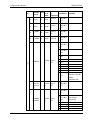
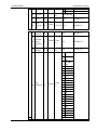
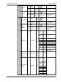
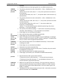
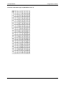
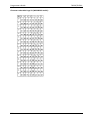
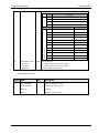
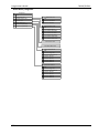
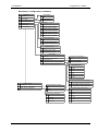
Command Overview ......................................................................................................................... 14
Commands sorted by function groups ......................................................................................... 17
Ignored Commands .......................................................................................................................... 22
Description of the Control Characters and Sequences: ................................................................... 23
Transmit Status Identification Table .............................................................................................. 196
Printer Parameter Table ................................................................................................................. 197
Character Sets and Fonts ....................................................................................................... 199
Representation of the printed data ............................................................................................... 199
Character Fonts .......................................................................................................................... 199
User defined character sets........................................................................................................ 200
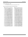
Character code tables ................................................................................................................. 201
Standard code pages - tables ......................................................................................................... 206
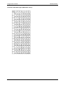
Character code table Page 0 (PC437: USA, Standard Europe): .................................................. 206
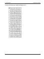
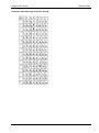
Character code table Page 1 (PC850: Multilingual Latin I): ........................................................ 207
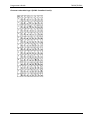
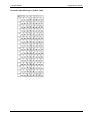
Character code table Page 2 (PC852: Latin II): ........................................................................... 208
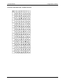
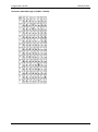
Character code table Page 3 (PC860: Portuguese): ................................................................... 209
Character code table Page 4 (PC863: Canadian French): ........................................................... 210
Character code table Page 5 (PC865: Nordic): ........................................................................... 211
Character code table Page 6 (PC858: Multilingual I + Euro): ..................................................... 212
Character code table Page 7 (PC866: Russian): .......................................................................... 213
Character code table Page 8 (WPC1252: Latin I):....................................................................... 214
Character code table Page 9 (PC862: Hebrew): ......................................................................... 215
Character code table Page 10 (PC737: Greek): .......................................................................... 216
Character code table Page 11 (PC874: Thai): ............................................................................. 217
Character code table Page 12 (PC857: Turkish): ........................................................................ 218
Character code table Page 16 (WPC1254: Turkish):................................................................... 219
Character code table Page 17 (WPC1250: Central Europe): ...................................................... 220
Character code table Page 18 (WPC28591: Latin 1): ................................................................. 221
Character code table Page 19 (WPC28592: Latin 2): ................................................................. 222
Character code table Page 20 (WPC28599: Turkish):................................................................. 223
Character code table Page 21 (WPC28605: Latin 9): ................................................................. 224
Character code table Page 22 (PC864: Arabic): .......................................................................... 225
Character code table Page 23 (PC720: Arabic): .......................................................................... 226
Character code table Page 24 (WPC1256: Arabic): .................................................................... 227
Character code table Page 25 (WPC28596: Arabic): .................................................................. 228
Character code table Page 26 (KATAKANA: Asia):...................................................................... 229
Character code table Page 27 (PC775: Baltic): ........................................................................... 230
Character code table Page 28 (WPC1257: Baltic): ..................................................................... 231
Character code table Page 29 (WPC28594: Baltic): ................................................................... 232
Asia Code Pages – Definition for USB Loader ............................................................................. 233
USB Interface ........................................................................................................................ 235
USB Descriptors .............................................................................................................................. 235
Device Descriptor ....................................................................................................................... 235
Configuration Descriptor ............................................................................................................ 236
Interface Descriptors .................................................................................................................. 237
Endpoint Descriptors .................................................................................................................. 238
String Descriptors ....................................................................................................................... 240
Printer Interface ............................................................................................................................. 242
IEEE 1284 Device ID (GET_DEVICE_ID) ....................................................................................... 242
SOFT_RESET ................................................................................................................................ 242
USB Reset ....................................................................................................................................... 242
USB Detach/Attach ......................................................................................................................... 242
Receipt Buffer ................................................................................................................................. 242
RS232 Interface..................................................................................................................... 243
Specifications.................................................................................................................................. 243
Handshake control ......................................................................................................................... 243
Receipt Buffer ................................................................................................................................. 244
Ethernet Interface................................................................................................................. 245
Overview 245
Features 245
Handshake control ......................................................................................................................... 245
Receipt Buffer ................................................................................................................................. 245
Service Menu ........................................................................................................................ 246
Menu handling ............................................................................................................................... 246
Selecting the service menu......................................................................................................... 246
Controlling the service menu ..................................................................................................... 247
Save changed settings ................................................................................................................ 248
LED Service Menu ........................................................................................................................... 248
Reset Printer ............................................................................................................................... 248
Run sensor test ........................................................................................................................... 248
Set EEPROM to default ............................................................................................................... 248
Print Service Menu ......................................................................................................................... 249
Exit .............................................................................................................................................. 256
Print Selftest ............................................................................................................................... 256
Diagnostic - Menu....................................................................................................................... 256
Configuration - Menu ................................................................................................................. 258
Information - Menu .................................................................................................................... 265
MF Menu .................................................................................................................................... 265
TH230 Diagnostic Functions .................................................................................................. 266
Selftest Printout .......................................................................................................................... 267
Sensor Test ................................................................................................................................. 273
EEPROM default settings ............................................................................................................ 273
Endurance test ............................................................................................................................ 275
Black Mark test ........................................................................................................................... 277
Description of EERPOM Updates.................................................................................................... 278
Specialties ................................................................................................................................... 278
Calculating Power On Time ........................................................................................................ 279
Technical Specifications ................................................................................................................. 280
ERROR Blink Pattern ....................................................................................................................... 285
Recoverable Errors ..................................................................................................................... 285
Automatic Recoverable Errors.................................................................................................... 285
Unrecoverable Errors.................................................................................................................. 285
Power-Up-Test Errors ................................................................................................................. 286
TH230/TH230+
Programmers Guide
Overview
Purpose of this document
This Programmers Guide describes the properties of the controller for the high speed ESCPOS thermal printer TH230/TH230+.
Introduction
The TH230 and the TH230+ are powerful and low cost thermal printers for all kind of POS
systems.
In this manual both printers will be referred to as TH230. Only in case of essential
differences there will be a distinction between TH230 and TH230+.
1
Programmers Guide
TH230/TH230+
General Characteristics of the Printer
•
High speed ESC-POS thermal printer
•
Interface Board Changeable
•
Different Host Interfaces: RS232, USB, PoweredUSB and others
•
Printer is able to operate in horizontal and vertical position
•
Paper width: 80 mm or 57.5 mm
•
Diameter of Paper rolls: up to 90 mm
•
High Print speed: up to 220 mm/s (110 mm/s with two color paper)
•
Thermal print line: 80mm width, 640 Dots, 203 dpi (0.125 mm) resolution
•
Print width 72 mm centered on 80 mm paper width
•
Different Codepages and loadable Character Sets
•
Bar Code printing
•
Paper feed with Stepper motor, vertical resolution: 203 dpi (0.125 mm)
•
Fast Cutter with Stepper motor and Home Sensor (cutting time is 300 ms)
•
Automatic Reverse Feeding after Cut to reduce Top Margin to 5 mm.
Sensors for Cover Open, Paper Near End, Paper End
2
•
Optional Mark Sensor usable for 80 mm paper on different positions
•
Parameter setting with configuration menu
•
Self test and Statistic Functions
•
Adjustable Power Consumption from 48 W to 110 W
•
Automatic Power Detection for Wincor-Nixdorf Power Supplies
TH230/TH230+
Programmers Guide
Firmware Characteristics of the Controller
The TH230 printer is controlled with the aid of control sequences, i.e. a series of
characters. The standard setting is thus overridden, which means that you are able to set
many print functions individually if the standard values do not correspond to your
requirements. Possible changes are, among others, the selection of different line feed
sizes and the printing of various graphics. You will see that it is very simple to control the
printer according to your own personal requirements. However, a precondition for proper
use is the correct installation and/or configuration of the system. In addition, you should
be familiar with the operating system of your computer.
With the interfaces USB 1.1 (USB 2.0 compliant) or RS232, all the status information’s can
be called up using the different control commands. Via this interface, it is possible to
synchronize the user software and the printing properties. The TH230 printer supports an
ESC POSTM command set.
Line feed
The line feeds of the TH230 printer are initiated by the control commands LF and ESC d.
The line spacing between 2 lines can be set by the control command ESC 3. The default
value after reset or power on is 3.37 mm, which equals 27 micro steps. One micro step
equals one dot distance of 1/203”.
3
Programmers Guide
TH230/TH230+
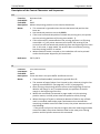
Offline State
If the TH230 printer leaving the online state, nevertheless it responds to all real time
commands and real time status commands. Sending other data than real time commands
may lead to data loss (see memory switch 2-8 Listen to Real-Time-Commands).
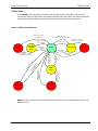
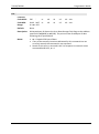
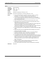
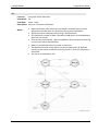
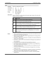
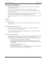
Online / Offline State Diagram
Voltage comes back
to normal value
Paper near end +
Print stop at paper near end enabled
Character >= Space,
Linefeed or Cut received
Voltage comes back
to normal value
Automatic
recoverable
error
Offline
Paper End
Offline
Real time request to
printer (DLE ENQ n)
User inserts
new paper
User inserts
new paper
Cutter
Error
printer (DLE ENQ n)
Sw
i
tch
off
/on
the
Un
pr
r
int
(T eco
er
he ve
rm ra
ist ble
or
Er
Er ro
ro r
r)
Real time request to
Character >= Space,
Linefeed or Cut received
Online
Recoverable
Error
Low / High
Voltage
Error
Character >= Space,
Linefeed or Cut received
Offline
Paper end
Offline
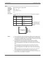
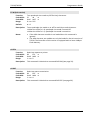
Remark: If the printer enters Offline State the Busy bit is set (see commands DLE EOT, GS
ENQ and GS a).
4
TH230/TH230+
Programmers Guide
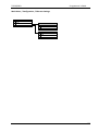
Operator Panel
The Operator Panel consists of one button and three LED’s. In addition there is one power
button to switch the printer on and off. In the following description, you can see which
function of the printer influence the LED’s and which functions are executed with the
buttons:
Linefeed Button
If you push this button once and release it, the printer executes a small paper feed. If you
push this button and hold it down, the printer feeds the paper as long as the button isn’t
released.
This button is also used in the self-test printing see chapter Print Service Menu on page
246.
Power LED Green
Off:
On:
Blinking:
Power is not stable.
Power is stable.
The maximum power setting is auto and no Wincor Nixdorf power supply is
used. The maximum power setting can be changed by the command GS ( E
fn=5 (see page 105). The user has to set a fix maximum power setting
according to the used power supply.
This LED is also used in the Diagnostic mode (see page 246).
Paper End LED Yellow
Off:
On:
Paper is loaded (Normal condition).
Printer detects paper roll end or paper roll near end.
This LED is also used in the Diagnostic mode (see page 246).
Error LED Red
Off:
On:
Blinking:
Normal Condition.
Offline.
Error.
This LED is also used in the Diagnostic mode. For an exact description of this LED see page
246 and page 287.
5
Programmers Guide
TH230/TH230+
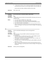
Sleep Mode
The Sleep Mode is used to save energy when the printer is switched on but has nothing to
print. This mode reduces the Total Cost of Ownership (TCO). Sleep Mode is switched on by
a Memory Switch. The Sleep Mode Waiting Time is set by a Customized Setting Value and
defines the time; the printer has to wait before it changes into Sleep Mode.
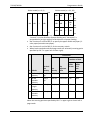
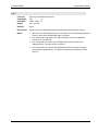
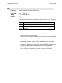
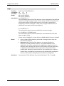
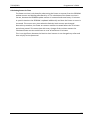
In the following state diagram the coherence between the different modes is described.
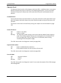
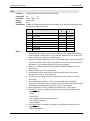
State Diagram of Sleep-Mode
Power button
pressed
(short-time)
Print data received or
Linefeed button pressed or
Power button pressed (short-time) or
Cover closed or
Data for Customer Display or
Command for Cash Drawer
(ASB Sleep off)
Printing
Mode
Print data
received or
Linefeed
button
pressed
Printing or
Linefeed
stops
Ready Mode
Off Mode
(X - 5)* seconds
after Ready or
Command ESC w n c
(ASB IDLE ON)
Power button
pressed for more
than 3 seconds
Sleep Mode 1
5 seconds after
entering from
Ready Mode
or last
command
finished
Status
command
received or
Cover open
Sleep Mode 0
* X is controlled by Customized Setting Values GS ( E - Function 5 - "Sleep Mode Waiting Time"
In previous models and firmware versions Sleep was called Idle and Ready was called
Standby. The terms are changed because of adaption on ENERGY STAR® nomenclature.
The current consumptions depend on different modes and the installed interface. Find
details in chapter “Technical Specifications”, page 282.
6
TH230/TH230+
Programmers Guide
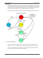
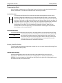
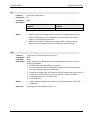
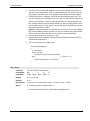
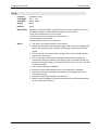
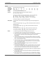
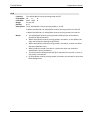
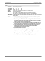
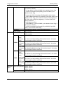
Diagram of Power States TH230 / TH230+
The following diagram is valid for TH230 and TH230+ and not for iPRINT.
There are different ways, to switch the Printer ON or OFF:
24V = ON
and Power Button is enabled
and Printer was ON before
24V = OFF
and Printer = OFF
24V = ON
and Power Button
is disabled
24V = ON
and Power Button is enabled
and Printer was OFF before
24V = ON
and Printer = OFF
24V = ON
and Power Button is enabled
and press Power Button
24V = OFF
24V = ON
and hit Power Button for 3 seconds
and (Power Button is enabled
or unrecoverable error
or undefined firmware)
24V = ON
and Printer = ON
24V = ON
and DLE SO
and DLE SO is enabled
24V = ON
and Printer = OFF
24V = ON
and press Power Button
and Power Button is enabled
24V = ON
and press Power Button
and Power Button is disabled
Fig.: Power ON and Power OFF
You will find additional information about “Power off control by host” on page 9.
7
Programmers Guide
TH230/TH230+
Programming Hints
In this chapter programmers may find some hints and tricks to make the thermal printout
faster, look better or increase the lifetime of the thermal print head.
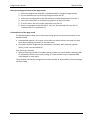
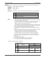
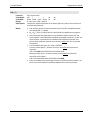
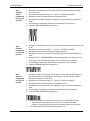
Vertical Dot Lines
Text
To increase the lifetime of the thermal print head the programmer has to avoid
printing of long vertical dot lines like in the ticket on the left side. In this ticket the
two vertical dot lines are printed always with the same two print dots of the thermal
print line. This leads to a big mechanical wear and thermal wear for this two dots. To
avoid early failure of the dots, vertical lines can be printed as dotted lines instead of
solid lines. Another possibility is to move the printout from ticket to ticket
horizontally by one dot. This can be done for example 10 times. After this the
printout starts from the beginning. Thus the lifetime is much higher compared to
print always on the same position.
Horizontal Dot Lines
To increase the performance of the printer the programmer has to avoid printing of long
horizontal dot lines like in the ticket on the left side. If the printer has
to print such lines the current to heat the print line is very high. For
Text
this reason the printer moves the paper slower and the performance
was decreased. To avoid bad performance, horizontal lines can be
printed as dotted lines instead of solid lines.
Reverse Feed after Cutting
To avoid paper bending the programmer should not use cuts with backward feeding of the
paper (command GS V(m=67).
Small Graphics Printing
If the printed graphics does not reach until the right border of the print area, the
programmer should transmit only this part of the graphics in which printed dots are
available. It is not necessary to transmit the null byte on the right side of the graphics and
this leads to a bad print performance.
8
TH230/TH230+
Programmers Guide
Power off control by the host
The following is an example of the printer power off process when the printer is turned off
using DLE SO (fn = 2) command.
1) Transmits the following continuous procedure before the system is turned off.
- Execute the last print command such as LF, ESC d, etc.
- Execute GS (D pL pH m a b (pL=3, m = pH =0, m =20, a =2, b =1)
- Execute GS r n (n =1)
2) Waits for the paper sensor status from the printer by the GS r n command.
3) Transmits DLE SO n a b (n =2, a =1, b =8)
4) Waits for the power off status
• The power off status is transmitted by the power-off sequence within 10 seconds after
transmitting DLE SO n a b.
• If the power off status is not checked, waits for 10 seconds or more after transmitting
DLE SO (fn = 2).
• For the serial interface model, the printer status is transmitted regardless of the
condition of the host.
The behavior of the Power Button is described on page 7.
Page Mode Tips
The thermal printer TH230 supports two different print modes: standard mode and page
mode. The standard mode is supported by all banking printers and in this mode, the
printers print data in the print buffer by executing the print commands (such as LF, CR, and
ESC J) or when the buffer is full. The standard mode is the print mode which prints data
one line at a time.
The page mode executes batch printing with FF
or ESC FF for all data in the print buffer stored after the page mode is selected with ESC L.
In this mode, the print commands other than FF or ESC FF, such as LF, CR, or ESC J, only
move the printing position and do not execute actual printing. Executing ESC S or FF
returns to standard mode. The page mode is the print mode which prints data one page at
a time. The page mode print data can be deleted by CAN. There are generally four possible
print directions in page mode which can be adjusted by ESC T.
ESC L
Standard
mode
Page mode
ESC S, FF
9
Programmers Guide
TH230/TH230+
Basic processing procedure for the page mode:
1.
2.
3.
4.
5.
6.
Select the page mode with ESC L (standard mode is changed to page mode).
Set the position and size for the printing area with ESC W.
Select the starting position and the direction for data development with ESC T.
Store print data (such as characters or graphics) in the print buffer.
Print all data in the print buffer collectively with ESC FF.
Return to standard mode with ESC S. (You can skip procedure 6 if you use FF
instead of ESC FF in procedure 5.)
Characteristics of the page mode
The flexible layout enables you to execute printing which you cannot accomplish in the
standard mode.
•
Downloaded graphics, bit images or bar codes can be printed on the same line with
other data including characters at the same time.
•
Characters and bit images can be rotated (90° clockwise, 180° clockwise (upside
down), or 90° counterclockwise).
Copy printing is possible.
•
Because printing with ESC FF enables storing of data in the print buffer, executing ESC
FF repeatedly results in the same printing. It is also possible to print repeated data
with changes in some parts.
The printable area can be changed several times by ESC W. Nevertheless, the whole page
will be printed.
10
TH230/TH230+
Programmers Guide
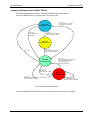
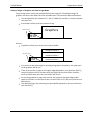
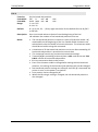
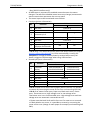
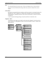
Absolute Origin of Graphics and Text in Page Mode
The printing area is set by the command ESC W (see page 63). The absolute origin of
graphics and text is the lower left of the printable area. This caused a different behavior:
Text and graphics (for example GS *, ESC (+*.BMP file) and GS ( L) can be printed in
the same row
Print buffer will be print form bottom to top.
Absolute origin
Graphics
TEXT
Caution:
A graphics will be print with a count of print buffer
Graphics buffer 3
Absolute origin
TEXT
Graphics buffer 2
Graphics buffer 1
If no space to the upper edge for printing the graphics completely, the upper part
of the graphics will be cut.
If the print position in page on the upper edge (depend on print direction (ESC T)),
the print position will be set down with the height of the print buffer. Graphics
which are built with more than one buffer will be cut.
For printing graphics in page, take care for the space to the upper edge and to
upper print lines! If is the space to low, set with GS $ or GS \ the print position to a
better point.
The absolute origin for positioning the print buffer depends on the print direction
(set with ESC T).
11
Programmers Guide
TH230/TH230+
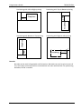
Positioning with Left to Right printing
Positioning with Top to Bottom printing
x
Graphics
TEXT
y
TEXT
y
x
Graphics
Positioning with Right to Left printing
Graphics
Positioning with Bottom to Top printing
TEXT
TEXT
Graphics
x
y
y
x
Barcode
Barcode can be used in Pagemode with limitations. Barcodes can only be print at start of
line, that’s why horizontal position commands do not work with barcode. For positioning
barcodes, ESC W is useable.
12
TH230/TH230+
Programmers Guide
Control Sequences
Control Characters and Control Sequences
The valid control characters are located in the code area below 20H. These are the
characters LF, FF, GS, DLE and ESC. All other control characters are not valid, and are
ignored by the controller.
The valid control characters (with the exception of ESC, GS and DLE) are single character
control commands, and directly start control functions.
ESC, GS and DLE are always the start of a multi-character control command, which consists
of a different number of characters after ESC, GS and DLE. They only perform the
requested command if the complete character string is valid. The whole control string will
be ignored if a wrong (not valid) character is found in the string. The next character is than
interpreted as the start of a new command.
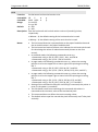
Notation of the Command Description
XXXX
Command Character or Command Sequence
Function:
Code:
Range:
Description:
Notes:
Name of the command
Code Sequence (Notation)
Hexadecimal = 0x..
Decimal
= ..
Binary = <……..>B
ASCII = “…”
Repeat bracket contents
= [ ] k Format
Describes the permitted range of values.
Describes the function of the command.
Provides important information on settings.
Default:
Describes the standard values.
Example:
Examples of the command in use.
Reference:
Reference to other commands.
13
Programmers Guide
TH230/TH230+
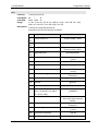
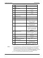
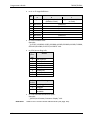
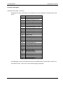
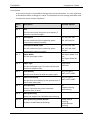
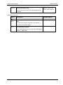
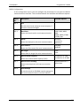
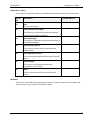
Command Overview
Code
HT
LF
FF
FF
CR
DLE
DLE EOT
DLE ENQ
DLE SO (fn = 2)
DC1
DC2
DC3
DC4
NAK
SYN
ETB
CAN
EM
SUB
ESC (+*.BMP file)
ESC BEL
ESC FF
ESC DC2
ESC DC4
ESC SYN
ESC SP
ESC !
ESC $
ESC %
ESC &
ESC ‘
ESC *
ESC * 1
ESC * b m
ESC ESC .
ESC 2
ESC 3
ESC 4
ESC :
ESC =
14
Function
Horizontal tab
Print and line feed
(1) Print and return to standard mode (in page mode)
(2) Print and feed marked paper to print starting position
Print and carriage return
Clear printer
Real time status transmission
Real time request to printer
Turn off the power
Print raster monochrome graphics
Select Double-Wide Characters
Select Single-Wide Characters
Feed n Print Lines
Feed n Dot Rows
Add n Extra Dot Rows
Print
Cancel print data in page mode
Full cut
Partial cut
Download BMP logo
Generate tone
Print data in page mode
Select 90 Degree Counter-Clockwise Rotated Print
Set Column
Select Pitch (Column Width)
Set right-side character spacing
Select print mode(s)
Set absolute print position
Select/cancel user-defined character set
Define user-defined characters
Write to User Data Storage
Select bit-image mode
Select bit-image mode - Line Graphics
Turn on/off TIFF compression
Turn underline mode on/off
Print Advanced Raster Graphics
Set line spacing to 1/6 inch
Set line spacing
Read from User Data Storage
Copy Character Set from ROM to RAM
Select peripheral device
Page
23
23
24
24
25
25
26
29
30
31
31
32
32
32
33
33
34
34
34
35
36
36
36
37
37
38
39
40
41
41
43
44
46
47
48
49
49
50
51
51
52
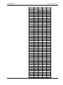
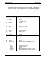
TH230/TH230+
ESC ?
ESC @
ESC D
ESC E
ESC G
ESC I
ESC J
ESC K
ESC L
ESC R
ESC S
ESC T
ESC V
ESC W
ESC Y
ESC [ ! t
ESC \
ESC a
ESC c 3
ESC c 4
ESC c 5
ESC d
ESC i
ESC j
ESC l
ESC m
ESC p
ESC r
ESC s
ESC t
ESC u
ESC v
ESC w n 7
ESC w n 8
ESC w n b
ESC w n c
ESC {
FS ! (Asia version)
FS & (Asia version)
FS - (Asia version)
FS . (Asia version)
FS 2 (Asia version)
FS C (Asia version)
FS S (Asia version)
Programmers Guide
Cancel user-defined characters
Initialize printer
Set horizontal tab positions
Turn emphasized mode on/off
Turn double-strike mode on/off
Turn italic print mode on/off
Print and feed paper
Select Single-Density Graphics
Select page mode
Select an international character set
Select standard mode
Select print direction in page mode
Turn 90° clockwise rotation mode on/off
Set printing area in page mode
Select Double-Density Graphics
Set control point
Set relative print position
Select justification
Select paper sensor(s) to output paper-end signals
Select paper sensor(s) to stop printing
Enable/disable feed button
Print and feed n lines
Full cut
Read from Non-Volatile Memory
Start firmware upgrade mode
Partial cut
Generate pulse
Set current color
Write to Non-Volatile Memory (NVRAM)
Select character code table
Transmit Peripheral Device Status
Transmit paper sensor status
Receipt shooting flush
Play melody from flash
Special Wincor barcode parameter
Switch the printer into Sleep-Mode.
Turn upside-down printing mode on/off
Select print mode(s) for Kanji characters
Select Kanji character mode
Turn underline mode on/off for Kanji characters
Cancel Kanji character mode
Define user-defined Kanji characters
Select Kanji character code system
Set Kanji character spacing
53
54
55
56
56
57
57
58
59
59
60
61
62
63
64
65
66
67
67
68
69
70
70
71
71
71
72
73
73
74
75
76
77
77
78
78
79
81
81
82
82
83
84
84
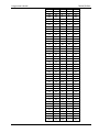
15
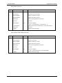
Programmers Guide
FS W (Asia version)
GS ETX
GS EOT
GS ENQ
GS !
GS “
GS “ U
GS #
GS $
GS ( A
GS ( D
GS ( E
Function 1
Function 2
Function 3
Function 4
Function 5
Function 6
Function 11
Function 12
Function 129
Function 130
Function 131
Function 132
GS ( FGS ( FGS (
FGS ( FGS ( F
GS ( L
Function 48
Function 51
Function 64
Function 65
Function 66
Function 67
Function 69
GS *
GS /
GS :
GS @
GS B
GS H
GS I
GS L
GS P
GS V
GS W
GS \
GS ^
16
TH230/TH230+
Turn quadruple-size mode on/off for Kanji characters
Real time request to printer
Real time status transmission
Real time printer status transmission
Select character size
Select memory type (SRAM/Flash)
Flash Memory User Sectors Allocation
Select the Current Logo
Set absolute vertical print position in page mode
Executes test and diagnosis functions
Enable/disable real-time command
Customize NV memory
Changes into the user setting mode.
Ends user setting mode session. (Performs a software reset.)
Changes the memory switch.
Transmits the host the value for the memory switch.
Changes the customized setting values.
Transmits the customized setting values.
Sets communication condition of serial interface.
Transmits communication condition of serial interface.
Set serial number
Set production date
Sets communication condition of Ethernet interface.
Transmits communication condition of Ethernet interface.
Set adjustment value(s)
85
85
85
86
87
88
89
90
91
92
93
94
96
97
98
101
102
109
114
116
117
117
118
119
120
Specify graphics data
Sends the entire capacity of NV graphics domains.
Sends the available capacity of NV graphics memory.
Sends the key code list for defined NV graphics.
Performs batch deletion of all NV graphics data.
Deletes the specified NV graphics data.
Defines (in raster format) NV graphics data.
Prints the specified NV graphics.
Define downloaded bit image
Print downloaded bit image
Start/end macro definition
Erase User Flash Sector
Turn white/black reverse printing mode on/off
Select printing position of HRI characters
Transmit printer ID
Set left margin
Set horizontal and vertical motion units
Select cut mode and cut paper
Set printing area width
Set relative vertical print position in page mode
Execute macro
122
126
127
129
130
131
132
134
142
143
145
146
147
148
149
153
154
155
157
158
159
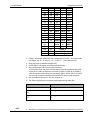
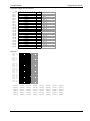
TH230/TH230+
GS a
GS b
GS f
GS g 0
GS g 2
GS h
GS k
GS p
GS r
GS w
GS 0x81
GS 0x82
GS 0x83
GS 0x84
GS 0x8D
GS 0x8E
GS 0x8F
GS 0xA0
GS 0xFF
US EOT
US ENQ
US t
US V
US z
Programmers Guide
Enable/disable Automatic Status Back (ASB)
Turn smoothing mode on/off
Select font for HRI characters
Initialize maintenance counter
Transmit maintenance counter
Set bar code height
Print bar code
Select PDF 417 parameters
Transmit status
Set bar code width
Set paper type
Print raster monochrome graphics
Print raster color graphics
Download logo image
Text strike-through mode
Download paper type description
Return paper type description
Set temporary max target speed
Reset firmware
Convert 6-dots/mm bitmap to 8-dots/mm bitmap
Select superscript or subscript modes
Print Test Form
Send printer software version
Real time commands disabled
160
163
163
164
166
168
169
183
185
187
188
189
189
190
191
192
193
193
194
194
194
195
195
195
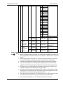
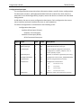
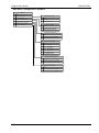
Commands sorted by function groups
Print commands
LF
FF
FF
CR
NAK
SYN
ESC FF
ESC J
ESC d
Print and line feed
(1) Print and return to standard mode (in page mode)
(2) Print and feed marked paper to print starting position
Print and carriage return
Feed n Dot Rows
Add n Extra Dot Rows
Print data in page mode
Print and feed paper
Print and feed n lines
23
24
24
25
32
33
36
57
70
17
Programmers Guide
TH230/TH230+
Line spacing commands
ESC 2
ESC 3
Set line spacing to 1/6 inch
Set line spacing
49
50
Select Double-Wide Characters
Select Single-Wide Characters
Cancel print data in page mode
Select 90 Degree Counter-Clockwise Rotated Print
Set right-side character spacing
Select print mode(s)
Set absolute print position
Turn underline mode on/off
Cancel user-defined characters
Turn emphasized mode on/off
Turn italic print mode on/off
Turn double-strike mode on/off
Select an international character set
Turn 90° clockwise rotation mode on/off
Set current color
Select character code table
Turn upside-down printing mode on/off
Select character size
Turn white/black reverse printing mode on/off
Turn smoothing mode on/off
Text strike-through mode
Select superscript or subscript modes
31
32
34
36
38
39
40
48
53
56
57
56
59
62
73
74
79
87
147
163
191
194
Enable/disable feed button
69
Character commands
DC2
DC3
CAN
ESC DC2
ESC SP
ESC !
ESC $
ESC ESC ?
ESC E
ESC I
ESC G
ESC R
ESC V
ESC r
ESC t
ESC {
GS !
GS B
GS b
GS 0x8D
US ENQ
Panel button commands
ESC c 5
Paper sensor commands
ESC c 3
Select paper sensor(s) to output paper-end signals
67
ESC c 4
Select paper sensor(s) to stop printing
68
Print position commands
HT
ESC DC4
ESC SYN
18
Horizontal tab
Set Column
Select Pitch (Column Width)
23
37
37
TH230/TH230+
ESC $
ESC D
ESC T
ESC W
ESC \
ESC a
GS $
GS L
GS W
GS \
Programmers Guide
Set absolute print position
Set horizontal tab positions
Select print direction in page mode
Set printing area in page mode
Set relative print position
Select justification
Set absolute vertical print position in page mode
Set left margin
Set printing area width
Set relative vertical print position in page mode
40
55
61
63
66
67
91
153
157
158
Bit-image commands (graphics)
DC1
ESC (+*.BMP file)
ESC *
ESC * 1
ESC * b m
ESC .
ESC K
ESC Y
GS ( L
Function 48
Function 51
Function 64
Function 65
Function 66
Function 67
Function 69
GS *
GS /
GS #
US EOT
GS 0x82
GS 0x83
GS 0x84
GS 0x81
Print raster monochrome graphics
Download BMP logo
Select bit-image mode
Select bit-image mode - Line Graphics
Turn on/off TIFF compression
Print Advanced Raster Graphics
Select Single-Density Graphics
Select Double-Density Graphics
Specify graphics data
Sends the entire capacity of NV graphics domains.
Sends the available capacity of NV graphics memory.
Sends the key code list for defined NV graphics.
Performs batch deletion of all NV graphics data.
Deletes the specified NV graphics data.
Defines (in raster format) NV graphics data.
Prints the specified NV graphics.
Define downloaded bit image
Print downloaded bit image
Select the Current Logo
Convert 6-dots/mm bitmap to 8-dots/mm bitmap
Print raster monochrome graphics
Print raster color graphics
Download logo image
Set paper type
31
35
44
46
47
49
58
64
122
126
127
129
130
131
132
134
142
143
90
194
189
189
190
188
Real time status transmission
Set control point
Transmit Peripheral Device Status
Transmit paper sensor status
Transmit printer ID
26
65
75
76
149
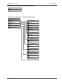
Status commands
DLE EOT
ESC [ ! t
ESC u
ESC v
GS I
19
Programmers Guide
GS a
GS r
US V
TH230/TH230+
Enable/disable Automatic Status Back (ASB)
Transmit status
Send printer software version
160
185
195
Special Wincor barcode parameter
Set bar code height
Print bar code
Select PDF 417 parameters
Set bar code width
Select printing position of HRI characters
Select font for HRI characters
Set and print barcode (PDF417, QR)
78
168
169
183
187
148
163
135
Start/end macro definition
Execute macro
145
159
Bar code commands
ESC w n b
GS h
GS k
GS p
GS w
GS H
GS f
GS ( k
Macro function commands
GS :
GS ^
Mechanism control commands (cut, cash drawer, tone)
ESC BEL
ESC i
ESC m
ESC p
ETB
EM
SUB
ESC w n 8
GS V
GS 0xA0
Generate tone
Full cut
Partial cut
Generate pulse
Print
Full cut
Partial cut
Play melody from flash
Select cut mode and cut paper
Set temporary max target speed
36
70
71
72
33
34
34
77
155
193
Select print mode(s) for Kanji characters
Select Kanji character mode
Turn underline mode on/off for Kanji characters
Cancel Kanji character mode
Define user-defined Kanji characters
Select Kanji character code system
Set Kanji character spacing
Turn quadruple-size mode on/off for Kanji characters
81
81
82
82
83
84
84
85
Kanji commands
FS ! (Asia version)
FS & (Asia version)
FS - (Asia version)
FS . (Asia version)
FS 2 (Asia version)
FS C (Asia version)
FS S (Asia version)
FS W (Asia
version)
20
TH230/TH230+
Programmers Guide
Customize commands
ESC ‘
ESC 4
ESC :
ESC j
ESC s
GS ( E
GS “
GS “ U
Function 1
Function 2
Function 3
Function 4
Function 5
Function 6
Function 11
Function 12
Function 129
Function 130
Function 131
Function 132
GS ( F
GS @
GS 0x8E
GS 0x8F
Write to User Data Storage
Read from User Data Storage
Copy Character Set from ROM to RAM
Read from Non-Volatile Memory
Write to Non-Volatile Memory (NVRAM)
Customize NV memory
Select memory type (SRAM/Flash)
Flash Memory User Sectors Allocation
Changes into the user setting mode.
Ends user setting mode session. (Performs a software reset.)
Changes the memory switch.
Transmits the host the value for the memory switch.
Changes the customized setting values.
Transmits the customized setting values.
Sets communication condition of serial interface.
Transmits communication condition of serial interface.
Set serial number
Set production date
Sets communication condition of Ethernet interface.
Transmits communication condition of Ethernet interface.
Set adjustment value(s)
Erase User Flash Sector
Download paper type description
Return paper type description
43
51
51
71
73
94
88
89
96
97
98
101
102
109
114
116
117
117
118
119
120
146
192
193
Select peripheral device
Initialize printer
Start firmware upgrade mode
Receipt shooting flush
Switch the printer into Sleep-Mode.
Reset firmware
52
54
71
77
78
194
Cancel print data in page mode
Print data in page mode
Select page mode
Select standard mode
Select print direction in page mode
Set printing area in page mode
Set absolute vertical print position in page mode
Set relative vertical print position in page mode
34
36
59
60
61
63
91
158
Control commands
ESC =
ESC @
ESC l
ESC w n 7
ESC w n c
GS 0xFF
Pagemode
CAN
ESC FF
ESC L
ESC S
ESC T
ESC W
GS $
GS \
21
Programmers Guide
TH230/TH230+
Resolution
GS P
Set horizontal and vertical motion units
154
Clear printer
Real time status transmission
Real time request to printer
Turn off the power
Real time request to printer
Real time status transmission
Real time printer status transmission
Enable/disable real-time command
25
26
29
30
85
85
86
93
Initialize maintenance counter
Transmit maintenance counter
164
166
ESC %
ESC &
ESC ?
Select/cancel user-defined character set
Define user-defined characters
Cancel user-defined characters
41
41
53
GS ( A
US t
US z
Executes test and diagnosis functions
Print Test Form
Real time commands disabled
92
195
195
Real Time
DLE
DLE EOT
DLE ENQ
DLE SO (fn = 2)
GS ETX
GS EOT
GS ENQ
GS ( D
Statistics
GS g 0
GS g 2
User defined characters
Test
Ignored Commands
The following commands are ignored:
DLE; ESC c 0; ESC c 1; ESC c 3; ESC c 6; ESC j; ESC s
22
TH230/TH230+
Programmers Guide
Description of the Control Characters and Sequences:
HT
Function:
Code ASCII:
Code HEX:
Description:
Horizontal tab
HT
0x09
Moves the printing position to the next horizontal tab.
Notes:
• This command is ignored unless the next horizontal tab position has
been set.
• Horizontal tab positions are set by ESC D.
• If the next horizontal tab position exceeds the printing area, the printer
sets the printing position to [Printing area width + 1].
• If this command is processed when the printing position is at [Printing
area width + 1], the printer executes print buffer-full printing of the
current line and horizontal tab processing from the beginning of the next
line. In this case, in page mode, the printer does not execute printing,
but the printing position is moved.
• When underline mode is turned on, the underline will not be printed
under the tab space skipped by this command.
Reference:
ESC D, ESC 3
Function:
Code ASCII:
Code HEX:
Description:
Print and line feed
LF
0x0A
Prints the data in the print buffer and feeds one line.
Notes:
• If auto linefeed enabled, command is ignored after CR.
• The amount of paper fed per line is based on the value set using the line
spacing command ESC 2 (see page 49), or ESC 3 (see page 50).
• After printing, the printing position moves to the beginning of the line.
When a left margin is set in standard mode, the position of the left
margin is the beginning of the line.
• When this command is processed in page mode, only the printing
position moves, and the printer does not perform actual printing.
• When the origin of layout is selected to bottom of label or top of black
mark in standard mode and a paper feed amount that exceeds the
remaining printable area of the label is sent, the printer executes one of
the following:
- If the printer will print a line that is higher than the remaining printable
area of the label, the printer feeds the label to the next print starting
position and the printer executes this command.
LF
23
Programmers Guide
TH230/TH230+
• - If the printer will print in the remaining printable area of the label, but
the feed amount exceeds the remaining printable area of the label, the
printer prints the label and feeds to bottom of the label.
Reference:
ESC 2, ESC 3, ETB
Function:
Code ASCII:
Code HEX:
Description:
(1) Print and return to standard mode (in page mode)
FF
0x0C
In page mode, prints the data in the print buffer collectively and returns to
standard mode.
• This command is enabled only in page mode.
• The data is deleted in the printing area after being printed.
• This command returns the values set by ESC W to the default values.
• The value set by ESC T is maintained.
• After printing, the printing position moves to the beginning of the line.
When a left margin is set, the position of the left margin is the beginning
of the line.
FF
Notes:
FF
Function:
Code ASCII:
Code HEX:
Description:
Notes:
Reference:
24
(2) Print and feed marked paper to print starting position
FF
0x0C
Prints the data in the print buffer and feeds marked paper to the print
starting position.
• If the BM sensor is enabled by using memory switch 0x80 the printer
feeds the marked paper to the next mark position.
• If the paper is at the print starting position and there is no data in the
print buffer, this command is ignored.
• If the BM sensor is enabled by using memory switch 0x80 the minimum
foot loss is > 5 mm.
• After printing, the printing position moves to the beginning of the line.
When a left margin is set, the position of the left margin is the beginning
of the line.
Memory switch (see page 98)
TH230/TH230+
Programmers Guide
CR
Function:
Print and carriage return
Code ASCII: CR
Code HEX: 0x0D
Description:
When automatic line feed is
When automatic line feed is
enabled
disabled
Executes printing one line feed as LF This command is ignored
Notes:
• After printing, the printing position moves to the beginning of the line.
When a left margin is set in standard mode, the position of the left
margin is the beginning of the line.
• When this command is processed in page mode, only the printing
position moves and the printer do not perform actual printing.
Function:
Code ASCII:
Code HEX:
Description:
Clear printer (This command is ignored)
DLE
0x10
Clears the print line buffer without printing and sets the printer to the
following condition:
• Double-wide command (0x12) is canceled
• Line spacing, pitch and user-defined character sets are maintained at
current selections (RAM is not affected)
• Single-wide, single-high, non-rotated, and left-aligned characters are set
• Printer is restarted and error status is cleared in a fault condition
• Printing position is set to column one
• Knife is homed
Notes:
• A DLE command followed by a 04 or 05 is interpreted as a “Real Time
Command”.
Reference:
DLE ENQ, DLE EOT and DLE SO (fn = 2)
DLE
25
Programmers Guide
TH230/TH230+
DLE EOT
Function:
Code ASCII:
Code HEX:
Range:
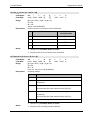
Real time status transmission
DLE EOT n
0x10 0x04 n
1≤n≤4
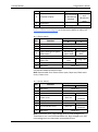
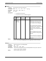
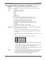
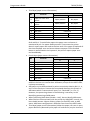
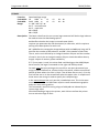
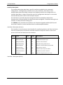
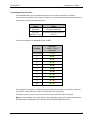
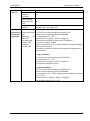
Description:
Transmits 1 byte of status data specified in real time, using n as follows:
n
1
2
3
4
Notes:
Function
Transmit printer status
Transmit busy status
Transmit error status
Transmit paper roll sensor status
• This is a real-time command that the printer executes upon receiving it.
Take the following into consideration:
- If this command interrupts the code string of another command, this
command is processed as a parameter of the other command;
therefore, the print result will not be correct.
- If a command such as bit-image or defined data has a code string that
is the same as a code string in a parameter, the printer processes and
then continues with the bit-image or other command.
• This command is executed even when the printer is offline or an error
occurs.
• If the receive buffer is full the execution depends from Memory Switch
2-8 (Listen to Real-Time-Commands - see command GS ( E).
- If Memory Switch 2-8 is set to off (48): command is executed.
- If Memory Switch 2-8 is set to on (49): command is not executed.
• This command can be used when the printer is disabled by ESC =.
• When transmitting block data (Header ~ NUL), the status will be sent
after that.
• Each status equals 1 byte.
• This command can be disabled by US z (page 195).
• This command is identical to command GS EOT.
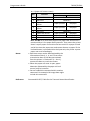
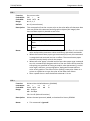
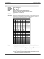
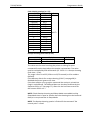
The status to be transmitted is as follows:
n = 1 (printer status)
26
Bit
Function
0
1
2
Not used
Not used
Drawer kick-out connector
pin 3
3
Busy
Value
0
1
Fixed to 0
Fixed to 1
Low
High
Not Busy
Busy
TH230/TH230+
Programmers Guide
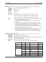
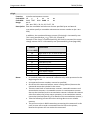
4
Not used
5
Customer display
Fixed to 1
Connected
Not connected
and
or Handshake
Handshake
blocked
ready
6 Undefined
7 Not used
Fixed to 0
Bit 3: Busy is set when the printer enters the Offline State (see chapter
Online / Offline State Diagram) or if the receive buffer is nearly full.
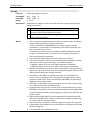
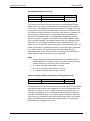
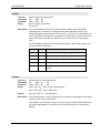
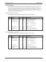
n = 2 (busy status)
Bit
Function
Value
0
1
0
1
2
Not used
Fixed to 0
Not used
Fixed to 1
Cover
Closed
Open
Paper feeding with paper
Not during During paper
3
feed button
paper feed
feed
4 Not used
Fixed to 1
Printing stop due to a
No paper end
5
Printing stops
paper end
stop
6 Recoverable Error
No error
Error occured
7 Not used
Fixed to 0
Bit 5: Bit 5 becomes “1” as sensor of the roll paper detects the paper
not present made to the print stop.
Bit 6: Recoverable Error means Cover open, Paper out, Black mark
error, Cutter error.
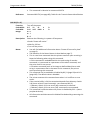
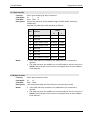
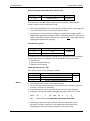
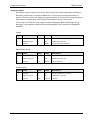
n = 3 (error status)
Bit
Function
0
1
2
Not used
Not used
Undefined
3
Cutter error
4
5
Not used
Undefined
6
Unrecoverable Error
7
Not used
Value
0
1
Fixed to 0
Fixed to 1
Error
occurred
Fixed to 1
No error
Error
occurred
Fixed to 0
No error
Bit 6: Thermistor error, High voltage error or Low voltage error.
Thermistor error is an unrecoverable error. High voltage error and
Low voltage error are automatic recoverable errors!
27
Programmers Guide
TH230/TH230+
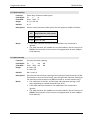
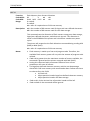
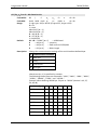
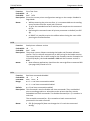
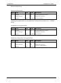
n = 4 (paper roll sensor status)
Bit
0
1
2
3
4
5
6
7
Notes:
Reference:
28
Function
Not used
Not used
Paper near end
sensor
Paper near end
sensor
Not used
Paper end sensor
Paper end sensor
Not used
Value
0
1
Fixed to 0
Fixed to 1
Paper present
No paper
Paper present
No paper
Fixed to 1
Paper present
No paper
Paper present
No paper
Fixed to 0
Bit 2 and Bit 3: To avoid false reports the paper near end sensor is
monitored by a 0.2 m paper feed hysteresis. That means the printer
doesn’t report paper near end to the host until 0.2 m paper is feed
and all the time the paper near end sensor detects no paper! If the
linefeed button is pressed within the hysteresis, the printer reports
paper near end immediately.
• Real time status can be differentiated by the
information of bits 0, 1, 4, and 7 from other
transmission data. If the data transmitted
from the printer is “0xx1xx10” (x = 0 or 1),
process the data as a real time status.
• When the paper roll cover is open, paper
detection (detected by the paper roll end
sensor) may be incorrect.
• Do not embed this command within another
command. For example: Bit image data might
include this command.
Command GS EOT; Table for the Transmit Status Identification
TH230/TH230+
Programmers Guide
DLE ENQ
Function:
Code ASCII:
Code HEX:
Range:
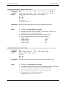
Real time request to printer
DLE ENQ n
0x10 0x05 n
1≤n≤2
Description:
Responds to a request in real time from the host system. n specifies the
request as follows:
n
1
2
Notes:
Request
Restarts printing from the beginning of the line where an error
occurred, after recovering from the error.
Recover from an error after clearing the data in the receive
buffer and print buffers.
• This is a real-time command that the printer executes upon receiving it.
Note the following when using this command.
• If this command is embedded within the code string of another
command, it is processed as a parameter of the other command, and
the print result is not correct.
• If another command (such as bit image or defined data) has a code
string in a parameter that is the same as this command, the printer
starts processing this command.
• This command is executed even when the printer is offline
• If the receive buffer is full the execution depends from Memory Switch
2-8 (Listen to Real-Time-Commands - see command GS ( E).
- If Memory Switch 2-8 is set to off (48): command is executed.
- If Memory Switch 2-8 is set to on (49): command is not executed.
• When a recoverable error occurs, after removing the cause of the error,
the printer can recover from the error by transmitting DLE ENQ 1 or DLE
ENQ 2 without the printer being turned off.
• DLE ENQ 1 or DLE ENQ 2 is enabled only when a recoverable error
occurs, with the exception of an automatically recovered error, and is
ignored in other cases. Errors recoverable by DLE ENQ 1 or DLE ENQ 2
depend on the printer model.
• DLE ENQ 1 or DLE ENQ 2 is also executed to recover from a recoverable
error when the printer is disabled by ESC =.
• In page mode, if the printer recovers from a recoverable error by using
DLE ENQ 2, the printer returns to standard mode after clearing the data
in receive and print buffers and changing the values set by ESC W to the
default values.
• After processing DLE ENQ 2, the printing position is moved to the left
side of the printable area. Printer is in the status “beginning of the line,”
or “there is data in the print buffer.”
• If the value of n is out of the specified range, this command is ignored.
• A description of the different errors and the error blink patterns can be
found on page 285.
• This command can be disabled by US z.
29
Programmers Guide
TH230/TH230+
• This command is identical to command GS ETX.
Reference:
Command GS ETX (see page 85); Table for the Transmit Status Identification
DLE SO (fn = 2)
Function:
Code ASCII:
Code HEX:
Range:
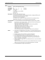
Turn off the power
DLE SO
fn
a
0x10 0x0E 0x02 a
fn = 2
a=1
b=8
Description:
Executes the following in a power-off sequence:
b
b
• Sends “Power off notice.”
• Wait for 250 ms.
• Turn off the printer
Notes:
30
• You will find additional information about “Power off control by host”
on page 9).
• The behavior of the Power Button is described on page 7).
• This is a real-time command that the printer executes upon receiving it.
Note the following when using this command.
• If this command is embedded within the code string of another
command, it is processed as a parameter of the other command, and
the print result is not correct.
• If another command (such as bit image or defined data) has a code
string in a parameter that is the same as this command, the printer
starts processing this command.
• This command can be enabled or disabled by GS ( D (page 93) and US z
(page 195). The default value is disabled.
• The printer executes this command even when it is in offline or error
status.
• If the receive buffer is full the execution depends from Memory Switch
2-8 (Listen to Real-Time-Commands - see command GS ( E).
- If Memory Switch 2-8 is set to off (48): command is executed.
- If Memory Switch 2-8 is set to on (49): command is not executed.
• This command is effective when the printer is disabled by ESC = (select
peripheral device).
• All information and data stored in RAM will be deleted by processing this
command.
TH230/TH230+
Programmers Guide
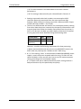
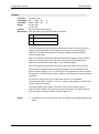
• When the power is turned off, the printer transmits [header + status +
NUL] to the host.
Power off notice
Hex
Decimal
Data
Header
0x3B
59
1 byte
Status
0x30
48
1 byte
NUL
0x00
0
1 byte
• The power-off notice can be differentiated from other transmission
data. When the data transmitted from the printer is
[Hex=0x3B/Decimal=59], the host should process 3 bytes of data up to
NUL as the notice from the printer. If the second byte is
[Hex=30H/Decimal=48], this is the power off notice. An exception is
described below:
• When the host is communicating with the printer by XON/XOFF
control, an XOFF code might interrupt [Header ~ NUL].
• In iPRINT this command leads to a virtual pressing of the power button.
Depending of the settings in the Operating System the behavior is
different (hibernation, power down, do nothing…). The TH230+ printer
part of the iPRINT system follows the achieved power state.
Reference:
Table for the Transmit Status Identification
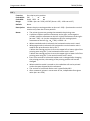
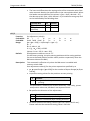
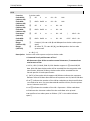
Function:
Code ASCII:
Print raster monochrome graphics
DC1 n1 … n72 (576 dots, 80 mm paper), or n51 (408 dots, 57.5 mm
paper)
0x11 n1 … n72 (576 dots for 80 mm paper), or n51 (408 dots for 57.5 mm
paper)
n1 to n72/n51 corresponds to one dot row data for a thermal receipt
printer
This command is identical to command GS 0x82.
DC1
Code HEX:
Range:
Description:
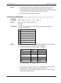
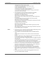
DC2
Function:
Code ASCII:
Code HEX:
Description:
Select Double-Wide Characters
DC2
0x12
Prints double-wide characters. The printer is reset to single-wide mode
after a
line has been printed or the Clear Printer (0x10) command is received.
Double-wide characters may be used in the same line with single-wide
characters.
Reference:
ESC ! (see page 39), GS !
31
Programmers Guide
TH230/TH230+
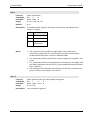
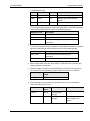
DC3
Function:
Code ASCII:
Code HEX:
Description:
Select Single-Wide Characters
DC3
0x13
Prints single-wide characters. Single-wide characters may be used in the
same line with double-wide characters.
Reference:
ESC ! (see page 39), GS !
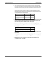
Function:
Code ASCII:
Code HEX:
Range:
Feed n Print Lines
DC4 n
0x14 n
0 ≤ n ≤ 255
Description:
Feeds the paper n lines at the current line height without printing.
Notes:
• This command is enabled only when processed at the beginning of the
line.
• New applications should use the command ESC d!
Function:
Code ASCII:
Code HEX:
Range:
Feed n Dot Rows
NAK n
0x15 n
0 ≤ n ≤ 255
Description:
Feeds the paper n dot rows (n/8 mm, n/203 inch), without printing.
Notes:
• Value of n: n/203 inch
• New applications should use the command ESC J.
DC4
NAK
32
TH230/TH230+
Programmers Guide
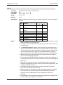
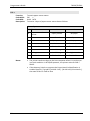
SYN
Function:
Code ASCII:
Code HEX:
Range:
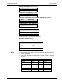
Add n Extra Dot Rows
SYN n
0x16 n
0 ≤ n ≤ 16
Default:
n = 3 extra dot rows
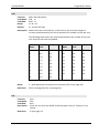
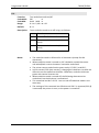
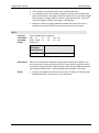
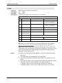
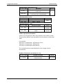
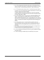
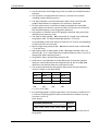
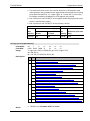
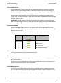
Description: Adds n extra dot rows (n/8 mm, n/203 inch) to the character height to
increase space between print lines or decrease the number of lines per inch.
The following table shows the relationship between the number of lines per
inch and each extra dot row added:
Extra
Rows
Lines Per
Inch
Dot Rows
Extra
Rows
Lines Per
Inch
Dot Rows
0
8.5
24
9
6.1
33
1
8.1
25
10
6.0
34
2
7.8
26
11
5.8
35
3
7.5
27
12
5.6
36
4
7.2
28
13
5.5
37
5
7.0
29
14
5.3
38
6
6.8
30
15
5.2
39
7
6.5
31
16
5.1
40
8
6.3
32
Notes:
• New applications should use the command ESC 3 (see page 50)!
Reference:
ESC 2 (see page 49), ESC 3 (see page 50)
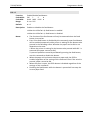
ETB
Function:
Code ASCII:
Code HEX:
Description:
Print
ETB
0x17
Prints one line from the buffer and feeds paper one line. Executes LF on
receipt.
Reference:
LF (see page 23)
33
Programmers Guide
TH230/TH230+
CAN
Function:
Code ASCII:
Code HEX:
Description:
Cancel print data in page mode
CAN
0x18
In page mode, deletes all the print data for the current printing area.
Notes:
• This command is enabled only in page mode
• If data set in the previously specified printing area is set in the currently
specified printing area, it is deleted.
Function:
Code ASCII:
Code HEX:
Description:
Full cut
EM
0x19
This command is the same like ESC i (see page 70).
Notes:
• WINCOR NIXDORF suggests using the newer command GS V (see page
155) to cut the receipt.
EM
• If not at beginning of line, a linefeed will be done
SUB
Function:
Code ASCII:
Code HEX:
Description:
Partial cut
SUB
0x1A
This command is the same like ESC m (see page 71).
Notes:
• WINCOR NIXDORF suggests using the newer command GS V (see page
155) to cut the receipt.
• If not at beginning of line, a linefeed will be done
34
TH230/TH230+
Programmers Guide
ESC (+*.BMP file)
Function:
Download BMP logo
Code ASCII:
Code HEX:
Range:
ESC (+*.BMP file)
0x1B (+*.BMP file)
Maximum width = 576
Maximum height = 512
Description:
Enters a downloaded BMP logo into RAM or flash.
The downloaded BMP logo can be printed by using the print downloaded
bit image (1D 2F m) command.
To downloaded BMP file to save it as a logo, send the hexadecimal code 1B
followed by the whole BMP file.
The printer decodes the BMP file header and will save the image data after
checking important parameters, such as:
- Width,
- Height,
- Number of colors (only monochrome images are accepted)
BMPs and bit images continue to be definable only for the receipt station.
However, there is no longer an automatic erasure whenever the user
downloads a character set (as happened previously) as well as in the case
where the current logo was never set > 0, (the automatic erasure if user
flash memory had filled up with inactive logo 0 definitions upon next power
cycle). Warnings about the effect of running out of defined logo space
during a download apply (i.e. the command is ignored). The application is
required to manage user data space, downloaded font space, and logo
space.
After downloading a logo to the printer, wait 100 ms to allow the printer
time to write the logo to flash.
Notes:
• Images widther than the maximum width will be cutted on the right side
• Images higher than the maximum width will be ignored.
• Exceptions: BMP file images that are not monochrome are put into the
print buffer.
• Related information: Microsoft BMP bitmap file format.
35
Programmers Guide
TH230/TH230+
ESC BEL
Function:
Generate tone
Code ASCII:
Code HEX:
Description:
ESC BEL
0x1B 0x07
Generates an audible tone. Performed by the printer to signal certain
conditions.
Notes:
• If you use ESC BEL after a print instruction, the printer generates the
audible tone not until print completion. Thus, the tone is synchronized
with printing.
Function:
Print data in page mode
Code ASCII:
Code HEX:
Range:
ESC FF
0x1B 0x0C
None
Description:
In page mode, prints all buffered data in the printable area collectively.
Notes:
• This command is enabled only in page mode.
• After printing, the printer does not clear the buffered data, the printing
position, or values set by other commands.
• The printer returns to standard mode with FF, ESC S, and ESC @. When it
returns to standard mode by ESC @, all settings are cancelled.
ESC FF
ESC DC2
Function:
Code ASCII:
Code HEX:
Description:
36
Select 90 Degree Counter-Clockwise Rotated Print
ESC DC2
0x1B 0x12
Rotates characters 90 degrees counter-clockwise. The command remains in
effect until the printer is reset or until a Init printer (0x1B 0x40) or Cancel
Rotated Print (0x1B 0x56) command is received.
TH230/TH230+
Programmers Guide
ESC DC4
Function:
Code ASCII:
Code HEX:
Range:
Set Column
ESC DC4 n
0x1B 0x14 n
1 ≤ n ≤ 45 (Standard pitch)
1 ≤ n ≤ 56 (Compressed pitch)
Default:
n=1
Description:
Prints the first character of the next print line in column n. This command
must be sent for each line not printed at column one. The value of n is set
to one after each line.
Notes:
• If the value of n is out of the specified range, the command is ignored
and the value of n is set to one.
• Double width: This command prints the first character of the print line
depending of the actual font. Therefore this command is not influenced
by the Double with command (ESC !) or the Select character size
command (GS !).
ESC SYN
Function:
Code ASCII:
Code HEX:
Range:
Select Pitch (Column Width)
ESC SYN n
0x1B 0x16 n
0≤n≤1
n = 0 (Standard pitch = Font A)
n = 1 (Compressed pitch = Font B)
Default:
n = 0 (Standard pitch)
Description:
The following table provides the print characteristics for both pitches on the
receipt station.
Notes:
Pitch
Dots
Columns
Columns
80 mm Paper 57.5 mm
Paper
CPI
Standard (Font A)
13 x
24
44
31
15.6
Compressed (Font
B)
10 x
24
57
40
20.3
• This command and the command ESC ! affect pitch selection.
37
Programmers Guide
TH230/TH230+
ESC SP
38
Function:
Code ASCII:
Code HEX:
Range:
Set right-side character spacing
ESC SP
n
0x1B 0x20 n
0 ≤ n ≤ 255
Default:
n=0
Description:
Sets the right-side character spacing to n × (horizontal or vertical motion
unit).
Notes:
• The right-side character spacing set by this command is effective for all
characters (except for HRI characters).
• When characters are enlarged, the right-side character spacing is n
times normal value. The right-side character spacing for double-width
mode is twice the normal value.
• When standard mode is selected, the horizontal motion unit is used.
• When page mode is selected, the vertical or horizontal motion unit is
used for the print direction set by ESC T.
• When the starting position is set to the upper left or lower right of the
printing area using ESC T, the horizontal motion unit is used.
• When the starting position is set to the upper right or lower left of the
printing area using ESC T, the vertical motion unit is used.
• The right-side character spacing can be set independently in standard
mode and in page mode.
• This command is used to change the spacing between characters.
• GS P specifies the vertical or horizontal motion unit.
• The settings of this command are effective until ESC @ is executed, the
printer is reset, or the power is turned off.
• Changes in the horizontal or vertical units do not affect the current right
side character spacing.
TH230/TH230+
Programmers Guide
ESC !
Function:
Code ASCII:
Code HEX:
Range:
Select print mode(s)
ESC !
n
0x1B 0x21 n
0 ≤ n ≤ 255
Default:
n=0
Description:
Selects or cancels print modes collectively (Emphasized, Double-height,
Double-width, Underline) using n as follows:
Bit Function
0
1
2
3
4
5
6
7
Notes:
Selected character font
Undefined
Undefined
Emphasized mode
Double-height mode
Double-width mode
Undefined
Underline mode
Value
0
1
Font A Font B
Disabled Enabled
Disabled Enabled
Disabled Enabled
Disabled Enabled
• Functions for each bit can also be executed by the following commands:
• Bit 0 (Character font): ESC SYN
• Bit 3 (Emphasized mode): ESC E
• Bit 4, 5 (Character size): GS !,
DC2,
DC3
• Bit 7 (Underline mode): ESC • The print modes set by this command are effective for all characters
(except for HRI characters).
• When some characters in a line are double-height, all characters on the
line are aligned at the baseline.
• When double-width mode is turned on, the characters are enlarged to
the right, based on the left side of the character.
• When both double-height and double-width modes are turned on,
quadruple size characters are printed.
• In standard mode, the character is enlarged in the paper feed direction
when double-height mode is selected, and it is enlarged perpendicular
to the paper feed direction when double-width mode is selected.
• However, when character orientation changes in 90° clockwiserotated mode, the relationship between double-height and doublewidth is reversed.
• In page mode, double-height and double-width are on the character
orientation.
39
Programmers Guide
TH230/TH230+
• The underline thickness is that specified by ESC –, regardless of the
character size.
• When underline mode is turned on, 90° clockwise-rotated characters
and white/black reverse characters cannot be underlined.
• The printer cannot underline the space set by HT, ESC $, and ESC \.
• Character configurations Bit 0:
Pitch
Dots
Columns
80 mm
Paper
Columns
57.5 mm
Paper
CPI
Font A
13 x 24
44
31
15.6
Font B
10 x 24
57
40
20.3
• The settings of this command are effective until ESC @ is executed, the
printer is reset, or the power is turned off.
• The emphasized mode is not effective if smooth mode on (GS b)
ESC $
40
Function:
Code ASCII:
Code HEX:
Range:
Set absolute print position
ESC $
nL
nH
0x1B 0x24 nL
nH
0 ≤ nL ≤ 255
0 ≤ nH ≤ 255
Default:
nL + nH × 256 = 0
Description:
Sets the print starting position to ( nL + nH × 256) × (horizontal or vertical
motion unit) from the beginning of the line.
Notes:
• The printer ignores any setting that exceeds the printing area.
• When standard mode is selected, the horizontal motion unit is used.
• When page mode is selected, the horizontal or vertical motion unit is
used for the print direction set by ESC T.
• When the starting position is set to the upper left or lower right of the
printing area using ESC T, the horizontal motion unit is used.
• When the starting position is set to the upper right or lower left of the
printing area using ESC T, the vertical motion unit is used.
• Even if the vertical or horizontal motion unit is changed after changing
the printing position, the setting of the printing position will not be
changed.
• Even if underline mode is turned on, the underline will not be printed
under the space skipped by this command.
• The vertical or horizontal motion unit is specified by GS P.
TH230/TH230+
Programmers Guide
• After command, printer isn’t at start of line, independent from given
value (nL + nH × 256)
ESC %
Function:
Code ASCII:
Code HEX:
Range:
Select/cancel user-defined character set
ESC %
n
0x1B 0x25 n
0 ≤ n ≤ 255
Default:
n=0
Description:
Selects or cancels the user-defined character set.
• When the LSB of n is 0, the user-defined character set is cancelled.
• When the LSB of n is 1, the user-defined character set is selected.
Notes:
• When the user-defined character set is cancelled, the resident character
set is automatically selected.
• Settings of this command are effective until ESC @ is executed, the
printer is reset, or the power is turned off.
Function:
Code ASCII:
Code HEX:
Range:
Define user-defined characters
ESC &
y
c1
c2
0x1B 0x26 0x03 c1
c2
y=3
32 ≤ c1 ≤ c2 ≤ 255
0 ≤ x ≤ 16
0 ≤ d ≤ 255
k = c2 – c1 + 1
Description:
Defines user-defined characters from character code check c1 to c2.
• y specifies the number of bytes in the vertical direction.
• x specifies the number of dots in the horizontal direction.
• d is the dot data for the user-defined characters.
Notes:
• Character codes from the alphanumeric characters (20H (decimal 32) to
FFH (decimal 255)) can be defined.
• Data d specifies a bit printed to 1 and not printed to 0. The dot pattern is
in the horizontal direction from the left side. Any remaining dots on the
right side are blank.
• The data to define a user-defined character is (y * x) bytes.
• When the value of y, c1, c2, or x is out of the range, this command is
cancelled, and the following data is processed as normal data.
• This command can define user-defined characters for each font (Font
A or Font B) independently. To select a font, use ESC !.
ESC &
[x1 d1…d(y * x1)] … [xk d1 ... d(y * xk)]
[x1 d1…d(y * x1)] … [xk d1 ... d(y * xk)]
41
Programmers Guide
TH230/TH230+
• Once the user-defined characters have been defined, depend from the
selected memory (GS “) they are stored in SRAM or in Flash. If the
character stored in SRAM, it will be available until ESC ?, or ESC @ is
executed the power is turned off; or the printer is reset.
• SRAM is always preferred against the Flash. The Flash works like a
backup medium for the SRAM (see 0)
• The relationship between the definition data and printing result is as
follows- see example below.
0
d1
d2
1
d4
d5
…
n
…
dk2
…
dk1
MSB
LSB
MSB
LSB
MSB
d3
d6
…
dk
LSB
42
TH230/TH230+
Programmers Guide
ESC ‘
Function:
Code ASCII:
Code HEX:
Range:
ESC ‘
0x1B 0x27
0 ≤ m ≤ 255
Default:
None
Description:
Writes m bytes of data to the User Data Storage Flash Page at the address
specified in a0 (MSB) to a2 (LSB). The printer waits for m bytes of data
following the 3-byte address.
Notes:
• m = 0 equals 256 byte of data.
• If any of the memory locations addressed by this command are not
currently erased, the command is not executed.
• Result of this write is returned in bit 2 of response to transmit status
command 0x1D 0x72, n = 4.
m
m
a0
a0
a1
a1
a2
a2
d1 ... dm
d1 ... dm
43
Programmers Guide
TH230/TH230+
ESC *
Function:
Code ASCII:
Code HEX:
Range:
Description:
Select bit-image mode
ESC *
m
nL
nH
d1 ... dk
0x1B 0x2A m
nL
nH
d1 ... dk
m = 0, 1, 32, 33, 49, 98
0 ≤ nL ≤ 255
0 ≤ nH ≤ 3
0 ≤ d ≤ 255
k = nL + nH × 256 [in case of m = 0, 1]
k = (nL + nH × 256) × 3 [in case of m = 32, 33]
Selects a bit-image mode using m=0,1,32,33 for the number of dots
specified by (nL + nH × 256) as follows:
m
Mode
Number of
bits for
vertical
data
Dot density Amount of data (
in horizontal k)
0
8-dot singledensity
8
Singledensity
nL + nH × 256
1
8-dot doubledensity
8
Doubledensity
nL + nH × 256
32 24-dot singledensity
24
Singledensity
(nL + nH × 256) × 3
33 24-dot doubledensity
24
Doubledensity
(nL + nH × 256) × 3
49 Command ESC * 1 (see page 46)
98 Command ESC * b m (see page 47)
d indicates the bit image data.
If m=49, d1..dk defines a line graphics (see GS 0x83).
If m=62,
Notes:
44
• Data d specifies a bit printed to 1 and not printed to 0.
• If the bit image data exceeds the number of dots to be printed on a line,
the excess data is ignored.
• The bit-image is not affected by print mode (emphasized, double-strike,
underline, character size, white/black reverse printing, or 90° clockwiserotated), except for upside-down printing mode.
• After printing a bit image, the printer processes normal data.
• This command is used to print a picture or logo.
• The relationship between the bit image data and the print result is as
follows.
TH230/TH230+
Programmers Guide
8 dots mode (m = 0,1)
24 dots mode (m = 32, 33)
MSB
d1
d1
d2
…
dk
d2
d4
d5
…
…
dk2
dk1
MSB
LSB
MSB
LSB
MSB
d3
d6
…
dk
LSB
LSB
• The modes selectable by m are as follows:
“Vertical” is in the direction of paper feeding and “horizontal” is
perpendicular (at right angles) to the direction of paper feeding.
• See Functions 5 and 6 of GS ( E to specify the paper width and paper (2color paper/monochrome paper).
• See Functions 3 and 4 of GS ( E for the memory switch.
• When both standard mode and page mode are selected (a starting point
specified by ESC T is upper left or lower right).
Horizontal
Maximum
number of dots
Dot
density
Set
adjacent
dots
Paper
width
80 mm
Paper
width
57.5
mm
m
Mode
Vertical
dot
density
0
8-dot singledensity
203/3
dpi
1
8-dot
doubledensity
203/3
dpi
203 dpi
Permitted 576
408
32 24-dot
singledensity
203 dpi
203/2dpi Permitted 288
204
33 24-dot
doubledensity
203 dpi
203 dpi
408
576 dot 408 dot
203/2dpi Permitted 288
204
Permitted 576
When the starting position specified by ESC T is upper right or lower left in
page mode.
45
Programmers Guide
TH230/TH230+
Vertical
Set
adjacent
dots
Maximum Horizontal
number
dot
of dots
density
m
Mode
Dot
density
0
8-dot singledensity
203/2
dpi
Permitted 288
203/3 dpi
1
8-dot doubledensity
203 dpi
Permitted 576
203/3 dpi
32 24-dot singledensity
203/2
dpi
Permitted 288
203 dpi
33 24-dot doubledensity
203 dpi
Permitted 576
203 dpi
90° or 270° rotated bit-image data will be printed.
dpi: dots per 25.4 mm (dots per inch)
ESC * 1 nL nH [d] nL + 256 * nH
Function:
Code ASCII:
Code HEX:
Range:
Description:
Notes:
46
Select bit-image mode - Line Graphics
ESC *
1
nL
nH
d1 ... dk
0x1B 0x2A 0x31 nL
nH
d1 ... dk
0 ≤ nL ≤ 255
0 ≤ nH ≤ 255
0 ≤ d ≤ 255
k = nL + nH × 256
Selects a bit-image mode for a single line graphics.
• The command is enabled only when input at the beginning of the line.
• [d] contains nL + 256 * nH data byte and contains the pixel information
beginning with the actual position.
• The MSB of the first byte corresponds to the first pixel (on the left side)
and the LSB of the last byte corresponds to the last pixel (on the right
side).
• If a data bit is set the corresponding pixel is switched on.
• If the number of columns determined in this way is smaller than the
printing area, the remaining pixels are filled with zeros.
• If the number of columns determined in this way is larger than the
printing area, the extra data bytes have no effect and are ignored.
• After the graphics has been printed, the printer returns to the normal
data processing mode.
• After the graphics has been printed, the cursor is at the print starting
position.
• The typical data length is 72 bytes (= 576 dots). If the data length is
greater than 72 bytes, only 72 bytes are printed but the remaining bytes
are read and deleted.
TH230/TH230+
Programmers Guide
• The driver has to send 148 nullbytes to the printer before the printer is
opened by the application. Thus it is guaranteed that the printer has left
the graphics function even if the graphics data stream was interrupted.
• If two-color paper is selected, two lines will be merged to one line. The
first line defines the secondary color (i.e. red) and second line defines the
primary color (black). is the For each printed dot row starting at the top
left, two-part bit strings are used to define (in the first half), all dots that
are of either color (i.e. not white). The second half string defines only the
dots where the color is black.
Caution: If two-color paper is selected, two lines for one line are exepted.
Der internal Buffer collects 256 lines. If one line missed, the whole buffer
will be restrained until the lost line or another command follows.
• If the compression bit is set by ESC * b m.
• If decompression activated, data bit will be decompressed with TIFF 4.0
Packbits Decompression.
• TIFF 4.0 Compression pseudo code:
for (all packed bytes)
{
n = next byte;
if (0 ≤ n ≤ 127)
Take on the next n+1 byte directly;
else
// -128 ≤ n ≤ -1
Copy the next byte (-n+1)-times;
}
ESC * b m n
Function:
Code ASCII:
Code HEX:
Range:
Turn on/off TIFF compression
ESC *
b
m
n
0x1B 0x2A 0x62 0x6d n
n = 0, 2, 48, 50
Default:
n=0
Description:
Turns the TIFF compression on (n = 2, 50) or off. (n = 0, 48).
Notes:
• Decompression is used by ESC * 1
• Decompression used TIFF 4.0 Packbits Decompression
47
Programmers Guide
TH230/TH230+
ESC Function:
Code ASCII:
Code HEX:
Range:
Turn underline mode on/off
ESC n
0x1B 0x2D n
0 ≤ n ≤ 2, 48 ≤ n ≤ 50
Default:
n=0
Description:
Turns underline mode on or off using n as follows:
Notes:
48
n
Function
0, 48
Turns off underline mode
1, 49
Turns on underline mode (1-dot
thick)
2, 50
Turns on underline mode (2-dots
thick)
• The underline mode is effective for all characters (except for HRI
characters).
• When underline mode is turned on, 90° clockwise rotated characters
and white/black reverse characters cannot be underlined.
• The printer cannot underline the space set by HT, ESC $, and ESC \.
• In Asia version (FS & (Asia version)), changing the character size does not
affect the current underline thickness. Otherwise, underline thickness
grows with vertical charcter size.
• When underline mode is turned off, the following data cannot be
underlined, but the thickness is maintained.
• This command and bit 7 of ESC ! turn on and off underline mode in the
same way.
• The settings of this command are effective until ESC ! is executed, ESC @
is executed, the printer is reset, or the power is turned off
TH230/TH230+
Programmers Guide
ESC .
Function:
Code ASCII:
Code HEX:
Range:
Print Advanced Raster Graphics
ESC .
m
n
rL
0x1B 0x2E m
n
rL
0 <= m <= 72
0 <= n <= 72
0 <= r <= 65535
0 <= d1 … dn <= 255
Description:
Prints a horizontal raster of graphics data one or multiple times. Horizontal
offset and number of data bytes are variable and specified by parameters.
Value of m: horizontal offset from left margin = 8 x m dots
Value of n: number of data bytes that compose the raster
Value of r: number of times the raster has to be printed = 256 x rH + rL
Notes:
• Advanced Raster graphics is not available in Page Mode.
Function:
Code ASCII:
Code HEX:
Description:
Set line spacing to 1/6 inch
ESC 2
0x1B 0x32
Sets the line spacing to 1/6 inch.
Notes:
• The line spacing can be set independently in standard mode and in page
mode.
• Selected line spacing is effective until ESC 3 is executed, ESC @ is
executed, the printer is reset, or the power is turned off. When
underline mode is turned off, the following data cannot be underlined,
but the thickness is maintained.
• 1/6 inch is equivalent to 4.23 mm, which is equivalent to 34 dots.
• In contrast to this command the default line spacing is about 3.37 mm
(7.52 LPI), which is equivalent to 27 dots.
• When the maximum character height exceeds 27 dots in one line,
printer feeds the paper amount of height of the character when
changing lines in the standard mode.
• The linespacing will be set indipentendly from vertical motion unit (see
GS P).
Reference:
SYN
rH
rH
d1 … dn
d1 … dn
ESC 2
49
Programmers Guide
TH230/TH230+
ESC 3
50
Function:
Code ASCII:
Code HEX:
Range:
Set line spacing
ESC 3
n
0x1B 0x33 n
0 ≤ n ≤ 255
Default:
Default line spacing is 3,33 mm (n = 54)
Description:
Sets the line spacing to n × (vertical motion unit * 1/2).
Notes:
• The unit of n parameter is an half of a full step. It means, n will be
divided by 2. n=1 means 0 fullsteps and the linespacing is 0.
• The maximum line spacing is 1016 mm (40 inches). If the specified
amount exceeds 1016 mm (40 inches), the line spacing is automatically
set to 1016 mm (40 inches).
• When standard mode is selected, the vertical motion unit is used.
• When page mode is selected, the vertical or horizontal motion unit is
used for the print direction set by ESC T.
• When the starting position is set to the upper left or lower right of the
printing area using ESC T, the vertical motion unit is used.
• When the starting position is set to the upper right or lower left of the
printing area using ESC T, the horizontal motion unit is used.
• The line spacing can be set independently in standard mode and in page
mode.
• When the motion unit is changed after the line spacing is set, the line
spacing setting does not change.
• Selected line spacing is effective until ESC 2 is executed, ESC @ is
executed, the printer is reset, or the power is turned off.
• The vertical or horizontal motion unit is specified by GS P.
• In standard mode, if the character height is greater than the line spacing
specified by this command, the paper is fed the amount of the character
height. For example, if a line spacing of 34 dots is specified with this
command, but the characters used are double height (48 dots), the
paper is fed 48 dots.
• When an amount of paper feed exceeding the maximum value is
specified, the maximum paper feed is executed.
• The vertical motion unit (see GS P) will not calculate for line spacing.
Reference:
SYN, GS P
TH230/TH230+
Programmers Guide
ESC 4
Function:
Code ASCII:
Code HEX:
Range:
Read from User Data Storage
ESC 4
m
a0
a1
0x1B 0x34 m
a0
a1
0 ≤ m ≤ 255
Description:
Reads m bytes of data from the user data storage flash page at the address
specified. Returns m bytes to the application, followed by a carriage return
(0x0D).
a2
a2
The high order byte of the address (a0) ranges from 0 to n2–1, with n2
specified in the flash allocation command. If the flash allocation command
has been used, the a0 = 0 always.
Notes:
• If the range of requested data exceeds the sector boundary, the printer
will only send the data up to the sector boundary.
Function:
Code ASCII:
Code HEX:
Default:
Copy Character Set from ROM to RAM
ESC :
0
0
0
0x1B 0x3A 0x30 0x30 0x30
Current active ROM Code Page
Description:
Copies characters in the active ROM set to RAM. Use this command to
reinitialize the User-Defined Character Set. Code Page 437 is copied by
default at initialization.
Notes:
• This command is ignored if current font is the user font.
• To modify characters in one of the character set variations, such as
Rotated Print, select one of the Rotated Print commands, copy to RAM,
and then use the Define User-Defined Character Set command (0x1B
0x26).
ESC :
51
Programmers Guide
TH230/TH230+
ESC =
Function:
Code ASCII:
Code HEX:
Range:
Select peripheral device
ESC =
n
0x1B 0x3D n
1≤n≤3
Default:
n=1
Description:
Selects the device to which the host computer sends data, using n as
follows:
Notes:
52
n
Function
1
Enables the printer
2
Enables the customer display
3
Enables the printer and customer
display
• When the printer is disabled, it ignores all received data and commands
with the exception of ESC = and real-time commands.
• If ASB is enabled when the printer is disabled by this command, the
printer transmits the ASB status message whenever the status changes.
ASB is specified by GS a.
• Settings of this command are effective until the printer is reset, the
power is turned off or ESC @ is executed (only when printer was
enabled by ESC =; otherwise the command ESC @ is send only to the
display),
• After ESC @ the default value (n = 1 = printer) is selected (only when
printer was enabled by ESC =; otherwise the command ESC @ is send
only to the display),
• This command is igored if the interface card of the printer is not
equipped with a customer display connector,
TH230/TH230+
Programmers Guide
ESC ?
Function:
Code ASCII:
Code HEX:
Range:
Cancel user-defined characters
ESC ?
n
0x1B 0x3F n
32 ≤ n ≤ 255
Default:
None
Description:
Cancels the user-defined characters defined for the character code n.
Notes:
• After the user-defined character is cancelled, the corresponding pattern
from current active ROM Code Page is printed.
• This command is ignored if n is out of range or if the user-defined
character is not defined.
• This command can cancel user-defined characters for each font
independently. To select a font, use ESC !.
• This command can cancel user-defined characters for each memory
destination independently. To select the memory destination of font,
use GS “.
53
Programmers Guide
TH230/TH230+
ESC @
54
Function:
Code ASCII:
Code HEX:
Range:
Initialize printer
ESC @
0x1B 0x40
None
Default:
None
Description:
The data in the print buffer is cleared, and the printer mode(s) is reset to
the mode that was in effect when the power was turned on.
• Any macro definitions are not cleared.
• Contents of user NV memory are not cleared.
• NV bit image is not cleared.
• Maintenance counter is not cleared.
Notes:
• The data in the receive buffer is not cleared.
• When this command is processed in page mode, the printer deletes the
data in the printing areas, initializes all settings, and selects standard
mode.
• This command can cancel all the settings, such as print mode and line
feed, at the same time.
• The printing position moves to the beginning of the line when this
command is executed. When a left margin is set in standard mode, the
position of the left margin is the beginning of the line or there is no data
in the print buffer.
• The customer display is disabled.
• Real-time command enabled by GS ( D (see page 93) is disabled.
• Real-time command setting by command US z (see page 195) is not
affected by ESC @.
• Automatic Status Back (ASB) is switched off.
• SRAM-User-Font-Memory will be cleard and will be default destination
for user defined characters.
TH230/TH230+
Programmers Guide
ESC D
Function:
Code ASCII:
Code HEX:
Range:
Set horizontal tab positions
ESC D
n1 ... nk
NUL
0x1B 0x44 n1 ... nk
NUL
1 ≤ n ≤ 255
0 ≤ k ≤ 32
Default:
n = 8, 16, 24, 32, ... (Every eight characters for the default font set by ESC !
or ESC M)
Description:
Sets a horizontal tab to n columns from the beginning of the line.
• k indicates the number of horizontal tab positions to be set.
Notes:
• The horizontal tab position is stored as a value of [character width × n]
measured from the beginning of the line. Double-width characters are
selected with twice the width of normal characters. The character width
should be set before using this command.
• A maximum of 32 horizontal tab positions can be set. Data exceeding 32
horizontal tab positions is processed as normal data.
• This command cancels any previous horizontal tab settings.
• Transmit [n] k in ascending order and place a NUL code at the end. ESC
D NUL cancels all horizontal tab positions.
• k is not transmission data to the printer.
• Even if the character width is changed after setting the horizontal tab
positions, the setting of the horizontal tab positions will not be changed.
• Horizontal tab position settings are effective until ESC @ is executed, the
printer is reset, or the power is turned off.
• Print position can be changed by HT.
• When the left margin setting is changed, the horizontal tab position is
also changed.
55
Programmers Guide
TH230/TH230+
ESC E
Function:
Code ASCII:
Code HEX:
Range:
Turn emphasized mode on/off
ESC E
n
0x1B 0x45 n
0 ≤ n ≤ 255
Default:
n=0
Description:
Turns emphasized mode on or off.
• When the LSB of n is 0, emphasized mode is turned off.
• When the LSB of n is 1, emphasized mode is turned on.
Notes:
• The emphasized mode is effective for all characters (except for HRI
characters).
• The settings of this command are effective until ESC ! is executed, ESC @
is executed, the printer is reset, or the power is turned off.
• The emphasized mode is not effective if smooth mode on (GS b)
Function:
Code ASCII:
Code HEX:
Range:
Turn double-strike mode on/off
ESC G
n
0x1B 0x47 n
0 ≤ n ≤ 255
Default:
n=0
Description:
Turns double-strike mode on or off.
ESC G
• When the LSB of n is 0, double-strike mode is turned off.
• When the LSB of n is 1, double-strike mode is turned on.
Notes:
56
• The double-strike mode is effective for all characters (except for HRI
characters).
• The settings of this command are effective until ESC ! is executed, ESC @
is executed, the printer is reset, or the power is turned off.
TH230/TH230+
Programmers Guide
ESC I
Function:
Code ASCII:
Code HEX:
Range:
Turn italic print mode on/off
ESC I
n
0x1B 0x49 n
0 ≤ n ≤ 255
Default:
n=0
Description:
Turns italic print mode on or off.
• When the LSB of n is 0, italic print mode is turned off.
• When the LSB of n is 1, italic print mode is turned on.
Notes:
• The italic print mode is effective for all characters (except for HRI
characters).
• The settings of this command are effective until ESC @ is executed, the
printer is reset, or the power is turned off.
• The italic mode is not effective if smooth mode on (GS b)
Function:
Code ASCII:
Code HEX:
Range:
Print and feed paper
ESC J
n
0x1B 0x4A n
0 ≤ n ≤ 255
Default:
None
Description:
Prints the data in the print buffer and feeds the paper n × (vertical or
horizontal motion unit).
Notes:
• The maximum paper feed amount is 1016 mm (40 inches). If the
specified amount exceeds 1016 mm (40 inches), the paper feed amount
is automatically set to 1016 mm (40 inches).
• When standard mode is selected, the vertical motion unit is used.
• When page mode is selected, the vertical or horizontal motion unit is
used for the print direction set by ESC T.
• When the starting position is set to the upper left or lower right of the
printing area using ESC T, the vertical motion unit is used.
• When the starting position is set to the upper right or lower left of the
printing area using ESC T, the horizontal motion unit is used.
• After printing, the printing position moves to the beginning of the line.
When a left margin is set in standard mode, the position of the left
margin is the beginning of the line.
• When this command is processed in page mode, only the printing
position moves, and the printer does not perform actual printing.
• This command is used to temporarily feed a specific length without
changing the line spacing set by other commands.
ESC J
57
Programmers Guide
TH230/TH230+
• The vertical or horizontal motion unit is specified by GS P.
• In standard mode, if the character height is greater than the specified
paper feed amount, the paper is fed the amount of the character height.
For example, if a paper feed of 34 dots is specified with ESC J, but the
character height is 40 dots, the paper is fed 40 dots.
• When an amount of paper feed that exceeds the maximum value is
specified, the paper feed of the maximum amount is executed.
ESC K
Function:
Code ASCII:
Code HEX:
Range:
Select Single-Density Graphics
ESC K
n1
n2
d1 ... dn
0x1B 0x4B n1
n2
d1 ... dn
Value of n
Value of n (8Value of d
Dot Single
Density Mode)
n1 + (256 x n2)
58
Number of Bytes of Data
Description:
Enters one line of 8-dot single-density graphics into the print buffer. Any
print command is required to print the line, after which the printer returns
to normal processing mode. Single-density mode allows 0-288 dot columns.
The number of bytes sent is represented by the formulas in the table.
Notes:
• Each bit corresponds to two horizontal dots. Compare to Set Bit Image
Mode (0x1B 0x2A, m=0) earlier in this document.
TH230/TH230+
Programmers Guide
ESC L
Function:
Code ASCII:
Code HEX:
Range:
Select page mode
ESC L
0x1B 0x4C
None
Default:
None
Description:
Switches from standard mode to page mode.
Notes:
• This command is only enabled when processed at the beginning of the
line in standard mode. In other cases, this command is ignored.
• The printing position is the starting position specified by ESC T within the
printing area defined by ESC W.
• The following commands switch the settings for page mode because
these commands can be set independently in standard mode and in
page mode:
• ESC SP, SYN n, ESC 2 and ESC 3.
• The following commands are disabled in page mode.
• ESC L, GS ( E and GS ( L (part of functions).
• The following commands are not effective in page mode. If these
commands are processed in page mode, an internal flag is activated, and
this flag is enabled when the printer returns to standard mode.
• ESC V, ESC a, ESC {, GS L, and GS W
• The printer returns to standard mode with ESC S, FF, and ESC @. When it
returns to standard mode by ESC @, all settings are cancelled.
• Standard mode is selected as the default.
• In page mode, the printer prints the data in the print buffer for the
printing area specified by ESC W collectively by FF or ESC FF. When
executing the print and paper feed commands, such as LF, CR, ESC J, and
ESC d, only the printing position moves, and the printer does not
perform actual printing.
Function:
Code ASCII:
Code HEX:
Description:
Select an international character set
ESC R
n
0x1B 0x52 n
This command is the same like ESC t (see page 74).
ESC R
59
Programmers Guide
TH230/TH230+
ESC S
60
Function:
Code ASCII:
Code HEX:
Range:
Select standard mode
ESC S
0x1B 0x53
None
Default:
None
Description:
Switches from page mode to standard mode.
Notes:
• This command is enabled only in page mode. Page mode can be selected
by ESC L.
• When this command is executed, data in all the printing areas is cleared,
the printing area set by ESC W returns to the default value, but the value
set by ESC T is maintained.
• The following commands switch the settings for standard mode because
these commands can be set independently in standard mode and in
page mode:
• ESC SP, ESC 2 and ESC 3.
• In standard mode, CAN, ESC FF, GS $, and GS \ are ignored.
• The settings of ESC T and ESC W do not affect printing in standard mode.
• Standard mode is selected as the default.
TH230/TH230+
Programmers Guide
ESC T
Function:
Code ASCII:
Code HEX:
Range:
Select print direction in page mode
ESC T
n
0x1B 0x54 n
0 ≤ n ≤ 3, 48 ≤ n ≤ 51
Default:
n=0
Description:
In page mode, selects the print direction and starting position using n as
follows:
n
Print direction Starting position
0, 48 Left to right
Upper left (A in the
figure)
1, 49 Bottom to top Lower left (B in the
figure)
2, 50 Right to left
Lower right (C in the
Print direction A (n =
figure)
0) is the same like
3, 51 Top to bottom Upper right (D in the
printing in standard
figure)
mode.
Paper
moving
direction
Notes:
• The print direction set by this command is effective only in page mode.
• This command setting has no effect in standard mode. If this command
is processed in standard mode, an internal flag is activated, and this flag
is enabled when the printer selects page mode.
• The parameters for the horizontal or vertical motion unit differ,
depending on the starting position of the printing area as follows:
• If the starting position is the upper left or lower right of the printing
area:
These commands use horizontal motion units: ESC SP, ESC $, ESC \
These commands use vertical motion units: ESC 3, ESC J, GS $, GS \
• If the starting position is the upper right or lower left of the printing
area:
These commands use horizontal motion units: ESC 3, ESC J, GS $, GS \
These commands use vertical motion units: ESC SP, ESC $, ESC \
• The settings of this command are effective until ESC @ is executed, the
printer is reset, or the power is turned off.
61
Programmers Guide
TH230/TH230+
ESC V
Function:
Code ASCII:
Code HEX:
Range:
Turn 90° clockwise rotation mode on/off
ESC V
n
0x1B 0x56 n
0 ≤ n ≤ 2, 48 ≤ n ≤ 50
Default:
n=0
Description:
Notes:
62
In standard mode, turns 90° clockwise rotation mode on or off, using n as
follows:
n
Function
0, 48
Turns off 90° clockwise rotation mode.
1, 49
2, 50
Turns on 90° clockwise rotation mode (1-dot character
spacing).
• The 90° clockwise rotation mode is effective for all characters (except for
HRI characters) in standard mode.
• When underline mode is turned on, the printer does not underline 90°
clockwise-rotated characters.
• When character orientation changes in 90° clockwise rotation mode, the
relationship between vertical and horizontal directions is reversed.
• The 90° clockwise rotation mode has no effect in page mode. If this
command is processed in page mode, an internal flag is activated, and
this flag is enabled when the printer returns to standard mode.
• The settings of this command are effective until ESC @ is executed, ESC
DC2 is executed, the printer is reset, or the power is turned off.
TH230/TH230+
Programmers Guide
ESC W
Function:
Code ASCII:
Code HEX:
Range:
Set printing area in page mode
ESC W
xL
xH
yL
yH
0x1B 0x57 xL
xH
yL
yH
0 ≤ xL xH yL yH dxL dxH dyL dyH ≤ 255
Default:
Horizontal logical origin and vertical logical origin= 0
xL = 0, xH = 0, yL = 0, yH = 0
dxL
dxL
dxH
dxH
dyL
dyL
dyH
dyH
Printing area width and printing area height = entire printable area
dxL = 64, dxH = 2, dyL = 64, dyH = 2 (576x576 - 80 mm paper)
dxL = 152, dxH = 1, dyL = 64, dyH = 2 (408x576 - 57.5 mm paper)
A dimension higher as possible will be ignored.
Description:
In page mode, sets the size and the logical origin of the printing area as
follows:
• Horizontal logical origin = (xL + xH × 256) × (horizontal motion unit) from
absolute origin.
• Vertical logical origin = (yL + yH × 256) × (vertical motion unit) from
absolute origin.
• Printing area width = (dxL + dxH × 256) × (horizontal motion unit)
• Printing area height = (dyL + dyH × 256) × (vertical motion unit)
Notes:
• Both printing area width and height cannot be set to 0.
• The absolute origin is the upper left of the printable area.
• If the horizontal or vertical logical origin is set outside the printable area,
this command is cancelled, and the following data is processed as
normal data.
• If [horizontal logical origin + printing area width] exceeds the printable
area, the printing area width is automatically set to [horizontal printable
area – horizontal logical origin].
• If [vertical logical origin + printing area height] exceeds the printable
area, the printing area height is automatically set to [vertical printable
area – vertical logical origin].
• The printing area and the logical origin set by this command are
effective only in page mode.
• This command setting has no effect in standard mode. If this command
is processed in standard mode, the logical origin and the printing area
are set, and they are enabled when the printer selects page mode.
• Horizontal logical origin and printing area width are calculated using the
horizontal motion unit.
• Vertical logical origin and printing area height are calculated using the
vertical motion unit.
• Even if the horizontal or vertical motion unit is changed after changing
the printable area, the setting of the printable area will not be changed.
63
Programmers Guide
TH230/TH230+
• The settings of this command are effective until FF is executed, ESC @ is
executed, the printer is reset, or the power is turned off.
• The vertical or horizontal motion unit is specified by GS P.
• See Functions 5 and 6 of GS ( E for specifying the paper width.
ESC Y
Function:
Code ASCII:
Code HEX:
Range:
Select Double-Density Graphics
ESC Y
n1
n2
d1 ... dn
0x1B 0x59 n1
n2
d1 ... dn
Value of n
Value of n (8Value of d
Dot Single
Density Mode)
n1 + (256 x n2)
64
Number of Bytes of Data
Description:
Enters one line of 8-dot double-density graphics into the print buffer. Any
print command is required to print the line, after which the printer returns
to normal processing mode. Double-density mode allows 0-576 dot
columns. The number of bytes sent is represented by the formulas in the
table.
Notes:
• Each bit corresponds to one horizontal dot. Compare to Set Bit Image
Mode (0x1B 0x2A, m=1) earlier in this document.
TH230/TH230+
Programmers Guide
ESC [ ! t
Function:
Code ASCII:
Code HEX:
Range:
Description:
Set control point
ESC [
!
t
nL
nH
0x1B 0x5B 0x21 0x74 nL
nH
0 ≤ (nL + nH * 256) ≤ 0xFFFF
The printer sends the answer to a control point as soon as all mechanical
activities are finished.
Notes:
• The answer which is sent to the host consists of the complete escape
command (ESC [ ! t nL nH).
• (nL + nH * 256) is a value which is defined by the application program.
• Hint: Normally the application or the software driver sends the “set
control point” command after linefeed commands. However, if the “set
control point” command is sent before the linefeed command, the
printer also sends the control point answer before the line is printed
completely.
• Two examples with (nL + nH * 256) = 0x1234:
Correct control point – answer to host is sent after all mechanical
activities:
A B C D E 0x0A 0x1B 0x5B 0x21 0x74 0x34 0x12
Wrong control point – answer to host is sent before mechanical
activities are finished:
A B C D E 0x1B 0x5B 0x21 0x74 0x34 0x12 0x0A.
• In Error conditions by opening the cover or switching of the Power can
be correct control points send back bad the lines are not printed.
65
Programmers Guide
TH230/TH230+
ESC \
66
Function:
Code ASCII:
Code HEX:
Range:
Set relative print position
ESC \
nL
nH
0x1B 0x5C nL
nH
-32768 ≤ (nL + nH * 256) ≤ 32767 (0 ≤ nL ≤ 255, –128 ≤ nH ≤ 127)
Default:
None
Description:
Moves the print starting position to (nL + nH * 256) × (horizontal or vertical
motion unit) from the current position.
Notes:
• The printer ignores any setting that exceeds the printing area.
• A positive number specifies movement to the right, and a negative
number specifies movement to the left. N pitch movement to the right:
(nL + nH * 256) = N. Use the complement of N for setting N pitch
movement to the left: (nL + nH * 256) = 65536 – N.
• When standard mode is selected, the horizontal motion unit is used.
• When page mode is selected, the horizontal or vertical motion unit is
used for the print direction set by ESC T.
• When the starting position is set to the upper left or lower right of the
printing area using ESC T, the horizontal motion unit is used.
• When the starting position is set to the upper right or lower left of the
printing area using ESC T, the vertical motion unit is used.
• Even if the vertical or horizontal motion unit is changed after changing
the printing position, the setting of the printing position will not be
changed.
• When underline mode is turned on, the underline will not be printed
under the space skipped by this command.
• The vertical or horizontal motion unit is specified by GS P.
• After command, printer is not at start of line, independent from given
value (nL + nH × 256)
TH230/TH230+
Programmers Guide
ESC a
Function:
Code ASCII:
Code HEX:
Range:
Select justification
ESC a
n
0x1B 0x61 n
0 ≤ n ≤ 2, 48 ≤ n ≤ 50
Default:
n=0
Description:
In standard mode, aligns all the data in one line to a specified position,
using n as follows:
n
Justification
0, 48
Left justification
1, 49
Centered
2, 50
Right
justification
Notes:
• The justification has no effect in page mode. If this command is
processed in page mode, an internal flag is activated, and this flag is
enabled when the printer returns to standard mode.
• This command executes justification in the printing area set by GS L and
GS W.
• This command justifies printing data (such as characters, bit images, and
bar codes) and space area set by HT (if received before the printed text),
ESC $, and ESC \.
• The settings of this command are effective until ESC @ is executed, the
printer is reset, or the power is turned off.
Function:
Code ASCII:
Code HEX:
Range:
Select paper sensor(s) to output paper-end signals
ESC c
3
n
0x1B 0x63 0x33 n
0 ≤ n ≤ 255
Description:
This command is ignored.
ESC c 3
67
Programmers Guide
TH230/TH230+
ESC c 4
Function:
Code ASCII:
Code HEX:
Range:
Select paper sensor(s) to stop printing
ESC c
4
n
0x1B 0x63 0x34 n
0 ≤ n ≤ 255
Default:
n=0
Description:
Selects whether to stop printing or not when the paper runs out using n as
follows:
Bit Function
0
Notes:
•
•
•
•
•
•
•
•
•
68
Value
0
1
Disabled Enabled
Paper roll near end
sensor
1 Paper roll near end
Disabled Enabled
sensor
2 Undefined
3 Undefined
4 Undefined
5 Undefined
6 Undefined
7 Undefined
It is possible to select multiple sensors to stop printing. When any sensor
detects a paper-end, printing stops.
The paper roll near-end sensor is enabled when either bit 0 or bit 1 is on
or both are on.
To avoid false reports the paper near end sensor is monitored by a 0.2
m paper feed hysteresis. That means the printer does not report paper
near end to the host until 0.2 m paper is feed and all the time the paper
near end sensor detects no paper! If the linefeed button is pressed
within the hysteresis, the printer reports paper near end immediately.
When a paper near-end is detected, printing stops after printing the
current line and feeding the paper.
The printer goes offline and Paper LED comes on after printing stops. To
resume printing, cancel the “paper roll near-end” status by replacing the
paper roll.
If the paper roll near-end sensor is disabled and a paper near-end is
detected, printing does not stop and the printer does not go offline, but
the Paper LED does come on.
The paper roll end sensor is always enabled, and when it detects a
paper-end, the printer stops printing.
When a paper roll near-end or a paper roll end is detected, the PAPER
OUT LED comes on. When a paper roll end is detected, the printer
performs the same operations as when a paper roll near-end is
detected.
The settings of this command are effective until ESC @ is executed, the
printer is reset, or the power is turned off.
TH230/TH230+
Programmers Guide
ESC c 5
Function:
Code ASCII:
Code HEX:
Range:
Enable/disable feed button
ESC c
5
n
0x1B 0x63 0x35 n
0 ≤ n ≤ 255
Default:
n=0
Description:
Enables or disables the feed button.
• When the LSB of n is 0, feed button is enabled.
• When the LSB of n is 1, feed button is disabled.
Notes:
• The function of the feed button will only be executed when the feed
button is turned on.
• Even if the feed button is disabled by this command, paper feed button
will be enabled temporarily while printer is waiting for the button to be
pressed in the following states. Whether the paper can be fed or not
depends on the state:
• When the printer is waiting for the button to be pressed while GS ^ is
executed (but paper cannot be fed)
To prevent problems caused by accidentally pressing the feed button,
use this command to disable the button.
• When the paper roll end sensor detects a paper end, the FEED is
enabled regardless of the setting of this command. Even if the switch is
pressed, paper cannot be fed.
• When the cover is open, the FEED button is disabled regardless of the
settings of this command.
• Disabling the feed button while the button is pressed will not stop the
current paper feed.
69
Programmers Guide
TH230/TH230+
ESC d
Function:
Code ASCII:
Code HEX:
Range:
Print and feed n lines
ESC d
n
0x1B 0x64 n
1 ≤ n ≤ 255 (0 is interpreted as 1)
Default:
None
Description:
Prints the data in the print buffer and feeds n lines.
Notes:
• The amount of paper fed per line is based on the value set using the line
spacing command (ESC 2 or ESC 3).
• The maximum paper feed amount is 1016 mm (40 inches). If the
specified amount exceeds 1016 mm (40 inches), the paper feed amount
is automatically set to 1016 mm (40 inches).
• After printing, the printing position moves to the beginning of the line.
When a left margin is set in standard mode, the position of the left
margin is the beginning of the line.
• When this command is processed in page mode, only the printing
position moves and the printer does not perform actual printing.
• This command is used to temporarily feed a specific line without
changing the line spacing set by other commands.
• The vertical motion unit (see GS P) will not calculate for line spacing.
Function:
Code ASCII:
Code HEX:
Description:
Full cut
ESC i
0x1B 0x69
Cuts the receipt
Notes:
• There are two codes (0x19 or 0x1B 0x69) for this command and both
perform the same function.
• If not at beginning of line, a linefeed will be done
• Wincor Nixdorf suggests using the newer command GS V (see page 157)
to cut the receipt.
ESC i
70
TH230/TH230+
Programmers Guide
ESC j
Function:
Code ASCII:
Code HEX:
Range:
Read from Non-Volatile Memory
ESC j
k
0x1B 0x6A k
20 ≤ k ≤ 63 (decimal)
Description:
Reads a two-byte word from location k in the history EEROM. The printer
returns the word at the next available opportunity.
Notes:
• This command is ignored.
Function:
Code ASCII:
Code HEX:
Description:
Start firmware upgrade mode
ESC l
0x1B 0x6C
This command starts the firmware upgrade mode if RS232 interface is used.
It is described in the following document: “WN Enhanced Serial
Protocol.doc“
Function:
Code ASCII:
Code HEX:
Description:
Partial cut
ESC m
0x1B 0x6D
Partial cuts the receipt
Notes:
• There are two codes (0x1A or 0x1B 0x6D) for this command and both
perform the same function.
• If not at beginning of line, a linefeed will be done
• Wincor Nixdorf suggests using the newer command GS V (see page 155)
to cut the receipt.
ESC l
ESC m
71
Programmers Guide
TH230/TH230+
ESC p
Function:
Code ASCII:
Code HEX:
Range:
Generate pulse
ESC p
m
0x1B 0x70 m
m = 0, 1, 48, 49
0 ≤ t1 ≤ 255
0 ≤ t2 ≤ 255
Default:
None
Description:
Outputs the pulse specified by t1 and t2 to the specified connector pin m as
follows:
t1
t1
t2
t2
m
Connector pin
0, 48
Drawer kick-out connector
pin 2
1, 49
Drawer kick-out connector
pin 5
• The pulse for ON time is (t1 * 2 msec) and for OFF time is (t2 * 2 msec).
Notes:
72
• If t2 < t1, the OFF time is equal to the ON time.
TH230/TH230+
Programmers Guide
ESC r
Function:
Code ASCII:
Code HEX:
Range:
Set current color
ESC r
m
0x1B 0x72 m
m = 0, 1, 2
Default:
m = 0 (monochrome)
Description:
This command will set the current color to the color m for all character data
that may follow this command and all graphics objects (bit images) that
have not been explicitly loaded as two-color.
m
Connector pin
0
monochrome - as the initial value
1
two-color paper – primary color usually
black
2
second color available from two-color
paper
Notes:
• The m values 0 and 1 will not have a distinguishable effect; 0 is the initial
value and provides parameter value consistency with other commands.
• When the monochrome paper type command (0 0) is set, this command
is recognized and retained, but has no effect. The monochrome paper
selection (usually black) controls the output.
• When two-color paper is loaded and the two-color paper type command
set, this command will designate which of the two colors will be used for
everything not specified as having an explicit color parameter(s), such al
color logos, side bars, surround graphics, background watermarks or
color raster graphics. The effect mimics shifting a two-color ribbon in a
printer or typewriter to type the color of the lower half ribbon.
• After a power loss or reset the default value m = 0 is set.
Function:
Code ASCII:
Code HEX:
Range:
Write to Non-Volatile Memory (NVRAM)
ESC s
n1
n2
k
0x1B 0x73 n1
n2
k
n1 = 1st Byte
n2 = 2nd Byte
20 ≤ k ≤ 63 (decimal locations)
Description:
Writes the two-byte word, n1 n2, to location k in history EEROM.
Notes:
• This command is ignored!
ESC s
73
Programmers Guide
TH230/TH230+
ESC t
Function:
Code ASCII:
Code HEX:
Range:
Select character code table
ESC t
n
0x1B 0x74 n
0 ≤ n ≤ 29
Default:
n=0
Description:
Selects a page n from the character code table as follows:
n
0
1
2
3
4
5
6
7
8
9
10
11
12
16
17
18
19
20
21
22
23
24
25
26
27
28
29
Notes:
74
Character code table
PC437 (USA, Standard Europe)
PC850 (Multilingual Latin I)
PC852 (Latin II
PC860 (Portuguese)
PC863 (Canadian French)
PC865 (Nordic)
PC858 (Multilingual I + Euro)
PC866 (Russian)
PC1252 (Latin I)
PC862 (Hebrew)
PC737 (Greek)
PC874 (Thai)
PC857 (Turkish)
WPC1254 (Turkish)
WPC1250 (Central Europe)
WPC28591 (Latin 1)
WPC28592 (Latin 2)
WPC28599 (Turkish)
WPC28605 (Latin 9)
PC864 (Arabic)
PC720 (Arabic)
WPC1256 (Arabic)
WPC28596 (Arabic)
KATAKANA (Asia)
PC775 (Baltic)
WPC1257 (Baltic)
WPC28594 (Baltic)
• There are two codes for this command (See “Select international
character code, 0x1B 0x52 n). Both codes perform the same function.
• The alphanumeric characters (0x20 (decimal 32) to 0x7F (decimal 127))
are the same for each page. The extended characters (0x80 (decimal
128) to 0xFF (decimal 255)) are different for each page.
• The selected character code table is effective until ESC @ is executed,
the printer is reset, or the power is turned off.
TH230/TH230+
Programmers Guide
ESC u
Function:
Code ASCII:
Code HEX:
Description:
Transmit Peripheral Device Status
ESC u
0
0x1B 0x75 0x00
Transmits 1 byte of peripheral device status data as follows:
Status Byte
Bit Function
Notes:
0
1
0
Drawer kick-out connector
pin 3
Low
High
1
Drawer kick-out connector
pin 3
Low
High
2
Undefined
3
Undefined
4
Undefined
5
Undefined
6
Undefined
7
Undefined
• The printer sends one byte to the host computer when it is not
busy or in a fault condition. In DTS/DSR protocol, the printer waits
for DSR = SPACE.
• If no cash drawer is connected, the status will indicate »High«.
75
Programmers Guide
TH230/TH230+
ESC v
Function:
Code ASCII:
Code HEX:
Description:
Transmit paper sensor status
ESC v
0x1B 0x76
Transmits 1 byte of paper sensor status data as follows:
Status Byte
Bit Function
Notes:
76
0
1
Paper present
No paper
Closed
Open
Paper present
No paper
No error
Error occurred
0
Paper near end
sensor
1
Cover
2
Paper end sensor
3
Cutter error
4
Not Used
Fixed to Zero
Fixed to Zero
5
Temperature
In valid range
Too hot or too cold
6
Voltage
In valid range
Too high or too low
7
Not Used
Fixed to Zero
Fixed to Zero
• The printer sends one byte to the host computer when it is not busy or
in a fault condition. In DTS/DSR protocol, the printer waits for DSR =
SPACE.
• If the Memory Switch to suppress the Paper-Near-End Notification is
enabled (see GS ( E pL pH fn [a1 b18...b11]...[ak nk8 nk1] <Function 3>),
the state of Bit 0 is fixed to Zero
TH230/TH230+
Programmers Guide
ESC w n 7
Function:
Code ASCII:
Code HEX:
Range:
Receipt shooting flush
ESC w
n
7
0x1B 0x77 0x6E 0x37
n = 0, 1, 48, 49
Description:
The Receipt shooting spooler is flushed with or without printer
synchronization and the printer sends 1 byte back to the host after
execution.
n
n
• n specifies the function.
n
Function
0, 48 Receipt shooting flush without printer
synchronize
1, 49 Receipt shooting flush with printer
synchronize
Notes:
• The answer byte is fixed to 0x19.
• If the value of n is out of the specified range, this command is ignored.
• Receipt shooting flushing is executed only if Receipt shooting was
enabled by memory switch 128-5 (command GS ( E).
• Printing of barcode PDF417 will stopped the printout for a short time
(see GS k)
Wincor Nixdorf specific function
ESC w n 8
Function:
Code ASCII:
Code HEX:
Range:
Play melody from flash
ESC w n 8
0x1B 0x77 0x6E 0x38
1 <= n <= 255
0 <= m <= 1
Description:
The Printer play the melody from flash specified with parameter n.
If the number of melodies in the flash smaller n, the command is ignored.
Parameter m is the synchronism flag. Is m not 0, the printer waits for finish
melody.
Notes:
Wincor Nixdorf specific function
n
n
m
m
77
Programmers Guide
TH230/TH230+
ESC w n b
Function:
Code ASCII:
Code HEX:
Range:
Description:
Special Wincor barcode parameter
ESC w
n
b
n
d1 .. dk
0x1B 0x77 0x6E 0x62 n
n = 16, 79
•
n specifies the function.
•
k specifies the count of following bytes
n
Bar code
system
16, GS1
79 Databar
Expanded
Number Characters Function
of
characters
k=1
0~9
Specifies the count of DataSegments in one Line. Contains
the barcode more Segments,
the barcode will be wrapped.
If the expand code used with
composite code, 4 segments are
the minimum. Less than 4
segments, the barcode will not
printed.
Count of segments has to be
even. Otherwise setting will be
discard.
Notes:
If barcode with set segments to
wide for print area, barcode will
not print.
Wincor Nixdorf specific function. OLD COMMAND. Use GS ( k pL pH cn fn (cn
= 51, fn = 72) instead. COMMAND will not supported in further releases
ESC w n c
78
Function:
Code ASCII:
Code HEX:
Description:
Switch the printer into Sleep-Mode.
ESC w n c
0x1B 0x77 0x6E 0x63
This function immediately starts the Sleep-Mode of the printer when the
memory switch 128-3 is enabled.
Notes:
Wincor Nixdorf specific function
TH230/TH230+
Programmers Guide
ESC {
Function:
Code ASCII:
Code HEX:
Range:
Turn upside-down printing mode on/off
ESC {
n
0x1B 0x7B n
0 ≤ n ≤ 255
Default:
n=0
Description:
In standard mode, turns upside-down printing mode on or off.
• When the LSB of n is 0, upside-down printing mode is turned off.
• When the LSB of n is 1, upside-down printing mode is turned on.
Notes:
• When standard mode is selected, this command is enabled only when
processed at the beginning of the line.
• The upside-down printing mode is effective for all data in standard
mode.
• The upside-down printing mode has no effect in page mode. If this
command is processed in page mode, an internal flag is activated, and
this flag is enabled when the printer returns to standard mode.
• The settings of this command are effective until ESC @ is executed, the
printer is reset, or the power is turned off.
• When upside-down printing mode is turned on, the printer prints 180°rotated characters from right to left. The line printing order is not
reversed; therefore, be careful of the order of the data transmitted.
ESC w n _ g e t _ l a s t _ e r r o r
FUNCTION:
Code ASCII:
Code HEXGS
(:
Description:
Returns the last occurred error.
ESC w n _ g e t _ l a s t _ e r r o r NULL
0x1B 0x77 0x6E 0x5F 0x67 0x65 0x74 0x5F 0x6C 0x61 0x73 0x74 0x5F 0x65
0x72 0x72 0x6F 0x72 0x00
This function returns the last occurred error.
Notes:
The printer transmits the “Header to NUL” data shown below:
Transmit data
Header
Identifier 1
Identifier 2
Last error
NULL
Hex
Decimal
0x37
0x77
0x6E
0x00
0x01
55
119
110
0
1
0x02
0x03
0x04
0x00
2
3
4
0
Description
Data
quantity
1 byte
1 byte
1 byte
1 byte
1 byte
No error
Byte allocation
failure
QR Encoding failure 1 byte
Not at start of line 1 byte
No error
1 byte
1 byte
79
Programmers Guide
TH230/TH230+
•
Wincor Nixdorf specific function
TH230 + only. Firmware 01.07 or newer
•
Last error mechanism works at time with following command:
GS ( k pL pH cn fn m (cn = 49, fn = 81)
Command returns the last error until a new error occurred or the error
is reset by ESC w n _ r e s e t _ sys _ e r r o r
ESC w n _ r e s e t _ sys _ e r r o r
FUNCTION:
Code ASCII:
Code HEX:
Description:
Reset last error.
ESC w n _ r e s e t _ sys _ e r r o r NULL
0x1B 0x77 0x6E 0x5F 0x72 0x65 0x72 0x65 0x74 0x5F 0x73 0x79 0x73 0x5F
0x65 0x72 0x72 0x6F 0x72 0x00
This function resets the last error that has occurred.
Notes:
Wincor Nixdorf specific function.
TH230 + only. Firmware 01.07 or newer
Get the last error with ESC w n _ g e t _ l a s t _ e r r o r .
After excution this command ESC w n _ g e t _ l a s t _ e r r o r will send
“No error”
80
TH230/TH230+
Programmers Guide
FS ! (Asia version)
Function:
Code ASCII:
Code HEX:
Description:
Select print mode(s) for Kanji characters
FS
!
n
0x1C 0x21 n
Selects the character styles (double-height, double-width, and Kanjiunderlined)
together for multi-byte code character as follows:
Bit Function
Notes:
Value
0
1
0
Reserved
1
Reserved
2
Double-width mode
Disabled Enabled
3
Double-height mode
Disabled Enabled
4
Reserved
5
Reserved
6
Reserved
7
Kanji-underline mode Disabled Enabled
• If the ASIA character module is not loaded then this command is
ignored.
• The ASIA character set module can only be loaded in the Asia version of
TH230. The Controller of this version is equipped with at least 4 MByte
Flash Memory.
FS & (Asia version)
Function:
Code ASCII:
Code HEX:
Description:
Select Kanji character mode
FS
&
0x1C 0x26
This command enable the ASIA character set (multi-byte code).
Notes:
• If the ASIA character module is not loaded then this command is
ignored.
• The ASIA character set module can only be loaded in the Asia version of
TH230. The Controller of this version is equipped with at least 4 MByte
Flash Memory.
81
Programmers Guide
TH230/TH230+
FS - (Asia version)
Function:
Code ASCII:
Code HEX:
Range:
Turn underline mode on/off for Kanji characters
FS
n
0x1C 0x2D n
1 ≤ n ≤ 2, 48 ≤ n ≤ 51
Default:
n=0
Description:
Turns on or off underline mode for multi-byte code character(Kanjiunderline) as follows:
n
Function
0, 48 Turns off Kanji-underline mode.
1, 49 Turns on Kanji-underline mode, set at 1-dot
width.
2, 50 Turns on Kanji-underline mode, set at 2-dot
width.
Notes:
• If the ASIA character module is not loaded then this command is
ignored.
• The ASIA character set module can only be loaded in the Asia version of
TH230. The Controller of this version is equipped with at least 4 MByte
Flash Memory.
FS . (Asia version)
82
Function:
Code ASCII:
Code HEX:
Description:
Cancel Kanji character mode
FS
.
0x1C 0x2E
This command disable the ASIA character set (multi-byte code).
Notes:
• If the ASIA character module is not loaded then this command is
ignored.
• The ASIA character set module can only be loaded in the Asia version of
TH230. The Controller of this version is equipped with at least 4 MByte
Flash Memory.
TH230/TH230+
Programmers Guide
FS 2 (Asia version)
Function:
Code ASCII:
Code HEX:
Range:
Define user-defined Kanji characters
FS
2
c1
c2
d1...dk
0x1C 0x32 c1
c2
d1...dk
The ranges of c1 and c2 differ, depending on the character code system
used.
Characterset
Hexadecimal
c1
c2
Japanese (JIS code)
c1 = 77
21 ≤ c2 ≤ 7E
Japanese (SHIFT JIS code)
c1 = EC
40 ≤ c2 ≤ 7E
80 ≤ c2 ≤ 9E
Simplified Chinese (GB2312)
Korean
c1 = FE
A1 ≤ c2 ≤ FE
0 ≤ d ≤ 255
K = 72
Description:
Notes:
Defines the user-defined Kanji character pattern (d1...dk) specified by the
character codes (c1 and c2).
• If the ASIA character module is not loaded then this command is
ignored.
• The ASIA character set module can only be loaded in the Asia version of
TH230. The Controller of this version is equipped with at least 4 MByte
Flash Memory.
• User-defined Kanji characters are not activated in BIG5-character-set at
time
83
Programmers Guide
TH230/TH230+
FS C (Asia version)
Function:
Code ASCII:
Code HEX:
Range:
Select Kanji character code system
FS
C
n
0x1C 0x43 n
n = 0, 1, 48, 49
Default:
n=0
Description:
Selects a Kanji character code system for the Japanese model as follows:
Bit
Kanji character code system
0, 48 JIS code
1, 49 SHIFT JIS code
Notes:
• If the ASIA character module is not loaded then this command is
ignored.
• The ASIA character set module can only be loaded in the Asia version of
TH230. The Controller of this version is equipped with at least 4 MByte
Flash Memory.
FS S (Asia version)
Function:
Code ASCII:
Code HEX:
Range:
Set Kanji character spacing
FS
S
n1
n2
0x1C 0x53 n1
n2
0 ≤ n1 ≤ 255
0 ≤ n2 ≤ 255
Default:
n1 = 0, n2 = 0
Description:
Sets the left-side character spacing of the multi-byte code character to [n1
(horizontal or vertical motion unit)]; sets the right-side character spacing of
the multi-byte code character to [n2 (horizontal or vertical motion unit)].
• The maximum of the left- and the right-side character spacing is 255
dots, depending on setted resolution (see GS P)
• If the ASIA character module is not loaded then this command is
ignored.
• The ASIA character set module can only be loaded in the Asia version of
TH230. The Controller of this version is equipped with at least 4 MByte
Flash Memory.
Notes:
84
TH230/TH230+
Programmers Guide
FS W (Asia version)
Function:
Code ASCII:
Code HEX:
Range:
Turn quadruple-size mode on/off for Kanji characters
FS
W
n
0x1C 0x57 n
0 ≤ n ≤ 255
Default:
n=0
Description:
Turns quadruple-size mode on or off for multi-byte code character.
• When the LSB of n is 0, quadruple-size mode is turned off.
• When the LSB of n is 1, quadruple-size mode is turned on.
Notes:
• If the ASIA character module is not loaded then this command is
ignored.
• The ASIA character set module can only be loaded in the Asia version of
TH230. The Controller of this version is equipped with at least 4 MByte
Flash Memory.
Function:
Code ASCII:
Code HEX:
Range:
Real time request to printer
GS
ETX n
0x1D 0x03 n
1≤n≤2
Description:
This command is identical to command DLE ENQ (see page 29).
GS ETX
GS EOT
Function:
Code ASCII:
Code HEX:
Range:
Real time status transmission
GS
EOT n
0x1D 0x04 n
1≤n≤4
Description:
This command is identical to command DLE EOT (see page 26).
85
Programmers Guide
TH230/TH230+
GS ENQ
Function:
Code ASCII:
Code HEX:
Description:
Real time printer status transmission
GS
ENQ
0x1D 0x05
Transmits one byte status of the printer in real time.
Status Byte
Bit Function
0 Signifies
1 Signifies
0
Paper
Present
Low (only if paper low
sensor is enabled)
1
Paper
Present
Low (only if paper low
sensor is enabled)
2
Cover
Closed
Open
3
Busy
Not Busy
Busy
4
Drawer kick-out
connector pin 3
Low
High
5
Not used
6
Error
7
Not used
Fixed to 0
No error
Error occurred
Fixed to 1
Bit 3: Busy is set when the printer enters the Offline State (see chapter
Online / Offline State Diagram) or if the receive buffer is nearly full.
Bit 6: Error means Cover open, Paper out, Black mark error, Cutter error,
Thermistor error, High voltage error or Low voltage error. Thermistor error
is an unrecoverable error. High voltage error and Low voltage error are
automatic recoverable errors!
Notes:
86
• When transmitting block data (Header ~ NUL), the status will be sent
after that.
• This command can be disabled by US z (page 195).
• The printer executes this command even when it is in offline or error
status.
• If the receive buffer is full the execution depends from Memory Switch
2-8 (Listen to Real-Time-Commands - see command GS ( E).
- If Memory Switch 2-8 is set to off (48): command is executed.
- If Memory Switch 2-8 is set to on (49): command is not executed.
TH230/TH230+
Programmers Guide
GS !
Function:
Code ASCII:
Code HEX:
Range:
Select character size
GS
!
n
0x1D 0x21 n
0 ≤ n ≤ 7, 16 ≤ n ≤ 23, 32 ≤ n ≤ 39, 48 ≤ n ≤ 55,
64 ≤ n ≤ 71, 80 ≤ n ≤ 87, 96 ≤ n ≤ ≤ 103, 112 ≤ n ≤ 119
(1 ≤ width ≤ 8, 1 ≤ height ≤ 8)
Default:
n=0
Description:
Selects the character height (vertical number of times normal font size)
using bits 0 to 2 and selects the character width (horizontal number of
times normal font size) using bits 4 to 6, as follows:
Character width selection
Bit Bit 5 Bit 4 Hex Decimal Width
6
Off Off Off 00
0
1 (normal)
Off Off On 10
16
2 (double
width)
Off On Off 20
32
3
Off On On 30
48
4
On Off Off 40
64
5
On Off On 50
80
6
On On Off 60
96
7
On On On 70
112 8
Character height selection
Bit Bit 1 Bit 0 Hex Decimal Height
2
Off Off Off 00
0
1 (normal)
Off Off On 01
1
2 (double
height)
Off On Off 02
2
3
Off On On 03
3
4
On Off Off 04
4
5
On Off On 05
5
6
On On Off 06
6
7
On On On 07
7
8
Notes:
• The character size set by this command is effective for all characters
(except for HRI characters).
• When the characters are enlarged with different heights on one line, all
the characters on the line are aligned at the baseline.
• When the characters are enlarged width wise, the characters are
enlarged to the right, based on the left side of the character.
• ESC ! can also turn double-width and double-height modes on or off.
That means it overwrites the settings of GS !.
87
Programmers Guide
TH230/TH230+
• DC2 (see page 31) and DC3 (see page 32) also turn double-width modes
On or Off. That means they overwrite the settings of GS !
• In standard mode, the character is enlarged in the paper feed direction
when double-height mode is selected, and it is enlarged perpendicular
to the paper feed direction when double-width mode is selected.
However, when character orientation changes in 90° clockwise-rotated
mode, the relationship between height and width is reversed.
• In page mode, double-height and double-width are on the character
orientation.
• The setting of character size is effective until ESC ! is executed, ESC @ is
executed, the printer is reset, or the power is turned off.
GS “
Function:
Code ASCII:
Code HEX:
Range:
Select memory type (SRAM/Flash)
GS
“
n
0x1D 0x22 n
48 ≤ n ≤ 51
Description:
Where to Save Logos or User-Defined Fonts
n = 48 (ASCII n = 0)
Loads active logo to RAM only. This is used to print a special logo but not
have it take up Flash Memory. A logo defined following this command is not
preserved over a power cycle.
n = 49 (ASCII n = 1)
Loads active logo to Flash Memory. This is the default condition for logo
Flash storage. A logo defined following this command is stored in Flash
Memory.
n = 50 (ASCII n = 2)
Loads user-defined characters to RAM only. This is the default condition for
user-defined character storage. Any user-defined characters defined
following this command are not preserved over a power cycle.
n = 51 (ASCII n = 3)
Loads user-defined characters to Flash Memory. An application must use
this command to store user-defined characters in Flash Memory. Any userdefined characters defined following this command are stored in Flash
Memory. A user-defined character cannot be redefined in Flash Memory.
The Flash Memory page must be erased by an application before redefining
user-defined characters. For more information, see the Erase User Flash
Sector (GS @ n) command.
Notes:
• Specifies whether to load the logos or user-defined characters to Flash
Memory or to RAM (volatile memory). The selection remains in effect
until it is changed via this command or until the power cycles.
• Additionally the selection n= 51 remains in effect until ESC @ is received.
ESC @ will reset this setting to n=50.
88
TH230/TH230+
Programmers Guide
GS “ U
Function:
Code ASCII:
Code HEX:
Range:
Flash Memory User Sectors Allocation
GS
“
U
n1
n2
0x1D 0x22 0x55 n1
n2
0 ≤ n1 ≤ 8
0 ≤ n2 ≤ 8
n1 + n2 <= 8 is equivalent to 512k user memory
Description:
n1 is the number of 64k sectors used for logos and user-defined characters.
n2 is the number of 64k sectors used for user data storage.
This command sets the allocation of flash sectors among user data storage,
logos/user-defined characters, and electronic journal. This allocation is
saved in the EEPROM of the printer and is therefore saved across power
cycles.
The printer will respond to the flash allocation command being sending ACK
(0x06) or NAK (0x15).
n1 + n2 <= 8 is equivalent to 512k user memory
Notes:
• Flash memory is made up of user and program code. Therefore, the
available flash memory space will vary with the amount of program code
utilized.
• If n1 + n2 is greater than the maximum number of sectors available, the
command is ignored and the printer responds with NAK (0x15).
• Issuing this command with parameters different from current
parameters will erase all sectors.
• The logo/user-defined character memory and the user datastorage
shared the 512K user memory with some header data. Follow sizes have
to subtract form the 512K:
• 1K Flash info
• 4 Byte partition header logo/user-defined character memory
• 4 Byte partition header user data storage
•
•
If n1 or n2 = 0 the minimal size of partition header will be left
If n1 and n2 = 0 the command will be ignored
89
Programmers Guide
TH230/TH230+
GS #
Function:
Code ASCII:
Code HEX:
Range:
Select the Current Logo
GS
#
n
0x1D 0x23 n
0 ≤ n ≤ 255
Default:
n=0
Description:
Selects a color or monochrome logo to be defined or printed.
The active logo n remains in use until this command is sent again
with a different logo n.
When this command precedes a logo definition, that definition is
stored in Flash Memory as logo n.
When this command precedes a logo print command and n is different from
the previously active logo selected, the printer retrieves the logo definition
for n from Flash Memory and prints it. If there is no definition for logo n,
then no logo is printed.
In the case of a previously existing application that expects only one
possible logo, the printer will not receive the Select Current Logo (0x1D
0x23 n) command. In this case, the printer assigns 0 as the active logo
identifier. It automatically stores any new logo definition in Flash Memory
as logo 0, inactivating any previous logo 0 definitions. If the Flash Memory
space available for logos fills up with inactive logo 0 definitions, the
firmware erases the old definitions at the next power cycle. This is the only
case in which the printer erases Flash Memory without an application
command.
In the case of a new application using multiple logos, the Select Current
Logo (0x1D 0x23 n) command is used. After that, the printer no longer
automatically erases the logo definition Flash Memory page when it fills
with multiple definitions. A new application using multiple logos, writing a
user-defined character set into Flash Memory, or both, is responsible for
erasing the logo and user-defined character set Flash Memory page when
the logo area is full or before a new character set is defined.
90
TH230/TH230+
Programmers Guide
GS $
Function:
Code ASCII:
Code HEX:
Range:
Set absolute vertical print position in page mode
GS
$
nL
nH
0x1D 0x24 nL
nH
0 ≤ nL ≤ 255, 0 ≤ nH ≤ 255
Default:
None
Description:
In page mode, sets the vertical printing position to (nL + nH × 256) ×
(vertical or horizontal motion unit) from the starting position set by ESC T.
Notes:
• This command is enabled only in page mode. If this command is
processed in standard mode, it is ignored.
• The printer ignores any setting that exceeds the printing area set by
ESC W.
• The horizontal or vertical motion unit is used for the print direction set
by ESC T.
• When the starting position is set to the upper left or lower right of the
printing area using ESC T, the vertical motion unit is used.
• When the starting position is set to the upper right or lower left of the
printing area using ESC T, the horizontal motion unit is used.
• Even if the vertical or horizontal motion unit is changed after changing
the printing position, the printing position will not be changed.
• The vertical or horizontal motion unit is specified by GS P.
91
Programmers Guide
TH230/TH230+
GS ( A
Function:
Code ASCII:
Code HEX:
Range:
Default:
Description:
Executes test and diagnosis functions
GS
(
A
pL
pH
n
0x1D 0x28 0x41 pL
pH
n
(pL + (pH × 256)) = 2 (where pL = 2, pH = 0)
0 ≤ n ≤ 255
m = 1, 2, 6, 49, 50, 54
m
m
This command executes test and diagnosis functions. The function is
specified by m.
• pL, pH specifies (pL + (pH ×256)) for the number of bytes after pH (n and
m).
• n is just for command compatibility and will be ignored. The parameter
is a dummy for further extensions. That is why, printer accept all values,
but don’t use anyone of them.
• m specifies the test function.
m Function
1, 49 Enter the hexadecimal dump for the
communication interface
2, 50 Print the extended seftest form
6, 54 Print a sample print
• This command is effective only when processed at the beginning of the
line.
• When processing the hexadecimal dump (m = 1, 49) the printer stays in
this test until the printer is switched off.
• When processing the hexadecimal dump (m = 1, 49) the test button is
ignored.
• The extended selftest form is the same like started by (us t) command
with additional statistic data (see 0. ).
• When print test form and print sample the actual print will be changed.
• This command is disabled in Page Mode.
• While processing the extended selftest (m=2) and sample print (m=6), it
is recommended to wait sending next print data until the actual job is
finished.
92
TH230/TH230+
Programmers Guide
GS ( D
Function:
Code ASCII:
Code HEX:
Range:
Default:
Enable/disable real-time command
GS
(
D
pL
pH
m
[a1 b1]...[ak bk]
0x1D 0x28 0x44 pL
pH
0x14 [a1 b1]...[ak bk]
(pL + pH × 256) = 3 (pL = 3, pH = 0)
m = 20
a=2
b = 0, 1, 48, 49
a = 2 / b = 0 (DLE SO fn a b (n = 2): disable)
Description:
Specifies enable or disable of a real-time command.
• pL, pH sets the number of parameters after pH (m and [a1 b1]...[ak bk])
to (pL + pH × 256) bytes.
• a specifies the type of real-time command.
• b specifies enable/disable of real-time command processing.
Notes:
a
b
Real-time command type
2
0, 48
Disable DLE SO n a b (n = 2): execute power off (It
doesn’t process)
1, 49
Enable DLE SO n a b (n = 2): execute power off (It does
process)
• You will find additional information about “Power off control by host”
on page 9.
• The behavior of the Power Button is described on page 7.
• The printer processes each real-time command that is enabled upon
receiving it.
• A real-time command specified as disabled is not processed.
• The setting of this command is effective until ESC @ is executed, the
printer is reset, or the power is turned off.
• If you transmit a command for a bit image or defined data that contains
the sequence DLE SO, be sure to disable real-time command processing
before transmitting the bit image or defined data command. Then the
printer will process the sequence DLE SO as image data.
93
Programmers Guide
TH230/TH230+
GS ( E
Function:
Code ASCII:
Code HEX:
Description:
User setup commands
GS
(
E
pL
pH
fn
parameters
0x1D 0x28 0x45 pL
pH
fn
parameters
Controls the user setting modes. The table below explains the functions
available in this command.
• The value of fn specifies the function.
fn
Function
Description
1
Function 1
Changes into the user setting mode.
2
Function 2
Ends user setting mode session. (Performs a
software reset.)
3
Function 3
Changes the memory switch.
4
Function 4
Transmits the host the value for the memory
switch.
5
Function 5
Changes the customized setting values.
6
Function 6
Transmits the customized setting values.
11
Function 11
Sets communication condition of serial interface.
12
Function 12
Transmits communication condition of serial
interface.
129
Function
129
Set serial number
130
Function
130
Set production date
131
Function
131
Sets communication condition of Ethernet
interface
132
Function
132
Transmits communication condition of Ethernet
interface
• pL and pH specify the number of bytes for the parameters following
pH (fn and [a1 b1] ... [ak bk]) as (pL + (pH × 256)).
• The other parameters are explained under the respective functions.
Notes:
94
• The value of parameter fn determines the function number for this
command. Command operation differs, depending on the function
number.
TH230/TH230+
Programmers Guide
• The value defined by the user setting mode is effective until redefined
by this mode again. It is not initialized by turning off the power or
executing ESC @.
User setting mode is a special mode to change settings for the printer’s
built-in non-volatile memory.
• To change a setting, you must change the printer into user setting mode,
using Function 1.
• The setting you specify is activated by transmitting a Function 2
command upon completion of making the setting.
• Note the rules below for the user setting mode:
• The printer does not process character data.
• The printer does not process commands other than this command and
the GS I command.
• The printer ignores real-time commands.
• The printer does not transmit ASB status.
• Functions 4, 6, 12, and 50, the functions used to transmit the current
settings to the host, can be used at any time, without changing into the
user setting mode.
• Data is written to the non-volatile memory by Functions 3, 5, 7, 11, 48,
and 49. Note the following when using those functions:
• The printer might be BUSY. In this case, be sure not to transmit a
command from the host because the printer will not receive the data.
• Excessive use of this function may destroy the non-volatile memory. As
a guideline, do not use any combination of the following commands
more than 10 times per day for writing data to the non-volatile memory:
FS q, GS ( E (part of functions), GS ( L (part of functions), GS g 0, and FS g
1.
• Notes for the processing to transmit data:
• Data is transmitted by Functions 1, 4, 6, 12, and 50.
• The printer goes BUSY immediately before transmitting the header,
and it returns to READY after transmitting NUL. (This excludes situations
when the printer is BUSY for other reasons.)
• You cannot use ASB status and real-time commands while “Header to
NUL” data is being transmitted.
• With a serial interface printer, be sure to use this function when the
host can receive data.
• With a parallel interface printer, data transmitted (excluding ASB
status) with this command (“Header to NUL”) is temporarily stored in
the printer transmit buffer, as with other data. When the host goes into
reverse mode, the printer then transmits the data sequentially from the
beginning of the transmit buffer. Transmit buffer capacity is 99 bytes.
Data exceeding this amount is lost. Therefore, when using this
command, promptly change into reverse mode to start the data receive
process.
95
Programmers Guide
TH230/TH230+
GS ( E pL pH fn d1 d2 <Function 1>
Code ASCII:
Code HEX:
Range:
Description:
Notes:
GS
(
E
pL
pH
fn
d1
d2
0x1D 0x28 0x45 0x03 0x00 0x01 0x49 0x4E
(pL + pH × 256) = 3 (pL = 3, pH = 0)
fn = 1
d1 = 73 = ‘I’
d2 = 78 = ‘N’
This command changes the printer into the user setting mode.
• If the printer is in standard mode, this command is valid only at the
beginning of the line.
• If the printer is in page mode, this command is ignored.
• Do not use this command while defining macros, because macros cannot
be included with this command.
• When the printer goes into the user setting mode, it transmits a “mode
change notice” back to the host.
Transmit data
Header
Identifier
NULL
Hex
0x37
0x20
0x00
Decimal
55
32
0
Data quantity
1 byte
1 byte
1 byte
• When it has executed this function, send the next commands after
checking the “mode change notice“.
• The host can differentiate the “mode change notice” from other data
the printer transmits by the specific information in the transmit data
block. When the header transmitted from the printer is 0x37 or 55
decimal, the data up to NUL (0x00 or 0 decimal) is handled as one group
and can be identified using the following data:
Transmit data
1st byte (header)
2nd byte
(identifier)
Hex Decimal
0x37 55
0x20 32
However, consider the following requirement for data processing:
• When communication with the printer uses XON/XOFF control, the
XOFF code may interrupt the “Header to NUL” data string.
96
TH230/TH230+
Programmers Guide
GS ( E pL pH fn d1 d2 d3 <Function 2>
Code ASCII:
Code HEX:
Range:
Description:
Notes:
GS
(
E
pL
pH
fn
d1
d2
d3
0x1D 0x28 0x45 0x04 0x00 0x02 0x4F 0x55 0x54
(pL + pH × 256) = 4 (pL = 4, pH = 0)
fn = 2
d1 = 79 = ‘O’
d2 = 85 = ‘U’
d3 = 84 = ‘T’
Ends the user setting mode and the printer performs software reset.
• This function is performed only when the printer is in user setting mode.
• After the software reset, the printer goes into the power on state.
• Executing this function enables setting values set in user setting mode
(such as memory switch or customize value).
• Be sure to execute this function after changing all the setting values.
• Be sure to readout the transmit buffer of the printer before sending
this command. This ensures that the data of the “mode change notice”
(see command GS ( E <Function 1>) and possibly ASB messages are
transmitted before the printer executes the software reset.
97
Programmers Guide
TH230/TH230+
GS ( E pL pH fn [a1 b18...b11]...[ak nk8 nk1] <Function 3>
Code ASCII:
Code HEX:
Range:
Default:
Description:
GS
(
E
pL
pH
fn
[a1 b18...b11]...[ak nk8 nk1]
0x1D 0x28 0x45 pL
pH
0x03 [a1 b18...b11]...[ak nk8 nk1]
10 ≤ (pL + pH × 256) ≤ 65530 (0 ≤ pL ≤ 255, 0 ≤ pH ≤ 255:
(pL + pH × 256) = 9 × k + 1)
fn = 3
b = 48, 49, 50
a = 1, 2, 128
All Memory switches are OFF (b = 48) except for Sleep-Mode (128-3)(b =
49).
Changes the memory switch specified by a to the value specified by b.
• When a = 1, memory switch 1 is set as follows:
Msw
1-1
Setting Value (b) Function
48
Does not transmit the power-on
notification
49
Transmits the power-on notification
1-2
48
Sets receive buffer to large
49
Sets receive buffer to small
1-3
50
Reserved
1-4
48
Data processing when occurring receive
error: Ignore the data
49
Data processing when occurring receive
error: Replace with “?”
1-5
48
Automatic line feed enabled
49
Automatic line feed disabled
1-6 to 1-8
50
Reserved
When a = 2, memory switch 2 is set as follows:
Msw
2-1
Setting Value (b)
48
49
2-2
48
49
2-3
48
49
2-4 to 2-5
50
2-6
48
49
2-7
48
49
2-8
98
48
49
Function
Code128 Check Digit is enabled
Code128 Check Digit is disabled
CodeITF Leading 0 is enabled
CodeITF Leading 0 is disabled
Barcode String Term is enabled
Barcode String Term is disabled
Reserved
Endurance Test is disabled
Endurance Test is enabled
Power Button Delay 3 seconds (only
iPRINT)
Power Button Delay 0 seconds (only
iPRINT)
Listen to Real-Time-Commands – Always
Listen to Real-Time-Commands – Only if
Receive-Buffer is not full
TH230/TH230+
Programmers Guide
When a = 128, memory switch 128 is set as follows:
Msw
128-1
128-2
Setting Value (b)
48
49
48
49
128-3
48
49
48
49
48
49
48
128-4
128-5
128-6
49
128-7
48
49
48
49
128-8
Function
Power button is enabled
Power button is disabled
In Sleep-Mode is Interface Power On
(only TH230+)
In Sleep-Mode is Interface Power Off
(only TH230+)
Sleep-Mode enabled
Sleep-Mode disabled (default)
Legacy printer support disabled *
Legacy printer support enabled *
Receipt shooting is disabled
Receipt shooting is enabled
Paper-Near-End Sensor Notification in
ASB and printer status will be send
Paper-Near-End Sensor Notification in
ASB and printer status will be suppressed
Black mark sensor is disabled
Black mark sensor is enabled
Original Controller: Yes
Original Controller: No
* The printer must be switched off and on to take effect of changed setting!
Notes:
• This function works only in the user setting mode.
• The value of the memory switch is specified from bit 8 to bit 1 by
b18...b11. When b = 50, the status of the bit applied is not changed.
Example:
Transmission data that specifies memory switch 128, “Power button is
disabled” and does not change other settings.
ASCII:
Hex:
GS (
b4 b3
0x1D 0x28
0x32 0x32
E
b2
0x45
0x32
pL pH fn a
b8 b7 b6 b5
b1
0x0A 0x00 0x03 0x80 0x32 0x32 0x32 0x32
0x31
• Explanation for memory switch 1 (a = 1):
Power-on
notification
Hex
Decimal
Data quantity
Header
0x3B
59
1 byte
Identifier
0x31
49
1 byte
NUL
0x00
0
1 byte
99
Programmers Guide
TH230/TH230+
• The printer transmits the power-on notification for the following
processes:
− Initializing by turning on the power by switch (except with Ethernet
interface)
− Initializing by hardware reset (except with Ethernet interface)
− Initializing by software reset, such as by transmitting Function 2
(except with Ethernet interface and Ethernet parameter changed)
•
•
•
•
•
•
•
•
•
•
100
− Initializing after the service menu functions2 (except with Ethernet
interface and Ethernet parameter changed)
With a serial interface, the printer transmits a 3-byte notification
without confirming that the host can receive data.
With Ethernet interface the power-on notification will be not
transmitted after power-on or the command GS 0xFF.
When communication with the printer uses XON/XOFF control, the
XON/XOFF code may interrupt the “Header to NUL” data string.
When using the power-on notification together with other status
messages, the status transmitted must be differentiated according to
table Transmit Status Identification (see page 196).
The printer must be switched off and on to take effect of changed setting
for “Legacy printer support” memory switch (Msw 128-4)!
The value for receipt shooting flush time will be set in the customer
value CV 13 (see page 105)
The disable of power button is only related to the switch off function.
Memory switch “Original Controller” (Memory switch 128-8) is used to
differentiate between original controller and repaired controller. If the
printer is equipped with its first controller (original controller) this
Memory switch is 0. After a controller change this Memory switch is set
to 1.
Memory switch “Power Button Delay” (Memory switch 2-7): The delay
time is effective when switching off the device. When switching on the
power button reacts always with no delay.
Memory switches 1-2: Small receive buffer is not recommended for
normal printer operations! It is not allowed when using a TH230+ fiscal
controller interface.
TH230/TH230+
Programmers Guide
GS ( E pL pH fn a <Function 4>
Code ASCII:
Code HEX:
Range:
Description:
Notes:
GS
(
E
pL
pH
fn
a
0x1D 0x28 0x45 0x02 0x00 0x04 a
(pL + pH × 256) = 2 (pL = 2, pH = 0):
fn = 4
a = 1, 2, 128
The printer transmits the value for the memory switch specified by
parameter a to the host.
• This function works both in user setting mode and during normal printer
operation.
• The printer transmits the “Header to NUL” data shown below:
Transmit data
Header
Identifier
Setting value
NULL
Hex
0x37
0x21
0x30 or 0x31
0x00
Decimal
55
33
48 or 49
0
Data quantity
1 byte
1 byte
8 byte
1 byte
• The value of the memory switch is transmitted from bit 8 to bit 1. 48 or
49 is transmitted for a bit of Reserved.
• The host can differentiate the data for the memory switch from other
transmitted data by the specific information in the transmit data block.
When the header transmitted from the printer is 0x37 or 55 decimal, the
data up to NUL (0x00 or 0 decimal) is handled as one group and can be
identified by the following data:
Transmit data
1st byte (header)
2nd byte
(identifier)
Hex Decimal
0x37 55
0x21 33
However, consider the following requirement for data processing:
• When communication with the printer uses XON/XOFF control, the
XOFF code may interrupt the “Header to NUL” data string.
101
Programmers Guide
TH230/TH230+
GS ( E pL pH fn [a1 n1L n1H]...[ak nkL nkH] <Function 5>
Code ASCII:
Code HEX:
Range:
GS
(
E
pL
pH
fn
[a1 n1L n1H]...[ak nkL nkH]
0x1D 0x28 0x45 pL
pH
0x05 [a1 n1L n1H]...[ak nkL nkH]
4 ≤ (pL + pH × 256) ≤ 65533 (0 ≤ pL ≤ 255, 0 ≤ pH ≤ 255: (pL + pH × 256) = 3 × k + 1)
fn = 5
1 ≤ k ≤ 21844
a = 3, 5, 6, 9, 10, 11, 12, 13, 14, 15, 16, 17, 18
(nL + nH × 256) = 2, 6 (nL = 2, 6, nH = 0) [a = 3]
–10 ≤ (nL + nH × 256) ≤ 6, (246 ≤ nL ≤ 255, nH = 255), (0 ≤ nL ≤ 6, nH = 0) [a = 5]
0 ≤ (nL + nH × 256) ≤ 255 (0 ≤ nL ≤ 255, nH = 0) [a = 6]
(nL + nH × 256) = 0, 48 ≤ (nL + nH × 256) ≤ 110 (nL = 0, 48 ≤ nL ≤ 110, nH = 0) [a = 9]
70 ≤ (nL + nH × 256) ≤ 220 (70 ≤ nL ≤ 220, nH = 0) [a = 10]
70 ≤ (nL + nH × 256) ≤ 300 (70 ≤ nL ≤ 255, nH = 1) [a = 10] (Only TH230+ Draft)
1 ≤ (nL + nH × 256) ≤ 65535 (0 ≤ nL ≤ 255, 0 ≤ nH ≤ 255) [a = 11]
–10 ≤ (nL + nH × 256) ≤ 6, (246 ≤ nL ≤ 255, nH = 255), (0 ≤ nL ≤ 6, nH = 0) [a = 12]
0 ≤ (nL + nH × 256) ≤ 255, (0 ≤ nL ≤ 255, nH = 0), [a = 13]
0 ≤ (nL + nH × 256) ≤ 2, (0 ≤ nL ≤ 255, nH = 0), [a = 18]
Default:
(nL + nH × 256) = 6 [default value when a = 3]
(nL + nH × 256) = 0 [default value when a = 5]
(nL + nH × 256) = 0 [default value when a = 6]
(nL + nH × 256) = 0 [default value when a = 9]
(nL + nH × 256) = 220 [default value when a = 10]
(nL + nH × 256) = 100 [default value when a = 11]
(nL + nH × 256) = 0 [default value when a = 12]
(nL + nH × 256) = 8 [default value when a = 13]
(nL + nH × 256) = 10 TH230 / = 60 TH230+ [default value when a = 14]
(nL + nH × 256) = 1700 [default value when a = 15]
(nL + nH × 256) = 0 [default value when a = 16]
(nL + nH × 256) = 0 [default value when a = 17]
(nL + nH × 256) = 0 [default value when a = 18]
102
TH230/TH230+
Description:
Programmers Guide
Changes the customized value specified by parameter a to (nL + nH × 256).
a
Customized value
3
Paper width
5
Print density
6
BM adjustment value
9
Maximum power
10
Maximum speed
11
Number of Endurance test tickets
12
Color density
13
Receipt shooting flush time
14
Sleep-Mode waiting time
15
Power on to Cash Drawer opening delay
16
Default character code table
17
Auto Recovery
18
Power On Behavior
Paper width settings (a = 3):
(nL + nH * 256) Paper width Default
2
57.5 mm
80 mm
6
80 mm
Print density settings (a = 5):
(nL + nH * 256) Print density Default
-10 (65526)
50 %
-9 (65527)
55 %
-8 (65528)
60 %
-7 (65529)
65 %
-6 (65530)
70 %
-5 (65531)
75 %
-4 (65532)
80 %
-3 (65533)
85 %
-2 (65534)
90 %
100 %
-1 (65535)
95 %
0
100 %
1
105 %
2
110 %
3
115 %
4
120 %
5
125 %
6
130 %
103
Programmers Guide
TH230/TH230+
BM adjustment value offset (a = 6):
(nL + nH * 256)
BM offset
Offset value with forward direction in
0…127
0.125 mm
Offset value with backward direction in
128…255
0.125 mm (two's complement)
Maximum power (a = 9):
(nL + nH * 256)
Maximum power
0
Auto
48 … 110
48 W … 110 W
Maximum speed (a = 10):
(nL + nH * 256)
Maximum speed
Speed in mm/sec
70 … 220
70 … 300
Speed in mm/sec TH230+
Draft
Default
0
Default
Auto
Default
220
mm/sec
220
mm/sec
TH230+ High Speed Draft Mode
Values in the range 220 to 300 a only allowed in the TH230+ printer.
This maximum speed is only reached if the print density is lower then
100%.
For example:
300 mm/s is reached with 65% density or less.
260 mm/s is reached with 85% density.
235 mm/s is reached with 100% density.
The reached maximum speed depends on the voltage and the
temperature.
Number of Endurance test tickets (a = 11):
(nL + nH * 256)
Number of tickets
Number of tickets printed in the
1 … 65534
Endurance test
104
Default
100 tickets
TH230/TH230+
Programmers Guide
Color density settings (a = 12):
(nL + nH * 256) Print density Default
-10 (65526)
50 %
-9 (65527)
55 %
-8 (65528)
60 %
-7 (65529)
65 %
-6 (65530)
70 %
-5 (65531)
75 %
-4 (65532)
80 %
-3 (65533)
85 %
-2 (65534)
90 %
100 %
-1 (65535)
95 %
0
100 %
1
105 %
2
110 %
3
115 %
4
120 %
5
125 %
6
130 %
Receipt shooting flush time (a=13)
(nL + nH * 256)
0
1 … 255
Flush time
Endless
Time in 0.25 sec
Default
0
This value sets the time how long the printer is waiting for print
commands from the host before the receipt is printed out. The value
must be multiplied by 250 milliseconds (i.e. CV13 = 8 -> Receipt shooting
flush time = 2 sec).
The range is from 1 to 255 (250 ms to 63,75 seconds) or 0 for endless
(default).
If the Memory Switch for receipt shooting (128-5 / see page 98) is
disabled the printer ignores this time.
If the host sends a cut or graphics command the receipt is printed out
(Logo’s are buffered). The buffered data can also be printed out by the
sequence ESC w n 7 (see page 77). After this the host have to wait for
the answer of ESC w n 7.
NOTE: If both Receipt shooting and Sleep-Mode are enabled and the
Sleep-Mode time is equal or smaller than the shooting time the buffered
Receipt is not printed out in Sleep-Mode.
NOTE: The Receipt shooting spooler is flushed if the command “Set
control point” is used.
105
Programmers Guide
TH230/TH230+
Sleep-Mode waiting time (a=14)
(nL + nH * 256)
0
10 … 2550
Waiting time
Endless
Time in sec
Default
TH230 10 sec
TH230+ 1 min
This value sets the time how long the printer is waiting before SleepMode starts. The value corresponds to the waiting time in seconds (i.e.
CV14 = 30 -> Sleep-Mode starts after 30 seconds). The range is from 10
to 2550 with step of 10 (10 seconds to 42,5 minutes). The default value
is 10 seconds. When the printer receives a value that is e.g. between 11
and 19 then the stored result is 10 (rounded down). If the Memory
Switch for Sleep-Mode (128-3 / see page 98) is disabled the printer
ignores this time. The power consumption of the Sleep-Mode is lower
than in normal standby. The operator panel LED’s are switched off but
the power LED is flashing with short on-time and long off-time. The
power pin of the customer display connector is also switched to off. The
Power consumption of a RS232-Interface is a little bit higher compared
to an USB-Interface. The printer leaves the Sleep-Mode by every
transmitted data on the host interface, by pressing the feed button or
power button or when the cover sensor is changed.
NOTE:
• If both Receipt shooting and Sleep-Mode are enabled and the
Sleep-Mode time is equal or smaller than the shooting time the
buffered receipt is not printed out in Sleep-Mode.
• If a macro running, Sleep mode is inactive
• If an error occurred, Sleep mode is inactive
• If no paper inserted, Sleep mode is inactive
Power on (Sleep mode) to Cash drawer opening delay (a=15)
(nL + nH * 256)
0 … 5000
Delay time
Time in msec
Default
1700 msec
This value sets the time how long the printer is waiting after Sleep-Mode
ends before Cash Drawer can be opened. The value corresponds to the
delay time in msec (i.e. CV15 = 1700 -> Cash Drawer opening after 1,7
seconds). The range is from 0 to 5000 with step of 100 (0 seconds to 5
seconds). The default value is 1,7 seconds. When the printer receives a
value that is e.g. between 1 and 99 then the stored result is 0 (rounded
down). If the Memory Switch for Sleep-Mode (128-3 / see page 98) is
disabled the printer ignores this time.
106
TH230/TH230+
Programmers Guide
Default character code table after Reset (a=16)
(nL + nH * 256)
0 … 255
Code Page
Equal to ESC t n
Default
0 (PC437)
This value sets the Code Page number that is used after switch on the
Printer or after use the sequence ESC @.
• This value should be set to a value which is listed at ESC t n (see page 74).
If it is not listed in ESC t n then a Value of 0 is taken.
• Sometimes it is not possible to change the application program and in
addition the application program needs a code page which is different to
PC437. This custom value is used to set a specific start code page without
changing the application program.
Auto Recovery (a=17)
(nL + nH * 256)
0
1, 2
Auto Recovery Mode
Off
Equal to DLE ENQ n
Default
0 (Off)
This value sets the Auto Recovery Mode that is executed in error condition
by closing the Cover. The Mode is the same like DLE ENQ n and mines
0: No Recover
1: Recover without clearing
2: Recover with clearing
Power On Behavior (a = 18):
This custom value is only available in iPRINT.
Notes:
(nL + nH * 256)
0
1
2
Power On Behavior
Restore last state before power fail
System is always switched on
System is always switched off
Default
0
• This function works only in user setting mode.
• To activate the customized values you set with this function, you must
transmit a Function 2 command.
• Customized value can be specified by the unit of 3 bytes [a nL nH].
• Example: Transmit data when changing the paper width to 57.5 mm
ASCII:
Hex:
GS (
E
pL pH fn a
nL nH
0x1D 0x28 0x45 0x04 0x00 0x05 0x03 0x02 0x00
• The setting value of the print speed is effective when the printer
performs in proper condition. Print speed may slow temporarily,
depending on the operating environment or the print duty.
107
Programmers Guide
TH230/TH230+
• a = 6: The cutting position behind a black mark can be adjusted by an
internal correction value which is restored after every power-on. (Refer
to GS_(_F); Bit 7 is used as direction bit, Bit 6 – Bit 0 as offset value.
• a = 9: If maximum power setting “Auto” is selected, the printer detects
the power of the connected power supply automatically. This works with
all power supplies from Wincor Nixdorf.
If a power supply from another manufacturer is used, the maximum
power setting has to be adjusted to the value of the used power supply
e.g. 55W, 75W, 90W or 110W.
• a = 9: If the setting “Auto” is selected and no WINCOR-NIXDORF power
supply is used, the printer responds with the string “ID-FAIL 48” and
selects 48 Watt (command GS ( E (fn = 6) see page 109). In this case the
user has to set a fix maximum power setting according to the used power
supply. To indicate this condition the green Power LED is blinking (see
page 5).
• a = 9: If the setting “Auto” is selected and the interface card is an
PoweredUSB type, then the printer selects 75 Watt automatically. Of
course this value can be changed by the command GS ( E (fn = 6) see
page 109).
• a = 9: Please note that reducing the maximum power setting leads to a
bad performance of print speed and print quality.
• a = 10: The maximum speed setting depends from the inserted paper.
• a = 12: This setting is the density of the color, which is different to black
(red, green, blue).
• a = 18: This setting is available only for the BEETLE /iPrint system.
108
TH230/TH230+
Programmers Guide
GS ( E pL pH fn a <Function 6>
Code ASCII:
Code HEX :
Range:
Description:
GS
(
E
pL
pH
fn
a
0x1D 0x28 0x45 0x02 0x00 0x06 a
(pL + pH × 256) = 2 (pL = 2, pH = 0):
fn = 6
a = 3, 5, 6, 7, 9, 10, 11, 12, 13, 14, 15, 16, 17, 18
The printer transmits the host the customized value for the NV memory
area specified by parameter a.
a
Customized value
3
Paper width
5
Print density
6
BM adjustment value offset
7
Sensor values
9
Maximum power
10
Maximum speed
11
Number of Endurance test tickets
12
Color density
13
Receipt shooting flush time
14
Sleep-Mode waiting time
15
Power on to Cash Drawer opening delay
16
Default character code table
17
Auto Recovery Mode
18
Power On Behavior
Paper width (a = 3):
Paper
width
57.5 mm
80 mm
hexadecimal decimal
0x32
50
0x36
54
109
Programmers Guide
TH230/TH230+
Print density settings (a = 5):
hexadecimal
Print
density d1
d2
d3
d4
50 % 0x36 0x35 0x35 0x32
55 % 0x36 0x35 0x35 0x32
60 % 0x36 0x35 0x35 0x32
65 % 0x36 0x35 0x35 0x32
70 % 0x36 0x35 0x35 0x33
75 % 0x36 0x35 0x35 0x33
80 % 0x36 0x35 0x35 0x33
85 % 0x36 0x35 0x35 0x33
90 % 0x36 0x35 0x35 0x33
95 % 0x36 0x35 0x35 0x33
100 % 0x30 105 % 0x31 110 % 0x32 115 % 0x33 120 % 0x34 125 % 0x35 130 % 0x36 -
decimal
d5
0x36
0x37
0x38
0x39
0x30
0x31
0x32
0x33
0x34
0x35
-
d1
54
54
54
54
54
54
54
54
54
54
48
49
50
51
52
53
54
d2
53
53
53
53
53
53
53
53
53
53
-
d3
53
53
53
53
53
53
53
53
53
53
-
d4
50
50
50
50
51
51
51
51
51
51
-
d5
54
55
56
57
48
49
50
51
52
53
-
BM adjustment value offset (a = 6):
Value (Bit 6 – Bit 0)
BM offset Direction (Bit 7) decimal hexadecimal
0…127
0 – Forwards
0…127
0x00…0x7F
128…255
1 – Backwards
0…127
0x00…0x7F
Two's complement values in backward direction.
Sensor values (a = 7):
Sensor
BM Sensor/tab:
Value
0…255
-(
Backup Value
0…255
)
Maximum power (a = 9):
Power value String d1 d2 d3 d4 d5 d6 d7 d8 d9 d10
setting
n Meaning
Example:
“Auto 0x41 0x75 0x74 0x6F 0x20 0x37 0x35 0
Auto 55” or 0x49 0x44 0x2D 0x46 0x61 0x69 0x6C 0x20 0x34 0x35
”ID-Fail
48”
48 48W
“48” 0x34 0x38 …
…
…
… …
75 75W
“75” 0x37 0x35 …
…
…
… …
110 110W “110” 0x31 0x31 0x30 -
110
TH230/TH230+
Programmers Guide
Maximum speed (a = 10):
Maximum speed
String
setting
n
Speed in
mm/sec
70
70 mm/sec
“70”
71
71 mm/sec
“71”
…
…
…
219 219 mm/sec
“219”
220 220 mm/sec
“220”
Only TH230+ Draft
...
…
…
300 300 mm/sec
“300”
d1
d2
d3
0x37 0x30 0x37 0x31 … … …
0x32 0x31 0x39
0x32 0x32 0x30
… … …
0x33 0x30 0x30
Number of Endurance test tickets (a = 11):
Number of tickets
String
d1 d2 d3 d4 d5
printed in the
Endurance test
1
“1”
0x31 2
“2”
0x32 …
…
… … … … …
65534
“65534” 0x36 0x35 0x35 0x33 0x34
65535
“65535” 0x36 0x35 0x35 0x33 0x35
Color density settings (a = 12):
hexadecimal
Print
density d1
d2
d3
d4
50 % 0x36 0x35 0x35 0x32
55 % 0x36 0x35 0x35 0x32
60 % 0x36 0x35 0x35 0x32
65 % 0x36 0x35 0x35 0x32
70 % 0x36 0x35 0x35 0x33
75 % 0x36 0x35 0x35 0x33
80 % 0x36 0x35 0x35 0x33
85 % 0x36 0x35 0x35 0x33
90 % 0x36 0x35 0x35 0x33
95 % 0x36 0x35 0x35 0x33
100 % 0x30 105 % 0x31 110 % 0x32 115 % 0x33 120 % 0x34 125 % 0x35 130 % 0x36 -
decimal
d5
0x36
0x37
0x38
0x39
0x30
0x31
0x32
0x33
0x34
0x35
-
d1
54
54
54
54
54
54
54
54
54
54
48
49
50
51
52
53
54
d2
53
53
53
53
53
53
53
53
53
53
-
d3
53
53
53
53
53
53
53
53
53
53
-
d4
50
50
50
50
51
51
51
51
51
51
-
d5
54
55
56
57
48
49
50
51
52
53
-
111
Programmers Guide
TH230/TH230+
Receipt shooting flush time (a = 13):
Value
Flush time
1…255 250 msec … 63.75 sec
0
Endless
Sleep-Mode waiting time (a = 14):
Value
Waiting time
10…2550
10 sec … 42,5 min
Power on (Sleep mode) to Cash drawer opening delay (a=15):
Value
Delay time
0…5000
0 sec … 5 sec
Default character code table (a=16):
Value
Code table
0…255
0…255
Auto Recovery Mode (a=17):
Value
Auto Recovery Mode
0
Off
1
Recover without clearing
2
Recover with clearing
1 and 2 is equal to the function DLE ENQ n
Power On Behavior (a=18):
This custom value is only available in iPRINT.
Value
0
1
2
Notes:
Power On Behavior
Restore last state before power
fail
System is always switched on
System is always switched off
• This function works both in user setting mode and during normal
printer operation.
• The printer transmits the data below (“Header to NUL”) with this
function::
Transmit data
Header
Identifier
Value number
(*1)
Separation code
Setting (*2)
NULL
112
Hex
0x37
0x27
0x31 − 0x39
Decimal
55
39
48 − 57
0x1F
31
0x30 − 0x39 48 − 57
0x00
0
Data quantity
1 byte
1 byte
1 − 3 bytes
1 byte
1 − 5 bytes
1 byte
TH230/TH230+
Programmers Guide
(*1) The value number in the table above is the same value as
parameter a.
(*2) The setting is determined by the value defined in Function 5.
• Settings expressed as decimal numbers are converted to ASCII
character data and transmitted from the most significant digit.
Example: When 120 bytes is being used, 120 is expressed with 3 bytes
of data (decimal numbers = 49, 50, 48).
• The host can differentiate the data for the customized memory setting
from other data the printer transmits by the specific information in the
transmit data block. When the header transmitted from the printer is
0x37 or 55 decimal, the data up to NUL (0x00 or 0 decimal) is handled
as one group and can be identified using the following data:
Transmit data
1st byte (header)
2nd byte
(identifier)
Hex Decimal
0x37 55
0x27 39
However, consider the following requirement for data processing:
• When communication with the printer uses XON/XOFF control, the
XOFF code may interrupt the “Header to NUL” data string.
• a = 9: If the setting “Auto” is selected and no WINCOR-NIXDORF power
supply is used, the printer responds with the string “ID-FAIL 48” and
selects 48 Watt. In this case the user has to set a fix maximum power
setting according to the used power supply.
a = 9: Please note that a reduced maximum power setting leads to a
bad performance of print speed and print quality.
113
Programmers Guide
TH230/TH230+
GS ( E pL pH fn a d1...dk <Function 11>
Code ASCII:
Code HEX:
Range:
Default:
Description:
GS
(
E
pL
pH
fn
a
d1...dk
0x1D 0x28 0x45 pL
pH
0x0B a
d1...dk
3 ≤ (pL + pH × 256) ≤ 65535 (0 ≤ pL ≤ 255, 0 ≤ pH ≤ 255)
fn = 11
1≤a≤4
48 ≤ d ≤ 57 [a = 1]
48 ≤ d ≤ 50 [a = 2]
d = 48, 49 [a = 3]
d = 55, 56 [a = 4]
1 ≤ k ≤ 65532
d1...dk = “19200” [a = 1]
= 19200 baud
d
= 48 [a = 2]
= no parity
d
= 48 [a = 3]
= flow control of DTR/DSR
d
= 56 [a = 4]
= 8 bits length
Change the communication settings of the serial interface defined by a.
a Communication condition
1 Baud rate
2 Parity
3 Flow control
4 Bit length
• Baud rate (a = 1) is specified by number.
The following 8 baud rates are selectable: “1200 “,“2400 “, “4800 “, “9600 “,
“19200 “, “38400 “, “57600 “ and “115200 “.
Example: When defining 19200 bps: 5 bytes as “19200” (decimal = 49, 57,
50, 48, 48)
114
Baud rate (bps)
d1
d2
d3
d4
d5
d6
1200
49
50
48
48
--
--
2400
50
52
48
48
--
--
4800
52
56
48
48
--
--
9600
57
54
48
48
--
--
19200
49
57
50
48
48
--
38400
51
56
52
48
48
--
57600
53
55
54
48
48
--
115200
49
49
53
50
48
48
TH230/TH230+
Programmers Guide
• Parity ( a = 2) is specified by d as follows:
d
Function
48
Select no parity
49
Select odd parity
50
Select even
parity
• Flow control ( a = 3) is specified by d as follows:
d
Function
48
Select Flow control of DTR/DSR
49
Select Flow control of
XON/XOFF
• Bit length (a = 4) is specified by d as follows:
Notes:
d
Function
55
Select 7 bits length
56
Select 8 bits length
• If the communication control between host and printer does not
correspond, the printer cannot process data from the host normally, and
the host cannot receive data from the printer normally.
• This function works in user setting mode.
• The communication condition set by this function is enabled by
executing Function 2 or restarting the printer. It is necessary to change
the communication condition of the host to be the same as the printer
to communicate with the printer.
115
Programmers Guide
TH230/TH230+
GS ( E pL pH fn a <Function 12>
Code ASCII:
Code HEX:
Range:
Description:
Notes:
GS
(
E
pL
pH
fn
a
0x1D 0x28 0x45 pL
pH
0x0C a
(pL + pH × 256) = 2 (pL = 2, pH = 0)
fn = 12
1≤a≤4
Transmit the setting value of the serial interface communication condition
specified by a.
a
Communication
condition
1
Baud rate
2
Parity
3
Flow control
4
Bit length
• This function works in user setting mode and during normal operation.
• This function transmits “Header to NUL” as follows:
Transmit data
Hex
Decimal Data quantity
Header
0x37
55
1 byte
Identifier
0x33
51
1 byte
Communication
0x31–0x34 49–52
1 byte
condition (*1)
Separator
0x1F
31
1 byte
Setting value (*2) 0x30 − 0x39 48 − 57 1 − 5 bytes
NULL
0x00
0
1 byte
(*1) Communication condition is specified by a.
(*2) Setting value is set by Function 11.
• “Setting value” is set by Function 11. It might differ from the current
communication condition before executing Function 2.
• This function is used to confirm whether Function 11 ends normally
before executing Function 2.
• The host can differentiate the setting value of the customize value from
other transmit data by the specific data in the transmit data block. When
the header transmitted from the printer is [hex = 0x37, decimal = 55],
the data up to NUL [hex = 00H, decimal = 0] is handled as one group and
can be identified by the following data:
Transmit data
Hex Decimal
st
1 byte (header) 0x37 55
2nd byte
0x33 51
(identifier)
However, consider the following requirement for data processing.
When communication with the printer uses XON/XOFF control, the XOFF
may interrupt the “Header to NUL” data string.
116
TH230/TH230+
Programmers Guide
GS ( E pL pH fn d1…dn (fn=129)
Function:
Code ASCII:
Code HEX:
Range:
Description:
Notes:
Set serial number
GS
(
E
pL
pH
fn
d1 … dn
0x1D 0x28 0x45 pL
pH
0x81 d1 … dn
2 ≤ (pL + pH × 256) ≤ 11
fn = 129
32 ≤ d ≤ 255
1 ≤ n ≤ 10
Set the serial number in the EEPROM. Parameter d1 … dn specifies the
serial number in ASCII character’s as a string without zero at the end. The
max size of the string is 10 characters.
• This command can be used only once!
• This function code (fn = 129) is enabled only in the user setting mode.
• If the value of (pL + pH * 256) is out of the specified range, this command
is ignored.
GS ( E pL pH fn d1…dn (fn=130)
Function:
Code ASCII:
Code HEX:
Range:
Set production date
GS
(
E
pL
0x1D 0x28 0x45 pL
(pL + pH × 256) = 7
fn = 130
48 ≤ d ≤ 57
n=6
01 ≤ DD ≤ 31
01 ≤ MM ≤ 12
00 ≤ YY ≤ 99
Description:
Set the production date in the EEPROM. Parameter d1…dn specifies the
production date in ASCII character’s as a string without zero at the end. The
format is DDMMYY.
Notes:
• This command can be used only once!
• This function code (fn = 130) is enabled only in the user setting mode.
• If the value of (pL + pH * 256) is out of the specified range, this command
is ignored.
• If the value of Day (DD), Month (MM) or Year (YY) is out of the specified
range, this command is ignored.
pH
pH
fn
d1 … dn
0x82 d1 … dn
117
Programmers Guide
TH230/TH230+
GS ( E pL pH fn a d1...dk <Function 131>
Code ASCII:
Code HEX:
Range:
Default:
Description:
GS
(
E
pL
pH
fn
a
d1...dk
0x1D 0x28 0x45 pL
pH
0x83 a
d1...dk
3 ≤ (pL + pH × 256) ≤ 65535 (0 ≤ pL ≤ 255, 0 ≤ pH ≤ 255)
fn = 131
2≤a≤6
d = 48,49 [a = 2,6]
d = 46, 48..57 [a = 3,4,5]
1 ≤ k ≤ 65532
d
= 49 [a = 2]
= DHCP enabled
d1...dk = “192.0.0.192” [a = 3]
= IP Address
d1...dk = “0.0.0.0” [a = 4]
= Net Mask
d1...dk = “0.0.0.0” [a = 5]
= Gateway
d1...dk = 48 [a = 6]
= Boot/P disabled
Change the communication settings of the Ethernet interface defined by a.
a Communication condition
2 DHCP
3 IP Address
4 Net Mask
5 Gateway
6 Boot/P (Bootstrap Protocol)
•
DHCP (a = 2) is specified by d as follows:
d
Function
48
DHCP disabled
49
DHCP enabled
Enabling DHCP will set the IP and gateway address to “0.0.0.0” and the
net mask to “255.255.255.0” automatically!
118
•
IP address, Net Mask and Gateway (a = 3,4,5) have a dotted-decimal
notation format. Setting the IP address, will disable the DHCP
automatically!
Examples: “192.0.0.5”, “138.17.000.13”
•
Boot/P (a = 6) is specified by d as follows:
d
Function
48
Boot/P disabled
49
Boot/P enabled
TH230/TH230+
Notes:
Programmers Guide
• This function works only, if an Ethernet interface card is installed!
• If the communication control between host and printer does not
correspond, the printer cannot process data from the host normally, and
the host cannot receive data from the printer normally.
• This function works in user setting mode.
GS ( E pL pH fn a <Function 132>
Code ASCII:
Code HEX:
Range:
Description:
GS
(
E
pL
pH
fn
a
0x1D 0x28 0x45 pL
pH
0x84 a
(pL + pH × 256) = 2 (pL = 2, 0 ≤ pH = 0)
fn = 132
1≤a≤6
Transmit the setting value of the Ethernet interface communication
condition defined by a.
a Communication condition
1 MAC Address (fixed)
2 DHCP
3 IP Address
4 Net Mask
5 Gateway
6 Boot/P (Bootstrap Protocol)
Notes:
• This function works in user setting mode and during normal operation,
but only, if an Ethernet interface card is installed!
• This function transmits “Header to NUL” as follows:
Field
Value
Data quantity
Header
0x37
1 byte
Identifier
0x33
1 byte
Communication
0x31 – 0x35 1 byte
condition (*1)
Separator
0x1F
1 byte
Setting value (*2) ASCII
1 − 15 bytes
NULL
0x00
1 byte
(*1) Communication condition is specified by a.
(*2) Setting value is set by Function 131.
• “Setting value” is set by Function 131. It might differ from the current
communication condition before executing Function 2.
• This function is used to confirm whether Function 131 ends normally
before executing Function 2.
119
Programmers Guide
TH230/TH230+
• The host can differentiate the setting value of the customize value from
other transmit data by the specific data in the transmit data block. When
the header transmitted from the printer is [hex = 0x37, decimal = 55],
the data up to NUL [hex = 00H, decimal = 0] is handled as one group and
can be identified by the following data:
Transmit data
1st byte (header)
2nd byte
(identifier)
Hex Decimal
0x37 55
0x33 51
GS ( F
Function:
Code ASCII:
Code HEX:
Range:
Default:
Description:
Set adjustment value(s)
GS
(
F
pL
pH
a
fn
nL
nH
0x1D 0x28 0x46 pL
pH
a
fn
nL
nH
(pL + (pH × 256)) = 4 (where pL = 4, pH = 0)
a=1
fn = 0, 48 or 1, 49
0 ≤ ( nL + nH × 256) ≤ 65535
(where 0 ≤ nL ≤ 255, 0 ≤ nH ≤ 255)
All adjustment values are set to “0”.
(At the factory setting, the print starting position and the cutting position
are set to the head position and the cutter position respectively when the
BM sensor detects the BM.)
This command is effective only when the BM sensor is enabled with
memory switch 0x80.
Sets adjustment values(s) for the printer operations specified by a.
• pL, pH specifies (pL + (pH ×256)) for the number of bytes after pH (a, fn, nL
and nH).
• a specifies setting values for the positions to start printing.
a
1
Function
Setting value for the positions to start the
printing.
The parameter is a dummy for further extensions. That’s why, printer
accept other values too, but don’t use anyone of them.
• fn specifies the direction of the adjustment.
fn Function
0, 48 Specifies a forward paper feeding direction
1, 49 Specifies a backward paper feeding direction
• nL and nH specifies the setting value to [(nL + nH × 256) x 0.125 mm].
Please note that the maximum setting value is 210 mm.
120
TH230/TH230+
Programmers Guide
• The adjustment value for the print starting position (a = 1) is affected by
the command FF
• (see page 24). The value “0” means cut below of the mark position.
• The print start position is relative to the lower edge of the detected
mark.
• This command is stored in the receive buffer first from the host, and
then executed in the execution process of other normal commands.
Therefore, there may occur time delay for the execution of this
command after the printer receives this command. The delay time
depends on the status of the receive buffer.
If the adjustment value greater than the paper mark distance, printer feed
only the remainder between adjustment value and mark distance + mark
width (separator value modulo (mark distance + mark width)). For example,
if the separator value is 180 mm and the mark distance 70, the feed after
the mark will be 30 mm.
Notes:
• Please note that the maximum paper feeding amount can not be greater
than the distance between two black marks
121
Programmers Guide
TH230/TH230+
GS ( L
Function:
Description:
Specify graphics data
Performs the various tasks related to graphics data listed in the table
below.
• Function code fn specifies the individual function.
fn
Function
Description
0,
48
Function 48
Sends the entire capacity of NV graphics domains.
3,
51
Function 51
Sends the available capacity of NV graphics
memory.
64
Function 64
Sends the key code list for defined NV graphics.
65
Function 65
Performs batch deletion of all NV graphics data.
66
Function 66
Deletes the specified NV graphics data.
67
Function 67
Defines (in raster format) NV graphics data.
69
Function 69
Prints the specified NV graphics.
• pL and pH specify parameter values from m on as bytes (pL + pH × 256).
• p1, p2, p3, and p4 specify parameter values from m on as bytes
(p1 + p2 × 256 + p3 × 65536 + p4 × 16777216).
• [parameter] is included in descriptions of all functions
Recommended
Functions:
• This command is recommended for use when printing image data.
• The image processing controlled using this command is referred to as
the “Graphics function.” The name is important as it distinguishes it
from conventional bit image functions.
• The graphics functions provided here maintain upward compatibility
with conventional bit image processing.
Graphics type
Corresponding bit image
command
NV graphics
FS p, FS q
Download graphics GS ✻, GS /
Graphics
GS Q 0, GS v 0
• The various graphics functions (of this command), more user-friendly
than conventional bit image functions, offer the following advantages.
• Definition of multiple items of logo mark and insignia data (with most
functions).
122
TH230/TH230+
Programmers Guide
• Management of data using key codes.
• Deletion of and redefinition of single items of data.
• Color coding of defined data.
• Definition of data in both raster and column formats.
• Confirmation of available capacity in domain.
• Continuous processing possible (without a software reset when a
command has been processed).
• The following three types of graphics functions are included:
• NV graphics [Functions 48, 51, 64, 65, 66, 67 and 69]
Stores data in non-volatile memory.
Defined data is retained when power is turned off.
There is a limit on the number of times that non-volatile memory can
be written to.
• Download graphics [Functions 52, 80, 81, 82, 83, 84, and 85]
Stores data in volatile memory (RAM).
Defined data is lost when the ESC @ command is executed, the system
is reset, or power is turned off.
• Graphics [Functions 50 and 112]
Stores data in the print buffer.
When standard mode is selected, prints data using Function 50 and
clears the print buffer.
When page mode is selected, prints data using FF and ESC FF and clears
the print buffer after FF is executed.
Notes:
• The functions of this command are determined by the fn setting. Actual
command operation varies according to function.
• The NV graphics and download graphics data is managed using key
codes.
• Expressed as kc1 and kc2, the key codes are used to identify data
groups.
• The key codes have a 2-byte configuration and can be specified using
the full range of character codes (0x32 to 0x7E).
• The data referred to here is image data specified using d1 through dk
of Function 67.
• The printer automatically adds control information when it stores the
data. The image data domain is used as the control information.
Control information formats and data values vary according to function.
• Note that it is not possible to create definitions for both NV graphics
data (this command) and NV bit image data (FS q). NV bit image data
definitions are deleted when this command is used.
• Note that it is not possible to create definitions for both download
graphics data (this command) and download bit image data (GS ✻).
Download bit image data definitions are deleted when this command is
used.
• Always execute Function 50 after executing graphics Function 112
when the standard mode is selected.
123
Programmers Guide
TH230/TH230+
Notes for
transmission
process:
• Functions 65, 66 or 67 write data to a non-volatile memory. Note the
following items when using the function.
• The printer may be BUSY when storing data and will not receive any
data. In this case, be sure not to transmit data from the host.
• Excessive use of this function may destroy the non-volatile memory.
As a guideline, do not use any combination of the following commands
more than 10 times per day for writing data to the non-volatile
memory: FS q, GS ( E (part of functions), GS ( L (part of functions), GS g
0, and FS g 1.
• The following restrictions apply when performing non-volatile memory
operations (including data store and delete).
• The paper cannot be fed by paper feed switch.
• The real time command must not be executed.
• The ASB status will not be sent, even when the ASB function is set to
enable.
• Data send operations are performed using Functions 48, 51 and 64.
• The printer enters the BUSY state just before the data header is sent.
After NUL has been sent, the printer enters the READY state (except
when other factors cause it to enter the BUSY state).
• During the interval between the sending of the data header and NUL,
ASB status and the real time commands are rendered invalid.
• When operating with a serial interface, be sure to configure operation
so that the host computer only uses the printer when it is READY.
• When operating with a parallel interface, the data sent by this function
(starting with Header and ending with NUL), as with other data, is first
stored in the send buffer, then output in sequential order when the
host computer changes to the reverse mode. Note that the send buffer
capacity is 99 bytes, and any data exceeding this volume limit will be
lost; therefore, when using this command, it is important to configure
the operation so that the host computer’s change to the reverse mode
and the subsequent status send/ receive process is performed quickly.
• It will be necessary to perform the ESC/POS Handshaking Protocol
procedures listed below when using Function 64.
Notes for
ESC/POS
Handshaking
Protocol:
124
Procedur
e
Host operation
Printer operation
1
GS ( L sends Function 64.
Function 64 is initiated.
2
Data is received from
printer.
Key code list is sent.
3
Response code (*1) is
sent.
Procedures (*2 and *3) are
performed according to
response code.
TH230/TH230+
Programmers Guide
(*1) Response Code
ASCII
Hexadecimal
Decimal
Request definition
ACK
0x06
6
Send next data group.
NAK
0x15
21
Resend just-received data
group.
CAN
0x18
24
Cancel send operation.
(*2) Processing According to Response Code (When Send Data Remains
(indicated by identification status of send data group))
Response code
Description
ACK
Initiates operation to send next data.
NAK
Resends the just-received data.
CAN
Cancels processing initiated by this
command.
•
(*3) Processing According to Response Code (When No More Send Data
Remains (indicated by identification status of send data group))
Response code
Description
ACK, CAN
Cancels procedure initiated by this
command.
NAK
Resends the just-received data.
• When codes other than the ACK, NAK, or CAN codes are received, the
CAN procedure is executed.
• The data lengths listed in the table below are used for storing control
information for each group of graphics data contained in a domain.
Graphics type
Control information data
value
NV graphics
24 bytes
• The following printing colors are available when a recommended 2color thermal paper is used.
Color selection Printing Control
color
Color 1
Black
Printing high
energy
Color 2
Red
Printing low
energy
Remarks
Cannot be selected
for a single-color
paper
125
Programmers Guide
TH230/TH230+
GS ( L pL pH m fn (fn=48)
Code ASCII:
Code HEX:
Range:
GS
(
L
pL
pH
m
fn
0x1D 0x28 0x4C 0x02 0x00 0x30 fn
(pL + pH × 256) = 2 (pL = 2, pH = 0)
m = 48
fn = 0, 48
Description:
Sends the entire capacity (specified in bytes) of the NV graphics data
domain.
• This function does not require ESC/POS Handshaking Protocol.
Notes:
• This function is used to send the following data groups, beginning with
the Header and ending with NUL.
Send data
Hexadecimal
Decimal
Data length
Header
0x37
55
1 byte
Identifier
0x30
48
1 byte
Entire capacity
(*1)
0x30 to 0x39
48 to 57
1 to 8 bytes
NUL
0x00
0
1 byte
(*1) The entire capacity is the total byte count for that domain.
• The decimal value for the entire capacity is converted to text data and
sent starting from the high order end.
Example:
If the entire capacity is 1200 bytes, the “1200” (expressed decimally as
49, 50, 48, and 48) is converted to 4-byte data.
• When this command is used to send the entire capacity, the entire byte
capacity of the domain is sent, regardless of definitions currently
entered for NV graphics data. The entire capacity referred to here
includes the area used for control information.
• Note that the NV graphics function cannot be used when the value for
the entire capacity is “0” (expressed hexadecimal as 0x30 and decimally
as 48).
• The data sent using this function is distinguished from other send data
by unique data inserted in each data block. When the header sent from
the printer has a hexadecimal value of 0x37 and decimal value of 55,
process the data up to NUL (hexadecimal value 0x00 and decimal value
0) as a single data group, using the data shown in the table below for
identification.
126
Send Data
Hexadecimal
Decimal
First byte (header)
0x37
55
Second byte
(identifier)
0x30
48
TH230/TH230+
Programmers Guide
• Note that the following procedure is required for processing the data.
• When communication with the printer uses XON/XOFF control, the
XOFF may interrupt the “Header to NUL” data string.
• The domain of the NV graphics data can be selected by using Function 5
of the GS ( E command.
(Unit: byte)
Selectable data domain
Default
0, 64 K, 128 K, 192 K, 256 K, 320 K, 384 K 384 K
If you set a combination of settings that is not possible, the entire
capacity of the NV graphics memory that can be in actual use will be
sent instead of the memory size set by GS ( E.
GS ( L pL pH m fn (fn=51)
Code ASCII:
Code HEX:
Range:
GS
(
L
pL
pH
m
fn
0x1D 0x28 0x4C 0x02 0x00 0x30 fn
(pL + pH × 256) = 2 (pL = 2, pH = 0)
m = 48
fn = 3, 51
Description:
Sends the unused capacity in the NV graphics domain.
• This function does not require ESC/POS Handshaking Protocol.
Notes:
• This function is used to send the following data groups, beginning with
the Header and ending with NUL.
Send data
Hexadecimal
Decimal
Data length
Header
0x37
55
1 byte
Identifier
0x31
49
1 byte
Unused capacity
(*1)
0x30 to 0x39
48 to 57
1 to 8 bytes
NUL
0x00
0
1 byte
(*1) The unused capacity is the total byte count for the unused area.
• The decimal value for the unused capacity is converted to text data and
sent starting from the high order end.
Example:
If the available capacity is 120 bytes, the “120” (expressed decimally as
49, 50, and 48) is converted to 3-byte data.
• The control information for NV graphics data is included in the capacity
in use.
127
Programmers Guide
TH230/TH230+
• The unused capacity data in the NV graphics domain is distinguished
from other send data by unique data inserted in each data block. When
the header sent from the printer has a hexadecimal value of 0x37 and
decimal value of 55, process the data up to NUL (hexadecimal value
0x00 and decimal value 0) as a single data group, using the data shown
in the table below for identification.
Send Data
Hexadecimal
Decimal
First byte (header)
0x37
55
Second byte
(identifier)
0x31
49
• Note that the following procedures are required for processing the data.
• When communication with the printer uses XON/XOFF control, the
XOFF may interrupt the “Header to NUL” data string.
• Do not use this function in conjunction with NV bit images (FS q).
• The domain of the NV graphics data can be selected by using Function 5
of the GS ( E command.
(Unit: byte)
Selectable data domain
Default
0, 64 K, 128 K, 192 K, 256 K, 320 K, 384 K 384 K
An area of 24 bytes is used for the control information for each item of
NV graphics.
• Each graphics needs an header with 18 (12 +6) Byte. The memory which
one graphics need can calculated by: INT(((graphics size + 18) +3) / 4) *
4
• NV-Memory for GS ( L graphics is shared with other graphics (ESC
(+*.BMP file), GS *, GS 0x84)
128
TH230/TH230+
Programmers Guide
GS ( L pL pH m fn d1 d2 (fn=64)
Code ASCII:
Code HEX:
Range:
GS
(
L
pL
pH
m
fn
0x1D 0x28 0x4C 0x04 0x00 0x30 0x40
(pL + pH × 256) = 4 (pL = 4, pH = 0)
m = 48
fn = 64
d1 = 75
d2 = 67
Description:
Sends the key codes for NV graphics data that has been defined using
Function 67.
d1
d2
0x4B 0x43
• This function does require ESC/POS Handshaking Protocol.
Notes:
• When key codes are present, the data shown below (beginning with
Header and ending with NUL) is sent.
Send data
Hexadecimal
Decimal
Data length
Header
0x37
55
1 byte
Identifier
0x72
114
1 byte
Identification status (*1)
(*2)
0x40 or 0x41
64 or 65
1 byte
Data (*3)
0x20 to 0x7E
32 to
126
2 to 80
bytes
NUL
0x00
0
1 byte
(*1) When the number of NV graphics data groups exceeds 40, the
groups are divided into blocks in compliance with the following
conventions:
• When unsent data is present, the Identification status byte (byte 3) is
set to hexadecimal value 0x41 and decimal value 65.
• When unsent data is not present, the Identification status byte (byte 3)
is set to hexadecimal value 0x40 and decimal value 64.
(*2) If the number of NV graphics data groups is 40 or less, they are sent
in a single batch, with the Identification status byte (byte 3) set to
hexadecimal value 0x40 and decimal value 64.
(*3) The data groups are arranged according to the key codes.
• When no key codes are present, the data shown below (beginning with
Header and ending with NUL) is sent.
Send data
Hexadecimal
Decimal
Data length
Header
0x37
55
1 byte
Identifier
0x72
114
1 byte
Identification status
0x40
64
1 byte
NUL
0x00
0
1 byte
129
Programmers Guide
TH230/TH230+
• The key codes list data in the NV graphics is distinguished from other
send data by unique data inserted in each data block. When the header
sent from the printer has a hexadecimal value of 0x37 and decimal value
of 55, process the data up to NUL (hexadecimal value 0x00 and decimal
value 0) as a single data group, using the data shown in the table below
for identification.
Send Data
Hexadecimal
Decimal
First byte (header)
0x37
55
Second byte
(identifier)
0x72
114
• Note that the following procedures are required for processing the data.
• When communication with the printer uses XON/XOFF control, the
XOFF may interrupt the “Header to NUL” data string.
• Do not use this function in conjunction with NV bit images (FS q).
GS ( L pL pH m fn d1 d2 d3 (fn=65)
Code ASCII:
Code HEX:
Range:
GS
(
L
pL
pH
m
fn
0x1D 0x28 0x4C 0x05 0x00 0x30 0x41
(pL + pH × 256) = 5 (pL = 5, pH = 0)
m = 48
fn = 65
d1 = 67
d2 = 76
d3 = 82
Description:
Deletes NV graphics data that has been defined using Function 67.
d1
d2
d3
0x43 0x4C 0x52
• Deleted areas are designated “Unused areas.”
• All key codes are designated as undefined.
Notes:
130
• Use this function at the beginning of the line when the standard mode is
selected.
• This function is incompatible with macros, so be sure to avoid including
it when defining macros.
• When NV graphics data is being shared by multiple applications,
executing this function will delete all data being used by all applications.
Caution is required when using this function.
TH230/TH230+
Programmers Guide
GS ( L pL pH m fn kc1 kc2 (fn=66)
Code ASCII:
Code HEX:
Range:
GS
(
L
pL
pH
m
fn
0x1D 0x28 0x4C 0x04 0x00 0x30 0x42
(pL + pH × 256) = 4 (pL = 4, pH = 0)
m = 48
fn = 66
32 ≤ kc1 ≤ 126
32 ≤ kc2 ≤ 126
Description:
Deletes NV graphics data that has been defined using key codes kc1 and
kc2.
kc1
kc1
kc2
kc2
• Deleted areas are designated “Unused areas.”
• Deleted key codes are designated as undefined.
Notes:
• Use this function at the beginning of the line when the standard mode is
selected.
• This function is incompatible with macros, so be sure to avoid including
it when defining macros.
131
Programmers Guide
TH230/TH230+
GS ( L pL pH m fn a kc1 kc2 b xL xH yL yH [c d1...dk]1...[c d1...dk]b (fn=67)
Code ASCII:
Code HEX:
Range:
Description:
GS ( L pL pH m fn a kc1 kc2 b xL xH yL yH [c d1...dk]1...[c d1...dk]b
0x1D 0x28 0x4C pL pH 0x30 0x43 0x30 kc1 kc2 b xL xH yL yH [c d1...dk]1...[c
d1...dk]b
12 ≤ (pL + pH × 256) ≤ 40972
(0 ≤ pL ≤ 255, 0 ≤ pH ≤ 255)
m = 48,
fn = 67,
a = 48
32 ≤ kc1 ≤ 126
32 ≤ kc2 ≤ 126
b = 1, 2 (when the recommended two-color paper is used)
b = 1 (when the recommended monochrome paper is used)
1 ≤ (xL + xH × 256) ≤ 8192 (0 ≤ xL ≤ 255, 0 ≤ xH ≤ 32)
1 ≤ (yL + yH × 256) ≤ 2304 (0 ≤ yL ≤ 255, 0 ≤ yH ≤ 9)
c = 49, 50 (when the recommended two-color paper is used)
c = 49 (when the recommended monochrome paper is used)
0 ≤ d ≤ 255
k = (int((xL + xH × 256) + 7)/8) × (yL + yH × 256)
pL + pH × 256 = (xL + xH × 256) x (yL + yH × 256) / 8 + 10 + b
Defines items of NV graphics data ( d1 ... dk) corresponding to key codes (
kc1 and kc2) in non-volatile memory.
• Switch b is used to specify the number of colors for NV graphics.
• xL and xH specify the horizontal size of NV graphics in units of dots (xL +
xH × 256).
• yL and yH specify the vertical size of NV graphics in units of dots (yL + yH ×
256).
• Switch c is used to specify the color of the defined data.
c
Color specifications
49
Color 1
50
Color 2
• Switch d is used to specify the defined data for NV graphics. This data
is processed in raster format.
• Switch k is used to indicate the defined data value. It is not necessary
to send parameter k because it is a descriptive parameter.
• In cases where the specified key code already exists in memory, it will
be necessary to overwrite the data.
Notes:
132
• NV graphics indicate image data groups defined in the printer’s internal
non-volatile memory. Data definitions for NV graphics data created
using this command are valid until redefined by this command.
• This function is used to define NV graphics data.
TH230/TH230+
Programmers Guide
• Use this function at the beginning of the line when the standard mode is
selected.
• This function is incompatible with macros, so make sure to avoid
including it when defining macros.
• The [data value (k) + control information data value] area of the NV
graphics data domain is used when this function is executed.
• In cases where there is insufficient capacity available for storing NV
graphics data, this function cannot be used. Use Function 51 to confirm
the available capacity in the NV graphics data area.
• One option is to delete items of NV graphics data that were previously
defined to the same key code.
• The data for byte k of d1 ... dk is processed as a single item of defined
NV graphics data. The defined data (d) specifies “1” for bits
corresponding to dots that will be printed and “0” for bits corresponding
to dots that will not be printed.
• Specify single data groups [c d1 ... dk] when monochrome is selected (b
= 1) as the color.
• Specify b number of data groups [c d1 ... dk] when multiple colors are
selected ( b ≠ 1). It is also important to specify different colors in units of
data groups when specifying color I.
• NV graphics data is printed using Function 69.
• Note that it is not possible to create definitions for both NV graphics
data (this command) and NV bit image data (FS q). NV bit image data
definitions are deleted when this command is used.
• The relationship between NV graphics data (raster format) and print
results is shown in the table below.
d1
d2
…
dx
dx+1
dx+2
…
dx*2
:
:
…
:
dk-2
dk-1
dk
MSB
LSB
MSB
LSB
MSB
LSB
MSB
LSB
X = ( xL + xH ✕ 256)
• For specifying paper (2-color/single-color), see Functions 5 and 6 of GS (
E. Domain of the NV graphics data can be selected as follows by using
Function 5 of GS ( E.
(Unit: bytes)
Selectable data domain
Default
0, 64 K, 128 K, 192 K, 256 K, 320 K, 384 K 384 K
An area of 24 bytes is used for the control information for each item of
NV graphics.
133
Programmers Guide
TH230/TH230+
GS ( L pL pH m fn kc1 kc2 x y (fn=69)
Code ASCII:
Code HEX:
Range:
GS
(
L
pL
pH
m
fn
0x1D 0x28 0x4C 0x06 0x00 0x30 0x45
(pL + pH × 256) = 6 (pL = 6, pH = 0)
m = 48
fn = 69
32 ≤ kc1 ≤ 126
32 ≤ kc2 ≤ 126
x = 1, 2
y = 1, 2
Description:
Prints items of NV graphics data defined using key codes kc1 and kc2.
kc1
kc1
kc2
kc2
x
x
y
y
• Users have the option of specifying horizontal (times x) × vertical (times y)
size settings for the selected data.
Notes:
134
• This function is used to print NV graphics data defined using Function 67
of this command.
• The printer only prints when NV graphics data corresponding to the
specified key code is present.
• Use this command when the printer enters the “Beginning of line” or
“No data in print buffer” state during standard mode.
• Note that during page mode, printing operations will not be performed
simply because image data has been stored to the print buffer.
• NV graphics data that exceeds the print area for one line will not be
printed.
• Settings for text effect (bold, underline, orientation) and font size do not
affect the printing of the NV graphics data.
• Feeds the paper the required distance when printing graphics data,
regardless of line feed pitch settings entered using the Set line feed
command.
• Moves print position to the left side of the printing area after printing of
graphics data is completed. The printer then enters the “Beginning of
line” or “No data in print buffer” state.
• The dot density and the maximum print area are described in the next
tables (number of dots for each dpi:25.4 mm).
• “Vertical” is in the direction of paper feeding and “horizontal” is
perpendicular (at right angles) to the direction of paper feeding.
• “Dot density” and “Maximum print area (dot)” are the values by the
specification of standard size (1 × 1). The dot density doubles when
horizontal magnification ( x) or length magnification ( y) is doubled and
the maximum print area becomes ½.
• A horizontal maximum print area is the information used when printing
the graphics in either of the following conditions.
a) When the standard mode is selected
b) When the page mode is selected
(For the starting point specified with ESC T is “Upper left” or “Lower
right”.)
TH230/TH230+
Programmers Guide
• The maximum print area in the vertical direction is information used
when graphics are printed with the page mode selected (for the starting
point specified with ESC T is “Upper right” or “Lower left”). In this case,
bit images rotated by 90 degrees or 270 degrees are printed.
• See Functions 5 and 6 of GS ( E for the paper width and paper (two-color
paper / monochrome paper).
• See Functions 3 and 4 of GS ( E for the memory switch.
Vertical
Horizontal
Maximum print area (dot)
Dot
density
Paper width
80 mm
Paper width
57.5 mm
203 dpi
576
408
Dot
Maximum print area
density (dot)
203 dpi 1662
GS ( k pL pH cn fn [parameters]
Code ASCII:
Code HEX:
Range:
Description:
GS
(
k
pL
pH
cn
fn
0x1D 0x28 0x6B pL
pH
cn
fn
2 ≤ (pL + pH × 256) ≤ 65530 (0 ≤ pL ≤ 255, 0 ≤ pH ≤ 255)
cn = 48, 49, 51
fn = 65, 66, 67, 68,69,70, 80, 81, 82
cn fn
Function name
0
All: Erase symbol storage area
0
48 65 PDF417: Set the number of columns in the data region
66 PDF417: Set the number of rows in the data region
67 PDF417: Set the width of the module
68 PDF417: Set the row heigth
76 PDF417: Set ratio of width to heigth
80 PDF417: Store the data into the symbol storage area
81 PDF417: Print the symbol data in the symbol storage area
49 65 QR Code: Select the model
67 QR Code: Set the size of module
69 QR Code: Select the error correction level
80 QR Code: Store the data into the symbol storage area
81 QR Code: Print the symbol data in the symbol storage area
51 72 GS 1 Databar: Set count of modules for GS 1 DataBar Expanded
Notes:
• TH230+ only, Firmware 01.07 or newer
135
Programmers Guide
TH230/TH230+
GS ( k pL pH cn fn (cn = 0, fn = 0)
Code ASCII:
Code HEX:
Range:
Description:
Notes:
GS
(
k
pL
pH
0x1D 0x28 0x6B pL
pH
(pL + pH × 256) = 2 (pL = 2, pH = 0)
cn = 0
fn = 0
Erase symbol storage area.
0
0
0x00 0x00
• TH230+ only, Firmware 01.07 or newer
• All data in symbol storage area will be erased
• Memory in RAM-area for fonts and images will be free
GS ( k pL pH cn fn n (cn = 0, fn = 1)
Code ASCII:
Code HEX:
Range:
Description:
GS
(
k
pL
pH
0x1D 0x28 0x6B pL
pH
(pL + pH × 256) = 3 (pL = 3, pH = 0)
cn = 0
fn = 1
48 ≤ n ≤ 50
Transmit symbol storage area.
0
1
0x00 0x01
n
n
n signs the barcode type which should be read out. If the type not equal to
the stored barcode, nothing will be transmit.
n Barcode
48 PDF417
49 QR
Printer transmit follow data
Transmit data
1. byte (header)
2. byte (identifier)
3. byte (identifier2)
4. byte (transmit length (low byte))
5. byte (transmit length (high byte))
6. – (low byte + high byte * 265) bytes
(transmit content)
Notes:
• TH230+ only, Firmware 01.07 or newer
• Return all data from symbol area
136
Hex
0x37
0x28
0x6B
0x00-0xFF
0x00-0xFF
0x00-0xFF
Decimal
55
33
107
0-255
0-255
0-255
TH230/TH230+
Programmers Guide
GS ( k pL pH cn fn n (cn = 48, fn = 67)
Code ASCII:
Code HEX:
Range:
GS
(
k
pL
pH
0x1D 0x28 0x6B pL
pH
(pL + pH × 256) = 3 (pL = 3, pH = 0)
cn = 48
fn = 67
1 ≤ n ≤ 7 (3 default)
Description:
Set the module width of PDF417 Barcode
0
C
0x30 0x43
n
n
n is the width of a single module in dots.
Notes:
• TH230+ only, Firmware 01.07 or newer
• The height of module is 2 times of the setted width
GS ( k pL pH cn fn m d1 … dk (cn = 48, fn = 80)
Code ASCII:
Code HEX:
Range:
GS
(
k
pL
pH
0
P
0
d1…dk
0x1D 0x28 0x6B pL
pH
0x30 0x50 0x30 d1…dk
4 ≤ (pL + pH × 256) ≤ 5424 (0 ≤ pL ≤ 255, 0 ≤ pH ≤ 255)
cn = 48
fn = 80
m = 48
0 ≤ d ≤ 255
k = (pL + pH × 256) - 3
Description:
Stores the PDF417 symbol data (d1…dk) in the symbol storage area.
The printer will respond to the command being sending ACK (0x06) or NAK
(0x15).
Notes:
• TH230+ only, Firmware 01.07 or newer
• Storgage area will be taken from RAM – Font memory. If there is no
memory free, command will be ignored.
• Storage can be freed with
• GS ( k pL pH cn fn (cn = 0, fn = 0)
• The using of full possible size depends from the content of PDF417. The
maximum of possible bytes are 5420, but the mximum of used PDF417
codewords are 926. The errorlevel is fixed by 1.
137
Programmers Guide
TH230/TH230+
GS ( k pL pH cn fn m (cn = 48, fn = 81)
Code ASCII:
Code HEX:
Range:
Description:
Notes:
GS
(
k
pL
pH
0
Q
0
0x1D 0x28 0x6B pL
pH
0x30 0x51 0x30
(pL + pH × 256) = 3 (pL = 3, pH = 0)
cn = 48
fn = 81
m = 48
Encodes and print the PDF417 symbol data in the symbol storage area.
• TH230+ only, Firmware 01.07 or newer
• Command is only valid at start of line! All characters after GS k are used
as normal characters, if command not used at start of line.
• Command works only if PF417 data stored in symbol area
GS ( k pL pH cn fn n1 n2 (cn = 49, fn = 65)
Code ASCII:
Code HEX:
Range:
Description:
GS
(
k
pL
pH
0x1D 0x28 0x6B pL
pH
(pL + pH × 256) = 4 (pL = 4, pH = 0)
cn = 49
fn = 65
n1 = 50
n2 = 0
Selects the model for QR-Code
1
A
0x31 0x41
n1
50
Notes:
n1
n1
Function
Selects QR Model 2 encoding
• TH230+ only, Firmware 01.07 or newer
GS ( k pL pH cn fn n (cn = 49, fn = 67)
Code ASCII:
Code HEX:
Range:
Description:
GS
(
k
pL
pH
1
C
n
0x1D 0x28 0x6B pL
pH
0x31 0x43 n
(pL + pH × 256) = 3 (pL = 3, pH = 0)
cn = 49
fn = 67
1 ≤ n ≤ 8 (3 default)
Sets the size of the module for QR Code to n dots.
Notes:
• TH230+ only, Firmware 01.07 or newer
• ESC @ set the symbol size to default
138
n2
n2
TH230/TH230+
Programmers Guide
GS ( k pL pH cn fn n (cn = 49, fn = 69)
Code ASCII:
Code HEX:
Range:
Description:
GS
(
k
pL
pH
1
E
0x1D 0x28 0x6B pL
pH
0x31 0x45
(pL + pH × 256) = 3 (pL = 3, pH = 0)
cn = 49
fn = 69
48 ≤ n ≤ 51 (48 default)
Selects the error correction level for QR Code
n
Notes:
Function
n
n
Ability for
Reconstruction
48
Select error correction level L
7%
49
Select error correction level M
15%
50
Select error correction level Q
25%
51
Select error correction level H
30%
• TH230+ only, Firmware 01.07 or newer
• ESC @ set the error correction level to default
GS ( k pL pH cn fn n (cn = 49, fn = 70)
Code ASCII:
Code HEX:
Range:
Description:
GS
(
k
pL
pH
1
F
0x1D 0x28 0x6B pL
pH
0x31 0x46
(pL + pH × 256) = 3 (pL = 3, pH = 0)
cn = 49
fn = 70
0 ≤ n ≤ 4, 48 ≤ n ≤ 52 (0,48 default)
Encoding modes
n
n
n
Function
0,48
Encode lower-case alphabet characters in 8-bit mode
1,49
Ignore case distinctions and use only upper case
characters
2,50
Encode lower-case alphabet characters in 8-bit mode
Assume that the input contains kanji (shift-jis)
3,51
Ignore case distinctions and use only upper case
characters
Assume that the input contains kanji (shift-jis),
4,52
Notes:
Encode entire data in 8-bit mode
• TH230+ only, Firmware 01.07 or newer
• ESC @ set the encoding mode to default
139
Programmers Guide
TH230/TH230+
GS ( k pL pH cn fn m d1 … dk (cn = 49, fn = 80)
Code ASCII:
Code HEX:
Range:
GS
(
k
pL
pH
1
P
0
d1…dk
0x1D 0x28 0x6B pL
pH
0x31 0x50 0x30 d1…dk
4 ≤ (pL + pH × 256) ≤ 7092 (0 ≤ pL ≤ 255, 0 ≤ pH ≤ 27)
cn = 49
fn = 80
m = 48
0 ≤ d ≤ 255
k = (pL + pH × 256) - 3
Description:
Stores the QR symbol data (d1…dk) in the symbol storage area.
Notes:
• TH230+ only, Firmware 01.07 or newer
• Storage area will be taken from RAM – Font memory. If there is no
memory free, command will be ignored.
• Storage can be freed with GS ( k pL pH cn fn (cn=0, fn=0)
• Max. encodable data depends on selected error level:
ERROR LEVEL L
1273
ERROR LEVEL M
1058
ERROR LEVEL Q
804
ERROR LEVEL H
625
GS ( k pL pH cn fn m (cn = 49, fn = 81)
Code ASCII:
Code HEX:
Range:
Description:
GS
(
k
pL
pH
1
Q
0
0x1D 0x28 0x6B pL
pH
0x31 0x51 0x30
(pL + pH × 256) = 3 (pL = 3, pH = 0)
cn = 49
fn = 81
m = 48
Encodes and prints the QR symbol data in the symbol storage area.
Notes:
• TH230+ only, Firmware 01.07 or newer
• Command is only valid at start of line! All characters after GS k are used
as normal characters, if command not used at start of line.
• Command works only if PF417 data stored in symbol area
• If the command failed, ask the error code
with ESC w n _ g e t _ l a s t _ e r r o r
140
TH230/TH230+
Programmers Guide
GS ( k pL pH cn fn (cn = 51, fn = 72)
Code ASCII:
Code HEX:
Range:
GS
(
k
pL
pH
3
H
0x1D 0x28 0x6B pL
pH
0x33 0x48
(pL + pH × 256) = 3 (pL = 3, pH = 0)
cn = 51
fn = 72
n = 2, 4, 6, 8, 10, 12, 14, 16 (8 default)
n
n
Description:
Specifies the count of Data-Segments in one Line. Contains the barcode
more Segments, the barcode will be wrapped.
If the expand code used with composite code, 4 segments are the
minimum. Less than 4 segments, the barcode will not be printed.
Count of segments has to be even. Otherwise setting will be discarded.
If barcode with set segments to wide for print area, barcode will not be
printed.
Notes:
• TH230+ only, Firmware 01.07 or newer
141
Programmers Guide
TH230/TH230+
GS *
Function:
Code ASCII:
Code HEX:
Range:
Define downloaded bit image
GS
*
x
y
d1…dk
0x1D 0x2A x
y
d1…dk
1 ≤ x ≤ 80
1 ≤ y ≤ 64 (1 ≤ x × y ≤ 5120)
0 ≤ d ≤ 255
k=x×y×8
Description: Defines a downloaded bit image.
• x specifies (x × 8) dots in the horizontal direction, and y specifies (y × 8)
dots in the vertical direction (see notes).
• d indicates the bit image data.
• k indicates the number of the definition data. k is a parameter for an
explanation; therefore, it is not necessary to be transmitted.
Recommended It is recommended that downloaded graphics function (GS (L / GS 8 L:
Functions:
<Function 52 > and <Function 80 > ~ <Function 85>) be used because it
offers the following additional features:
• Multiple number of logo data and mark data can be specified.
• Data control by key code is possible.
• Redefining or deleting the same data is possible.
• Selecting a color for printing is possible.
• Defining data by raster format is possible.
• The remaining capacity of the definition area can be confirmed.
Notes:
142
• Pixel data are arranged column by column. For each x, 8•x columns are
needed (if y = 1, 8 bytes are necessary). For each y, 8 vertically dots will
be defined.
• Data (d) specifies a bit printed to 1 and not printed to 0.
• The downloaded bit image is not defined at the default.
• Once a downloaded bit image has been defined, it is available until
another definition is made, ESC & or ESC @ is executed, the printer is
reset, or the power is turned off.
• A downloaded bit image and a user-defined character cannot be defined
simultaneously.
• When this command is executed, the user-defined character is cleared.
• When ESC & is executed, the user-defined character is cleared.
• The downloaded bit image is printed by GS /.
TH230/TH230+
Programmers Guide
• The relationship between bit image data and print result is as follows.T
d1
dy+1
…
dy•7+1
…
dk-3
MSB
LSB
d2
dy+2
…
dy•7+2
…
dk-2
MSB
LSB
.
.
.
.
…
…
dk-1
MSB
LSB
dy
dy•2
…
dy•8=
df(x=1)=
dx•8•y
…
dk=dx•8
MSB
•y
LSB
• A downloaded bit image and a user-defined character cannot be defined
simultaneously when memory switch 8-7 is ON. See Functions 3 and 4 of
GS ( E for the memory switch.
GS /
Function:
Code ASCII:
Code HEX:
Range:
Description:
Print downloaded bit image
GS
/
m
0x1D 0x2F m
0 ≤ m ≤ 3, 48 ≤ m ≤ 51
Prints a downloaded bit image using the mode specified by m, as follows:
m
Mode
0, 48
Normal
1, 49
Double-width
2, 50
Doubleheight
3, 51
Quadruple
Recommended It is recommended that NV graphics function (GS ( L/GS 8 L: <Function 52>
Functions:
and <Function 80> ~ <Function 85>) be used because it offers the
following additional features:
• Multiple logo data and mark data can be specified. (except for some
models)
• Data can be controlled by key code.
• Redefining or deleting the same data is possible.
• Color can be specified for the definition data.
• Data can be defined by raster format.
• The remaining capacity of definition area can be confirmed.
143
Programmers Guide
Notes:
TH230/TH230+
• This command is ignored if a downloaded bit image has not been defined.
• When standard mode is selected, this command is enabled only when
there is no data in the print buffer. If data exists in the print buffer, the
printer processes m as normal data.
• When page mode is selected, this command develops the downloaded bit
image data in the print buffer but the printer does not print the
downloaded bit image data.
• If a downloaded bit image exceeds one line, the excess data is not
printed.
• This command feeds as much paper as is required to print the
downloaded bit image, regardless of the line spacing specified by ESC 2 or
ESC 3.
• The downloaded bit image is not affected by print mode (emphasized,
double-strike, underline, character size, white/black reverse printing, or
90° clockwise-rotated upside-down printing mode).
• The downloaded bit image is defined by GS ✻.
• Downloaded bit image is printed in the default dot density (dot density of
vertical and horizontal direction in normal mode) defined by GS L
<Function 49>.
• After printing the downloaded bit image, the printing position is set to
the left of the printing area. The printer is in the beginning of a line and
data is not in the print buffer.
• Modes that can be specified and relation of the magnification of the print
result are as follows:
This printer does not support the GS ( L/GS 8 L graphics function. The
values of [Dot Density] and [Maximum Print Area (dot)] are the same as
for graphics function GS ( L/GS 8 L of Function 69.
Magnification
144
M
Mode
Width
Height
0, 48
Normal
1 times
1 times
1, 49
Double-width double
1 times
2, 50
Doubleheight
1 times
double
3, 51
Quadruple
double
double
TH230/TH230+
Programmers Guide
GS :
Function:
Code ASCII:
Code HEX:
Description:
Notes:
Start/end macro definition
GS
:
0x1D 0x3A
Starts or ends macro definition.
• Macro definition starts when this command is received during normal
operation and ends when it is processed during macro definition.
• While the macro is defined, the printing is also executed.
• The maximum number of data is limited to 2048 bytes. All exceeded data
bytes are not stored.
• If the printer processes GS : again immediately after previously processing
it, the printer clears the definition.
• Macro is not defined when the power is turned on.
• The defined contents of the macro are not cleared by ESC @. Defined
content of the macro is effective until the printer is reset, or the power is
turned off.
• The macro is executed by GS ^.
145
Programmers Guide
TH230/TH230+
GS @
Function:
Code ASCII:
Code HEX:
Range:
Erase User Flash/RAM Sector
GS
@
n
0x1D 0x40 n
49 ≤ n ≤ 50 (TH230)
49 ≤ n ≤ 51 (TH230+ )
Description: n = 49 (ASCII n = 1)
This command erases all 64K Flash Memory sectors allocated to user-defined
character and logos storage in Flash . Those sectors should be erased only in
one situation: when the logo definition area is full and an application is
attempting to define new logos. In both cases, all logos and character set
definitions are erased and must be redefined.
n = 50 (ASCII n = 2)
This command erases all sectors available for user data storage.
n = 51 (ASCII n = 3) (TH230+ only)
This command erases all sectors available for user-defined character and
logos storage in RAM.
Printer returns NAK(0x15) if erase failure or READY (0x0D) if erase is finished
146
Notes:
• Erases a page of Flash Memory and sends a carriage return when the
operation is complete.
• Important: While erasing Flash Memory, the printer disables all
interrupts, including communications. To provide feedback to the
application, the printer responds to the application when the erase is
complete. After sending the Erase User Flash Sector (GS @ n) command,
an application should wait for the response from the printer before
sending data. Otherwise, data will be lost. If an application is unable to
receive data, it should wait a minimum of five seconds after sending the
Erase User Flash Sector (GS @ n) command before sending data.
Reference:
See command “Flash Memory User Sectors Allocation” (GS “ U n1 n2).
TH230/TH230+
Programmers Guide
GS B
Function:
Code ASCII:
Code HEX:
Range:
Default:
Description:
Turn white/black reverse printing mode on/off
GS
B
n
0x1D 0x42 n
0 ≤ n ≤ 255
n=0
Turns white/black reverse printing mode on or off.
• When the LSB of n is 0, white/black reverse printing mode is turned off.
• When the LSB of n is 1, white/black reverse printing mode is turned on.
Notes:
• The white/black reverse printing mode is effective for all characters
(except for HRI characters).
• When white/black reverse printing mode is turned on, it also affects the
right-side character spacing set by ESC SP.
• When white/black reverse printing mode is turned on, it does not affect
the space between lines.
• When underline mode is turned on, the printer does not underline
white/black reverse characters.
• This command is effective until ESC @ is executed, the printer is reset, or
the power is turned off.
• In white/black reverse printing mode, characters are printed in white on a
black background.
147
Programmers Guide
TH230/TH230+
GS H
Function:
Code ASCII:
Code HEX:
Range:
Select printing position of HRI characters
GS
H
n
0x1D 0x48 n
0≤n≤3
48 ≤ n ≤ 51
Default:
n=0
Description: Selects whether the printer prints the HRI characters or not and printing
position of HRI character when printing a bar code, using n as follows:
Notes:
148
n
Printing position
0, 48
Not printed
1, 49
Above the bar code
2, 50
Below the bar code
3, 51
Both above and below the bar
code
• HRI characters are printed using the font specified by GS f.
• This command setting is effective until performing of ESC @, reset or
power-off.
• HRI character is Human Readable Interpretation character indicated with
barcode.
• If parameter n is outside of the valid range the default value (n = 0) is
used.
TH230/TH230+
Programmers Guide
GS I
Function:
Code ASCII:
Code HEX:
Range:
Transmit printer ID
GS
I
n
0x1D 0x49 n
1 ≤ n ≤ 4, 49 ≤ n ≤ 52, 65 ≤ n ≤ 68, n = 70, n = 112, 128 ≤ n ≤ 146,
148 ≤ n ≤ 149, 157 ≤ n ≤ 160, 254 ≤ n ≤ 255
Description: Transmit the specified printer ID.
n specifies the ID of the printer as follows:
n
Printer ID
1,
49
2,
50
3,
51
4,
52
65
Printer model ID
66
Manufacturer
String with 6 characters
“_xx.xx”
“_WINCOR-NIXDORF”
67
Printer model
“_TH230“ or “_TH230+”
68
Serial number
69
70
Type ID
Firmware version ID
Logo Definition
Firmware version
Specifications
Printer model = 0x24
See table below
1 Byte – FW version in binary
format in bit 0…bit 3
See table below
Serial number of the printer
– String
ASIA-Character generator name
String with max 17
characters
Firmware date
String format “_DDMMYY”
112 Ignored
Ignored
128 Manufactured Board Number *
“_A”..”_Z”, “_AA”..“_AZ”, …
129 Serial number date (Production
date – set by GS ( E pL pH fn
d1…dn (fn=130))
130 Character sets
Production date string
“_DDMMYY”
131 Character generator name
132 Character generator version
133 Horizontal resolution
134 Vertical resolution
All built in character sets of
the printer (see example
below)
String with max 17
characters
String with 6 characters
(_xx.xx)
“_203 dpi”
“_203 dpi”
149
Programmers Guide
TH230/TH230+
135 Print line resolution
136 Character generator checksum
result
143 Booter version
144 Loader version
145 Poweruptest version
146 Poweruptest
checksum result
148 EEPROM status
149 Loader verified status
“_203 dpi”
String “_OK” or “_Err”
String with 6 characters
“_xx.xx”
String with 6 characters
“_xx.xx”
String with 6 characters
“_xx.xx”
“_OK” or “_Err”
“_OK” or “_Err”
“_Verified” or “_Unverified”
157 Print Line Type
“_A” (ROHM thermal print
line) or “_B” (other
manufacturer)
158 Interface Board Description
String with the name of the
interface board. (see
example below)
159 Interface Board Type
String with the type of the
interface board. For example
“_02” or “_10” (see site
Fehler! Textmarke nicht
definiert.)
160 Number of Colors
String with the number of
colors For example “_1” or
“_2”
161 ASIA-Character generator name
String with max 17
characters
162 ASIA-Character generator
String with 6 characters
version
(_xx.xx)
163 ASIA-Character generator
String “_OK” or “_Err”
checksum result
254 Sensor Plug Info
String “_xxxxxxxx”
(See table below)
255 Measured Mark Distance
String with max. 12
characters “_xxxxx steps”
* TH230 (predecessor of TH230+) sends the Bare PCB Number (“_A”..”_Z”)
Notes:
150
• The ID of the printer is transmitted when the data in the receive buffer is
developed. Therefore, there may be a time lag between receiving this
command and transmitting the status, depending on the receive buffer
status. This means that this command is no real time command. Therefore
this command doesn’t work while the printer is in the Offline State.
• n = 1, 2, 3: In this case the printer sends 1 byte of data.
TH230/TH230+
Programmers Guide
n ≥ 65: When send printer information (character string) is specified, the
printer sends the “Header to NUL” character string.
Notes for the printer information:
• • Each printer information is composed of [header + printer information +
NUL] (when n ≥ 65).
Send data
Hexadecimal
Decimal
Data
Header
0x5F
95
1 byte
Printer
information
Depends on the
information
Depends on the
information
1 to 80
bytes
NUL
0x00
0
1 byte
• If the printer information is not prepared, [Header + NUL] (2 bytes) are
sent.
• Be sure to use this function when the host can receive data.
• When using GS I, GS ( E or GS g 2 together with Automatic Status Back (ASB
status, the status transmitted must be differentiated according to table
Transmit Status Identification (see page 196).
• When n is out of the specified range, this command is ignored.
• The Firmware version may be changed.
• The firmware version can be confirmed by self test printing. Self test is
executed by panel switch operation when power is turned on.
• Printer information is distinguished from other send data by the header
of the block data. When the data sent from printer after printing GS I is
[Hex = 0x5F / Decimal = 95], process the data to NUL [Hex = 0x00 /
Decimal = 0].
• When communicating with printer by XON/XOFF control, XOFF code
might be transmitted into “Header to NUL.”
• n = 2 or 50 Type ID:
Bit
Function
0
1
Multi-byte code
characters
Cutter
2
3
4
5
6
7
Mark sensor
Undefined
Not used
Undefined
Undefined
Not used
0
No
Value
Not
mounted
Disabled
1
Yes
Mounted
Enabled
Fixed to 0
Fixed to 0
151
Programmers Guide
TH230/TH230+
• n = 4 or 52 Logo Definition:
0
Functio
n
Logo
1
2
3
4
5
6
7
Not used
Not used
Not used
Not used
Not used
Not used
Not used
Bit
Value
0
1
No logo downloaded
Logo downloaded (SRAM
(SRAM or Flash)
or Flash)
Fixed to 0
Fixed to 0
Fixed to 0
Fixed to 0
Fixed to 0
Fixed to 0
Fixed to 0
• n = 130 Character sets:
Example:
“_0:PC437,1:PC850,2:PC852,3:PC860,4:PC863,5:PC865,6:PC858,7:PC866,
8:PC1252,9:PC862,10:PC737,11:PC874” NUL
• n = 254 Sensor Plug Info:
Byte #
Sensor
(from
left)
0
Mark Sensor
1
Undefined
2
Undefined
3
Undefined
4
Undefined
5
Undefined
6
Undefined
7
Undefined
Value
(ASCII)
‘0’
‘1’
‘2’
Meaning
not plugged
plugged
no information
available
• n = 158 Interface Board Description:
Example:
“_RS232,Cash Drawer,Customer Display” NUL
Reference:
152
Table for the Transmit Status Identification (see page 199).
TH230/TH230+
Programmers Guide
GS L
Function:
Code ASCII:
Code HEX:
Range:
Default:
Description:
Set left margin
GS
L
nL
nH
0x1D 0x4C nL
nH
0 ≤ (nL + nH × 256) ≤ 65535 (0 ≤ nL ≤ 255, 0 ≤ nH ≤ 255)
(nL + nH × 256) = 0 (nL = 0, nH = 0)
In standard mode, sets the left margin to (nL + nH × 256) × (horizontal motion
unit) from the left edge of the printable area.
Notes:
• When standard mode is selected, this command is enabled only when
processed at the beginning of the line.
• The left margin has no effect in page mode. If this command is processed
in page mode, the left margin is set and it is enabled when the printer
returns to standard mode.
• If the setting exceeds the printable area, the left margin is automatically
set to the maximum value of the printable area.
• If this command and GS W set the printing area width to less than the
width of one character, the printing area width is extended to
accommodate one character for the line.
• Horizontal motion unit is used.
• If horizontal motion unit is changed after changing left margin, left margin
setting is not changed.
• Left margin setting is effective until ESC @ is executed, the printer is
reset, or the power is turned off.
• Left margin position is left edge of the printable area. If left margin
setting is changed, left edge of the printable area will move.
• The horizontal motion unit is specified by GS P.
153
Programmers Guide
TH230/TH230+
GS P
Function:
Code ASCII:
Code HEX:
Range:
Set horizontal and vertical motion units
GS
P
x
y
0x1D 0x50 x
y
0 ≤ x ≤ 255
0 ≤ y ≤ 255
Default:
x = 203
y = 203
Description: Sets the horizontal and vertical motion units to 1/x and 1/y inches,
respectively.
• When x = 0, the default setting of the horizontal value is used.
• When y = 0, the default setting of the vertical value is used.
Notes:
154
• The horizontal direction is perpendicular to the paper feed direction and
the vertical direction is the paper feed direction.
• The horizontal and vertical motion units indicate the minimum pitch used
for calculating the values of related commands (shown on the next
screen).
• In standard mode, the following commands use x or y.
• Commands using x: ESC SP, ESC $, ESC \, GS L, and GS W
• Commands using y: ESC 3, ESC J, ESC K and GS V
• In page mode, the following commands use x or y, when the starting
position is set to the upper left or lower right of the printing area using
ESC T.
• Commands using x: ESC SP, ESC $, ESC W, ESC \ and FS S.
• Commands using y: ESC 3, ESC J, ESC K, ESC W, GS $, GS V, and GS \.
• In page mode, the following commands use x or y, when the starting
position is set to the upper right or lower left of the printing area using
ESC T.
• Commands using x: ESC 3, ESC J, ESC K, ESC W, GS $, and GS \
• Commands using y: ESC SP, ESC $, ESC W, ESC \, FS S and GS V
• Setting of this command is effective until ESC @ is executed, the printer is
reset, or the power is turned off.
• The calculated result from combining this command with others is
truncated to the minimum value of the mechanical pitch.
• This command does not affect the current setting values.
• The default values equal the normal dot pitch horizontally and ½ dot pitch
vertically.
TH230/TH230+
Programmers Guide
GS V
Function:
Select cut mode and cut paper
Code ASCII:
GS
V
m
GS
V
m
n
Code HEX:
0x1D 0x56 m
0x1D 0x56 m
n
Range:
m = 0, 1, 48, 49
m = 65, 66, 67;
0 ≤ n ≤ 255
Description: Selects a mode for cutting paper and executes paper cutting. The value of m
selects the mode as follows:
m
Print mode
0, 48 Executes a full cut (cuts the paper completely).
1, 49 Executes a partial cut (one point left uncut).
Notes:
65
Feeds the paper forward to (cutting position + [n * vertical motion
unit]) and executes a full cut (cuts the paper completely).
66
Feeds the paper forward to (cutting position + [n * vertical motion
unit]) and executes a partial cut (one point left uncut).
67
Feeds the Paper forward to the cutting position, executes a full cut
and feeds the paper backward to (cutting position – [n * vertical
motion unit]).
• When standard mode is selected, these commands are enabled only when
processed at the beginning of the line.
• When using these commands, there is a gap between the cutting position
and the printing position.
• Function 0, 1, 48, 49: If no autocutter is installed, this command feeds the
paper to the tear-off edge.
• Function 0, 1, 48, 49: Cut is executed without feeding the print position to
the cut position.
• Function 65, 66: To cut below the last printed line set n to 0.
• Function 65, 66: If n > 0, the printer feeds the paper to (cutting position +
[n * vertical motion unit]) and cuts it.
• Function 65, 66, 67: If n = 0, the printer feeds to the cutting position and
executes a full/partial cut
• Function 65, 66, 67: The distance between printing position and cutting
position is 17 mm.
• Function 65, 66, 67: If no autocutter is installed, the printer only feeds the
paper to the tear-off edge and additionally for specified amount.
• Function 65, 66, 67: Vertical motion unit is used for calculating a paper
feed amount.
155
Programmers Guide
TH230/TH230+
• Function 67: This function can be used for compensation of the head loss
because of the distance between print line and cutting position.
• Function 67: To realize the smallest possible head loss of 5 mm set n to 96
steps (12mm).
• Function 67: The maximum value for backward feed is 96 steps (12 mm).
This reduces the top margin from 17 mm to 5 mm.
• Function 67: programming hints see page 8.
• The vertical motion unit is specified by GS P (see page 154).
• GS V 0: If Black mark sensor is enabled this command cuts paper not at the
mark position. To cut at mark positions please use GS V 65, 66 or 67.
156
TH230/TH230+
Programmers Guide
GS W
Function:
Code ASCII:
Code HEX:
Range:
Default:
Set printing area width
GS
W
nL
nH
0x1D 0x57 nL
nH
0 ≤ (nL + nH × 256) ≤ 65535 (0 ≤ nL ≤ 255, 0 ≤ nH ≤ 255)
Entire printable area
nL = 64, nH = 2 (when paper width is set to 80 mm (576 dots))
nL = 152, nH = 1 (when paper width is set to 57.5 mm (408 dots))
Description: In standard mode, sets the printing area width to (nL + nH × 256) × (horizontal
motion unit).
Notes:
• When standard mode is selected, this command is enabled only when
processed at the beginning of the line.
• The printing area width has no effect in page mode. If this command is
processed in page mode, the printing area width is set and it is enabled
when the printer returns to standard mode.
• If the [left margin + printing area width] exceeds the printable area, the
printing area width is automatically set to [printable area – left margin].
• If this command and GS L set the printing area width to less than the
width of one character, the printing area width is extended to
accommodate one character for the line.
• Horizontal motion unit is used.
• If horizontal motion unit is changed after setting the printable area width,
the printable area width setting will not be changed.
• Printable area width setting is effective until ESC @ is executed, the
printer is reset, or the power is turned off.
• The horizontal motion unit is specified by GS P.
• See GS ( E Functions 5 and 6 for specifying the paper width.
157
Programmers Guide
TH230/TH230+
GS \
158
Function:
Code ASCII:
Code HEX:
Range:
Default:
Description:
Set relative vertical print position in page mode
GS
\
nL
nH
0x1D 0x5C nL
nH
–32768 ≤ (nL + nH × 256) ≤ 32767 (0 ≤ nL ≤ 255, - 128 ≤ nH ≤ 127)
None
In page mode, moves the vertical printing position to (nL + nH × 256) ×
(vertical or horizontal motion unit) from the current position.
Notes:
• This command is enabled only in page mode. If this command is
processed in standard mode, it is ignored.
• The printer ignores any setting that exceeds the printing area set
by ESC W.
• A positive number specifies movement to the downward, and a negative
number specifies movement to the upward. N pitch movement to the
downward: (nL + nH × 256) = N. Use the complement of N for setting N
pitch movement to the upward: (nL + nH × 256) = 65536 – N.
• The horizontal or vertical motion unit is used for the print direction set
by ESC T.
• When the starting position is set to the upper left or lower right of the
printing area using ESC T, the vertical motion unit is used.
• When the starting position is set to the upper right or lower left of the
printing area using ESC T, the horizontal motion unit is used.
• Even if vertical or horizontal motion unit is changed after changing the
printing position, the setting of printing position will not be changed.
• The vertical or horizontal motion unit is specified by GS P.
TH230/TH230+
Programmers Guide
GS ^
Function:
Code ASCII:
Code HEX:
Range:
Execute macro
GS
^
r
t
m
0x1D 0x5E r
t
m
1 ≤ r ≤ 255
0 ≤ t ≤ 255
m = 0, 1
Default:
None
Description: Executes a macro r times while waiting t × 100 msec for each macro
execution, using the mode specified by m as follows:
• When m = 0, the macro executes r times continuously at the interval
specified by t.
• When m = 1, the printer waits for the period specified by t, blinks the
Paper LED, and then waits for the Paper feed button to be pressed. After this
button is pressed, the printer executes the macro once. The printer repeats
this operation r times.
Notes:
• Macro function is useful to print the same data repeatedly. To define a
macro definition, send GS : just before and after the data desired to be
repeated. And then execute macro by using GS ^ to print the same data
repeatedly. Macro function eliminates the need for sending all the print
data every time.
• If a macro is not defined or if r is 0, this command is ignored.
• Even if the panel buttons are disabled by ESC c 5, paper feed button will
be enabled temporarily while printer is waiting for the button to be
pressed (m = 1). However, paper can not be fed if the paper feed button
is pressed.
• If this command is processed while a macro is being defined, the printer
cancels macro definition and clears the definition.
• This command can not be contained in the macro. Do not use this
command when the macro is defined.
• When m = 1, the Paper LED indicator blinks during a macro waiting state.
• See GS : for a state-machine!
• If the printer is in Sleep Mode the first wait time is extended by the
wake-up time for state “Sleep Mode 1” and (if necessary) the power
wake-up time for state “Printing Mode”.
159
Programmers Guide
TH230/TH230+
GS a
Function:
Code ASCII:
Code HEX:
Range:
Default:
Description:
Enable/disable Automatic Status Back (ASB)
GS
a
n
0x1D 0x61 n
0 ≤ n ≤ 255
n=0
Enable or disable ASB (Automatic Status Back) and specifies the status items
to include, using n as follows:
Bit
Notes:
•
•
•
•
•
•
•
•
•
•
160
Function
Value
0
Disabled
Disabled
Disabled
Disabled
Disabled
1
Enabled
Enabled
Enabled
Enabled
Enabled
0
Drawer kick-out connector status
1
Busy status
2
Error status
3
Paper roll sensor status
4
Handshake customer display
5
Undefined
6
Undefined
7
Undefined
ASB is the function that transmit the status of [cover open/close],
[Online/Offline] from the printer automatically. It is called [ASB function]
and the status is [ASB status]. If you use ASB, application can acquire the
printer change in a real-time and passively.
Select any status enabled (except n = 0) and ASB starts. Then transmit the
current ASB status. After that during ASB is active, the selected enabled
ASB status is transmitted whenever the status changes.
When n = 0, ASB is disabled. During ASB is disabled, ASB status is not
transmitted.
Multiple status items can be selected.
During ASB is active, ASB status is transmitted whenever the status
changes even if ESC = is not selected.
This command setting is effective until the printer is reset or power is
turned off.
During Block data [header – NUL] is transmitted, ASB is disabled
temporarily. Therefore you can not get the printer status change through
ASB status during block data [header – NUL] is transmitted.
Basic ASB status is 4-byte configuration [first byte – fourth byte].
If the error status is enabled, a change in the following conditions will
trigger the ASB:
- Cover
- Cutter Error
- Out-of-Range Printhead Temperature
- Out-of-Range Voltage
- Paper Exhaust
If the busy status is enabled, a change in the following conditions will
trigger the ASB:
- Paper feed button
TH230/TH230+
Programmers Guide
- Busy (RS232 interface only)
• All ASB status is represent the enabled status whenever the status
changes. Therefore the disabled status items may change, because each
status transmission represents the current status.
• The status bytes to be transmitted are as follows:
• First byte (printer information)
Bit
Function
0
1
Not used
Not used
Drawer kick-out
connector pin 3
2
Value
0
1
Fixed to 0
Fixed to 0
Low
High
3
4
5
Busy
Not Busy
Busy
Not used
Fixed to 1
Cover
Closed
Open
Paper is being fed by
6
No
Yes
the paper feed button.
7 Not used
Fixed to 0
• Bit 3: Busy is set when the printer enters the Offline State (see chapter
Online / Offline State Diagram) or if the receive buffer is nearly full.
Exception: A change of the Busy State by receive buffer nearly full
doesn’t trigger an ASB message when using USB interface.
• Second byte (error information)
Bit
Function
Value
0
Not connected or
Handshake blocked
1
Connected and
Handshake ready
Customer
display
1 Undefined
2 Undefined
3 Cutter error
No error
Error occurred
4 Not used
Fixed to 0
5 Not used
Fixed to 0
6 Error
No error
Error occurred
7 Not used
Fixed to 0
• Bit 3: If Cutter error occurs due to paper jams or the like, it is possible
to recover by correcting the cause of the error and executing DLE ENQ.
• Bit 6: Error means Cover open, Paper out, Black mark error, Cutter
error, Thermistor error, High voltage error or Low voltage error.
Thermistor error is an unrecoverable error. High voltage error and Low
voltage error are automatic recoverable errors!
• Please note that both bit 6 and bit 3 are set if a cutter error occurred.
• If Black Mark error occurs, it is possible to recover by correcting the
cause of the error (change to mark paper for example) and executing DLE
ENQ.
0
161
Programmers Guide
TH230/TH230+
• Third byte (paper sensor information)
Bit
0
1
2
3
4
5
6
7
Value
Function
Paper roll near-end
sensor
Paper roll near-end
sensor
Paper roll end sensor
Paper roll end sensor
Not used
Undefined
Undefined
Not used
0
1
Paper present
No paper
Paper present
No paper
Paper present
No paper
Paper present
No paper
Fixed to 0
Fixed to 0
Bit 0 and Bit 1: To avoid false reports the paper near end sensor is
monitored by a 0.2 m paper feed hysteresis. That means the printer
doesn’t report paper near end to the host until 0.2 m paper is feed and all
the time the paper near end sensor detects no paper! If the linefeed
button is pressed within the hysteresis, the printer reports paper near
end immediately.
• Fourth byte (paper sensor information)
Bit
•
•
•
•
•
162
Function
Value
0
Normal-Mode
1
Sleep Mode
0 Sleep Mode status
1 Undefined
2 Undefined
3 Undefined
4 Not used
Fixed to 0
5 Undefined
6 Undefined
7 Not used
Fixed to 0
The printer transmits a 4-byte ASB status message without confirming
whether the host can receive data. ASB status, except for the XOFF code,
is always consecutive.
ASB status can be differentiated by other transmission data by Bit 0, 1, 4,
and 7 of the first byte. Process the transmitted data from the printer as
ASB status which is consecutive 3 byte if it is “0xx1xx00” [x = 0 or 1].
However, the processing shown in the following is necessary in the
identifying processing of ASB status.
When processing block data [Header ~ NUL], do not identify ASB status.
When the host communicates with the printer by XON/XOFF control, the
host should process 4 bytes of data, except for the XOFF code, as ASB
status. ASB status configuration is different from that of the XOFF code.
Third byte (paper sensor information): When the paper roll cover is open,
paper detection (detected by the paper roll end sensor) may be incorrect.
TH230/TH230+
Programmers Guide
GS b
Function:
Code ASCII:
Code HEX:
Range:
Default:
Description:
Turn smoothing mode on/off
GS
b
n
0x1D 0x62 n
0 ≤ n ≤ 255
n=0
Turns smoothing mode on or off.
• When the LSB of n is 0, smoothing mode is turned off.
• When the LSB of n is 1, smoothing mode is turned on.
Notes:
• The smoothing mode is effective for all quadruple-size or larger
characters (except for HRI characters).
• The smoothing mode is not effective for all Asia characters.
• This command is effective until ESC @ is executed, the printer is reset, or
the power is turned off.
• The emphasized mode is not effective if smooth mode on (GS b)
• The italic mode is not effective if smooth mode on (GS b)
Function:
Code ASCII:
Code HEX:
Range:
Default:
Description:
Select font for HRI characters
GS
f
n
0x1D 0x66 n
n = 0, 1, 48, 49
n=0
Selects a font for the Human Readable Interpretation (HRI) characters when
printing a bar code, using n as follows:
GS f
Notes:
N
Font of HRI characters
0, 48
Font A
1, 49
Font B
• The font set by this command is effective only for HRI character.
• The composition of the character of each font is different depending on
the model.
• Configurations of font A and font B are different, depending on the
printer model.
• HRI characters are printed at the position specified by GS H.
• HRI character is Human Readable Interpretation character indicated with
barcode.
• Character configurations
Font A: 13 * 24 Dots
Font B: 10 * 24 Dots
163
Programmers Guide
TH230/TH230+
GS g 0
Function:
Code ASCII:
Code HEX:
Range:
Initialize maintenance counter
GS
g
0
m
nL
nH
0x1D 0x67 0x30 0x00 nL
nH
m=0
(nL + nH × 256) = 20, 21, 50, 52~57, 59
Description: Sets the resettable maintenance counter specified by nL and nH to 0.
• nL and nH specify a resettable maintenance counter number as (nL + nH ×
256).
In addition, the associated change counter (if existing) is increased by one.
This is only possible by nL + nH x 256 = 20, 21 and 50.
Example: If the Cutter is replaced and GS g 0 0 50 00 is executed, the cutter
change counter CUTC is increased by one (command GS g 2 see page 166).
Counter
Specification
(nL + nH x 256)
20
21
50
52
53
54
55
56
57
59
Notes:
164
Paper feed of 1/7.52 inch as one line
All fired dots
Cutter operations
Cutter Errors
Black Mark Errors
Thermistor Errors
Low Voltage Errors
High Voltage Errors
Cover Open Counter
Maximum Head Temperature
• In standard mode, this command is effective only when processed at the
beginning of a line.
• Unsupported counter numbers cannot be specified.
• Do not use this command while a macro is being defined, because the
command cannot be included in the macro.
• There are two kinds of maintenance counters: resettable counters and
accumulation counters. A resettable counter is a maintenance counter
that can be initialized, and an accumulation counter indicates the counter
value from when the printer starts operation. An accumulation counter
cannot be initialized (see GS g 2 for details of the accumulation counter.)
• Take the following into account when writing data to a non-volatile
memory.
• The printer may be in BUSY state when processing this command. In this
case, be sure not to send a command from the host to the printer,
because the printer will not receive the command.
TH230/TH230+
Programmers Guide
• Excessive use of this function may destroy the non-volatile memory. As a
guideline, do not use any combination of the following commands more
than 10 times per day for writing data to the non-volatile memory: FS q,
GS ( E (part of functions), GS ( L (part of functions), GS g 0, or FS g 1.
• When a counter reaches its maximum value, its value is reset to 0 in the
next updating process (maximum values for maintenance counter see
page 197).The maintenance counter value can be transmitted by GS g 2.
• nL + nH x 256 = 59 (Maximum Head Temperature): This resettable counter
isn’t set to 0 but is set to the actual temperature of the thermal print
head.The maintenance counter value can be used for establishing the
time for replacing consumed parts or cleaning.
165
Programmers Guide
TH230/TH230+
GS g 2
Function:
Code ASCII:
Code HEX:
Range:
Transmit maintenance counter
GS
g
2
m
nL
nH
0x1D 0x67 0x32 0x00 nL
nH
m=0
(nL + nH × 256) = 20, 21, 50, 52~57, 59, 148, 149, 178, 198~200, 238~240
Description: Transmits the value of the counter specified by the number.
• nL and nH specify a maintenance counter number as (nL + nH × 256).
Notes:
166
Counter
(nL + nH x 256)
Type
Description
20
21
50
52
53
54
55
56
57
59
148
149
178
198
199
200
238
239
240
Resettable
Resettable
Resettable
Resettable
Resettable
Resettable
Resettable
Resettable
Resettable
Resettable
Accumulation
Accumulation
Accumulation
Accumulation
Accumulation
Accumulation
Accumulation
Accumulation
Accumulation
LF counter – 1/7.52 inch (current
mechanic)
Fired dots (current print head)
Cutter operations (current unit)
Cutter Errors
Black Mark Errors
Thermistor Errors
Low Voltage Errors
High Voltage Errors
Cover Open Counter
Maximum Head Temperature
LF counter – 1/7.52 inch (total)
Counts all fired dots (total)
Cutter operations (total)
Power on time in hours (total)
Power on cycles
EEPROM update cycles
Paper feeding mechanism changes
Print head changes
Cutter changes
• There are two kinds of maintenance counters: resettable counters and
accumulation counters. A resettable counter is a maintenance counter
that can be initialized by GS g 0, and an accumulation counter indicates
the counter value from when the printer starts operation.
• When a counter reaches its maximum value, its value is reset to 0 in the
next updating process.
• Unsupported counter numbers cannot be specified.
• The maintenance counter value consists of [Header + data + NUL], as
follows:
• Header: Hexadecimal = 0x5F/Decimal = 95: 1-byte data
• Data: Counter value = 0x30~ 0x39/Decimal = 48~ 57: 1-byte data
• NUL: Hexadecimal = 0x00/Decimal = 0: 1-byte data
TH230/TH230+
Programmers Guide
• When the counter values are transmitted, the printer converts them to
character codes corresponding to the decimal value and transmits from
the most significant bit.
Example: When the counter value is 120, the transmission data for “120”
is 3 bytes, consisting of 49, 50 and 48.
• The printer becomes BUSY immediately before transmitting a header and
recovers to READY after transmitting a NUL (unless there are other causes
of the printer being BUSY).
• The resettable maintenance counter can be initialized by GS g 0.
• The maintenance counter can be used for establishing the time for
replacing consumed parts or cleaning.
• Maintenance counter data can be differentiated from other transmission
data by the header of the block data. After outputting GS g 2 to the
printer, if the data transmitted from the printer is
[Hex=0x5F/Decimal=95], the host should process the data up to NUL
[Hex=0x00/Decimal=0] as maintenance counter data. There is an
exception, described below:
• When the host is communicating with the printer by XON/XOFF control,
the XOFF code might interrupt [Header ~ NUL].
• When transmitting data [Header ~ NUL] with this command, ASB status
and real-time commands cannot be used.
• Be sure to use this function when the host is in the READY state.
• The counter values may be different from actual counting depending on
the time difference or the error occurring.
• (nL + nH × 256) = 21, 149: The counter value for fired dots must be
multiplied by 1000.
• A detailed description how statistical information is saved can be found
on page 278.
• (nL + nH × 256) = 20, 148: Example for calculating the Linefeed Counter if a
receipt is printed with 12 mm backward feed after cutting. Let’s assume
the high of the printed graphics is 768 dots.
• Height of the printed graphics = 768 dots
+ Distance between thermal print lines and cutter = 17 mm * 8 = 136
steps
+ Backward feed to reduce the head loss = 12 mm * 8 = 96 steps
+ compensation of the mechanical clearance = 2 * 32 = 64 steps
Steps per receipt = 1064 steps
Linefeeds per receipt = 1064 / 34 = 31,29 LF/receipt
167
Programmers Guide
TH230/TH230+
GS h
Function:
Code ASCII:
Code HEX:
Range:
Default:
Description:
Set bar code height
GS
h
n
0x1D 0x68 n
1 ≤ n ≤ 255
n = 216
Sets the height of a bar code.
• n specifies number of dots in the vertical direction of a bar code
• Following minimum height exists
Barcode
Notes:
168
Gs k
System
(see m in
GS k)
Minimum height
GS1
11, 76
33 dots * X-Dimension
GS1
Truncated
12, 77
13 dots * X-Dimension
GS1 Stacked
13, 78
5 (Top), 7(Bottom) dots * XDimension
GS1 Stacked
Omni
14, 79
5 (Top), 7(Bottom) dots * XDimension
GS1 Limited
15, 80
10 dots * X-Dimension
GS1 Expanded 16, 81
34 dots * X-Dimension
GS1 Expanded 16, 81
Stacked
34 dots * X-Dimension (Row),
3 * X Dimension (Separator)
• This command setting is effective until performing of ESC @, reset or
power-off.
• A set unit is one dot.
• One dot corresponds to 0.125 mm {1/203 inch}.
• GS h works not for composite codes and the separator for composite
codes (see GS k)
• Height of composite codes are adjusted with 2 times of the selected
barcode width (see GS w)
• Separators between composite and rest barcode are 1 times of the
selected barcode width (see GS w)
• If the Barcode has got a minimum height, the minimum height will be
used, if the n smaller than minimum.
• If the Barcode a stacked variant, n is valid for the complete barcode, with
all rows.
TH230/TH230+
Programmers Guide
GS k
Function:
Code ASCII:
(without 2D)
Code HEX:
(without 2D)
Code ASCII:
(without 2D)
Code HEX:
(without 2D)
Code ASCII:
(with 2D)
Code HEX:
(with 2D)
Range:
(without 2D)
Range:
(with 2D)
Print bar code
➀
GS
k
m
d1 … dk
NUL
➀
0x1D 0x6B m
d1 … dk
NUL
➁
GS
m
n
d1 ... dn
➁
0x1D 0x6B m
n
d1 ... dn
➁
GS
m
n
d1 ... dk
|
➁
0x1D 0x6B m
n
d1 … dk
0x7C dk+2 … dn
➀
0 ≤ m ≤ 6, 10 ≤ m ≤ 18 (k and d depend on the bar code system
used)
65 ≤ m ≤ 73, 75 ≤ m ≤ 82 (k, j and d depend on the bar code
system used.
➁
k
k
dk+2 … dn
n = k + j +1)
Description: Selects a bar code system and prints the bar code.
• Command is only valid at start of line!
All characters after GS k are used as normal characters, if command not
used at start of line.
• UPC-A, UPC-E, EAN-8, EAN-13, GS1 Databar support in ➁ mixed 1D/2D
data. With 2D-data the barcodes will be encoded like the composite code
specification. Without 2D Data, the barcodes will be encoded like the
normal specific 1D code specification.
• | (0x7C) of barcodes which supports 1D/2D data indicates the separator
between 1D and 2D data. Data before the separator are 1D, behind 2D data.
• k of ➀ indicates the number of the 1D bar code data to be printed. k does
not need to be sent. For some barcodes k could be infinite, but the printer
has an limitation until 255.
• n of ➁ indicates the number of the 1D + Separator + 2D bar code data.
• d indicates the character code of the bar code data to be printed.
• m specifies a bar code system as follows: (“SP” in the table indicates
space.)
169
Programmers Guide
TH230/TH230+
m
0
1
2
3
4
➀
Numb Number
Barcode 1D/2
er of of
Characters
system D
data characters
0
11 ≤ k ≤
48 ≤ d ≤
UPC-A 1D Fixed
~
12
57
9
0
48 ≤ d ≤
11 ≤ k ≤
UPC-E 1D Fixed
~
57
12
9
0
(E/J)AN1
12 ≤ k ≤
48 ≤ d ≤
1D Fixed
~
57
3
13
9
0
48 ≤ d ≤
(E/J)AN8 1D Fixed 7 ≤ k ≤ 8 ~
57
9
0
48 ≤ d ≤
~
57
9
A
65 ≤ d ≤
~
90
Z
S
32
P
$ 36
Variab 1 ≤ k ≤
CODE39
% 37
le
255
+ 43
- 45
. 46
/ 47
* 42
5
6
170
ITF
(Interlea
ved 2 of
5)
CODABA
R (NW7)
Variab 1 ≤ k ≤
le
255
0
48 ≤ d ≤
~
57
9
Variab 1 ≤ k ≤
le
255
0
~
9
A
~
D
$
+
.
Remarks
start/stop
character will be
added
automatically
48 ≤ d ≤
57
65 ≤ d ≤
68
36
43
45
46
(start/stop
character)
TH230/TH230+
Programmers Guide
/ 47
: 58
10 PDF 417
11 GS1
1D
GS1
12 Truncat 1D
ed
Variab 1 ≤ k ≤
32 ≤ d ≤ 255
le
255
Variab
1 ≤ k ≤ 13 0~9
48 ≤ d ≤ 57
le
Variab
1 ≤ k ≤ 13 0~9
le
48 ≤ d ≤ 57
GS1
1D
Stacked
GS1
Stacked
14 Omni1D
Directio
nal
GS1
15
1D
Limited
Variabl 1 ≤ k ≤
e
13
0~9
48 ≤ d ≤ 57
Variabl 1 ≤ k ≤
e
13
0~9
48 ≤ d ≤ 57
Variabl 1 ≤ k ≤
e
13
0~9
48 ≤ d ≤ 57
GS1
16 Expande 1D
d
1≤k≤
Variabl
72
e
13
0~
9
A~
Z
a~
z
SP
!
”
#
%
&
‘
(
)
*
+
,
.
/
:
;
<
=
>
?
_
48 ≤ d ≤
57
65 ≤ d ≤
90
97 ≤ d ≤
122
32
33
34
35 (FNC1)
37
38
39
40
41
42
43
44
45
46
47
58
59
60
61
62
63
95
171
Programmers Guide
TH230/TH230+
65 UPC-A
1D
2D
➁
66 UPC-E
67 (E/J)AN13
1D
2D
1D
2D
68
JAN8
(EAN8)
1D
2D
Fixed
11 ≤ k ≤ 0~ 48 ≤ d ≤
12
9 57
Variabl
1≤j≤n
e
11 ≤ k ≤
Fixed
12
Variabl
1≤j≤n
e
12 ≤
Fixed
k≤
13
1≤j
Variable
≤n
7≤k
Fixed
≤8
1≤j
Variable
≤n
0≤ d ≤ 255
0~ 48 ≤ d ≤
9 57
0≤ d ≤ 255
0≤ d ≤ 255
0~ 48 ≤ d ≤
9 57
0≤ d ≤ 255
A~Z
Variable
1 ≤ n SP
$
≤
255 %
+
.
/
*
ITF
(Interleav
70
ed
2 of 5)
Variable
1≤n
≤
0~9
255
0~9
71
172
CODABAR
(NW7)
Variable
CC-A, CC-B (2
Columns)
0~ 48 ≤ d ≤
9 57
0~9
69 CODE39
CC-A, CC-B (4
Columns)
A~D
1≤n
≤
$
255
+
.
/
:
48 ≤
d≤
57
65 ≤
d≤
90
32
36
37
43
45
46
47
42
48 ≤
d≤
57
48 ≤
d≤
57
65 ≤
d≤
68
36
43
45
46
47
58
CC-A, CC-B (4
Columns)
CC-A, CC-B (3
Columns)
(start/stop
character)
TH230/TH230+
Programmers Guide
0~9
A~Z
72 CODE93
Variable
73 CODE128
Variable
75 PDF 417
Variable
1D
Variable
2D
Variable
1D
GS1
77 Truncate
d
2D
Variable
1D
Variable
2D
Variable
76 GS1
78
GS1
Stacked
GS1
1D
Stacked
79 OmniDirection 2D
al
80
GS1
Limited
1D
2D
GS1
81 Expande 1D
d
Variable
Variable
Variable
1≤n
SP
≤
255 $
%
+
.
/
1≤n≤
255
1≤n≤
255
1≤k≤
13
1≤j≤
n
1≤k≤
13
1≤j≤
n
1≤k≤
13
1≤j≤
n
1≤k≤
13
48 ≤
d≤
57
65 ≤
d≤
90
32
36
37
43
45
46
47
0 ≤ d ≤ 105
0 ≤ d ≤ 255
0~ 48 ≤ d ≤
9 57
0≤ d ≤ 255
0~ 48 ≤ d ≤
9 57
0≤ d ≤ 255
0~ 48 ≤ d ≤
9 57
0≤ d ≤ 255
0~ 48 ≤ d ≤
9 57
1≤j≤
0≤ d ≤ 255
n
CC-A, CC-B (4
Columns)
CC-A, CC-B (4
Columns)
CC-A, CC-B (4
Columns)
CC-A, CC-B (4
Columns)
1 ≤ k ≤ 0~ 48 ≤ d ≤
13
9 57
1≤j≤
CC-A, CC-B (3
Variable
0≤ d ≤ 255
n
Columns)
0~ 48 ≤ d ≤
9 57
A~ 65 ≤ d ≤
90
1≤k≤ Z
Variable
72
a~ 97 ≤ d ≤
z
122
SP 32
!
33
Variable
173
Programmers Guide
TH230/TH230+
”
#
%
&
‘
(
)
*
+
,
.
/
:
;
<
=
>
?
_
1≤j≤
CC-A, CC-B (4
0≤ d ≤ 255
n
Columns)
1≤k≤
1D Variable
0 ≤ d ≤ 105
UCC
48
82 EAN128
1≤j≤
CC-A, CC-B (2
CC-A/B 2D Variable
0≤ d ≤ 255
n
Columns)
1≤k≤
0 ≤ d ≤ 105
1D Variable
UCC
48
83 EAN128
1≤j≤
CC-C (k < 57, 4
CC-C
2D Variable
0≤ d ≤ 255
n
Columns)
If not start of line, this command will be ignored.
When standard mode is selected, this command is enabled only when the
printing position is at the head of a line or when no data exists in the print
buffer.
When page mode is selected, this command develops the bar code data
in the print buffer but the printer does not print the bar code data.
The bar code width that exceeds the printing area cannot be specified.
This command feeds as much paper as required to print the bar code,
regardless of the line spacing specified by line space setting commands.
The bar code is not affected by print mode (emphasized, underline, 90°
clockwise-rotated or upside-down printing mode).
After bar code printing, the printing position moves to the left end of the
printing area. The printer enters the status of the printing position at the
head of a line or no data exists in the print buffer.
The values of m from 0 to 6 in ➀ and from 65 to 71 in ➁ select the same
bar code system, respectively. The printing results are the same.
This command specifies m = 0 to 6 and ends with a NUL code.
2D
Notes for ➀ •
•
and ➁:
•
•
•
•
•
•
•
174
34
35
(FNC1)
37
38
39
40
41
42
43
44
45
46
47
58
59
60
61
62
63
95
Variable
TH230/TH230+
UPC-A
(m = 0, 65)
process:
Programmers Guide
• When an odd number of data is processed for ITF bar code system (m =
5), the printer ignores the last received data.
• The printer processes n bytes from the next data as bar code data by this
command specifying m = 65 to 71.
• Printing area does not include quiet zone (left/right margin) of bar code.
Make sure to secure the quiet zone, using this command.
• When printing ladder bar code (bar code rotated by 90 degrees in page
mode) the printer starts actual printing after it reaches control speed for
printing ladder bar code. It is needed to feed paper amount of 10 dots or
less in this operation. Therefore, if there is no area more than 10 dots at
the top of the page, no-print area will be generated.
• If the printable area is to small for barcode, barcode will not printed!
• If the separator for composite code is given without composite code,
barcode will not be printed!
• Modular check character is processed as following.
• Automatically added when processing data is 11 byte.
• The 12th byte data is processed as a modular check character when
processing data is 12 byte. In this case, modular check character is not
checked.
• Left guard bar/center bar/right guard bar are added automatically.
UPC-AComposite
(m = 65)
process:
•
•
•
•
UPC-E
(m = 1, 66)
process:
•
•
•
•
Barcode is combination of UPC-A and the composite codes CC-A and CC-B
Separator to composite code is ‘|’ (ASCII), 7C (HEX), 124 (DEZ)
Barcode can be printed without composite part
Barcode will not be printed if the separator is given without composite
code
The first data ( d1) is processed as number system character (NSC) so 0
must be specified.
If n is out of the specified range or if n is an odd number when ITF bar
code system (m = 70) is selected, this command is canceled and the
following data is processed as normal data.
Modular check character is processed as following.
• Automatically added when processing data is 11 byte.
• The 12th byte data is processed as a modular check character when
processing data is 12 byte. In this case, modular check character is not
checked.
Simplified code with 6 digits is printed. Left guard bar/right guard bar are
added automatically.
JAN13/EAN • Modular check character is processed as follows:
13 (m = 2,
• Automatically added when processing data is 13 byte.
67) process:
• The 13th byte data is processed as a modular check character when
processing data is 13 byte. In this case, modular check character is not
checked.
• Left guard bar/center bar/right guard bar are added automatically.
JAN8/EAN8 • Modular check character is processed as follows:
(m = 3, 68)
• Automatically added when processing data is 7 byte.
process:
• The 8th byte data is processed as a modular check character when
processing data is 8 byte. In this case, modular check character is not
175
Programmers Guide
TH230/TH230+
checked.
• Left guard bar/center bar/right guard bar are added automatically.
CODE39
(m = 4, 69)
process:
• The printer processes the start code (ASCII = */Hex = 2Ah/Decimal = 42)
as follows:
• When the first bar code ( d1) is “*”, the printer processes the data as a
first character.
• If the first bar code ( d1) is not “*”, the printer adds a start character (*)
automatically.
• The printer processes the start code (ASCII = */Hex = 2Ah/Decimal = 42)
as follows:
• When the last bar code ( dk or dn) is “*”, the printer processes the data
as a last character.
• If the last bar code ( dk or dn) is not “*”, the printer adds a last
character (*) automatically.
• When “*” is processed during bar code data processing, the printer
processes “*” as a stop character.
• The printer prints data preceding “*” and finishes command processing.
Therefore, data following “*” are processed as normal data.
• Check digits are not calculated and added.
ITF
• Start code and stop code are added automatically.
(Interleaved • Check digits are not calculated and added.
2 of 5)
• Note: ITF request a even count of digits. In case of odd digits, a leading 0
(m = 5, 70)
will be inserted if the memory switch “CodeITF Leading 0” is enabled (see
process:
GS ( E). In other case last digit will be discarded.
CODABAR
(m = 6, 71)
process:
• Start code and stop code are not added automatically. Transmit data
including the codes.
• Check digits are not calculated and added.
PDF417
(m = 10, 75)
process:
CODE93
(m = 72)
• Parameter is set with command GS p
• Printing this barcode synchronize the printer. Therefore, the print would
be stopped for a short time.
• Start code and stop code are added automatically.
• Check digits (2 character) are calculated and added automatically.
process:
CODE128
(m = 73)
process:
176
• Special character HRI is processed as follows:
• The printer prints an HRI character “ “ as start and stop character.
• The printer prints HRI characters “ + an alphabetic character” as a
control character (unprinted character).
• Make sure to specify the start character. The start character must be a
code set selection character (any of CODE A, CODE B, or CODE C) which
selects the first code set (see table below). If no start code is given, the
CODE_C is default.
• Table below list the allowed values and code 128 – code table conversion.
Specific characters are in bold-italic:
TH230/TH230+
Programmers Guide
Value Value
(dezimal (hex)
)
Code A Code B
0
00
Space Space
1
01
!
!
2
02
“
“
3
03
#
#
4
04
$
$
5
05
%
%
6
06
&
&
7
07
‘
‘
8
08
(
(
9
09
)
)
10
0A
*
*
11
0B
+
+
12
0C
,
,
13
0D
14
0E
.
.
15
0F
/
/
16
10
0
0
17
11
1
1
18
12
2
2
19
13
3
3
20
14
4
4
21
15
5
5
22
16
6
6
23
17
7
7
24
18
8
8
25
19
9
9
26
1A
:
:
27
1B
;
;
28
1C
<
<
29
1D
=
=
30
1E
>
>
31
1F
?
?
32
20
@
@
33
21
A
A
34
22
B
B
35
23
C
C
36
24
D
D
37
25
E
E
38
26
F
F
39
27
G
G
40
28
H
H
Code C
“00“
“01“
“02“
“03“
“04“
“05“
“06“
“07“
“08“
“09“
“10“
“11“
“12“
“13“
“14“
“15“
“16“
“17“
“18“
“19“
“20“
“21“
“22“
“23“
“24“
“25“
“26“
“27“
“28“
“29“
“30“
“31“
“32“
“33“
“34“
“35“
“36“
“37“
“38“
“39“
“40
177
Programmers Guide
TH230/TH230+
41
42
43
44
45
46
47
48
49
50
51
52
53
54
55
56
57
58
59
60
61
62
63
64
65
66
67
68
69
70
71
72
73
74
75
76
77
78
79
80
81
82
83
84
85
178
29
2A
2B
2C
2D
2E
2F
30
31
32
33
34
35
36
37
38
39
3A
3B
3C
3D
3E
3F
40
41
42
43
44
45
46
47
48
49
4A
4B
4C
4D
4E
4F
50
51
52
53
54
55
I
J
K
L
M
N
O
P
Q
R
S
T
U
V
W
X
Y
Z
[
\
]
^
_
NUL
SOH
STX
ETX
EOT
ENQ
ACK
BEL
BS
HT
LF
VT
FF
CR
SO
SI
DLE
DC1
DC2
DC3
DC4
NAK
I
J
K
L
M
N
O
P
Q
R
S
T
U
V
W
X
Y
Z
[
\
]
^
_
`
a
b
c
d
e
f
g
h
i
j
k
l
m
n
o
p
q
r
s
t
u
“41
“42“
“43“
“44“
“45“
“46“
“47“
“48“
“49“
“50“
“51“
“52“
“53“
“54“
“55“
“56“
“57“
“58“
“59“
“60“
“61“
“62“
“63“
“64“
“65“
“66“
“67“
“68“
“69“
“70“
“71“
“72“
“73“
“74“
“75“
“76“
“77“
“78“
“79“
“80“
“81“
“82“
“83“
“84“
“85“
TH230/TH230+
Programmers Guide
86
87
88
89
90
91
92
93
94
95
96
97
98
99
100
101
102
103
104
105
56
57
58
59
5A
5B
5C
5D
5E
5F
60
61
62
63
64
65
66
67
68
69
SYN
v
“86“
ETB
w
“87“
CAN
x
“88“
EM
y
“89“
SUB
z
“90“
ESC
{
“91“
FS
|
“92“
GS
}
“93“
RS
~
“94“
US
DEL
“95“
FNC 3 FNC 3 “96“
FNC 2 FNC 2 “97“
SHIFT SHIFT “98“
CODE C CODE C “99”
CODE B FNC 4 CODE B
CODE
FNC 4
A CODE A
FNC 1 FNC 1 FNC 1
START_A
START_B
START_C
• CODE C values are coded BCD like. Range goes from 00 – 99 and encode
two digits, e.g. 0 – ‘0’ and ‘0’, 21 – ‘2’ and ‘1’ … (See table above).
• Stop character is added automatically.
• Check digit is calculated and added automatically.
• Special character HRI is processed as follows:
• The printer does not print HRI characters that correspond to the shift
character or code set selection character (CODE A, CODE B, or CODE C).
• HRI characters of the function characters (FNC1, FNC2, FNC3, or FNC4)
and control characters (0x00 to 0x1F and 0x7F) are printed as spaces.
• Not printable characters (< 32) are printed as ‘.’.
• The following example should be helpful generating code 128:
Values
105 66 0 20 0 1 0 4 55
Code128 Conversion
START_C 66 00 20 00 01 00 04 55
104 34 99 40 3 79 61 13 8 100 START_B B CODE C 40 03 79 61 08 CODE B
16
0
103 65 98 65 65 99 20 0 1 0 4
55
GS1–
START_A . SHIFT a . CODE C 20 00 01 00 04
55
• Barcode is a combination of GS1 and the composite codes CC-A and CC-B
179
Programmers Guide
TH230/TH230+
Composite • Separator to composite code is ‘|’ (ASCII), 7C (HEX), 124 (DEZ)
(m=11, 76) • Barcode can be print without composite part
process:
• Barcode will not be printed if the separator is given without composite
code
• If encoding of composite code failed, barcode will not be printed
• Example (2001234567890|Composite):
180
GS1Truncated–
Composite
(m=12, 77)
process:
• Barcode is a combination of GS1 Truncated and the composite codes CCA and CC-B
• Separator to composite code is ‘|’ (ASCII), 7C (HEX), 124 (DEZ)
• Barcode can be printed without the composite part
• Barcode will not be printed if the separator is given without composite
code
• If encoding of composite code failed, barcode will not be printed
• Example (2001234567890|Composite):
GS1Stacked–
Composite
(m=13, 78)
process:
• Barcode is combination of GS1 Stacked and the composite codes CC-A
and CC-B
• Separator to composite code is ‘|’ (ASCII), 7C (HEX), 124 (DEZ)
• Barcode can be printed without the composite part
• Barcode will not be printed if the separator is given without composite
code
• If encoding of composite code failed, barcode will not be printed
• Example (2001234567890|Composite):
TH230/TH230+
GS1StackedOmni–
Composite
(m=14, 79)
process:
GS1LimitedComposite
(m=15, 80)
process:
GS1ExpandComposite
(m=16, 81)
process:
Programmers Guide
• Barcode is combination of GS1 Stacked Omni and the composite codes
CC-A and CC-B
• Separator to composite code is ‘|’ (ASCII), 7C (HEX), 124 (DEZ)
• Barcode can be printed without the composite part
• Barcode will not be printed if the separator is given without composite
code
• If encoding of composite code failed, barcode will not be print
• Example (2001234567890|Composite):
• Barcode is combination of GS1 Limited and the composite codes CC-A and
CC-B
• Separator to composite code is ‘|’ (ASCII), 7C (HEX), 124 (DEZ)
• Barcode can be printed without the composite part
• Barcode will not be printed if the separator is given without composite
code
• Numeric limit is 1999999999999. All barcodes greater this value will not
be printed. The barcode information is not printed as normal text.
• If encoding of composite code failed, barcode will not be printed
• Example (0040941991026|Composite):
• Barcode can be print out over more than 1 row by setting the segments
per row (see ESC w n b Barcode is combination of GS1 Expand and the
composite codes CC-A and CC-B
• Separator to composite code is ‘|’ (ASCII), 7C (HEX), 124 (DEZ)
• Barcode can be printed without the composite part
• Barcode will not be printed if the separator is given without composite
code
• If encoding of composite code failed, barcode will not be printed
• Example (2001234567890|Composite):
•
•
Caution: Barcode has a determine structure. This encoding function
works for all combinations but it is not sure that the decoder
(scanner) interprets the barcode like the data which was encoded.
‘#’ is FNC1 control char. Please refer to ESC w n b.
181
Programmers Guide
UCC
EAN128
(m=82,m=8
3) process:
TH230/TH230+
• Barcode is combination of code 128 and the composite codes CC-A, CC-B
(m=82) and CC-C (m=83)
• Barcode can be printed without the composite part
• Barcode will not be printed if the separator is given without composite
code
• UCC EAN is an Code 128 with follow structure:
Start
Character
Function
Code 1
Element String
Applicati Data
on
Filed(s)
Identifie
r
(AI)
(START_A, (FNC_1)
START_B,
START_C)
CC_A
CC_B
8 CC_C
182
Checksum
Stop
Character
• START_C is default
• FNC_1 have to be set by user
• AI and Data Field(s) is set by user and not is not checked of validation
according to GS1-128 specification (http://www.gs1-128.info/)
• Separator to composite code is ‘|’ (ASCII), 7C (HEX), 124 (DEZ)
• If encoding of composite code failed, barcode will not be printed
• Composite Code is only usable with an composite Barcode
• The maximum of encoded data depends from the parts of characters and
digits
Columns
Max
Max
Digits
Chars
•
•
•
•
2
47
26
3
47
26
4
56
31
Input-Buffer (255 chars) limits the maximum
If the maximum reached CC_B is chosen
Composite Code is only usable with an composite Barcode
The maximum of encoded data depends from the parts of characters
and digits
Columns
Max
Max
Digits
Chars
2
95
55
3
219
127
4
338
196
• Input-Buffer (255 chars) limits the maximum
• Composite Code is only usable with an composite Barcode (UCC EAN 128
CC_C)
TH230/TH230+
Programmers Guide
GS p
Function:
Code ASCII:
Code HEX:
Default:
Select PDF 417 parameters
GS
p
a
b
c
d
e
f
0x1D 0x70 a
b
c
d
e
f
a=1
b=2
c = 58
d=7
e=3
f = 10
Description: Selects the two-dimensional PDF 417 parameters as follows:
Value
Range
a, b
Description
SUPPORT
The ration of bar
height to symbol
length.
NO !!
a=
height
1 ≤ a ≤ 10
NO !!
b=
width
1 ≤ b ≤ 100
NO !!
c
rows
3 ≤ c ≤ 90
Number of rows in NO !!
the matrix of code
words.
d
columns
7 ≤ d ≤ 30
Number of
columns in the
matrix of code
words.
NO !!
e
x dimen
sion
1≤e≤7
Width of a single
module in dots.
YES
f
y dimen
sion
2 ≤ f ≤ 25
Height of the code NO !!
word in dots.
PDF 417 is a multi-row, continuous, variable length symbolism which has
high data capacity. Each symbol has between 3 and 90 rows, with each row
containing a start pattern, a left row indicator, 1 to 30 data characters, a
right row indicator and a stop pattern. The number and length of the rows
are selectable, which allows the aspect ratio to be adjusted to particular
labeling applications. There are no separator bars between rows.
Each character has four bars and four spaces within 17 modules, and is
assigned a value between 0 and 928. For this symbolism, it is common to
refer to these character values as “code words”.
183
Programmers Guide
TH230/TH230+
There are three mutually exclusive sets of symbol patterns, or clusters, each
having 929 distinct patterns. Because different clusters are used for adjacent
rows, it is possible for the decoder to tell if the scanning path is crossing row
boundaries without the use of separator bars.
All parameter except e ignored, but it have to be transmitted. The height is
the double of the width.
184
TH230/TH230+
Programmers Guide
GS r
Function:
Code ASCII:
Code HEX:
Range:
Description:
Notes:
Transmit status
GS
r
n
0x1D 0x72 n
n = 1, 2, 4, 49, 50, 52
Transmits 1 byte of status data using n as follows:
n
Function
1, 49
Transmits paper sensor status
2, 50
Transmits drawer kick-out connector
status
4, 52
Transmits Flash Memory User Sector
status
• Each status is 1 byte.
• The status to be transmitted is as follows:
• Paper sensor status (n = 1, 49)
Bit
0
1
2
3
4
5
6
7
Function
Paper roll near-end
sensor
Cover
Paper roll end sensor
Undefined
Not used
Undefined
Undefined
Not used
Status
0
1
Paper present
No paper
Closed
Paper present
Open
No paper
Fixed to 0
Fixed to 0
• The status to be transmitted is as follows:
• Drawer kick-out connector status (n = 2, 50)
Bit
0
1
2
3
4
5
6
7
Function
Drawer kick-out connector
pin 3
Drawer kick-out connector
pin 3
Undefined
Undefined
Not used
Undefined
Undefined
Not used
0
Low
Status
Low
1
High
High
Fixed to 0
Fixed to 0
185
Programmers Guide
TH230/TH230+
• The status to be transmitted is as follows:
• Flash Memory User Sector status (n = 4, 52)
Bit
Function
0
1
2
Undefined
Undefined
User data
storage
3
Flash Logo
4
5
Not used
User-defined
characters
Undefined
Not used
6
7
0
Status
Write successful
1
Write failed,
specified area not
erased
Area adequate,
Area not adequate
definition stored
Fixed to 0
Not written to
Written to Flash
Flash
Fixed to 0
• After the print changing line operation ends, paper sensor status
(n = 1, 49) is transmitted. Therefore if use GS r 1 according to the
printing instruction, host recognizes the print completion by
receiving paper sensor status.
• Normal status can be differentiated by the information of bits 4, and 7
from other transmission data. If the data transmitted from the printer
after outputting GS r to the printer is “0xx1xx10”(x = 0 or 1), process the
data as a normal status.
• When the paper roll cover is open, paper detection (detected by the
paper roll end sensor) may be incorrect.
• When n is out of the specified range, the command is ignored.
• When DTR/DSR RS232C communications handshaking control is selected,
the printer transmits the one-byte response only when the host signal
DSR indicates it is ready to receive data.
• When XON/XOFF RS232C communications handshaking control is
selected, the printer transmits the one-byte response regardless
of the host signal DSR.
186
TH230/TH230+
Programmers Guide
GS w
Function:
Code ASCII:
Code HEX:
Range:
Default:
Description:
Set bar code width
GS
w
n
0x1D 0x77 n
2≤n≤6
n=3
Sets the horizontal size of a bar code.
• n specifies the bar code module width.
Notes:
• Bar code types are Multi level barcode (UPC-A, UPC-E, JAN13(EAN13),
JAN8(EAN8), CODE93, and CODE128) and Binary level barcode (CODE39,
ITF, CODABAR(NW7). The units for n depend on the printer model.
• This command setting is effective until performing of ESC @, reset or
power-off.
• If the barcode to wide for printable area, barcode will not be print.
• The module width differs depending on the specification. (Unit: mm)
n
1
Module width (mm) for
multilevel bar code
0.125 {0.005 inch}
2
0.250 {0.010 inch}
3
0.375 {0.015 inch}
4
0.500 {0.020 inch}
5
0.625 {0.025 inch}
6
0.750 {0.030 inch}
187
Programmers Guide
TH230/TH230+
GS 0x81
Function:
Code ASCII:
Code HEX:
Range:
Set paper type
GS
0x81 m
n
0x1D 0x81 m
n
0 ≤ m ≤ 255
0 ≤ n ≤ 255
Default:
m = 0 (monochrome paper)
Description: Sets the paper type specified by m, as follows:
m
Mode
0
monochrome (black) paper
1
two-color papers
This command will set the optimum parameter values in the thermal print
engine control hardware for defined monochrome or two-color paper
chemistry. The m n parameters select paper category and formulation
version respectively.
(m n = 0 0) defines the default monochrome (black category, initial version)
paper, out-of-box printers will also have factory preset descriptions for
customer selected color types: (m n = 1 0) red/black paper.
When issuing this command a value of n = 0xFF can always be use: that is
interpreted as requested the setting of the highest version defined in the
printer of that category. This is a save way for an application to always select
the latest of a manufacturer’s paper category, thus choosing “latest standard
red/black”.
An incorrect setting of m n for a two-color paper or non-standard
monochrome paper, or failure to set m n when a color paper is inserted will
result in poor print quality.
The last set paper type choice is stored in non-volatile memory and is
retained after a power loss and across reset commands. The initial value at
first boot after firmware load (or reload) is m n = 0 0.
Notes:
188
• For better printing results of the two-color paper use emphasized printing
mode.
TH230/TH230+
Programmers Guide
GS 0x82
Function:
Print raster monochrome graphics
Code ASCII: GS
0x82 n1 … n72 (576 dots, 80 mm paper), or n51 (408 dots, 57.5 mm
paper)
Code HEX: 0x1D 0x82 n1 … n72 (576 dots, 80 mm paper), or n51 (408 dots, 57.5 mm
paper)
Range:
n1 to n72/n51 corresponds to one dot row data for a thermal receipt printer
Description: Each bit defines whether or not a dot of the current color will be printed.
This command is used for printing a monochrome graphics in real-time.
Offsets, page and any other modes or overlays, including watermark do not
apply and are overwritten by this command. A complete rendering of the
intended final image should have been done by the application before
sending the dot rows.
If two-color paper is indicated by the set paper type command, then the
raster will be printed in the color that is defined by the set current color
command.
Notes:
• This command is identical to command DC1(see page 31).
GS 0x83
Function:
Print raster color graphics
Code ASCII: GS
0x83 n1 … n144 (576 dots, 80 mm paper), or n102 (408 dots, 57.5
mm paper)
Code HEX: 0x1D 0x83 n1 … n144 (576 dots, 80 mm paper), or n102 (408 dots, 57.5
mm paper)
Range:
n1 to n144/n102 corresponds to one dot row data
Description: For each printed dot row starting at the top left, two-part bit strings are used
to define (in the first half), all dots that are of either color (i.e. not white).
The second half string defines only the dots where the color is black.
Thus all dots which are on in the first half string but not on in the second half
string, select the secondary color. The parameter of this command is thus a
string of bytes for one dot row with the same structure as defined for the
thermal color format file given in the download color logo command.
This command is used for printing a single raster of color graphics in realtime. Offsets, page and any other modes or overlays, including watermark,
and current color do not apply to this command. A complete rendering of the
intended final image has to be done by the application before sending the
dot rows.
189
Programmers Guide
TH230/TH230+
GS 0x84
Function:
Code ASCII:
Code HEX:
Range:
Download logo image
GS
0x84 m
n1
0x1D 0x84 m
n1
x = (n1 * n2 * 8) * m
m = 1 = monochrome
m = 2 = two-color
n1 ≤ 640/8
n2 ≤ 512/8
n2
n2
d1 … dx
d1 … dx
Description: The latest value from the set current logo command will be the logo index to
be used to store the download graphics.
m identifies whether the image is monochrome (which
requires one parameter bit row description) or two-color, which requires a
pairing of bit descriptions for each row.
n1 * n2 define the rectangular image n1 byte wide and n2 bytes long, n1 * 8
specifies the number of dot columns, and n2 * 8 the number of dot rows.
That is, each row is defined by an integral number of bytes and the number
of rows is also is also an integral number of bytes. Note that n2 can be any
length, subject of memory space availability.
If 57.5 mm paper is used, the value of n1 could be bigger than 408/8 bytes
but of course, the logo is truncated on the right side while printed.
For each color dot row starting at the top left, a two part parameter byte
string is used to define first, all dots that are not white, and the second half
defines all dots where the color is black. Thus all dots that are on (=1) in the
first half but not on in the second half select the paper color. A sequence of
these raster row strings is used to specify the complete logo.
In the monochrome case, only one bit is needed per row. This is the same
structure as used for the definitions of print raster monochrome graphics
and print raster color graphics.
This command is used for storing a logo of n1 by n2 size indexed by the
current logo value.
After downloading a logo to the printer, wait 100 ms to allow the printer
time to write the logo to flash.
190
TH230/TH230+
Notes:
Programmers Guide
• The minimum of rows are 8 !! n2 described the count of dot rows in byte,
like n1. That means the dot height of logo must be a multiple of 8!.
MSB LSB MSB LSB MSB LSB MSB LSB
d1
d2
...
dn1
dn1+1
dn1+2
…
d(2xn1)
.
.
.
.
.
.
.
.
dn2xn1
dn2xn1
dn2xn1
dn2xn1
GS 0x8D
Function:
Code ASCII:
Code HEX:
Range:
Text strike-through mode
GS
0x8D n
m
0x1D 0x8D n
m
m = 0 = retain same color as the character itself
m = 1 = black
m = 2 = paper color
n = standard cell height
Default:
n = 0 (off)
Description: This command prints a strike-through over characters. If the strike-through is
as wide as the cell height, this will produce a cell that will be printed as a
solid current color.
When characters are greater than normal size, such as double-high, the
number of character rows claimed by n also increases proportionally, such as
doubling for double-high cells. Location of the strike-through on a cell is on a
cell-by-cell basis, so mixing cell sizes on the same print row will give uneven
results.
191
Programmers Guide
TH230/TH230+
GS 0x8E
Function:
Code ASCII:
Code HEX:
Description:
Download paper type description
GS
0x8E nL
nH
d1 … dn
0x1D 0x8E nL
nH
d1 … dn
This command will store in flash memory a paper type description identified
by the structure in d1..dn, adding the uniquely (by type category and version)
identified structure for subsequent use by the set paper type command. nL+
nH *256 define the number of bytes x that follow. These bytes contain the
proprietary structure and CRC to operate the thermal print head. This
structure contains the hardware parameter values needed to print on
formulations of monochrome and two-color thermal papers. New paper
definitions should be obtained from trusted sources such as the TPG, Inc.
Web site in order to optimize print quality while preventing premature head
burnout or other damaging effects.
New definitions do not change any which had already been set. If an
immediate effect is desired, follow up this command with a set paper type m
n (where m and n are bytes 0 and 1 of the description). Once stored in flash
memory, this paper type, selectable by ID m n, remains a valid choice by the
set paper type command until firmware flash memory is erased.
Restrictions: If the value of m n = 0 0, then the command will be ignored. It is
thus impossible to overwrite the default monochrome paper setting. This
command will be ignored if the head type – carried in the description
(d1…dx) – is incompatible with the head type in the printer itself or if a
description with ID m n already exists.
There is room in firmware flash memory for a maximum of 16 paper type
descriptions; of these one is reserved for monochrome descriptions, with m
n =0 0 description that is always populated, and factory preloaded of two
color descriptions. Thus 13 remaining spaces are free for dynamic use; once
these are used up further download paper type descriptions will be ignored,
and a firmware reload will be necessary to again free up (except for m n = 0
0) the paper type description space.
192
TH230/TH230+
Programmers Guide
GS 0x8F
Function:
Code ASCII:
Code HEX:
Range:
Return paper type description
GS
0x8F m
0x1D 0x8F m
m is the paper type index
0 ≤ m ≤ 15
Description: This command will return from flash memory a paper type description
indexed by m, (0 ≤ m ≤ 15) sending back the data sequence used in the
download paper type description command, i.e. the return is 0x1D 0x8F m nL
nH (d1…dn) which was stored in slot m; or a value of n = 0 if slot m does not
have a description stored. m = 0xff asks for a return of the current paper
type.
For all valid descriptions, the last two bytes will be a CRC value and the first
24 bytes will be as follows:
#Bytes
Offset
Definition
1
0
Manufacturer paper type category
1
1
Version in type category
1
2
Print head type
1
3
Structure format type
20
4
Descriptive name as a null terminated ASCII
string
GS 0xA0
Function:
Code ASCII:
Code HEX:
Range:
Set temporary max target speed
GS
0xA0 nL
nH
0x1D 0xA0 nL
nH
0x15 ≤ (nL + nH * 256) ≤ 0xDC monochrome
0x15 ≤ (nL + nH * 256) ≤ 0x6E color
Default:
(nL + nH * 256) = 0 = normal speed
Description: This command sets a specific speed for an operation, allowing the user more
control of the print environment.
The speed is maintained as long as it is less than the speed automatically set
by power management. A parameter of zero (0) restores the normal max
speed.
193
Programmers Guide
TH230/TH230+
GS 0xFF
Function:
Code ASCII:
Code HEX:
Description:
Reset firmware
GS
0xFF
0x1D 0xFF
Ends the load process and reboots the printer. Before executing this
command, the printer should have firmware loaded and external switches
set to the runtime settings. Application software for downloading should
prompt the user to set the external switches and confirm before sending this
command. If the downloading was started from a diagnostic, the reboot will
cause the printer to re-enter download state unless the external switches are
changed.
NOTE: PON will not be send by using LAN-Interface
US EOT
Function:
Code ASCII:
Code HEX:
Range:
Convert 6-dots/mm bitmap to 8-dots/mm bitmap
US
EOT n
0x1F 0x04 n
0 = Off
1 = On
Default:
n = 0 (Off)
Description: Selects or cancels 6-dot/mm emulation mode.
When the 6-dot/mm emulation is selected, logos and graphics are expanded
horizontally and vertically during download to emulate their size on a 6dot/mm printer. The horizontal positioning commands also emulate
positioning on a 6-dot/mm printer.
US ENQ
Function:
Code ASCII:
Code HEX:
Range:
Select superscript or subscript modes
US
0x05 n
0x1F 0x05 n
n = 0 = Normal character size
n = 1 = Select subscript size
n = 2 = Select superscript size
Default:
n = 0 (normal size)
Description: Turns superscript or subscript modes on or off. This attribute may be
combined with other characters size settings commands (0x12, 0x13, 0x1B
0x21 n, 0x1D 0x21 n,…)
Notes:
194
• This command is ignored if n is out of the specified range.
TH230/TH230+
US t
Programmers Guide
Function:
Code ASCII:
Code HEX:
Description:
Print Test Form
US
t
0x1F 0x74
Prints the current printer configuration settings on the receipt. Disabled in
Page Mode.
Notes:
• While processing the print test form, it is recommended to wait sending
next print data until the actual job is finished.
• To print the extended test form and the print sample use the command
GS ( A…
• Executing this command resets all printer parameter to default (see ESC
@)
• In iPRINT it is possible to print the selftest when closing the cover while
pressing the Linefeed button.
Function:
Code ASCII:
Code HEX:
Description:
Send printer software version
US
V
0x1F 0x56
The printer returns 8 bytes containing the loader and firmware software
version. The first 4 bytes returned are an ASCII string for the loader version.
The second 4 bytes are an ASCII string for the firmware version. Example: For
1.034.56 (8 bytes), the loader version is 1.03 and the firmware version is
4.56.
• New software applications should use the more significant command GS I
(see page 149) instead of US V.
US V
Notes:
US z
Function:
Code ASCII:
Code HEX:
Range:
Real time commands disabled
US
z
n
0x1F 0x7A n
n = 0 => real time commands enabled
n = 1 => real time commands disabled
Default:
n = 0 (real time commands enabled)
Description: This command is used to disable real time commands. They are disabled
prior to sending graphics or other data to the printer that may contain
embedded real time commands. The disable command (n = 1) is acted on in
real time.
The re-enable command (n = 0) is treated as a batch command and
processed in the order received.
Notes:
• ESC @ (see page 54) does not change the US z real time command
setting.
195
Programmers Guide
TH230/TH230+
Transmit Status Identification Table
The following table shows the Transmit Status Identification:
Command & Function
ESC l (upgrade)
ESC w n 7
DLE EOT
GS ENQ
GS I with 1 ≤ n ≤ 3; 49 ≤ n ≤ 51
GS I with n >= 65 (1st byte)
GS g 2 (1st byte)
GS ( E with fn = 4 or 6 (1st byte)
XON
XOFF
ASB (1st byte)
ASB (2nd to 4th byte)
Power-on notification
196
Status Reply
<00011011>B
<00011001>B
<0**1**10>B
<1*0*****>B
<0**0****>B
<01011111>B
<01011111>B
<00110111>B
<00010001>B
<00010011>B
<0**1**00>B
<0**0****>B
<00111011>B
TH230/TH230+
Programmers Guide
Printer Parameter Table
The following table shows the possible adjustments and how it can be changed.
BM sensor
Endurance Test
Possible Value
Max. Value
Enabled, Disabled
Enabled, Disabled
Serial number
Serial number date
Paper width
0 – 4294967295
YYMMDD
80 mm, 82,5 mm
GS ( E (fn = 129)
GS ( E (fn=130)
GS ( E (fn=5)
0
0
82,5 mm
50 % - 130 %
GS ( E (fn=5)
0 – 255
GS ( E (fn=5)
0 – 255
GS ( E (fn=5)
Auto or 48 W – 110 W
GS ( E (fn=5)
100 %
Depends of the printer
hardware
Depends of the printer
hardware
Auto
70 – 220 mm/sec
70 – 300 mm/sec
GS ( E (fn=5)
GS ( E (fn=5)
220 mm/sec
220 mm/sec
1 – 65535 Tickets
GS ( E (fn=5)
100 Tickets
Single color, Two
color
GS 0x81
Single color
00.00 - 99.99
no
Depends of the
firmware version
0 - 4294967295
no
0
0 - 4294967295
no
0
0 - 4294967295
no
0
0 - 4294967295
no
0
0 - 1000000000
no
0
0 - 4294967295
no
0
0 - 65535
GS g 0
0
0 - 65535
GS g 0
0
0 - 65535
GS g 0
0
0 - 65535
GS g 0
0
Parameter
Print density
BM adjustment value
offset
Sensor values
Maximum power
Maximum speed
Max speed TH230+ Draft
Number of Endurance test
tickets
Paper selection
Firmware version
Linefeeds
(total)
Dots (total)
Cuts (total)
Firmware
start cycles
Power on
Maintenance
hours
Counter for the
EEPROM
whole printer
update cycles
life.
Cutter Errors
Black Mark
Errors
Thermistor
Errors
Low Voltage
Errors
Influenced by
Default
GS ( E
GS ( E
Disabled
Disabled
197
Programmers Guide
TH230/TH230+
High Voltage
Errors
Cover Open
Counter
Maximum
Head
Temperature
Linefeeds
Dots
Reset able
Maintenance
Counter for
replaced spare Cuts
parts.
Linefeed
Counter for
mechanism
replacements of
Print head
spare parts.
Cutter unit
198
0 - 65535
GS g 0
0
0 - 65535
GS g 0
0
0 - 255
GS g 0
0
0 - 4294967295
0 - 4294967295
GS g 0
GS g 0
0
0
0 - 4294967295
GS g 0
0
0 - 255
GS g 0
0
0 - 255
0 - 255
GS g 0
GS g 0
0
0
TH230/TH230+
Programmers Guide
Character Sets and Fonts
Representation of the printed data
Character Fonts
The character fonts will be selected by an escape command.
The controller provides two character sets with different character densities. The
dimensions (W*H) of the character cell are as follows:
Font A
Font B
13 * 24 Dots
10 * 24 Dots
The character density will be determined by the character spacing between two adjacent
character cells.
The character densities are determined by the control commands ESC SP (see page 38).
The following tables give an overview regarding some print densities:
Thermal Printer on 80 mm Paper:
Characters Font Character
Spacing
per line
Dimension set by the
[cpl]
W*H
command
ESC SP (see
page 38).
44
41
38
57
52
A
A
A
B
B
13 * 24
13 * 24
13 * 24
10 * 24
10 * 24
0*
1
2
0*
1
Character
size incl.
spacing
[mm]
B*H
Used dots
per Line
1.625 * 3
1.75 * 3
1.875 * 3
1.25 * 3
1.375 * 3
572
574
570
570
572
Character
size incl.
spacing
[mm]
B*H
Used dots
per Line
1.625 * 3
1.75 * 3
1.875 * 3
1.25 * 3
1.375 * 3
403
406
405
400
407
Print area
per Line
(max. 72
mm
= 576 dot)
[mm]
71.50
71.75
71.25
71.25
71.50
Character
Density
[cpi]
Print area
per Line
(max. 51
mm
= 408 dot)
[mm]
50.38
50.75
50.63
50.00
50.88
Character
Density
[cpi]
15.6
14.5
13.5
20.3
18.5
* = Default character spacing
Thermal Printer on 57.5 mm Paper:
Characters Font Character
Spacing
per line
Dimension set by the
[cpl]
W*H
command
ESC SP (see
page 38).
31
29
27
40
37
A
A
A
B
B
13 * 24
13 * 24
13 * 24
10 * 24
10 * 24
0*
1
2
0*
1
15.6
14.5
13.5
20,3
18.5
* = Default character spacing
199
Programmers Guide
TH230/TH230+
User defined character sets
User defined character could be loaded in RAM (default) or in flash-memory (GS “) by the
sequence ESC &. It is possible to define one page (font A and font B) from the character
code 20H to the character code FFH (16x24). Depend from the storage (RAM or flash)
characters are available or not after power off.
The flash-memory works like a backup medium for the RAM. If a font defined in flash and
not in RAM, the RAM will be update. The user defined character will be read only from the
RAM. GS “ define the storage destination of user characters but it is read only from the
RAM. If flash chosen as storage destination but the character is in RAM already defined,
the RAM character will be overwritten with the flash character. On the other hand, a
definition in RAM can’t overwrite a definition in flash.
200
TH230/TH230+
Programmers Guide
Character code tables
Standard Code Pages - Overview
Following character code tables are standard and can be selected by sequence ESC t and
ESC R:
Number Character code table
0
PC437 (USA, Standard Europe)
1
PC850 (Multilingual Latin I)
2
PC852 (Latin II)
3
PC860 (Portuguese)
4
PC863 (Canadian French)
5
PC865 (Nordic)
6
PC858 (Multilingual I + Euro)
7
PC866 (Russian)
8
WPC1252 (Latin I)
9
PC862 (Hebrew)
10
PC737 (Greek)
11
PC874 (Thai)
12
PC857 (Turkish)
16
WPC1254 (Turkish)
17
WPC1250 (Central Europe)
18
WPC28591 (Latin 1)
19
WPC28592 (Latin 2)
20
WPC28599 (Turkish)
21
WPC28605 (Latin 9)
22
PC864 (Arabic)
23
PC720 (Arabic)
24
WPC1256 (Arabic)
25
WPC28596 (Arabic)
26
KATAKANA (Asia)
27
PC775 (Baltic)
28
WPC1257 (Baltic)
29
WPC28594 (Baltic)
All codepages contains printable characters from 0x80 to 0xFF except PC437, which runs
from 0x20 to 0xFF. There are no international pages supported.
201
Programmers Guide
TH230/TH230+
Standard code pages – Definition for USB Loader
Character Set Structure
This Structure is divided into two blocks. The first block is the header of the loader (See
document [R1] "TH230 - Firmware Upgrade Concept"). At offset 64 begins the second
block with character set data. All Offsets in this and next structures are relative pointer
with base of the beginning from first block (offset 0). Name fields can be up to 16
characters and must be terminated by zero. If the length of Name smaller the 16, an
additional terminator with value zero must be set after end of Name. All Reserved bytes
must be zero.
Offset Field
Size
Description
0
Identifier
5
Module identifier (‘$MOD$’)
5
Separator
1
Blank (0x20)
6
Date
6
Release date with the format ‘YYMMDD’
(‘020301’ for 1.03.02)
12
Separator
1
Blank (0x20)
13
Version
4
Release and release version (‘0105’ for V01.05)
17
Separator
1
Blank (0x20)
18
Name
8
Module name (e.g. ‘TH230__ ‘)
26
Separator
1
Dot (‘.’)
27
Extension
3
Extension (‘FNT’ for standard code pages)
30
Separator
1
String terminator (0x00)
31
Length
3
Module data length
34
Checksum
4
32-bit checksum
38
Reserved
26
Reserved
64
Name
16
Name of this Character Set
80
Separator
1
String terminator (0x00)
81
TypeID
1
Character Set Type ID (= 1 Thermo)
82
CodeTableNumber
1
Number of entries in Code Table Array
83
Reserved
5
Reserved
88
OffsetInterFontA
4
Offset to International Code Table Structure FontA
92
OffsetInterFontB
4
Offset to International Code Table Structure FontB
96
CodeTableArray[n]
202
N*28
Code table array
Name
16
Name of this Code Table Page
Separator
1
String terminator (0x00)
Reserved
3
Reserved
OffsetFontA
4
Offset to Code Table Structure for FontA (= 0 no font)
OffsetFontB
4
Offset to Code Table Structure for FontB (= 0 no font)
TH230/TH230+
Programmers Guide
Code Table Structure
Offset Field
Size
Description
0
FirstCharacter
1
ASCII value of first character
1
LastCharacter
1
ASCII value of last character
2
CharacterWidth
1
Width of character in pixels
3
CharacterHeight
1
Height of character in pixels
4
MinSpacing
1
Minimal spacing between characters
5
Reserved
3
Reserved
8
CharImage[n]
n*8
Character image(n)
(max n = LastCharacter – FirstCharacter + 1)
International
1
Index for International Code Table (= 0 not international)
Reserved
3
Reserved
Offset
4
Offset to Character Image
International Code Table Structure
Offset Field
Size
Description
0
CharacterNumber
1
Number of characters for one country
1
CountryNumber
1
Number of countries
2
CharacterWidth
1
Width of character in pixels
3
CharacterHeight
1
Height of character in pixels
4
MinSpacing
1
Minimal spacing between characters
5
Reserved
3
Reserved
8
CharImage[n]
N*4
Character image(n)
(max n = CharacterNumber * CountryNumber)
Offset
4
Offset to Character Image
203
Programmers Guide
TH230/TH230+
Character Image 13 x 24 (Thermo)
Bits
Line 1
Line 2
Line 3
Line 4
Line 5
Line 6
Line 7
Line 8
Line 9
Line 10
Line 11
Line 12
Line 13
Line 14
Line 15
Line 16
Line 17
Line 18
Line 19
Line 20
Line 21
Line 22
Line 23
Line 24
7 6
MSB
5
4 3
Byte 2
Byte 4
Byte 6
Byte 8
Byte 10
Byte 12
Byte 14
Byte 16
Byte 18
Byte 20
Byte 22
Byte 24
Byte 26
Byte 28
Byte 30
Byte 32
Byte 34
Byte 36
Byte 38
Byte 40
Byte 42
Byte 44
Byte 46
Byte 48
2
1
0
LSB
7 6
MSB
5
4 3
Byte 1
Byte 3
Byte 5
Byte 7
Byte 9
Byte 11
Byte 13
Byte 15
Byte 17
Byte 19
Byte 21
Byte 23
Byte 25
Byte 27
Byte 29
Byte 31
Byte 33
Byte 35
Byte 37
Byte 39
Byte 41
Byte 43
Byte 45
Byte 47
2
1
0
LSB
Example:
Line
Line
Line
Line
Line
Line
Line
Line
Line
Line
Line
Line
Line
Line
Line
Line
Line
Line
Line
Line
Line
Line
Line
Line
1
2
3
4
5
6
7
8
9
10
11
12
13
14
15
16
17
18
19
20
21
22
23
24
0x00,
0x80,
0xC0,
0xE0,
0x30,
0x00,
204
0x00,
0x0D,
0x18,
0x3F,
0x60,
0x00,
0x00,
0x80,
0xC0,
0xE0,
0x30,
0x00,
0x07,
0x0D,
0x18,
0x3F,
0x60,
0x00,
0x00,
0x80,
0xC0,
0x60,
0x30,
0x00,
0x07,
0x0D,
0x18,
0x30,
0x60,
0x00,
0x00,
0xC0,
0x60,
0x60,
0x30,
0x00,
0x07,
0x18,
0x30,
0x30,
0x60,
0x00
TH230/TH230+
Programmers Guide
Character Image 10 x 24 (Thermo)
Bits
Line 1
Line 2
Line 3
Line 4
Line 5
Line 6
Line 7
Line 8
Line 9
Line 10
Line 11
Line 12
Line 13
Line 14
Line 15
Line 16
Line 17
Line 18
Line 19
Line 20
Line 21
Line 22
Line 23
Line 24
7 6
MSB
5
4 3
Byte 2
Byte 4
Byte 6
Byte 8
Byte 10
Byte 12
Byte 14
Byte 16
Byte 18
Byte 20
Byte 22
Byte 24
Byte 26
Byte 28
Byte 30
Byte 32
Byte 34
Byte 36
Byte 38
Byte 40
Byte 42
Byte 44
Byte 46
Byte 48
2
1
0
LSB
7 6
MSB
5
4 3
Byte 1
Byte 3
Byte 5
Byte 7
Byte 9
Byte 11
Byte 13
Byte 15
Byte 17
Byte 19
Byte 21
Byte 23
Byte 25
Byte 27
Byte 29
Byte 31
Byte 33
Byte 35
Byte 37
Byte 39
Byte 41
Byte 43
Byte 45
Byte 47
2
1
0
LSB
Example:
Line
Line
Line
Line
Line
Line
Line
Line
Line
Line
Line
Line
Line
Line
Line
Line
Line
Line
Line
Line
Line
Line
Line
Line
1
2
3
4
5
6
7
8
9
10
11
12
13
14
15
16
17
18
19
20
21
22
23
24
0x00,
0x00,
0x00,
0x80,
0x80,
0x00,
0x00,
0x1E,
0x33,
0x7F,
0x61,
0x00,
0x00,
0x00,
0x00,
0x80,
0x80,
0x00,
0x0C,
0x1E,
0x33,
0x7F,
0x61,
0x00,
0x00,
0x00,
0x00,
0x80,
0x80,
0x00,
0x0C,
0x1E,
0x33,
0x61,
0x61,
0x00,
0x00,
0x00,
0x80,
0x80,
0x80,
0x00,
0x0C,
0x33,
0x61,
0x61,
0x61,
0x00
205
Programmers Guide
Standard code pages - tables
In the following tables the implemented code pages are shown:
Character code table Page 0 (PC437: USA, Standard Europe):
206
TH230/TH230+
TH230/TH230+
Programmers Guide
Character code table Page 1 (PC850: Multilingual Latin I):
207
Programmers Guide
Character code table Page 2 (PC852: Latin II):
208
TH230/TH230+
TH230/TH230+
Programmers Guide
Character code table Page 3 (PC860: Portuguese):
209
Programmers Guide
Character code table Page 4 (PC863: Canadian French):
210
TH230/TH230+
TH230/TH230+
Programmers Guide
Character code table Page 5 (PC865: Nordic):
211
Programmers Guide
Character code table Page 6 (PC858: Multilingual I + Euro):
212
TH230/TH230+
TH230/TH230+
Programmers Guide
Character code table Page 7 (PC866: Russian):
213
Programmers Guide
Character code table Page 8 (WPC1252: Latin I):
214
TH230/TH230+
TH230/TH230+
Programmers Guide
Character code table Page 9 (PC862: Hebrew):
215
Programmers Guide
Character code table Page 10 (PC737: Greek):
216
TH230/TH230+
TH230/TH230+
Programmers Guide
Character code table Page 11 (PC874: Thai):
217
Programmers Guide
Character code table Page 12 (PC857: Turkish):
218
TH230/TH230+
TH230/TH230+
Programmers Guide
Character code table Page 16 (WPC1254: Turkish):
219
Programmers Guide
Character code table Page 17 (WPC1250: Central Europe):
220
TH230/TH230+
TH230/TH230+
Programmers Guide
Character code table Page 18 (WPC28591: Latin 1):
221
Programmers Guide
Character code table Page 19 (WPC28592: Latin 2):
222
TH230/TH230+
TH230/TH230+
Programmers Guide
Character code table Page 20 (WPC28599: Turkish):
223
Programmers Guide
Character code table Page 21 (WPC28605: Latin 9):
224
TH230/TH230+
TH230/TH230+
Programmers Guide
Character code table Page 22 (PC864: Arabic):
225
Programmers Guide
Character code table Page 23 (PC720: Arabic):
226
TH230/TH230+
TH230/TH230+
Programmers Guide
Character code table Page 24 (WPC1256: Arabic):
227
Programmers Guide
Character code table Page 25 (WPC28596: Arabic):
228
TH230/TH230+
TH230/TH230+
Programmers Guide
Character code table Page 26 (KATAKANA: Asia):
229
Programmers Guide
Character code table Page 27 (PC775: Baltic):
230
TH230/TH230+
TH230/TH230+
Programmers Guide
Character code table Page 28 (WPC1257: Baltic):
231
Programmers Guide
Character code table Page 29 (WPC28594: Baltic):
232
TH230/TH230+
TH230/TH230+
Programmers Guide
Asia Code Pages – Definition for USB Loader
Character Set Structure
This Structure is divided into two blocks. The first block is the header from loader. At offset
64 begins the second block with character set data. At the end, 20 character-tables (See
Code Table Structure) can be defined, with the range from the first character to the last.
The table must start from the end of the offset – member + the offset.
Offset Field
Size
Description
0
Identifier
5
Module identifier (‘$MOD$’)
5
Separator
1
Blank (0x20)
6
Date
6
Release date with the format ‘YYMMDD’
(‘020301’ for 1.03.02)
12
Separator
1
Blank (0x20)
13
Version
4
Release and release version (‘0105’ for V01.05)
17
Separator
1
Blank (0x20)
18
Name
8
Module name (e.g. ‘TH230__ ‘)
26
Separator
1
Dot (‘.’)
27
Extension
3
Extension (‘FNE’ for standard code pages)
30
Separator
1
String terminator (0x00)
31
Length
3
Module data length
34
Checksum
4
32-bit checksum
38
Reserved
26
Reserved
64
Name
16
Name of this Character Set
80
Separator
1
String terminator (0x00)
81
TypeID
1
Character Set Type ID (= 1 Thermo)
82
CodeTableNumber
2
Number of entries in Code Table Array
84
Type
1
0 for Asia
85
Subtype
1
Type of Asia-Font:
•
0 – initial
•
1 – JIS
•
2 – Chinese
•
3 – Korean
•
4 – THAI
233
Programmers Guide
86
Control
TH230/TH230+
2
16-Bit Control-Field for special Settings:
All
Bit
Description
0
No user defined characters
1
Reserved
2
Reserved
3
Reserved
Subtype excludive
Subtype = 1 (JIS)
88
CodeTableArray[20]
4
JIS-SHIFTJIS-Conversion allowed
Reserved
5
Reserved
Reserved
6
Reserved
Reserved
7
Reserved
Reserved
8
Reserved
Reserved
9
Reserved
Reserved
10
Reserved
Reserved
11
Reserved
Reserved
12
Reserved
Reserved
13
Reserved
Reserved
14
Reserved
Reserved
15
Reserved
Reserved
20*8
Code table array
FirstCode
2
2 – Bytes for the first character in table
LastCode
2
2 – Bytes for the last character in table
OffsetFont
4
Offset to Code Table Structure
Code Table Structure
Offset Field
Size
Description
0
CharacterWidth
1
Width of character in pixels
1
CharacterHeight
1
Height of character in pixels
2
Reserved
2
Reserved
4
Offset
4
Offset to character image
234
Subtype = 0,2,3,4
TH230/TH230+
Programmers Guide
USB Interface
The Universal Serial Bus (USB) is a peripheral bus for personal computers that was first
released in January 1996.
The TH230 supports the USB Printer Class.
USB Descriptors
When plugging in an USB device the USB enumeration process starts and the device
reports their attributes using descriptors. A descriptor is a data structure with a defined
format.
Device Descriptor
A device descriptor describes general information about an USB device. It includes
information that applies globally to the device and all of the device’s configurations. An
USB device has only one device descriptor.
Offset
Field
Size
Value
Description
0
bLength
1
12h
Size of this descriptor, in bytes
1
bDescriptorType
1
01h
DEVICE descriptor type
2
bcdUSB
2
0200h
USB specification release number in binary coded
decimal (2.0)
4
bDeviceClass
1
00h
Class code
5
bDeviceSubClass
1
00h
Subclass code
6
bDeviceProtocol
1
00h
Protocol code
7
bMaxPacketSize0
1
08h
Maximum packet size for endpoint zero
8
idVendor
2
0AA7h
WN Vendor ID
10
idProduct
2
0304h
Product ID
12
bcdDevice
2
XXh
Device release number in binary coded decimal
14
iManufacture
1
Index
Index of string descriptor (see 1.1.1)
15
iProduct
1
Index
Index of string descriptor (see 1.1.1)
16
iSerialNumber
1
00h
Index of string descriptor (see 1.1.1)
17
bNumConfiguration
1
01h
Number of configurations
235
Programmers Guide
TH230/TH230+
Configuration Descriptor
The configuration descriptor describes information about a specific device configuration.
The descriptor contains a bConfigurationValue field with a value that, when used as a
parameter to the SetConfiguration() request, causes the device to assume the described
configuration.
A USB device has one or more configuration descriptors. Each configuration has one or
more interfaces and each interface has zero or more endpoints.
The whole configuration is transmitted in the following order:
Configuration Descriptor
-
-
Interface 0 Descriptor (Printer)
-
-
Interface 1 Descriptor (DFUX)
-
DFUX Functional Descriptor
Offset
Field
Size
Value
Description
0
bLength
1
09h
Size of this descriptor, in bytes
1
bDescriptorType
1
02h
CONFIGURATION descriptor type
2
wTotalLength
2
XXh
Size of complete configuration descriptors
(configuration, interface, endpoint, class- or
vendor-specific) in bytes
4
bNumInterfaces
1
02h
Number of interfaces supported by this config.
5
bConfigurationValue
1
01h
Configuration value (for SET_CONFIGURATION)
6
iConfiguration
1
00h
Index of string descriptor (not used)
7
bmAttributes
1
E0h
Configuration characteristics
8
236
Endpoint 1-2 Descriptors
bMaxPower
1
00h
Bit 7:
Reserved (set to one)
Bit 6:
Self-powered
Bit 5:
Remote Wakup
Bit 4..0:
Reserved (reset to zero)
Maximum power consumption from the bus
TH230/TH230+
Programmers Guide
Interface Descriptors
The interface descriptor describes a specific interface provided by the associated
configuration. A configuration provides one or more interfaces, each with its own
endpoint descriptors describing a unique set of endpoints within the configuration. An
interface descriptor is always returned as part of a configuration descriptor. It cannot be
accessed directly with a Get or Set Descriptor request.
An interface may include alternate settings that allow the endpoints and/or their
characteristics to be varied after the device has been configured. The default setting for an
interface is always alternate setting zero.
The TH230 printer provides two interfaces: the Firmware Upgrade interface (DFUX) and
the Printer interface. A multi-interface device is called composite device.
Interface 0 Descriptor (Printer)
This interface is used as printer class interface for transferring data to and from the device.
From the systems point of view this interface stands for the printer device so the used
printer class driver will be bind to this interface.
Offset
Field
Size
Value
Description
0
bLength
1
09h
Size of this descriptor, in bytes
1
bDescriptorType
1
04h
INTERFACE descriptor type
2
blnterfaceNumber
1
00h
Number of this interface
3
bAltemateSetting
1
00h
Alternate setting. Must be zero
4
bNumEndpoints
1
02h
Number of used endpoint (except EP0)
5
bInterfaceClass
1
07h
Base class for printers
6
bInterfaceSubClass
1
01h
Subclass code for printer devices
7
bInterfaceProtocol
1
02h
Bi-directional printer interface
8
iInterface
1
Index
Index of string descriptor (see 1.1.1)
Interface 1 Descriptor (DFUX)
237
Programmers Guide
TH230/TH230+
Endpoint Descriptors
Each endpoint used for an interface has its own descriptor. This descriptor contains the
information required by the host to determine the bandwidth requirements of each
endpoint. An endpoint descriptor is always returned as part of a configuration descriptor.
It cannot be accessed directly with a Get or Set Descriptor request. There is never an
endpoint descriptor for endpoint zero.
Endpoint 1 Descriptor (Interface 0)
This endpoint is used for transferring data from host to printer device.
Offset
Field
Size
Value
Description
0
bLength
1
07h
Size of this descriptor, in bytes
1
bDescriptorType
1
05h
ENDPOINT descriptor type
2
bEndpointAddress
1
81h
Endpoint address (IN)
Bit 7
0 = OUT, 1 = IN
Bit 4..6
Reserved, must be 0
Bit 0..3
Endpoint number
3
bmAttributes
1
02h
BULK endpoint
4
wMaxPacketSize
2
40h
Maximum data transfer size
6
bInterval
1
00h
Does not apply to Bulk endpoints
Endpoint 2 Descriptor (Interface 0)
This endpoint is used for transferring data from printer device to host.
238
Offset
Field
Size
Value
Description
0
bLength
1
07h
Size of this descriptor, in bytes
1
bDescriptorType
1
05h
ENDPOINT descriptor type
2
bEndpointAddress
1
02h
Endpoint address (OUT)
Bit 7
0 = OUT, 1 = IN
Bit 4..6
Reserved, must be 0
Bit 0..3
Endpoint number
3
bmAttributes
1
02h
BULK endpoint
4
wMaxPacketSize
2
40h
Maximum data transfer size
6
bInterval
1
00h
Does not apply to Bulk endpoints
Programmers Guide
TH230/TH230+
String Descriptors
Descriptors contain references to string descriptors that provide displayable information
describing a descriptor in human-readable form. The inclusion of string descriptors is
optional. If a device does not support string descriptors, all references to string descriptors
within device, configuration, and interface descriptors must be reset to zero.
The strings in a USB device may support multiple languages. When requesting a string
descriptor, the requester specifies the desired language using a sixteen bit language ID
(LANGID).
LangID
Offset
Field
Size
Value
Description
0
bLength
1
04h
Size of this descriptor, in bytes
1
bDescriptorType
1
03h
STRING descriptor type
2
bString
2
0409h
standard US ASCII characters
Manufacture String
Offset
Field
Size
Value
Description
0
bLength
1
1Eh
Size of this descriptor, in bytes
1
bDescriptorType
1
03h
STRING descriptor type
2
bString
1Ch
Unicode
“Wincor Nixdorf”
Product String
240
Offset
Field
Size
Value
Description
0
bLength
1
0Ch
Size of this descriptor, in bytes
1
bDescriptorType
1
03h
STRING descriptor type
2
bString
0Ah
Unicode
“TH230”
TH230/230+
Programmer’s Guide
DFUX Interface String
Printer Interface String
Offset
Field
Size
Value
Description
0
bLength
1
24h
Size of this descriptor, in bytes
1
bDescriptorType
1
03h
STRING descriptor type
2
bString
22h
Unicode
“Printer Interface”
Following string descriptors are not published in the devices descriptor set ( -> “hidden”
strings
SerialNumber String (index 80h)
Offset
Field
Size
Value
Description
0
bLength
1
12h
Size of this descriptor, in bytes
1
bDescriptorType
1
03h
STRING descriptor type
2
bString
10h
Unicode
Serial Number
WN Device Configuration String (index 81h)
Offset
Field
Size
Value
Description
0
bLength
1
28h
Size of this descriptor, in bytes
1
bDescriptorType
1
03h
STRING descriptor type
2
bString
26h
Unicode
"Printer:TH230:0304:"
241
Programmers Guide
TH230/TH230+
Printer Interface
The TH230 printers are multi-interface-devices (composite device) and one of these
interfaces is the printer interface. Every interface is a logical device from the host point of
view and the printer interface is the printer in fact.
IEEE 1284 Device ID (GET_DEVICE_ID)
Upon receive of the printer class-specific request GET_DEVICE_ID the printer returns a
device ID string that is compatible with IEEE 1284. See IEEE 1284 for syntax and formatting
information.
Device ID string:
"MFG: Wincor Nixdorf; CMD: ESC/POS; MDL: TH230;"
SOFT_RESET
This class-specific request clears all printer buffers and resets the printer interface to their
default states. This request does not change the USB addressing or USB configuration – in
other words there is none new USB enumeration.
USB Reset
On receipt of an USB reset all printer buffers are cleared and a new USB enumeration is
started.
USB Detach/Attach
When the printer is detached from USB the current printer receive buffer content will be
proceed on.
On attaching the printer to the USB all printer buffers will be cleared (like SOFT_RESET).
Receipt Buffer
While printer is in online state following hysteresis levels are valid:
Size 4096 Bytes
Size 45 Bytes
USB NAK
USB ACK
USB NAK
USB ACK
TH230
4096
3072
45
40
TH230+
3968
3072
27
9
(fill level >=)
(fill level <=)
(fill level >=)
(fill level <=)
If the printer is in offline state and the receipt buffer is full the behavior depends on the
memory switch 2-8 Listen to Real-Time-Commands (see command GS ( E)).
242
TH230/230+
Programmer’s Guide
RS232 Interface
Specifications
Data transmission:
Serial
Synchronization:
Asynchronous
Handshaking:
DTR/DSR or XON/XOFF control
Signal levels:
MARK = -3 to -15 V: Logic "1" / OFF
SPACE = +3 to +15 V:
Logic "0" / ON
Baud rate:
1200, 2400, 4800, 9600, 19200, 38400, 57600, 115200 bps
(bps: bits per second)
Data word length:
8 bits
Stop bits:
1 bit
Parity settings
none, even or odd
For default settings and changing those please refer to GS ( E pL pH fn a d1...dk <Function
11> (page 114).
Handshake control
In DTR/DSR mode the RTS line is switch parallel to DTR to be conform to older cable
variants!
Receiving data
DTR/RTS MARK
XOFF sent
DTR/RTS SPACE,
XON sent
-
between power on and ready to accept data
-
in an error state
-
remaining space in data buffer falls below off-hysteresis
-
in an error state
-
remaining space in data buffer falls below off-hysteresis
-
when ready to accept data
-
remaining space in data buffer rises above on-hysteresis
Sending data
In DTR/DSR mode, data is sent only when DSR is SPACE.
In XON/XOFF mode, DSR is ignored.
243
Programmers Guide
TH230/TH230+
Receipt Buffer
Following hysteresis levels are valid:
Size 4096 Bytes
Handshake Off
Handshake On
Handshake Off
Handshake On
3968
3072
27
9
(fill level >=)
244
Size 45 Bytes
(fill level <=)
(fill level >=)
(fill level <=)
TH230/230+
Programmer’s Guide
Ethernet Interface
Overview
Ethernet is a family of frame-based computer networking technologies for local
area networks (LANs) to connect multiple computers and devices. It is standardized
as IEEE 802.3.
Features
Speed
10/100 MBit Full/Half Duplex
Protocols
IP, TCP, UDP, ICMP, DHCP, DNS, DDNS, ARP, BOOTP, HTTP, Telnet,
SNMP, DynDNS
Connector
RJ-45
Handshake control
Due to technical limitations there is none data flow control (handshake). Therefore the
application must ensure, that the printer receipt data buffer does not overflow (see page
247 (0) for receipt buffer size)!
Only with “Printer Legacy Support” enabled, a receipt data buffer overflow will be
prevented, but with the disadvantage, that real-time commands will not work in offline
mode!
Receipt Buffer
See page 247(0) for receipt buffer size.
245
Programmers Guide
TH230/TH230+
Service Menu
A service menu is integrated in the TH230 printer, which allows the user to easily
configure the printer, run several diagnostic tests and gain some information about the
printer state and the built-in functionality.
This chapter gives an overview about the handling and the content of the service menu.
Menu handling
Selecting the service menu
To start the service menu you just have to press and hold the linefeed (LF) button during
power up or printer reset.
The service menu splits up in two parts:
LED Service Menu see page 248
Print Service Menu see page 249
If there is no paper inserted in the printer there are only some major functions, which do
not require paper, available via the LED driven menu.
With paper inserted, the Print-menu will be printed out and all of the functionality of the
service menu is available.
The flowchart below shows the process to reach the service mode menu.
Power up/ Reset
LF-Button pressed ?
yes
no
Paper inserted ?
Start service menu
Print menu mode
no
Start service menu
LED menu mode
Service menu functions
can be choosed.
yes
no
Exit service
menu or save
changes?
Normal printer work
246
TH230/230+
Programmer’s Guide
Controlling the service menu
The linefeed button (LF) controls the service menu. A short click of the LF button
increments the selection and a long click (approx. 1 sec) executes the selected function or
rather prints out the selected sub-menu.
Action
Effect
Short click
Increment selection
Long click
(approx. 1 sec.)
Execute selected function /
Confirm
The current selection is indicated by the 3 LED’s.
LED code
Function
LED on / LED off
LED flashing
Please select
1
2
3
4
5
6
7
8
9
10
For example if you wish to choose the function with the number 3, you have to click the
LF button 3 times and then confirm the selection with a long click.
If the print menu is active, the current menu or sub-menu will also be printed.
Note: In case of paper end, cover open or error during printing, the service menu will be
finished and an automatic reset is forced. All changed settings will be lost.
247
Programmers Guide
TH230/TH230+
Save changed settings
In the configurations menu is it possible to change some Memory switches or customer
values. If one or more changes are done, the user will ask for save this new setting. It is
possible to ignore the save request and continue the settings. However, every “Exit/Save”
command or additional change will ask again. It is the fastest procedure to continue the
settings and save all changes at one time, because every saved setting needs a warm
reboot. After the save command, all new values are stored in EEPROM and the printer will
perform a warm reboot.
IMPORTANT: All new settings must be saved before these settings are used. The status
print of actual settings and self-test print will show the settings are stored in EEPROM. If a
value is changed by the user it will be marked with a ‘*’ behind the setting.
LED Service Menu
If there is no paper inside the printer, the service menu will be represented by a LED
driven menu, which allows only some major functions. The hierarchy is flat, which means
there are no sub-menus.
To get access to the full service menu please insert some paper in the printer.
LED code
Function
Description
LED on / LED off
LED flashing
Please select
1
Reset printer
2
Run sensor test
3
Set EEPROM to default
Reset Printer
This function performs a warm reboot of the printer.
Run sensor test
This function shows the sensor changes. If at least one sensor status is changing, the green
and red LED toggles.
The Sensor test can be stopped by pushing the Linefeed button once for a long time (> 1
second). Afterwards a software reset is executed.
Set EEPROM to default
In this menu, the default values for the memory switches and user configuration can be
set. You must confirm this request (fast flashing Error LED) by a long click (approx. 1 sec).
Afterwards the printer performs a warm reboot.
The statistic data and stored printer information’s are unchanged.
248
TH230/230+
Programmer’s Guide
Print Service Menu
The print menu allows you to change the most important printer settings and gives you
access to all diagnostic and information functions. Unlike the LED menu, the print menu
expands over several menus with sub-menus. The current menu level is printed out.
Below a detailed description of the overall structure and the functions of the service menu
is shown.
Service Menu Structure – Main Menu
1
2
3
4
5
Main Menu
Exit/Save
Print Self Test
Diagnostic
Configuration
Information
Exit Menu
Printout Selftest,
returns to Main Menu
1
2
3
4
5
6
7
Diagnostic
Exit
Endurance Test
Rolling Pattern Test
Sensor Test
Black Mark Test
Cutter Test (Full Cut)
Cutter Test (Half Cut)
1
2
3
4
5
Configuration
Exit/Save
Hardware
Software
Print Options
EEPROM & Counters
6
1
2
3
4
5
6
7
RS232 Communication* /
Ethernet Settings*
Information
Exit
Print Installed Code Pages
Print Code Pages
Print Statistic Report
Print Extended Self Test
Print Example
Help
* depends on used interface card
249
Programmers Guide
TH230/TH230+
Main Menu / Diagnostic
1
2
3
4
5
6
7
Diagnostic
Exit
Endurance Test
Rolling Pattern Test
Sensor Test
Black Mark Test
Cutter Test (Full Cut)
Cutter Test (Half Cut)
1
2
3
Endurance Test
Exit
Run Test Unlimited
Run Test Limited
1
2
3
4
5
6
7
Rolling Pattern Test
Exit
Print Pattern Once
Print Pattern Unlimited
Print Pattern 10 Times
Print Pattern 50 Times
Print Pattern 100 Times
Print Pattern 500 Times
Start Sensor Test
Start Black Mark Test
250
1
2
3
4
5
6
7
Cutter Test Full Cut
Exit
Perform Single Cut
Perform Unlimited Cuts
Perform 10 Cuts
Perform 50 Cuts
Perform 100 Cuts
Perform 500 Cuts
1
2
3
4
5
6
7
Cutter Test Half Cut
Exit
Perform Single Cut
Perform Unlimited Cuts
Perform 10 Cuts
Perform 50 Cuts
Perform 100 Cuts
Perform 500 Cuts
TH230/230+
Programmer’s Guide
Main Menu / Configuration / Hardware
1
2
3
4
5
6
7
Hardware
Exit/Save
Power Button
Max. Power
Black Mark Sensor
Endurance Test
Sleep Mode
iPRINT Settings
1
2
3
Power Button
Exit
Enable Button
Disable Button
Max Power
1 Exit
2 Set Max. Power to Auto
3 Set Max. Power to 48 W
4 Set Max. Power to 60 W
5 Set Max. Power to 75 W
6 Set Max. Power to 90 W
7 Set Max. Power to 110 W
1
2
3
Black Mark Sensor
Exit
Enable Black Mark Sensor
Disable Black Mark Sensor
1
2
3
Endurance Test
Exit
Enable Endurance Test
Disable Endurance Test
1
2
3
4
5
Sleep Mode
Exit/Save
Sleep Mode Enable/Disable
Sleep Mode Time
Sleep Mode Interface Power On/Off
Sleep Mode Cash Drawer Delay
Sleep Mode Enable/Disable
1 Exit
2 Enable Sleep Mode
3 Disable Sleep Mode
1
2
3
4
5
6
7
1
2
3
iPRINT Settings
Exit/Save
iPRINT Power Button Delay
iPRINT Power On Behavior
iPRINT Power Button Delay
1 Exit
2 0 sec
3 3 sec
iPRINT Power On Behavior
1 Exit
2 Last State
3 Always On
4 Always Off
Sleep Mode Time
Exit
Endless
10 sec
30 sec
1 min
10 min
30 min
Sleep Mode Interface Power On/Off
1 Exit
2 Set Sleep Mode Interface Power On
3 Set Sleep Mode Interface Power Off
1
2
3
4
5
6
7
Sleep Mode Cash Drawer Delay
Exit
0 sec
0.5 sec
1 sec
1.7 sec
2.5 sec
5 sec
251
Programmers Guide
TH230/TH230+
Main Menu / Configuration / Software
1
2
3
4
5
6
7
Software
Exit
Power-ON Notice
Paper-NE Notice
Automatic Line Feed
No. of Endurance Tickets
Legacy Printer Support
Listen To RT-Cmds
1
2
3
Power-ON notice
Exit
Transmit
Don't Transmit
1
2
3
Paper-NE Notice
Exit
Enable Paper-NE Notice
Disable Paper-NE Notice
1
2
3
Automatic Line Feed
Exit
Enable Automatic Line Feed
Disable Automatic Line Feed
1
2
3
4
5
6
7
252
No. of Endurance Tickets
Exit
Print 1 Ticket
Print 10 Tickets
Print 30 Tickets
Print 100 Tickets
Print 1000 Tickets
Print 65535 Tickets
1
2
3
Legacy Printer Support
Exit
Enable Legacy Printer Support
Disable Legacy Printer Support
1
2
3
Listen To RT-Cmds
Exit
Listen To RT-Cmds - Always
Listen To RT-Cmds - BufNotFull
TH230/230+
Programmer’s Guide
Main Menu / Configuration / Print Options
1
2
3
4
5
6
7
8
Print Options
Exit
Print Speed
Paper Width
Paper Type
Print Density
Color Print Density
Auto Recovery
Receipt Shooting
1
2
3
Paper Width
Exit
New Paper Width 57.5 mm
New Paper Width 80 mm
1
2
3
Paper Type
Exit
Single Color
Two Color
1
2
3
4
5
6
7
Print Density
Exit
50 %
70 %
85 %
100 %
115 %
130 %
1
2
3
4
5
6
7
Color Print Density
Exit
50 %
70 %
85 %
100 %
115 %
130 %
1
2
3
4
Auto Recovery
Exit
Off
Without Clearing
With Clearing
1
2
3
Receipt Shooting
Exit
Receipt Shooting Enable/Disable
Receipt Shooting Time
1
2
3
4
5
6
7
8
9
Print Speed
Exit
70 mm/sec
100 mm/sec
130 mm/sec
160 mm/sec
190 mm/sec
220 mm/sec
260 mm/sec
300 mm/sec
Receipt Shooting Enable/Disable
1 Exit
2 Enable Receipt Shooting
3 Disable Receipt Shooting
Receipt Shooting Time
1 Exit
2 Endless
3 2 sec
4 5 sec
5 10 sec
6 30 sec
7 60 sec
253
Programmers Guide
TH230/TH230+
Main Menu / Configuration / EEPROM & Counters
1
2
EEPROM & Counters
Exit
Set EEPROM to Default
Main Menu / Configuration / RS232 Communication
1
2
3
4
5
6
7
8
RS232 Communication
Exit
Baud Rate
Parity
Flow Control
Bit Length
Receive Buffer Capacity
Receive Error Handling
Print Settings
1
2
3
4
5
6
7
8
9
Baud Rate
Exit
1200 bps
2400 bps
4800 bps
9600 bps
19200 bps
38400 bps
57800 bps
115200 bps
1
2
3
4
Parity
Exit
No Parity
Even Parity
Odd Parity
1
2
3
Flow Control
Exit
DTR/DSR
XON/XOFF
1
2
3
Bit Length
Exit
7 Bits
8 Bits
1
2
3
Receive Buffer Capacity
Exit
Set Capacity to 4 KB
Set Capacity to 45 Byte
1
2
3
Data Reception Error
Exit
Replace Data with '?'
Ignore Data
Print out RS232 settings
254
TH230/230+
Programmer’s Guide
Main Menu / Configuration / Ethernet Settings
Main Menu / Configuration / Ethernet Settings
1
2
3
Ethernet Settings
Exit
DHCP
Boot/P
1
2
3
DHCP
Exit
Enable DHCP
Disable DHCP
1
2
3
Boot/P
Exit
Enable Boot/P
Disable Boot/P
255
Programmers Guide
TH230/TH230+
Exit
This command leaves the service menu. If there are changes of one or more unsaved
settings, the user will be asked for saving. After that, the printer will perform a warm
reboot.
Print Selftest
By using this command the printer performs a self test printout. It is the same function like
started by the “(US) t” sequence or in iPRINT when closing the cover while pressing the
Linefeed button. A detailed description how statistical information is saved can be found
on page 278.
In case of paper out during printing, the printer performs an automatic reset.
Diagnostic - Menu
The diagnostic menu gives you the ability to do some basic diagnostic. You can print out
some endurance or rolling pattern tickets. You also can perform a sensor, a cutter and a
black mark test.
Main Menu
Diagnostic
(See chapter x.x.x)
1
Exit
2
Print Selftest
1
Exit
3
Diagnostics
2
Endurance Test
4
Configuration
3
Rolling Pattern Test
5
Information
4
Sensor Test
6
MF Menu*
5
Black Mark Test
6
Cutter Test (Full Cut)
7
Cutter Test (Half Cut)
Endurance Test
1
Exit
2
Run Test Unlimited
3
Run Test Limited
1
Exit
2
Print Pattern Once
3
Print Pattern Unlimited
4
Print Pattern 10 Times
5
Print Pattern 50 Times
6
Print Pattern 100 Times
7
Print Pattern 500 Times
Rolling Pattern Test
Start Sensor Test
Start Black Mark Test
Cutter Test Full Cut
1
Exit
2
Perform Single Cut
3
Perform Unlimited Cuts
4
Perform 10 Cuts
5
Perform 50 Cuts
6
Perform 100 Cuts
7
Perform 500 Cuts
1
Exit
2
Perform Single Cut
3
Perform Unlimited Cuts
4
Perform 10 Cuts
5
Perform 50 Cuts
6
Perform 100 Cuts
7
Perform 500 Cuts
Cutter Test Partial Cut
256
TH230/230+
Programmer’s Guide
Every diagnostic function will be explained in the table below.
Menu
Nr.
Description
3.1
Exit/Save
3.2
Endurance Test
This menu gives the ability to start the
endurance test with several conditions.
At first it is possible to start the endurance test
limited, which means the test will be performed
as many times as defined by the Customized
Value “Number of Endurance Tickets”.
In endless mode, the execution can be
interrupted by a long click of the LF button.
3.3
Rolling Pattern Test
The rolling pattern menu allows you to print out
a rolling pattern in numerous ways.
Available Options
Run endless or
limited (Nr. of
Endurance
Tickets
Software Number of
Endurance tickets)
1, 10, 50, 100, 500,
endless
You can print it out once, endless, which will be
interrupted by a long click of the LF button, and
a predefined number of times
3.4
Sensor Test
This function shows the sensor changes (See
page 273).
The Sensor Test can be stopped by pushing the
Linefeed button once for a long time (> 1
second). Afterwards a SW reset is executed.
3.5
Black Mark Test
In this menu the black mark test can be choose
(see page 277).
3.6
Cutter Test (Full Cut)
1, 10, 50, 100, 500,
The cutter test performs some cutter operations endless mode
for a predefined number of times.
In endless mode, the test will be interrupted by a
long click of the LF button.
For every cut there will be a notice on the
generated ticket which gives information about
the current number of cuts and the total number
of cuts.
3.7
Cutter Test (Half Cut)
1, 10, 50, 100, 500,
This test is the same like the cutter test (full cut), endless mode
but the printer performs a series of partial cuts.
257
Programmers Guide
TH230/TH230+
Configuration - Menu
In this menu section is it possible to change some printer parameter. It is very important
to know what effects the change of a value. The procedure to save settings should be
readed (see 0 Save changed settings – page 248) To leave this menu, choose “Exit/Save”.
Hardware
Menu
Nr.
Description
4.2.1
Exit/Save
4.2.2
Power Button
Available Options
Enable Button, Disable Button
Select the function of the power button. If
the power button is disabled, the printer
can’t shut off by the user.
4.2.3
Max. Power
Select the maximum of power what the
printer consume.
4.2.4
Black Mark Sensor
Select the usage of the black mark sensor.
Be sure that there is black marked paper
inside. Otherwise, a black mark error will
occur. In this case is the only way to set all
EEPROM Data to default by using the LED
menu (see 0 Set EEPROM to default – page
248)
4.2.5
Endurance Test
Select the start method for endurance test
by using a USB or RS232 - short cut plug
4.2.6
Sleep Mode
4.2.6.2
Sleep Mode Enable/Disable
Enable or disable the Sleep Mode
4.2.6.3
Sleep Mode Time
The minimum time to switch automatically
in Sleep Mode
4.2.6.4
Sleep Mode Interface Power On/Off
The state on power for cash drawer and
customer display during Sleep Mode
258
Auto, 48 W, 60 W, 75 W, 90
W, 110 W
Enable Black Mark Sensor,
Disable Black Mark Sensor
Enable Endurance Test,
Disable Endurance Test
Enable Sleep Mode,
Disable Sleep Mode
Endless, 10 sec, 30 sec, 1 min,
10 min, 30 min
Set Sleep Mode Interface
Power On,
Set Sleep Mode Interface
Power Off
TH230/230+
4.2.6.5
Programmer’s Guide
Sleep Mode Cash Drawer Delay
The minimum time between leaving Sleep
Mode and opening cash drawer
0 sec,
0.5 sec,
1 sec,
1.7 sec,
2.5 sec,
5 sec
259
Programmers Guide
TH230/TH230+
Software
Menu
Nr.
Description
4.3.1
Exit
Available Options
Exit this menu level and give a save request, if
there are unsaved changes.
4.3.2
Power-ON Notice
Select a power up notification on the
communication interface
4.3.3
Paper-NE Notice
4.3.4
Automatic Line Feed
Enable Paper-NE
Select the usage of the Paper-Near-End Sensor. If Notice,
Paper-NE notification is disabled, the printer Disable Paper-NE
doesn’t transmit the PNE state by ASB or state Notice
request (ESC v)
Generate a line feed after receiving <CR>.
(see page 98 – GS ( E fn3)
4.3.5
No. of Endurance Tickets
Select the number of endurance tickets in for a
limited endurance test.
4.3.6
Legacy Printer Support
Enable this to fully support Windows printer
support driver (e. g. Usbprint.sys). Following
changes in the printer behaviour will be made:
4.3.7
-
printer doesn't accept data while receive
buffer is full (none data loss)
-
in case of USB interface a fixed (virtual) serial
number is exposed to the host to avoid
multiple printer installations
Listen To RT-Cmds
Behavior of the printer regarding Real Time
Commands. When set to always to printer listen
always to Real Time Commands. When set to
BufNotFull the printer listen only to Real Time
Commands when the receive buffer is not ful.
260
Transmit,
Don’t Transmit
Enable Automatic Line
Feed,
Disable Automatic Line
Feed
Print 1 Ticket,
Print 10 Tickets,
Print 30 Tickets,
Print 100 Tickets,
Print 1.000 Tickets,
Print 65.535 Tickets
Enable Legacy Printer
Support,
Disable Legacy Printer
Support
Listen To RT-Cmds –
Always,
Listen To RT-Cmds –
BufNotFull
TH230/230+
Programmer’s Guide
Print Options
In this menu section is it possible to change some printer parameter. It is very important
to know what effects a change of a value. The procedure to save settings should be read.
To leave this menu, choose “Exit/Save”.
Menu
Nr.
Description
4.4.1
Exit
Available Options
Exit this menu level and give a save request, if
there are unsaved changes.
4.4.2
Print Speed
Set the maximum of print speed for power
consumption and print quality.
Print Speed TH230+ Draft
Set the maximum of print speed for power
consumption and print quality.
4.4.3
Paper Width
Set the used paper width.
4.4.4
Paper Type
Set the used paper type. This value will be valid
without a software reset.
4.4.5
Print Density
Set the print density for different paper types.
4.4.6
Color Print Density
4.4.7
Auto Recovery
[70, 100, 130, 160,
190, 220, 260, 300]
mm/sec
New Paper Width 57.5
mm,
New Paper Width 80
mm
Single Color,
Two Color
50%, 70%, 85%,
100%, 115%, 130%
50%, 70%, 85%,
Set the color print density for the second color if 100%, 115%, 130%
used a two color paper.
Selects if and how the printer automatic
recovers from an error.
4.4.8
[70, 100, 130, 160,
190, 220] mm/sec
Off,
Without Clearing,
With Clearing
Receipt Shooting
Select the usage of the TH230 Receipt Shooting.
4.4.8.1
Receipt Shooting Enable/Disable
Enable or disable Receipt Shooting.
Enable Receipt
Shooting,
Disable Receipt
Shooting
261
Programmers Guide
4.4.8.2
Receipt Shooting Time
Defines the flush time for the Receipt Shooting
memory.
TH230/TH230+
Endless, 2 sec, 5 sec,
10 sec, 30 sec, 60 sec
EEPROM & Counters
Menu
Nr.
Description
4.5.1
Exit
Exit this menu level and give a save request, if
there are unsaved changes.
4.5.2
Set EEPROM to Default
Sets the EEPROM values to (see 0 Set EEPROM to
default – page 248)
262
Available Options
TH230/230+
Programmer’s Guide
RS232 Configuration
In this configuration menu, you can configure the parameters for use with one RS232
communications Interface. This interfaces boards are available with different options.
Menu
Nr.
Description
4.6.1
Exit
Available Options
Exit this menu level and gives a save request, if
there are unsaved changes.
4.6.2
Baud Rate
Select the baud rate for serial communication.
4.6.3
Parity
Select the data parity for serial communication.
4.6.4
Flow Control
4.6.5
Bit Length
Receive Buffer Capacity
Select the receive buffer capacity (FIFO)
4.6.7
Receive Error Handling
Select how the printer will react to a receive
error.
4.6.8
No Parity,
Even Parity,
Odd Parity
DTR/DSR,
ON/XOFF
Select the flow control for serial communication.
Select data bit length for serial communication.
4.6.6
[1200, 2400, 4800,
9600,
19200, 38400, 57600,
115200 ] bps
7 Bits,
8 Bits
Set Capacity to 4 KB,
Set Capacity to 45 Byte
Replace Data with ‘?’,
Ignore Data
Print Settings
Prints the actual (in EEPORM stored) settings for
the serial communications interface (RS232)
263
Programmers Guide
TH230/TH230+
Ethernet Configuration
In this configuration menu, you can configure the parameters for use with a Ethernet
communication interface.
Menu
Nr.
Description
4.6.1
Exit
Available Options
Exit this menu level and gives a save request, if
there are unsaved changes.
4.6.2
DHCP
Enable the “Dynamic Host Configuration
Protocol” to use a automatically assign of IP
address and other configuration information.
4.6.3
264
Boot/P
Enable DHCP,
Disable DHCP
Enable Boot/P,
Enable the “Bootstrap Protocol” to obtain the IP Disable Boot/P
address via this method.
TH230/230+
Programmer’s Guide
Information - Menu
In this menu is it possible to print out different information’s about the TH230 printer.
Menu
Nr.
Description
6.1
Exit
Available Options
Exit this menu level.
6.2
Print Installed Code Pages
That prints a printout with printer data and an
overview of installed codepages.
6.3
Print Code Pages
That prints a collection of printouts of all chars of
installed codepages.
6.4
Print Statistic Report
That prints a printout with printer data and
statistic data.
6.5
Print Extended Self Test
That prints the extended self test with all printer
data.
6.7
Print Example
That prints a small demo printout with
capabilities of the TH230.
6.5
Help
Prints a short instruction for use the service
menu.
MF Menu
The content of the MF menu varies from country to country. Please see the chapter MF
Service menu in your localized TH230 MF manual.
265
Programmers Guide
TH230/TH230+
TH230 Diagnostic Functions
Diagnostic
Function
Description
Selection
Printout printer info, settings and • Entering diagnostic mode
statistic data.
• ESC – Command
• Diagnostic mode menu
Sensor test
Allow to test sensor functions.
• LED diagnostic menu
Set some settings in EEPROM to • Diagnostic mode menu
EEPROM to default
default.
• LED diagnostic menu
• Diagnostic mode menu
Produce endless or a fixed count • Short cut the USB
Endurance Test
of test prints.
interface or RS232
interface
Test the function of black mark
Black Mark Test
• Diagnostic mode menu
control.
Selftest
Additional there is a hidden Reset button.
266
TH230/230+
Programmer’s Guide
Selftest Printout
With the TH230 it is possible to print some self tests and printer information. The
following table gives an overview about the printout versions.
Menu Nr.
Availability
Short self test Extended self
test
service menu 2. /
service menu 6.5 /
Control sequence “us Control sequence
t”
“GS ( A 2 0 0 2”
Hardware
information’s
X
X
RS232 settings
(X)*
(X)*
Ethernet settings
(X)*
(X)*
Software modules
X
X
(X)
(X)
X
X
Sleep Mode
(X)
(X)
Sensor information’s
X**
X**
X
X
Asia Font
Printer settings
Measured values
Installed codepages
X
Statistic report
X
Pixel test
X
X
Piezo test
X
X
(X)***
(X)***
Debug Info
Remarks:
Statistic
report
service menu 6.4
X
Installed
codepages
service menu 6.2
X
X
X
(X)***
(X)***
(X)* - available only with selected interface board
(X)** - advanced information’s available only if black mark sensor enabled
(X)*** - available only in debug firmware releases
267
Programmers Guide
TH230/TH230+
Example of the Extended Selftest form:
The self test starts with collecting the printer data. The short and the extended self test
perform a simple Piezo test before the printout starts.
268
TH230/230+
Programmer’s Guide
The self test printout contains the following information’s (depending on model, version,
etc.):
•
Headline (centre, double width): “TH230” / “TH230+”
“Selftest”
Hardware Information’s:
• Manufacturer:
“WINCOR-NIXDORF”
• Printer Serial Number:
“xxxxxxx”
• PCB Version(TH230):
HW dependant (starting with ‘A’)
• Manufactured Board (TH230+): HW dependant (starting with ‘A’)
• PCB production date
…
• Interface ID:
“nn”
• Interface board:
“USB Full Speed”
and optional HW dependant description
RS232 Settings: (only available if a RS232 interface board is used)
• Parameter
Baudrate - [Bit length][Parity][Stop bits]
• Handshake
communication protocol
• Buffer size
description
• Receive Error
description
Ethernet Settings: (only available if a Ethernet interface board is used)
• MAC Addr. (fixed)
XXXX-XXXX-XXXX
• DHCP
enabled/disabled
• IP Address
XXX.XXX.XXX
• Net Mask
XXX.XXX.XXX
• Gateway
XXX.XXX.XXX
• Boot/P
enabled/disabled
Software Modules:
•
•
•
•
•
Firmware version / sub version
Booter version and sub version
Loader version and sub version
Status:
Power Up Test and sub version
Checksum
Character Font:
Version
vv.rr
vv.rr
vv.rr
“Verified” or “Unverified”
vv.rr
Status
Name of Character Generator
“Version”
Asia Font: (only available if an Asia Character Set is installed)
• Asia Font:
Name of Character Generator
Version
“Version”
Checksum:
Status
269
Programmers Guide
TH230/TH230+
Printer Settings:
•
•
•
•
•
•
•
•
•
•
•
•
•
•
•
•
•
•
•
•
•
•
•
Black Mark Sensor:
Endurance Test:
Automatic linefeed:
Power button:
Power-ON Notice:
Paper- NE Notice:
Receipt Shooting:
Shoot Flush Time:
Sleep Mode:
Max. power:
Max. speed:
Nr. of endurance tickets
Paper width
Print density
Paper type
Code-128 ChkDigit
ITF Leading Zero
Brc String Term
Legacy Printer Support
Listen to RT-Cmds
Default Code Page
Auto Recovery
Orig.-Controller
Sleep Mode: (optional)
• Waiting Time:
• Interface Power:
• Cash Drawer Delay:
enabled / disabled
enabled / disabled
enabled / disabled
enabled / disabled
enabled / disabled
enabled / disabled
enabled / disabled
timeout before start the receipt shooting [sec]
enabled / disabled
value of max. Power
“xxx mm/sec”
Number
“xx mm”
value of density
single color / two color
Check Digit in 128 Barcode - enabled/disabled
Leading Zero in ITF Barcode - enabled/disabled
Barcode String Termination - enabled/disabled
enabled / disabled
Always / BufNotFull
0 - 255
off / on
yes / no
timeout before switch to Sleep Mode
power of cash drawer and display (only TH230+)
time from interface power on to open cash drawer
Color Settings: (optional)
• Color Density
value of color print density
*** TWO COLOR PRINT ***
270
Sensor Informations:
Sensor Plug Detection
• Black Mark Sensor
Plugged/Unplugged
Sensor Calibration
• BM Sensor
• BM offset:
• Mark Distance:
(advanced information’s)
Calibration Value - (Backup value)
value of offset setting
„x.x mm“
TH230/230+
Programmer’s Guide
Measured Values:
• Supply Voltage:
• Printhead Temperature:
“xx.x V”
“xx.x oC”
Installed Codepages:
0
1
2
3
4
5
6
7
8
9
10
11
12
13
14
15
16
17
18
19
20
21
22
23
24
25
26
27
28
29
PC437
PC850
PC852
PC860
PC863
PC865
PC858
PC866
WPC1252
PC862
PC737
PC874
PC857
–
–
–
WPC1254
WPC1250
WPC28591
WPC28592
WPC28599
WPC28605
PC864
PC720
WPC1256
WPC28596
KATAKANA
PC775 (Baltic)
WPC1257 (Baltic)
WPC28594 (Baltic)
271
Programmers Guide
TH230/TH230+
Statistic Report:
•
•
•
•
•
Dots Total:
Dots Actual:
Printhead Changes:
Linefeeds Total:
Linefeeds Actual:
mechanism
•
•
•
•
•
•
•
•
•
•
•
•
•
•
•
Mechanic Changes:
Cuts Total:
Cuts Actual:
Cutter Changes
Cutter Errors:
Max. Head Temp.:
Black Mark Error:
Thermistor Error:
Low Voltage Error:
High Voltage Error:
Cover Open:
Firmware starts:
Power On (hours):
EEPROM Updates:
EEPROM Status:
total number of printed dots
number of printed dots with current print head
number of changed print lines
total number of executed line feeds in 1/7.52 inch
number of executed line feeds with current
in 1/7.52 inch
number of changed line feed mechanism
total number of executed cuts
number of executed cuts with current cutter unit
number of changed cutter units
Error counter for Cutter Errors (16 bit)
Maximum head temperature in oC
Error counter for Black Mark Errors (16 bit)
Error counter for Thermistor Errors (16 bit)
Error counter for Low Voltage Errors (16 bit)
Error counter for High Voltage Errors (16 bit)
Counter for Cover Open (16 bit)
number of firmware start actions
hours of power on time
number of updates in E2PROM
shows if E2PROM checksum is OK
Pixel Test:
•
Printout of a graphics print pattern to check the print quality regarding missing dots.
There are two different pixel tests dependant of paper width.
(for 57.5 mm paper width)
(for 80 mm paper width)
*** completed ***
272
TH230/230+
Programmer’s Guide
Sensor Test
This function shows the sensor changes. If at least one sensor status is changing, the green
and red LED toggles.
The sensor test can be stopped by pushing the linefeed button once for a long time (> 1
second). Afterwards a software reset is executed.
EEPROM default settings
Memory Switches
Black Mark Sensor
Disabled
Endurance Test
Disabled
Automatic Line Feed
Enabled
Power Button
Enabled
Power-ON Notice
Disabled
Paper-NE Notice
Enabled
Receipt Shooting
Disabled
Sleep Mode
Disabled / TH230+ enabled
Code 128 Check Digit
Enabled
ITF Leading Zero
Enabled
Barcode String Termination
Enabled
Legacy Printer Support
Disabled
Listen To RT-Cmds
Always
Interface Power in Sleep Mode
On
Also the configuration settings are set to the following values:
Customized values
Print Density
Paper Width
100%
Unchanged
Max Speed
220 mm/s
Max Power
Auto
Paper Type
Single color
Number of Endurance Tickets
500
BM Adjustment Value
Unchanged
Color Print Density
100%
Receipt Shooting Flush Time
Endless
273
Programmers Guide
TH230/TH230+
Default Code Page
0 (PC437)
Sleep Waiting Time
1 min
Sleep Cash Drawer Delay
1.7 sec
Default Code Page
0 (PC437)
RS232 Settings
Baud Rate
274
Bit Length
19200 baud
8 Bit
Parity
None
Handshake
DTR/DSR
Receive Buffer
Large
Receive Error
Ignore
TH230/230+
Programmer’s Guide
Endurance test
The endurancetest prints continuously a test pattern. There are two possibilities to start
this test:
1. By diagnostic menu. If the Endurancetest was started from diagnostic mode menu,
the test can be aborted by pressing the LF-Button for more than 1 second.
2. After power up or printer reset with the help of a short circuit plug. Additionally
the endurance test must be enable by memory switch (see page 98). If the short
circuit plug started the Endurancetest, the test can be aborted by removing this
plug.
Interface
Description
USB
The pins 1 and 4 (5V and GND) of the plug have to be
shortened.
RS232
The pins 6 and 20 (DSR and DTR) of the plug have to be
shortened.
There are two modes available in which the Endurancetest is working.
a. If the linefeed button is pressed while the printer is switched on, the endurance
test is executed in endless mode. In this mode, test tickets will be printed until
the power is switched off.
b. If the linefeed button is not pressed while switching on the printer, the endurance
test prints a predefined number of tickets. In limited mode printing stops after a
determined count of tickets. The number of tickets can be defined by the
command GS ( E(fn = 5) (see page 94). After printing the predefined number of
tickets a self test printout is executed).
Note: In case of paper end or cover open the printer performs a automatic reset. Except if
the endurance test starts by short circuit plug, the printer will continue if cover closed
again or new paper is inserted.
When starting the Endurancetest by USB plug, the test is executed always in limited mode.
But if the linefeed button is pressed while switching on or resetting the printer, the
Endurancetest is executed in endless mode.
275
Programmers Guide
TH230/TH230+
Endurance test Printout
The width of the graphics depends on the setting of the paper width. The number of
tickets is divided into two kinds. The first Ticket is a ticket with graphics (see below) and
the following nine tickets are without graphics.
The endurance test prints the following graphics:
(for 80 mm paper width)
(for 57.5 mm paper width)
After printing a ticket, two status lines are printed and the printer performs a partial paper
cut. Then the printout starts again. The status lines at the end of the ticket gives
information’s about total number of printed tickets, information whether black mark
function is active or not, the expired time the endurance test is running and the serial
number of the printer.
276
TH230/230+
Programmer’s Guide
Black Mark test
The printer moves the paper to the next black mark, prints three lines, moves the paper
until the next black mark is underneath the cutter (one Form Feed) and cuts the paper.
After this operation, the paper is moved backwards to the first print position (top of form).
This test is repeated continuously and can be stopped by pushing the Linefeed button
once.
277
Programmers Guide
TH230/TH230+
Description of EERPOM Updates
After switching on the printer the statistic counters, which are stored in the EEPROM,
were copied into the RAM.
Up from that point the statistic counters are accumulated inside of the RAM.
This means, actual statistic counters, which are stored in the RAM and EEPROM statistic
counters are different!
The first time after switching on the printer, the statistic data are saved after 7,5 minutes.
After this the statistic data are saved into the EEPROM every 15 minutes.
Due to this procedure, with every power off the statistical data of the last 15minutes could
be lost.
Specialties
Switching On the Printer
After the power on procedure , the statistical data were updated once to increase the
Power on count.
EEPROM Updates while Self Test Printing
If the self-test is started while switching on the printer, the update of the Power on
counter happens during the self test is printed.
This means, that during this update of the statistical data, parts of the self test printout
were added to the statistic data.
Example of Loosing Statistical Data
If statistic data are readout by a command or printed with the self-test printout always the
actual counters – which are accumulated in the RAM - are transmitted or printed.
Due to the update of the EEPROM every 15 minutes, the following situation could happen:
•
•
•
•
•
278
Assume the current line feed counter is 10.000 lines
Switch on the printer, feed 100 lines, readout line feed counter which is now
10.100 lines (Accumulated data in the RAM. The line feed counter in the EEPROM
is still 10.000)
Switch off the printer within 7,5 minutes
Switch on the printer again
Readout line feed counter which is still 10.000 lines because the last 100 lines were
printed within the last 7,5 minutes before switching off
TH230/230+
Programmer’s Guide
Calculating Power On Time
The Power on time is calculated by subtracting the Power on counter from the EEPROM
update counter and dividing afterwards by 4. This calculation of the Power on time is
correct, because the EEPROM update counter is increased and saved every 15 minutes.
In special situations the EEPROM is updated additionally and then the Power on count is
increased. This occurs every time when the Revision level counter was changed.
Due to this procedure, the Power on counter could be increased before the 15 minute
period was passed. This means that with every change of the revision counter the
calculated Power on time could have an error of maximum 15 minutes.
This is not significant, because the Revision level counter is not changed very often and
then only by service personnel.
279
Programmers Guide
TH230/TH230+
Technical Specifications
Printmodule Method
Print Resolution
(horizontal)
Positioning
Resolution
(vertical)
Print Speed
Print Speed
TH230+ Draft
Print Speed Color
Print Width
Cutter
Sensors
Drive
280
Top Margin
Temperature
Sensor
Method
Function
Cutting Speed
Drive
Paper Near End
(adjustable)
Paper End
Black Mark
Cover Open
Cutter Home
Sensor
Paper Feed
Thermal
203 dpi (8 Dots/mm)
203 dpi (8 Dots/mm)
up to 220 mm/s
up to 300 mm/s
up to 110 mm/s (with 2 color paper)
With 80 mm Paper: 72 mm = 576 dot
With 57.5 mm Paper: 51 mm = 408 dot
5 mm incl. Reverse Feeding; 17 mm without Reverse Feeding
Thermistor
Guillotine
Full Cut or Partial Cut
300 ms
Stepper Motor
Optical Slot
Optical Slot
Reflective Optical Sensor; Optional as snap in. Backside or
frontside, left or right
Mechanical Micro Switch
Optical Slot
Stepper Motor
TH230/230+
Programmer’s Guide
Printing
Character Sets
Specification (fixed)
PC437 (USA, Standard Europe)
PC850 (Multilingual)
PC852
PC860 (Portuguese)
PC863 (Canadian-French)
PC865 (Nordic)
PC858 (Euro)
PC866 (Cyrillic #2)
PC1252
PC862
PC737 (Greek)
PC874 (Thai)
PC857 (Turkish)
WPC1254 (Turkish)
WPC1250 (Central Europe)
WPC28591 (Latin 1)
WPC28592 (Latin 2)
WPC28599 (Turkish)
WPC28605 (Latin 9)
PC864 (Arabic)
PC720 (Arabic)
WPC1256 (Arabic)
WPC28596 (Arabic)
KATAKANA (Asia)
PC775 (Baltic)
WPC1257 (Baltic)
Electronic
WPC28594 (Baltic)
Character Matrix Font A:13 * 24 Dots
WxH
Font B: 10 * 24 Dots
Board Dimension 124 mm * 110 mm
TH230+ and
iPRINT
ARM7 - ATMEL AT91SAM7SE
Microcontroller
TH230
ARM7 - ATMEL AT91M55800
Microcontroller
FLASH Memory 16 MBit (1M * 16) - 3.3V
RAM
4 MBit (256K * 16) - 3.3V
Serial EEPROM
128x16 Bit - 3.3V
Operator Panel Power Button
Linefeed Button
Power LED (green)
Paper End LED (yellow)
Error LED (red)
281
Programmers Guide
Interface Boards
TH230/TH230+
1.) 25 pin RS232, 6 pin RJ12 CDKO, 3 pin Hosiden Power Plug, 9
pin Customer Display
2.) 25 pin RS232, 6 pin RJ12 CDKO, 3 pin Hosiden Power Plug
3.) USB 2.0 Compliant (Full Speed), 6 pin RJ12 CDKO, 3 pin
Hosiden Power Plug
4.) Powered USB 2.0 Compliant (Full Speed), 6 pin RJ12 KLA
5.) MF On Board Interface: 25 pin RS232, 6 pin RJ12 CDKO, 3 pin
Hosiden Power Plug, 9 pin Customer Display, PS2 (edgeways),
MF-LED 2-color red/green (edgeways) - internal: MMC, MFMemory Module
6.) MF Ready Interface
7.) LAN 10BaseT, 6 pin RJ12 CDKO, 3 pin Hosiden Power Plug, 9
pin Customer Display
8.) USB 2.0 Compliant (Full Speed), 25 pin RS232, 6 pin RJ12
CDKO, 3 pin Hosiden Power Plug
Emulation
Compatible to TH210 + 2 color printing functions
Input Voltage
24 V +/- 10 %
Power Consumption adjustable 48 W to 110 W or automatic detection for WNPowersupplies
Ready
Mode
Current / ca. 78 mA / 1,9 W (including USB interface board – this value
Power
may change with other interface)
Sleep Mode
TH230+
1 Current / ca. 40 mA / 1,0 W (including USB interface board – this value
Power
may change with other interface)
Sleep Mode
0 Current / ca. 12 mA / 0,29 W (including USB interface board – this value
Power
may change with other interface)
Ready
Mode
Current / ca. 100 mA / 2,4 W (including USB interface board – this value
Power
may change with other interface)
Sleep Mode
TH230
1 Current / ca. 65 mA / 1,6 W (including USB interface board – this value
Power
may change with other interface)
Sleep Mode
0 Current / ca. 46 mA / 1,1 W (including USB interface board – this value
Power
may change with other interface)
Mechanic Dimensions WxHxD Width: 145mm
Specs
Height:148mm
Depth: 195mm
Weight
ca. 2 Kg (depends from interface board)
282
TH230/230+
Programmer’s Guide
Special
Features
Statistical Data
Yes
Self test and
Diagnostic
Yes
Functions
Paper Loading Clamshell, Easy yes
Drop
Paper Reverse
yes possible to full cut with automatic reverse feeding by
Feeding
command GS V (see page 155)
Operating/ Climatic
Operation conditions:
Environment Requirements (IEC IEC 721 3/3 class 3k3 according to EN 60721-3-3
al Conditions 721)
Climatic tests according to IEC 68 / EN60068
- Approvals Operating:
3/3 Air temperature 5°C - 45°C
Class 3K3
Humidity 5%r.h. (1g/m3) – 85%r.h. (25g/m3)
Non-operating: Temperature change 0.5 K/min (max. 7.5K/30min)
3/1 Class 1K2
Air pressure 70kPa – 106kPa
Transport:
(70kPa is equivalent to an installation altitude of approx. 3000m
3/2 Class 2K2
above mean sea level)
The operator should avoid locations exposed to long periods in
direct sunlight.
Storage conditions
IEC 721 3/1 class 1k2 according to EN 60721-3-1
Air temperature 5°C - 40°C
Humidity 5%r.h. (1g/m3) – 85%r.h. (25g/m3)
Temperature change 0.5 K/min
Transport conditions
IEC 721 3/2 class 2k2 according to EN 60721-3-2
Climatic tests according to IEC 68 / EN60068
Air temperature -25°C - 60°C (enhanced test condition for lottery
up to +70°C)
Humidity 15%r.h. (1g/m3) – 98%r.h. (32g/m3)
Temperature change -25°C / 25°C
283
Programmers Guide
TH230/TH230+
Mechanical
Mechanic test conditions:
Requirements (EC
721)
Environmental classes/conditions : Stationary operation,
Operating:
3/3 weather protected DIN EN 60721-3-3 Class 3M3 printer on,
Class 3M2
printing attempts/printouts during test Transport conditions DIN
Non Operating: EN 60721-3-2,Class 2M2 printer off Remark: The stress
3/1 Class 3M2
according to environmental class 3M1 (storage) is contained in
Transport:
3/2 environmental class 3M2 (transport).
Class 3M2
Test parameters: Sine Vibration 2-9 Hz-amplitude 1.5mm9-200
Hz-acceleration 5m/s²1 Oct./min., duration: 30 min 2-9 Hzamplitude 3.5mm9-200 Hz-acceleration 10m/s²1 Oct./min.,
duration: 30 min
Test parameters: Random Vibration Acceleration spectral
density (ASD):10 to 30 Hz: Rise + 6 dB/Oct. 30 to 200 Hz:
Constant PSD 1m²/s²200 to 500 Hz: - 12 dB/Oct. duration: 30
min each axis
Test parameters: Half-sine Shock acceleration: 40 m/s²; type
LShock duration: 22 ms;50 shocks, each axis and orientation
Shock acceleration: 100 m/s²; type IShock duration: 11 ms;100
shocks, each axis and orientation
Conducted /
EN 55022 class B
Radiated Emission
Electrostatic
EN61000-4-2 level 4 (current discharge 8kV, air discharge 15 kV)
Discharge
Radiated
EN 61000-4-3 and EN61000-4-6 with 10V/m
susceptibility
Fast transient
EN 610000-4-4
Approvals
UL, cUL, FCC Class A, EN 60950, CE symbol class B
284
TH230/230+
Programmer’s Guide
ERROR Blink Pattern
Recoverable Errors
The following table shows the blink pattern of all errors, which could be recovered by
DLE ENQ 2 or by opening and closing the cover. These patterns are called “positive” blink
patterns because the user has to count how many times the Error LED (red) is switched on.
Description
ERROR LED Blinking Pattern
Blink
Count
Error
Approximately 240 ms
Cutter error
Black Mark
detecting error
The automatic cutter doesn’t
work because it does not
leave the home position or
does not reach the home
position.
The printer doesn’t find the
Black Mark.
1
Approximately 2880 ms
4
Approximately 2880 ms
Automatic Recoverable Errors
The following table shows the blink pattern of all errors, which recover automatically.
These patterns are called “negative” blink patterns because the user has to count how
many times the Error LED (red) is switched off.
Description
ERROR LED Blinking Pattern
Blink
Count
Error
Approximately 240 ms
Low voltage error
High voltage error
The supply voltage is
extremely low.
2
The supply voltage is
extremely high.
3
Approximately 2880 ms
Approximately 2880 ms
Unrecoverable Errors
The following table shows the blink pattern of all errors, which could not be recovered by
DLE ENQ 2. These patterns are “negative” blink patterns too (see description above).
Description
ERROR LED Blinking Pattern
Blink
Count
Error
Approximately 240 ms
Thermistor error
There is an abnormality in
the print line temperature.
1
Approximately 2880 ms
285
Programmers Guide
Power-Up-Test Errors
TH230/TH230+
Error
Description
Blink
Count
After power-on of the printer, several self tests are executed, before starting the printer
firmware itself:
None valid Loader
module found
There is none valid Loader (SST)
module existing in the Flash
memory
Printer stops
-
MCU error
MCU hardware error found
Printer stops
1
IRAM error
Internal RAM hardware error
found
Printer stops
2
RAM error
External RAM hardware error
found
Printer stops
3
Timer/Counter
error
Timer/Counter hardware error
found
Printer stops
4
USART error
USART hardware error found
Printer stops
5
ADC/DAC error
ADC/DAC hardware error found
Printer stops
6
SPI error
SPI hardware error found
Printer stops
7
Interface card
error
None valid interface card found
Printer stops
-
None valid
Firmware or
Codepage module
found
There is none valid Firmware
(FRM) or Codepage (FNT) module
existing in the Flash memory
two blink series, then Upgrade
mode
2
None valid Power- There is none valid Power-Up-Test
Up-Test module
(PUT) module existing in the Flash
found
memory
two blink series, then go on
286
3
Yellow/Red LED Blinking Pattern
Approximately 240 ms
All three LEDs are permanently
on.
Approximately 4800 ms
Approximately 4800 ms
Approximately 4800 ms
Approximately 4800 ms
Approximately 4800 ms
Approximately 4800 ms
Approximately 4800 ms
Approximately 4800 ms
Approximately 4800 ms
Approximately 4800 ms
Wincor Nixdorf International GmbH, 2013
D 33094 Paderborn