1
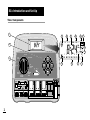
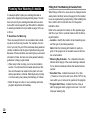
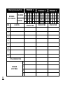
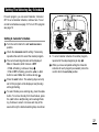
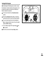
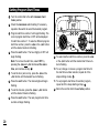
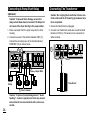
User’s Guide
TM
Automatic Sprinkler System Timer
ECx Features:
• Expandable Up To 8 Zones
With Plug-In Modules
• 3 Watering Programs With:
- Calendar and Interval Days
- 1 Min. to 4 Hrs. Zone Run Time
- 4 Start Times Per Day
• Battery Back-Up
• Automatic Pump Start
• Seasonal Run Time Adjust
• Rain Delay
• Rain Sensor Ready
• Snap-In Wire Connectors
AUTO / ON
RAIN
DELAY
SET TIME / DAY
ON
SEASON
ADJUST
MANUAL
START
SET
WATERING
DAYS
OFF
SET ZONE
RUN TIMES
SET
PROGRAM
START
TIMES
NEXT
OFF
PROGRAMS
R
TM
Table of Contents
Installation
■
ECx Introduction and Set Up
■
■
■
■
■
■
■
■
■
■
■
Timer Components .........................................2-5
Sprinkler System Basics ....................................6
Watering Program Basics ..................................7
Watering Program Details ..............................8-9
Planning Your Watering Schedule...................10
Filling Out The Watering Schedule Form ...10-11
❚ Watering Schedule Form ..............................12
“Remote” Programming ...................................13
Installing The Battery .......................................13
Selecting Optional Control Features................14
❚ 24-Hour Clock Mode .....................................14
❚ 15-Second Run Delay ..................................14
About The Timer Memory ................................14
Resetting The Timer Memory ..........................15
❚ To reset The Permanent Memory .................15
❚ To Clear The Memory ..................................15
Programming The Timer
■
■
■
■
Setting The Current Time And Day..................16
Setting The Watering Day Schedule ..........17-19
❚ Setting A Calendar Schedule ........................17
❚ Setting An Interval Schedule.........................18
❚ Turning A Program Off ..................................19
Setting Program Start Times ...........................20
Setting Zone Run Times ..................................21
■
■
■
■
Mounting The Timer.........................................22
Connecting The Valves....................................23
Connecting A Pump Start Relay ......................24
Connecting The Transformer...........................24
Connecting A Toro Rain Switch.......................25
Timer Operation
■
■
■
■
■
Automatic Operation .....................................26
Manual Operations ........................................27
❚ Starting Programs Manually..........................27
❚ Watering Control Features ............................28
❚ To Pause Watering .....................................28
❚ To Resume Watering ..................................28
❚ To Cancel Watering ....................................28
❚ To Skip Zones.............................................28
❚ To Adjust The Zone Run TIme ...................29
Turning Off The ECx........................................29
Using The Rain Delay Feature ........................29
Using The Season Adjust Feature...................30
Service and Specifications
■
■
■
■
■
■
Replacing The Fuse.........................................31
Adding A Zone Module ....................................32
Troubleshooting ...............................................32
Specifications...................................................33
Warranty Information .......................................33
FCC Rules .......................................................34
1
ECx Introduction and Set Up
Timer Components
1
A
1 2
2
C
B
3 4
D
F
E
PGM A B C
AM
PM
G
H
%
1
AUTO / ON
RAIN
DELAY
SET
PROGRAM
START
TIMES
SENSOR
OFF
ON
FUSE
OFF
PROGRAMS
9V Battery
NiCad
24 VAC
DELAY
24HR
MV/ PUMP COM
L
NEXT
12HR
SET ZONE
RUN TIMES
2
MANUAL
START
SET
WATERING
DAYS
SEASON
ADJUST
SENSOR
4
5
6
7
8
ON
OFF
ALK
3
SU MO TU WE TH FR SA
SET TIME / DAY
+
3
2
1
2
3
4
5
6
7
8
K
J
I
Timer Components
The following are brief descriptions of the ECx components and display elements. Each of these items will be
explained in further detail within the appropriate programming, operating and installation sections of this
guide.
1 - LCD Display
A - “Start Time” symbol – Alarm clock is displayed
when setting the program start times.
B - Program start time identification numbers 1–4.
C - Main display of various time values and prompts.
D - Program A, B and C identifiers.
E - “Watering On” symbol – Water droplet indicates a
watering zone is running. Droplet flashes if watering is paused.
F - “Watering Off” symbol – Water droplet with slash
indicates all watering activity is Off.
G - “Power Off” symbol – Displayed when 24 VAC is
disconnected and timer is on battery power only.
2 - Control Buttons
+/ON button – Increases the time display, scrolls forward through the program information and selects
watering days.
–/OFF button – Decreases the time display, scrolls
backward through the program information and
removes watering days.
button – Advances to the next portion of program information. Resumes watering if paused.
Advances through stations manually when watering.
NEXT
MANUAL START button – Selects and starts manual
watering operations.
3 - Control Dial – Selects all timer programming and
operation controls (except Manual Start).
Control Dial Positions
AUTO/ON
– Normal dial position for all automatic and
manual operations.
SET TIME/DAY
– Enables clock time and day to be set.
– Enables watering day schedules to be set and reviewed.
H - “Low Battery Voltage” symbol – Indicates low battery voltage (when transformer is disconnected).
SET WATERING DAYS
I - Watering Zone identification numbers.
SET PROGRAM START TIMES
J - “Percent” symbol– Indicates the Season Adjust feature is in use.
SET ZONE RUN TIMES
– Enables program start
times to be set and reviewed.
K - Day of the week identifiers.
set and reviewed.
L - “Run Time” symbol – Hourglass is displayed when
setting the watering zone run times.
(continued)
– Enables zone run time to be
3
Timer Components
– Selects the Season Adjust feature.
See page 30 for details.
10 - Pump/Master Valve Connection Terminal–
Snap-in connector for the power wire from the pump
start relay or master valve.
– Shuts off and prevents all automatic and manual watering activity. See page 29 for details.
11 - Valve Common Terminal – Snap-in connector for
the valve common wire.
3 - Control Dial Positions (continued)
SEASON ADJUST
OFF
RAIN DELAY–
Selects the Rain Delay feature.
See page 31 for details.
4 - Program Select Switch – Three position slide switch
used to select watering program A, B or C during the
programming procedures and manual operation.
5 - Fuse – 0.75 Amp, 250V Fast Blow fuse.
6 - Sensor Bypass Switch – Controls input from the
optional Toro Rain Switch (if installed). See page 25
for details.
7 - Battery Select Switch – Alkaline and NiCd position
to select the type of battery installed.
8 - Sensor Connection Terminals – Snap-in connectors for optional Toro Rain Switch control wires.
9 - Transformer Connection Terminals – Snap-in connectors for the transformer wires.
4
12 - Optional 12/24-Hour Clock Feature – A small wire
jumper which can be cut to select 24-hour
(military time) clock mode.
13 - Optional Run Delay Feature – A small wire jumper
which can be cut to select a 15-second delay period
before a zone starts watering.
14 - Plug-In Zone Control Module – Each control module has snap-in connectors for two zone control
valve power wires. Up to four modules can be
installed.
15 - 9-Volt Battery – The battery maintains the timer
memory if the transformer power is disconnected.
Either an Alkaline or NiCd battery can be installed.
16 - Transformer – Supplies 24 VAC power to the timer.
Plugs into a standard 120 VAC outlet.
See transformer specifications on page 33.
Timer Components
AUTO / ON
RAIN
DELAY
4
SET TIME / DAY
ON
SET
PROGRAM
START
TIMES
SEASON
ADJUST
SENSOR
FUSE
OFF
ON
6
NEXT
OFF
PROGRAMS
12HR
SET ZONE
RUN TIMES
5
MANUAL
START
SET
WATERING
DAYS
OFF
+
3
9V Battery
ALK
NiCad
DELAY
24HR
7
SENSOR
24 VAC
MV / PUMP COM
1
2
3
4
5
6
7
8
8
9
10
11
12
13
14
15
16
5
Sprinkler System Basics
The three main components of every automatic sprinkler
system are the timer, zone control valves and sprinklers.
The timer is the brain of the system, telling the control
valves when and how long to supply water to the sprinklers. The sprinklers direct and control the water applied to
the lawn and plants.
Each valve controls a specific group of sprinklers called
a watering zone. The zones are generally laid out and
installed according to the type of plant material to be
watered, the location plant within the landscape and the
maximum amount of water which can be supplied. Each
valve is connected to a numbered terminal within the
timer, identifying it as Zone 1, Zone 2, etc.
The timer operates the valves in order, one at a time. In
other words, one zone would water completely before
another zone would turn on. This is called a watering
cycle. The information stored in the timer memory which
determines when and how long the zones will water is
called a program.
The next section of this guide is very important. It
explains what a program is and how the ECx controls the
operation of the sprinkler system.
Valve 1
Timer
Valve 2
Valve 3
House
Valve 4
Valve 5
Valve 1 - Zone 1 - Parkway Lawn - Fixed Spray
Valve 2 - Zone 2 - Front Lawn - Fixed Spray
Valve 3 - Zone 3 - Front Shrubs - Flood Bubbler
Valve 4 - Zone 4 - Back Lawn - Geared Rotor
Valve 5 - Zone 5 - Garden - Drip
6
Watering Program Basics
A watering program requires three basic instructions to
operate automatically:
• What days to water –called watering days
• When to water – called a program start time
• How long to water – called zone run time
Watering Program Diagram
Program
Starts - 5:00 AM
Zone 1
12
6
The following example illustrates how a typical watering
program could be set for the sprinkler system shown on
the previous page.
Example: The program start time is set for 5:00 AM. Lawn
zones 1 and 2 each have a run time of 10 minutes and
lawn zone 4 is set to run for 20 minutes. Note that zones
3 and 5 water shrubs and flowers and have been excluded from this program. (These zones will be set to operate on separate programs).
As shown in the watering program diagram, at 5:00 AM
the timer starts the program watering cycle. Zone 1
sprinklers run for 10 minutes and shut off. Zone 2 sprinklers turn on, run for 10 minutes and shut off. The timer
skips zone 3 and turns on zone 4, which runs for 20 minutes and shuts off. Zone 5 is skipped and the watering
cycle ends at 5:40 AM.
As you can see from this example, only one program
start time was needed to operate three different zones.
Because of variations in plant watering needs, the ECx
provides three separate programs. The programs, called
A, B and C, are completely independent of one another
– like having three timers in one housing.
3
9
12
3
9
Zone 2
6
12
3
9
Zone 4
6
Program
Ends- 5:40 AM
Using more than one program for example, would enable
lawn zones to be watered every day on program A,
shrub zones to run on on Monday Wednesday and Friday on program B and drip irrigation to soak the flower
beds every three days on program C.
Although the ECx offers the multiple program feature,
you may want to have all zones on one program if it
meets your needs. The other programs can remain
turned off until you need to use them.
7
Watering Program Details
This section covers in detail each of the three parts of a
watering program – watering days, program start times
and zone run times.
Selecting Watering Days
The ECx provides three options for scheduling watering
days: Calendar, Interval and Off.
Calendar Schedule
A Calendar schedule enables you to select specific days
of the week to water, for example, Monday, Wednesday
and Friday. This is a seven-day schedule which starts on
Sunday and ends on Saturday.
This illustration shows how a Calendar schedule would
be displayed when the control dial is in the SET WATERING DAYS position.
In this example, program A
has watering days set for MO
(Monday), WE (Wednesday)
and FR (Friday).
PGM A
SU MO TU WE TH FR SA
Interval Schedule
An Interval schedule enables you to set watering days
without regard to the actual days of the week. For example, if you want to water every third day, you would
select a 3-day Interval.
8
Interval schedules range from 1-day (watering every
day) to 7-day (watering every seventh day). Once you
have selected an Interval schedule, you can choose
which day of the week will be the first day of the Interval.
The number of days in the Interval determines the available start days. For example, if you have selected a 3day Interval and today is Sunday, you may choose to
start the Interval today, Monday or Tuesday.
This illustration shows how
an Interval schedule would
be displayed. In this example, program B has a 3-day
Interval schedule which will
start on Monday.
PGM A B C
1
2
3
4
5
6
7
8
SU MO TU WE TH FR SA
Program Off
Selecting Off suspends the operation of the program
when it is not needed. Turning the program Off does not
alter or erase the Calendar or Interval schedule information of the program, it simply places the program on hold
until it is needed.
This illustration shows how a
program would be displayed
if its watering day schedule
is turned Off. In this example, program C is Off.
Selecting Program Start Times
Setting The Zone Run Time
A program start time is the time of day you select to
begin an automatic program watering cycle.
It is important to remember that a program only
requires one start time to operate automatically.
When a program starts, each zone assigned to a program will water in numerical order, one at a time for its
set run time.
A zone run time is the length of time the zone (controlled
by the valve) will water during the program watering
cycle. The run time for each zone can be set from Off
(no run time) to 4 hours, in one-minute increments.
Sometimes it is necessary to run a watering program
more than one time per day. For example, when growing
a new lawn. The ECx enables each program to have up
to four separate start times per day.
Program start times are numbered 1 through 4. These
numbers are shown at the top left of the display next to
the start time symbol
when the control dial is in the
SET PROGRAM START TIMES position and indicate how
many start times are currently set for the program.
This illustration shows how
a program start time is
displayed. In this example,
program A has one start
time (start time number 1)
set for 5:00 AM.
A zone is assigned to a program when it is given a run
time. If the run time for a zone is turned Off in a program,
it will not operate during the program watering cycle.
This is how the ECx enables you to assign watering
zones to different programs.
All zones assigned to the program are shown on the
lower portion of the display when the control dial is in
the SET ZONE RUN TIMES position.
This illustration shows how
a zone run time is displayed
for a program. In this example, zones 1–6 are assigned
to program A. Zone 1 has a
10-minute run time and
zone 2 is set to run for 25
minutes.
The zone run time being
displayed is identified by the
flashing zone number.
Flashing
Flashing
9
Planning Your Watering Schedule
It is always helpful to plan your watering schedule on
paper before beginning the programming steps. You will
have a record of your watering schedule and zone locations which can be kept with your ECx after it is installed.
A watering schedule form is provided on page 12 for you
to fill out.
•
Guidelines For Watering
There are several factors to be considered when deciding when and how long to water. For example, the content of your soil, the part of the landscape being watered,
climate conditions and the type of sprinklers being used.
Because of these variables, we cannot give you an exact
schedule to follow, but here are some general watering
guidelines to help you get started.
• Water early in the morning, one to two hours before
sunrise. You will have the best water pressure at this
time and the water can soak into the plant root zone
while evaporation is minimal. Watering during mid-day
or in the evening may cause plant damage or mildew.
• Watch for signs of under- or over-watering and make
program adjustments immediately.
10
Filling Out The Watering Schedule Form
When filling out this form, use a pencil so changes can be
easily made. Carefully remove the page from the booklet
to use as a guide during programming. After installing the
timer, fold the form in half and store it in the pocket
behind the timer.
Refer to the example form shown on the opposite page
and fill out your form in a similar manner with the following information:
• Location - Identify the location of each watering zone
and the type of plant being watered.
Note: Enter the following information for each program. If the program is not needed, leave its information column blank.
•
Watering Day Schedule - For a Calendar schedule,
indicate which day(s) of the week watering is desired.
For an Interval schedule indicate the desired Interval
number.
•
Zone Run Time - Indicate the amount of run time
(1 minute to 4 hours) for each zone. Write “Off” for any
zone which you do not want to operate in the program.
• Program Start Times - Indicate the time of day to
start the program. Each program can have 1 to 4 start
times per watering day.
(Example)
Watering Schedule Form
PROGRAM A
CALENDAR
WATERING
DAY SCHEDULE
ZONE
1
2
3
4
5
LOCATION
Parkway Lawn
Front Lawn
Front Shrubs
Back lawn
Garden
PROGRAM C
SU MO TU WE TH FR SA SU MO TU WE TH FR SA SU MO TU WE TH FR SA
1
INTERVAL
PROGRAM B
2
3
4
5
6
7
1
2
3
4
5
6
7
1
2
3
4
5
6
ZONE RUN TIME
ZONE RUN TIME
ZONE RUN TIME
10
10
Off
25
Off
Off
Off
5
Off
Off
Off
Off
Off
Off
1 hr
7
6
7
8
1
PROGRAM
START TIMES
2
3
4
5:00 AM
Off
Off
Off
4:00 AM
Off
Off
Off
6:00 AM
Off
Off
Off
11
Watering Schedule Form
PROGRAM A
CALENDAR
WATERING
DAY SCHEDULE
ZONE
LOCATION
2
3
4
5
6
7
8
TOTAL ZONE RUN TIME
1
PROGRAM
START TIMES
2
3
4
12
2
3
4
5
6
ZONE RUN TIME
1
PROGRAM C
SU MO TU WE TH FR SA SU MO TU WE TH FR SA SU MO TU WE TH FR SA
1
INTERVAL
PROGRAM B
7
1
2
3
4
5
6
ZONE RUN TIME
7
1
2
3
4
5
6
ZONE RUN TIME
7
If your home has frequent power interruptions, installing a
rechargeable NiCd battery is recommended.
Note: The battery does not supply power to operate the
zone control valves; power from the transformer must be
supplied.
Figure 1
Figure 2
7
OFF
SENSOR
6
7
12HR
The ECx can use either type of 9-volt battery: Alkaline or
rechargeable Nickel-Cadmium (NiCd). The Alkaline battery provided will keep the timer’s clock and programmable memory functioning for about 72 hours and should be
replaced every year. A fully-charged NiCd battery will last
about 24 hours, but is continuously recharged to provide
service for many years.
3. Slide the battery switch (7) to the left for Alkaline or
right to activate the NiCd battery charging circuit.
See Figure 2.
FUSE
ON
Installing The Battery
2. Insert the battery into the timer housing as shown in
Figure 1.
OFF
The ECx timer features the ability to be fully programmed
before installation. Installing its 9-volt battery brings the
ECx to life, so you can program your new timer while in
the comfort of your home.
1. Slide the lower housing cover toward the bottom of
the timer to remove. Locate the battery clip and attach
it to the battery terminals.
+
“Remote” Programming
9V Battery
ALK
NiCad
DELAY
24
8
9V
SENSOR
24 VAC
PUMP/MV CO
Caution: The battery switch (7) must be set correctly.
Damage to the timer can result from an Alkaline battery which may fail if charged.
4. Press the +/ON button to stop the display from flashing. The colon (:) will continually flash while displaying
the time and during watering operation.
13
Selecting Optional Features
About The ECx Memory
24-Hour Clock Mode
The ECx is set to display time in the 12-hour clock mode.
If you prefer to use a 24-hour clock mode (military time)
select this option by following the steps below.
15-Second Run Delay
The 15-second run delay feature is useful for sprinkler
systems utilizing a pump or master valve. For example, a
pump usually requires a few seconds to build pressure
after first turning on. With the 15-second run delay
selected, the pump would be running (or the master
valve would open) 15 seconds before the first zone
begins watering. A 15-second delay would also occur
between zone operations. This helps ensure that one
valve is closed before another valve opens.
Note: A 2-second run delay will occur if this option is not
selected.
1. Using small wire cutters,
clip jumper (13) to select
24-hour clock mode. Clip
jumper (12) to select
15-second run delay.
14
12HR
Caution: To prevent timer
damage, ensure transE
former is disconnected
during this procedure.
13
DELAY
24HR
12
The ECx has a permanent watering schedule within its
memory to assist you in two ways. First, it will restore
watering operation in case your watering program is lost
due to a power interruption lasting longer than the battery life. This prevents your landscape from going unwatered if the power outage occurs while you are away.
Secondly, if you do not want to program your ECx,
you may use the permanent watering schedule to
operate your sprinklers. Just set the current time
and day and your ECx will be ready to operate automatically.
The permanent watering schedule operates as follows:
When power is applied, the timer clock is set to 12:00 AM
Sunday. Program A has a Calendar watering schedule
set to water every day. One program start time is set for
5:00 AM (5:00) and a run time of 10 minutes is set for
each zone. Programs B and C are turned Off and have
no program start times or run times.
Note: An optional feature is provided which enables the
The ECx memory to be reset to the permanent program
or cleared completely if you choose. If you do not want to
use this option, skip the next procedure “Resetting The
Timer Memory” and continue at page 16 to begin programming.
Resetting The Timer Memory
The ECx program memory can be reset to the permanent program values or cleared completely at any time
without removing power.
Figure 3
2
Resetting the permanent program erases all user input
and replaces it with the permanent program values.
Clearing the program memory sets all program values to
Off (i.e., no active days, program start times or zone run
times). You may find that this simplifies programming the
timer if your watering requirements are quite different
than the permanent values.
3
AUTO / ON
RAIN
DELAY
SET TIME / DAY
ON
1
MANUAL
START
SET
WATERING
DAYS
OFF
SET
PROGRAM
START
TIMES
SEASON
ADJUST
SET ZONE
RUN TIMES
2
NEXT
OFF
PROGRAMS
Note: When power is first applied, the ECx will always
reset to the permanent program values.
To Reset The Permanent Program (Figure 3)
1
Turn the control dial to the OFF position. OFF will be
displayed.
2
Press the +/ON and –/OFF buttons at the same time
Figure 4
2
3
until CLR is displayed.
3
Return the control dial to the AUTO/ON position.
SET TIME / DAY
ON
1
1
Turn the control dial to the OFF position. OFF will be
displayed.
2
Press the +/ON and –/OFF buttons at the same time
3
Return the control dial to the AUTO/ON position.
MANUAL
START
SET
WATERING
DAYS
OFF
To Clear The Memory (Figure 4)
2
AUTO / ON
RAIN
DELAY
SEASON
ADJUST
SET ZONE
RUN TIMES
SET
PROGRAM
START
TIMES
NEXT
OFF
PROGRAMS
until CLR 0 is displayed.
15
Programmimg The Timer
Setting The Current Time and Day
1
Turn the control dial to the SET TIME/DAY position.
The hour digits will begin flashing.
2
To set the current hour (and AM/PM), press the +/ON
button to scroll forward or the –/OFF button to scroll
backward.
1 2
SU
7
scroll forward or the –/OFF button to scroll backward.
16
5
Press the NEXT button. The weekday abbreviation
will begin flashing.
6
To set the current day of the week, press the +/ON
button to scroll forward or the –/OFF button to scroll
backward until the current day is displayed.
The weekday abbreviations are as follows:
SU (Sunday)
MO (Monday)
TU (Tuesday) WE (Wednesday)
TH (Thursday) FR (Friday) SA (Saturday)
SET TIME / DAY
ON
1
SEASON
ADJUST
SET ZONE
RUN TIMES
7
MANUAL
START
SET
WATERING
DAYS
OFF
Press the NEXT button. The minute digits will begin
flashing.
4 To set the current minute, press the +/ON button to
2 4 6
5 6
AUTO / ON
RAIN
DELAY
Note: The display will begin to change rapidly if
either button is held down for more than two seconds.
3
3 4
SET
PROGRAM
START
TIMES
NEXT
3 5
OFF
PROGRAMS
2 4 6
When the current time and day are displayed, return
the control dial to the AUTO/ON position.
Setting The Watering Day Schedule
For each program, you can select Calendar, Interval or
Off. To set a Calendar schedule, continue here. To set
an Interval schedule see page 18. To turn Off a program
see page 19.
PGM A
7
SU MO TU WE TH FR SA
AUTO / ON
RAIN
DELAY
SET TIME / DAY
WATERING DAYS
2
Check the PROGRAMS switch setting. If necessary,
reposition the switch to select the desired program.
3
The current watering schedule will be displayed:
CAL for Calendar, Int for Interval or OFF
• If CAL is flashing, continue at step 4 .
• If Int or OFF is flashing, press the +/ON or –/OFF
button to select CAL, then continue at step 4 .
4
Press the NEXT button. The watering days currently
set for this program will be displayed. SU (Sunday)
will begin flashing.
5
To select Sunday as a watering day, press the +/ON
button. To remove Sunday from the schedule, press
the –/OFF button. MO (Monday) will now begin flashing. Continue to select or remove each day of the
week until only the desired watering days are shown.
3 5
5
ON
MANUAL
START
SET
WATERING
DAYS
OFF
Turn the control dial to the SET
position.
4
1
Setting A Calendar Schedule
1
2
3
SEASON
ADJUST
SET ZONE
RUN TIMES
SET
PROGRAM
START
TIMES
NEXT
4
OFF
PROGRAMS
2
3 5
6. To set a Calendar schedule for another program,
repeat all of the steps beginning at step 2 .
7
When you have completed setting the Calendar
schedule for each program (as needed) return the
control dial to the AUTO/ON position.
17
Setting An Interval Schedule
1
Turn the control dial to the SET
position.
2
Check the PROGRAMS switch setting. If necessary,
reposition the switch to select the desired program.
3
4
WATERING DAYS
Press the NEXT button. The current Interval number
(1–7) will begin flashing. The day of the week on
which the Interval will start will be shown.
5
To change the Interval number, press the +/ON or
–/OFF button until the desired number is flashing.
6
Press the NEXT button. The Interval start day will
begin flashing.
7
To change the Interval start day, press the +/ON
button or the –/OFF button until the desired day is
flashing.
2
PGM A
3
9
The current watering schedule will be displayed:
CAL for Calendar, Int for Interval or OFF.
• If CAL or OFF is displayed, press the +/ON or –/OFF
button to select Int, then continue at step 4 .
• If Int is displayed, continue at step 4 .
8. To set an Interval schedule for another program,
repeat all of the steps beginning at step 2 .
18
3
MO
6 7
AUTO / ON
RAIN
DELAY
ON
1
MANUAL
START
SET
WATERING
DAYS
OFF
SEASON
ADJUST
SET ZONE
RUN TIMES
9
3 5 7
4 5
SET TIME / DAY
SET
PROGRAM
START
TIMES
PROGRAMS
2
NEXT
4 6
OFF
3 5 7
When you have completed setting the Interval
schedule for each program (as needed) return the
control dial to the AUTO/ON position.
Turning Off A Program
Note: Selecting the Off setting does not alter or erase
the Calendar or Interval schedule of the program, it simply places the program on hold until the Calendar or
Interval schedule is reselected.
1
2
3
Turn the control dial to the SET
position.
3
2
PGM
B
5
WATERING DAYS
Check the PROGRAMs switch setting. If necessary,
reposition the switch to select the desired program.
The current watering schedule will be displayed:
CAL for Calendar, Int for Interval. Press the +/ON or
–/OFF until OFF is flashing.
3
AUTO / ON
RAIN
DELAY
SET TIME / DAY
ON
1
MANUAL
START
SET
WATERING
DAYS
OFF
SEASON
ADJUST
SET ZONE
RUN TIMES
SET
PROGRAM
START
TIMES
PROGRAMS
2
NEXT
OFF
3
4. To turn another program Off, repeat steps 2 and
3 as needed.
5
Return the control dial to the AUTO/ON position.
19
Setting Program Start Times
1
Turn the control dial to the SET
position.
PROGRAM START
2
9
3
TIMES
2
3
4
12
Program start time number 1 will begin flashing. The
current program start time or OFF will be displayed
for start time number 1. To select a different program
start time number, press the +/ON or the –/OFF button
until the desired number is flashing.
Press the NEXT button. The hour digit(s) or OFF will
begin flashing.
PGM A
AM
Check the PROGRAMS switch setting. If necessary,
reposition the switch to select the desired program.
Note: To remove the start time, select OFF by
pressing the +/ON and –/OFF buttons at the same
time, and continue at step 8 .
20
1 2
4 5
AUTO / ON
RAIN
DELAY
9
ON
MANUAL
START
SET
WATERING
DAYS
OFF
SEASON
ADJUST
SET ZONE
RUN TIMES
9
3 5 7
6 7
SET TIME / DAY
SET
PROGRAM
START
TIMES
NEXT
4 6 8
1
OFF
PROGRAMS
2
3 5 7 9
To select another start time number, press the +/ON
or the –/OFF button until the desired start time number is flashing.
5
To set the hour (and AM/PM), press the +/ON or the
–/OFF button until the desired hour is flashing.
10. To set, change or remove a program start time for
the start time number selected, repeat all of the
steps starting at step 4 .
6
Press the NEXT button. The minute digits will begin
flashing.
11. To set program start times for another program,
repeat all of the steps starting at step 2 .
7
To set the minutes, press the +/ON or –/OFF button
until the desired minute is flashing.
12 Return the control dial to the AUTO/ON position.
8
Press the NEXT button. The next program start time
number will begin flashing.
Setting Zone Run Times
1
Turn the control dial to the SET
position.
2
Check the PROGRAMS switch setting. If necessary,
reposition the switch to select the desired program.
ZONE RUN TIMES
2
4 5
PGM A
3
Zone number 1 will be flashing and its current run
time or OFF will be shown. To select a different zone
number, press the +/ON or the –/OFF button until the
desired zone number is flashing.
4
Press the NEXT button. The run time (or OFF) will
begin flashing.
5
To set the run time, press the +/ON or the –/OFF button until the desired run time is shown.
1
9
3
4 5 6
3 5
3
AUTO / ON
RAIN
DELAY
2
SET TIME / DAY
ON
MANUAL
START
SET
WATERING
DAYS
OFF
SEASON
ADJUST
SET ZONE
RUN TIMES
1
SET
PROGRAM
START
TIMES
NEXT
4 6
OFF
PROGRAMS
2
3 5
Note: To remove the run time, select OFF by pressing the +/ON and –/OFF buttons at the same time.
6
Press the NEXT button. The next zone number will
begin flashing.
7. Repeat steps 5 and 6 as needed to set, change,
or remove the run time for the remaining zones.
8. To set the zone run time for another program, repeat
all of the steps starting at step 2 .
9
Return the control dial to the AUTO/ON position.
21
Installation
A
Note: The ECx timer is not weather resistant and
must be installed indoors or in a protected area. For
outdoor installation, an optional weather-resistant outdoor cabinet (model # 53335) is available.
B
Mounting The Timer
C
1. Select a location for the timer within 4' (1.2m) of an
electrical outlet to enable the transformer wires to
easily reach. Make sure the outlet is not controlled by
a light switch.
2. Remove the mounting bracket attached to the back
of the timer housing by pulling the lower edge of the
bracket away and downward from the timer housing.
D
3. Place the mounting bracket (A) against the wall aligning the top edge at about eye level. Drive three 1"
(25mm) wood screws (B) into the wall through the
three holes provided in the bracket.
Note: If you are installing the bracket on drywall or
masonry, install screw anchors (C) to prevent screws
from loosening.
4. Align the slotted openings on the back of timer housing with the mounting bracket tabs. Slide the timer
downward to engage the tabs.
22
Note: Store the Quick Reference Guide and the
Watering Schedule Form in the pocket (D) between
the timer and bracket.
Connecting The Valves
2. Attach the white color-coded wire from the cable to
one wire from each valve solenoid. (Either solenoid
wire can be used for this connection.) This is called
the valve common wire.
3. Attach a separate cable wire to the remaining wire
from each valve solenoid. Make a note of the wire
color code used for each valve and the watering zone
it controls. You will need to have this information
when connecting the valve wires to the timer.
4. Use screw-on wire fasteners to secure each wire connection. Waterproof all connections with grease caps
or simular insulation method.
5. Route the wire cable into the timer. Strip insulation
back 1/2" (13mm) from all cable wires.
Note: The ECx has snap-in wire terminals. To attach
wires, simply raise the lever, insert the stripped wire,
and press the lever down to secure.
SENSOR
FUSE
ON
OFF
Note: Using 18 AWG (0.75 mm2) multi-wire sprinkler
valve connection cable is recommended. This cable
is insulated for direct burial and is color-coded to simplify installation.
11
14
12HR
10
1. Route the valve control wires between the valves and
the timer.
9V Battery
ALK
NiCad
SENSOR
24VAC
DELAY
1
1
Master
Valve
24HR
2
3
4
2
Valve Common
5
3
6
7
8
4
Zone Valves
6. Referring to the Timer Components on page 5 and the
diagram above, secure the valve common wire to the
terminal labeled COM (11). Connect the individual
zone valve wires to the appropriate zone module terminals (14). Connect the master valve wire (if applicable) to the terminal labeled PUMP/MV (10).
Note: Connecting a master valve (or pump relay) is
optional and may not be required in your sprinkler
system.
23
Connecting The Transformer
1. Route a wire pair from the pump relay into the timer
housing
2. Connect one wire to the terminal labeled COM (11).
Connect the remaining wire to the terminal labeled
PUMP/MV (10) as shown below.
ON
FUSE
2. Connect one transformer cable wire to each terminal
labeled 24 VAC (9). The wires can be connected to
either terminal.
SENSOR
FUSE
9V Battery
NiCad
DELAY
24HR
9
11
12HR
10
SENSOR
1. Ensure the transformer is unplugged.
12HR
Caution: To prevent timer damage, ensure the
relay current draw does not exceed 0.35 Amps. Do
not connect the timer directly to the pump starter.
Caution: Do not plug the transformer into an electrical outlet until all of the wiring procedures have
been completed.
ON
(Optional)
OFF
Connecting A Pump Start Relay
SENSOR
24VAC
PUMP/MV COM
1 2
3 4
OFF
9V Battery
ALK
NiCad
SENSOR
24VAC
DELAY
24HR
1
2
3
4
5
6
7
8
Jumper Wire
Pump
Relay
1
2
3
Valve Common
Caution: To prevent pump damage due to “deadheading”, connect a jumper wire from any unused
zone terminal to a zone terminal with a valve connected.
24
Transformer
5
6
7
Connecting A Toro Rain Switch
The Toro Rain Switch (model # 53221) is a remote rain
sensing device which can be connected directly to your
ECx to automatically interrupt watering during rain.
A sensor bypass switch is provided in the ECx which
enables the Rain Switch operation to be turned On and
Off.
When the Rain Switch absorbs rain water it automatically
signals the ECx to suspend all watering operations. The
“No Watering” symbol will appear in the upper right
corner of the display until the Rain Switch drys out and
automatically resets. The “No Watering” symbol will disappear and timer operation will resume as programmed.
SENSOR
FUSE
ON
OFF
6
12HR
(Optional)
9V Battery
ALK
NiCad
SENSOR
24VAC
DELAY
24HR
8
24VAC
Toro Rain Switch
1. Route the wire cable from Toro Rain Switch into the
timer housing with the valve wires.
2. The Rain Switch cable has four wires: two copper
wires and two silver wires. Only two of the wires are
used. Connect the heavier 18 AWG (0.75mm2) copper
wire and the thin 24 AWG (0.50mm2) silver wire to the
terminals labeled SENSOR (8). Trim off the remaining
two cable wires.
3. Set Sensor Switch (6) as required: ON allows the
Rain Switch to interrupt watering; OFF bypasses the
Rain Switch input.
25
Timer Operation
The ECx timer has three modes of operation: Automatic,
Manual and Off. In the Automatic mode the timer tracks
the time and day and operates the automatic watering
schedules. The Manual mode enables the watering programs to be started and controlled manually at any time.
The Off mode shuts off all watering activity and prevents
any zones from operating automatically or manually.
This illustration shows the
status display. In this
example the current time is
2:45 PM and the current
day is Monday. Programs
A and B are active on
Monday.
The Rain Delay and Season Adjust control features are
provided to enable quick, temporary changes in operation
to help compensate for variables in weather and season.
When watering starts, the operating display appears and
is shown for the duration of the program.
Each of the operating modes and control features are
explained in this section of the guide and can be found
on the following pages:
•
•
•
•
•
Automatic Operation, page 26
Manual Operations, page 27 & 28
Turning Off The ECx, page 29
Using the Rain Delay Feature, page 29
Using the Season Adjust Feature, page 30
Automatic Operation
26
The Automatic mode is selected when the control dial is
in the AUTO/ON position. While in the automatic mode,
the display will show two types of information:
status and operation.
In the Automatic mode, the ECx keeps track of the current time, day of the week and the automatic watering
program schedule. Automatic operation will occur whenever a programmed watering day and start time match
the current time and day.
In this example, program A
is operating. Zone 1 is
watering and has 10 minutes of run time remaining.
Zones 2, 3 and 4 will operate during this program.
PM
MO
Flashing
Flashing
Note: If the control dial remains in any other position
(except OFF) for more than 8 minutes, the timer reverts to
the Automatic mode.
The PROGRAMS switch is not functional in the Automatic
Mode.
Manual Operation
Manual control operations enable the automatic watering
programs to be started at any time. During operation
temporary changes can be made to increase or
decrease zone run time, step through the watering zone
sequence and pause or stop watering. Upon completion
of a manual watering operation the timer will return to the
Automatic mode.
Flashing
PGM A B
Flashing
1
Watering programs can be started individually or set to
start in order. When one program finishes the next
selected program will operate.
1
Ensure the control dial is in the AUTO/ON position.
2
Position the PROGRAMS switch to select a program
you wish to start.
3
Press the MANUAL
START
2
3
4
4
AUTO / ON
RAIN
DELAY
SET TIME / DAY
ON
3 5
MANUAL
START
SET
WATERING
DAYS
OFF
Starting Programs Manually
1
SEASON
ADJUST
SET ZONE
RUN TIMES
SET
PROGRAM
START
TIMES
NEXT
OFF
PROGRAMS
2
4
Example: Program A is operating. Program B will start
when program A is finished.
button.
4. To select additional programs, repeat step 2 and 3 .
Note: Additional programs set to start will operate
one at a time in alphabetical order regardless of the
order they were selected. Each program letter will be
displayed as it is selected. The program currently
operating is indicated by the flashing letter.
27
Watering Control Features
The following watering control features enable you to further control the watering program during operation.
All watering control features apply to watering programs
started manually and automatically.
To Pause Watering
To Cancel Watering
Press the +/ON and –/OFF buttons at the same time two times.
• All watering operations will be canceled and the timer
will return to the automatic mode.
Note: Placing the control dial in the OFF position for
two seconds, then back to AUTO/ON will also cancel
all watering operations.
Press the +/ON and –/OFF buttons at the same time.
• The zone currently watering will shut off.
To Skip Zones
• The “Watering On” symbol will begin flashing.
Press the NEXT button one time.
• The display will show the amount of run time remaining for the paused zone.
Note: If watering is not resumed within 8 minutes, all
watering operations will be canceled and the timer will
return to the automatic mode.
• The zone currently watering will shut off and the next
zone will start.
• If the last zone is skipped, the program will end. If
additional programs have been set to operate the
next program in alphabetical order will start.
To Resume Watering (when paused)
To Adjust The Zone Run Time
Press the NEXT button.
Press the +/ON button to increase run time or the –/OFF
button to decrease run time.
• Watering activity will resume from the point of interruption.
• If the zone run time is decreased to less than 1
minute, the zone will shut off. The next zone in
sequence will start.
• The zone run time is changed during this operation
only. The program memory will not be changed.
28
Turning Off The ECx
When the control dial is turned to the OFF position, the
timer immediately shuts off any watering operation currently in progress. Leaving the control dial in the OFF
position will prevent all automatic and manual watering
operations. The timer will continue to track the current
time and day of the week.
Flashing
PGM A
PM
3
1
2
AUTO / ON
For extended shutdown of the
sprinkler system leave the control
dial in the OFF position.
The word OFF will be displayed
for 8 minutes. The automatic status display will then appear with
the “No Watering” symbol as
shown in this illustration.
MO
RAIN
DELAY
SET TIME / DAY
ON
MANUAL
START
SET
WATERING
DAYS
OFF
SEASON
ADJUST
SET ZONE
RUN TIMES
SET
PROGRAM
START
TIMES
NEXT
OFF
PROGRAMS
2
PM
1
Turn the control dial to the RAIN DELAY position. The
rain delay display will begin alternating with the automatic status display.
2
To set the number of rain delay days, press the +/ON
or –/OFF button until the desired number (1–7) is
flashing.
3
Return the control dial the control to the AUTO/ON
position.
MO
Automatic operation is resumed by turning the control
dial to the AUTO/ON position.
Using The Rain Delay Feature
This feature enables all watering operations to be
delayed from 1 to 7 days. For example, rain is forecast in
your area for the next two days. Instead of turning the
timer off (and possibly forgetting to turn it back on), a
rain delay of 3 days can be easily entered. At the end of
3 days, the timer will resume automatic operation as
scheduled.
Note: The rain delay number will automatically
decrease as each day passes. When the number
reaches 0 (zero), automatic operation will resume at
the next scheduled start time.
To cancel the rain delay, turn the control dial
momentarily (3 seconds) to the OFF position.
29
Using The Season Adjust Feature
Changes in season and temperature generally require a
change in zone run time to maintain a healthy landscape
and conserve water. The season adjust feature enables
you to change the run time of all zones assigned to a program, simultaneously up or down, in 10% increments –
with just the press of a button. Adjustments can be
reduced to 10% or increased to 200% of the programmed
run time of each zone.
A 50% setting, for example, would decrease a 20-minute
zone run time to 10 minutes. Increases however, work a
little differently. With any adjustment above 100%, the
ECx will first increase the run time by the adjustment
percentage, then split the time in half and run the watering program twice. This allows the water to soak-in
instead of pooling or running off. For example, adjusting
to 150% would first increase a 20-minute zone run time
to 30 minutes, then split the time in half and run two
watering cycles back-to-back with 15 minutes in each
operation. During operation the % symbol will flash to
indicate a multiple watering operation.
Note: All zone run times are retained in the timer memory
and returned to their set value when the season adjust is
reset to 100%. The only time a zone run time will appear
changed is during operation.
30
PGM A
%
5
3
AUTO / ON
RAIN
DELAY
SET TIME / DAY
ON
MANUAL
START
SET
WATERING
DAYS
OFF
1
SEASON
ADJUST
SET ZONE
RUN TIMES
SET
PROGRAM
START
TIMES
NEXT
OFF
PROGRAMS
2
3
1
Turn the control dial to the SEASON ADJUST position.
The season adjust display will be shown and 100%
will be flashing.
2
Check the PROGRAMs switch setting. If necessary,
reposition the switch to select the desired program.
3
Press the +/ON or –/OFF until the desired adjustment
value is flashing.
4. To apply the Season Adjust feature to another program, repeat steps 2 and 3 .
5
Return the control dial the AUTO/ON position.
Service and Specifications
Adding A Zone Module
1. Turn the control dial to the OFF position.
A 0.75 Amp fuse protects the timer from damage due to
power surges and excessive current draw through the
Zone Modules. Before replacing the fuse, check for the
probable cause, such as a shorted or improperly connected control valve wire, then replace the fuse as follows:
1. Unplug the transformer from the wall receptacle.
WARNING
REMOVE TRANSFORMER FROM POWER SOURCE
PRIOR TO SERVICING THE FUSE. FAILURE TO
COMPLY MAY RESULT IN INJURY AND/OR DAMAGE TO TIMER.
12HR
Replacing The Fuse
2. Remove the lower front cover from the timer housing
by sliding it downward.
FUSE
NiCad
DELAY
24HR
4VAC
7 8
3. Place the back of the zone module squarely between
the guides of the first open expansion slot (from left to
right). Pushing lightly on the bottom of the module,
slide it upward until it locks into position.
2. Remove the lower front cover from the timer housing
by sliding it downward.
4. To connect the valve wires, refer to “Connecting The
Valves” on page 23.
3. Carefully remove the blown fuse from the retaining
clip.
5. Install the lower front cover.
4. Remove the replacement fuse from the back side of
lower cover and install it into fuse retaining clip.
CAUTION: Never install a higher amperage fuse!
Severe damage to the timer can result.
6. To set the zone run time, refer to “Setting Zone Run
Times” on page 21.
7. To test the operation of the new watering zone(s),
refer to “Manual Operations” on pages 27 and 28.
5. Install the lower front cover.
6. Plug the transformer into the wall receptacle.
31
Troubleshooting
If you are having a problem with the timer, check the following symptoms, possible causes and remedies. If
the problem cannot be resolved or you would like assistance with any Toro irrigation product, call our toll-free
Toro Help Line, 1-800-367-8676 Monday through Friday, 7:30 AM – 4:00 PM (Pacific Standard Time)
32
Symptom
Possible Cause
Remedy
The display is blank and the
timer does not operate.
The battery is dead and one or more
of the following causes:
Replace the battery and one or
more of the following:
Blown fuse.
Replace the fuse. See page 31.
Transformer wires disconnected or
the transformer is unplugged.
Check the transformer connections.
Open circuit breaker to wall plug
receptacle.
Check circuit breaker at service.
Watering programs start at
unscheduled times.
Watering programs have overlapping
schedules.
Shorten zone run times and/or
space start times farther apart.
Watering zone does not turn on.
Faulty control valve wire connections.
Check the wire connections at the
control valve and controller.
Zone run time is turned Off.
Enter a zone run time. See page 21.
Watering zone does not turn off.
Control valve problem.
Inspect, clean and/or replace the
valve solenoid.
Program restarts unexpectedly
after the completion of an automatic operation.
More than one start time on the
program.
Remove additional program start
times. See page 22.
Season Adjust setting greater than
100%.
Set Season Adjust to 100%. See
page 32.
Specifications
Warranty
Transformer: Plug-In Class 2, UL Listed, CSA Certified
The Toro Promise – Limited One Year Warranty
Input: 120 VAC 50/60 Hz
The Toro Company warrants, to the owner, each new piece of equipment
(featured in the current catalog at date of installation) against defects in
material and workmanship provided they are used for irrigation purposes
under manufacturer’s recommended specifications for the period
described below. Product failures due to acts of God (i.e., lightning, flooding, etc.) are not covered by this warranty.
Output: 24 VAC 50/60 Hz; 0.75 Amps
Fuse: 0.75 Amp, Fast Blow – Protects AC Return
Maximum Load Per Zone:
0.35 Amps @ 24 VAC @ 140° F
Maximum Load For Pump/Master Valve:
0.35 Amps @ 24 VAC @ 140° F
Total Maximum Output: 1 Zone plus Pump,
not to exceed 0.70 Amps @ 24 VAC @ 140° F
Battery Type and Back-Up Duration:
9-Volt Alkaline – 72 hrs. or 9-Volt NiCad – 24 hrs.
Recommended Control Valve Wire Size:
18 AWG (0.75 mm2)
Housing: Plastic, indoor, wall mount,
8" W x 8" H x 2" D (20cm W x 20cm H x 5cm D)
Toro is not liable for failure of products not manufactured by Toro even
though such products may be sold or used in conjunction with Toro products.
During such warranty period, Toro will repair or replace, at its option, any
part found to be defective. Toro’s liability is limited solely to the replacement or repair of defective parts. All other express and implied warranties
are specifically disclaimed.
Return the defective part to the place of purchase.
This warranty does not apply where equipment is used, or installation is
performed, in any manner contrary to Toro’s specifications and instructions, nor where equipment is altered or modified.
Toro is not liable for indirect, incidental or consequential damages in
connection with the use of equipment, including but not limited to:
vegetation loss, the cost of substitute equipment or services
required during periods of malfunction or resulting non-use, property damage or personal injury resulting from installer’s actions,
whether negligent or otherwise.
All implied warranties, including those of merchantability and fitness
for use, are limited to the duration of this express warranty.
This warranty gives you specific legal rights and you may have other
rights which vary from state to state.
33
FCC Rules
Note: This equipment has been tested and found to comply with the limits for a Class B digital device, pursuant to
Part 15 of the FCC Rules. These limits are designed to
provide reasonable protection against harmful interference in a residential installation. This equipment generates, uses and can radiate radio frequency energy and, if
not installed and used in accordance with the instructions,
may cause harmful interference to radio communications.
However, there is no guarantee that interference will not
occur in a particular installation. If this equipment does
harmful interference to radio or television reception,
which can be determined by turning the equipment off
and on, the user is encouraged to try to correct the interference by one or more of the following measures:
Printing Date
March 1996 Rev. A
1. Reorient or relocate the receiving antenna.
2. Increase the separation between the equipment and
receiver.
3. Connect the equipment into an outlet on a circuit different from that to which the receiver is connected.
4. Consult the dealer or an experienced radio/TV technician for help.
The user may find the following booklet prepared by the
Federal Communications Commission helpful:
“How To Identify and Resolve Radio-TV Interference
Problems”. This booklet is available from the U.S.
Government Printing Office, Washington, DC 20402.
Stock No. 004-000-00345-4.
© 1996 THE TORO COMPANY
Irrigation Division • Riverside, California
Form No.
370-0050