1
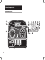
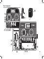
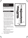
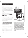
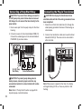
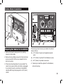
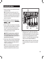
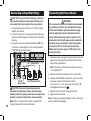
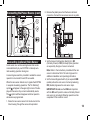
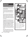
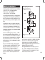
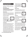
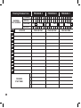
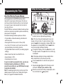
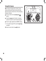
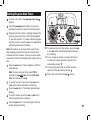
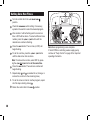
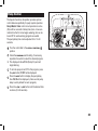
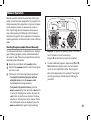
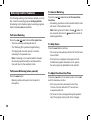
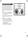
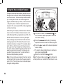
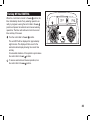
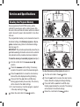
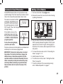
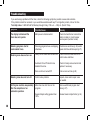
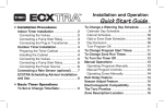
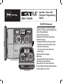
User’s Guide Sprinkler Timer with Computer Programming Option ECXTRA Features ON MANUAL START NEXT A B C OFF ON MANUAL START NEXT OFF OUTDOOR MODEL INDOOR MODEL •Easily expandable to 10 Zones (Indoor model) or 12 Zones (Outdoor Model) with 2-zone Plug-in Modules •Snap-in Wire Connectors •Compatible with Optional Scheduling Software Package •3 Independent Watering Programs with: - Calendar, Interval and Odd/Even Days - Selective Day Exclusion - 1-minute to 4-hour Zone Run Time - 4 Start Times •Seasonal Run Time Adjust •Rain Delay •Compatible with Normally Closed or Normally Open Rain Sensors •Automatic 24 VAC Circuit Protection •Program Memory Backup without Battery •Programmable Pump Start Notes: Table of Contents Timer Components. ....................................... 2-5 Timer Installation n Indoor Model Installation................................. 6 z Connecting the Valves.................................... 7 z Connecting a Pump Start Relay...................... 8 z Connecting the Transformer............................ 8 n Outdoor Model Installation.............................. 9 z Preparing the Cabinet for Installation.............. 9 z Installing the Cabinet..................................... 10 z Connecting the Valves.................................. 11 z Connecting a Pump Start Relay.................... 12 z Connecting the Power Source....................... 12 n Connecting a Rain Sensor............................ 13 Getting Started n Automatic Sprinkler System Basics............. 14 n Watering Schedule Basics............................ 15 n Watering Program Details........................ 16-17 z Selecting Watering Days............................... 16 z Selecting Program Start Times..................... 17 z Setting the Zone Run Time........................... 17 n Planning Your Watering Schedule............... 18 z Watering Schedule Forms........................ 19-20 an Odd or Even Schedule................. 24 the Day Exclusion Feature.................. 25 n Turning Off a Program................................... 26 n Setting Program Start Times......................... 27 n Setting Zone Run Times................................ 28 n Pump Control................................................. 29 z Setting z Using Timer Operation n Automatic Operation...................................... 30 Operation........................................... 31 z Starting Programs and/or Zones Manually.... 31 n Watering Control Features............................ 32 z To Pause Watering........................................ 32 z To Resume Watering.................................... 32 z To Cancel Watering....................................... 32 z To Skip Zones............................................... 32 z To Adjust the Zone Run Time....................... 32 n Using the Rain Delay Feature....................... 33 n Using the Season Adjust Feature................. 34 n Turning Off the ECXTRA............................... 35 n Manual Service and Specifications n Clearing Programming the Timer the Watering Program Memory......... 21 the Current Time and Date............... 21 n Setting the Watering Day Schedule......... 22-24 z Setting a Calendar Schedule......................... 22 z Setting an Interval Schedule......................... 23 the Program Memory...................... 36 n Automatic Circuit Protection........................ 37 n Adding a Zone Module................................... 37 n Troubleshooting............................................. 38 n Specifications................................................. 39 n About n Setting Glossary of Terms..................................... 39-41 Warranty............................................................. 42 Electromagnetic Compatibility. ............... 42 Timer Components Timer Components B ON MANUAL START NEXT OFF SENSOR 24 VAC F Timer Components The following are brief descriptions of the timer components and display elements. Each of these items will be explained in further detail within the appropriate programming, operating and installation sections of this guide. 1 - LCD Display A -“Start Time” symbol is displayed when setting the program start times. button – Advances to the next portion of program information. Resumes watering if paused. Advances through stations manually when watering. next 3 - Control Dial – Selects all controller programming and operation controls (except Manual Start). E -“Watering On” symbol is displayed when a watering zone is running. Symbol blinks when watering is paused. –/off button – Decreases the time display, scrolls backward through the program information and removes watering days. D -Program A, B and C identifiers. +/on button – Increases the time display, scrolls forward through the program information and selects watering days. C -Main display of various time values and prompts. B -Program start time identification numbers 1–4. 2 - Control Buttons F -“Watering Off” symbol is displayed when the Rain Delay feature is active. G -“Percent” symbol is displayed when the Season Adjust feature is in use. H -Watering zone identification numbers. I - Day-of-the-week identifiers. J - “Run Time” symbol is displayed when setting the watering zone run times. button – Selects and starts manual watering operations. manual start Control Dial Positions run current time/day – The normal dial position for all automatic and manual operations. day to be set. – Enables the clock time and – Enables the watering day schedules to be set and reviewed. watering days – Enables the program start times to be set and reviewed. start times – Enables the watering zone run time to be set and reviewed. set zone times (continued) Timer Components 3 - Control Dial Positions (continued) – Enables the run time of all stations in a program to be simultaneously increased or decreased in 10% increments. season adjust special functions rain delay – Provides optional control and timing features for pump operation. – Enables all watering operations to be delayed from 1 to 7 days. off – Shuts off and prevents all automatic and manual watering activity. 4 - Program Select Switch – Three-position slide switch used to select watering program A, B or C during the programming procedures and manual operation. 5 - Sensor Bypass Switch – Controls the rain sensor input circuit. Switch positions provided for sensor circuit Enable and Disable (bypass). 6 - Rain Sensor Configuration Switch – Selects either Normally Open (NO) or Normally Closed (NC) sensor operation. 7 - Sensor Connection Terminals – Snap-in wire connectors for (optional) rain sensor. 8 - Transformer Connection Terminals – Snap-in connectors for the plug-in transformer wires. 9- Pump/Master Valve Connection Terminal – Snap-in wire connector for a pump start relay or master valve. 10 - Valve Common Connection Terminal – Snap-in wire connector for the valve common wire. 11 - Plug-in 2-zone Module – Each 2-zone module provides snap-in connectors for two separate zone control valve power wires. Up to six modules (12 zones) can in the installed in the outdoor timer model and five modules (10 zones) in the indoor model. 12 - Time PodTM Port – Accepts the (optional) ECXTRA Time Pod unit to transfer Toro computer-aided watering schedule data from your PC to the ECXTRA timer. 13 - Power Supply (indoor models only) – 120/24 VAC plug-in transformer. 14 - Terminal Block – (outdoor models only) – Connection terminals for 120 VAC power wires. Timer Components ON MANUAL START NEXT OFF 24VAC Pump/MV COM ON MANUAL START NEXT A B C OFF A Timer Installation F B Note: The ECXTRA indoor timer is not weather resistant and must be installed indoors or in a protected area. Indoor Model Installation C 1. Select a location for the timer within 4′ (1,2m) of an electrical outlet to enable the transformer cord to easily reach. Make sure the outlet is not controlled by a light switch or used to power any large appliance such as a refrigerator, freezer, or air conditioner. 2. Remove the mounting bracket attached to the back of the timer housing by pulling the lower edge of the bracket away and downward from the timer housing. 3. Place the mounting bracket (A) against the wall aligning the top edge at about eye level. Drive two stainless steel screws (B) into the wall through two holes provided in the bracket. For additional stability, secure the bracket with three screws. Note: If you are installing the bracket on drywall or masonry, install screw anchors (C) to prevent screws from loosening. 4. Optional - Insert 3/4″ (19mm) PVC conduit (D) for valve wiring into bracket sleeve (E). 5. Align the slotted openings on the back of timer housing with the mounting bracket tabs. Slide the timer downward to engage the tabs. E D Note: After installation, store the Quick Start Guide in the pocket (F) formed between the timer and bracket. Connecting the Valves 1. Route the valve control wires between the valves and the timer. 9 Note: The snap-in wire connectors accept 14–18 gauge (2mm2–1mm2) wire. Using direct-burial irrigation cable is recommended. Choose a cable that has at least one additional wire conductor than the number of valves to be connected. SENSOR 24 VAC 10 PUMP/MV 11 COM 2. Attach the white color-coded wire to either one of the wires from each valve solenoid. This is called the valve common wire. 3. Attach an individual color-coded wire to the remaining wire from each valve solenoid. Make a note of the wire color used for each valve and the watering zone it controls. You will need this information when connecting the valve wires to the timer. CAUTION: Use Toro Waterproof Wire Connectors (Model # 53687) or grease caps on all exposed wire splice connections to prevent corrosion, connection failure and possible short circuit. 4. Route the wire cable into the timer through the large opening in the base of the housing, or through PVC conduit (if installed). Strip insulation back 3/8″ (9mm) from all wires being used. Note: The zone module has snap-in wire terminals. To attach wires, simply raise the lever, insert the stripped wire, and press the lever down to secure. Master Valve Valve Common Wire Zone Valves 5. Referring to “Timer Components” on page 5 and the diagram above, connect the valve common wire to the terminal labeled “COM” (10). Connect the individual zone valve wires to the appropriate zone module terminals (11). Connect the master valve wire (if applicable) to the terminal labeled PUMP/MV (9). Note: Connecting a master valve or pump start relay is optional and may not be required in your sprinkler system. Connecting a Pump Start Relay Caution: To prevent timer damage, ensure the 24 VAC pump relay current draw does not exceed 0.30 Amps. Do not connect the timer directly to the pump starter. 1. Route a wire pair from the pump relay into the timer housing. 2. Connect one wire to the terminal labeled COM (10). Connect the remaining wire to the terminal labeled PUMP/MV (9) as shown below. ON MANUAL START NEXT OFF Connecting the Plug-In Transformer Caution: Do not plug the transformer into an electrical outlet until all of the wiring procedures have been completed. 1. Route the cord from the transformer (13) through the small opening provided in the base of the housing as shown below. 2. Connect one transformer cable wire to each terminal labeled 24 VAC (8). The wires can be connected to either terminal. MANUAL START 10 8 13 SENSOR 24 VAC PUMP/MV COM 9 Jumper Wire SENSOR 24 VAC Pump Start Relay 24 VAC Valve Common Wire Caution: To prevent pump damage due to back pressure, connect a jumper wire from any unused zone terminal to a zone terminal with a valve connected. Note: Refer to “Pump Control” section on page 29 for important pump control information. ON Note: When power is applied to the timer, the display will begin flashing 12:00 am. Press any button to halt flashing. NEXT OFF Outdoor Model Installation ON MANUAL START NEXT A B C OFF AB C PROG RAMS B ON ON MA MANUNUAL ST AL STARAR T T NE NEXTXT OF OFF F R C A Preparing the Cabinet for Installation 1. Remove the lower housing cover (A) by pulling outward on the handle. 2. Remove the two phillips screws from the transformer access cover (B). Pull the cover outward from the bottom to remove. 3. Three lower mounting holes (C) are provided. The center hole is open and the outer holes are plugged. If you intend to use the outer holes for installation, carefully drill through the plugs with a 3/16″ (6mm) drill bit. D E F Three wiring access holes are provided in the cabinet base as follows: (D) -1/2″ (13mm) for power and equipment ground wires. (E) -1/2″ (13mm) for optional Toro RainSensor wires. (F) -3/4″ (19mm) for sprinkler valve wires. 4. If planning to install the optional Toro RainSensor, remove hole plug. Installing the Cabinet 1. For safe, reliable operation, select an installation site which will provide the following conditions: •Protection from irrigation spray, exposure to direct sun during the hottest hours, wind and snow. •Access to a grounded power source which is not controlled by a light switch or utilized by a high current load appliance, such as a refrigerator or air conditioner. •Access to the sprinkler control valve wiring and optional accessory wiring. A B 6″ (15.24mm) 2. Drive a wood screw (provided) into the wall at eye level (A). Leave the screw extended approximately 1/4″ from the wall. Note: If you are installing the timer on drywall or masonry, install screw anchors to prevent screws from loosening. Use the dimension shown to predrill holes for screw anchors. ON 3. Hang the cabinet on the screw using the keyhole slot (B) on the back panel. Make sure the cabinet slides down securely on the screw. MANUAL START 4. Install the lower mounting screw(s) and tighten securely. Note: Conduit and adapters are not provided. Install conduit as required by local electrical codes. 5. Install 1/2″ conduit (C) for power/equipment ground wires and 3/4″ conduit (D) for valve wires. 10 Note: After installation, store the Quick Start Guide on the hook located on the inside of the door. NEXT OFF C D Connecting the Valves 1. Route the valve wires or wire cable from the valves, into the timer cabinet. 11 Note: The snap-in wire connectors accept 14–18 gauge (2mm2 to 1mm2) wire. Using direct-burial irrigation cable is recommended. Choose a cable that has at least one more wire conductor than the number of valves to be connected. 10 2. Attach the white color-coded wire to either one of the wires from each valve solenoid. This is called the valve common wire. 3. Attach an individual color-coded wire to the remaining wire from each valve solenoid. Make a note of the wire color used for each valve and the watering zone it controls. You will need to have this information when connecting the valve wires to the timer. CAUTION: To prevent corrosion, connection failure and possible short circuit, use Toro waterproof wire connectors (Model # 53687) or grease caps on all exposed wire splice connections. 4. Route the wire cable into the timer through the large opening in the base of the housing or through PVC conduit (if it is installed). Strip insulation back 3/8″ (10mm) from all cable wires. Note: The zone module has snap-in wire terminals. To attach wires, simply raise the lever, insert the stripped wire, and press the lever down to secure. 9 Master Valve Valve Common Wire Zone Valves 5. Referring to the Timer Components on page 5 and the diagram above, secure the valve common wire to the terminal labeled COM (10). Connect the individual zone valve wires to the appropriate zone module terminals (11). Connect the master valve wire (if applicable) to the terminal labeled PUMP/MV (9). Note: Connecting a master valve or pump start relay is optional and may not be required in your sprinkler system. 11 Connecting a Pump Start Relay Connecting the Power Source Caution: To prevent timer damage, ensure the relay current draw does not exceed 0.30 Amps. Do not connect the timer directly to the pump starter. WARNING: AC power wiring must be installed and connected by qualified personnel only. All electrical components and installation procedures must comply with all applicable local and national electrical codes. Some codes may require a means of disconnection from the AC power source installed in the fixed wiring and having a contact separation of at least 0.120″ in the line and neutral poles. 1. For pump relay wires, install a 1/2″ (13mm) conduit adapter and conduit. 2. Connect a wire pair to the pump relay terminals and route the cable through the conduit and into the timer housing. 3. Connect one wire to the terminal labeled COM (10). Connect the remaining wire to the terminal labeled PUMP/MV (9) as shown below. Jumper Wire 10 1. Route the power and equipment ground wires from the power source, through the conduit and into the timer transformer compartment. 9 Note: The timer terminal block accepts wire size up to 14 AWG (2mm2). 2. Remove 3/8″ (9mm) insulation from the wire ends. 24 VAC Pump Relay Valve Common Wire Caution: To prevent pump damage due to excessive back pressure, remove all unused zone modules. Connect a jumper wire from an unused zone terminal to a zone terminal with a valve connected. 12 Make sure the power source is OFF prior to connecting the timer. Note: Refer to “Pump Control” section on page 29 for important pump circuit control information. 3. Using a small flat blade screwdriver, secure the wires as shown to the terminal block as follows: Line or Line 1 (L1) to L, Neutral or Line 2 (L2) to N and Equipment Ground to . 4. Replace the transformer compartment cover. 5. Apply power to the timer. Note: The display will begin flashing 12:00 am. Press any button to halt flashing display. Connecting the Power Source (cont.) BATTERY 2. Remove the plastic piece from the Sensor terminal connectors. Connect the two sensor wires in any order. ON MANUAL START NEXT OFF 5 6 Connecting (optional) Rain Sensor A rain sensor is a remote sensing device that can be connected directly to your ECXTRA to interrupt automatic watering operation during rain. A sensor bypass switch is provided to enable the sensor operation to be turned On and Off as needed. When the rain sensor detects rain, it signals the ECXTRA to suspend all watering operations. The “No Watering” symbol will appear in the upper right corner of the display until the sensor drys out and automatically resets. The symbol will then disappear and timer operation will resume as programmed. 1. Route the two sensor wires from the device into the timer housing through the access hole provided. 3. Set the Sensor Configuration Switch (6) to NC (Normally Closed) or NO (Normally Open) operation as required by the type of sensor connected. Note: Refer to the instructions provided with the rain sensor to determine NO or NC switch type and for additional installation and operating information. 4. Set the Sensor Bypass Switch (5) as required: ENB (enable) allows the rain sensor to interrupt watering; DIS (disable) bypasses the rain sensor input. IMPORTANT: Do not use the ENB switch position with the NC switch position unless a Normally Closed rain sensor is connected. Watering operation will be suspended if this condition occurs. 13 Getting Started Automatic Sprinkler System Basics The three main operating components of every automatic sprinkler system are the timer, control valves and sprinklers /drip emitters. The timer is the brain of the system, signaling the control valves when to start and stop the flow of water to the sprinklers. The sprinklers and/or drip emitters apply the water. Each valve controls a group of sprinklers called a watering zone. The watering zones should be planned and installed according to the type of plant material being watered, the sun/shade conditions, the amount of water delivered by the sprinkler/emitter and the available water flow and pressure. The timer controls automatic operation based on a watering schedule that you set. The watering schedule determines when and how long each zone will be watered. The ECXTRA provides three independent watering programs (called A, B and C). Each program can have it’s own watering schedule. This feature enables each zone to follow three different watering schedules. It is important to remember that you only need to use one program to operate the timer. The two remaining programs are there if you need them. 14 When an automatic program starts, the valves operate one at a time in numeric order. In other words, one zone would water completely before another zone would turn on. This is called a watering cycle. Valve 1 Timer ON MANUAL START NEXT Valve 2 OFF Valve 3 House Valve 4 Valve 5 Valve 1 - Zone 1 - Parkway Lawn - Fixed Spray Valve 2 - Zone 2 - Front Lawn - Fixed Spray Valve 3 - Zone 3 - Front Shrubs - Flood Bubbler Valve 4 - Zone 4 - Back Lawn - Geared Rotor Valve 5 - Zone 5 - Garden - Drip Watering Schedule Basics A watering schedule consists of three basic instructions: • What days to water –called watering days • When to water – called a start time • How long to water – called a run time The following example illustrates how a program has a watering schedule set for the sprinkler system shown on page 14. The diagram on the right depicts how the program runs the watering schedule to complete a watering cycle The program start time is set for 4:00 am. Lawn zones 1 and 2 each have a run time of 10 minutes and lawn zone 4 is set to run for 20 minutes. Note that zones 3 and 5 water shrubs and flowers and have been excluded from this program. (These zones will be scheduled to operate on a another program.) As shown in the Watering Program Diagram, at 4:00 am the timer starts the program watering cycle. Zone 1 sprinklers run for 10 minutes and shut off. Zone 2 sprinklers then turn on, run for 10 minutes and shut off. The timer skips zone 3 then turns on zone 4, which runs for 20 minutes and shuts off. Zone 5 is skipped and the watering cycle ends at 4:40 am. As you can see from this example, only one program start time was needed to operate three different zones. Because of variations in plant watering needs, the ECXTRA provides three separate programs. The programs, called A, B and C, are completely independent of one another – like having three timers in one housing. Watering Program Diagram Program starts at 4:00 am Zone 1 12 3 9 6 Zone 2 12 3 9 6 Zone 4 12 3 9 6 Program ends at 4:40 am Using more than one program for example, would enable lawn zones to be watered every day on program A, shrub zones to run on on Monday, Wednesday and Friday on program B and drip irrigation to soak the flower beds every three days on program C. Although the ECXTRA offers the multiple program feature, you may want to have all zones on one program if it meets your needs. The other programs can remain turned off until you need to use them. 15 Watering Program Details This section covers in detail each of the three parts of a watering program – watering days, program start times and zone run times. Selecting Watering Days 16 This illustration shows how an Interval schedule would be displayed. In this example, program B has a 3day Interval schedule which will start on Monday. Odd/Even Schedule The ECXTRA provides four options for scheduling watering days: Calendar, Interval, Odd or Even and Off. The Odd/Even schedule enables you to select odd or even numbered days of the month as watering days. Calendar Schedule A Calendar schedule enables you to select specific days of the week to water, for example, Monday, Wednesday and Friday. This is a seven-day schedule which starts on Sunday and ends on Saturday. This illustration shows how an Odd day schedule would be displayed. This illustration shows how a Calendar schedule would be displayed when the control dial is in the watering days position. In this example, program A has watering days set for mo (Monday), we (Wednesday) and fr (Friday). Interval Schedule An Interval schedule enables watering days to be selected without regard to the actual days of the week. For example, if you want to water every third day, you would select a 3-day Interval. Interval schedules range from 1-day (watering every day) to 7-day (watering every seventh day). When an Interval schedule is used, you can choose which day of the week will be the first day of the Interval. The number of days in the Interval determines the available start days. For example, if you have selected a 3-day Interval and today is Sunday, you may choose to start the Interval today, Monday or Tuesday. Day Exclusion This feature enables you to prevent watering on specific days of the week when using an Interval or an Odd/Even watering day schedule. In this example, Monday and Friday are excluded from program A. Program Off Selecting Off suspends the operation of the program when it is not needed. Turning the program off does not alter or erase the watering day schedule of the program, it simply places the program on hold until it is needed. This illustration shows how a program would be displayed if its watering day schedule is turned off. In this example, program C is off. Selecting Program Start Times Setting the Zone Run Time A program start time is the time of day you select to begin an automatic program watering cycle. It is important to remember that a program only requires one start time to operate automatically! When a program starts, each zone assigned to the program will water in numerical order, one at a time for its set run time. A zone run time is the length of time the zone (controlled by the valve) will water during the program watering cycle. The run time for each zone can be set from Off (no run time) to 4 hours, in one-minute increments. Sometimes it is necessary to run a watering program more than one time per day. For example, when germinating a new lawn. The ECXTRA enables each program to have up to four separate start times per day. Program start times are numbered 1 through 4. These numbers are shown at the top left of the display next to the start time symbol when the control dial is in the start time position and indicate how many start times are currently set for the program. This illustration shows how a program start time is displayed. In this example, program A has one start time (start time number 1) set for 3:00 am. A zone is assigned to a program when it is given a run time. If the run time for a zone is turned Off in a program, it will not operate during the program watering cycle. This is how the ECXTRA enables you to assign zones to different programs. Each zone can have a different run time assigned in each program. For example, zone 1 could be set to run for 15 minutes in program A and 10 minutes in program B. All zones assigned to the program are shown on the lower portion of the display when the control dial is in the set zone times position. This illustration shows how zone run time is displayed. In this example, zones 1–6 are assigned to program A. Zone 1 has a 10-minute run time and Flashing zone 2 is set to run for 25 minutes. The zone run time being displayed is identified by the flashing zone number. Note the run time symbol is shown to Flashing indicate that zone run time is being set. 17 Planning Your Watering Schedule Note: You can use your personal computer and the Toro Scheduling Advisor interactive software to guide you through the complete watering schedule process. When the schedule is ready, simply transfer it to the ECXTRA with the Time Pod–and it’s ready to run. It is always helpful to plan your watering schedule on paper before beginning the programming steps. You will have a record of your watering schedule and zone locations which can be kept with your ECXTRA after it is installed. If you have an indoor model timer, a watering schedule form is provided on page 20 for you to fill out then remove to keep with the timer. This form is duplicated on a decal located on the inside cover of the outdoor model timer. Guidelines for Watering There are several factors to be considered when deciding when and how long to water. For example, the soil type (i.e., clay, loam, etc.), the part of the landscape being watered, climate conditions and the type of sprinklers being used. Because of these variables, we cannot provide an exact schedule to follow, but here are some general watering guidelines to help you get started. • Water early in the morning, one to two hours before sunrise. You will have the best water pressure at this time and the water can soak into the plant root zone while evaporation is minimal. Watering during mid-day or in the evening may cause plant damage or mildew. 18 • Watch for signs of under- or over-watering and make program adjustments immediately. Filling Out the Watering Schedule Form When filling out this form, use a pencil so changes can be easily made. After installing the indoor model timer, remove the form and store it in the pocket formed between the mounting bracket and the back of the timer housing. Refer to the example form shown on the opposite page and fill out your form in a similar manner with the following information: • Location - Identify the location of each watering zone and the type of plant being watered. Note: Enter the following information for each program. If the program is not needed, leave its information column blank. • Watering Day Schedule - For a Calendar schedule, circle day(s) of the week watering is desired. For an Interval schedule circle the desired Interval number. For Odd or Even days, simply mark the appropriate box. If you need to restrict watering on certain days, circle the Exclude day(s). • Zone Run Time - Indicate the amount of run time (1 minute to 4 hours) for each zone. Write “Off” for any zone which you do not want to operate in the program. • Program Start Times - Indicate the time of day to start the program. Each program can have 1 to 4 start times per watering day. Note: A start time that occurs while a watering cycle is in progress will be delayed until the current watering cycle is finished. Therefore, when using multiple start times within a program or when using multiple programs, schedule the start times to allow each watering cycle to run completely before the next cycle starts. (Example) Watering Schedule Form PROGRAM A CALENDAR WATERING DAY SCHEDULE INTERVAL 2 ODD 3 4 5 6 EVEN 7 1 2 ODD 3 4 5 6 EVEN 7 1 2 ODD 3 4 5 6 7 EVEN SU MO TU WE TH FR SA SU MO TU WE TH FR SA SU MO TU WE TH FR SA EXCLUDE ZONE PROGRAM C SU MO TU WE TH FR SA SU MO TU WE TH FR SA SU MO TU WE TH FR SA 1 ODD/EVEN PROGRAM B ZONE RUN TIME LOCATION ZONE RUN TIME ZONE RUN TIME 1 2 3 4 5 6 7 8 9 10 11 12 1 PROGRAM START TIMES 2 3 4 19 Watering Schedule Form PROGRAM A CALENDAR WATERING DAY SCHEDULE INTERVAL ODD 1 2 3 4 5 6 7 8 9 10 11 12 1 2 3 4 20 3 4 5 6 EVEN ZONE RUN TIME LOCATION PROGRAM START TIMES 2 7 1 2 ODD 3 4 5 6 EVEN 7 1 2 ODD 3 4 5 6 7 EVEN SU MO TU WE TH FR SA SU MO TU WE TH FR SA SU MO TU WE TH FR SA EXCLUDE ZONE PROGRAM C SU MO TU WE TH FR SA SU MO TU WE TH FR SA SU MO TU WE TH FR SA 1 ODD/EVEN PROGRAM B ZONE RUN TIME ZONE RUN TIME Programming Setting the Current Time and Date the Timer About the Watering Program Memory Once programmed, the ECXTRA memory will be retained for several years without power. Only the current time and date information will be lost and will need to be reset if power is disconnected from the timer for more than 24 hours. The ECXTRA has a permanent (default) watering schedule that can operate your sprinkler system automatically when power is first applied. The default watering schedule operates as follows: •Program A has a Calendar watering schedule set to water every day. •One program start time is set for 5:00 am (5:00). •A run time of 10 minutes is set for each zone and the pump start/master circuit will be turned on. •Programs B and C are turned Off (no watering program settings). •Master Valve/Pump Start circuit On/Off is On. •Season Adjust is 100% •Pump Delay time is 0 (zero). If you do not wish to program the timer, you can use the default watering schedule as is. With the current time and date set, your ECXTRA will be ready to operate automatically. Note: The watering program memory can be reset to the default program at any time. See “Clearing the Program Memory” on page 36 for detailed information 5 Day Month Turn the control dial to the current time/day position (the hour digits will begin flashing). Note: The time of day will be displayed in hours and minutes (12-hour format). To select a 24-hour format, press the next button repeatedly to display 12 H. Press the +/on button to display 24 H. Press the next button once (the hour digits will begin flashing). To adjust the display, press the +/on button to scroll the digits forward or the –/off button to scroll the digits backward. Note: The display will begin to change rapidly if either button is held down for more than two seconds. Press the next button to select the next portion of the display. 4. Repeat steps and to set the following current information: minutes, year, month and day. When the current time and day are displayed, return the control dial to the run position. 21 Setting the Watering Day Schedule Note: For each program, you can select Calendar, Interval Odd, Even or Off. To set a Calendar schedule, continue here. To set an Interval schedule see page 23. To set an Odd or Even schedule, see page 24. To turn Off a program, see page 26. 2 3 7 5 4 3 5 1 4 Setting a Calendar Schedule Turn the control dial to the watering position. days Check the programs switch setting. If necessary, reposition the switch to select the desired program. The current watering schedule will be displayed. If CAL (Calendar) is not displayed, press the +/on or –/off button as needed to select CAL. Press the next button. The watering days currently set for this program will be displayed. su (Sunday) will begin flashing. To select Sunday as a watering day, press the +/on button. To remove Sunday from the schedule, press the –/off button; mo (Monday) will now begin flashing. Continue to select or remove each day of the week until only the desired watering days are shown 22 3 5 6. To set a Calendar schedule for another program, repeat all of the steps beginning at step . When you have completed setting the Calendar schedule for each program (as needed) return the control dial to the run position. Note: Each program can have its own Calendar, Interval or Odd/Even schedule, but only one schedule can be active at a time for that program. The watering day schedule or OFF shown in the display when the control dial is in the watering days position, will be the current schedule for that program. Setting an Interval Schedule Turn the control dial to the watering position. 3 2 days 9 Check the programs switch setting. If necessary, reposition the switch to select the desired program. 6 The current watering schedule will be displayed. If Int (Interval) is not displayed, press the +/on or –/off button as needed to select Int. 8. To set an Interval schedule for another program, repeat all of the steps beginning at step. 5 3 5 3 5 To change the Interval number, press the +/on or –/off button until the desired number is flashing. To change the Interval start day, press the +/on button or the –/off button until the desired day is flashing. 4 7 4 6 Press the next button. The current Interval number (1–7) will begin flashing. Press the next button. The Interval start day will begin flashing. 7 1 7 When you have completed setting the Interval schedule for each program (as needed), return the control dial to the run position. Note: The Day Exclusion feature enables you to select any day(s) of the week to be excluded and remain off when using an Interval or Odd/Even watering schedule. See page 25 for detailed information. 23 Setting an Odd or Even Schedule Turn the control dial to the watering position. 3 5 Check the programs switch setting. If necessary, reposition the switch to select the desired program. 3 The current watering schedule will be displayed. If Odd or Even is not displayed, press the +/on or –/off button as needed to select Odd or Even. 1 Note: When Odd is selected, the 31st day of the month and the 29th day of a leap year will not be active watering days. 3 When you have completed setting the Odd or Even schedule for each program as needed, return the control dial to the run position. 4. To set an Odd or Even schedule for another program, repeat steps and as needed. 24 2 days Note: The Day Exclusion feature enables you to select any day(s) of the week to be excluded and remain off when using an Interval or Odd/Even watering schedule. See page 25 for detailed information. Using the Day Exclusion Feature A Calendar watering day schedule is used to select specific days of the week to water. However, if an Interval or Odd/Even watering schedule is preferred (or required due to watering restrictions in your area), specific days of the week can be removed from the watering schedule by using the Day Exclusion feature. Note: The Day Exclusion feature applies only to an Interval or Odd/Even watering schedule, and will not be displayed if the selected program is set to a Calendar watering schedule. Turn the control dial to the watering position. days Check the programs switch setting. If necessary, reposition the switch to select the desired program. The current watering schedule (Interval or Odd/Even) will be displayed. Press the next button as needed to display d E (Day Exclusion). The days of the week will be displayed and su (Sunday) will begin flashing. Example: Tuesday and Friday have been excluded from program A. When finished, return the control dial to the run position. To exclude Sunday from the watering schedule, press the –/off button. To keep Sunday and skip to the next day, press the +/on button; mo (Monday) will now begin flashing. Continue to exclude or skip each day of the week as needed. 25 Turning Off a Program Note: Turning off a program does not alter or erase a preset watering day schedule. Selecting Off simply places the program on hold until one of the watering day schedules is selected. Turn the control dial to the watering position. days Check the programs switch setting. If necessary, reposition the switch to select the desired program. Press the +/on or –/off button until OFF is flashing. 4. To turn another program Off, repeat steps and as needed. Return the control dial to the run 26 position. 3 2 5 3 1 3 Setting Program Start Times Turn the control dial to the program position. start time 3 Note: The numbers (1–4) shown at the top of the display designate program start times and should not be confused with zone numbers. The zone numbers will be shown at the bottom of the display when setting zone run time. Press the next button. The hour digit(s) or OFF will begin flashing. Note: To remove the start time, select OFF by pressing the +/on and –/off buttons at the same time, and continue at step . 2 12 Check the programs switch setting. If necessary, reposition the switch to select the desired program. Program start time number 1 will begin flashing. The current program start time or OFF will be displayed for start time number 1. To select a different program start time number, press the +/on or the –/off button until the desired number is flashing. 9 4 5 6 7 3 5 7 9 4 6 8 1 3 5 7 9 To select another start time number, press the +/on or the –/off button until the desired start time number is flashing. 10. To set, change or remove a program start time for the start time number selected, repeat all of the steps starting at step . 11. To set program start times for another program, repeat all of the steps starting at step . Return the control dial to the run position. To set the hour (and am/pm), press the +/on or the –/off button until the desired hour is flashing. Press the next button. The minute digits will begin flashing. To set the minutes, press the +/on or –/off button until the desired minute is flashing. Press the next button. The next program start time number will begin flashing. 27 Setting Zone Run Times Turn the control dial to the position. set zone times Check the programs switch setting. If necessary, reposition the switch to select the desired program. Zone number 1 will be flashing and its current run time or OFF will be shown. To select a different zone number, press the +/on or –/off button until the desired zone number is flashing. Press the next button. The run time (or OFF) will begin flashing. To set the run time, press the +/on or –/off button until the desired run time is shown. Note: To remove the run time, select OFF by pressing the +/on and –/off buttons at the same time. Press the next button. The next zone number will begin flashing. 7. Repeat steps and as needed to set, change, or remove the run time for the remaining zones. 8. To set the zone run time for another program, repeat all of the steps starting at step . Return the control dial to the run 28 position. 22 44 55 PGM A 9 9 1 2 3 4 5 6 3 355 3 3 44 56 11 2 3 35 5 Note: Basic programming is now complete. If the ECXTRA is controlling a water supply pump, continue at “Pump Control” on page 29 for important operating information. Pump Control The Special Functions dial position provides optional control features specifically for pump system operation. Pump/Master Valve control circuit operation is active (On) with two seconds of delay time (turns on two seconds before the first zone begins watering) but can be turned Off for each watering program as needed. The pump delay time can be adjusted from 1 to 60 seconds. Turn the control dial to the special functions position. Check the programs switch setting. If necessary, reposition the switch to select the desired program. 3. The display will show P On (Pump On) and will begin flashing. To turn the pump circuit Off for this program, press the –/off button; P OFF will be displayed. Press the next button to display the pump delay time. Pd 02 will be displayed. (A two-second pump delay is set by default for each program). Press the +/on or –/off button until the desired time is shown (2 to 60 seconds). 2 3 5 6 5 1 4 6 29 Timer Operation The ECXTRA timer has three modes of operation: Automatic, Manual and Off. In the Automatic mode the timer tracks the time and day and operates the automatic watering schedules. The Manual mode enables the zones and watering programs to be started and controlled manually at any time. The Off mode shuts off all watering activity and prevents any zones from operating automatically or manually. The Rain Delay and Season Adjust control features are provided to enable quick, temporary changes in operation to help compensate for variables in weather and season. Each of the operating modes and control features are explained in this section of the guide and can be found on the following pages: • Automatic Operation, page 30 • Manual Operation, page 31 • Watering Control Features, page 32 • Using the Rain Delay Feature, page 33 • Using the Season Adjust Feature, page 34 • Turning Off The EXCTRA, page 35 Automatic 30 Operation In the Automatic mode, the ECXTRA keeps track of the current time, day of the week and the automatic watering program schedule. Automatic operation will occur whenever a programmed watering day and start time match the current time and day. The Automatic mode is selected when the control dial is in the run position. While in the automatic mode, the display will show two types of information: Status and Operating. This example shows the Status display. The current time is 2:45 pm and the current day is Monday. Programs A and B are scheduled to operate today. When watering starts, the Operating display appears and is shown with the Watering On symbol. In this example, program A is operating. Zone 1 has 10 minutes of run time remaining. Zones 2 and 3 Flashing will also run during this watering cycle. This program also has a season adjust factor, so the Percent symbol will also Flashing be displayed. Note: If the control dial remains in any other position (except off) for more than 8 minutes, the timer will revert to the Automatic mode. Note: The position of the programs switch does not determine which program will run during automatic timer operation. In other words, if a program has an assigned watering day schedule, start time and an assigned zone with run time, it will operate automatically regardless of the programs switch position. Manual Operation Manual operation enables the automatic watering programs or selected zones assigned to the program to be started manually. During operation, temporary changes can be made to increase or decrease the zone run time, step through the zone sequence and pause or stop watering using the “Watering Control Features” described on page 32. Upon completion of the manual watering operation, the timer will return to the Automatic mode. Flashing Flashing 1 3 3 Starting Programs and/or Zones Manually You may operate all zones or selected zones in each program. Watering programs can be started individually or set to start in order. When one program finishes the next selected program will operate. Ensure the control dial is in the run position. Position the programs switch to select the program you wish to start. Choose one of the following manual operations: • To operate the selected program with all assigned zones, press the manual start button two times to begin watering. • To operate only selected zones, press the manual start button, then press the +/on button to select the flashing zone number, or press the –/off button to skip the zone number. Continue selecting or omitting zones in this manner. When only the desired zones are displayed, press the manual start button again to begin watering. 3 Example: Program A is operating. Zone 1 is on and has 10 minutes of run time remaining. Program B will start when program A is finished. 4. To select additional programs, repeat steps and . Note: Additional programs set to start will operate one at a time in alphabetical order. Each program letter will be displayed as it is selected. The program currently operating is indicated by the flashing program letter. 31 Watering Control Features The following watering control features enable you to further control the watering program during operation. All watering control features apply to watering programs started manually and automatically. To Pause Watering Press the +/on and –/off buttons at the same time. •The zone currently watering will shut off. •The “Watering On” symbol will begin flashing. •The display will show the amount of run time remaining for the paused zone. Note: If watering is not resumed within 8 minutes, all watering operations will be canceled and the timer will return to the automatic mode. To Resume Watering (when paused) Press the next button. •Watering activity will resume from the point of interruption. To Cancel Watering Press the +/on and –/off buttons at the same time two times. •All watering operations will be canceled and the timer will return to the automatic mode. Note: Placing the control dial in the off position for two seconds, then back to run will also cancel all watering operations. To Skip Zones Press the next button one time. •The zone currently watering will shut off and the next zone will start. •If the last zone is skipped, the program will end. If additional programs have been set to operate, the next program in alphabetical order will start. To Adjust the Zone Run Time Press the +/on button to increase run time or the –/off button to decrease run time. •If the zone run time is decreased to less than 1 minute, the zone will shut off. The next zone in sequence will start. •The zone run time is changed during this operation only. The program memory will not be changed. 32 Using Flashing the Rain Delay Feature This feature enables all watering operations to be delayed from 1 to 7 days. For example, rain is forecast in your area for the next two days. Instead of turning the timer off (and possibly forgetting to turn it back on), a rain delay of 3 days can be easily entered. At the end of 3 days, the timer will resume automatic operation as scheduled. position. Turn the control dial to the rain delay The rain delay display will begin alternating with the automatic status display. 3 2 1 2 To set the number of rain delay days, press the +/on or –/off button until the desired number (1–7) is flashing. Return the control dial to the run position. Note: The rain delay number will automatically decrease as each day passes. When the number reaches 0 (zero), automatic operation will resume at the next scheduled start time. To cancel the rain delay, turn the control dial momentarily (4 seconds) to the off position. 33 Using the Season Adjust Feature Changes in season and temperature generally require a change in zone run time to maintain a healthy landscape and conserve water. The Season Adjust feature enables you to change the run time of all zones assigned to a program, simultaneously up or down, in 10% increments – with just the press of a button. Adjustments can be reduced to 10% or increased to 200% of the programmed run time of each zone. A 50% setting, for example, would decrease a 20‑minute zone run time to 10 minutes. Increases however, work a little differently. With any adjustment above 100%, the ECXTRA will first increase the run time by the adjustment percentage, then split the time in half and run the watering program twice. This allows the water to soak in instead of pooling or running off. For example, adjusting to 150% would first increase a 20‑minute zone run time to 30 minutes, then split the time in half and run two watering cycles back-to-back with 15 minutes in each operation. During operation the % symbol will flash to indicate a multiple watering operation. Note: All zone run times are retained in the timer memory and returned to their set value when the season adjust is reset to 100%. The only time a zone run time will appear changed is during operation. 34 5 3 1 2 3 Turn the control dial to the season adjust position. The season adjust display will be shown and 100% will be flashing. Check the programs switch setting. If necessary, reposition the switch to select the desired program. Press the +/on or –/off until the desired adjustment value is flashing. 4. To apply the Season Adjust feature to another program, repeat steps and . Return the control dial the run position. Note: The Season Adjust symbol will be displayed in all dial positions as a reminder that this feature is in use. Turning Off the ECXTRA When the control dial is turned to the off position, the timer immediately shuts off any watering operation currently in progress. Leaving the control dial in the off position will prevent all automatic and manual watering operations. The timer will continue to track the current time and day of the week. 2 1 Turn the control dial to the off position. The word OFF will be displayed for approximately eight minutes. The display will then revert to the automatic status display showing the current time and day. For extended shutdown of the sprinkler system leave the control dial in the off position. To resume automatic and manual operation, turn the control dial to the run position. 35 Service and Specifications Clearing Example 1 the Program Memory Once programmed, the ECXTRA memory will be retained for several years with or without power. Only the current time and date information will be lost and will need to be reset if power is disconnected for more than 24 hours. The programmable memory can be cleared and reset to the default settings of individual programs or all programs simultaneously. (Refer the the default settings listed on page 21.) Example 2 IMPORTANT: This procedure permanently erases the programmable watering information and can not be automatically restored once the procedure has been completed. To clear the memory of a selected program (Example 1): 36 Turn the control dial to the season adjust position. Check the programs switch setting. If necessary, reposition the switch to select the desired program. Press the next button to access the clear memory feature; CL will be displayed and begin flashing. Press and hold the –/off button until CL stops flashing (approximately five seconds). The memory will be cleared to the default settings. 5. To clear the memory of another program, repeat all of the steps starting at step . Return the control dial to the run position. To clear the memory of all programs (Example 2): Turn the control dial to the off position. Press the next button to access the clear memory feature; CL will be displayed and begin flashing. Press and hold the –/off button until CL stops flashing (approximately five seconds). The memory will be cleared to the default settings. Return the control dial to the run position. Adding Circuit Protection 1. Turn the control dial to the off The ECXTRA features built-in circuit protection to help prevent damage to the timer caused by excessive current draw on the zone and/or pump/master valve circuits. OFF SENSOR To clear the warning display, press the –/off button. The timer will resume normal operation as scheduled and will attempt to run all zones as programmed. IMPORTANT: Clearing the display does not correct the problem. The timer will continue to bypass the affected zones or discontinue operation until the overload condition is eliminated. Generally this condition is caused by a faulty valve solenoid or pump start relay. Before continuing to operate the timer, take corrective action to resolve the cause of the problem. 24VAC position. 2. Remove the lower front cover from the timer housing by sliding it downward. ON The instant an overload condition is detected, the affected zone is SENSOR turned OFF and the next zone in FUSE the watering sequence is turned 9V Battery NiCad ALK ON. The word “Fuse” and the bypassed zone number(s) will begin flashing. If the condition occurs on the pump/master valve circuit, the timer will alternately display MV and FUSE and discontinue the program operation. a Zone Module 12HR Automatic DELAY 24HR 1 2 3 4 7 8 3. Place the back of the zone control module (model # 53741) squarely between the guides of the first open expansion slot (from left to right). Pushing lightly on the bottom of the module, slide it upward until it locks into position. 4. To connect the valve wires, refer to “Connecting the Valves” on page 7 or 11. 5. Install the lower front cover. 6. To set the zone run time, refer to “Setting Zone Run Times” on page 28. 7. To test the operation of the new watering zone(s), refer to “Manual Operation” on page 31. 37 Troubleshooting If you are having a problem with the timer, check the following symptoms, possible causes and remedies. If the problem cannot be resolved, or you would like assistance with any Toro irrigation product, call our toll-free Toro Help Line at 1-800-367-8676, Monday through Friday, 7:30 a.m. – 4:00 p.m. (Pacific Time). 38 Symptom Possible Cause Remedy The display is blank and the timer does not operate. Main power is disconnected. Check the transformer connections (indoor model) or circuit breaker service panel (outdoor model). Watering programs start at unscheduled times. Watering programs have overlapping schedules. Shorten zone run times (p. 28) and/or space start times farther apart (p. 27). Watering zone does not turn on. Faulty control valve wire connections. Check the wire connections at the control valve and timer. Automatic Circuit Protection has disabled the zone. Check for faulty valve solenoid and replace if necessary. Zone run time is turned Off. Enter a zone run time (p. 28) Watering zone does not turn off. Control valve problem. Inspect, clean and/or repair valve as needed. An Program restarts unexpectedly after the completion of an automatic operation. More than one start time on the program. Remove additional program start times (p. 27). Season Adjust setting greater than 100%. Review Season Adjust factor (p. 34). Specifications Cabinet Dimensions: Indoor Model 7.5” W x 6.25” H x 2” D (19cm W x 15.9cm H x 5cm D) Outdoor Model 13.25” W x 9” H x 3.5” D (33.7cm W x 22.9cm H x 9cm D) Power Specifications: Indoor Model Plug-in Transformer, Class 2, UL Listed, CSA Certified (or equivalent) • Input: 120 VAC 60 Hz, 0.5A • Output: 24 VAC 60 Hz, 18 VA Outdoor Model Built-in Transformer, Class 2, UL Listed, CSA Certified (or equivalent) • Input: 120 VAC 60 Hz, 0.5A • Output: 24 VAC 60 Hz, 20–30 VA Maximum Current Load Per Zone: 0.30 Amps @ 24 VAC Maximum Current Load For Pump/Master Valve: 0.30 Amps @ 24 VAC Total Maximum Current Output: One zone plus pump/ master valve. Must not to exceed 0.60 Amps @ 24 VAC Temperature Limit Range: Operating – 14°F to 140°F (-10°C to 60°C) Storage – -22°F to 149°F (-30°C to 65°C). Glossary of Terms Automatic Circuit Protection A built-in circuit protection circuit designed to prevent damage to the timer caused by a faulty valve solenoid or pump start relay. The instant an overload current condition is detected, the affected zone is turned OFF and the next zone in the watering sequence is turned ON. Automatic Control Valve An electrically activated valve which controls the flow of water from the source to the sprinkler zone. Scheduling Advisor An exclusive Toro software program which guides you easily through the ECXTRA programming process to select the optimum watering schedule for your landscape. Calendar Schedule A Calendar schedule enables you to select specific days of the week to water, for example, Monday, Wednesday and Friday. This is a seven-day schedule which starts on Sunday and ends on Saturday. Day Exclusion This feature enables you prevent watering on specific days of the week when using an Interval or an Odd/Even watering day schedule. Indoor Timer Model A timer model specifically designed for installation in a protected environment, such as a house or garage. Manual Operation Operation of the timer by manually starting a watering cycle or individual zone. 39 40 Master Valve An automatic or manual control valve located between the irrigation water source and the sprinkler system valves and/or backflow preventer. Normally Closed A switch or control device that remains closed (off) unless energized or activated by a control source. Normally Open A switch or control device that remains open (on) unless energized or activated by a control source. Odd/Even Schedule An Odd or Even watering day schedule based on either all odd-or even-numbered calendar days. Outdoor Timer Model A timer model with suitable for outdoor installation. Plug-in Module A small module that plugs into the ECXTRA that provides for the connection two additional watering zones. Power Supply The plug-in transformer used to supply 24 VAC to the timer from 115 VAC house current. Pump/Master Valve Control The timer automatically turns on the Pump/Master Valve circuit at the beginning of each watering cycle. Pump Delay Time The Pump/Master Valve control circuit is energized before a program watering cycle begins, and is adjustable from 1 to 60 seconds. This feature enables the pump to pressurize or master valve to open completely prior to the start of the watering cycle. Pump Start Relay Since the timer is not designed to connect directly to the pump, a 24 VAC pump start relay switch must be installed between the timer and pump start circuit. Rain Delay This feature enables all watering operations to be delayed from 1 to 7 days. For example, rain is forecast for the next two days, and instead of turning the timer off (and possibly forgetting to turn it back on), a rain delay of 3 days can be set. At the end of 3 days, the timer automatically resumes watering operation as scheduled. Rain Sensor A rain sensor is a remote sensing device that signals the timer to postpone automatic watering operation when rain has been detected. The timer resumes watering operation as scheduled when signaled by the rain sensor. Rain Sensor Control Switch The rain sensor control switch is provided to override rain sensor operation as needed. Rain Sensor Configuration Switch Rain sensors are available in normally open (NO) and normally closed (NC) configurations. The type used with the ECXTRA is selected with the corresponding switch setting. Scheduling Planning how long to water (zone run time), when to water (program start time) and which days to water (watering days). Season Adjust Season Adjust enables the run time of all zones to be adjusted up or down simultaneously in 10% increments from 10% to 200%. Any increase over 100% will first increase the time by the adjusted percentage, then split the time in half and run the watering cycle twice. Sensor Connection Terminals Snap-in terminals for rain sensor wiring connections. Start Time A start time is the time selected to begin a watering program cycle. Each program (A, B and C) can be assigned with up to four different start times Terminal Block Connection point for 115 VAC input power in the Outdoor model timer. Time Pod Portable electronic device used to transfer ECXTRA watering schedule information from the PC-based program to the ECXTRA timer. Transformer See “Power Supply.” Valve Common Wire One solenoid wire connection from each sprinkler valve connected to the timer’s “COM” terminal. Watering Program A watering program (or schedule) is the information stored in the timer memory that determines when an automatic watering cycle will occur and how long each zone will water. The timer requires three basic instructions to operate automatically: • Which days to water – called watering days. • What time to start the watering program cycle – called program start time. • How long each zone will water during the cycle – called zone run time Watering Day The day(s) of the week selected to water. Watering Program Cycle The ECXTRA is designed to operate one sprinkler zone at a time. When a scheduled program start time occurs, the lowest zone number (assigned to the program) starts and waters for its set run time duration. When the zone times out, the next zone in numeric sequence starts and runs for its set run time duration. The watering cycle continues in this manner until all assigned stations have operated. Zone Each valve controls a specific group of sprinklers called a watering zone. The zones are generally laid out and installed according to the various portions of the landscape to be watered, such as a lawn or flower bed. Each valve is connected to a numbered terminal within the timer, identifying it as Zone 1, Zone 2, etc. Zone Run Time The length of time a zone will operate during a watering cycle. Run time can be set from 1 minute to 4 hours. 41 Warranty The Toro Promise — Limited One-Year Warranty The Toro Company and its affiliate, Toro Warranty Company, pursuant to an agreement between them, jointly warrants, to the owner against defects in material and workmanship for a period of one year from the date of purchase. Neither The Toro Company nor Toro Warranty Company is liable for failure of products not manufactured by them even though such products may be sold or used in conjunction with Toro products. During such warranty period, we will repair or replace, at our option, any part found to be defective. Return the defective part to the place of purchase. Our liability is limited solely to the replacement or repair of defective parts. There are no other express warranties. This warranty does not apply where equipment is used, or installation is performed, in any manner contrary to Toro’s specifications and instructions, nor where equipment is altered or modified. Neither The Toro Company nor Toro Warranty Company is liable for indirect, incidental or consequential damages in connection with the use of equipment, including but not limited to: vegetation loss, the cost of substitute equipment or services required during periods of malfunction or resulting non-use, property damage or personal injury resulting from installer’s negligence. Some states do not allow the exclusion or limitation of incidental or consequential damages, so the above limitation or exclusion may not apply to you. All implied warranties, including those of merchantability and fitness for use, are limited to the duration of this express warranty. Some states do not allow limitations of how long an implied warranty lasts, so the above limitation may not apply to you. This warranty gives you specific legal rights and you may have other rights which vary from state to state. 42 Electromagnetic Compatibility Domestic: This equipment has been tested an found to comply with the limits for a Class B digital device, pursuant to Part 15 of the FCC Rules. These limits are designed to provide reasonable protection against harmful interference in a residential installation. This equipment generates, uses and can radiate radio frequency energy and, if not installed and used in accordance with the instructions, may cause harmful interference to radio communications. However, there is no guarantee that interference will not occur in a particular installation. If this equipment does harmful interference to radio or television reception, which can be determined by turning the equipment off and on, the user is encouraged to try to correct the interference by one or more of the following measures: 1. Reorient or relocate the receiving antenna. 2. Increase the separation between the equipment and receiver. 3. Connect the equipment into an outlet on a circuit different from that to which the receiver is connected. 4. Consult the dealer or an experienced radio/TV technician for help. The user may find the following booklet prepared by the Federal Communications Commission helpful: “How To Identify and Resolve Radio-TV Interference Problems”. This booklet is available from the U.S. Government Printing Office, Washington, DC 20402. Stock No. 004-000-00345-4. International: This is a CISPR 22 Class B product. © 2009 The Toro Company, Irrigation Division • Toro HelpLine - 800-367-8676 • www.toro.com 373-0531 Rev. A