1
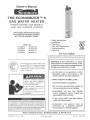
Owner's
Manual
THE ECONOM
GAS WATER
ERTM 6
HEATER
POWER VENTED GAS MODELS
WITH HOT SURFACE IGNITION
FOR POTABLE WATER HEATING ONLY.
NOT SUITABLE FOR SPACE HEATING.
NOT FOR USE IN MOBILE HOMES.
, Safety hstructions
mnstaHation
MODEL
153.332040
Operation
, Care and
NO.
40 Gallon
Nat
153.332050
50 Gallon
Nat
153.332060
40 Gallon
LP
153.332070
50 Gallon
LP
GA$-FmHEg
Maintenance
* Troubleshooting
, Parts List
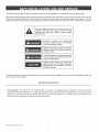
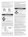
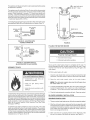
For Your Safety
AN ODORANT
C3 Technology _*Gas Water Heaters meet
the newANSI
Z21.10.1 standard that deals
with the
accidental
or unintended
of flammable
vapors,
emitted by gasoline,
such
ignition
as
IS ADDED TO THE GAS USED BY THIS WATER HEATER.
WARNING:
If the information
in these
instructions is not followed exactly, a fire
or explosion
may result causing property
damage, personal injury or death.
those
--Do
not store or use gasoline
or other
flammable
vapors
and liquids
in the
vicinity of this or any other appliance.
Read
and
understand
instruction
-- WHAT TO DO IF YOU SMELL GAS:
manual
and safety
messages
before
installing,
operating
or
servicing thiswater heater
• Do not try to Hght any appliance.
Failure
o Do not touch
to follow
instructions
safety messages
could
death or serious injury.
instruction
and
result
in
manual must remain with
water beater.
any emectricam switch;
• mmmediatemy caml your
gas suppmier
from a neighbor's
phone. Fommow the
gas eupplier'e
instructions,
o mfyou cannot
Si no puede leer o entender el ingles y necesita el manual instructivo
y/o etiquetas
en espa5oJ
puede
obtenerlos
Ilamando
al
1o800o821o2017. NO TRATE DE INSTALAR O OPERAR ESTE
CALENTADOR DEAGUAsi no entiende la infom_aci6n en las etiquetas
o en el manual instructivo. No hacer caso de esta advertencia podria
resultar en la MU ERTE O GRAVES LESIONES CORPORALES.
Sears,
PRINTED IN THE U.S.A. 0905
Roebuck
and Co., Hoffman
www.sears.com
do
not use any phone in your buimding.
reach your
camm
the fire department.
--Installation
and
service
gas suppmier,
must
be
performed
by a qualified
installer,
service agency orthe gas supplier.
Estates,
_L 60179 U.S.A
PART NO. 185249-000
Yoursafetyandthesafetyofothersis extremely
important
in the
installation,
use and servicLng
of tMs water
heater.
Many safetyore[ated
messages
and instructLons
have been provided
in this manual and on your own water heater to warn you and
others of a potential
injury hazard.
Read and obey all safety messages
and instructions
throughout
tMs manuaL,
mt is very
important
that the meaning
of each safety message
is understood
by you and others who instam[, use or service this water heater.
This is the safety
amert symbol
potential
persona[
injury
messages
that fommow this
injuryor
death.
m!!l[[I
_m!![[!l!
[t is used to alert you to
hazards.
symbom
Obey a[[ safety
to avoid
possibme
DANGER
indicates
an
imminently
hazardous
situation
which, if mot avoided_
could result in injuryor
death.
WARNING indicates a potentLaIIy hazardous
situation
which: if mot avoided, coumd result
in injury
CAUTION
or death.
indicates
a potentially
situafJon which, if not avoided,
minor or moderate injury.
hazardous
may resu[t in
CAUTION
used without
the safety
alert
symbom indicates
a potentiammy hazardous
situation
which, if mot avoided, could result
in propertydamage.
All safety messages will generally tell you about the type of hazard, what can happen if you do not follow the safety message and
how to avoid the risk of injury.
[MPORTANT DEF[NITIONS
Gas Supplier: The Natural Gas or Propane Utility or service who supplies gas for utilization by the gas burning
appliances within this application. The gas supplier typically has responsibility for the inspection and code approval of
gas piping up to and including the Natural Gas meter or Propane storage tank of a building. Many gas suppliers also
offer service and inspection of appliances within the building.
© Sears,
Roebuck
and
Co,
Readandunderstand
instruction
manualandsafetymessages
beforeinstalling,
operating
or
servicing
thiswater
heater.
Failure
to followinstructions
and
safetymessages
couldresultin
death
orserious
injury,
Instruction
manual
must
remain
with
water
heater.
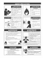
Water
(52°0)
temperature
can cause
instantly resulting
death.
over
severe
125°F
burns
Fire Hazard
For continued
riskoffire:
" Do not install
_' Do not operate
bathing
Temperature
available.
limiting
valves
Read
/,-
Fire or Explosion
)Iosion
Overheated
watertank
and
are
manual
for
safe
Hazard
Breathing
Hazard
vapors and
• Install vent system
• Do not operate
control
to excessive
sized
temperature
relief
valve
. _S,.,=% *
to combustibbs.
away from faucets
after extended
/
in accordance
Gas
with codes.
wafer heater if flood damaged,
water
, Do not place chemical
near wafer heater.
carbon
heater
air intake
vapor emitting
monoxide
detectors
are
with
manual before
installing, using or servicing
water heater.
improper
with
products
• No vent damper insfellation
is csmpagble
this power vented water heater.
Read instruction
for
if soot buildup.
, Do not obstruct
insulating jacket,
• Gas and
available.
period of nomuse.
iVionoxide
• High altitude
orifice must be installed
operation above 7,700 feet (2,347 rn).
gas
on rating plate.
Keep ignition sources
water can cause
explosion.
pressure
- Carbon
- Do not operate
" Maintain required clearances
Hazard
provided.
pressure,
Use onlygasshown
if
setting.
,, Avoid all ignition sources if you smell LP gas
heater
heater
or
liquids in the vicinity of this or any other appliance.
water
water
must be inatalled in opening
Do not store or use gasoline or other flammable
'_ Do not expose
on
-,,
,, Propedy
instruction
temperature
heater
flood damaged.
Children,
the elderly,
and the
physically or mentally disabled are at
highest risk for scald injury.
before
water
against
carpeted floor.
in severe injury or
Feel
water
showering.
protection
Breathing carbon monoxide can cause brain damage or death
Always read and understand instruction manual.
ies_llation
and use may result
in property damage.
, Betore servicing the water heater, make sure the bio_e_
assembly is unplugged or the electrical supply to the
wafer heater is turned "OFF".
Do not operate water heater ftftood damaged.
Inspect and replace anode.
Install in location with drainage,
Fill tank with water before operation,
Be alert for thermal expansion.
Refer to instruction manual for installation
operation Ver_y proper opera,on after servicing
and seance.
' Failure to do this could resu_ in death, serious bodi_]
injury, or property damage.
SAFEINSTALLATION,
USEAND
SERVICE
.......................................................................................................................
2
SAFETY
PRECAUTIONS
.............................................................................................................................................
3
TABLE
OFCONTENTS
...............................................................................................................................................
4
CUSTOMER
RESPONSIBILITIES
..................................................................................................................................
5
PRODUCT
SPECIFICATIONS
.......................................................................................................................................
5
MATERIALS
ANDBASIC
TOOLS
NEEDED
.......................................................................................................................
6
TYPICAL
INSTALLATION
..............................................................................................................................................
7
INSTALLATION
INSTRUCTIONS
...................................................................................................................................
8=21
Removing
theOldWaterHeater..............................................................................................................................
8
Factsto Consider
AbouttheLocation
.......................................................................................................................
9=10
InsulationBlankets
..............................................................................................................................................
10
Combustion
Air andVentilation
forAppliances
Locatedin Unconfined
Spaces
.............................................................
10
Combustion
Air andVentilation
forAppliances
Locatedin Confined
Spaces............................................................
10=11
WaterPiping......................................................................................................................................................
12-13
Temperature=Pressure
ReliefValve.........................................................................................................................
13-14
GasPiping.........................................................................................................................................................
14-15
Sediment
Traps..................................................................................................................................................
15
FillingtheWaterHeater........................................................................................................................................
15
BlowerAssemblyInstallation
..................................................................................................................................
15-16
VentConnections
to BlowerAssembly
......................................................................................................................
17
VentingandInstallation
........................................................................................................................................
17
Condensation
....................................................................................................................................................
17
Maximum
VentLengths
.........................................................................................................................................
17
Venting.............................................................................................................................................................
18
VentTerminalInstallation
......................................................................................................................................
18-19
Vertical
VentThrough
Roof.....................................................................................................................................
19
VerticalVentTermination
Restrictions
.......................................................................................................................
19
VentPipePreparation
...........................................................................................................................................
20-21
OPERATING
INSTRUCTIONS
.......................................................................................................................................
22-23
LightingandOperating
Label.................................................................................................................................
Temperature
Regulation
........................................................................................................................................
23
FORYOUR
INFORMATION
...........................................................................................................................................
24-25
StartUpConditions
..............................................................................................................................................
24-25
Operational
Conditions
.........................................................................................................................................
25
SERVICE
ANDADJUSTMENT
.......................................................................................................................................
25-27
VentingSystemInspection
.....................................................................................................................................
25
BurnerOperation
andInspection
............................................................................................................................
25-26
BurnerCleaning.................................................................................................................................................
26
Housekeeping
....................................................................................................................................................
26
AnodeRodInspection
...........................................................................................................................................
26
Temperature-Pressure
ReliefValveOperation
............................................................................................................
26-27
Draining............................................................................................................................................................
27
DrainValveWasherReplacement
............................................................................................................................
27
Service.............................................................................................................................................................
27
LEAKAGE
CHECKPOINTS
...........................................................................................................................................
28
TROUBLESHOOTING
GUIDELINES
...............................................................................................................................
29-30
REPAIR
PARTS
LIST..................................................................................................................................................
31
WARRANTY
.............................................................................................................................................................
32
Thank
Youforpurchasing
aKenmore
water
heater.
Properly
installed
andmaintained,
itshould
giveyouyears
oftrouble
freeservice,
ifyou
should
decide
thatyouwantthenewwaterheater
professionally
installed
bySears
call1-8004-M%HOME®.
They
\,viii
arrange
forprompt,
quality
installation
bySears
authorized
contractors.
Abbreviations
Found
InThisInstruction
Manual:
CSA-Canadian
Standards
Association
ANSI
-American National Standards institute
3. The water heater when installed must be grounded in accordance
with the local codes, or in the absence of local codes, the National
Electrical Code NFPA 70.
NFPA- National Fire Protection Association
ASME - American Society of Mechanical Engineers
GAMA - Gas Appliance Manufacturer's Association
UL - Underwriters Laboratories Inc.
4.
• CSA4.!
If after reading this manual you have any questions or do not
understand any portion of the instructions, call the local gas utility or
the Sears Service Center.
Carefully plan the place where you are going to put the water heater.
Correct combustion, vent action, and vent pipe installation are very
important in preventing death from possible carbon monoxide
poisoning and fires.
This gas-fired water heater is listed by Underwriters Laboratories Inc.
underAmerican National Standard/CSA Standard for Gas Water Heaters
ANSI Z21.10.1
The installation must conform with these instructions and the Ioca!
code authority having iurisdiction. In the absence of local codes,
installations shall comply with the National Fuel Gas COdeANSI Z223.1/
NFPA54 and the National Electrical Code, NFPA70. These publications
are available from The National Fire Protection Association,
1
Battery, march Park, Quincy, MA 02269.
(current edition).
PREPARING FOR THE INSTALLATION
Examine the location to ensure the water heater complies with the
"Facts to ConsiderAbout
the Location" section in this manual.
Read the "Safety Precautions" section, page 3 of this manual first
and then the entire manual carefully. If you don't follow the safety
For California installation this water heater must be braced, anchored,
or strapped to avoid falling or moving during an earthquake.
See
instructions for correct installation procedures. Instructions may be
obtained from California Office of the State Architect, 400 P Street,
Sacramento, CA 95814.
rules, the water heater will not operate properly.
It could cause
DEATH, SERIOUS BODILY INJURYAND/OR PROPERTY DAMAGE.
This manual contains instructions for the installation, operation, and
maintenance of the gas4ired water heater. It also contains warnings
throughout
the manual
7.
that you must read and be aware of. All
warnings and all instructions are essential to the proper operation
of the water heater and your safety. Since we cannot put eveQ/thing
on the first few pages, READ THE ENTIRE MANUAL BEFORE
ATTEMPTING TO INSTALL OR OPERATE THE WATER HEATER.
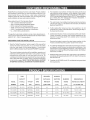
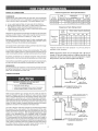
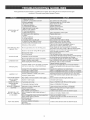
TANK
CAPACITY
Massachusetts
Code requires this water heater to be installed in
accordance with Massachusetts 248-CMR 2.00: State Plumbing Code
and 248-CMR 5.00.
8. CompiieswithSCAQMDrule#1121
NOx requirements.
RECOVERY
MINIMUM
INPUT
RATE GALS.
VENT PRPE
DBA_,_ETER
and distdcts having equivalent
DIMENSBONS IN
MODEL
IN GALS.
TYPE OF
RATE
PERHOUR
INCHES
iNCHES
NUMBER
(LTRS)
GAS
(Btuthr)
@90°F R_SE
(ram)
(ram)
153.332040
40 (151)
NATURAL
40,000
44
2 (51)
18 1/2 (470)
55 (1,397)
153.332050
50 (169)
NATURAL
40,000
44
2 (51)
20 (508)
56 3/4 (1,441)
153.332060
40 (151)
PROPANE
40,000
44
2 (51)
18 1/2 (470)
55 (1,397)
153.332070
50 (16e)
PROPANE
40,000
44
2 (51)
20 (508)
56 3/4 (1,441)
iNCHES (ram} NERGHT
TO JACKET
TOP
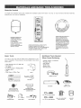
Materials
Needed
To simplify
the installation
depending
on your type
Sears
has available
the installation
parts shown
below.
You may
or may not need
al! of these
materials,
of installation.
_'_"'111'I
_,_1
_'_11_
DRA_N PANS AVAILABLE
EXPANSION TANKS FOR
THERMAL EXPANSION
CONDITIONS AVAILABLE
iN 2 GALLONS
(7.8 LITERS} AND
5 GALLONS (18.9 LITERS)
CAPACITY THROUGH
LOCAL SEARS STORE OR
SERVICE CENTER.
A DIAMETER 22" (559 ram) OR
LESS AND AVAILABLE IN 28"
(711 rnm} DIAMETER FOR
WATER HEATERS HAVING A
DIAMETER 28" (650 ram) OR
LESS.
WATER HEATER INSTALLATION KIT WITH
FLEXIBLE CONNECTORS
FOR 8/4"
(19.05 ram} OR 1/2" (12.7 ram) THREADED OR
COPPER PLUMBING AND FLEXIBLE GAS
CONNECTOR WITH FITTINGS.
Basic
Too_s
Additional
You may or may not need all these tools, depending
on your
type of installation.
These tools can be purchased
at your local
Sears Store.
Pipe Wrenches
Screwdriver
(2) 14" (356 ram)
Tools Needed
When Sweat
Tubing Cutters
Propane
Tank
Soft Solder
Solder F_ux
Soldering
or Hacksaw
Emery C_oth
Wire Brushes
Tin Snips
8' (1.82 m) Tape or Fo_ding Ruler
Garden Hose
DriH
Pipe Dope or Teflon
Tape
DRILL
TUBING
SLOT-HEAD
iN 20"
(508 ram} DIAMETER FOR
WATER HEATERS HAVING A
DIAMETER 18" (457 ram) OR
LESS, 24" (810ram) DIAMETER
FOR WATER HEATERS HAVING
CUTTER
PROPANE
TORCH
SCREWDRIVER
TiN SNIPS
PHILLIPS
SCREWDRIVER
HACKSAW
ROLL OF
EMERYCLOTH
P{PE DOPE
ROLL OF TEFLON
TAPE (USE ONLY ON
WATER CONNECTIONS)
(SQUEEZE TUBE)
USE FOR WATER AND GAS
CONNECTIONS
8/4" (19 ram) WiRE BRUSH
GARDEN
HOSE
8 FOOT TAPE
PIPE
WRENCH
1/2" (13 ram) WiRE BRUSH
ROLL OF LEAD-FREE
SOFTSOLDER
SOLDER
FLUX
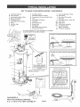
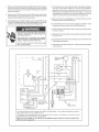
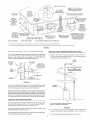
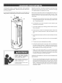
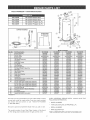
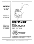
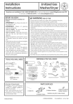
GET TO KNOW YOUR WATER
K
Hot Water
L
Outlet
M
N
Temperature-Pressure
Flue
O
P
Hue Baffte
mnsulation
Union
Q
Control
runlet Dip Tube
Anode**
R
S
T
U
Rating Plate
Gas Suppmy
Manua{ Gas Shut-off
Ground
Joint Union
A
B
Vent Pipe=Exhaust
Vent Terminal
C
D
E
F
Vent Adapter-Rubber
Blower
Assembly
CoJd Water Inlet
runlet Water Shut-off
G
H
J
Boot
Valve
* ALL
P}P}NG
** LOCATED
MATERIALS
UNDER
THE
HEATER
- GAS MODELS
Outlet
Receptacle
(115 VAC)
Relief
Valve
Assembly**
Harness
Drip Leg (Sediment
DrainValve
X
Y
Gas Valve-Thermostat
Drain Pan
Trap)
Z
AA
Air mntake Screen
runner Door
BB
Outer
CC
DD
HSl Burner
Assembly
Air intake Screen o
EE
Blower
Assembly
FV Sensor Assembly
Valve
TO BE SUPPLIED
BLOWER
V
W
o Base
Pan
Door
BY CUSTOMERS.
ASSEMBLY.
NATURAL HOT SURFACE IGNITER & MABN BURNER
NOT
SURFACE
*INSTALL
PER
LOCAL CODES.
PROPANE
HOT SURFACE
IGNITER
& MAIN
BURNER
NOT
EURFACE
INSTALL THERMAL
EXPANSUON
TANK UFWATER HEATER iS
UNSTALLED
IN A CLOSED WATER
SYSTEM
*CAUTION:
115 VAC IN CONTROL
AND INSIDE OUTL=R DOOR
HARNESS
J
TEMPERATURE
INDICATORS
OUTER DOOR
(ALTERNATE)
EE
GAS MODELS
WiTH HOT SURFACE
i
_GN_T_ON
& 2", 3 °' OR 4" PVC VENT CAPAB_UTY
FIGURE1,
7
CC
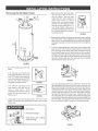
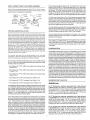
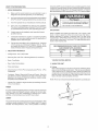
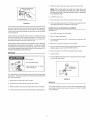
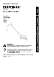
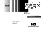
Removing
the Old Water
Heater
4. Attach a hose to the water heater drain
valve and put the other end in a floor
®
drain or outdoors.
Open the water
heater drain valve. Open a nearby hot
water
faucet
which
will relieve
pressure in the water heater and speed
draining.
The water passing out of the
drain valve may be extremely hot. To
avoid being scalded, make sure all
connections are tight and that the water
flow is directed away from any person,
see Figures 2 and 5.
FmGURE5.
Disconnect the vent pipe from the blower assembly where it connects
to the water heater. In most installations the vent pipe can be lifted off
after any screw or other attached devices are removed. Make sure
existing vent complies with maximum and minimum vent lengths on
page 17.
If you have copper piping to the water heater, the two copper water
pipes can be cut with a hacksaw approximately four inches away
from where they connect to the water heater, see Figure 6. This will
avoid cutting off pipes too short. Additional
cuts can be made later if
necessary. Disconnect the temperature-pressure
line. When the water heater is drained, disconnect
relief valve drain
the hose from the
drain valve. Close the drain valve. The water heater is now completely
disconnected and ready to be removed.
FIGURE2.
1. Turn "OFF" the gas supply to the water
heater.
If the main gas line Shut-off
serving all gas appliances
valve
is used, also
shut "OFF" the gas at each appliance.
I
Leave all gas appliances shut "OFF"
until the water heater installation is
completed,
2.
RGURE 6.
F_GURE3.
see Figures 2 and 3.
If you have galvanized pipes to the water heater, loosen the two
galvanized pipes with a pipe wrench at the union in each line. Also
disconnect the piping remaining to the water heater, see Figure 7.
Turn "OFF" the water supply to the
water heater at the water shut off
valve
or
installations
turned
water
meter.
These pieces should be saved since they may be needed when
reconnecting the new water heater. Disconnect the temperature°
pressure relief valve drain line. When the water heater is drained,
disconnect the hose from the drain valve. Close the drain valve.
Some
require that the water be
off to the entire
house,
see
Figures 2 and 4.
RGURE4.
3. Check again to make sure the gas supply is "OFF" to the water
heater. Then disconnect the gas supply connection from the gas
control valve.
The water heater is now completely disconnected and ready to be
removed. Mineral buildup or sediment may have accumulated in the
old water heater. This causes the water heater to be much heavier
than normal and this residue,
if spilled out, could cause staining.
Burn hazard
, Hot water discharge.
• Keep hands clear of drain
RGURE 7.
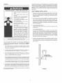
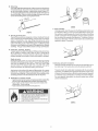
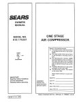
FACTS TO CONSIDER ABOUT THE LOCATION
Carefully choose an indoor location for the new water heater, because
the placement is a very important consideration for the safety of the
occupants in the building and for the most economical use of the appliance.
This water heater is not for use in manufactured
(mobile) homes
or outdoor installation.
AIR BNTAKE
SCREEN
FVSENSOR
ASSEIVnIBLY
FIGURE&
Whether replacing an old water heater or putting the water heater in a
new location, the following critical points must be observed:
1. Select a location indoors as close as practical to the vent terminal or
location to which the water heater vent piping is going to be connected,
and as centralized with the water piping system as possible.
2. Selected location must provide adequate clearances for servicing
Fire or Explosion
and proper operation of the water heater.
Hazard
Do not store or use gasoline or other flammable vapors and
liquids in the vicinity of this or any other appliance.
Avoid all ignition sources if you smell LP gas.
Property
Damage
Do not expose
Hazard
water
heater
control to excessive
gas
pressure.
All water heaters eventually lea k.
_' Use only gas shown on rating plate
Do not install without adequate drainage.
'_ Keep ignition sources
Maintain required cleara nces to combustibles
,
away from faucets after extended
period of nomuse.
/
Installation of the water heater must be accomplished in such a manner
that if the tank or any connections should leak, the flow will not cause
damage to the structure. For this reason, it is not advisable to install the
water heater in an attic or upper floor. When such locations cannot be
avoided, a suitable drain pan should be installed under the water heater.
Drain pans are available at your local hardware store. Such a drain pan
must have a minimum length and width of at least 2" (5.1 cm) greater than
the water heater dimensions and must be piped to an adequate drain.
The pan must not restrict combustion air flow.
Read instruction
manual before
installing, using or servicing
water heater.
Also, the water heater must be located
and/or protected
so it is not
subiect to physical damage by a moving vehicle.
Water heater life depends upon water quality, water pressure and the
environment in which the water heater is installed. Water heaters are
sometimes installed in locations where leakage may resuJt in property
damage, even with the use of a drain pan piped to a drain. However,
unanticipated damage can be reduced or prevented by a leak detector or
water shut-off device used in conjunction with a piped drain pan. These
devices are available from some plumbing supply wholesalers and
retailers, and detect and react to leakage in various ways:
Fire Hazard
For continued
riskoffire:
protection
Do not install
against
water heater
on
carpeted floor.
• Sensors mounted in the drain pan that trigger an alarm or turn offthe
incoming water to the water heater when leakage is detected.
Do not operate
water heater
if
flood damaged.
• Sensors mounted in the drain pan that turn off the water supply to the
entire home when water is detected in the drain pan.
* Water supply shut-off devices that activate based on the water
pressure differential between the cold water and hot water pipes
connected to the water heater.
This water heater must not be installed directly on carpeting.
• Devices that will turn off the gas supply to a gas water heater while at
the same time shutting off its water supply.
entire floor must be covered by the panel.
Carpeting
must be protected by metal or wood panel beneath the appliance extending
beyond the full width and depth of the appliance by at least 3" (7.6 cm) in
any direction, or if the appliance is installed in an alcove or closet, the
Failure to heed this warning
may result in a fire hazard.
INSTALLATIONS IN AREAS WHERE FLAMMABLE LIQUIDS (VAPORS)
ARE LIKELYTO BE PRESENT OR STORED (GARAGES, STORAGEAND
UTtLITYAREAS,
ETC.): Flammable liquids (such as gasoline, solvents,
propane (LP or butane, etc.) and other substances (such as adhesives,
etc.) emit flammable vapors which can be ignited by a gas water heater's
hot surface igniter or main burner. The resulting flashback and fire can
cause death or serious burns to anyone in the area. This water heater is
equipped with a FV sensor for detecting the presence of flammable
vapors, see Figure 8. When the sensor detects those vapors, the unit
will shut down and not operate. Should this happen, please refer to the
troubleshooting guide on pages 29°30. Even though this water heater is
a flammable vapors ignition resistant water heater and is designed to
reduce the chances of flammable vapors being ignited, gasoline and
other flammable substances should never be stored or used in the same
Fire or Explosion
Hazard
Read instruction manual before [nstaNing,
using or servicing water heater
Improper use may result in fire or
explosion.
Maintain required
combustibles.
Minimum
vicinity or area containing a gas water heater or other open flame or
spark producing appliance.
construction
9
clearances
between
clearances
the water
heater
to
and combustible
are 0 inch at the sides and rear, 5" (12.7 cm) from the front
and12"(30.5cm)fromthetop.(Standard
clearance.)
Ifclearances flammable
inmany
cases,
will also react to form corrosive hydrochloric
stated
ontheheater
differ
from
standard
clearances,
instal
water
heater acid when exposed to the combustion products of the water heater.
The results can be hazardous, and also cause product failure.
according
toclearances
stated
ontheheater.
Adequate
clearance
forservicing
thisappliance
should
beconsidered INSULATION BLANKETS
before
installation,
such
aschanging
theanodes,
etc.
Insulation blankets are available to the general public for external use
on gas water heaters but are not necessary with Kenmore products.
Aminimum
clearance
of5"(!2.7cm)mustbea/owed
foraccess
to
replaceable
parts
such
asthethermostats,
drain
valve
andrelief
valve. The purpose of an insulation blanket is to reduce the standby heat loss
encountered with storage tank heaters. Your Kenmore water heater
When
installing
theheater,
consideration
must
begiven
toproper
location. meets or exceeds the National Appliance Energy Conservation Act
Location
selected
should
beasclose
tothewa/aspracticable
andas
standards with respect to insulation and standby loss requirements,
making an insulation blanket unnecessary.
centralized
withthewater
piping
system
aspossible.
Breathing
Hazard - Carbon
Monoxide
Gas
Do not obstruct water heater air intake
with insulating blanket.
Gas and carbon monoxide
are avalable.
I I 0" IIIN.
detectors
Instal water heater in accordance with
the instruction manual.
FIGURE!.
Breathing carbon monoxide can cause brain damage or
death. Always read and understand instruction manual.
Breathing
Hazard - Carbon
Monoxide
Gas
Should you choose to apply an insulation blanket to this heater, you
should follow these instructions
(For identification
of components
mentioned below, see Figure 1). Fa/ure to fo/ow these instructions
can restrict the air flow required for proper combustion,
potentially
resulting in fire, asphyxiation, serious personal injury or death.
Install water heater in accordance with
the instruction manual and NFPA54.
_.,,_
To avoid
ventilation
_
injury, combustion
air must be taken
and
from
Do not apply insulation to the top of the water heater, as this will
interfere with safe operation of the blower assembly.
Do not cover the outer door, thermostat or temperature & pressure
relief valve.
outdoor°
• Do not place chemical vapor emitting
products near water heater
Do not a/ow insulation to come within 2" (5.1 cm) of the floor to
prevent blockage of combustion air flow to the burner.
Do not cover the instruction manual.
Keep it on the side of the
water heater or nearby for future reference.
D__.£obtain new warning
and instruction
labels from Sears
for placement on the blanket directly over the existing labels.
D__£inspect the insulation blanket frequently
to make certain it
does not sag, thereby obstructing combustion air flow.
Breathing carbon monoxide can cause brain damage or
death. Always read and understand instruction manual.
A gas water heater cannot operate properly without the correct amount
of air for combustion. Do not install in a confined area such as a closet,
unless you provide air as shown in the "Facts to Consider About the
Location" section.
Never obstruct the flow of ventilation air. If you
have any doubts or questions at all, call your gas supplier. Failure to
provide the proper amount of combustion air can result in a fire or
explosion and cause death, serious bodily injury, or property damage.
COMBUSTION AIR AND VENTILAT_ON FOR
APPLIANCES LOCATED IN UNCONFINED SPACES
UNCONFINED
SPACE is space whose volume is not less than
50 cubic feet per 1,000 Btu per hour (4.8 cubic meters per kW) of the
aggregate input rating of a/appliances
installed in that space. Rooms
communicating
directly with the space in which the appliances
are
insta/ed, through openings not furnished with doors, are considered a
part of the unconfined space.
t2" MAX.-(80,5
cm} -VI_NTILATION
AIR
-F RONT
OF
DUCT
In unconfined spaces in buildings, infiltration may be adequate to provide
air for combustion, ventilation and dilution of flue gases. However, in
buildings of tight construction (for example, weather stripping, heavily
insulated, caulked, vapor barrier, etc.), additional air may need to be
provided using the methods described in "Combustion Air and Ventlation
forAppliances
Located in Confined Spaces."
12" MAX.
(30.5 era)
VIEW
DOOR
FIGURE 10.
COMBUSTION AIR AND VENTILATION FOR
APPLIANCES LOCATED IN CONFINED SPACES
If this water heater will be used in beauty shops, barber shops, cleaning
establishments, or self-service laundries with dry cleaning equipment,
it is imperative that the water heater or water heaters be installed so
that combustion and ventilation air be taken from outside these areas.
CONFINED
Prope/ants
of aerosol sprays and volatile compounds,
(cleaners,
chlorine based chemicals, refrigerants, etc.) in addition to being highly
SPACE is a space whose volume is less than 50 cubic feet
per 1,000 Btu per hour (4.8 cubic meters per kW) of the aggregate
input rating of all appliances installed in that space.
10
Chemical
vapor
corrosion
oftheflue,blower
assembly
andventsystem
mayoccurifairforcombustion
contains
certain
chemical
vapors.
Spray
canpropellants,
cleaning
soJvents,
refrigerator
andairconditioner
refrigerants,
swimming
poolchemicals,
calcium
andsodium
chloride,
waxes,
bleach
andprocess
chemicals
aretypical
compounds
which
arepotentially
corrosive.
2.
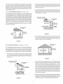
When communicating with the outdoors through vertical ducts, each
opening shall have a minimum free area of 1 square inch per 4,000
Btu per hour (5.5 cm2/kW) of total input rating of all equipment in the
enclosure,
see Figure 13.
When communicating
with the outdoors through horizontal ducts,
each opening shall have a minimum free area of 1 square inch per
A.ALLAmR
FROM
INSBDE
BUILDINGS:
(See
Figure
10and11)
Theconfined
space
shaJl
beprovided
withtwopermanent
openings
communicating
directly
withanadditional
room(s)
ofsufficient
volume
sothatthecombined
voJume
ofallspaces
meets
thecriteria
foran
unconfined
space.
Thetotalinput
ofallgasutiJization
equipment
installed
inthecombined
space
shall
beconsidered
inmaking
thisdetermination.
Each
opening
shallhave
aminimum
freearea
ofonesquare
inchper
1,000
Btuperhour
(22cm2/kW)
ofthetotal
input
rating
ofallgasutilization
equipment
intheconfined
space,
butnotlessthan100square
inches
(645cm2).Oneopeningshallcommence
within!2 inches
(31cm)ofthetopandonecommencing
within
12inches
(31cm)ofthe
bottom
oftheenclosures.
2,000 Btu per hour (11 cm2/kW)) of total input rating of all equipment
in the enclosure, see Figure 14.
VENTILATION LOUVERS
(each end of attic)'_
VENT THROUGH
i
AIR OUTLET f_tt
_ VE_,JTTO
lllp 4T
INLETAIRDUDT_"_JII
(ends 1" above floor} _
VENT THROUGH
_ ROOF
J
_
Jl
WATER
HEATER
OUTDOORS
OPE_'JING_i
FIGURE 13.
HEATER
WATER
kJ
4. When ducts are used, they shall be of the same cross-sectional
area as the free area of the openings to which they connect. The
minimum short side dimension of rectangular
less than 3 inches (7.6 cm), see Figure 14.
air ducts shall not be
FIGURE 11.
B. ALL AiR FROM OUTDOORS:
(See Figures 12, 13 and 14)
The confined space shall be provided with two permanent openings,
one commencing
within !2 inches (31 cm) of the top and one
commencing within !2 inches (3! cm) from the bottom of the enclosure.
The openings shall communicate directly, or by ducts, with the outdoors
or spaces (crawl or attic) that freely communicate
with the outdoors.
1. When directly communicating with the outdoors, each opening shall
have a minimum free area of 1 square inch per 4,000 Btu per hour
(5.5 cm2/kW) of total input rating of all equipment
see Figure 12.
in the enclosure,
FIGURE 14.
VENTILATION
LOUVERS
(each end of attic
Louvers and Grilles: in calculating free area, consideration shalJ be
given to the blocking effect of louvers, griJles or screens protecting
openings.
Screens used shall not be smaller than 1/4 inch
(6.4 mm) mesh. if the free area through a design of louver or grille
VENT THROUGH
_. ROOF
is known, it should be used in calculating the size opening required
to provide the free area specified, if the design and free area is not
known, it may be assumed that wood louvers will be 20_25 percent
free area and metal louvers and grilles will have 60-75 percent free
area. Louvers and grilles shall be fixed in the open position or
VENTTO
OUTDOORS
interlocked with the equipment so that they are opened automatically
during equipment operation.
VENTILATION LOUVERS
6.
Special Conditions Created by Mechanical Exhausting or Fireplaces:
operation of exhaust fans, ventilation systems, clothes dryers or
fireplaces may create conditions requiring special attention to avoid
unsatisfactory operation of installed gas utilization equipment.
HGURE12.
11
WATER PIPING
Toxic chemicals, such as those used for boiler treatment
introduced into this system.
When the system requires water at temperatures
higher than required
for domestic water purposes, a tempering valve must be installed. Please
refer to Figure 15 for suggested piping arrangement.
Water
temperature
over 125°F
(52°C)
can cause severe burns
instantly resulting in severe iniury or
death.
Water supply systems may, because of such events as high line
pressure, frequent cut-offs, the effects of water hammer among others,
Children,
the elderly,
and the
physically or mentally disabled are at
highest risk for scald injury.
Feel water
showering.
before
bathing
Temperature
available.
limiting
valves
Read
temperature
HOTTER
have installed devices such as pressure reducing valves, check valves,
back flow preventers, etc. to control these types of problems. When
these devices are not equipped with an internal by-pass, and no other
measures are taken, the devices cause the water system to be closed.
As water is heated, it expands (thermal expansion) and closed systems
or
are
do not allow for the expansion
instruction
manual
of heated water.
for safe
setting.
The water within the water heater tank expands as it is heated and
increases the pressure of the water system. If the relieving point of the
water heater's temperature-pressure
relief valve is reached, the valve
WATER CAN SCALD:
will relieve the excess pressure.
The temperature-pressure
valve
is not intended
for the constant
relief
of
Water heaters are intended to produce hot water. Water heated to a
temperature which will satisfy space heating, clothes washing, dish
washing, cleaning and other sanitizing needs can scald and permanently
injure you upon contact. Some people are more likely to be permanently
relief
thermal
expansion.
This is an unacceptable condition and must be corrected.
It is recommended that any devices installed which could create a closed
system have a by-pass and/or the system have an expansion tank to
relieve the pressure built by thermal expansion in the water system.
Thermal expansion tanks are available from Sears stores and through
the Sears Service Centers. Contact the local plumbing inspector, water
supplier and/or the Sears Service Center for assistance in controlling
these situations.
injured by hot water than others. These include the elderly, children, the
infirm, or physically/mentally
handicapped.
If anyone using hot water in
your home fits into one of these groups or if there is a local code or state
law requiring a certain temperature water at the hot water tap, then you
must take special precautions.
In addition to using the lowest possible
temperature setting that satisfies your hot water needs, a means such
as a *mixing valve, shall be used at the hot water taps used by these
people or at the water heater, see Figure 15. Valves for reducing point
of use temperature by mixing cold and hot water are also available:
NOTE: To protect
against untimely
corrosion
of hot and cold
water fittings,
it is strongly
recommended
that di-electric
unions
or couplings
be installed
on this water heater when connected
to copper
HOT WATER
shall not be
pipe.
COLD WATER
OUTLET
Property
. Avoid water
÷
*MIXIN_
VALVE
WATERHEATER
. Do not apply
Contact
FIGURE 15.
Consult Sears Service Center.
heater
, Install thermal
FROM
HOT WATER
OUTLET ON
WATER HEATER
Follow manufacturer's
instructions
Damage
Hazard
damage.
expansion
tank if necessary
heat to cold water
qualified
installer
inlet.
or Sears Service
Center.
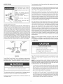
Figure !6 shows the typical attachment of the water piping to the water
heater.
The water heater is equipped
with 3/4 inch NPT water
connections.
for
installation of the valves. Before changing the factory setting on the
thermostat, read the "Temperature Regulation" section in this manual.
NOTE: ff using
copper
tubing,
solder
tubing
to an adapter
before
attaching
the adapter to the cold water inlet connection.
Do not
solder the cold water supply line directly to the cold water inlet.
It will harm the dip tube and damage the tank.
Toxic
- Do not connect
Chemical
to non=potable
,dater system.
This water heater shall not be connected to any heating system
component or used as a nompotable water heating appliance.
All piping components
with potable water.
connected
Look at the top cover of the water heater. The water outlet is marked
"HOT". Put two or three turns of teflon tape around the threaded end
of the threaded-to-sweat
coupling and around both ends of the 3/4"
NPT threaded nipple. Using flexible connectors, connect the hot water
pipe to the hot water outlet on the water heater.
Hazard
Look at the top of the water heater. The cold water inlet is marked
"COLD". Put two or three turns of teflon tape around the threaded
end of the threaded-to-sweat
coupling and around both ends of the
3/4" NPT threaded nipple. Using flexible connectors, connect the cold
or
to this unit shall be suitable for use
water pipe to the cold water inlet of the water heater.
12
INSTALLATION COMPLETED USING INSTALLATION KiT
HOT WATER
OUTLET
FLEXIBLE
WATER
TEMPERATURE-PRESSURE
RELIEF VALVE
COLOWATER
INLET
CONNECTORS
E×piosion
Hazard
VALVE
SHUTOFF
l
Temperature@ressure
THREADED
TO
SWEATCOUPLING
relief valve
must comply with ANSI Z21<22CSA 4.4 and ASME code.
Propedy sized ternperature-relief
valve must be installed in opening
provided
Can
result
in overheating
and
excessive tank pressure.
TEMPERATURE°
_--_PRESSURE
RELIEF VALVE
Can cause serious injury or death
This heater is provided
with a properly
certified
temperature - pressure relief valve by the manufacturer.
combination
The valve is certified by a nationally recognized testing laboratory that
maintains periodic inspection of production
of listed equipment
of
materials as meeting the requirements for Relief Valves and Automatic
Gas Shut-off Devices for Hot Water Supply Systems,ANSI Z21.22 • CSA
4.4, and the code requirements of ASME.
DISCNARGEPPE
(DO NOT CAP OR PLUG]
If replaced, the valve must meet the requirements of local codes, but not
less than a combination temperature and pressure relief valve certified
as indicated in the above paragraph.
DRAIN
PAN
The valve must be marked
the marked
hydrostatic
(150 psi = 1,035 kPa) and
heater input rate as shown
FIGURE1&
T & P Valve and Pipe Insulation
(if supplied)
Remove insulation for T & P valve and pipe connections
For safe operation of the water heater, the relief valve must not be
removed from its designated opening nor plugged.
from carton.
The temperature@ressure
relief valve must be installed directly into the
fitting of the water heater designed for the relief valve. Position the valve
downward and provide tubing so that any discharge will exit only within
6 inches (! 5.2 cm) above, or at any distance below the structural floor.
Be certain that no contact is made with any live electrical part. The
discharge opening must not be blocked or reduced in size under any
circumstances.
Excessive length, over 30 feet (9.14 m), or use of more
than four elbows can cause restriction
and reduce the discharge
capacity of the valve, see Figures 16 or 20.
INSULATED
INLET
INSULATED
with a maximum set pressure not to exceed
working
pressure
of the water heater
a discharge capacity not less than the water
on the model rating plate.
No valve or other obstruction is to be placed between the relief valve
and the tank. Do not connect tubing directly to discharge drain unless a
6"(15.2 cm) air gap is provided. To prevent bodily injury, hazard to life,
or property damage, the relief valve must be allowed to discharge water
in quantities should circumstances demand. If the discharge pipe is not
connected to a drain or other suitable means, the water flow may cause
property damage.
FIGURE17.
Fit pipe insulation over the incoming cold water line and the hot water
line. Make sure that the insulation is against the top cover of the heater.
Fit T & P valve insulation over valve. Make sure that the insulation
not interfere with the lever of the T & P valve.
Water Damage
does
Hazard
Temperature-pressure
relief valve discharge
pipe must terminate at adequate drain
Secure all insulation using tape.
13
TheDischarge
Pipe:
•Shall
notbesmaller
insizethantheoutlet
pipesizeofthevalve,
or
have
anyreducing
couplings
orother
restrictions.
•Shall
notbeplugged
orblocked.
•Shallbeofmaterial
listed
forhotwater
distribution.
•Shallbeinstalled
soastoallowcomplete
drainage
ofboththe
temperature-pressure
relief
valve,
andthedischarge
pipe.
•Shall
terminate
atanadequate
drain.
•Shallnothave
anyvalve
between
therelief
valve
andtank.
If the main gas line Shut-off serving
turn "off" the gas at each appliance.
"off" until the water heater installation
all gas appliances
is used, also
Leave all gas appliances shut
is complete.
A gas line of sufficient size must be run to the water heater. Consult
the current edition of National Fuel Gas Code ANSI Z223.1/NFPA54 and
your gas supplier concerning
pipe size.
There must be:
• A readily accessible manual shut off valve in the gas supply line
serving the water heater, and
• A drip leg (sediment trap) ahead of the gas control valve to help
Watertemperature
over 125°F
(52°C)cancausesevereburns
instantly
resulting
insevere
injury
or
death_
Children,
the elderly,and the
physically
ormentally
disabled
areat
highest
riskforscald
iniury.
Feelwaterbeforebathingor
showering,
Temperature
limitingvalvesare
available.
Readinstruction
manual
for safe
temperature
setting.
prevent dirt and foreign materials from entering the gas control valve.
• A flexible gas connector or a ground joint union between the shut off
valve and control valve to permit servicing of the unit.
Be sure to check all the gas piping for leaks before lighting the water
heater. Use a soapy water solution, not a match or open flame. Rinse
off soapy solution and wipe dry.
Breathing
Thetemperature-pressure
relief
valve
must
bemanually
operated
atleast
once
ayear.Caution
should
betaken
toensure
that(1)nooneisinfront
oforaround
theoutlet
ofthetemperature-pressure
relief
valve
discharge
line,
and(2)thewater
manually
discharged
willnotcause
anybodily
injury
orproperty
damage
because
thewater
maybeextremely
hot.
Ifaftermanually
operating
thevalve,
itfailstocompletely
resetand
continues
torelease
water,
immediately
close
thecoldwater
inletto
thewaterheater,
followthedraining
instructions,
andreplace
the
temperature-pressure
relief
valve
withanewone.
Hazard - Carbon
Monoxide
Gas
High altitude orifice must be installed
for operation above 7,700 ft (2,347 m)
'_ Contact a qualified installer or service
agency
Breathing carbon monoxide can cause brain damage or
death. Always read and understand instruction manual.
GAS PIPING
Fire and Explosion
Water heaters covered in this manual have been tested and approved
for installation at elevations up to 7,700 feet (2,347 m) above sea level.
When installed at elevations above 7,700 feet (2,347 m), input rating
should be reduced at the rate of 4 percent for each 1,000 feet (305 m)
above sea level which requires replacement of the burner orifice in
accordance with National Fuel Gas Code ANSI Z223.1/NFPA 54. Contact
Hazard
your local gas supplier for further information.
- Do not use water heater with any
gas other than the gas shown on
the rating plate
" Excessive
valve
Can
Failure to replace the standard orifice with a high altitude orifice when
installed at elevations above 7,700 feet (2,347 m) could result in
improper and inefficient operation of the appliance, producing carbon
monoxide gas in excess of safe limits. This could result in serious
injury or death. Contact your gas supplier for any specific changes
which may be required in your area.
pressure to gas control
Cause
serious
injury
or
death.
-Turn
off gas
[nstaNation.
" Contact
qualified
service agency.
lines
during
installer
or
Fire and Explosion
Make sure the gas supplied is the same type listed on the model rating
plate. The inlet gas pressure must not exceed 14 inch water column (3.5
kPa) for natural and propane gas (L. R). The minimum inlet gas pressure
shown on the rating plate is that which will permit firing at rated input.
Hazard
_' Use joint compound
or
compatible with propane.
tape
- Leak test before operating heater.
All gas piping must comply with local codes and ordinances or with the
National Fuel Gas Code (ANSI Z223.t / NFPA-54)whichever applies. Copper
and brass tubing and fittings (except tin lined copper tubing) shall not be used.
If the gas control valve is subjected
to pressures
exceeding
_' Disconnect gas piping and shut-off
valve
before
pressure
testing
system.
1/2 psi
(3.5 kPa), the damage to the gas control valve could result in a fire or
explosion from leaking gas.
Use pipe joint compound or teflon tape marked as being resistant to the
action of petroleum [Propane (L.R)] gases.
14
Theappliance
anditsgasconnection
must
beleak
tested
before
placing
theappliance
inoperation.
Theappliance
anditsindividual
Shut-offvalve
shallbedisconnected
fromthegassupply
piping
system
during
anypressure
testing
ofthat
system
attestpressures
inexcess
of1/2pound
persquare
inch
(3.5kPa).Itshallbeisolated
fromthegassupply
piping
system
by
closing
itsindividual
manual
Shut-off
valve
during
anypressure
testing
ofthegassupply
piping
system
attestpressures
equal
toorlessthan
1/2pound
persquare
inch(3.5kPa).
TEMPERATURE &
PRESSURE REUEF
Connecting
thegaspiping
tothegascontrol
valve
ofthewater
heater
canbe
accomplished
byeither
ofthetwomethods
shown
inFigures
18and19.
DRAIN VALVE
/
_==DISCHARGE
PBPE
(DO NOT CAP OR PLUG)
CAP
FIGURE
18.GAS
PIPING WroTH
FLEXmBLE CONNECTOR.
RGURE 20.
FILLING THE WATER HEATER
GROUND
JOINT
(OPTIONAL)
3" MIN
UNION_
(7,6c
Property
DRIP LEG
BLACK
PiPE
{SEDIMENT
TRAP
Damage Hazard
I
Avoid water heater damage.
CAP
, Fill tank with water before operating.
FmGURE19, GAS PIPING WroTHALL
BLACK IRON PIPETO GAS CONTROL.
SEDIMENT
Never use this water heater unless it is completely full of water. To
prevent damage to the tank, the tank must be filled with water. VVater
must flow from the hot water faucet before turning "ON" gas to the
water heater.
TRAPS
To fill the water heater with water:
Fire and
1. Close the water heater drain valve by turning the handle to the right
(clockwise). The drain valve is on the lower front of the water heater.
E×pmosionHazard
Contaminants
in gas
cause fire or explosion.
* Clean
all
installation.
gas
piping
lines
can
2.
the
cold
water
supply
valve
to the
NOTE: The cold water suppmy vamve must
the water heater is in use.
before
Install drip leg in accordance
NFPA54.
Open
water
heater.
be teft open when
To insure complete filling of the tank, allow air to exit by opening the
nearest hot water faucet. Allow water to run until a constant flow
with
is obtained.
4.
Contaminants in the gas lines may cause improper operation of the gas
control valve that may result in fire or explosion. Before attaching the
gas line be sure that all gas pipe is clean on the inside. To trap any dirt
or foreign material in the gas supply line, a drip leg (sometimes called a
sediment trap) must be incorporated in the piping. The drip leg must be
readily accessible. Install in accordance with the "Gas Piping" section.
Refer to the current
edition of the National
Fuel Gas Code,
ANSI Z223.1/NFPA 54.
This will let air out of the water heater and the piping.
Check all water piping and connections for leaks. Repair as needed.
BLOWER ASSEMBLY INSTALLATION
_UENCE
A sediment trap shall be installed as close to the inlet of the water
heater as practical at the time of water heater installation. The sediment
trap shall be either a tee fitting with a capped nipple in the bottom outlet
or other device recognized as an effective sediment trap. If a tee fitting
is used, it shall be installed in conformance with one of the methods of
installation shown in Figures 18 and 19.
OF INSTALLAT!ON
1.
This pc_wervented water heater comes w_ththe blower assembly installed.
2
After the unit is set in place, make sure the blower assembly is still
mounted securely and the air intake screen of the blower assembly
is installed in the dilution air opening. Also make sure the drain port
of the rubber boot vent adapter is capped off. Lastly, make sure
there is no damage to the blower.
3. Make sure there is no packing material in the discharge of the
blower or the intake of the dilution air restrictor, see Figure 21.
15
4. Make
sure
thattheplastic
tubing
isstillattached
from
theairpressure
switch
totheportontheblower
housing.
MakesurethepJastic
tubing
isnotfolded
anywhere
between
thepressure
switch
and
theblower
housing.
5. Make
suretheON/OFF
switch
isintheOFFposition
andthatthe
outerharness
isconnected
fromtheblower
control
boxtothe
connector
onthebottom
sideofthegasvalve.
6. Iftheouter
harness
isnotfactory
installed,
make
sure
theON/OFF
switch
isintheOFFposition
andthenconnect
theharness
from
theblower
control
boxtotheconnector
onthebottom
side
ofthegasvalve.
7. Do not plug in power cord until vent system is completely installed.
This power vent heater operates on 110o120 Vac, therefore a
grounded outlet must be within reach of the six (6) foot (! .8 m)
flexible power cord supplied with the unit (see Figure 1). The power
cord supplied may be used only where local codes permit, if local
codes do not permit the use of a flexible power supply cord:
a.) Make sure the unit is unplugged from wail outlet. Remove screws
and open panel on front of control box.
b.) Cut the flexible power cord, leaving enough to be able to make
connections and remove the strain relief fitting from box.
c.) Install suitable conduit fitting in side of enclosure
(d.) and (e.) below.
and then follow
water
hea_er
isturned
"OFF".
d.) Splice field wiring into existing wiring using code authorized
(wire nuts, etc.).
operation Ver_
e.) Be certain that neutral and live connections
making these connections.
proper operation after servicing
method
are not reversed when
f.) Close panel on the side of control box, make sure that access panel
is secured shut.
H
N
GND
ON,OFF
BLOWER
vAcuur_
JUNCTIOK
Sg,'ITGH
HOX
(EXNAJST
STUD
Bb:_CKP,GE}
__
HIGHAIR
BLOWE_
TEMPERATURE
!
MOTOR
_ z
HEATER
CONTROL
PIN
/
3ONK ECTOR
L
BLOWER ASSEMB_
MOUNFING SCREW
(JACKETFANK GROUND
6WIRE
CABLEASSEMBLY
CONNECTION)
FLAME SENSE
ROD
You must provide all wiring of the proper size outside of the water heater, You must obey local codes and electric
utility requirements when you install this wiring
This appliance must be electrically grounded in accordance with local codes, or in the absence of local codes, with the
National Electrical Code NFPA 70 (current edition).
Note: if any of the origieal wire as supplied with the appliance
105°0 wire or its equivalent.
16
mast be replaced, it must be replaced
with
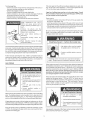
VENT CONNECTIONS TO BLOWER ASSEMBLY
Except where instructed in this manual, the mixing of 2", 3" and 4" vent
pipe is NOTALLOWED.
If2" pipe is to be used, then a 2"to 3" bell reducer
is recommended.
Figure 21 shows the recommended location for the
bell reducer. If the bell reducer is located at the rubber boot on the
Figure 21 shows the optimal placement of the 2" to 3" or 3" to 4" reducer;
however, the vent can be reduced at any point in the vent system as long
as the maximum vent length is not exceeded.
blower assembly, then a short section of 3" vent pipe needs to be
installed in the rubber boot for proper connection of the 2" to 3" bell
reducer. That length can be the minimum length required for the connection.
If4" pipe is to be used, then a 3" to4" bell reducer is recommended.
Figure 21 showsthe recommended location for the bell reducer. Ifthe
bell reducer is located at the rubber boot on the blower assembly, then
a short section of 3" vent pipe needs to be installed in the rubber boot
for proper connection of the 3" to 4" bell reducer. That length can be
the minimum length required for the connection.
The water heaters covered by this manual are supplied with a 2" Schedule
40 PVC 22.5 ° Vent Terminal. If you decide to vent with 3" or 4" pipe, a
Schedule 40 DWV 45° Vent Terminal must be used. For your convenience,
we have included a screen for both 3" and 4" Vent Terminals.
HGURE21.
VENTING
AND INSTALLATION
Plan the layout of the vent system from the vent termination to the water
heater considering all of the 90 ° and 45 ° elbows plus the number of feet
of pipe that would be needed to install the total vent system. The water
heater must be vented to the outdoors as described in these instructions.
DO NOT connect this water heater to an existing vent or chimney. It must
be vented separately from all other appliances. Nonmetallic vent may be
used if it has "Heat Deflection Temperature" (HDT@66 psi) or 455 kPa of
at least 157°F or 69°C. Typical nonmetallic vent materials meeting this
requirement are: PVC (Schedule 40, ASTM D-1785), Coex Cellular Core
(Schedule 40, ASTM F-44! ), CPVC (Schedule 40, ASTM Do2846), ABS
(Schedule 40, ASTM Do2661 ). The fittings, other than the supplied Vent
Termination should be equivalent to the following: PVC (Schedule 40,
DWV, ASTM D-2665), CPVC (Schedule 40, DWV, ASTM F-438), ABS
(Schedule 40 DWV, ASTM Do2661 ).
The vent piping should be connected to the blower with a rubber
adapter and secured with hose clamps. The adapter and clamps are
provided with the heater.
Even though the flue gas temperature leaving the blower is between
140°F (69°C) and 175°F (79°C), some installations will have water
vapor condense in the vent piping. If this occurs, then adequate means
of draining and disposing of the condensate needs to be made by
the installer.
CONDENSATION
• For Schedule 40, 2" CPVC vent pipe: Every 5 feet (1.5 m).
Condensate formation does not occur in all installations of power vented
water heaters, but should be protected against on installations where it
can form in the venting system. Condensation in the venting system of
power vented water heaters is dependent upon installation conditions
including, but not limited to ambient temperature and humidity of installation
location, ambient temperature and humidity of venting space, vent
discharge and slope, and product usage. In certain conditions, installations
in unconditioned space or having long horizontal or vertical vent runs
may accumulate condensate. In these conditions, the vent pipe should
be sloped downward away from the blower assembly 1/4" (6.4 mm) per
five feet (1.5 m) of pipe but not more than 1 1/2" (3.8 cm) in the total vent
length. If the vent piping is vented level or sloped upwards away from
the blower assembly, then adequate means for draining and disposing
of the condensate needs to be made by the installer (if condensate is
detected). If you have condensate, then a 3/8" drain hose can be connected
to the built-in drain port of the rubber boot on the blower assembly. For
your convenience, the rubber boot is supplied with a removable cap on
the built-in drain port. Prior to operating the water heater, make sure the
removable cap is installed on the drain port (ifa drain hose is not needed).
• For Schedule 40, 3" CPVC vent pipe: Every 6 feet (1.8 m).
MAXIMUI_I VENT LENGTHS
• For Schedule 40, 4" CPVC vent pipe: Every 6.5 feet (2.0 m).
40.000 BTU Units:
It is imperative that the first hanger (or support) be located on the horizontal
run immediately adjacent to the first 90-degree elbow from the vertical
rise. Support method used should isolate the vent pipe from the floor
joists or other structural members to prevent the transmission of noise
and vibration.
Do not support, pin, or otherwise secure the venting
system in a way that restricts the normal thermal expansion and
contraction of the chosen venting material.
For 2" Venting, the maximum equivalent
feet of pipe allowed
is 40 feet (12.2 m). This does not include the supplied vent termination
for the water heater. For the 2" venting, one 90 ° elbow is approximately
equal to 5 feet (1.5 m). One 45 ° elbow is approximately equal to 2.5
feet (0.8 m). It is recommended that at least 2 feet (0.6 m) of spacing
be used in between all 45 ° elbows and all 90°elbows.
The cement used should be as recommended
by the vent pipe
manufacturer. See the instructions on pages 20 and 21 for the proper
method of cutting and cementing the PVC pipe and fittings.
The unit may be vented horizontally through a wall or vertically through
the roof. Pipe runs must be adequately supported along both vertical
and horizontal runs as follows:
• For Schedule 40, 2" PVC, ABS, Coex Cellular Core vent pipe: Every
3 feet (0.9 m).
• For Schedule 40, 3" PVC, ABS, Coex Cellular Core vent pipe: Every
3.5 feet (1.1 m).
• For Schedule 40, 4" PVC, ABS, Coex Cellular Core vent pipe: Every
4 feet (1.2 m).
For 3" Venting, the maximum equivalent
feet of pipe allowed
is 120 feet (36.6 m). This does not include the Vent Termination (supplied
locally) for the water heater. For the 3" venting, one 90 ° elbow is
approximately equal to 5 feet (1.5 m). One 45 ° elbow is approximately
equal to 2.5 feet (0.8 m). It is recommended that at least 2 feet (0.6 m)
of spacing be used in between all 45 ° elbows and all 90°elbows.
If the water heater is being installed as a replacement for an existing
power vented heater in pre-existing venting, a thorough inspection of
the existing venting system must be performed prior to any installation
work. Verify that the correct material as detailed above has been
used, and that the minimum or maximum vent lengths and terminal
location as detailed in this manual have been met. Carefully inspect the
entire venting system for any signs of cracks or fractures, particularly
at the joints between elbows and other fittings and the straight runs of
vent pipe. Check the system for signs of sagging or other stresses in
the joints as a result of misalignment of any components in the system.
If any of these conditions
are found, they must be corrected
in
accordance
with the venting instructions
in this manual before
completing the installation and putting the water heater into service.
For 4" Venting, the maximum equivalent
feet of pipe allowed
is 160 feet (48.8 m). This does not include the Vent Termination (supplied
locally) for the water heater. For the 4" venting, one 90 ° elbow is
approximately equal to 8 feet (2.4 m). One 45 ° elbow is approximately
equal to 4 feet (1.2 m). It is recommended that at least 2 feet (0.6 m) of
spacing be used in between all 45 ° elbows and all 90°elbows.
17
VENTING
Breathing
Vent pipes serving power vented appliances are classified by building
codes as "vent connectors".
Required clearances from combustible
materials must be provided in accordance with information in this manual
under FACTS TO CONSIDER ABOUT THE LOCATION and VENT
TERMINAL INSTALLATIONS, and with the National Fuel Gas Code and
local codes.
Hazard
° Catben
Monoxide
Install vent system in accordance
codes.
" Do not operate
damaged.
water
Gas
VENT TERMINAL INSTALLATION
with
After the point of termination has been determined, use the cover
plate as a template to mark the hole for the vent pipe to insert
through the wall. BEWARE OF CONCEALED WIRING AND PIPING
INSIDE OFWALL
heater if hood
- High altitude odhce must be installed for
operation above7,700 feet (2,347 m)
If the Vent Terminal is being installed on the outside of a finished
wall, it may be easier to mark both the inside and outside walk
Align the holes by drilling a hole through the center of the template
from the inside through to the outside. The template can now be
positioned on the outside wall using the drilled hole as a centering
point for the template.
o Do not operate if soot buildup
" Do not obstruct water heater air intake
with insulating jacket.
- Do not place cheraicd vapor emitting
products near water heater
" Gas and carbon monoxide detectors
are available.
A) MASONRY SIDE WALLS
Chisel an opening approximately
marked circle.
,, Never operate the heater unless it _s
vented to the outdoors and has adequate
air supply to avoid risks of improper
operation, fire, explosion, or asphyxiation
o Make sure the flue baffle and flue restrtctor
one half inch larger than the
B) WOODEN SIDE WALLS
Drill a pilot hole approximately
one quarter inch outside of the
marked circle. This pilot hole is used as a starting point for a
saws=all or sabre saw blade. Cut around the marked circle staying
approximately
one quarter inch outside of the line. (This will allow
the vent pipe to easily slide through the opening. The resulting
gap will be covered up by the vent terminal cover plates.) Repeat
this step on inside wall if necessary.
ring are properly aligned and inserted on
top of the flue. This can be checked
through the dilution air inlet of the blower
assemb_j. For _ewing, the Air Intake screen
d the blower assembly will have to be
removed Replace after the check is made
Breathing carbon monoxide can cause brain damage or death
Always read and understand instruction manual
When the vent piping cannot pass through an outside wall at a
height greater than or equal to 12" above the ground (or above
snow accumulation level), then the installation can be modified as
shown below.
The vent system must terminate
so that proper clearances
are
maintained as cited in local codes or the current edition of the National
Fuel Gas Code, ANSi Z223.1/NFPA54,
7.3.4e and 7.8a,b, as follows:
1. The exit terminals of a mechanical vent system shall be not less
than 7 feet (2. ! 3 m) above grade when located adiacent to public
walkways, see Figure 23.
2. A venting system shall terminate at least 3 feet (91 cm) above any
forced air inlet located within 10 feet (3.1 m), see Figure 23.
3. The venting system shall terminate at least 4 feet (1.2 m) below, 4
feet (! .2 m) horizontally from or, 12 in. (30 cm) above any door,
window or gravity air inlet into any building.
12"MIN. ABOVE
GROUNDORSNOW
ACCUMULATIONLEVEL
The manufacturer also recommends that the vent termination should
not be installed closer than 3 feet (91 cm) from an inside corner of an
L shaped structure and not be less than 12 in. (30 cm) above grade.
The vent shall terminate a minimum of 12" (30.5 cm) above expected
snow, all level to prevent blockage of vent termination, see Figure 23.
4. In cold climates, it is recommended that vent termination not be mounted
directly above or within 3 feet (91 cm) horizontally from an oil tank vent or
gas meter to avoid potential freeze-up from condensation, see Figure 23.
Plan the vent system layout so that proper clearances
from plumbing and wiring.
are maintained
FIGURE22.
18
Minimum
3ft. (91 cm}
Minimum 3 ft. (91 era) within a
hMght of 15_. (4.6 m) above
meter/regulator
assam bly
Minim,
12 in= (30 am)
from sides of
permanently
cUosed window
that reay be open
below a window that
may be open
Minimum 12 in. (30 era) above
window or door that may be open
[]
VENT TERMINAL
(_ AIR SUPPLY
INLET
1. Permitted only if veranda, porch, deck or balcony
[] AREA
WHERE
TERMINAL
from side of window
that may be open
suppUy inUatintobuilding
or combustion air iMet
to another appUianee
IS NOT PERMITTED
is fully opened on a minimum of two sides beneath the floor
2. A vent shall not terminate above a sidawaUk or paved driveway that is located between two single family dwelUings and sePces bMh dwelhgs,
FIGURE 23.
This unit can vent through 2", 3" or 4" nonmetallic
VERTICAL VENT TERMINATION RESTRICTIONS
pipe and fittings.
The vent pipe installation can be started from either the blower discharge
or the termination wall. Keep in mind the total vent system (pipe and
elbows) when installing
the vent system,
see VENTING
AND
INSTALLATION AND MAXIMUM VENT LENGTHS, page 17.
1. Minimum of twelve !2" (30.5 cm) above the roof or twelve 12"
(30.5 cm) above the anticipated snow level Provide proper support
for all pipe protruding
through
the roof.
'VENT
TERMINAL
MORTAR
WALL
OR
SILICONE
CAULK
PLATE
{OPTIONAL}
/
/
PVC VENT
TERMINAL
WITH
MESH PROTECTUVE
SCREEN
INSI[:)E
FROM
WATER
HEATER
PVC
COUPLING
FIGURE24.
The vent terminal should be kept as dose as possible to the outside
wall, but you need to allow at least 1.5" (3.8 cm) of pipe past the wall,
for the wall flange and vent terminal to mount on the pipe.
Before the vent terminal is installed, caulk (not supplied) around the pipe
on the exterior wall and install the optional wal! flange. The flange can be
held to the outside wall by placing some of the caulking on the back of the
flange. The wall flange is supplied for decorative purposes only and is
not a requirement for the vent termination (if not needed by the installer).
VERTICAL VENT THROUGH ROOF
This unit is approved for venting through the roof with the type vent
terminal that is included with the unit. A proper flashing or "BOOT"
should be used to seal the pipe where it exits the roof.
The total vent system should not exceed that which is specified,
VENTINGAND INSTALLATION, page 17.
*ALL PUPE PROTRUDRNG
SHOULD
BE PROPERLY
THROUGH
THE
SUPPORTED.
ROOF
RGURE 25.
see
2. 4' (! .2 m) from or 1' (0.3 m) above any gable, dormer, or other roof
structure with access to interior of building (i.e.=vent, window etc.).
All of the pipe should be secured as per the instructions in the instructions
in the VENTING AND INSTALLATION, page 17.
3. 3' (0.9 m) above any forced air inlet located within 10' (3.0 m).
19
VENT PIPE PREPARATION
formamide (DMF) may be included to act as a retarding agent to extend
curing time. Select the proper cement; Schedule 40 cement should be
used for Schedule 40 pipe. Never use all-purpose cements, commercial
glues and adhesives orABS cement to join PVC or CPVC pipe and fittings.
1. INITIAL PREPARATION
A.
Make sure the solvent cement you are planning to use is
designed for the specific application you are attempting.
B.
Knowthe physical and chemical characteristics and limitations
of the PVC and CPVC piping materials that you are about to use.
C.
Know the reputation of your manufacturer
D.
Know your own qualifications
or those of your contractor.
The solvent welding technique of joining PVC and CPVC pipe
is a specialized skill just as any other pipe fitting technique.
E
Closely supervise the installation
job before start-up.
Fire Hazard
P_imereand earr_nts are extremelyflammable, and
must not be stored or used near heat or open flame.
and their products.
, Also, use only in a well ventilated area.
APPUCATORS
and inspect the finished
R
Contact the manufacturer, supplier, or competent consulting
agency if you have any questions about the application or
installation of PVC and CPVC pipe.
G
Take the time and effort to do a professional job. Shortcuts
will only cause you problems and delays in start-up. By far,
the majority of failures in PVC and CPVC systems are the
result of shortcuts and/or improper ioining techniques.
Select a suitable pure bristle type paint brush. Use a proper width
brush or roller to apply the primer and cement (see chart below).
Speedy application
of cement is important due to its fast drying
characteristics.
IMPORTANT NOTE: A dauber type applicator should
only be used on pipe sizes 2" and below. For larger diameter pipe, a
brush or roller must be used.
RECOMMENDED BRUSH* SIZE FOR PRIMER
AND CEMENT APPUCATIONS
Nominam Pipe
2. SELECTmON OF MATERIALS
Size Brush
(_PS)
Cutting Device - Saw or Pipe Cutter
Deburring
Width
(INS.)
2
1o1!2
3
1o1!2 o2o1!2
Tool, Knife, File, or Beveling Machine (2" and above)
*USE ONLY NATURAL BRmSTLE
Brush - Pure Bristle
Rag - Cotton (Not Synthetic)
3. MAKING THE JOINT
Primer and Cleaner
A, Cutting
Pipe must be squarely cut to allow for the proper interfacing of the
pipe end and the fitting socket bottom. This can be accomplished
with a miter box saw or wheel type cutter. Wheel type cutters are
not generally recommended for larger diameters since they tend to
flare the corner of the pipe end. If this type of cutter is used, the
flare on the end must be completely removed.
SoNent Cement - PVC for PVC Components
Components
Containers
and CPVC for
- Metal or Glass to hold Primer and Cement.
CPVC
Select the
type of PVC or CPVC materials to be used on the basis of their
application with respect to chemical resistance, pressure rating,
temperature characteristics, etc.
NOTE: Power saws should be specifically
Insertion Tool - Helpful for larger diameter pipe and fittings 6 inches
(15.2 cm) and above.
PRIMER
It is recommended that Tetrahydrofuran
(THF) be used to prepare the
surfaces of pipe and fittings for solvent welding. Do not use water,
rags, gasoline or any other substitutes for cleaning PVC or CPVC
surfaces. Achemical cleaner such as MEK may be used.
CEMENT
The cement should be a bodied cement of approximately 500 to 1600
centipoise viscosity containing 10-20% (by weight) virgin PVC material
solvated with tetrahydrofuran
(THF). Small quantities of dimethyl
STEPA
2O
designed to cut plastic pipe.
B.Deburring
Use
aknife,
plastic
pipe
deburnng
tool,
orfiletoremove
burrs
from
theend
ofsmall
diameter
pipe.
Besure
toremove
allburrs
from
around
theinside
aswellastheoutside
ofthepipe.
Aslight
chamfer
(bevel)
ofabout
IO°15°should
beadded
totheend
topermit
easier
insertion
ofthepipe
into
theend
ofthe
fitting.
Failure
tochamfer
theedge
ofthepipe
may
remove
cement
from
thefitting
socket,
causing
thejoint
toleak.
STEPE
1(
R Joint assembmy
Working quickly, insert the pipe into the fitting socket bottom and
give the pipe or fitting a 1/4 turn to evenly distribute the cement. Do
STEP B
not continue to rotate the pipe after it has hit the bottom of the fitting
socket. A good joint will have sufficient cement to make a bead all
the way around the outside of the fitting hub. The fitting will have a
tendency to slide back while the cement is still wet so hold the ioint
C. Test dry fit of the joint
Tapered fitting sockets are designed so that an interfaced fit should
occur when the pipe is inserted about 1/3 to 2/3 of the way into the
socket. Occasionally,
when pipe fitting dimensions
are at the
tolerance extremes, it will be poseible to fully insert dry pipe to the
bottom of the fitting socket. When this happens, a sufficient quantity
of cement must be applied to the joint to fill the gap between the pipe
and fitting. The gap must be filled to obtain a strong, leakofreeioint.
D. Inspection,
cleaning,
priming
Visually inspect the inside of the pipe and
all dirt, grease or moisture with a clean
clean the surfaces, a chemical cleaner
possible damage such as splits or cracks
together
fitting sockets and remove
dry rag. If wiping fails to
must be used. Check for
and replace if necessary.
f,
Depthoofoentry
Marking the depth of entry is a way to check if the pipehas reached
the bottom of the fitting socket in Step R Measure the fitting depth
and mark this distance on the pipe O.D. You may want to add
several inches to the distance and make a second mark as the
primer and cement will most likely destroy
for about 15 seconds.
STEPF
G,
Cleanup
and joint movement
Remove all excess cement from around the pipe and fitting with a
dry cotton rag. This must be done while the cement
your first one.
is still soft.
The ioint should not be disturbed immediately after the cementing
procedure, and sufficient time should be allowed for proper curing
of the joint. Exact drying time is difficult to predict because itdepends
on variables such as temperature, humidity and cement integrity.
Apply primer to the surface of the pipe and fitting socket with a natural
bristle brush. This process softens and prepares the PVC or CPMC for
the solvent cementing step. Move quickly and without hesitation to the
cementing procedure while the surfaces are still wet with primer.
For more specific information,
cement manufacturer.
E, Application
of solvent
cement
. Apply the selvent cement evenly and quickly around the outside of the
pipe at a width a little greater than the depth of the fitting socket.
. Apply a light coat of cement evenly around the inside of the
fitting socket. Avoid puddling.
• Apply a second coat of cement to the pipe end.
you should
Cons of cement and primer should be closed at all
times when not in use to prevent evaporation of
chemicals and hardening of cement.
They are also very flammable and should be kept
away from heat or flame.
STEPG
21
contact
your solvent
FOR YOUR
SAFETY
WARNING:
explosion
life.
mfyou
may result
READ
BEFORE
do not follow
causing
property
these
OPERATING
instructions
damage,
exactly,
personal
a fire
or
injury or ross of
BEFORE OPERATING: ENTIRE SYSTEM MUST BE FILLED WiTH WATER AND AiR PURGED FROM ALL LINES.
A. This appliance
does not have a pilot. It is equipped
an ignition device which automatically
Do NOT try to light the burner
with
•
lights the burner.
by hand,
B. BEFORE OPERATmNG smell all around the appliance area
for gas. Be sure to smell next to the floor because
Do not try to light any appliance.
•
Do not touch any electric switch;
gas supplier,
call the fire
will not push in,
don't try to repair them, call a qualified service technician.
Force or attempted repair may result in a fire or explosion.
D. Do not use this appliance
Immediately cell your gas supplierfrom
Follow the gas supplier's
your
Never use tools. If the control buttons
some
water, immediately
Do not use any phone in your building.
•
reach
C. Use only your hand to push in the gas control buttons.
gas is heavier than air and will settle on the floor.
WHAT TO DO iF YOU SMELL GAS:
•
If you cannot
department.
if any part has been under
contact a qualified installer or service
agency to replace a flooded water heater. Do not attempt
a neighbor's phone.
to repair the unit! It must be replaced!
instructions.
OPERATING iNSTRUCTiONS
4. This appliance
is equipped
with
a device
which
automatically lights the burner.
DO NOT TRY TO UGHT THE BURNER BY HAND.
5. Wait five (5) minutes
If you then smell _
safety
to clear out any gas.
STOP! Follow "B" in the
his label. If you don't smell
gas, go to the next step.
6. Turn on all electrical power to the appliance.
7.
8.
1. f_
STOP!
Read the safety information
above,
the COOLER
_
setting by first pressing
the
COOLER {-\-}')and HOTTER j_}-_ buttons together
and
holding
button.
([:3
for 1 second.
and HOTTER,{__
Then
press the HOTTER
If the appliance will not operate, follow the instructions
"TO TURN OFF GAS TO APPLIANCE"
and call your
technician or gas supplier.
V is approximately
to the lowest setting by first pressing
CAUTION:
buttons together and
of
holding for ! second. Then press the COOLER {_::)button
scald
manual
until the WARM indicator light appears.
3. Set the "ON/OFF"
to desired
9. WATERTEMPERATUREADJUSTMENT
on this label.
2. Set the thermostat
Set thermostat
switch on the blower control box to the
120°F.
Hotter
injury.
before
water
Consult
changing
increases
the
the
risk
instruction
temperature.
WARNmNG:TURN OFF ALL ELECTRIC
POWERBEFORESERVICING
"OFF" position.
TO TURN OFF GAS TO APPLIANCE
1. Set the thermostat to the lowest setting by first pressing the COOLER _:_!,and HOTTER _
for 1 second. Then press the COOLER
{_
button until the WARM indicator light appears.
2. Set the ON/OFF switch on the blower control box to the "OFF" position.
3. Turn off all electric power to the appliance
if service is to be performed.
22
buttons together and holding
TEMPERATURE REGULATION
The water heater
should
be located
in an area where
the general
public does not have access.
Due to the nature of the typical gas water heater, the water temperature
in certain situations may vary up to 30°F (16.7°C) higher or lower at the
The water
temperature
point of use such as, bathtubs,
temperature;
Press ng the "COOLER":-_... button decreases temperature
showers,
sink, etc.
setting
was
factory
and pressing the "HOTTER",:_::_} button increases
Any water heater's
intended
purpose
hot water can present a scald hazard. Depending
and the people involved (adults, children, elderly, infirm,
etc.) scalding
may occur at different temperatures.
Some states require settings at specific lower temperatures.
To avoid any unintentional
risk of scalding.
temperature
that lower water temperatures
It is further recommended,
be set for the lowest
hot water needs.
operation
control has a tamper
be used to avoid the
temperature
which
satisfies
the most energy
your
1. "Wake
efficient
the approximate
water temperatures
settings. Short repeated
at
indicators
temperature
by holding
adjustment
down
both
buttons at the
the control will go back to "Sleep" mode.
at the point of use to
using lower temperature
setting follow these instructions:
on for 30 seconds if no further buttons are pressed. After 30 seconds
setting by up to 30°F (17°C). If you experience
this type of use you should consider
to reduce scald hazards.
settings, the
the temperature
same time for one second, see Figure 26. One or two of the
temperature indicators will light up. These indicators will only remain
heating cycles caused by
small hot water uses can cause temperatures
exceed the thermostat
produced
and "HOTTER"
in water temperature
feature for changing
Up" the temperature
"COOLER"
of the water heater.
various thermostat
changes
resistant
setting. To change the temperature
in all cases, that the water
This will also provide
Figure 26 shows
the temperature.
Setting the water heater temperature at 120°F (4g°c) (Approx. "V"
mark on temperature setting of gas valve) will reduce the risk of scalds.
on the
time element,
It is recommended
at the lowest
is to heat water. Hot water is
needed for cleansing, cleaning, and sanitizing (bodies, dishes, clothing).
Untempered
set
2. Release both of the temperature
adjustment
buttons.
settings
a. To decrease
the temperature
press and release
the "COOLER"
button until the desired setting is reached.
Valves for reducing
the point-of-use
hot water are available,
temperature
by mixing cold and
see Figure 15. Also available are inexpensive
devices that attach to faucets to limit hot water temperatures.
b. To increase the temperature press and release
button until the desired setting is reached.
Contact
the "HOTTER"
a licensed plumber or the local plumbing authority.
NOTE: Holding down the button will not continue to lower or raise the
Water
temperature
over
temperature
125°F
(52°0)
can cause severe
burns
instantly resulting in severe iniury or
death.
Children,
the
elderly,
and
setting.
each temperature
Should overheating
water
the
before
bathing
or
limiting
valves
are
and released
for
occur or the gas supply fail to shut off, turn off the
manual gas control valve to the appliance.
physically or mentally disabled are at
highest risk for scald injury_
Feel
The button must be pressed
change desired.
TE M PE RATU RE IN DICATORS
showering.
Temperature
available.
Read
instruction
temperature
manual
for safe
setting.
HOT WATER CAN SCALD: Water heaters are intended to produce hot
water. Water heated to a temperature
which will satisfy space heating,
clothes washing,
dish washing,
and permanently
injure you upon contact. Some people are more likely
to be permanently
and other sanitizing needs can scald
injured by hot water than others. These include the
elderly, children, the infirm, or physically/mentally
handicapped. If anyone
using hot water in your home fits into one of these groups or if there is
a local code or state law requiring
a certain temperature
hot water tap, then you must take special precautions.
using the lowest possible
temperature
water at the
In addition
setting that satisfies
to
TEMPERATURE
ADJUSTMENT
BUTTONS
your hot
water needs, a means such as a mixing valve, shall be used at the hot
Display
water taps used by these people or at the water heater. Mixing valves
VABC
are available at plumbing supply or hardware stores, see Figure !5.
Follow manufacturer's instructions for installation of the valves. Before
changing the factory setting on the thermostat,
Regulation"
I C-Flashing
read the "Temperature
section in this manual, see Figure 26.
= approx
160°F (71°C)
ooo00o
B = approx. 140F
0000@0
000@00
(60C)
A = approx. 130°F (54°C)
V = approx. 120°F (49°C)
Never allow small children to use a hot water tap, or to draw their own
bath water. Never leave a child or handicapped
a bathtub or shower.
person unattended
WARM = approx
in
About 1/2 seconds
C = approx. 150°F (66°C)
80°F
27°C
00@000
@00000
FIGURE 26,
23
!
About 1-1/2 seconds !
Less than 5 seconds 1
About 30 seconds
More hart 5 m nutes
START U P CONDmONS
Thermal Expansion
Tank Specifications
Tank
CONDENSATE
Whenever the water heater is filled with cold water, some condensate
will form while the burner is on. Awater heater may appear to be leaking
when in fact the water is condensate. This usually happens when:
Mode_
Number
a. A new water heater is filled with cold water for the first time.
b. Burning gas produces water vapor in water heaters, particularly
high efficiency models where flue temperatures
are lower.
c. Large amounts of hot water are used in a short time and the refill
water in the tank is very cold.
Dimensions
in inches
Capacity
In Gallons
Diameter
Pipe
Fitting
Length
On Tank
153.331020
2
8 (203 ram)
153.331050
5
11 (279 ram) 14=3/4 (375 mm)
Expansion
12=3/4 (323 ram) 3/4" Male
3/4" Male
Tank Sizing Chart
Inmet*
Water
Heater Capacity
(Gallons)
Water
Moisture from the products of combustion condense on the cooler tank
surfaces and form drops of water which may fall onto the burner or
other hot surfaces to produce a "sizzling" or "frying" noise.
30
40
80
66
80
Expansion
Tank
40psi
2
2
2
5
5
50psi
2
2
2
5
5
Capacity
Needed
60psi
2
2
5
5
5
70psi
2
2
5
5
5
80psi
2
5
5
5
5
Preseure
Because of the suddenness and amount of water, condensate water
may be diagnosed as a "tank leak". After the water in the tank warms
up (about 1=2 hours), the condition should disappear.
Do not assume the water heater is leaking until there has been enough
time for the water in the tank to warm up.
An undersized water heater will cause more condensation. The water
heater must be sized properly to meet the family's demands for hot
water including dishwashers, washing machines and shower heads.
*Highest
recorded
regulated
water
NOTE:
charge,
Excessive condensate
may be noticed during the winter and eady
spring months when incoming water temperatures are at their lowest.
inlet water
pressure
in a 24 hour
period
or
a 40 psi
air
pressure.
Expansion
If the inlet
tanks
are
water
pressure
pre=charged
with
is higher
expansion
tank's
air pressure
must
that pressure,
but must not be higher
than
40 psi, the
be adjusted
than 80 psi.
to match
Good venting is essential for a gas fired water heater to operate properly
as well as to carry away products of combustion and water vapor.
WATER HEATER
COLD WATER
INLET FITTING
SMOKE/ODOR
It is not uncommon to experience a small amount of smoke and odor
during the initial start-up. This is due to burning off of oil from metal
parts, and will disappear in a short while.
(3)
PRESSURE
REDUCING
VALVE WITH
BY-PASS
THERMAL EXPANSmON
improper
(2)
PRESSUREGAUGE
installation
and use may resamt
in property damage,
Avoid water heater damage.
. Install thermal expansion tank or device if necessary.
. Contact qualified installer or Sears Service Center,
RECOMMENDED
mNSTALLATION
(VERTICAL MOUNTING}
WATER HEATER
COLD WATER
INLET FITTING
Water supply systems may, because of such events as high line
pressure, frequent cut-offs, the effects of water hammer among
others, have installed devices such as pressure reducing valves, check
valves, back flow preventers, etc. to control these types of problems.
When these devices are not equipped with an internal by-pass, and no
other measures are taken, the devices cause the water system to be
closed. As water is heated, it expands (thermal expansion) and closed
systems do not allow for the expansion of heated water.
in controlling
these situations,
FLOOR, CEILING JOIST, ETC,
_
EXPANSION
TANK
(21
PRESSURE
(3)
REDUCING
STRAPPING
(1)
The water within the water tank expands as it is heated and increases
the pressure of the water system. If the relieving point of the water
heater's temperature=pressure
relief valve is reached, the valve will
release the excess pressure. The temperature-pressure
relief
valve
is not intended
for the constant
relief
of thermal
expansion.
This is an unacceptable condition and must be corrected.
It is recommended
that any devices installed which could create a
closed system have a by-pass and/or the system have an expansion
tank or device to relieve the pressure built by thermal expansion in the
water system. Expansion tanks are available through Sears stores
and Sears Service Centers.
Contact Sears Service Center for
assistance
INLET COLD
WATER SHUT=OFF
PRESSUREGAUGE
/
VALVE
WITH
BY=PASS
J
f
INLET COLD
WATER SHUT*OFF
ALTERNATE RECOMMENDED INSTALLATION
(HORIZONTAL MOUNTING)
FIGURE27.
see Figure 27.
24
STRANGE
SOUNDS
Possible
noises
duetoexpansion
Do not remove the anode leaving
the tank unprotected,
doing so, aH warranty
on the water heater tank is voided.
and contraction of some metal parts
during periods of heat-up and cool-down do not necessarily represent
harmful or dangerous
By
"AmR"mNNOT WATER FAUCETS
conditions.
Condensation causes sizzling and popping within the burner area during
heating and cooling periods and should be considered normal. See
"Condensate" in this section.
E×plosion
Hazard
OPERATIONAL CONDITIONS
" Flammable hydrogen gases may be present
SMELLYWATER
• Keep all ignition sources away from faucet
when turning on hot water,
In each water heater there is installed at least one anode rod (see
parts section) for corrosion protection of the tank. Certain water
conditions will cause a reaction between this rod and the water. The
most common complaint associated with the anode rod is one of a
"rotten egg smell" in the hot water. The smell is a result of four factors
which must all be present for the odor to develop:
HYDROGEN
GAS: Hydrogen gas can be produced in a hot water
system that has not been used for a long period of time (generally two
weeks or more). Hydrogen gas is extremely flammable and explosive.
To prevent the possibility
of injury under these conditions,
we
a. A concentration
of sulfate in the supply water.
b. Little or no dissolved oxygen in the water.
c. A sulfate reducing bacteria which has accumulated within the water
heater (this harmless bacteria is nontoxic to humans).
d. An excess of active hydrogen in the tank. This is caused by the
corrosion protective action of the anode.
recommend the hot water faucet, located farthest away, be opened
for several minutes before any electrical
appliances
which are
connected to the hot water system are used (such as a dishwasher or
washing machine). If hydrogen gas is present, there will probably be
an unusual sound similar to air escaping through the pipe as the hot
water faucet is opened. There must be no smoking or open flame near
the faucet at the time it is open.
Smelly water may be eliminated or reduced in some water heater
models by replacing the anode(s) with one of less active material, and
then chlorinating the water heater tank and all water lines. Contact
Sears Service Center for further information
concerning
Anode
Replacement
Kit #9001453 and this chlorination treatment. Anode
replacement and chlorination of the tank are not covered by the water
heater's limited warranty.
HIGH WATER TEMPERATURE
SHUT OFF SYSTEM
This water heater is equipped
with an automatic
gas shut-off system.
This system works when high water temperatures
are present. Turn
"OFF" the entire gas supply to the water heater. The high temperature
shut-off is built into the gas control valve. It is non-resettable. If the high
temperature shut-off activates, the gas control valve must be replaced.
If the smelly water persists after the anode replacement and chlorination
treatment, we can only suggest that chlorination or aeration of the
water supply be considered to eliminate the water problem.
Contact your gas supplier or Sears Service Center.
VENTING SYSTEM INSPECTION
2.
Damage or deterioration which could cause improper
leakage of combustion products.
venting or
Be sure the vent piping is properly connected to prevent escape
dangerous flue gasses which could cause deadly asphyxiation.
Breathing
Hazard o Carbon
°_"-*
Monoxide
Obstructions and deteriorated
risk or asphyxiation.
Gas
_, Flue gases may escape if vent pipe is
not connected.
_, Be
alert
for
obstructed,
sooted
system
death.
can cause
pool chemicals, calcium and sodium chloride, waxes, bleach and process
chemicals are typical compounds which are potentially corrosive.
If after inspection of the vent system you found sooting or deterioration,
something is wrong. Call the local gas utility to correct the problem and
and vent
serious
iniury
vent systems may present serious health
Chemical vapor corrosion of the flue and vent system may occur if air for
combustion contains certain chemical vapors. Spray can propellants,
cleaning solvents, refrigerator and air conditioner refrigerants, swimming
or
deteriorated
vent system
to avoid
serious injury or death.
,, Do not store corrosive chemicals in
vicinity of water heater.
Chemical corrosion of flue
of
or
clean or replace the flue and venting before resuming operation
water heater.
of the
Breathing carbon monoxide can cause brain damage or death.
BURNER OPERATIONANDINSPECTION
Always read and understand instruction manual.
At least once a year a visual inspection
system. You should look for:
Flood damage to a water heater may not be readily visible or immediately
should be made of the venting
detectable. However, over a period of time a flooded,water heater w411
create
dangerous conditions which can cause DEATH, SERIOUS BODILY INJURY,
OR PROPERTY DAMAGE. Contact Sears Service Centerto replace a flooded
1. Obstructions which could cause improper venting. The combustion
and ventilation air flow must not be obstructed.
water heater. Do not attempt to repair the unit! It must be replaced!
25
Atleastonce
ayearavisual
inspection
should
bemade
ofthemain
burnerandthehotsurfaceigniterassembly
forproperflame
characteristics
andignition
sequences.
Thiscanbedonebyremoving
theOuter
Doorandviewing
themainburner
operation
through
the
Viewport
ontheInnerDoor,
seeFigure
1.Themainburner
should
provide
complete
combustion
ofgas,ignite
rapidly,
givereasonably
quiet
operation,
andcause
noexcessive
flame
lifting
fromtheburner
ports,
iftheproper
flame
characteristics
arenotevident
(seeFigure
28),make
surethattheflowofcombustion
andventilation
airisnot
blocked
ontheAirIntake
Screen
atthebase
ofthewater
heater
(see
Figure
29),theLintscreen
ontheblower
assembly
(seeFigure
1),and
intheventing
system.
Youshould
alsocheck
forsooting.
Sootisnotnormal
andwillimpair
proper
combustion.
Avisualinspection
ofthemainburner
andHSI
igniterassembly
should
alsobedoneatleastoncea year,see
Figure
28.
Soot
build-up
indicates
aproblem
thatrequires
correction
before
further
use.Turn"OFF"
gastowaterheater
andleaveoffuntilrepairs
are
made,
because
failure
tocorrect
thecause
ofthesooting
canresult
in
afirecausing
death,
serious
injury,
orproperty
damage.
FIGURE29.
A T LEAST ONCE EVERY SIX MONTHS A VISUAL iNSPECTION
SHOULD BE MADE OF THEA/R INTAKE SCREENS ON THE BASE
OF THE WATER HEATERAND
THE BLOWERASSEMBLY.
CLEAN
iF LINTA CCUMULAT/ONS
ARE NOTICED.
INSTALLED
IN SUITABLE
AREA: To insure sufficient
ventilation
and
combustion air supply, proper clearances from the water heater must
be maintained.
See "Facts to ConsiderAbout
the Location" section.
Combustible materials such as clothing, cleaning materials, or flammable
liquids, etc. must not be placed against or adiacent to the water heater
which can cause a fire.
ANODE ROD INSPECTION
Property
FIGURE 28.
Damage
Hazard
Avoid water heater damage.
BURNER CLEANING
Inspection and replacement of anode rod required.
In the event your burner or burner air openings require cleaning, turn
the blower switch to the "OFF" position and allow the burner to cool.
Call Sears Service Center to remove and clean the burner and correct
The anode rod is used to protect the tank from corrosion.
the problem that required the burner to be cleaned.
water tanks are equipped
sacrifices
HOUSEKEEPING
with an anode rod.
itself to protect the tank.
instead
Most hot
The submerged
of corroding
rod
the tank,
water ions attack and eat away the anode rod. This does not affect
the water's taste or color. The rod must be maintained to keep the tank
Vacuumaround baseof waterheaterfordust,dirt,andlinton a regularbasis.
in operating condition.
Anode deterioration
water condition.
conductivity
Fire and Expmosion
Do
not obstruct
Hazard
combustion
on water conductivity,
not necessarily
or pitted anode rod indicates
and should be checked and/or replaced
an anode rod that appears
to be intact.
high water
more often than
Replacement
of a depleted
anode rod can extend the life of your water heater. Inspection
air
be conducted
openings at the bottom of the water
heater
, Do not
depends
A corroded
by a qualified technician,
checked annually after the warranty
use or store flammable
and at a minimum
should
should be
period.
TEMPERATURE-PRESSURE
REUEF VALVE OPERATION
vapor products such as gasoline,
solvents or adhesives in the same
room or area near water heater or
other appliance.
Burn hazard
* Visibly inspect air intake screen at
least once every six months and
clean if accumulated lint.
• Hot water
, Can cause serious injury or death.
Keep
discharge.
clear
discharge
of
relief
valve
outlet.
This water heater unit is supplied with a plasticAir intake Screen that will
filter and prevent lint build°up on the bottom of the flame arrestor of this
heater. To prevent the lint build-up on the arrestor, the lint screen must be
installed on the Base Pan with the "arrows" pointing upwards as shown
in Figure 29. If theAir intake Screen is missing from this heater, please
contact Sears Service Center for a replacement part.
The temperature-pressure
least once a year.
26
relief valve must be manually
operated
at
5. OPEN the water heater drain valve to allow for tank draining.
TEMPERATURE=PRESSURE
NOTE:
mfthe
water
heater
is going
to be shut
down
and
drained
for an extended
period, the drain valve should be
left open with hose connected
amlowing water to terminate
to an adequate
drain.
6.
DISCHARGEPiPE
CLOSE the drain valve.
7. Follow instructions
8.
FIGURE 30.
When checking the temperature=pressure
Follow the lighting instructions on the label or see page 22 under
"Operating instructions" to restart the water heater.
relief valve operation, make
sure that (1) no one is in front of or around the outlet of the temperaturepressure relief valve discharge line, and (2) that the water discharge
will not cause any property damage, as the water may be extremely
hot, see Figure 30.
DRAIN
if after manually operating the valve, it fails to completely reset and
continues to release water, immediately close the cold water inlet to
the water heater, follow the draining instructions,
and replace the
temperature-pressure
relief valve with a new one.
2.
if the temperature=pre_ure relief valve on the appliance weeps or discharges
periodically, this may be due to then_al expansion. You may have a check
valve installed in the water line or a water meter with a check valve. Consult
4.
yourlocalwatersupplierorSearsServiceCenterfor
not plug the temperature=pressure
in the "Filling The Water Heater" section.
furtherinformation.
VALVE
WASHER
REPLACEMENT
(See Figure 31 )
1. Turn "OFF" gas supply to water heater.
Follow"Draining"instructions.
3. Turning counterclockwise
screw handle.
(_
), remove the hex cap below the
Remove the washer and put the new one in place.
5. Screw the handle and cap assembly back into the drain valve and
retighten using a wrench. DQ NOT OVER TIGHTEN.
Do
relief valve.
6.
DRAINING
Follow instructions
in the "Filling The Water Heater" section.
7. Check for leaks.
8.
Follow the lighting instructions in the "Operating
to restart the water heater.
Instructions" section
,, Burn hazard
- Hot water discharge.
• Keep hands clear
valve discharge.
of drain
CAP ASSEMBLY
WASHER
The water heater should be drained if being shut down during freezing
temperatures. Also periodic draining and cleaning of sediment from the
tank may be necessary.
HGURE 31.
1. Set the blower switch to the "OFF" position.
SERVICE
2. CLOSE the cold water inlet valve to the water heater.
3. OPEN a nearbyhotwaterfaucetand
leaveopentoallowfor
If a condition persists or you are uncertain about the operation of the
water heater contact Sears Service Center at 1-800-MY-HOME
R'
draining.
(1=800-46%4663).
4. Connect a hose to the drain valve and terminate to an adequate drain.
27
Usethisguide
tocheck
a"Leaking"
water
heater.
Many
suspected
Read this manual first. Then before checking
"Leakers" are not leaking tanks.
found and corrected.
sure the gas supply has been turned
Often the source of the water can be
"ON" before the tank is completely
If you are not thoroughly familiar with gas codes, your water heater, and
safety practices, contact Sears Service Center to check the 'water heater.
the water heater make
"OFF", and never turn the gas
full of water.
Never use this water heater unless it is completely
filled with water. To
prevent damage to the tank, the tank must be filled with water. Water
must flow from the hot water faucet before
water heater.
A. Water at the blower assembly
out of the combustion
turning "ON" gas to the
is water vapor which has condensed
products.
This is caused by a problem in the
vent. Contact the gas utility.
B. *Condensation
connections
may be seen on pipes in humid weather
or pipe
may be leaking.
C. *The anode rod fitting may be leaking (anode
is located under the
Blower Assembly).
D. Small amounts
of water from temperature-pressure
may be due to thermal
area.
E
expansion
*The temperature-pressure
relief valve
or high water pressure
in your
relief valve may be leaking at the tank
fitting.
R Water from a drain valve may be due to the valve being slightly
opened.
G *The drain valve may be leaking at the tank fitting.
Combustion
products contain water vapor which can condense on
the cooler surfaces
of the tank.
Droplets
burner or run on the floor. This is common
after installation
Water
form and drip onto the
at the time of startoup
and when incoming water is cold.
in the water heater
bottom
or on the floor may be from
condensation, loose connections, orthe relief valve. DO NOT replace
the water heater until a full inspection
is made and necessary
Read and understand
instruction
manual
and safety' messages
before
installing,
operating
or
servicing this water heater,
corrective
Leakage from other appliances, water lines, or ground seepage should
also be checked.
Failure to follow instructions
and
safety messages
could result in
death or serious inju ry_
To check where threaded
Instruction
Manual
with water heater
fitting.
must
of all possible water sources
steps taken.
portion enters tank, insert cotton swab
between jacket opening and fitting. If cotton is wet, follow "Draining"
instructions in the "Periodic Maintenance" section and then remove
remain
Put pipe dope or teflon tape on the threads
and replace.
Then follow"Filling the Water Heater" instructions in the "Installation
Instructions" section.
28
These
guidelines
should
beused
byaqualified
service
agent.
CalJ
Sears
Service
at1-800-4-MY_HOME
<'_
(1-800-469-4663)
forassistance.
Inform
theassociate
thatthisisa"Flammable
Vapor
Ignition
Resistant"
Product.
YA BC
@OO@OO
V
A
B
qj_ OOOl_
T
@ O
C
An open earth ground circuit to the
ignition system.
1. Check that the earth ground connection is
properly connected.
2. Check that the ground conductor on the
water heater is properly connected.
Wiring error or a high resistance
1.
Checkforproperconnectionofline
to
O
earth ground,
2.
neutral that
and the
hot water
wires. heater is securely
Check
connected to earth ground.
A
B
C
Pressure switch remained closed longer
than 5 seconds after the calJ for
heat began.
1.
2.
Pressure switch wiring is incorrect.
Replace pressure switch.
A
B
C
Pressure switch remained open longer
than 5 seconds after the combustion
blower was energized,
1.
2.
3.
Pressure switch wiring is incorrect.
Pressure switch tubing not connected
correctly.
Air intake or exhaust obstructed.
Error in the hot surface ignitor circuit.
1.
2.
Check that all wiring is correct and secure.
Replace hot surface ignitor.
System in lockout.
1.
2.
Gas supply is off or too low to operate.
Hot surface ignitor not positioned
correctly.
Low voltage to the water heater.
Electric polarity to unit is incorrect =test
and correct.
@O
O @
YA
@O@O@@
BC
YA
BC
@00@@0
3.
4.
V
@ O
A
B C
O O
@ @
Y
@ O
A
B
C
Problem in the gas valve driver circuit.
Turn power to the water heater
10 seconds and the back on.
Replace gas control valve.
off for
Turn power to the water heater
10 seconds and then back on.
Replace gas control valve.
off for
off for
2.
Turn power to the water heater
10 seconds and then back on.
Replace gas control valve.
Flame signal sensed out of
propersequence.
1.
Replace gas control valve.
ECO activated.
1.
Replace gas control valve.
1.
Press and release each of the buttons
2.
once.
Replace gas control vaJve.
Water temperature sensor is
either open or short circuited.
1.
2.
Check that all wiring is correct and secure.
Replace gas control valve.
Unitshutsdownandinlockout.
1.
Clean and reinstalJ the air intake screen
2,
Clean and reinstall the lint screen on the
Blower assembly.
2.
Problem with the internal circuit.
1.
@ @ @ O
_' A
B C
2.
Problem with the internal circuit.
1.
@ @ @ @ @ @
@ 0
T
0
A
0
YA
B C
@ 0
B
C
@OO@@@
V
A
B
@ O @ @ O
VA
B
C
One of the temperature
O
buttons stuck closed,
V
A
@@
• " A
B
adjust
C
@O@@O@
@ O
C
@ @
B
C
Unit shuts down.
O O O@ O O
--
@ O
1.
-T A B C
O O O @
Unitshutsdownandinlockout,
29
1.
Check for correct wiring to FV sensor,
2.
3,
Check for open circuits to FV sensor.
Replace FVsensor,
1,
2.
FVsensordetectedpresenceofflammablevapors,
Contact Sears Service Center to determine cause.
These
guidelines
should
beutilized
byaqualified
service
agent.
When
calling
forservice
notify
theservice
agent
thatthisisa"Flammable
Vapor
Ignition
Resistant"
Product.
1.) Blower will not run.
a. "ON/OFF ° control switch turned off.
b.
c.
d.
e.
NOT
ENOUGH
HOT
WATER
Turn switch to the *'ON" position.
Plug blower back into 1 15 VAC outlet.
Repair service to outlet.
Replace thermostat.
Replace control harness
Replace thermostat.
Replace blower assembly.
Blower unplugged.
No power at outlet,
Thermostat defective.
Control harness defective.
f. High 0imitcontrol circuit open.
g. Blower motor defective.
2.) Thermostat problems
a. Thermostat set too 0ow.
b. Thermostat or ECO defective.
Adjust temperature control higher.
Replace thermostat.
3.) Others
a. Heater undersized
b.
c.
d.
e.
Reduce hot water use.
Low gas pressure.
Oncomingwater is usua00¥co0d.
Leaking hot water pipes of fixtures.
Heater not lit or thermostat not on.
Contact gas supplier
ABIow more time for heater to reheat.
Have pBumber check and repair leaks.
Refer to OPERATING INSTRUCTIONS.
Take unit out of service immediately; contact a
Sears Service Center to determine cause.
Defective air flow restrictor.
VENT
PIPE
TOOHOT
(ABOVE
170°0
Not enough dilution airto
mix with flue gases.
Dilution air too hot for mixing with flue gases.
Wrong burner orifice.
Dirt in burner ports.
YELLOW
FLAME
Combustion air path restricted.
Not enough dilution air for proper combustion
on the floor under heater,
Water
CONDENSATION
Water dripping from blower assembly.
WATER
LEAKS
LEAKING
T&P
improperly sealed, hot or coBd supply connections,
relief valve, drain valve, or thermostat threads.
Leakage from other appliances or water lines
Condensation of flue products.
Condensation of flue products.
Thermal expansion in closed water system.
Improperly seated valve.
HOT
WATER
ODORS High sulfate or mineral content in water
(refer
tocathodic Bacteria in water supply
protection)
WATER
TOO
HOT Thermostat set too high.
WATER
HEATER Condensate dripping on burner.
SOUNDS
SIZZLING
- RUMBUNG
Sediment at bottom of heater tank.
SOOTING
BURNER WILL NOT
STAYLIT-GOES
OUT
4-5SECONDS
VENT GAS ODORS
supply.
Proper dilution air must be provided for combustion
and dilution of flue temp. Refer to INSTALLATION section.
Supply air is too hot. Check for heat sources around
andlor blockage of di0ution air intake.
Install correct orifice.
clean burner head.
Check dilution air intake, exhaust venting, and air openings
in bottom base pan for obstructions or blockage.
Check dilution air intake for obstructions or blockage
See CONDENSATION section and Start Up Conditions.
Provide drip "TEE" to catch condensate.
Tighten threaded connections.
Remove cap on Rubber Boot Vent Terminal of Blower
Assembly and install a drain tube to port as per required
codes.
Inspect other app0iances near water heater.
Refer to CONDENSATION
section and Start Up Conditions
Refer to CONDENSATION
section and Start Up Conditions.
Install thermal expansion tank (Do not plug T & P valve).
Check relief valve for proper operation (Do not plug T & P
valve).
Drain and flush heater thoroughly then refill.
Chlorinate
water supply.
Refer to TEMPERATURE
Refer to CONDENSATION
REGULATION
section.
above,
Clean sediment from tank. Refer to DRAINING.
Improper combustiom
Outlet polarity is reversed.
High ambient room temperature.
Dirty or c0ogged air intake screen (at base of
heater).
Dirty or c0ogged lint screen (on blower assembly).
F0ame arrestor opening Mocked.
Refer to Air Requirements on Pages 10 and 11.
Test polarity and correct.
Contact a Sears Service Center to determine cause
Defective gas valve
Lack of air supply_
!m_roper!] !nsta!!ed vent p!p!ng_
Downdraft
Poor combustion
Replace gas vaJve.
Clean and reinsta01 air intake screen.
Clean and reinstall lint screen.
Contact a Sears Service Center to determine cause.
Contact a Sears Service Center to determine cause
3O
THE ECONOMIZER
6 GAS WATER HEATER
TM
153.332040
40 Gallon Naturam Gas
153.332050
50 Gallon Natutat Gas
153.332060
153.332070
40 Gallon Propane (L.P.)
50 Gallon Propane (L.P.)
OUTER
DOOR
(ALTERNATE)
I£to_e|
KeyNo.
1
2
153,33=2040
4
Part Description
Burner Assembly
Burner Head
ice
Burner Tube
6
7
8
9
, Ignition ssem
Inner Door
Inner Door Gasket
uF_'_Baffle
F'[u-&q%strictor
10
11
12
13
14
BlowerAssembly
Air Intake Screen =Base Pan
Inlet Tube
Gas Control Valve
Drain 'dalve
16
17
Outer Door
Anode Rod
9005951
9005958
9003400
9003401
9005959
9003445
9004316
9003406
9003447
9005§62
9002402
9001584
90G5966
§003972
9000071
9003414
9002846
9002847
9002848
9002850
18524%000
9005967
_0-d5968
9005952
9005958
9003400
9003401
9005_9
9003445
9004316
9003406
9002547
9005962
9002402
9001584
9005966
9003891
9000071
9003414
9002846
9002847
9002848
9002850
165249=000
900596"7
90059_8
900397"/
9005969
9003977
905_938
y
2
24" _D_[a_.
Drain Pan w/Side Drain (optional)
28" _D"_m.
Drain Pan w/Side Drain (optional!
Instruction Manual
Air Intake Screen = BlowerAssembly
FV Sensor
FV Sensor Bracket
"21
22
23
24
900_385
153.332050
9005939
9003S_5
25
Nipple (cold inlet or hot outlet)
Not shown
Now
that
a need
any
you have
ever
Sears
exist
Service
purchased
for repair
your
parts
Center
gas water
or service,
or call
heater,
should
simply
contact
Numbers
9005943
9005948
9005954
9005956
9003396
9003401
9005959
9003445
9004316
9003406
9003447
9005963
9002402
9001584
9005966
9003972
9000071
9003414
9002846
9002847
9002848
9002850
9005967
9005968
9005_69
9003977
WHEN
ORDERING
REPAIR
FOLLOWING
INFORMATION:
l o800o4oMYoHOME®
•
MODEL
•
TYPE
•
SERIAL
•
PART DESCRIPTION
PARTS,
ALWAYS
GIVE
NUMBER
(1o800o469o4663).
Be sure
The
to provide
model
on the
rating
number
place
all pertinent
facts
of your
Gas
located
above
Water
when
you call
Heater
the gas
will
control
or visit.
be found
valve.
GAS (NATURAL
(UP.)
NUMBER
THIS IS A REPAIR
31
OR PROPANE
PARTS
UST, NOT A PACKING
UST.
THE
6 YEAR
LIMITED
WARRANTY
ON WATER
HEATER
For six years from date of purchase, if this water heater is installed and operated in a singleofamily home in accordance with the
owner's manual instructions and all local applicable plumbing codes, Sears will supply a free water heater for one that develops
a leak.
For the second through sixth year from purchase date, you must pay the labor cost for installation of water heater.
For commercial, institutional, industrial, or residential use by two or more families, the above limited warranty is only for two years.
During the second year you must pay the labor cost for water heater installation.
1 YEAR EXCLUSIVE
KENMORE
LABOR
WARRANTY
For the first year from the date of purchase, Sears will, free of charge, supply and install new water heater parts for defective
ones or a new water heater for one that develops a leak.
WARRANTY SERWCE
To obtain warranty service, call I=800o4-MyoHOME
United States.
This warranty
"_(1=800-469-4663).
This warranty
applies only while this product is in use in the
gives you specific legal rights and you may also have other rights which vary from state to state.
SEARS, ROEBUCK AND CO., Dept. 817 WA, HOFFMAN ESTATES,BL60179
The price of your water
warrants the installation.
heater
does
not include
a free checkup
service
call. On water heater
installations
arranged
by Sears,
Sears
A charge will be made on service calls due to poor or incomplete installation. These include:
a. Adjusting thermostat
b. Leaks in pipes or fittings
c. Condensation
MASTERPROTECTIONAGREEMENTS
Fast he_p by phone ° phone support from a Sears technician
on
products requiring in=home repair, plus convenient repair scheduling.
Congratulations
on making
a smart purchase.
"four new Kenmord "_
product is designed and manufactured
for years of dependable
operation. But like all products, it may require preventive maintenance
or repair from time to time. That's when having a Master Protection
Agreement can save you money and aggravation.
Purchase a Master Protection Agreement
from unexpected hassle and expense.
now and protect yourself
Power surge
fluctuations.
o
protection
Renta_ reimbursement
longer than promised.
against electrical
if repair of your covered
•
Expert
o
Unlimited
covered
Service
by our 12,000 professional
service
and
no charge
repair specialists.
for parts
and labor
on all
product takes
Once you purchase the Agreement,
a simple phone call is all that it
takes for you to schedule service. You can call anytime day or night, or
schedule a service appointment
The Master Protection Agreement also helps extend the life of your
new product. Here's what's included in the Agreement:
damage due to power
onoline.
Sears has over 12,000 professional repair specialist, who have access
to over 4.5 million quality parts and accessories.
That's the kind of
professionalism
you can count on to help prolong the life of your new
purchase for years to come. Purchase your Master Protection
Agreement today!
repairs.
•
"No4emon"
guarantee = replacement of your covered product if
four or more product failures occur within twelve months.
•
Product
•
Annual
Preventive
extra charge.
replacement
if your covered
Maintenance
Some
[imitations
and exclusions
apply.
additional
information
call 1 °800°827°6655.
SEARS INSTALLATION
SERVICE
For Sears professional
installation
For
and
product can't be fixed.
Check
at your request
= no
of home appliances,
1-800-4-MY-HOME
®
(1=800=469=4863)
www.se3rs.com
The model number of your water heater is found on the model rating plate on the front of the water heater
Roebuck
garage door
openers, water heaters and other major home items, in the U.S.A., call
lo8004oM%HOME'L
For in-home major brand repair service
Call 24 hours a day, 7 days a week (U.S.A. and Canada)
Sears,
prices
and Co., Hoffman
Estates,
IL 60t79
U.S.A.