1
SEARS
OWNERS
MANUAL
MODEL NO.
919.175261
ONE STAGE
AiR COIVIPRE= OR
Record in the spaces provided.
(1) The model number which can be found
on the label on the front of the air tank
saddle.
(2) The code number which can be found
on the foil label on the side of the air
tank.
(3) The Manufacturer's
Number (ASME
Code Compressors only} is located on
the metal data plate which is welded
onto the side of the air tank. (This data
plate is painted the same color as the
tank.)
(4} The Motor Manufacturer's name which
is located on the motor label.
(5) The Motor Mfg. number - also located
on the motor _abel.
Usted
721Y
Air
Compressor
Retain these
numbers
for future
refer-
60684
U.S.A,
once,
iMPORTANT:
Read the Safety Guidelines
and Al! instructions
Carefully
Before Operating
Model No.
ASSEMBLY
0PERATION
MAINTENANCE
REPAIR PARTS
Code No.
Mfg. No.
Motor Mfg. Name
Motor Mfg. No.
Sears,
[
8t9
Roebuck
and
Coo, Chicago,
IL
WARRANTY
...........................................................................
Page
2
SAFETY GUIDELINES ...............................................................
3
WARNING
3
CHART ...................................................................
SPECZFICATION CHART ...........................................................
5
GLOSSARY
5
............................................................................
ACCESSORIES FOR USE WITH
SEARS AIR COMPRESSORS ................................................
5
GENERAL INFORMATION
6
DESCRiPTiON
.........................................................
OF OPERATION ..................................................
6
iNSTALLATION AND 8REAKqN PROCEDURES ............................
Location of Air Compressor .................................................
Piping ..............................................................................
Lubrication and Oil .............................................................
Wiring _nstructions .............................................................
Wiring Diagram ..................................................................
8reakqn Procedures ...........................................................
6
6
7
7
7
7
8
OPERATING PROCEDURES .......................................................
8
MAINTENANCE ......................................................................
Air Compressor .................................................................
Air Filter - inspection and Replacement .................................
Oil - Checking and Changing ...............................................
Air Tank - Draining Water ...................................................
Check Vatve- Inspection and RepJacement ............................
Safety Valve inspection ......................................................
Motor ..............................................................................
Belt - Replacement .............................................................
PuJte¥ and Ftywheel - Alignment ..........................................
8
8
8
9
g
9
£
9
9
I0
TROUBLESHOOTING
10
GUIDE .....................................................
AIR COMPRESSOR DIAGRAM ..................................................
Parts List ..........................................................................
12
13
COMPRESSOR PUMP D_AGRAM ...............................................
Parts List ..........................................................................
14
15
HOW TO ORDER REPAIR PARTS ...............................................
16
FULL ONE YEAR WARRANTY
ON AiR
COMPRESSORS
8fthis air compressor fai_s due to a defect in materia_ or workmanship whhin one year from the date of purchase, return
it to the nearest Sears Service Center/Department throughout the United States and Sears will repair it, free of charge.
This warrant,/gives you specific legal rights and you may have other rights that vary from state to state.
Sears,
Roebuck
and Co., Sears Tower,
Dept.
698!731CR-2_
Chicago,
_L 60684
This manualcontainsinformation
that is important for you to kno_v and understand. This
information relates to protecting your safety and preventing equipmenlt problems. To help you
recognize this information, we use the following symbols. Please read the manuat end pay special
attention to sections headed by these symbo!so
iMPORTANT SAFETY iNFORMATiON o A
HAZARD THAT MIGHT CAUSE SERIOUS
iNJURY OR LOSS OF LIFE.
Information
ment.
for preventing
damage
to equip-
Information
tention to.
that you should pay special at-
NOTE
HAZARDS
WHAT TO
LOOK FOR
CAN OCCUR iF EQUIPMENT
1S NOT USED PROPERLY.
PLEASE READ THE FOLLOWING
CHART.
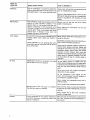
WHAT COULD HAPPEN
HOW TO PREVENT IT
Hot Parts
The compressor head and tubes get hot when
the air compressor is running, if you touch them,
you can be seriously burned.
Never touch the air compressor head or tubes
during or immediately after operation.
Flammable
Vapors
It is normal for the motor's electrical contacts
and pressure switch contacts to spark when the
compressor starts or stops. A spark can ignite
flammable vapors from gasoline, flammable paints
or solvents, causing an explosion or fire.
Operate the compressor in well ventilated
areas that are free of gasoline, flammable paint
or solvent vapors.
if spraying a flammable
material - provide
ample ventilation. Never spray in a closed area.
There must be a flow of fresh air at all times.
Do not operate
the compressor
in the spray
area.
Unsuitable
Solvents
Compressed
The soJvents 1,1,1-Trichlorethane
and Methyl- if the material you intend to spray contains the
ene Ch!oride can chemically react with amumi- solvents listed at left (read the label or data
num used in paint spray guns, paint pumps, etc. sheet}, do not use accessories that contain
and cause an explosion. These solvents can also aluminum or galvanized parts. You must either
react with galvanized components
and cause change the material you intend to spray, or use
corrosion and weakening of parts. This does not only stainless steel spray equipment.
affect your air compressor - but it may affect the
equipment being used.
Air
Compressed air can propel dust, dirt or tease
particles it comes in contact with.
Never point any nozzle or sprayer toward
person or any partof the body.
AEways wear safety goggles
using the air compressor.
or g!ssses
a
when
Always turn the air compressor off and release
a}r pressure from hose before attaching or
removing accessories.
Too much airpressure appliedto airtoo_s or Check the manufacturer's
maximum pressure
accessoriescan cause damage or riskof burst- rating for tools and accessories. The regulator
_ng.
outte_ pressure must never exceed the maximum pressure rating.
WHAT TO
LOOK FOR
Electricity
WHAT COULD HAPPEN
HOW TO PREVENT IT
Your air compressor is powered by eiectricityo
Like any othar eJectricaiJy powered device, if it is
not used proper_y it can cause electrical shock.
Always turn off and lock out electrical
3riot to maintenance or repair.
power
Wiring of the pressure switch, motor and On/
Off switch should be done by a licensed electrician in accordance with national and local
codes.
Moving Parts
Toxic Vapors
This compressor cycles automatically when the
switch is in the "On-Auto" position, if you
attempt repair or maintenance while the compressor is operating, or with the switch in the
"On-Auto" position you can expose yourself to
moving parts. These moving parts can cause
serious injury or damage if they coma into
contact with you or your cgothing.
Never operate the compressor
guard removed.
with
before
the belt
It is normal for compressed air to contain toxic or Never diractJy inhale the compressed air proirritating
vapors. Such vapors are harmful if duced by this unit.
inhaJed.
Read labels and safety data for aHmaterials you
spray.
Follow atl safety precautions.
Certain materials you are spraying (like paint,
weed killer, sand or insecticide)
if you inhate them.
Air Tank
Always turn off and lock out power
repair or maintenance.
can be harmful
Modifications to the air compressor
the air tank to rupture or explode.
can cause
Use a mask or respirator if there is a chance of
inhaling toxic sprayed materials. Masks and
respirators have limits and will only provide
protection against some kinds and limited
amounts of toxic material. Raad mask and
respirator instructions carefultyo Consult with a
safety expert or industrial hygienist if you are
not svre about the use of a certain mask or
respirator.
Do not adjust, remove or tamper with the
safety valve or pressure switch, if safety valve
or pressure switch replacement is necessary, a
_art with the same pressure rating must be
used.
Never usa a motor with a higher horsepower
rating than the one supplied.
Do not substitute
a gas engine for the
motot...this
compressor was not designed to
ba powered by a gasomina engine.
Changing the air tank will cause it to weaken.
The tank can rupture or explode.
Never replace the compressor
different model
pump with a
Never increase the compressor
pump speed.
Never drill into, weld, or in any way modify the
air tank. Do not repair a leaking tank; it must be
rapmacad.
Never replace the air tank
model or a larger tank.
Vibration
If your compressor is not properiy anchored it
will vibrata. Excessive vibration can cause tank
rupture or explosion.
with
a different
Make sure your sir compressor is bolted to the
floor. Sea "Location of the Air Compressor" in
this manual.
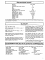
SPECIFICATION
CHART
Model No.
Horsepower
Displacement CFM at Max. Pressure
Bore
Stroke
J
919.175261
6
15
2 7/8
2"
220
20 amp
Fusetron Type "T"
15
Voltage - Single Phase
Minimum Branch Circuit Requirement
• Fuse Type
Amperage at Max. Pressure
Air Tank Capacity - Gallons
Approximate Cut-in Pressure
Approximate Cut-out Pressure
SCFM @!25 psig
SCFM @ 90 psig
SCFM @ 40 psig
UL Usted
60 gal ASME
100 psig
125 psig
9.2
10.2
12.5
Yes
• A circuit breaker is preferred. Use only a fuse or circuit breaker that is the same rating as the branch circuit
the air compressor is operated on.
i
I
GLOSSARY
CFM: Cubic feet per minute.
SCFM: Standard cubic feet per minute;
measure of air delivery.
a unit of
PSlG: Pounds per square inch gauge; a unit of
measure of pressure.
ASME: American Society of Mechanical Engineers;
made, tested, inspected and registered to meet the
standards of the ASME.
UL Listed: Underwriters Laboratories; samples of
compressor outfits taken from production were submitted to UL and found to comply with their requirements for design and performance.
Cut-Out Pressure: When you turn on your air compressor and it begins to run, air pressure in the air
tank begins to build. It builds to a certain high
pressure before the motor automatically shuts off protecting your air tank from pressure higher than its
capacity. The high pressure at which the motor shuts
off is called "cut-out pressure."
Cut-In Pressure: While the motor is off, air tank
pressure drops as you continue to use your accessory. When the tank pressure drops to a certain low
level the motor will re-start automatically. The low
pressure at which the motor automatically re-starts
is called "cut-in pressure."
To Lock-Out Power: Place a lock on the line power
switch so no one else can turn on the power.
:ESSORIES FOR USE WITH SEARS AIR COMPRESSORS
The following accessories are available through the current general sales catalog or at full-line Sears stores.
•
•
•
•
•
•
•
SPRAY GUNS
BLOW GUNS
AIR CAULKING GUNS
AIR POWERED WASHER GUNS
SAND BLASTERS
AIR BRUSHES
AIR LINE FILTERS
TIRE AIR CHUCKS
•
•
•
•
PAINT TANKS
AIR TANKS
iNFLATOR KITS
QUICK CONNECTOR SETS
(various sizes)
• VISCOSIMETER
• AIR PRESSURE REGULATORS
= OIL FOG LUBRICATORS
• AiR TOOLS
Sanders
Drills
Impact Wrenches
Hammers
® AiR HOSE:
1/4", 5t16" OR 3/8" I.D.
in various lengths
Youhavepurchasedan air
compressor unit consist*
ing of a 2 cy!inder, single stage air compressor pump,
an ASME air tank, associated controls and instruments. This air compressor
must be permanently
mounted in place.
spraying weed killers, insecticides, etc. An air prassure regulator is usually necessary for most of these
applications. Regulators can be purchased from most
Sears stores or through the Sears General Catalog or
Power Toot Catalog.
Your aircompressor can be used foroperatingpaint
spray guns, air tooJs, cauJking guns, grease guns, air
brushes, eandblasterso inflating tires and pJastio toys,
Separate airtransformerswhich combine the functions of sir regulation and/or moisture and dirt
removat should be used where applicable.
Air Compressor Pump: To compress air, the pistons
move up and down in the cy!inders.
On the
downstroke,
air is drawn in through the air intake
filter and then through the air intake valves. The
exhaust vatve remains closed. On the upstroke of the
piston, air is compressed. The intake valves close and
compressed airis forced out through the exhaust
valve, through the outlet tube, through the check
valve and intothe air tank. Working air is not available
until the compressor has raised air tank pressure
above that required at the air outlet.
Pressure Switch: The pressure switch automatically
starts the motor when the air tank pressure drops
below the factory set "cut-in" pressure. It stops the
motor when the air tank pressure reaches the factory
set "cut-out"
pressure.
Check Valve: When the air compressor is operating,
the check valve is "open," allowing compressed air to
enter the air tank. When the air compressor reaches
"cut-out" pressure, the check valve "doses," eJlowing air pressure to remain inside the air tank. If the air
is not unloaded, the motor will try to start, but vviil be
unable to. The check vane allows the motor to restart freeJy.
Pressure Release Valve: The pressure release vane is
designed to automatically release compressed air
from the compressor head and the outlet tube when
the air compressor reaches "cut-out = pressure or is
shut off. ff the air is not released, the motor will try
to start but will be unable to. The pressure release
valve allows the motor to restart freely. When the
motor stops running, air will be heard escaping for a
few seconds. No air should be heard leaking when the
motor is running.
Safety Valve: ffthe pressure switch does not shut off
the air compressor at or near its cut-out pressure
setting, the safety valve will protect against high
pressure by "popping out" at its factory set pressure
(slighdy higher than the pressure switch cut-out
setting).
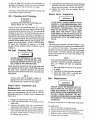
Location of the Air Compressor
Operate the air compressor in a clean, dry and we]]
ventilated area. The air intake filter must be kept dear
of obstructions which couJd reduce air delive_ of the
aircompressor.The aircompressor shouldbe located
at least 12" away from wales or other obstructions
that could interfere with the flow of air through the
fan bladed flywheel The air compressor crankcase
and head are designed wi_h fins to provide proper
cooling. If humidity is high, a Sears sir filter can be
installed on the air outlet adapter to remove excessive moisture.
The air compressor shouJd be as near to air outlets
es
possible in order to avoid long pipe lines. Do not place
the air compressor where heat is excessive.
INSTALLATION
AND
BREAK-IN
PROCEDURES
{Cont.)
to be lower than 3/8"
EXCESSIVE VIBRATION MAY WEAKEN THE
AIR TANK AND CAUSE AN EXPLOSION.
THE OUTFIT MUST BE MOUNTED AS DESCRIBED AND ILLUSTF_TED BELOW.
- 6 threads down - from the
top.) When filling the crankcase, the oil flows very
slowly. If the oH is added too quickly, it will overflow
and appear to be full. (Crankcase oil capaciW is 16
fluid ounces.) Under winter-type conditions use SAE
10W oil IMulti-viscoeity
oi! = 10W30 - will leave
carbon deposits on critical components reducing
performance and compressor life.) Replace oil fill
plug.
Wiring
instructions
iMPROPER GROUNDING CAN RESULT iN
ELECTRICAL SHOCK. WIRING OF THE PRESSURE SWITCH, ELECTRIC MOTOR AND
MANUAL ONIOFF SWITCH SHOULD BE
DONE BY A LICENSED ELECTRICIAN IN
ACCORDANCE WiTH NATIONAL AND LOCAL CODES AND ORDINANCES.
I. The air compressor must be bolted to the floor.
Bolting holes are provided in the base feet.
2. Mount the air compressor on a solid level foundation with no strain to the air tank feet° Solid
shims may be used if necessary.
Piping
Plastic or PVC pipe is not designed for use
with compressed air. Regardless of its indicated pressure rating, plastic pipe can burst
from air pressure. Use only metal pips for air
distribution lines.
If a pipe line is necessary, use pipe that is the same
size as the air tank valve. Piping that is too small will
restrict the flow of air. if piping is over 100 feet tong,
use the next larger size. Bury underground lines
below the frost line and avoid pockets where condensation can gather and freeze. Apply pressure before
underground lines are covered to make sure aU pipe
joints are free of leaks.
Lubrication
and Oil
To prevent added current draw and motor overheating we recommend the use of 12 gauge (AWG) wire,
not exceeding a 70 foot length. The wire must be
rated at a minimum temperature of 75 ° C.
When connecting wires, make sure that: (1) the
electrical box is large enough; (2) service is of
adequate amperage rating; (3} the supply line has the
same electrical characteristics (voltage, eycies and
phase} as the motor; {4) the line wire is the proper size
and (5) no other equipment is operated from the same
line. Various national and local codes and standards
have been set up covering electrica! apparatus and
wiring. These shoumd be consulted and observed. Our
recommended wire sizes may be smaller than the
minimum set up by local ordinances. If so, the larger
size wire shoutd be used to prevent excessive line
voltage drop. For wiring instructions, see the diagram
inside the pressure switch cover,
,/
WALLMOUNTED
JUNCTIONBOX
OP,DISCONNECT
..
_
CONDUIT
ELEOW
Compressors are shipped without oil Do not
attempt to operate this air compressor without first adding oil to the crankcase.
Place unit on a level surface. Remove oil fin plug and
slowly add a special compressor oit such as Sears 9 o
18428 or SAE-20-20W SF motor oil until it is even
with the top of the oil fin hole. (It must not be allowed
E_ectricaJwiring m_st bs _ocsted away from
hot s_faces such as the compressor head,
compressor cylinder or compressor outlet
tube°
Break-in
Procedures
Serious damage may resuJt if the following
break-in instructions are not closely followed,
This procedure is required only once; before the air
compressor is put into service.
1. Recheck compressor wiring, Make sure wires
are secure at all terminal connections. Free all
contacts of loose wire cuttings, etco
2. Check oil level in the crankcase before operation.
The oil level should be even with the top of the
fill hole and must not be allowed to be lower than
3/8" (six threads down) from the top at any time.
Add oil if level is low.
3. Open the outlet valve fully, to permit air to
escape and to prevent pressure build-up in the air
tank.
I
OPERATING
4. Turn ON the air compressor,
5. Run the air compressor for 30 minutes to seal the
rings and lubricate all internal surfaces,
8, Check all air line fittings and connections!piping
for air leaks by applying e soap solution. Correct
as necessary. Even minor leaks can cause this air
compressor to overwork, resulting in premature
break_down or inadequate performance.
7. Check for excessive vibration and noise. Adjust
air compressor belt guard as necessary to eliminate chatter. Re-adjust or shim the air compressor feet, if necessary for proper level.
8. Close the outlet valve and let the air compressor
pump up to cut-out pressure. Turn the air compressor off and check oil level. Add oil if necessary. Connect the air hose to the air outlet
adapter.
Your
WARNING
ready
for use.
Compressed air from the outfit may contain
water condensation end oil mist. Do not spray
unfiltered air at an item that could be damaged, Some air operated tools or devices may
require filtered air. Read the instructions for
the air tool or device.
I
TOO MUCH AIR PRESSURE CAUSES A
HAZARDOUS RISK OF BURSTING. CHECK
THE MANUFACTURER'S MAXIMUM PRESSURE RATING FOR AIR TOOLS AND ACCESSORIES. THE REGULATOR OUTLET
PRESSURE MUST NEVER EXCEED THE
MAXIMUM PRESSURE RATING.
is now
PROCEDURES
1. Before attaching an air hose or accessory, make
sure the Globe Valve OFF/AUTO lever is in the
"OFF" position.
2. Attach hose and accessory.
I
compressor
3. Turn the compressor on and allow tank pressure
to build. The motor will stop when tank pressure
reaches cut-out pressure.
Your outfit is ready for use.
UNIT CYCLES AUTOMATICALLY WHEN POWER IS ON. WHEN DOING MAINTENANCE, YOU
MAY BE EXPOSED TO VOLTAGE SOURCES, COMPRESSED AiR OR MOVING PARTS.
PERSONAL INJURIES CAN OCCUR. BEFORE PERFORMING MAINTENANCE OR REPAIR, TURN
OFF AND LOCK OUT ELECTRIC POWER AND BLEED OFF AIR TANK PRESSURE. NEVER
OPERATE THE COMPRESSOR WITH THE BELT GUARD REMOVED.
Air Compressor
A clean air compressor runs cooler and provides
longer service. Clean or blow off fins and any other
parts of the air compressor that collect dust or dirt.
Do not place rags, containers or other material on or
against the ventilation openings in the belt guard.
Adequate ventilation is necessary to maintain proper
air compressor operating temperature.
Air
Filter
- inspection
and
Replacement
NOTE
Keep the air filter dean et all times, Do not
operate the compressor with the air fiber
removed.
A dirty air filter wilt not aJtow the compressor to
operate at fuji capacity. Before you use the compressor, check the air fiiter to be sure it is clean.
If it is dirty, remove the screws and filter retainer, Pull
out the filter, replace with new.
5. ApptyseaJanttothecheckvatvethreads,Reinstai]
the check valve (turn ciockwise)o The vaJve stem
shouldetil_
move freely -do not over tighten,
6o BepJace the outlettube and tightentop and
bottom nuts,
Safety Valve = inspection
Oil - Checking
and Changing
iF THE SAFETY VALVE DOES NOT WORK
PROPERLY OVER-PRESSURIZATION
MAY
OCCUR, CAUSING AIR TANK RUPTURE OR
EXPLOSION.
OCCASIONALLY
PULL THE
RING ON THE SAFETY VALVE TO MAKE
SURE THAT THE SAFETY VALVE OPERATES FREELY. IF THE VALVE IS STUCK OR
DOES NOT OPEP_ATE SMOOTHLY, IT MUST
BE REPLACED WITH THE SAME TYPE OF
VALVE.
Overfilling with oiJ wUl cause premature compressor failure. Do no_ overfill.
Check oi_ level in the crankcase deiJy. The oit level
should be even with the top of the fill hole and must
not be allowed to' be lower than 3/8" from the top (6
threads) at any time. Jt is recommended that the oil
be changed after every 100 hours of operation. To
drain the oii, remove the oiJ drain pJug and collect the
oil in a suitable container. Be sure to replace the plug
securely before adding new oil Use a speciaJ compressor oil such as Sears 9-16426 or SAE-20-20W
SF motor oil (Crankcase oil capacity is 16 fluid
ounces.) Under extreme winter conditions use 10
weight oil.
Air Tank
= Draining
[
Water
WARNING
"_
Motor
The motor has a thermal overload protector. If the
motor overheats for any reason, the overload protector will shut off the motor. The motor must be
allowed to cooldown before restarting. De-energize
power supply. To restart, depress the reset button
located on the end of the motor and energize the
power supply.
NOTE
WATER WILL CONDENSE IN THE AiR TANK.
IF NOT DRAINED, THE WATER WILL COBRODE AND WEAKEN THE AIR TANK CAUSING A RISK OF AIR TANK RUPTURE.
If the overload protector shuts the motor off
frequently, check for a possible voltage problem. Low voltage can also be suspected
when:
Water should be drained from the air tank after each
use. Operate the unit to apply 15-20 PSIG and open
the drain cock. Continue operating unit until all
moisture is removed from the air tank. Close the drain
cock tightly.
!.
the motor does not get up to full power
or speed;
2. fuses blow out when the motor is started;
3. lights dim when motor is started and
remain dim while it is running.
NOTE
If drain cock valve is clogged, release air
pressure in air tank. The drain cock vaive can
then be removed, cleaned and reinstalled.
Belt
Check Valve - inspection and
SERIOUS INJURY OR DAMAGE MAY OCCUR IF PARTS OF THE BODY OR LOOSE
ITEMS GET CAUGHT iN MOVING PARTS.
NEVER OPERATE THE COMPRESSOR WITH
THE BELT GUARD REMOVED. THE BELT
GUARD SHOULD BE REMOVED ONLY WHEN
THE POWER TO THE COMPRESSOR iS DISCONNECTED.
Replacement
Remove the check valve for inspection or replacement if air tank pressure wifl not buitd up. Use the
following procedure to inspect, clean or replace the
check valve,
1. Release air pressure from the air tank.
2. Loosen the top and bottom nuts and remove the
outlettube.
3. Unscrew the check valve (turncounterclockwise)using a 7/8" diameter 1/2" socket wrench.
4. Check that the valve disc moves freely inside the
check valve and that the spring holds the disc in
the upper, cJosed position. The check valve may
be cleaned with a solvent.
- Replacement
The motor is mounted
on an adjustable
motor base.
To reptace belt:
1. Turn off and lock out power source.
2.
3.
4.
5.
Remove screws from the back of the belt guard.
Loosen the four motor mounting screws,
Slide the motor toward the compressor pump.
Remove belt and replace.
9
NOTE
Pulley and Flywheel
The belt should be centered over the grooves
on the flywheel and motor pulley.
6. Push the motor back into regular position and
tighten bolts securely. Proper tension is approximately 114" belt deflection measured midway
between the pulley and flywheel when a 3 pound
weight or equivalent finger pressure is applied at
this point. A loose belt will squeal at compressor
start-up.
7. Replace beltguard and screws.
I
- Alignment
The compressor flywheel and motor pulley must be
inline (in the same plane) within 1tl 6" to assure belt
retention within sheave grooves. The motor mounting holes on the saddle are skewed to square the
motor with the compressor mounting hole as the belt
is tensioned. To check alignment, disconnect electrical power and remove the belt guard. Place a straightedge against the outside of the flywheel and measure
the distance from it to the nearest groove. Alignment
is achieved when the other end of the straightedge is
within 1/16" of the measured dimension at the pulley
grooves. Squareness is achieved when the pulley
grooves are an equal distance from the straightedge
on both sides of the motor shaft.
TROUBLESHOOTING
WARNING
I
GUIDE
I
UNIT CYCLES AUTOMATICALLY WHEN POWER IS ON. WHEN DOING MAINTENANCE, YOU
MAY BE EXPOSED TO VOLTAGE SOURCES, COMPRESSED AIR OR MOVING PARTS.
PERSONAL INJURIES CAN OCCUR. BEFORE PERFORMING MAINTENANCE OR REPAIR, TURN
OFF AND LOCK OUT ELECTRIC POWER AND BLEED OFF AIR TANK PRESSURE. NEVER
OPERATE THE COMPRESSOR WITH THE BELT GUARD REMOVED.
PROBLEM
CAUSE
CORRECTION
Excessivetank pressure-safety
valve pops off.
Pressure switch does not shut off motor
when compressor reaches "cut-out" pressure.
Pressure switch must be replaced.
Air leaks at fittings
Tubeorhosefittingsarenottightenough.
Tighten fittings where air can be heard escaping.
Check fittings under soapy water solution. DO
NOT OVER-TIGHTEN.
Air leaks at check valve.
Defective or dirty check valve.
Removeand clean or replacecheckvalve. DO NOT
OVER-TIGHTEN.
Air leaks at pressure switch
release valve.
Defective pressure switch release valve.
Remove and replace the release valve.
Air leaks at air tank welds.
Defective
Air tank must be replaced.
or hose.
air tank.
o,,,,.
WISE MODIFY AIR TANK. IT WILL BE
WEAKENED.
Air leak from safety valve.
Possible defect
in safety
Operate safety valve manually be pullingon ring.
If valve still leaks, it shouldbe replaced.
Restricted check valve.
Remove and clean or replace.
Loose pulley.
Tighten pulley set screw.
Low oil level.
Maintain prescribedoil level.
Loose flywheel.
Loose compressor
10
valve.
Tighten screw.
bolts.
Check bolts. Tighten as required,
Loose belt.
Tighten belt as per instructions under Belt Re)lacement above.
Carbon build-up.
Remove the head and valve plate. Cleanthe valve
)late and the top of the piston. (Be sure carbon
does not fall into the cylinder.) Reassemble to 2530 ftJbs, using new gasket and torque screws,
PROBLEM
Motor will not run.
CORRECTION
CAUSE
Motor overload protection switch has tripped.
Let the motor cool off and reset switch by pressing
the red button located on the end of the motor.
Tank pressure exceeds pressure switch "cutin" pressure.
Motor will start automatically when tank pressure
drops below "cut-in" pressure of pressure switch.
Check valve stuck - fails to relieve
}ressure; motor cannot start.
Remove and clean or replace. (Do not overtighten,}
Loose electrical
head
connections.
Check wiring connection
and terminal box area,
inside pressure switch
Possible defective
capacitor.
Return to Sears Service Center for inspection or
replacement if necessary.
Possible defective
motor,
Have checked
Fuse blown, circuit breaker tripped.
at a local Sears Service Center.
1. Check fuse box for blown fuse and replace if
necessary. Re-set circuit breaker. Do not use
a fuse or circuit breaker with higher rating
than that specified for your particular branch
circuit.
2. Check for proper fuse; only "Fusetron" Type
T fuses are acceptable.
3. Check for low voltage conditions.
4. Remove check valve and clean or replace if it
is stuck open or closed.
5. Disconnect the other electrical appliances
from circuit or operate the compressor on its
own branch circuit.
Pressure release valve on pressure switch
has not unloaded head pressure.
Bleed the line by pushing the lever on the pressure
switch to the "OFF _ position, opening the pressure release valve. If the valve still doesn't open,
it must be replaced.
Restricted air intake.
Dirty air filter.
Replace with new.
Compressor is not supplying enough air to operate
accessories.
Prolonged excessive use of air.
Decrease amount of air usage.
Compressor is not large enough for air requirement.
Check the accessory air requirement. If it is higher
than the pressure sup plied by your air compressor,
you need a larger compressor.
Restricted
Replace air intake filter.
Excessive belt wear.
Squealing sound.
air intake filter.
Loose belt.
Adjust belt tension.
Hole in hose.
Check and replace if required.
Check valve restricted.
Remove and clean or replace.
Air leaks,
Tighten fittings. (See Air Leaks Section of Troubleshooting Guide.)
Loose belt.
Adiust tension,
Tight
Adjust tension.
belt.
Loose
pulley.
Check for worn keyway or pulley bore. Also check
for bent motor shaft. Replace parts if necessary.
Loose
belt.
Adjust
There is no oiJ in the compressor.
belt tension.
Add oil.
11
I
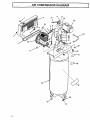
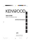
AIR COMPRESSOR
10
,I
DIAGRAM
11
12
13
15
24
36
42
17
%,
,%
%
35
_f.26
34
12
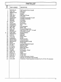
•
KEY
NO,
PARTNUMBER
t
2
3
4
5
6
7
8
9
10
11
12
13
14
15
t6
17
18
19
2O
21
22
23
24
25
26
27
29
3O
31
32
34
35
36
37
38
39
40
41
42
SSF=953_ZN
CAC_22ol
SSF=S113=ZN
CACo2
CAC_362-1
SSP=9401
STD575026
SSP-7811
SS=8553
C_BTo224
SS=391
C-PU-2868
STD5801 {)4
CACo4205
MO=70Sl
CACo1331
SSF-928
SS-65{)6_CD
CAC-4336
SS-3222oCD
CAC-95
T1A-4159
C-GA-346
SSFo995oZN
SSF=8110=ZN
SS-1525-CD
SSV=5
SSF=815{)
CL-159
LA-1848=1
LA=I B11-1
SS-2707
TA-4259
SSW-7367
SSPo211 {)
CAC-437o2
CAC=357=1
SSFo3152
LA=1779
CAC=4{)29
DESCRIPTION
Sell' Tapping Screw (4 used)
Be_ Guard
Lock Nut
Bracket
Be_ Gua_ C_osure
Connector
Nut-SleeveAssembly {2 used)
Nut Sleeve Assembly
Connector
PolyoV Belt
Set Screw
Motor Putley
Key
Cord Assembly
Motor S HP
Pressure Release Tube
Cap Screw 5/t6'°=1B=1" (4 used)
Fla_washer {4 used)
Pressure Switch
Pipe Plug
Man,old
Safe_J Valve
Gauge
Screw (2 used)
Locknut (4 used)
Isolator
Washer {4 used)
Globe Valve
Locking Flange Nut (4 used)
Model No. Label
Warning Label
Sears Logo Label
D_in Valve
Air Receiver o 6{) gel
Strain Relief
Nippie
Check Valve
OutletTube
Locking Cap Screw (4 used)
Warning - Hot Su_ace Label (2 used)
Compressor Pump Assembly {includes
Key Nee 43 thru 78, inclusive)
13
I
!
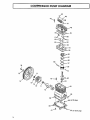
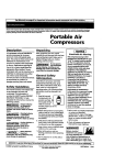
COMPRESSOR PUMP DIAGRAM
/44
45
.
48
5
9
66 (oil fill plug)
I
68
66 (oil drain p_ug)
14
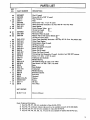
PARTS LiST
ram--
KEY
NO.
e
=
[]
[]
*
+
+
+
e
*
PART NUMBER
DESCRIPTION
43
44
45
46
47
48
49
50
SSF-6627
SSF-935
265_18
265-17
SSF-955
CAC-4213
CAC-291
265-25
51
52
53
SSF-9821
CAC-294
265-196
54
55
56
57
58
59
60
61
62
63
64
65
66
67
68
69
7O
71
72
73
74
75
76
77
78
CAC-4212
CAC-54-1
CAC-56-1
CAC-58
CAC-57
CAC-55-1
265-19
CAC-207
265-410
SSF-927
CAC-51
265-41
SSP-1413
SSF-925
265-3
265-16
CAC-373
265-23
265-13
265-9
265-2
SSN-1014-ZN
STD541437
265-111
265-6
Stud (2 used)
Screw #8-32 x 318" (2 used}
Filter Retainer
Filter
Screw 3/8"-16 x 1o112" (4 used)
Head Assembly (includes 2 ea. Key #50 & 4 ea. Key #51)
Head Gasket
intake Rapper Valve
(2 used on head)
Screw (8 used)
Restdctor Plate (2 used)
Rapper Valve with Comer Bevels
(2 used on valve plata)
Valve Plats Assembly (includes 4 eao Key #51 & 2 ea. Key #52 & 53)
Valve Plate Gasket
Compression Ring (4 used)
Oil Ring (4 used}
Oil Ring Expander {2 used)
Piston {2 used)
Piston Pin (2 used}
Piston Pin Plug (4 used)
Connecting Rod Assembly (2 used), includes two SSF-927 screws.
Screw 1/4"-20 x 1-1/8" 14 used)
Crankcase and Cytinder
Needle Bearing
Oil Fill/Drain Plug (2 used) (1/4" NPT)
Cap Screw 1/4"-20 x 718" {12 used)
Base
Base Gasket
Crankshaft
Needle Bearing
End Plate Gasket
End Plate
Rywheel
Washer
Screw
Oil Seal
Vent Filter
NOT SHOWN
SI-30-11 4-A
Owners
Manual
Parts Ordering information
_F Key No= 56,
® Key No. 19,
m Key No. 50,
Key NOo 4.6,
57, 58 enly available in Ring Kit KK_313.
pressure release valve and nut is available as pa_ of Kit KK-5020.
51 and 53 onty available in Valve Kit KK-4275.
49, 55, 69, 72, 77 and 78 are available in Gasket Kit KK-4312-2.
15
SF_ S
OWNERS
MANUAL
ONE STAGE
AIR COMPRESSOR
SERVICE
Now that you have purchased your Sears Air Compressor,
should a need ever exist for repair parts or service, simply
contact any Sears Service Center and most Sears, Canada,
Inc. stores. Be sure to provide all pertinent facts when you
call or visit.
MODEL NO.
The model number can be found on the label which is
located on the front of the air tank saddle.
HOW TO ORDER
REPAIR PARTS
WHEN ORDERING REPAIR PARTS, ALWAYS
FOLLOWING INFORMATION:
GIVE THE
• PART NUMBER
• PART DESCRIPTION
• MODEL NUMBER
• NAME OF ITEM
If service or repair parts are required for the motor, supply
all motor nameplate information including manufacturer's
name.
All parts listed may be ordered from any Sears Service
Center and most Sears stores.
If the parts you need are not stocked locally, your order
will be electronically transmitted to a Sears Repair Parts
Distribution Center for handling.
Sears,
SI-30-11-4-A
8/921
Roebuck
and Co., Chicago,
IL 60684
U.S.A.
PrintedinU.S.A.