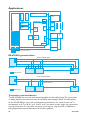
1
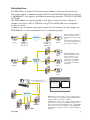
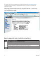
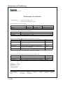
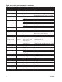
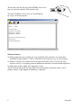
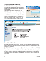
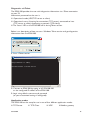
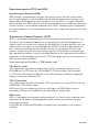
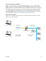
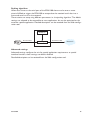
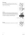
6616-2202
EDW-100
Serial Adapter
www.westermo.com
© Westermo Teleindustri AB • 2007
User Guide
Safety
!
Before installation:
Read this manual completely and gather all information on the unit. Make sure
that you understand it fully. Check that your application does not exceed the safe
operating specifications for this unit.
This unit should only be installed by qualified personnel.
This unit should be built-in to an apparatus cabinet, or similar, where access is
restricted to service personnel only.
The power supply wiring must be sufficiently fused, and if necessary it must be
possible to disconnect manually from the power supply. Ensure compliance to
national installation regulations.
This unit uses convection cooling. To avoid obstructing the airflow around the unit,
follow the spacing recommendations (see Cooling section).
!
Before mounting, using or removing this unit:
Prevent access to hazardous voltage by disconnecting the unit from power supply
and all other electrical connections.
Warning! Do not open connected unit. Hazardous voltage may occur within
this unit when connected to power supply or TNV circuits.
Maintenance
No maintenance is required, as long as the unit is used as intended within the specified
conditions.
2
6616-2202
Introduction
The EDW-100 is an Industrial Ethernet to serial adapter or Ethernet Terminal Server.
The serial interface is selectable between RS-232 and RS-422/485. The Ethernet interface
is 10/100BASE-T and supports the following networking protocols: TCP, UDP, ICMP, IGMP,
HTTP, ARP.
Two EDW-100 can be used to provide a serial point to point link over an Ethernet
network using either UDP or TCP. When using TCP the EDW-100 can be configured
as client or server.
In addition to a transparent serial point-to-point link and ethernet to serial adapter, the
EDW-100 MG can also be configured to act as a Modbus gateway.
Network
Serial
Device
Configured
as UDP- or
TCP-server
Configured
as UDP- or
TCP-client
Serial
Device
Serial
Slave
Network
Broadcast
Multicast
Serial
Slave
Serial
Master
Each unit passes data from
its serial interface to the
serial interface of the other
unit.
This enables long distance
serial communication using
pre-existing networks.
When EDW-100 is used
with the UDP protocol it
is also possible to communicate one to many
(e.g. master to multiple
slaves), by using a broadcast address or multicast
addressing
Serial
Slave
Network Interface
Application software
COM port
redirector software
Data to / from COM3
Data to / from COM4
Data to / from COM5
Data to / from COM255
Network
COM3
COM255
COM4
6616-2202
COM5
EDW-100 can also provide a remote serial interface
for a computer connected through a TCP/IP network
using a comport redirection software.
A COM port redirector or customer written software
can be used to create virtual COM ports. This software will redirect data, originally sent to a local COM
port, to the remote serial interface of the EDW-100.
No changes are required on the computer application
software.
3
For more information on applications and technical data visit www.westermo.com.
The Web tool also includes an integrated help where all functions and modes are
described in details.
More help can be found inside the web tool and the "?" button on
each configuration page.
Agency approvals and standards compliance
Type
EMC
Safety
4
Approval / Compliance
EN 61000-6-2, Immunity industrial environments
EN 61000-6-4, Emission industrial environments
EN 55024, Immunity IT equipment
EN 50121-4, Railway signalling and telecommunications apparatus
IEC 62236-4, Railway signalling and telecommunications apparatus
EN 60950, IT equipment
6616-2202
Declaration of Conformity
Westermo Teleindustri AB
Declaration of conformity
The manufacturer
Westermo Teleindustri AB
SE-640 40 Stora Sundby, Sweden
Herewith declares that the product(s)
Type of product
Model
Art no
Installation manual
DIN-rail
DIN-rail
EDW-100
EDW-120
3616-0020
3616-0010
4500-0112, 6616-2011
4500-0112, 6616-2221
is in conformity with the following EC directive(s).
No
Short name
89/336/EEG
73/23/EEG
Electromagnetic Compatibility (EMC)
Low Voltage Directive - LVD
References of standards applied for this EC declaration of conformity.
No
Title
Issue
EN 61000-6-2
EN 61000-6-1
Immunity for industrial environments
Immunity for residential, commercial and lightindustrial environments
Information technology equipment – Immunity
Emission standard for residential, commercial and
light-industrial environments
Safety of information technology equipment
2 (2001)
1 (2001)
EN 55024
EN 61000-6-3
EN 60950
The last two digits of the year in which the CE marking was affixed:
1 (1998)
1 (2001)
6 (2000)
06
Herewith declares that product(s) listed above is in conformity with
No
Title
Issue
FCC part 15
EN 50121-4
IEC 62236-4
Radio frequency devices
Railway signalling and telecommunications apparatus
Railway signalling and telecommunications apparatus
1 (2003)
1 (2000)
1 (2003)
Hans Levin
Technical Manager
18th April 2006
Postadress/Postal address
Tel.
Telefax
Postgiro
Bankgiro
Org.nr/
Corp. identity number
Registered office
S-640 40 Stora Sundby
016-428000
016-428001
52 72 79-4
5671-5550
556361-2604
Eskilstuna
Sweden
Int+46 16428000
Int+46 16428001
6616-2202
5
Type tests and environmental conditions
Electromagnetic Compatibility
Phenomena
Test
ESD
EN 61000-4-2
RF field AM
modulated
IEC 61000-4-3
RF field 900 MHz
Fast transient
ENV 50204
EN 61000-4-4
Surge
EN 61000-4-5
RF conducted
EN 61000-4-6
Power frequency
magnetic field
Pulse magnetic field
Voltage dips
and interruption
EN 61000-4-8
Test levels
± 6 kV
± 8 kV
10 V/m 80% AM (1 kHz), 80 – 1 000 MHz
20 V/m 80% AM (1 kHz), 800 – 960 MHz
20 V/m 80% AM (1 kHz), 1 400 – 2 000 MHz
Enclosure
20 V/m pulse modulated 200 Hz, 900 ± 5 MHz
Signal ports
± 2 kV
Power ports
± 2 kV
Signal ports unbalanced ± 2 kV line to earth, ± 2 kV line to line
Signal ports balanced
± 2 kV line to earth, ± 1 kV line to line
Power ports
± 2 kV line to earth, ± 2 kV line to line
Signal ports
10 V 80% AM (1 kHz), 0.15 – 80 MHz
Power ports
10 V 80% AM (1 kHz), 0.15 – 80 MHz
Enclosure
100 A/m, 50 Hz, 16.7 Hz & 0 Hz
EN 61000-4-9
EN 61000-4-11
Enclosure
AC power ports
Radiated emission
EN 55022
Conducted emission EN 55022
EN 55022
Dielectric strength
EN 60950
Environmental
Phenomena
Temperature
Test
Humidity
Enclosure
AC power ports
DC power ports
Signal port to other
isolated ports
Power port to other
isolated ports
Description
Operating
Storage & Transport
Operating
Storage & Transport
Operating
Operating
Operating
Altitude
Service life
Vibration
IEC 60068-2-6
Shock
IEC 60068-2-27 Operating
Packaging
Enclosure
UL 94
Dimension
WxHxD
Weight
Degree of protection IEC 529
Cooling
Mounting
6
Description
Enclosure contact
Enclosure air
Enclosure
PC / ABS
Enclosure
100 A/m, 6.4 / 16 ms pulse
10 & 5 000 ms, interruption
10 & 500 ms, 30% reduction
100 & 1 000 ms, 60% reduction
Class A
Class B
Class B
2 kVrms 50 Hz 1 min
3 kVrms 50 Hz 1 min
2 kVrms 50 Hz 1 min (@ rated power <60 V)
Level
–25 to +70ºC
–40 to +70ºC
5 to 95% relative humidity
5 to 95% relative humidity
2 000 m / 70 kPa
10 year
7.5 mm, 5 – 8 Hz
2 g, 8 – 500 Hz
15 g, 11 ms
Flammability class V-1
35 x 121 x 121 mm
0.2 kg
IP 21
Convection
On 35 mm DIN-rail
6616-2202
Product description
The EDW-100 is an industrial Ethernet to serial interface adapter designed for harsh
environments.
It allows serial devices to interface through a new or existing Ethernet network. The unit
can support either RS-232, RS-485 or RS-422 based protocols running at up to 115.2
kbit/s. Ethernet connection is via a standard RJ-45 port with MDI/MDI-X.
The protocols used for network communication is UDP or TCP. This allows the EDW100 to be setup as a TCP-server or -client as well as an UDP unit.
Configuration of the unit
The EDW-100 can be easly configured via the onboard Web based configuration tool,
alternatively some functions can also be set by hardware DIP-switches on the PCB.
The network interface properties such as speed, duplex and auto-negotiation can be
configured by the Web based configuration tool or by hardware DIP-switches.
It is also possible to monitor and override the hardware settings by using the Web tool, if
that is done this is indicated by the RC LED (Remotely Controlled).
The serial port properties such as data rate, flow control and data bits etc. are configured by the Web based configuration tool.
6616-2202
7
Termination and fail-safe of the RS-422/485 serial interface can only be made by DIP-switches only.
The local IP address of the unit can be configured
by using a terminal program.
New Connection - Hyper Terminal
File
Edit
View
Call
Transfer
Help
'EDW-100 IP CONFIGURATION'
Firmware
: 4100-9002
-- Current IP configuration -Local IP address : 169.254.100.100
Gateway address : 169.254.100.1
Subnet Mask address : 255.255.255.0
Press <Return> to select the value shown in braces,
or enter a new value.
Local IP address [169.254.100.100]?
Connected 0:01:33
VT100
9600 8-N-1
SCROLL
CAPS
NUM
Capture
Print echo
Unique features
… Packing algorithm that enables the user to decide how and when the serial data
should be encapsulated in a TCP or UDP data frame and sent out on the network.
… Galvanic isolation, this feature eliminate communication errors. One of the most
common errors is caused by potential differences between interconnected equipment.
… Redundant power supply with wide input range.
Theses feature along with the high EMC immunity enables the device to be used in
projects where a high degree of reliability is required.
8
6616-2202
Diagnostic information
The first level of diagnostic information is the status indicated by the LED´s.
C:\WINDOWS\System32\telnet.exe
Westermo EDW-100
login: edw100
Password: ******
Hello edw100
Welcome to Westermo EDW-100 diagnostics service
(TCP Server): Listening for TCP connection on port: [9000]...
The Telnet diagnostic service provide the user with information
such as UDP- or TCP mode, connected or listening state (TCP) etc.
6616-2202
9
Getting started
IP Address
The default IP address of the EDW-100 when delivered is 169.254.100.100.
Default port 9000
Default gateway 169.254.100.1
IP address configuration
The IP address is configurable by the Web tool and/or by using a terminal program.
Below is an description of how to configure the IP address by using a terminal program.
1. If the address is known, connect the unit from a Web browser with the address to
EDW-100. If the address is unknown, connect the serial RS-232 interface to a terminal
program with settings:
EDW-100
Computer
DTE
DTE
Data rate:
9600 bit/s
Data bits:
8
3
3
2
2
Stop bits:
1
7
7
Parity:
None
8
8
6
6
Flow control: None
5
5
Note! When connecting EDW-100 to a Comport in a
1
1
4
4
computer you have to use a “Cross-over” cable,
9
9
because both EDW-100 and the computer
interface is DTE. 1.8 m standard cable is supported by Westermo art.no.
1211-2172.
2. Setting DIP S1:1 to ‘On’ and power-up the EDW-100 will enable the local IP address
to be configured via serial interface.
Once connected with the terminal program you can change the IP address, Gateway
address and Subnet Mask according to the picture below:
New Connection - Hyper Terminal
File
Edit
View
Call
Transfer
Help
'EDW-100 IP CONFIGURATION'
Firmware
: 4100-9002
-- Current IP configuration -Local IP address : 169.254.100.100
Gateway address : 169.254.100.1
Subnet Mask address : 255.255.255.0
Press <Return> to select the value shown in braces,
or enter a new value.
Local IP address [169.254.100.100]?
Connected 0:01:33
VT100
9600 8-N-1
SCROLL
CAPS
NUM
Capture
Print echo
See also configuration by
Web Tool on page 14
3. Set DIP S1:1 to ‘Off’ and power cycle the EDW-100.
4. The unit is now ready for a complete configuration by the Web tool.
Address EDW-100 in a browser with the configured IP address.
Note that the used computer have to be on the same
10
6616-2202
Username and Password for configuration
The EDW-100 is username and password protected. These are used when connecting
with Web browser during configuration and with Telnet for diagnostics.
Default username: edw100
Default password: edw100
Browser Login
The Webtool has two different login accounts.
The first is the EDW-100 Guest account that only allows the user to read the units settings but he has no rights to configure the unit in any way. This accounts Username and
Password are fixed and aren’t configurable.
EDW-100 Guest
Username: guest
Password: guest
or
Username: anonymous
Password: anonymous
EDW-100 Config
The second account is the EDW-100 Config that gives the user rights to configure the
unit with new parameter values. This accounts Username and Password can also be configured when the user are logged in as EDW-100 Config. Default Username and Password
are listed below.
Default Username: edw100
Default Password: edw100
Restore Factory default settings
Note! This will clear your customized settings.
ON
The factory default settings can be restored using DIP-switch S1:2.
1 2 3 4 5 6 7 8
1. Force this to ‘On’ and Power-up the EDW-100 for at least 5 seconds.
2. Force the DIP-switch to ‘Off’ and power cycle the EDW-100.
The EDW-100 now contains the factory default settings.
Note ! If the default address of the unit is valid on the connected network it is possible
to access the unit directly from a browser.
6616-2202
11
Configuration by Web Tool
The EDW-100 includes an easy-to-use Web configuration tool. The Web tool is very intuitive and
includes useful help information for the configurable parameters.
Connect and login to the EDW-100 with the
EDW-100 Config account on the default IP address
and with default username- and password combination (or your customized if configured) using a
standard Web browser.
Use the Configuration Wizard to set all parameters then press the button "Program Unit" to
write the parameters into the unit or save the
Serial/IP® and Telnet Options
EDW-100 are bundled with Serial/IP® avertual Com port director software. The Serial/
IP® use portions of the “Telnet Environment Option” (RFC1572) to verify that it is connected to an EDW-100.
The EDW-100 has partial support for the “Telnet Com Port Control Option” (RFC2217).
This makes it possible to remotely (on the fly) change serial port parameters. Currently
supported parameters are baud rate, parity, number of data bits and number of stop bits.
As default the Telnet Options are disabled. If the Serial/IP® software is to be used, the
Telnet options must med enabled in the web tool. This parameter can be found on the
serial page.
12
6616-2202
Diagnostics via Telnet
The EDW-100 provides the user with diagnostics information via a Telnet connection
on port 23.
Information presented to the user is:
… Operational mode (UDP, TCP-server or client)
… Operational status (Listening for connection (TCP server), connected to host
(TCP server or client), Attempting to connect (TCP client))
… The ‘Status’ LED on the EDW-100 will lit during Telnet session.
Below is an description of how to start a Windows Telnet session and get diagnostics
information from the EDW-100.
1. Start a Telnet session.
C:\WINDOWS\System32\telnet.exe
Welcome to Microsoft Telnet Client
Escape Character is 'CTRL+]'
Microsoft Telnet> o 169.254.100.100
2. Connect to EDW-100 by typing ‘o 169.254.100.100’
or the configured IP address of the EDW-100.
3. Login using default username and password
(or your customized settings if configured).
Application modes
The EDW-100 can be setup for use in one of four different application modes:
… TCP Server
… TCP Client
… UDP
… Modbus gateway
6616-2202
13
Short description of TCP and UDP
User Datagram Protocol (UDP)
UDP provides a connectionless datagram service. This means that the arrival of datagram’s or data packets is not controlled and the reliability of the communication is the
responsibility of the application layer protocol. In this way UDP is a simpler method of
communication than TCP. As data is sent and received without any established connection
the data transfer is more efficient and often faster. UDP is therefore used in applications
that require efficient use of the bandwidth and also have a higher level protocol to handle
lost data.
Transmission Control Protocol (TCP)
TCP is a connection-oriented delivery service. Connection oriented means that a connection must be established before hosts can exchange data. An acknowledgement is
used to verify that the data was received by the other host. For data segments sent, the
receiving host must return an acknowledgement (ACK). If an ACK is not received, the
data is retransmitted. Flow-control between the hosts is managed by TCP. For larger
amounts of data that have to be split between packets TCP provides a method for reliably reassembling the data in the correct order. Because of the requirement to establish a
connection and acknowledge transmissions, TCP takes longer time to transmit data than
UDP and uses more bandwidth.
When delivered the EDW-100 is in TCP server mode.
TCP Server mode
This mode makes it possible to accept incoming TCP connections attempts to the
EDW-100 from an TCP client e.g. a EDW-100 in TCP client mode. Other examples
of TCP clients: Telnet client establishing a raw TCP connection, COM-port redirector
software running on a Windows PC.
TCP Client mode
This mode makes it possible to establish a TCP connection to a remote TCP server e.g.
a EDW-100 in TCP Server mode.
DSR signal rising or a powering up the unit will trigger the EDW-100 to make an
connection attempt to the specified server depending on configuration.
UDP mode
UDP is a connection less protocol sending datagram’s i.e. there are less overhead traffic
compared to TCP and no acknowledgement packets will be sent between the peer’s
during communication.
Using UDP will enable the EDW-100 to send and listen to broadcast- and multicast
messages.
14
6616-2202
Short description of Modbus
Modbus is a communication protocol developed by Modicon systems. The EDW-100
Modbus gateway is used for interconnecting a TCP/IP Modbus network and a serial line
Modbus network (either RTU or ASCII). It permits Modbus clients (masters) on either of
the TCP/IP or the serial network to connect to Servers (slaves) on the other network.
In a standard Modbus network, there is one master and up to 247 Slaves, each with a
unique slave address from 1 to 247. The master can also write information to the slaves.
The official Modbus specification can be found at www.modbus-ida.org.
Gateway Server mode
Allows up to 16 Modbus clients (masters) on a TCP/IP network to connect to servers
(slaves) on the serial network.
Modbus TCP Client
Modbus TCP
Modbus RTU or
Modbus ASCII
Ethernet
RS-485
Modbus Slave 1
EDW-100
Modbus Gateway
Modbus Slave 2
Modbus TCP Client
Up to 16 TCP
Clients (Master)
Up to 247 servers
(Slaves)
Modbus Slave 3
Modbus Slave 4
6616-2202
15
Gateway Client mode
Allows one Modbus client (master) on a serial network to connect to one or more servers (slaves) on the TCP/IP network.
Modbus
Slave 5
Modbus TCP
Modbus RTU or
Modbus ASCII
Ethernet
RS-485
EDW-100
Modbus gateway
Modbus Client
Modbus Slave 2
Modbus
Slave 6
Max total 247 Servers
1 Client (Master)
and up to
247 servers
(Slaves)
Modbus Slave 3
Modbus Slave 4
Setting up the EDW-100 as a Modbus Gateway
Set the EDW-100 application mode to Modbus gateway to enable the gateway functionality. Serial settings and ip-configuration is shared whit the other application mode but the
rest of the Modbus configuration is done on the specific Modbus configuration page. To
set up the gateway it is necessary to know details about the TCP and the serial Modbus
network. Please refer to the web tool help page for more configuration details.
16
6616-2202
Packing algorithm
When data arrives at the serial port of the EDW-100 there must be one or more
criteria fulfilled to trigger the EDW-100 to encapsulate the received serial data into a
frame and send it out on the network.
These criteria are setup using different parameters i.e. the ‘packing algorithm’. The default
settings are selected to be compatible to most applications but can be optimized to the
customer specific application. Detailed description can be received from the Web configuration tool.
Conditions
Received data
Transmitted data
Packing
Network
Advanced settings
Advanced settings configure the unit for special application requirements or special
interface functions, these settings are default disabled.
Detailed description can be received from the Web configuration tool.
6616-2202
17
Interface specifications
Power
Rated voltage
Operating voltage
Rated current
Rated frequency
Maximum inrush
current @ 10 ms
Polarity
Redundant power input
Isolation to
Connection
Connector size
12 to 48 VDC
10 to 60 VDC
250 mA @ 12 VDC
125 mA @ 24 VDC
63 mA @ 48 VDC
DC
0.3 A2s @ 48 VDC
Reverse polarity protected
Yes
All other 3 kVrms
Detachable screw terminal
0.2 – 2.5 mm2 (AWG 24 – 12)
RS-422/485
Electrical specification
Data rate
Data format
Protocol
Retiming
Turn around time
Circuit type
Transmission range
Settings
Protection
Isolation to
Connection
Connector size
Shielded cable
Conductive housing
EIA RS-485
2-wire or 4-wire twisted pair
300 bit/s – 115.2 kbit/s
7 or 8 data bits, Odd, even or none parity, 1 or 2 stop bits
Transparent, optimised by packing algorithm
Not applicable
< 3 bits
TNV-1
≤ 1200 m, depending on data rate and cable type (EIA RS-485)
120 Ω termination and fail-safe biasing 680 Ω
Installation Fault Tolerant (up to ±60 V)
Power 3 kV
Ethernet 1 1.5 k Vrms
Detachable screw terminal
0.2 – 2.5 mm2 (AWG 24 – 12)
Not required, except when installed in Railway applications as
signalling and telecommunications apparatus and located
close to rails*
No
* To minimise the risk of interference, a shielded cable is recommended when the cable is located inside 3 m
boundary to the rails and connected to this port.
The cable shield should be properly connected (360°) to an earthing point within 1 m from this port.
This earthing point should have a low impedance connection to the conductive enclosure of the apparatus
cabinet, or similar, where the unit is built-in. This conductive enclosure should be connected to the earthing
system of an installation and may be directly connected to the protective earth.
18
6616-2202
RS-232
Electrical specification
Data rate
Data format
Protocol
Retiming
Circuit type
Transmission range
Isolation to
Connection
Shielded cable
Conductive housing
Number of ports
EIA RS-232
300 bit/s – 115.2 kbit/s
7 or 8 data bits, Odd, even or none parity, 1 or 2 stop bits.
Transparent, optimised by packing algorithm
Not applicable
SELV
15 m
Power 3 kV
Ethernet 1 1.5 kVrms
9-pin D-sub male (DTE)
Not required, except when installed in Railway applications as
signalling and telecommunications apparatus and located close
to rails*
Isolated to all other circuits
1
Ethernet
Electrical specification
Data rate
Protocol
Duplex
Circuit type
Transmission range
Isolation to
Connection
Shielded cable
Conductive housing
IEEE std 802.3. 2000 Edition
10 Mbit/s or 100 Mbit/s, auto-negotiated or manually
set by DIP-switches
UDP, TCP, ICMP, HTTP and ARP
Full- or half duplex, auto-negotiated or manually set by DIP-switches
TNV-1
100 m
Power 3 kVrms
RS-232 1.5 kVrms
RS-422/485 1.5 kVrms
RJ-45 shielded, auto MDI/MDI-X
Not required, except when installed in Railway applications as
signalling and telecommunications apparatus and located close
to rails*
Isolated to all other circuits
* To minimise the risk of interference, a shielded cable is recommended when the cable is located inside 3 m
boundary to the rails and connected to this port.
The cable shield should be properly connected (360°) to an earthing point within 1 m from this port. This earthing point should have a low impedance connection to the conductive enclosure of the apparatus cabinet,
or similar, where the unit is built-in. This conductive enclosure should be connected to the earthing system
of an installation and may be directly connected to the protective earth.
6616-2202
19
Mounting
This unit should be mounted on 35 mm DIN-rail, which is
horizontally mounted inside an apparatus cabinet, or similar.
Snap on mounting, see figure.
CLICK!
Cooling
This unit uses convection cooling. To avoid obstructing the airflow around the unit, use the following spacing rules. Minimum
spacing 25 mm (1.0 inch) above /below and 10 mm (0.4 inches)
left /right the unit. Spacing is recommended for the use of unit
in full operating temperature range and service life.
10 mm *
(0.4 inches)
* Spacing (left/right) recommended for
full operating temperature range
25 mm
25 mm
Removal
Press down the black support at the top of the unit. See figure.
20
6616-2202
Connections
S1 DIP-switch under lid
(for details see page 21)
LED indicators, also
integrated in the RJ-45
connector.
(for details see next page)
RS-422/485 interface
screw terminal
4-position Direction*
No. 1
In
Ethernet 1
RJ-45 connection
(for details see next page)
No. 2
In
No. 3
In/Out
No. 4
In/Out
Description
R+
line RS-422
R–
line RS-422
T+
line RS-422/485
T–
line RS-422/485
* Direction relative this unit
S2 DIP-switch
Termination
(for details see page 21)
Power connection
screw terminal
4-position
No. 1
No. 2
No. 3
No. 4
RS-232 (DTE)
9-position Direction
No. 1
N/C
No. 2
In
No. 3
Out
No. 4
Out
No. 5
–
No. 6
In
No. 7
Out
No. 8
In
No. 9
N/C
6616-2202
Description
Not connected (DCD)
Received Data (RD)
Transmitted Data (TD)
Data Terminal Ready (DTR)
Signal Ground (SG)
Data Set Ready (DSR)
Request To Send (RTS)
Clear To Send (CTS)
Not connected (RI)
Description
Common
+VA
+VB
Common
The EDW-100 supports redundant power
connection. The positive input are +VA and
+VB, the negative input for both supplies are
COM. The power is drawn from the input
with the highest voltage.
21
Ethernet
Ethernet TX connection (RJ-45 connector), automatic MDI/MDI-X crossover*.
Contact
1
2
3
4
5
6
7
8
Shield
Signal Name
TD+
TD–
RD+
RD–
Direction
In/Out
In/Out
In/Out
In/Out
Description/Remark
Transmitted/Received
Transmitted/Received
Transmitted/Received
NC
NC
Transmitted/Received
NC
NC
HF-connected
data
data
data
data
8
7
6
5
4
3
2
1
CAT 5 cable is recommended.
Unshielded (UTP) or
shielded (STP) connector might be used.
* Depend of settings on S1; 6, 7 and 8.
LED Indicators
LED
PWR
Power
TD
Status
OFF
ON
OFF
Transmit data
RD
Receive data
RTS
Request to send
CTS
Clear to send
LINK
STAT
Status
RC
Remotely controlled
SPD
Speed Integrated in RJ-45
Green
DPX
Duplex Integrated in RJ-45
Yellow
22
ON
OFF
ON
OFF
ON
OFF
ON
OFF
ON
Flash
OFF
ON
OFF
ON
ON
OFF
ON
OFF
Description
No internal power
Internal Power OK
No serial data transmitted from the unit,
(RS-232 or RS-422/485)
Serial data transmitted from the unit, (RS-232 or RS-422/485)
No serial data received to the unit, (RS-232 or RS-422/485)
Serial data received to the unit, (RS-232 or RS-422/485)
No RTS to the RS-232 interface or RS-422/485 transmitting.
RTS to the RS-232 interface or RS-422/485 receiving.
No CTS from the RS-232 interface
CTS from the RS-232 interface
No Ethernet link.
Cable not connected.
Good Ethernet link.
Ethernet data is transmitted or received, traffic indication.
Normally Off
Telnet session established to Telnet diagnostics service or
Ongoing configuration by Web tool
DIP switch settings are valid.
One or more DIP switches are overrid by remote configuration
Ethernet 100 Mbit/s
Ethernet 10 Mbit/s
Full duplex
Half duplex
6616-2202
DIP-switch settings
Before DIP-switch settings:
!
Prevent damage to internal electronics from electrostatic discharges (ESD)
by discharging your body to a grounding point (e.g. use of wrist strap).
S1:8
S1:1
S1* DIP-switch
ON
ON
Normally OFF
1 2 3 4 5 6 7 8
ON
1 2 3 4 5 6 7 8
1 2 3 4 5 6 7 8
Enable local IP configure via serial
interface.
ON
ON
1 2 3 4 5 6 7 8
ON
Normally OFF
1 2 3 4 5 6 7 8
1 2 3 4 5 6 7 8
ON
ON
Restore factory default.
1 2 3 4 5 6 7 8
ON
1 2 3 4 5 6 7 8
1 2 3 4 5 6 7 8
Ethernet Auto-negotiation enabled.
Auto-crossover enabled.
10 Mbit/s.
ON
1 2 3 4 5 6 7 8
Ethernet Auto-negotiation disabled.
Auto crossover (MDI/MDIX)
disabled. 10 Mbit/s.
Ethernet 100 Mbit/s when Autonegotiation disabled
Ethernet 10 Mbit/s when Autonegotiation disabled
Ethernet Full duplex when Autonegotiation disabled or is not
supported.
Ethernet Half Duplex Auto-negotiation disabled or is not supported.
* DIP switch functions may be override by WEB configuration tool. Override is indicated by RC LED.
S1, 3, 4 and 5 not used.
Note! DIP-switch alterations are only effective after a power on.
A setting configured by any other method during normal operation, possibly
overrides the DIP-switch setting. However, an override situation is indicated
by the RC LED.
S2 Below panel
ON
1 2 3 4
ON
1 2 3 4
4-wire termination.
120 ohm 4-wire termination and fail-safe
2-wire termination.
120 ohm 2-wire termination and fail-safe
Factory settings
S1
ON
1 2 3 4 5 6 7 8
6616-2202
S2
ON
1 2 3 4
23
3.3 V = >1.5 V
DIP-switch
LED
stretch
JTAG
DEBUG
XTAL
FLASH
2 MB
MAC
Data
Address
CTRL
PHY
RJ-45
PROCESSOR
SDRAM
8 MB
Ethernet 1
Power secondary 5 V
5 V = >3.3 V
Applications
RS-232
CLK
RESET
I/O
XTAL
D-sub
Power
SERIAL CH 1
RS-422/485
I/O
Power
A
Power
B
Screw terminal
Connector
Isolation from all other interfaces
RS-422/485 general advice
4-wire termination
R+
R–
T+
T–
R– R+ T– T+ R– R+ T– T+
EDW-100
B’ A’ B
A
=Termination
Slave unit
Slave unit
Slave unit
2-wire termination
T+
T–
Max 0.3 metre
EDW-100
T- T+
T- T+
B
A
=Termination
Slave unit
Slave unit
Slave unit
Termination recommendations
The RS-422/485 line must be terminated regardless of the cable length. The termination
is ideally placed at the extreme ends of the cable see examples above. The description
of the RS-422/485 pin outs will vary between manufactures. For some brands the T+
corresponds to A T- to B, R+ to A´ and R- to B´, but other brands might use some other
naming convention. If a unit does not work it can help to swap A and B. If difficulty is
being experience contact Westermo for further guidance.
24
6616-2202
One to many using UDP using broadcast or multicast
Network
Description
The one to many function can be used in place of a traditional RS-422 or RS-485 multidrop
application. Data entering one of the EDW-100 will be broadcast or Multicast to any other
device in the broadcast or multicast group. A typical application would be a SCADA host
computer communicating to a number of PLC’s.
Point to point using TCP connection, server and client
Network
6616-2202
25
Point to point using UDP connection
Network
Description
In a point to point application the EDW-100 can be to replace or extend a cable link.
The distance between the EDW-100 units is only limited by the size of the LAN.
Data can be sent across the network using ether UDP or TCP. A typical application
would be a SCADA or Data logging application interrogating a sensor or PLC.
To understand the differences between a UDP and TCP please see page 16–17.
Communication one to many using TCP
Network
Virtual IP
IP address:port = Com X
IP address:port = Com Y
IP address:port = Com Z
Description
Many legacy software applications do not have any facilities to directly use Ethernet but there is
a requirement to use a newly installed or existing LAN to communication to many serial devices.
This problem is solved by installing a serial port redirection software on the host PC. The redirection software works by creating virtual serial ports on the computer. The Virtual serial port can be
selected and use in the same way as a hardware based port. The serial redirection software will
encapsulate the serial data in a TCP/IP and send it to the relevant EDW-100 device. The EDW-100
will then strip off the TCP/IP frame and just forward the serial data to the target device. In th e
reverse direction the EDW-100 will encapsulate the data and the serial redirection software will
strip off the TCP/IP frame. The serial redirection software can create up to 255 serial comms ports
on a single computer.
26
6616-2202
Westermo Teleindustri AB • SE-640 40 Stora Sundby, Sweden
Phone +46 16 42 80 00 Fax +46 16 42 80 01
E-mail: [email protected]
Westermo Web site: www.westermo.com
Westermo Data Communications AB
SE-640 40 Stora Sundby
Phone: +46 (0)16 42 80 00
Fax: +46 (0)16 42 80 01
[email protected]
Westermo OnTime AS
Gladsvei 20 0489 Oslo, Norway
Phone +47 22 09 03 03 • Fax +47 22 09 03 10
E-mail: [email protected]
Westermo Data Communications Ltd
Talisman Business Centre • Duncan Road
Park Gate, Southampton • SO31 7GA
Phone: +44(0)1489 580-585 • Fax.:+44(0)1489 580586
E-Mail: [email protected]
Westermo Data Communications GmbH
Goethestraße 67, 68753 Waghäusel
Tel.: +49(0)7254-95400-0 • Fax.:+49(0)7254-95400-9
E-Mail: [email protected]
Westermo Data Communications S.A.R.L.
9 Chemin de Chilly 91160 CHAMPLAN
Tél : +33 1 69 10 21 00 • Fax : +33 1 69 10 21 01
E-mail : [email protected]
Westermo Data Communications Pte Ltd
2 Soon Wing Road #08-05
Soon Wing Industrial Building
Singapore 347893
Phone +65 6743 9801 • Fax +65 6745 0670
E-mail: [email protected]
Westermo Teleindustri AB have distributors in several countries, contact us for further information.
REV.C 6616-2202 2007.09 Mälartryck AB, Eskilstuna, Sweden
Subsidiaries