1
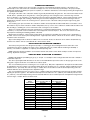
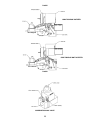
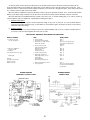
P250AF DIRECT SPARK ELECTRODE LOCATION
1/4”
(6.35 mm)
7/16”
(11.11 mm)
1/16”
+/- (1.587
mm)
1/16”
+/- (1.587
mm)
1/8” (3.175 mm) GAP
31/64”
(12.3 mm)
1/16”
+/- (1.587
mm)
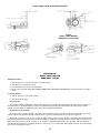
P265DI
DIRECT SPARK IGNITION
HONEYWELL S87K SYSTEM
P250AF/P265-DI
DIRECT SPARK IGNITION
HONEYWELL SYSTEM
Starting the burner:
1)
2)
3)
4)
Turn the gas valve control knob to “OFF”, wait five minutes.
Turn gas valve control knob to “ON”.
Set room thermostat above room temperature.
If burner does not light, SHUT OFF BURNER COMPLETELY AND WAIT FIVE MINUTES, then repeat steps 1 through 3
above.
To shut off burner:
1) Turn the gas valve control knob to “OFF”.
2) Turn off electrical supply.
DESCRIPTION
The Honeywell S87K (24VAC) Direct Spark Ignition Systems operate through a thermostat to provide a means of ignition for
the main burner on gas-fired equipment. This is accomplished by generating a spark between high voltage electrode and
ground. Once the flame is established a flame rod monitors the main burner flame.
SEQUENCE OF OPERATION
On a call for heat, voltage is applied to the ignitor across Terminals 1 (power) and 6 (ground) of the input connector. A high
voltage spark is then generated from the spark electrode to ground. Simultaneously, the gas valve is energized.
At the start of each heat cycle, there is a “Trial for ignition period” of three seconds duration. Normally main burner flame will
be established before the end of this period. Once the flame is established, sparking will cease and the “flame rod” will provide
flame monitoring for the remainder of heat cycle. If the flame is extinguished during this cycle, the ignitor will start sparking
automatically in an attempt to re-establish the flame. If this does not occur within the “Trial for ignition period,” the system will go
into lockout, closing the gas valve.
16