1
IOMIFJ-1
INSTALLATION, OPERATION AND MAINTENANCE
MANUAL FOR IFJ INDIRECT GAS-FIRED HEATERS
ATTENTION: READ THIS MANUAL AND ALL LABELS ATTACHED TO THE UNIT CAREFULLY BEFORE
ATTEMPTING TO INSTALL, OPERATE OR SERVICE THESE UNITS! CHECK UNIT DATA PLATE FOR
TYPE OF GAS AND ELECTRICAL SPECIFICATIONS AND MAKE CERTAIN THAT THESE AGREE WITH
THOSE AT POINT OF INSTALLATION. RECORD THE UNIT MODEL AND SERIAL No.(s) IN THE SPACE
PROVIDED. RETAIN FOR FUTURE REFERENCE.
FOR YOUR SAFETY
The use and storage of gasoline or other flammable vapors and liquids in open containers in the vicinity of this appliance is hazardous.
POUR VOTRE SÉCURITÉ
L'utilisation et l'entreposage d'essence ou d'autres liquides ou produits émettant des vapeurs
inflammables dans des récipients ouverts à proximité de cet appareil est dangereux.
FOR YOUR SAFETY
If you smell gas:
1. Open Windows
2. Don’t touch electrical switches.
3. Extinguish any open flame.
4. Immediately call your gas supplier.
c
POUR VOTRE SÉCURITÉ
Si vous sentez une odeur de gaz :
1. Ouvrez les fenêtres.
2. Ne pas actionner d'interrupteur.
3. Éteindre toute flamme ouverte.
4. Appelez immédiatement votre
fournisseur de gaz.
WARNING: Improper installation, adjustment, alteration, service or maintenance can
cause property damage, injury or death. Read the installation, operating and maintenance
instructions thoroughly before installing or servicing this equipment.
AVERTISSEMENT : Une installation déficiente, de même qu'un mauvais réglage,
modification, entretien ou maintenance peuvent occasionner des dommages matériels, corporels voire causer la mort. Lire attentivement les instructions d'installation,
d'utilisation et d'entretien avant d'installer ou d'intervenir sur cet appareil.
WARNING
Install, operate and maintain unit in accordance with manufacturer's instructions to avoid
exposure to fuel substances or substances from incomplete combustion which can cause
death or serious illness. The state of California has determined that these substances
may cause cancer, birth defects, or other reproductive harm.
INSTALLER'S RESPONSIBILITY
Installer Please Note: This equipment has been test fired and inspected. It has been shipped
free from defects from our factory. However, during shipment and installation, problems such as
loose wires, leaks or loose fasteners may occur. It is the installer's responsibility to inspect
and correct any problems that may be found.
4830 Transport Drive, Dallas, TX 75247 Phone: 214-638-6010 Fax: 214-905-0806
www.appliedair.com
SECTION I - FOREWORD
As is the case with any fine piece of equipment, care
must be taken to provide the proper attention to the operation and maintenance detail of this machine.
This manual of instructions along with the burner and
draft regulator IOM's has been prepared in order for
you to become well-acquainted with those details, and
in doing so, you will be able to give your Indirect GasFired System the care and attention which any piece of
equipment needs and deserves.
It is the customer and installation personnel
responsibilty to determine if the unit is equipped
with all of the safety devices required for the particular application. Safety considerations include
the accessibility of the unit to non-service personnel, the provision of electrical lockout switches,
maintenance procedures and automatic control
sequences. Clearly mark any shutoff devices.
Table of Contents
Section I: Foreword and Table of Contents ................. 2
Section II: General Information ................................... 3
Section III: Installation ................................................. 4
Section IV: Pre-Start Up ........................................... 12
Section V: Unit Start Up ............................................ 15
Section VI: Unit Shut Down ....................................... 18
Section VII: Troubleshooting ..................................... 19
Section VIII: Servicing the Burner ............................. 44
Section IX: Maintenance Schedule and
Lubrication Requirements ...................... 48
Section X: Replacement Parts .................................. 53
* IMPORTANT NOTICE *
Applied Air assumes no responsibility for loss or damage in transit; therefore, you should protect yourself
by following these instructions. Failure to do so is your
responsibility.
BILL OF LADING
Save your bill of lading. It is a contract, and you will need
it, provided you have to file a loss or damage claim. Remember, claims are outlawed after nine months.
LOSS IN TRANSIT
Before you sign for this shipment, check against the bill
of lading, also the transportation company's delivery
ticket. Make sure that you get the exact total of articles
listed. Should the delivery ticket show more or less
items than you are offered, then the carrier's agent must
mark the difference on your freight bill before you sign.
VISIBLE DAMAGE IN TRANSIT
If something is damaged, accept the shipment only
if the carrier's agent places a notation on your freight
bill explaining the nature and extent of damage. Upon
inspection of article, make claim to the delivering carrier.
CONCEALED DAMAGE IN TRANSIT
Sometimes transit damage is not noticed until the goods
are unpacked. In such cases, notification to the carrier
must be made within fifteen (15) days of receipt of shipment. In such cases, save the packages and packing
material, then notify the transportation company at once,
and request an inspection. When the inspector calls,
have him make out and leave a "concealed" bad order
report. He is obliged to give one to you. Insist on it.
DISPOSITION OF DAMAGED ARTICLES
Never return damaged articles to us. They are the property of the transportation company when the claim is
filled. They will give you disposition instructions.
PACKING
We comply with the packing requirements of the transportation companies, and your bill of lading proved that
everything was in good condition when shipped. That
bill of lading contract requires them to deliver in perfect
condition.
–2–
SECTION II - GENERAL INFORMATION
A. Purpose
The purpose of this manual is to present a guide for
proper installation, maintenance, and operation of the
Indirect Gas-Fired System, and supplement, but not to
replace, the services of qualified field service personnel
to supervise the initial start-up and adjustment of the
unit. Persons without previous experience with large
commercial and industrial heating equipment should not
attempt the initial adjustment and checkout procedure,
which is essential before such installations may be
considered ready for operation. This manual should be
made readily available to all operating personnel as an
aid in troubleshooting and proper maintenance. Due
to the custom nature of Applied Air equipment, not all
possibilities are addressed in this manual. The customer
or installer can obtain information from Applied Air’s
sales representative or the Applied Air factory.
Shipments are made F.O.B. Dallas, Texas by truck. The
unit is securely strapped, tied, and blocked to prevent
shipping damage. All shipments are checked by an
inspector before they are accepted by the carrier. Parts
that are shipped un-mounted are noted on the bill of
lading. These parts, where feasible, are packaged and
shipped with the units. Upon receipt of shipment, all
units should be checked against the bill of lading to
insure all items have been received. All equipment (and
any optional accessories) should be checked carefully
for physical damage in the presence of the carrier’s
representative. If parts are missing or damage has
occurred, a claim should be filed immediately with the
carrier.
WARNING: Failure to comply with general safety
information may result in extensive property
damage, severe personal injury or death.
All Indirect Gas–Fired units are given a complete
operations test and control circuit checkout before
shipment. Copies of the wiring diagram, piping diagram
and bill of material are included with each unit shipped.
If correspondence with the factory is necessary, please
provide the unit model and serial number.
B. Shipping
Base Indirect Gas-Fired units are shipped completely
assembled where shipping limitations allow. Optional
inlet hoods, filter and /or damper sections, or other
large accessories are assembled and shipped mounted
and wired whenever possible within limitations of
shipping and handling. Some optional accessories
shipped separately may require field assembly. Any
wired accessories, which have been disassembled for
separate shipment, require no additional conduit or wire
for field reassembly. All wire leads will be tagged for
ease of reconnection in the field.
C. Optional Factory Service
Periodic service on any piece of mechanical equipment
is necessary for efficient operation. A nationwide
service support network is available to provide quick
and dependable servicing of make-up air, heating,
ventilating, or air handling types of equipment. The
factory also offers start-up service, which includes the
presence of a service engineer to supervise the initial
start-up and adjustment of the equipment and provide
instructions for the owner’s maintenance personnel in
proper operations and maintenance. Consult factory for
quotations on periodic or start-up service.
If the heater and/or accessories cannot be installed
immediately, they should be stored in a clean
dry environment. If this is not possible and the
heater must be stored outdoors, it should be
protected from the weather with tarpaulins or
plastic coverings. Rotate the fans monthly. Prior
to beginning installation of a unit that has been
in storage for weeks or months, the unit and its
components should be closely inspected.
–3–
SECTION III - INSTALLATION
FOR CANADIAN INSTALLATIONS ONLY
1. All installations must conform with local building codes,
or in the absence of local codes, with current CAN/CGAB149-Installation Codes for Gas Burning Appliances and
Equipment.
2. All electrical connections must be in accordance with
Canadian Electrical Code, Part 1, CSA Standard C22.1.
During transit, unloading and setting of the unit; bolts
and nuts may have become loosened, particularly in the
pillow block ball bearing assemblies in the fan section. It is
recommended that all nuts and set screws be tightened.
Turn fan shaft by hand to make certain that blower does
not rub against blower housing, and that bearing set
screws are tight.
All electrical connections must conform to the current
edition of ANSI/NFPA No. 70 National Electrical Code
and applicable local codes: in Canada, to the Canadian
Electrical Code, Part 1 CSA Standard C22.1. The
following recommendations are not intended to supplant
any requirement of federal, state, or local codes having
jurisdiction. Authorities having jurisdiction should be
consulted before installations are made. Local codes
may require additional safety controls and /or interlocks.
All installations in airplane hangers must be in
accordance with current ANSI/NFPA No. 409. All
installations in public garages must be in accordance
with current NFPA No. 88A and NFPA No. 88B.
If units are not set immediately, cover all openings that
might be exposed to the weather.
CAUTION: Do not install heating system in corrosive
or flammable atmospheres! Premature failure of, or
severe damage to the unit will result!
CAUTION: Heating system must not be installed in
locations where air for combustion would contain
chlorinated, halogenated or acidic vapors. If
located in such an environment, premature failure
of the unit will occur!
A. Handling the Equipment
As explained previously, the basic unit is designed for
shipping in one piece where shipping limitations allow.
Some optional accessories may require field mounting.
Rotate fans monthly.
IMPORTANT: Lift and install the modules or sections
of a unit separately. Flange connections provided
between modules or sections are not structural
and damage will occur if any attempt is made to lift
modules that have flanged together.
See the specification sheet and submittal drawing
for unit or section weight and to determine proper
orientation for each section.
When unloading sections and/or units or moving
equipment to its final location, exercise care to avoid
distortion. Lift sections and/or units only by the
lifting lugs provided.
WARNING
BASE SECTION MAY TIP OVER
The base section, with the control panel, is top
heavy to the front side. Use extreme caution
when moving this section from the sides or rear
with a fork lift or similar machine.
RIGGING AND MOUNTING – IFJ UNITS
The IFJ unit has been designed for rigging and handling
through the use of special lifting lugs installed on the top
and/or sides of each unit. When unloading and setting the
unit, use the lifting lugs provided or move the equipment
on rollers. Hooks, jacks, or chains must not be used
around the casing, main control panel or exterior mounted
controls.
–4–
Warning: To insure that a proper unit lift is
made, lift unit approximately 24 inches and
verify proper center of gravity lift point. To avoid
dropping of unit, reposition lifting point if unit
is not level. Failure to properly lift unit could
result in death or serious injury or possible
equipment or property-only damage.
–5–
B. Locating the Unit
Prior to locating the unit, authorities having jurisdiction
should be consulted before installations are made. Approval
permits should be checked against the unit received.
In addition to the combustible clearances listed above,
access for service should be allowed around the unit.
The recommended minimum access clearance is
shown in Table 2.
The unit should be installed on a non-combustible pad or
concrete flooring with adequate clearances for service,
air intake and air discharge. The unit should be located
with the rear of the cabinet as close to the wall as the
applicable codes will allow. In the absence of any code,
position as near to the wall as the flue pipe, draft regulator,
and field supplied draft inducer (if applicable) will allow.
Table 2
Unit
Size
Combustion air shall be provided at a rate of at least 10
CFM, or 1 square inch of free opening, per 1000 BTU
per hour of rated input. If a separate mechanical means
provides this air, an interlock with the combustion
blower shall be provided.
*Optimum clearance for shaft removal would be
equivalent to cabinet width.
The rated output of gas burning appliances decreases
with higher altitudes above 2,000 feet, the furnace shall
be de-rated 4 % for each additional 1,000 feet of altitude
above sea level. Factory testing rating plate information
is recorded on sea level conditions. High altitude ratings
may be obtained by a change in manifold pressure.
Appliances must be suitably marked to indicate their
altitude adjusted input rating.
If the unit is located within ten (10) feet of a wall, place
the solid (blank) side of the discharge facing the wall.
Under no circumstances should this equipment be
installed in a negatively pressurized space. Consult
jurisdictional authority for proper ventilation requirements.
Combustion air containing or recirculation of room air may
be hazardous in the presence of:
a) Flammable solids, liquids and gases.
b) Explosive materials (i.e., grain, dust, coal dust.
gunpowder, etc).
c) Substances, which may become toxic when, exposed
to heat (i.e., refrigerant, aerosols, etc.).
Locate the unit exactly level. Special attention should
be given to the electrical, and fuel connection points.
The minimum clearance to combustible material must
be maintained as listed in Table 1
All
Sizes
Front and Sides
48 inches
Make a visual inspection to insure no damage has
occured to the unit during installation.
Place the base section (with blower or fan) in the
desired location. Attach the bottom flange of the unit to
floor using anchors, lag bolts or screws. Gasket the top
flange and carefully position coil box, extension plenum,
or discharge section on top of base section and attach
with nuts and bolts and caulk the seams. Continue
adding other sections on top as required.
WARNING
BASE SECTION MAY TIP OVER
The base section, with the control box, is top
heavy to the front side. This section MUST be
securely fastened to the non-combustible pad
or concrete flooring BEFORE attempting to
assemble the other section(s) to it.
IMPORTANT – Barriers should be provided to
protect the unit and the integrity of utility piping
to the unit from any collision with forklifts or
other hazards within the selected location. Do not
obstruct combustion air openings or ventilation
grilles.
Table 1
Minimum clearance to combustible material, also,
consult local codes and regulations.
Front*
Rear
Right
Left
Top
Floor
Minimum
Access*
Clearances to Combustible Material
Vertical Units
48 inches
18 inches
18 inches
18 inches
18 inches
Zero
*Consider control side as front of unit
–6–
C. Location of Accessories
Where applicable, standard or optional accessories will
be placed inside the fan section of the unit for shipment,
and must be removed and installed by the mechanical or
electrical contractor.
Remotely located discharge or inlet dampers must be
equipped with an end switch and interlocked to insure
maximum design opening before starting and running
circuits may be energized.
Field constructed intake accessories should be properly
designed to minimize the entry of rain and snow.
Each unit comes with a Draft Regulator and a field
supplied Draft Inducer may also be supplied. It is very
important that you follow the installation instructions
provided with these parts regarding location,
mounting and adjustments. These instruction sheets
should be available for the start-up technician.
D. Electrical Connections
Warning: Open all disconnect switches and
secure in that position before wiring unit.
Failure to do so may result in personal injury or
death from electrical shock.
If optional disconnect is not furnished with heater, the
field provided disconnect must be of the proper size
and voltage. Refer to unit nameplate for minimum
circuit ampacity and voltage. The disconnect must be
installed in accordance with Article 430 of the current
edition of ANSI/NFPA No. 70 National Electrical Code,
and applicable local codes; in Canada, to the Canadian
Electrical Code, Part 1, CSA Standard C22.1.
Check the supply voltage before energizing the unit. The
maximum voltage variation should not exceed ±10%.
Phase voltage unbalance must not exceed 2%.
NOTE: Should any original wire supplied with the
heater have to be replaced, it must be replaced with
wiring material having a temperature rating of at
least 105°C.
E. Venting
All venting installations must conform to Part 7, Venting
of Equipment in the current version of the National Fuel
Gas Code ANSI Z223.1, or applicable provisions of local
building codes. The National Fuel Gas Code is subject to
change, questions regarding venting requirements should
be directed to the local authority having jurisdiction.
All Indirect Fired Units are Category III appliances
and must be vented. Each unit must have an individual
vent pipe and vent terminal.
Warning: Controls must be protected from water. Do not allow water to drip on the electrical
controls.
Note: Before installing any wiring, check the unit
rating plate for power supply voltage, and minimum
amperage.
All electrical connections must conform to the current
edition of: ANSI/NFPA No. 70 National Electrical Code
and applicable state and local codes; in Canada, to the
Canadian Electrical Code, Part 1 CSA Standard C22.1
and applicable provincial and local codes. Since shipment
of unit may require disassembly after factory check and
test, reconnection of some electrical devices will be
required in the field. Connect electrical wires (supplied
in factory furnished conduit) to appropriate terminals.
All leads are tagged to facilitate field connections. See
wiring diagram provided with equipment. Complete all
wiring to any optional accessories as shown on unit bill of
material and electrical wiring diagram as required before
applying voltage to the unit.
If damper actuators require field wiring, be sure the gasket
and cover are securely mounted and assembly is watertight.
Recommended vent pipe is 14 Gauge Series Stainless
Steel. DO NOT support the weight of the stack draft
regulator or field supplied draft inducer on the unit.
Insulate single wall vent pipe exposed to cold air or
running through unheated areas. Use as few elbows as
possible and tape flue pipe joints with fireproof paper or
other approved material.
The venting system for these heaters shall terminate at
least four feet below, four feet horizontally from, or one
foot above any door, window, or gravity air inlet into any
building. All vents must be able to maintain the negative
draft shown on rating plate in high fire.
The vent pipe diameter must be a minimum of 8" in
diameter.
The vent pipe should be fitted with a drip leg with a clean
out and a drain plug in the bottom. The vent pipe shall be
constructed so that any water that collects in the stack
will remain in the stack drip leg and not drain into the heat
exchanger. Be sure drip leg is made so water will not fall
on heater controls when drain plug is removed.
Entry location for all field-installed and control wiring is
through the control panel.
–7–
Pitch horizontal pipes downward ¼ inch per foot toward
outlet for condensate drainage. Support horizontal runs
as required to prevent sagging.
Refer to the heater’s rating plate to determine the
minimum gas supply pressure for obtaining the
maximum gas capacity for which this heater is specified.
Vents should terminate that would not cause a down
draft to occur. This could affect the negative pressure
required in the heat exchanger. Do not install dampers
or other restrictive devices in the flue vent pipe. The
draft regulator or field supplied draft inducer are the only
approved devices to be used on this heater.
Refer to the heater’s rating plate to determine the
maximum supply pressure to the heater.
The stack should not be installed in such a manner that
access to the components is obstructed. Guy wires may
be required to brace the stack above rooflines.
WARNING: CARBON MONOXIDE! Your venting
system must not be blocked by any snow, snow
drifts, or any foreign matter. Inspect your venting
system to ensure adequate ventilation exists at
all times! Failure to heed these warnings could
result in carbon monoxide poisoning (symptoms
include grogginess, lethargy, inappropriate
tiredness, or flu-like symptoms).
The appliance and the additional shutoff valve must
be disconnected from the gas supply piping system
during any pressure testing of that system at test
pressures in excess of ½ PSIG.
The appliance must be isolated from the gas supply
piping system by closing it’s individual manual
shutoff gas valve during any pressure testing of the
gas supply piping system at test pressure equal to
or less than ½ PSIG.
Correctly sized piping must be run to the unit.
F. Field Piping
Gas Piping
All gas piping must be in accordance with the
requirements outlined in the National Fuel Gas Code
– ANSI Z223.1. It is required that a ground union be
installed adjacent to the manifold for easy servicing. A
drip leg and/or filter should be provided upstream of the
unit’s inlet gas connection. An additional shut-off must be
located external of the unit’s enclosure where required by
local code. The location of this valve must comply with all
local codes. A 1/8 inch N.P.T. plugged tapping, accessible
for test gauge connection, must be installed immediately
upstream of the gas supply connection to the unit.
WARNING:To avoid equipment damage or possible
personal injury, do not connect gas piping to this
unit until a supply line pressure/leak test has been
completed. Connecting the unit before completing
the pressure/leak test may damage the unit gas
valve and result in a fire hazard.
DANGER: Never use an open flame to detect
gas leaks. Explosive conditions may exist which
would result in personal injury or death.
The gas line should be supported so that no strain is
placed on the unit and does not rub on any surface. Pipe
compounds, which are not soluble to liquid petroleum
gases, should be used on threaded joints.
CAUTION: The burner itself has been shipped
attached to the front of the heater and combustion
chamber. After shipping, it is possible the burner is
no longer positioned properly as far as proximity
to the chamber. This must be checked against the
dimensional drawing for correct burner insertion
into the chamber and set if necessary.
Please note that gas line pressure must be as
shown on specification plate when unit is operating
at full input. The high-pressure regulator and relief
valve should be, if possible, mounted at least 5 to
10 feet upstream from the gas valve on the unit (if
applicable).
Refrigerant Piping
Refer to drawing on following pages. Check to ensure
refrigerant lines do not rub against the cabinet or other
refrigerant lines.
G. Field Wiring and Remote Control Installation
1. If the optional low temperature was not an integral
part of the heater, the factory recommends that a low
temperature limit control be installed in areas where freeze
protection is needed in the event of burner shut down.
2. Connect the power lines to the line side of the power
distribution block or optional main disconnect switch.
3. Field wiring is indicated on the wiring diagram,
typically dashed lines. Where field wiring of the control
circuit is required, take care to size the wires for a
maximum 10% voltage drop. The VA rating of the
transformer should be the maximum load.
4. Mount and wire remote control panel, thermostat
temperature sensors, and any other field-installed
controls as indicated on the unit control-wiring diagram.
5. Connect all wiring to the appropriate field wiring
terminal and any shielded or twisted wires as indicated
on the unit control-wiring diagram.
6. Field wiring shall have a temperature rating of at
least 105°C. The minimum size of the supply cable
circuit shall be sufficient for the maximum ampacity of
the heater.
–8–
–9–
– 10 –
H. Locating Temperature Controls
The room or outdoor thermostats should be mounted where
they will not be subjected to direct impact of the heated air
or radiant heat from the sun. It is also recommended that
thermostats, especially those with mercury bulb contacts,
be mounted on a vibration free surface. The sides of
building columns away from the heater or interior walls are
usually the location best suited for mounting thermostats.
I. Drains and Traps
Evaporator Coil – Blow Through
The cooling coil section can be located in the unit so
that supply air is blown through the evaporative coil(s).
A properly piped trap should be installed to control
the condensate flow from the unit and also eliminate
conditioned air from being blown out the condensate
drain.
On initial start-up, it may be necessary to fill the trap
manually or, after unit has operated sufficiently for a
small amount of condensate to collect in the drain pan,
turn off the unit and the trap will automatically fill.
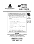
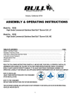
SUGGESTED P-TRAP DESIGN FOR CONDENSATE
DRAIN PANS UNDER A POSITIVE PRESSURE
90° LONG RADIUS
PVC ELBOW
NIPPLE
90° LONG RADIUS
PVC ELBOW
J
TO
DRAIN
DRAIN PAN
PVC ADAPTER FITTING
FPT x SLIP
PVC PIPE
NIPPLE
PVC PIPE
NIPPLE
G
NOTE:
'G' TO BE A MINIMUM OF
1/2" PLUS THE TOTAL SYSTEM
STATIC PRESSURE ("W.C.).
'J' TO EXCEED THE POSITIVE
STATIC PRESSURE IN "W.C. OF
THE SECTION OF THE UNIT
WHERE THE DRAIN IS INSTALLED.
PVC RETURN BEND
(10/30/09 C000659B)
DRAIN PLUG
10/30/09 C000659B
– 11 –
SECTION IV – PRE START-UP
Do not attempt start-up without completely reading
and understanding this manual.
Pre Start-Up
The owners representative or equipment operator should
be present during start-up to receive instructions on care
and adjustments of the equipment.
All equipment has been factory tested, adjusted, metered
and inspected to meet conditions set at the time the order
was placed. Only minimal adjustments should be required.
All information in this service manual is typical. All products
are semi-custom and changes may occur.
CAUTION: Line side of disconnect may be energized.
Follow proper “lockout/tagout” procedures.
NOTE: A qualified service engineer should perform all
servicing and adjustments of the Indirect Gas-Fired
unit.
Perform a visual inspection, internally and externally, to
make sure no damage has occurred and that everything
is secure. This inspection is very important and should be
completed with great care given to detail. A good pre-start
inspection will insure against possible unit damage on
start-up and will save valuable analysis time.
1. Check that the physical condition of the unit exterior is
acceptable.
2. Check that any insulation inside the unit is properly
secured.
3. Check all terminals for loose connections and inspect
all wiring terminations to insure that all crimped
connections are tight.
4. Inspect the fan and motor bearings and lubricate if
necessary.
CAUTION: DO NOT RUPTURE GREASE SEALS.
5. Inspect pulleys and belts for tightness, tension and
alignment. Do not overtighten belts.
6. Check set screws on all bearings, pulleys, fans and
couplings for tightness.
7. Check voltage supplied to disconnect switch; the
maximum voltage variation should not exceed + 10%.
Phase voltage unbalance must not exceed 2%.
8. Check thermostat(s) for normal operation.
9. Check that fans turn freely in housing.
10. Check that the area around the unit is clear of
flammable vapors or containers of flammable liquids.
11. Visually inspect all fuel lines for damage and/or
contact with a surface that can cause damage over
time from rubbing. Check that all piping connections,
particularly unions, are tight. Check all gas piping for
leaks using a soap bubble solution. The most common
types of problems found relative to the gas train itself
is to make sure it is free of foreign material within the
gas piping. This will interfere with the proper operation
of the gas train components and burner. Purge all air
from gas lines per gas codes.
12. Check that inlet gas pressure is the same as shown
on the rating plate.
13. Check that all accessories requiring field wiring have
been properly installed.
14. Check burner for proper location and alignment.
15. Check that filters, filter stops, accessories and any
ship loose items are installed properly.
16. Check that vent lines (if applicable) are run to
atmosphere on gas regulators and pressure switches
for indoor units. Vent lines should terminate outside
the building, with a turndown elbow and bug screen.
Note that some units will use vent limiters and vent
lines are not required. If vent lines are even partially
plugged, this will interfere with proper venting of
pressure control devices.
17. Check that all manual gas shut-off valves are closed.
18. When failure or malfunction of this heater creates a
hazard to other fuel burning equipment, (e.g. when
the heater provides make-up air to a boiler room), the
heater is to be interlocked to open inlet air dampers or
other such devices.
19. Motor overload relay setting should match the motor’s
nameplate full load amperage.
20. Check any dampers or mixing boxes (if supplied).
Make sure all damper linkage is free to move and no
binding will occur. If dampers are of the modulating
type, check control capillary tubes to insure that the
tubes and bulbs are in the proper location and will not
rub against any other parts.
21. Check to ensure all manual reset safety devices
have been reset and limits are in the normal
operating position.
22. Check to make sure the draft regulator and field
supplied draft inducer (if applicable) and airflow
switch is wired and installed in the proper location.
See the installation instructions accompanying these
accessories.
23. Check that all fuses are installed.
24. Check to ensure the flue stack is installed properly
and is free of obstructions.
– 12 –
SUGGESTED TOOLS AND INSTRUMENTS
U-Tube Manometer (0 – 10" W.C.)
Flue Gas Test Equipment
Standard Hand Tools
D.C. Volt Meter/Microammeter
Draft Gauge
Volt/Ohm meter
Tachometer
Stack & Temperature Thermometer
Gas Pressure Gauge (0 – 35 lbs.)
Ammeter/Amprobe (or equal)
SUGGESTED CONTROLS SETTINGS
FL-02 High Limit..............................................…200o F
PS-04 Low Gas Pressure Switch...............…..1.0” W.C.
PS-07 High Gas Pressure Switch..….........125% above
burner firing rate
PS-10 Main Air Proving Switch Adjust to field condition
PS-12 Clogged Filter Switch.….Adjust to field condition
TC-01 Room Thermostat ……… Customer Discretion
BEFORE ATTEMPTING TO START THE HEATER, READ THE TYPICAL
SEQUENCE OF OPERATION AS SHOWN BELOW:
Typical Sequence Of Operations Note: This sequence
is written for only the burner safety and operating
portion of the heater. The following sequence assumes
all safety interlocks are closed and optional unit main
disconnect switch (SW-01) is closed. Other control
systems for dampers, mixing boxes, and temperature
controls are included in the unit typical sequence of
operation and/or wiring diagram:
1. With main supply air fan(s) on, thermostat calling for
heat, and all switches and operating controls in their
normal position, the field supplied Draft Inducer (if
applicable) will be energized. At this time, voltage
(24VAC) is applied to motor start relay and air
switch. Once the fan motor reaches operating rpm,
combustion air pressure is sensed by the air proving
switch and closes the switch contacts energizing the
S89F gas primary control.
2. The S89F gas primary control has an internal 30
second prepurge timer. After the initial 30 second
prepurge, an internal 8 second safe start check of
the 89F will commence. Once this is successfully
completed, the S89F simultaneously energizes the
gas valve and ignition transformer. Gas flows and
the transformer produces an approximate 7300
volt spark end point grounded at the burner head
establishing main burner flame.
3. At the start of each heat cycle, there is a trial for
ignition period of four (4) seconds duration. Normally,
burner flame will be established before the end of this
period. Once the flame is established, sparking will
cease and the flame rod will provide flame monitoring
to the S89F gas control primary for the remainder of
the heat cycle. If the flame should be extinguished
during the heat cycle, the S89F gas control primary
will go into the 30 second prepurge and a 8 second
safe start check, then re-energize the gas valve and
ignition transformer in an attempt to establish the
main burn flame. If this does not occur within the 4
second trail for ignition period, the S89Fgas primary
control will go into lockout, de-energizing the gas
valve and ignition transformer.
4. To restart the system, the main power or thermostat
must be de-energized momentarily, then reenergized. If at any time during the heat cycle, there
is an insufficient supply of combustion air to the
burner, the air switch will open, putting the system
into lockout closing the gas valve.
– 13 –
ROOM THERMOSTAT (TC-01) SEQUENCE:
KEYS ARE USED TO:
• set current time and day
• program times and setpoints for heating and cooling
• override the program temperatures
• display present setting
• set system and fan operation
• perform simple configuration
SYSTEM SETTINGS:
In the AUTO mode:
Thermostat automatically changes between heating
and cooling based on indoor temperature.
In the COOL mode:
Thermostat controls two stages of cooling by energizing
the optional cooling relays (RE-77 and RE-78). The
cooling relays provide dry contacts for operating remote
equipment.
FAN SETTINGS:
In the ON mode:
The fan will run continuously in the occupied mode
and will cycle with a call for cooling or heating in the
unoccupied mode. The thermostat energizes the fan
enable relay (RE-15) which will then enable the fan
starter (ST-01).
LOSS OF POWER:
The room thermostat (TC-01) maintains programmed
times and temperatures for the life of the product. Clock
and day information is retained for a minimum of 48
hours.
NOTE: To achieve the 48-hour power-loss clock
retention, the T7350 must be powered for at least
five (5) minutes.
SERVICE SWITCH:
The service switch (SW-24) will de-energize the control
circuit disabling the unit from running. Caution: the
service switch does not disconnect all power.
NIGHT SET BACK:
The night set back function is integral to the room
thermostat (TC-01).
TIME CLOCK:
The time clock function is integral to the room thermostat
(TC-01) which has 365 day programming with up to two
occupied and two unoccupied periods per day.
For a more detailed setup procedure, see the
Troubleshooting Guide section for the T7350.
In the AUTO mode:
Fan always cycles with call for heat or cool. The
thermostat energizes the fan enable relay (RE-15)
which will then enable the fan starter (ST-01).
DEFAULT SETPOINTS:
Heating Occupied 70°F (21°C), Heating Unoccupied
55°F (13°C).
Cooling Occupied 75°F (24°C), Cooling Unoccupied
85°F (29°C).
– 14 –
SECTION V – UNIT START-UP
Before attempting to start the heater, you must read
and understand this manual as well as the burner IOM,
sequence of operation, electrical schematic, ignition
control module and gas component instructions. You
must also be familiar with the adjustment of the draft
regulator and field supplied draft inducer (if applicable).
WARNING: During installation, testing, servicing
and trouble shooting of this product, it
may necessary to work with live electrical
components. Have a qualified licensed
electrician or other individual who has been
properly trained in handling live electrical
components to perform these tasks. Failure to
follow all electrical safety precautions when
exposed to live electrical components could
result in death or serious injury.
Turn Fan “on-off” switch to “on” position. Check for
proper fan RPM. Check that all amp draws do not
exceed nameplate ratings and overloads are set to
nameplate amps.
Check to make sure all dampers and controls are
working properly.
Turn Fan “on-off” switch to “off” position.
NOTE: When setting up the burner for the first
time or if the appliance has been shut down for
an extended period of time, these same start up
procedures should be followed.
Open pilot and first main gas shut-off valves slowly.
Check the gas supply pressure by replacing the
plug fitting on the inlet pressure tap of the gas
valve with a pressure gauge with appropriate range.
Check that pressure reading is within the specified
range on the raring plate.
CAUTION: Danger of sharp metallic edges that
can cause injury. Take care when servicing unit
to avoid accidental contact with sharp edges.
Make sure all manual gas valves are closed.
Make sure all doors and service panels have been
closed or replaced.
Turn main disconnect switch off. Check the incoming line
voltage to match unit nameplate rating. If voltage is over
+10% of nameplate rating or phase voltage unbalance is
over 2%, notify contractor or power company.
NOTE: To adjust gas pressure on supply lines where
a regulator has been installed (to set inlet pressure
to rating plate maximum pressure), remove dust
cap of main gas regulator and turn adjusting screw
clockwise to increase pressure or counterclockwise
to decrease pressure.
Check main gas line for leaks using a soap solution.
Setting the Main Flame
If power supply meets requirements turn main
disconnect switch on. Turn Fan “on-off” switch to
“on” position. Inlet shut-off damper(s) (if applicable)
opens, after end switch has proven damper is open
the blowers or props run.
Turn Fan “on-off” switch to “off” position. Check
supply fans for proper rotation. The burner and
draft inducer (if applicable) rotation can be checked
when the heat section is started.
CAUTION: Do not attempt to start the heater when
furnace is full of vapor or combustion chamber is
very hot.
CAUTION: At no time should you stand in front of
the relief door.
NOTE: To change rotation of the fans, simply
interchange any two (2) of the line leads of the
motor starter for 3 phase motors. On single-phase
motors, refer to motor nameplate.
– 15 –
Connect manometer to the outlet pressure tap of the unit
gas valve.
Depress the combination gas valve manual control now
and turn to “ON” position.
Connect a DC microammeter between the SENSE
terminal and the flame rod sensing wire.
Set the thermostat or operating control to call for heat.
The burner will start and go through the applicable
sequence of burner/primary gas control operation.
Depress the combination gas valve manual control knob
and turn to “OFF” position.
Adjust the primary air to No. 4 and off-cycle damper to
No.1-1/2.
Turn Fan and Heat-Off-On switches to the ON
position and check rotation of burner fan and field
supplied draft inducer (if applicable).
NOTE: 3 or 4 trials may be needed to purge air from
gas line.
CAUTION: If main flame does not light within a few
seconds. Shut the burner down and repeat steps.
You may have to eliminate air from the main gas line.
The main gas pressure and/or burner air setting may
also need to be readjusted.
If limits and all safety controls are closed, the burner
and field supplied draft inducer (if applicable) will run for
approximately 30 seconds before ignition trial as a prepurge cycle.
WARNING: If any flame is observed when the
burner is on standby, or if the ignition spark or
valve operator is heard to come on before the
burner reaches operating speed; immediately
turn off the gas control and main power. A
dangerous condition has developed and MUST
be corrected.
Allow the burner to run a MINIMUM of five (5) minutes
to purge combustion chamber and appliance heat
exchanger.
After the burner lights; adjust the orifice manifold pressure
regulator (if necessary) using a manometer to match
normal manifold pressure shown on unit nameplate.
Set the thermostat or operating control below room
temperature, shutting the burner and field supplied draft
inducer (if applicable) “OFF” for one ( 1) minute to RESET
the primary control.
Make sure the combustion air and gas pressure is
sufficient to provide instant ignition, a stable flame, and
flame signal.
Set all thermostats to call for heat. Set inlet ductstat (if
applicable) above outside air temperature.
After the desired input has been obtained, readjust the
primary air damper open or closed to visually obtain a
blue flame with well defined orange or yellow tips for
natural gas, or well defined yellow tips for propane gas.
Check all gas piping again for leaks using a soap bubble
solution.
See final checks and adjustments.
– 16 –
FINAL CHECKS AND ADJUSTMENTS
After the burner has been in operation for at least
ten (10) minutes, assuring combustion chamber and
heat exchanger are fully warmed; take combustion
analysis flue gas samples just ahead of the draft
control in the flue pipe.
NOTE: ALWAYS USE RELIABLE COMBUSTION TEST
INSTRUMENTS. BEING PROFICIENT IN THE USE
OF THESE INSTRUMENTS AND INTERPRETING
COLLECTED DATA IS NECESSARY FOR SAFE,
RELIABLE AND EFFICIENT BURNER OPERATION.
The following readings should be taken but not limited
to:
CO2 %
O2 %
CO %
Detectable Carbon Monoxide (CO)
•
•
•
•
Excessive Stack Temperature (480°F Above Ambient)
•
•
•
•
•
The following list covers general combustion problems
and some of the possible cures. Conditions may vary in
the field. Refer to combustion chart for efficiency.
CAUTION: Check local codes for maximum
allowable percentages and amounts of emissions.
Draft setting too high
Excess burner air
Fuel input too high
Blocked and/or restricted secondary tubes
Low Oxygen (O2)
Net Stack Temperature
Combustion Efficiency
If necessary, make adjustments on burner air shutter.
DO NOT change the fuel input rate. The draft regulator
must be adjusted by adding or removing the washer
type weights supported by the two chains. Do not move
the weight attached directly to the gate.
Fuel input too high
Not enough burner air
Restricted draft
Flame impingement
Oxygen reading must always be a positive
percentage
Make sure there is a minimum of –0.02" W.C. at relief
door when burner is in high fire with a warm stack.
Cycle burner several times to ensure smooth light off
and proper operation. Visually observe the flame pattern.
There must be no flame impingement or hot spots on the
combustion chamber that could cause scaling.
Check voltage and amperage on all motors.
Check all dampers, linkages, and locking quadrants to
make sure they are secure and operating correctly.
Check all gas piping for leaks.
Low Carbon Dioxide (CO2)
•
•
•
Fuel input too low
Excess burner air
Wrong draft setting
SAFETY AND CONTROLS CHECKOUT
Ignition Module – Close the manual gas valve before
burner. Operate unit in heat mode. The ignition module
must trip out within 5 seconds after try for ignition is
complete.
Limit Controls – The limit controls are checked by
adjusting control to a lower temperature setting while
the unit is operating on high fire and observe cut-off.
Return the adjustment to its original setting. Manual
reset may be required on some controls.
Temperature Controls – The temperature controls are
checked by adjusting control to a higher temperature
to allow burner to cycle on. Adjust control to a lower
temperature to allow burner to cycle off. Return the
adjustment to its original setting.
– 17 –
Make sure all the safeties and controls
are working properly.
SECTION VI - UNIT SHUTDOWN
A. Extended Shutdown
1. Disable the heat for 3 minutes, or a sufficient
amount of time to allow the heat exchanger to
cool down. Then disable the fans.
2. Close all the manual gas shut off valves.
3. Open the main electrical disconnect switch.
4. If the unit is to remain idle for an extended period, the fan and motor shafts should be rotated
by hand to spread the grease over the bearings.
B. Emergency Shutdown Only —
1. Open the main electrical disconnect switch.
2. Close the main manual gas valve.
– 18 –
SECTION VII - TROUBLE SHOOTING
Check Safety Shutdown Performance
WARNING: Fire or explosion hazard. Can cause
property damage, severe injury or death. Perform
the safety shutdown test any time work is done on
a gas system.
NOTE: Read steps 1 through 7 before starting, and
compare to the safety shutdown or safety lockout
tests recommended for the ignition module. Where
different, use the procedure recommended for the
module.
1. Turn off gas supply.
2. Adjust setpoint above room temperature to call for
heat.
3. Watch for ignition spark following prepurge. See
ignition module specifications.
4. Time the length of the spark operation. See the flame
safeguard relay module specifications.
5. After the module locks out, open the manual gas cock
and make sure no gas is flowing to the pilot or main
burner.
6. Reset the ignition relay (RE-02).
7. Operate system through one complete cycle to make
sure all controls operate properly.
This equipment has been electrically and fire tested prior
to shipment. However, during transit control setpoints can
change, and wiring can come loose. Do not assume controls are defective until all associated setpoints and wiring
are checked.
The following is a simplified list of possible problems and
typical causes and remedies. However, it does not cover
all possibilities, and is intended as a guide only.
Refer to the burner manufacturer IOM for additional
instructions.
WARNING: Many of the steps listed on the following pages require electrical cabinet and blower access while the unit is powered. High voltage and
moving parts are present, and these steps should
be performed by qualified service personnel. If any
of the controls requiring manual rest were at fault
this is an indication of a problem with the system
that should be investigated.
– 19 –
SECTION VII - TROUBLESHOOTING continued
Symptom
Cause
Remedy
A. Supply fan does not run.
1. Low or no voltage.
2. Fuse(s) blown.
3. Customer’s interlock not closed or
connected.
4. Room thermostat (TC-01) not
working.
5. Fan “On-Off” Switch (SW-24) in
“Off” position.
6. (RE-15) Contacts open.
7 Damper motor not operating, its
end switch not making, or
dampers binding (if applicable).
1. Check power source.
2. Replace fuse(s).
3. Close or connect customer interlock.
4. See Troubleshooting Guide for
T7350 thermostat.
5. Place switch in “On” position.
8. Overload protection on motor
starter tripped.
9. Belt(s) loose or broken (if applicable).
10. Motor may be burnt out or
incorrectly wired.
11. Bearing seized on shaft.
6. Check for power and/or replace.
7. Check for power at damper motor
and that end switch has been
wired correctly. End switch should
be wired N.O. (normally open).
Clear linkage.
8. Reset the starter by pushing red
button on starter, check amp
draw.
9. Turn power off and check belts.
10. Turn power off and check motor
and wiring.
11. Turn power off and check bearings.
B. Line voltage is not present 1. Fan “On-Off” Switch (SW-24) in
at burner.
“Off” position.
2. Room thermostat (TC-01) not
working.
3. Auxiliary switch on starter not
closed.
4. (RE-28) Contacts open.
5. High temperature limit is open.
6. High-Low gas pressure switches
open.
7. Field installed Draft Inducer motor
not running.
8. Field installed Draft Inducer air
proving switch is open.
1. Place switch in “On” position.
C. Burner motor does not run.
1. Check wiring and connection.
Correct or replace if defective.
2. Check wiring and connection.
Correct or replace if defective.
3. Check for motor clearance. Correct or replace motor if defective.
1. 24 Volts is not present on low
voltage transformer.
2. Motor start relay contacts do not
close.
3. Motor shaft does not turn freely.
– 20 –
2. See Troubleshooting Guide for
T7350 thermostat.
3. Check auxiliary circuit wiring and
contacts.
4. Check for power and/or replace.
5. Check limit for proper settings.
6. Correct gas pressure and reset
switches.
7. Check wiring, fuses, and amp draw
on motor.
8. Check for correct rotation and
switch operation. See Operating
Manual for proper installation and
adjustment.
SECTION VII - TROUBLESHOOTING continued
Symptom
Cause
Remedy
D. Ignition Control Module
goes into safety shut
down (Lockout).
1. See technical data sheets on
Ignition Control Module.
1. Determine the cause of
lockout.
E. If burner does not light
after pre-purge has timed
out and there is no
voltage at Ignition
Control Module input
terminals.
1. Low voltage transformer defective.
1. Check wiring and connection.
Correct or replace if defective.
2. Check for correct switch operation
or replace if defective.
F.
1. Ignition Control Module defective.
2. Manual gas shut-off valve closed.
3. Inlet gas pressure lower than
minimum gas pressure required.
4. No gas through high gas pressure regulator with sufficient inlet
gas pressure.
5. No gas flow through combination
gas valve.
Burner does not light after
pre-purge has timed out
and voltage is present on
Ignition Control Module
input terminals.
2. Burner air proving switch is open.
6. Type of gas supplied (natural gas
or propane) different than shown
on unit rating plate.
7. Flame detection system not sensing
flame. (See section for servicing
burner).
8. No voltage on secondary side of
ignition transformer.
9. Gas orifices obstructed or
plugged.
G. If burner lights but loses
flame during cycle and a
stable microampere
current of 0.8 cannot be
obtained.
1. Flame proving circuit grounded
by moisture.
2. Damaged insulation on flame rod
or not properly positioned in flame.
3. Poor ground path to primary
control module.
4. Ignition control locks out.
5. Poor combustion levels.
H. Burner cycles erratically.
1. Low voltages.
2. Thermostats, safeties and/or
switches opening and closing.
1. Replace Ignition Control Module.
2. Slowly open valve.
3. Increase gas pressure.
4. Clear obstruction in vent orifice or
line, replace if defective.
5. Check for proper installation, and
voltage. Correct or replace if
defective.
6. Connect to proper fuel supply or
contact factory for field conversion
parts.
7. Assure flame rod is in flame,
check wiring, and flame rod.
8. Check wiring. Replace transformer
if defective.
9. Clear obstruction or blockage.
1. Check for proper installation and/
or correct.
2. Check wiring along with flame
rod position. Correct and/or re
place if defective.
3. Check to be sure unit is properly
grounded.
4. Check wiring and connections.
Correct and/or replace if defective.
5. Perform a flue gas analysis and
correct any combustion setup
issues.
1. Check for proper voltage and
amperage on burner motor and
gas valve. Replace if defective.
2. Check operation and replace if
defective.
See burner Installation, Operation, and Maintenance Manual for additional troubleshooting
– 21 –
SECTION VII - TROUBLESHOOTING continued
Symptom
A. Insufficient cooling
Cause
Remedy
1. Cooling thermostat not working
properly.
2. (RE-77 and RE-78) contacts not
closed.
3. Evaporator coil freezing.
1. See Troubleshooting Guide for
T7350 thermostat.
2. Check for power and/or replace if
defective.
3a. Thermostat setting too low.
3b. Check filters. Clean or change as
needed.
3c. Check adjustments of TXV and
bulb location.
3d. Check airflow.
4. Check for correct superheat and
subcooling.
4. Incorrect refrigerant charge.
– 22 –
T7350 Commercial Programmable
Thermostat
FOR SINGLE- OR MULTI-STAGE CONVENTIONAL/
HEAT PUMP SYSTEMS
INSTALLATION INSTRUCTIONS
APPLICATION
Location
The T7350 Commercial Programmable Thermostat
controls 24 Vac commercial single zone heating,
ventilating and air conditioning (HVAC) equipment. The
T7350 consists of a thermostat and subbase. The
thermostat includes the display and keypad for 7-day
programming. The subbase includes equipment control
connections. The subbase mounts on the wall and the
thermostat mounts to the subbase.
MERCURY NOTICE
If this control is replacing a control that contains
mercury in a sealed tube, do not place your old
control in the trash. Dispose of properly.
Contact your local waste management authority
for instructions regarding recycling and the
proper disposal of an old control. If you have
questions, call Honeywell Customer Care Center
at 1-800-468-1502.
INSTALLATION
When Installing this Product...
1.
2.
3.
4.
Read these instructions carefully. Failure to follow
them could damage the product or cause a
hazardous condition.
Check ratings given in instructions and on the
product to ensure the product is suitable for your
application.
Installer must be a trained, experienced service
technician.
After installation is complete, check out product
operation as provided in these instructions.
CAUTION
Electrical Shock or Equipment Damage
Hazard.
Can shock individuals or short equipment
circuitry.
Disconnect power supply before installation.
Do not install the thermostat where it can be affected by:
— drafts or dead spots behind doors and in corners.
— hot or cold air from ducts.
— radiant heat from sun or appliances.
— concealed pipes and chimneys.
— unheated (uncooled) areas such as an outside wall
behind the thermostat.
IMPORTANT
To avoid electrical interference, which can
cause erratic performances, keep wiring runs as
short as possible and do not run thermostat
wires adjacent to the line voltage electrical
distribution systems. Use shielded cable. The
cable shield must be grounded only at the
controlled equipment case.
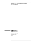
Subbase
WHEN USED TO SENSE ROOM TEMPERATURE
Install the thermostat about 5 ft. (1.5m) above the floor in
an area with good air circulation at average temperature.
(See Fig. 1.)
WHEN NOT USED TO SENSE ROOM TEMPERATURE
When using the remote-mounted temperature (and
humidity) sensor(s) to sense ambient conditions, install
the thermostat in an area that is accessible for setting
and adjusting the temperature and settings.
CAUTION
Equipment Damage Hazard.
Can damage the TIM connection beyond
repair.
Disconnect the TIM cable prior to opening or
closing the thermostat cover.
NOTE: Allow sufficient clearance below the thermostat
to plug in the TIM cable.
Install the remote-mounted sensor(s) about 5 ft. (1.5m)
above the floor in an area with good air circulation at
average temperature. (See Fig. 1.)
If multiple remote sensors are required, they must be
arranged in a temperature averaging network consisting
of four sensors. (See Fig. 2.)
Place Bar Code Here
62-0195-06
– 23 –
T7350 COMMERCIAL PROGRAMMABLE THERMOSTAT
NOTE: Only TR21 models with no setpoint adjustment
can be used for temperature averaging.
YES
NO
NO
2. Use a pencil to mark the mounting holes.
(See Fig. 3.)
3. Remove the subbase from the wall and drill two
3/16 in. (4.8 mm) holes in the wall (if drywall) as
marked. For firmer material such as plaster or
wood, drill two 7/32 in. (5.6 mm) holes.
4. Gently tap anchors (provided) into the drilled holes
until flush with the wall.
5. Position the subbase over the holes, pulling wires
through the wiring opening.
6. Loosely insert the mounting screws into the holes.
7. Tighten mounting screws.
NO
5 FEET
(1.5 METERS)
M4823A
WIRES THROUGH WALL
MOUNTING
HOLES
Fig. 1. Typical location of thermostat
or remote-mounted sensor.
SUBBASE
T4
TR21
T
TR21
T
TR21
T
T3
T
WALL
ANCHORS
(2)
T
MOUNTING
SCREWS
TR21
T
T
T
M19608
Fig. 3. Mounting the subbase.
M29184
Mounting Thermostat on Subbase
(Fig. 4)
Fig. 2. Four TR21 sensors providing temperature
averaging network for T7350 Thermostat.
With the subbase installed, mount the thermostat:
1. Engage top subbase tabs into the thermostat top.
2. Swing the thermostat down.
3. Press the lower edge of the case to latch.
Mounting Subbase
The subbase mounts horizontally.
IMPORTANT
• When using the internal temperature or humidity
sensor, the device must be mounted horizontally
(with the LCD facing upwards). Precise leveling
is not needed.
• When using remote room temperature and
humidity sensors, thermostat mounting
orientation does not matter.
Wall mounting (using standard drywall screws) is
standard. Mounting to a 2 in. by 4 in. (50.8 mm by 101.6
mm) wiring box can be accomplished:
— for a horizontal box, no extra hardware is required.
— for a vertical box, part 209651A is required.
— Mount to European standard wall box (having 2.4 in.
(60.3 mm) between mounting screws in a horizontal
line) with or without adaptive hardware.
1. Position and level the subbase.
NOTE: A level wallplate is only for appearance.
The thermostat functions properly even
when not level.
62-0195—06
NOTE: To remove the thermostat from the wall, first pull
out at the bottom of the thermostat; then remove
the top.
Wiring
Follow equipment manufacturer wiring instructions when
available. Refer to the Wiring Diagram section starting on
page 8 for typical hookups. A letter code is located near
each terminal for identification.
IMPORTANT
All wiring must comply with local electrical codes
and ordinances.
NOTE: Maximum (and recommended) wire size is 18gauge. Do not use wire smaller than 22-gauge.
1. Loosen subbase terminal screws and connect
system wires.
2. Securely tighten each terminal screw.
3. Push excess wire back into the hole in the wall.
4. Plug the hole with nonflammable insulation to
prevent drafts from affecting the thermostat.
2
– 24 –
T7350 COMMERCIAL PROGRAMMABLE THERMOSTAT
NOTE: See Fig. 5 for keypad information.
A. ENGAGE TABS AT TOP OF THERMOSTAT AND SUBBASE OR WALLPLATE.
Setting Temperature
Refer to Table 2 for the default temperature setpoints. See
the Product Data (form 63-2605) for complete instructions
on changing the setpoints.
Setting System and Fan
System default setting is Auto. Fan default setting is On.
NOTE: Use System and Fan keys to change settings.
System Settings
— Auto: Thermostat automatically changes between
heating and cooling based on indoor temperature.
— Cool: Thermostat controls cooling.
— Off: Heating, cooling, and fan are all off.
— Heat: Thermostat controls heating.
— Em Heat: Auxiliary heat serves as first stage.
Compressor stages are locked off.
B. PRESS LOWER EDGE OF CASE TO LATCH.
Fan Settings
— On: See Table 1.
— Auto: Fan always cycles with call for heat or cool.
— Conventional: The equipment (i.e. plenum switch)
controls fan operation in heat mode. Thermostat
controls fan operation in cool mode.
— Electric Heat: Thermostat controls fan operation in
both heat and cool modes.
NOTES: Fan operation can extend (delay Off) after the
heating/cooling turns off:
—
Heating choices are 0 or 90 seconds.
—
Cooling choices are 0 or 40 seconds.
M19609
Table 1. Fan on control logic.
Fig. 4. Mounting thermostat on subbase.
Occupancy
Scheduled
SETTINGS
Call for Heat/Cool
Sensor Signal
Yes
No
Occupied
Occupied
On
On
Occupied
Unoccupied
On
Off a
Using Thermostat Keys
Standby
*Doesn’t Matter
On
Off a
The thermostat keys are used to:
• set current time and day,
• program times and setpoints for heating and cooling,
• override the program temperatures,
• display present setting,
• set system and fan operation,
• perform simple configuration.
Not Occupied
*Doesn’t Matter
On
Off a
a In
heat mode, when set for conventional heat, the equipment (i.e. plenum switch) could power the fan despite
the T7350.
Temperature
Occupied
HEAT
Set Day/Time
Not Occupied
COOL
HEAT
Day
Time
System
Fan
Run
Copy
HEAT COOL
ON AUTO
Schedule
COOL
Schedule
Day
Clear
Occupied Not Occupied Start Time
Override
Temporary Temporary
Occupied Not Occupied
M19610
Fig. 5. Thermostat key locations.
3
– 25 –
62-0195—06
T7350 COMMERCIAL PROGRAMMABLE THERMOSTAT
INSTALLER SETUP
For most applications, the thermostat factory settings do
not need to be changed. Review the factory settings in
Table 2.
NOTE: When power is first applied to the thermostat, the
display will show all segments (see Fig. 6).
Table 2. Default setpoints.
Control
Occupied
Not Occupied
Heating
70°F (21°C)
55°F (13°C)
67°F (19°C)
Cooling
75°F (24°C)
85°F (29°C)
78°F (26°C)
Temporary Standby Set Set Schedule Room
Not Occupied12 StartTime
System
Em Heat
Configuration
Limited configuration can be done with the keypad using
the Configuration ID. In order to determine the proper
codes to use for the Configuration Variables (CnfgID).
NOTE: Spreadsheets of the CnfgID values are available
online at http://customer.honeywell.com
Standby
AM
PM
NOTE: Installer Setup is automatically exited after five
minutes with no key pressed. Upon this automatic exit, all changes are lost.
%
MonTueWedThuFri SatSunHol MinsDays
Fan
Off Cool Auto Dehumid
OnAuto
The PDA T7350 Configuration Tool or the PC Tool
LonSpec can also be used as follows:
1. Open the PDA Config Tool Application.
2. Select the desired configuration.
3. On the summary screen, tap CnfgID.
4. The PDA determines the proper CnfgID.
5. Make note of the values.
6. Press both Copy and Run Schedule.
7. Tap
until C1 appears on the right end of the display.
NOTE: While stepping toward C1, check other
items to ensure they are set properly. See
Setup Using Keypad section.
M19611
Fig. 6. LCD display of all segments.
CAUTION
Possible Equipment Damage.
Fan must be running when system is
operating.
Heat pump and electric heat systems must be
configured correctly to prevent equipment damage
caused by the system running without the fan.
Setup Using Keypad
The installer uses the Installer Setup to customize the
thermostat to specific systems. For basic setup functions,
the thermostat can be configured using the keypad.
NOTE: The T7350 has serial communications to
facilitate use of an installer configuration tool.
More advanced features are available using this
tool. (Refer to form 63-2605 for details.)
A combination of key presses are required to use the
Installer Setup feature:
1. To enter the Installer Setup, press and hold both the
Run Schedule and the Copy keys until DEG F (or
DEG C) displays.
2. To advance to the next Installer Setup number,
press
.
NOTE: Pressing Run/Copy again while in this
mode displays the T7350 firmware version
number.
3.
4.
5.
6.
To return to a Setup item, cycle through the options.
To change a setting, use the up S or down T key.
To exit the Installer Setup, press Run Schedule.
Display prompts SAV CFG (save configuration).
a. If you want to save the new configuration, use
the up S or down T key to change NO to YES
before pressing Run Schedule.
b. If you want the configuration to remain as it was
before starting this change, ensure the
display indicates SAV CFG NO and press Run
Schedule.
62-0195—06
8. To adjust each variable to match PDA indication:
a. Hold down the up S or down T key to adjust
the value quickly.
b. Tap the up S or down T key for fine control.
9. Tap
to switch to another variable.
10. Return to step 8 and repeat the process until all
configuration values are set properly.
11. To exit the Installer Setup, press Run Schedule.
12. Display prompts SAV CFG (save configuration).
a. If you want to save the new configuration, use
the up S or down T key to change NO to YES
before pressing Run Schedule.
b. If you want the configuration to remain as it was
before starting this change, ensure the
display indicates SAV CFG NO and press Run
Schedule.
Setting Keypad Lockout
Proper keypad sequences activate the lockout features.
To change the keypad lockout state:
1. Enter the Installer Setup: press and hold both the
Run Schedule and the Copy keys until DEG F (or
DEG C) displays.
2. Press
until KYLCK displays.
3. Use the up S or down T key to change the setting.
Options are:
• 0: No lockout.
• 1: Lockout all keys except Temporary Occupied,
Temporary Not Occupied, up S, down T and
.
• 2: Lockout all keys except
.
NOTES:
—
—
Options 1 and 2 do not allow adjustments on
dehumidification high limit.
No options lockout special keypress functions. See the Special Functions section for
details.
4. Once the proper option is chosen, exit Installer
Setup by pressing Run Schedule.
5. Display prompts SAV CFG. If you want to save it,
use the up S or down T key to change NO to YES
before pressing Run Schedule again.
4
– 26 –
T7350 COMMERCIAL PROGRAMMABLE THERMOSTAT
Table 3. T7350 Key Function Summary.
Grouping
Information
Button
Down Arrow
Information
Up Arrow
Definition
T Lowers setpoint, day, or time. When setting times or temperatures, hold key
down to continuously decrease value. Also can make temporary change in
temperature setpoint.
Obtains information (where humidity “high-limit” can be set), cycles through
setup options.
S Raises setpoint, day, or time. When setting times or temperatures, hold key
down to continuously increase value. Also can make temporary change in
temperature setpoint.
Temperature Occupied
Heat
Sets Occupied Heat setpoint.
Occupied
Cool
Sets Occupied Cool setpoint.
Not Occupied
Heat
Sets Not Occupied Heat setpoint.
Not Occupied
Cool
Sets Not Occupied Cool setpoint.
Day
Sets day of week. Tapping key with 'Set Value' segment on increases current
day (same effect as Up Arrow key).
Time
Sets time. Tapping key with “Set Value” segment on increases time in one hour
increments.
Temporary
Occupied
Temporary occupied setting for length of time defined by installer. User can
modify setpoints.
Temporary Not
Occupied
Sets holiday length. User selects number of days (“0”-”99”), or “---” for
continuous override.
Day
Selects day schedule to modify. (Used also with copy key.)
Occupied
Selects occupied event start times for specified day. Repeatedly press this key
to toggle between two occupied events.
Not Occupied
Selects not occupied event start times for specified day. Repeatedly press this
key to toggle between two not occupied events.
Clear Start Time
Clears start time for specified period and day.
Copy
Copies schedule from one day to another.
System
Selects System Mode. Toggles through Em Heat, Heat, Off, Cool, and Auto.
Fan
Selects fan operation mode. Toggles between On and Auto.a
Run Schedule
Resumes running schedule (cancels Temporary Occupied action, Holiday, and/
or Temporary setpoint changes.)
Set
Override
Schedule
a
On: Continuous fan operation (occupied and standby). During not occupied periods, fan cycles with call for heat or cool.
Auto: Fan cycles with call for heat or cool during all periods. (See Product Data Sheet, form 63-2605, for more details.)
NOTES: The display returns to default screen after pressing Run Schedule (or after a period of time without keypress):
—
ten seconds: when returning from temporary setpoint changes, info screen, temp occ, and temp not occ.
—
one minute: when returning from setting clock/day.
—
ten minutes: when returning from System Checkout.
—
five minutes: when returning from all other modes.
5
– 27 –
62-0195—06
T7350 COMMERCIAL PROGRAMMABLE THERMOSTAT
Special Functions
Restore Factory Configuration (Run/Clear)
IMPORTANT
This operation erases current configuration and
restores factory defaults for all configuration,
parameters, setpoints and schedules. To regain
the old configuration requires device
reconfiguration.
1.
2.
3.
Press both Run Schedule and Clear Start Time.
The display gives the option to revert to FAC CFG.
a. To restore the factory defaults, press up S or
down T until the display indicates YES.
b. To cancel this option, ensure the display
indicates NO.
Press Run Schedule.
Get Factory Schedule (Info/Clear)
Performing this operation reverts the schedules to the
factory defaults:
1. Press both Info and Clear Start Time.
2. The display gives the option to revert to FAC SCH.
a. To restore the factory schedule, press up S or
down T until the display indicates YES.
b. To cancel this option, ensure display indicates
NO.
3. Press Run Schedule.
Test Mode (Occupied/Not Occupied/Schedule Day)
CAUTION
Possible Equipment Damage.
Equipment damage can result if compressor is
cycled too quickly.
The minimum off time for compressors is
bypassed during Test Mode. Equipment damage
can occur if the compressor is cycled too quickly.
Use Test Mode to check the thermostat configurations
and operation. To start the system test:
1. Press Schedule Day, Occupied and Not Occupied
simultaneously.
2. The display gives the option to TEST.
a. To enter test mode, press up S or down T until
the display indicates IN TEST.
b. To cancel this option, ensure display indicates
NO TEST.
3. Press Run Schedule.
NOTES:
—
—
To verify whether or not the system test is still
active, repeat the above process.
The system test times out after ten minutes
with no key pressed.
Save User Schedule (Info/Copy)
Performing this operation saves the current schedule
(including holidays) to memory, overwriting the old saved
schedule:
1. Press both Info and Copy.
2. The display gives the option to revert to SAV SHD.
a. To save the current schedule, press up S or
down T until the display indicates YES.
b. To cancel this option, ensure display indicates
NO.
3. Press Run Schedule.
Get User Schedule (Info/Run)
Getting the user schedule restores the schedule
(including holidays) from saved memory, overwriting the
schedule currently in use:
1. Press both Run Schedule and Info.
2. The display gives the option to GET SHD.
a. To retrieve the saved schedule, press up S or
down T until the display indicates YES.
b. To cancel this option, ensure display indicates
NO.
3. Press Run Schedule.
TROUBLESHOOTING GUIDE (TABLE 4)
Table 4. Troubleshooting Information.
Symptom
Possible Cause
Action
Display will not
come on.
Thermostat is not being powered.
Check that X terminal is connected to the system
transformer.
Check for 24 Vac between X and RH terminals.
If missing 24 Vac:
• Check if circuit breaker is tripped; if so, reset circuit
breaker.
• Check if system fuse is blown; if so, replace fuse.
• Check if the HVAC equipment power switch is in the
Off position; if so, set to the On position.
• Check wiring between thermostat and HVAC
equipment. Replace broken wires and tighten loose
connections.
If 24 Vac is present, proceed with troubleshooting.
Temperature
display is
incorrect.
Room temperature display has been
recalibrated.
Use PDA configuration software to recalibrate as
desired.
Thermostat is configured for °F or °C
display.
Press both Run Schedule and Copy, then reconfigure
the display.
Bad thermostat location.
Relocate the thermostat.
Display shows three dashes and a degree T7350 is set for remote sensing and sensor is missing
sign (all systems shut down).
or circuit is either open or shorted.
62-0195—06
6
– 28 –
T7350 COMMERCIAL PROGRAMMABLE THERMOSTAT
Table 4. Troubleshooting Information. (Continued)
Symptom
Possible Cause
Action
Temperature
settings will not
change.
(Example:
Cannot set
heating higher or
cooling lower.)
Upper or lower temperature limits were
reached.
Check the temperature setpoints:
• Heating limits are 40 to 90°F (7 to 31°C)
• Cooling limits are 45 to 99°F (9 to 37°C)
Occupied setpoint temperature range
stops were configured.
Using a PDA, check setpoint stops. If necessary,
reconfigure the stop(s).
Keypad is locked. When a locked key is
pressed, LOCKED appears momentarily
on the LCD.
• Use PDA (Set, Display) to unlock keypad.
• Press both Run Schedule and Copy, then change
keypad lock level.
Room
temperature is
out of control.
Remote temperature sensing is not
working.
Check all remote sensors.
Heat will not
come on.
No power to the thermostat.
Check that X terminal is connected to the system
transformer.
Check for 24 Vac between X and RH terminals.
If missing 24 Vac:
• Check if circuit breaker is tripped; if so, reset circuit
breaker.
• Check if system fuse is blown; if so, replace fuse.
• Check if the HVAC equipment power switch is in the
Off position; if so, set to the On position.
• Check wiring between thermostat and HVAC
equipment. Replace broken wires and tighten loose
connections.
If 24 Vac is present, proceed with troubleshooting.
Thermostat minimum off time is activated. Wait up to five minutes for the system to respond.
Use PDA to configure heating response.
Cooling will not
come on.
System selection is set to Off or Cool.
Set system selection to Heat or Auto.
No power to the thermostat.
Check that X terminal is connected to the system
transformer.
Check for 24 Vac between X and RH terminals.
If missing 24 Vac:
Check if circuit breaker is tripped; if so, reset circuit
breaker.
Check if system fuse is blown; if so, replace fuse.
Check if the HVAC equipment power switch is in the Off
position; if so, set to the On position.
Check wiring between thermostat and HVAC
equipment. Replace broken wires and tighten loose
connections.
If 24 Vac is present, proceed with troubleshooting.
Thermostat minimum off time is activated. Wait up to five minutes for the system to respond.
Use PDA to configure cooling response.
System selection is set to Off or Heat.
System indicator The call for heat or cool is not yet given.
(flame: heat,
snowflake: cool)
is displayed, but
no warm or cool
air is coming from
the registers.
Conventional heating equipment turns the
fan on only after the furnace has warmed
to a setpoint.
Heating or cooling equipment is not
operating.
Set system selection to Cool or Auto.
Check if any stage indicators (dots next to the system
indicator) are displayed. With no display of stage
indicators, no call for cool/heat is yet given.
For T7350M models only: Check the information
screens. A MODHEAT or MODCOOL percentage of
zero indicates a signal of 4 mA from the given terminal.
Wait one minute after seeing the on indicator and then
check the registers.
Verify operation of heating or cooling equipment in selftest.
7
– 29 –
62-0195—06
6()
'LUHFW6SDUN,JQLWLRQ&RQWURO0RGXOH
352'8&7'$7$
)($785(6
5HTXLUHVVHSDUDWH9DFVSDUNJHQHUDWRU
6(KDVVHFRQGPD[LPXPGHOD\IRUVDIHVWDUW
FKHFNEHIRUHLJQLWLRQ
6)KDVVHFRQGPD[LPXPGHOD\IRUVDIHVWDUW
FKHFNSOXVYDOYHRQGHOD\EHIRUHLJQLWLRQ
$YDLODEOHZLWKRUVHFRQGQRPLQDOORFNRXWWLPLQJ
SHUFHQWVKXWRIIIRUXVHZLWKDOOKHDWLQJJDVHV
$PELHQWWHPSHUDWXUHUDWLQJLV)WR)&WR
&
6HSDUDWHHOHFWURGHVIRUVSDUNLJQLWLRQDQGIODPH
VHQVLQJ
8VHV+RQH\ZHOORUDQ\RWKHU$RUOHVVGXDOYDOYH
FRPELQDWLRQJDVFRQWUROGHVLJQHGIRU'LUHFW6SDUN
,JQLWLRQ'6,DSSOLFDWLRQV
/RFNVRXWV\VWHPDIWHUWULDOIRULJQLWLRQLIPDLQEXUQHU
IDLOVWRLJQLWH
$33/,&$7,21
7KH+RQH\ZHOO6()'LUHFW6SDUN,JQLWLRQ&RQWURO0RGXOHV
FRQWUROWKHLJQLWLRQVHTXHQFHDQGJDVFRQWURORSHUDWLRQLQ
GLUHFWVSDUNV\VWHPVXVHGSULPDULO\RQJDVILUHGDWPRVSKHULF
DQGSRZHUEXUQHUVLQUHVLGHQWLDOIXUQDFHVDQGKHDWLQJ
DSSOLDQFHV
)ODPHUHFWLILFDWLRQSULQFLSOHXVHGWRPRQLWRUIODPH
IDOVHIODPHVLJQDOVUHVXOWLQJIURPVKRUWWRJURXQG
UHVXOWVLQVDIHW\VKXWGRZQ
$IWHUVDIHW\VKXWGRZQ6(DQG)FDQEHUHVHWIURP
WKHWKHUPRVWDW
&RQWHQWV
$SSOLFDWLRQ
)HDWXUHV 6SHFLILFDWLRQV 2UGHULQJ,QIRUPDWLRQ ,QVWDOODWLRQ :LULQJ 6WDUW8SDQG&KHFNRXW 2SHUDWLRQ
7URXEOHVKRRWLQJ
865HJLVWHUHG7UDGHPDUN
&RS\ULJKW+RQH\ZHOO,QWHUQDWLRQDO,QF
$OO5LJKWV5HVHUYHG
68-0066-4
– 30 –
6()',5(&763$5.,*1,7,21&21752/02'8/(
63(&,),&$7,216
,03257$17
7KHVSHFLILFDWLRQVJLYHQLQWKLVSXEOLFDWLRQGRQRW
LQFOXGHQRUPDOPDQXIDFWXULQJWROHUDQFHV7KHUHIRUH
WKLVXQLWPD\QRWPDWFKWKHOLVWHGVSHFLILFDWLRQV
H[DFWO\$OVRWKLVSURGXFWLVWHVWHGDQGFDOLEUDWHG
XQGHUFORVHO\FRQWUROOHGFRQGLWLRQVDQGVRPHPLQRU
GLIIHUHQFHVLQSHUIRUPDQFHFDQEHH[SHFWHGLIWKRVH
FRQGLWLRQVDUHFKDQJHG
0RGHOV
6'LUHFW6SDUN,JQLWLRQ&RQWURO0RGXOHV3URYLGHHOHFWURQLF
FRQWURORIGLUHFWVSDUNLJQLWLRQV\VWHPRQJDVILUHG
DWPRVSKHULFDQGSRZHUEXUQHUV
6(VHFRQGPD[LPXPGHOD\IRUVDIHVWDUWFKHFN
6)VHFRQGPD[LPXPGHOD\IRUVDIHVWDUWFKHFNSOXV
YDOYHRQGHOD\
&RPSOHWH'6,V\VWHPDOVRLQFOXGHV
9DF6SDUN*HQHUDWRUZLWK$RUOHVVFXUUHQWGUDZ
46SDUN,JQLWHURUHTXLYDOHQW
4)ODPH6HQVRURUHTXLYDOHQW
959595RU95&RPELQDWLRQ*DV
&RQWUROVRUDQ\GXDOYDOYHUDWHG$RUOHVVDQG
GHVLJQHGIRU'6,DSSOLFDWLRQV
WR9DF7KHUPRVWDW
+,JK7HPSHUDWXUH/LPLW&RQWUROOHU
97UDQVIRUPHU6HH7DEOHIRU9$UDWLQJ
(OHFWULFDO5DWLQJV
3RZHUVXSSO\5HTXLUHVWZRSRZHUVXSSO\FRQQHFWLRQV²
DQG9DF+]
&XUUHQWDW9LQSXW$PD[LPXP
9DOYH&RQWDFWV$PD[LPXPUXQ$PD[LPXPLQUXVKDW
9DF
6SDUN*HQHUDWRU5HOD\&RQWDFWV$DW9DF+]
7UDQVIRUPHU5DWLQJ6HH7DEOH
7KHUPRVWDW+HDW$QWLFLSDWRU6HWWLQJ$SOXVJDVFRQWURO
FXUUHQW
'HOD\7LPLQJ
6(6DIH6WDUW&KHFN²VHFRQGVPD[LPXP
6)6DIH6WDUW&KHFNSOXV9DOYH2Q'HOD\²VHFRQGV
PD[LPXP
7DEOH7UDQVIRUPHU5DWLQJ
6&XUUHQW
LQ$PSHUHV
*DV&RQWURO&XUUHQW
,Q$PSHUHV
7UDQVIRUPHU9$
5DWLQJ5HTXLUHG
7UDQVIRUPHU
0RGHO1R
WR
$7$RU$7$
WR
$7'RU$7$
WR
$7'RU$7$
WR
$7$RU$7$
6DIHW\/RFNRXW7LPLQJRUVHFRQGVQRPLQDO,JQLWLRQLV
RQGXULQJDSSUR[LPDWHO\WKHILUVWSHUFHQWRIORFNRXW
WLPLQJDQGRIIGXULQJWKHODVWSHUFHQWIRUIODPHSURYLQJ
6SHFLI\ORFNRXWWLPLQJZKHQRUGHULQJ
)ODPH)DLOXUH5HVSRQVH7LPHVHFRQGVPD[LPXPZLWK
$IODPHFXUUHQW
:LULQJ&RQQHFWLRQV
9DF²LQTXLFNFRQQHFWV
9DF²LQPPFRORUFRGHGOHDGZLUHV
6HQVLQJ/HDG8SWRLQP,QVXODWLRQPXVWEHUDWHG
IRUPHJRKPUHVLVWDQFHEHWZHHQZLUHDQGJURXQG
0RXQWLQJ0RXQWVLQDQ\SRVLWLRQ
)ODPH&XUUHQW6LJQDO$PLQLPXP
'LPHQVLRQV6HH)LJ
$PELHQW7HPSHUDWXUH5DQJH)WR)&WR
&
25'(5,1*,1)250$7,21
:KHQSXUFKDVLQJUHSODFHPHQWDQGPRGHUQL]DWLRQSURGXFWVIURP\RXU75$'(/,1(ZKROHVDOHURUGLVWULEXWRUUHIHUWRWKH
75$'(/,1(&DWDORJRUSULFHVKHHWVIRUFRPSOHWHRUGHULQJQXPEHU
,I\RXKDYHDGGLWLRQDOTXHVWLRQVQHHGIXUWKHULQIRUPDWLRQRUZRXOGOLNHWRFRPPHQWRQRXUSURGXFWVRUVHUYLFHVSOHDVHZULWHRU
SKRQH
<RXUORFDO+RQH\ZHOO$XWRPDWLRQDQG&RQWURO3URGXFWV6DOHV2IILFHFKHFNZKLWHSDJHVRI\RXUSKRQHGLUHFWRU\
+RQH\ZHOO&XVWRPHU&DUH
'RXJODV'ULYH1RUWK
0LQQHDSROLV0LQQHVRWD
,Q&DQDGD²+RQH\ZHOO/LPLWHG+RQH\ZHOO/LPLWpH'\QDPLF'ULYH6FDUERURXJK2QWDULR09=
,QWHUQDWLRQDO6DOHVDQG6HUYLFH2IILFHVLQDOOSULQFLSDOFLWLHVRIWKHZRUOG0DQXIDFWXULQJLQ$XVWUDOLD&DQDGD)LQODQG)UDQFH
*HUPDQ\-DSDQ0H[LFR1HWKHUODQGV6SDLQ7DLZDQ8QLWHG.LQJGRP86$
²
– 31 –
6()',5(&763$5.,*1,7,21&21752/02'8/(
$SSURYDOV
8QGHUZULWHUV/DERUDWRULHV,QF&RPSRQHQW5HFRJQL]HG)LOH
1R03*XLGH1R0&&=
&6$,QWHUQDWLRQDO&HUWLILHG
2 (51)
7/8
(22)
3/8 (10)
7/8 (22)
3/16 IN. Q.C. (5)
1/4 IN. Q.C. (1)
5-13/16
(132)
3-3/8 (86)
1/4 IN. Q.C.
3/8 (86)
HOLE (4)
2-7/8 (73)
3-3/8 (86)
4-1/16 (103)
2 (51)
7/8 (22)
4-1/16
(103)
12 (305) LEADS
M2331
)LJ6GLPHQVLRQVLQLQPP
,167$//$7,21
:$51,1*
)LUHRU([SORVLRQ+D]DUG
&DQFDXVHVHYHUHLQMXU\GHDWKRUSURSHUW\
GDPDJH
'LVFRQQHFWSRZHUVXSSO\EHIRUHZLULQJWRDYRLG
HOHFWULFDOVKRFNH[SORVLRQRUHTXLSPHQWGDPDJH
,IDQHZJDVFRQWUROLVEHLQJLQVWDOOHGWXUQRIIJDV
VXSSO\EHIRUHVWDUWLQJLQVWDOODWLRQ&RQGXFW*DV
/HDN7HVWDIWHUJDVFRQWUROLVLQVWDOOHG
,QDQ/3JDVLQVWDOODWLRQUHPHPEHUWKDW/3JDVLV
KHDYLHUWKDQDLUDQGZLOOQRWYHQWXSZDUGQDWXUDOO\
'RQRWRSHUDWHHOHFWULFVZLWFKHVOLJKWVRU
DSSOLDQFHVXQWLO\RXDUHVXUHWKDWZRUNDUHDLVIUHH
RIJDV
1HYHULQVWDOODQ6ZKHUHZDWHUFDQIORRGGULSRU
FRQGHQVHRQWKHGHYLFH,WFDQPDOIXQFWLRQLILWJHWV
ZHW
1HYHUWU\WRXVHDGHYLFHWKDWKDVEHHQGDPSRU
ZHW²UHSODFHLW
,IWKHFRQWUROPLJKWEHH[SRVHGWRZDWHURUPRLVWXUH
LQVWDOOLWLQDVXLWDEOHZDWHUSURRIHQFORVXUH
$Q\UHSODFHPHQW6PXVWKDYHWKHVDPHRU
VKRUWHUORFNRXWWLPHDQGWKHVDPHRUORQJHUGHOD\
WLPLQJDVWKHRULJLQDOFRQWURO
:KHQ,QVWDOOLQJ7KLV3URGXFW«
5HDGWKHVHLQVWUXFWLRQVFDUHIXOO\)DLOXUHWRIROORZWKHP
FRXOGGDPDJHWKHSURGXFWRUFDXVHDKD]DUGRXV
FRQGLWLRQ
&KHFNWKHUDWLQJVJLYHQLQWKHLQVWUXFWLRQVDQGRQWKH
SURGXFWWRPDNHVXUHWKHSURGXFWLVVXLWDEOHIRU\RXU
DSSOLFDWLRQ
,QVWDOOHUPXVWEHDWUDLQHGH[SHULHQFHGVHUYLFH
WHFKQLFLDQ
$IWHULQVWDOODWLRQLVFRPSOHWHFKHFNRXWSURGXFW
RSHUDWLRQDVSURYLGHGLQWKHVHLQVWUXFWLRQV
5HSODFHPHQW$SSOLFDWLRQ5HTXLUHPHQWV
,IWKLVLVDUHSODFHPHQWDSSOLFDWLRQIROORZWKHDSSOLDQFH
PDQXIDFWXUHULQVWUXFWLRQVLIDYDLODEOH7KHPDQXIDFWXUHU
XVXDOO\SURYLGHVZLULQJGLDJUDPVVWDUWXSDQGFKHFNRXW
– 32 –
²
6()',5(&763$5.,*1,7,21&21752/02'8/(
LQVWUXFWLRQVDQGVHUYLFHSURFHGXUHVIRUWKHLUDSSOLDQFH,IWKH
PDQXIDFWXUHULQVWUXFWLRQVDUHQRWDYDLODEOHXVHWKHJHQHUDO
JXLGHOLQHVWKDWIROORZ
0RXQWWKH6
6HOHFWDFRQYHQLHQWORFDWLRQRQWKHEXUQHURUIXUQDFHFKDVVLV
RUFDELQHWSURWHFWHGIURPPRLVWXUHGXHWRVSODVKLQJGULSSLQJ
RUFRQGHQVDWLRQ$OORZURRPWRHDVLO\UHDFKWKH6WHUPLQDOV
IRUZLULQJDQGVHUYLFLQJ'RQRWH[FHHGWKHUDWLQJVJLYHQLQWKH
6SHFLILFDWLRQVVHFWLRQ
7KH6PD\EHPRXQWHGLQDQ\SRVLWLRQ6HH)LJIRU
PRXQWLQJGLPHQVLRQV0RXQWZLWKLQPPORQJQR
PDFKLQHVFUHZVRUQRVKHHWPHWDOVFUHZV)DVWHQVHFXUHO\
0RXQW$X[LOLDU\&RQWUROV
0RXQWWKHVSDUNJHQHUDWRULJQLWHUIODPHVHQVRUWKHUPRVWDW
WUDQVIRUPHUJDVFRQWURODQGDQ\RWKHUDX[LOLDU\FRQWUROV
DFFRUGLQJWKHFRQWUROPDQXIDFWXUHULQVWUXFWLRQV
:,5,1*
&$87,21
(TXLSPHQW'DPDJH+D]DUG
&DQFDXVHHTXLSPHQWPDOIXQFWLRQRUGDPDJH
7KHVHQVRUOHDGZLUHPXVWEHQRPRUHWKDQIW
PORQJ'RQRWDOORZWKHZLUHWRWRXFK
JURXQGHGPHWDOVXUIDFHV
$FRPPRQJURXQGLVUHTXLUHGIRUWKH6WKHVSDUN
LJQLWRUDQGWKHPDLQEXUQHU7KH9*1'
WHUPLQDOLQWHUQDOO\JURXQGVRQHVLGHRIWKH
WUDQVIRUPHU$X[LOLDU\FRQWUROVRUOLPLWVPXVWEHLQ
WKHXQJURXQGHGOHJ
:$51,1*
(OHFWULFDO6KRFN+D]DUG
&DQFDXVHVHYHUHLQMXU\GHDWKRUSURSHUW\
GDPDJH
'LVFRQQHFWWKHSRZHUVXSSO\EHIRUHEHJLQQLQJZLULQJ
0RUHWKDQRQHGLVFRQQHFWPD\EHUHTXLUHG
8VHZLULQJGLDJUDPVDQGLQVWUXFWLRQVSURYLGHGE\WKH
DSSOLDQFHPDQXIDFWXUHULIDYDLODEOH2WKHUZLVHIROORZWKH
JHQHUDOSURFHGXUHVDQGGLDJUDPVRXWOLQHGEHORZ
$OOZLULQJPXVWFRPSO\ZLWKDOODSSOLFDEOHHOHFWULFDOFRGHVDQG
RUGLQDQFHV
0DNHVXUHWKHWUDQVIRUPHUKDVDGHTXDWHSRZHU9$
UDWLQJ6HH7DEOHLQ6SHFLILFDWLRQVVHFWLRQ
,I\RXDUHUHSODFLQJDQ6WKDWZDVXVHGZLWKDQ
H[WHUQDOYDOYHRQGHOD\WLPHU\RXPXVWGLVFRQQHFWWKH
H[WHUQDOWLPHUDQGXVHDQ6)WRSURYLGHWKHGHOD\
IXQFWLRQ([WHUQDOWLPHUVFDQQRWEHXVHGZLWKHLWKHU
6(RU6)FRQWUROOHUVEHFDXVHWKHVDIHW\FLUFXLWLQ
²
WKHFRQWUROVPD\UHSHDWHGO\VHWWKHWLPHUWR]HUR
SUHYHQWLQJEXUQHUVWDUW$OZD\VGLVFRQQHFWWKHH[WHUQDO
WLPHUZKHQXVLQJDQ6(RU)7RGLVFRQQHFWWKHWLPHU
D 7XUQRIISRZHU
E &XWWKHWZROHDGZLUHVDWWKHH[WHUQDOWLPHU
F 6WULSWKHHQGVRIWKHZLUHVLQPPDQG
FRQQHFWZLWKDVROGHUOHVVFRQQHFWRU
G 5HVWRUHSRZHU
:LUHV\VWHPFRPSRQHQWVDQG6DVVKRZQLQ)LJ
DQG5HIHUWRDSSOLDQFHPDQXIDFWXUHULQVWUXFWLRQVIRU
FRQQHFWLRQVWRRWKHUDX[LOLDU\FRQWUROV
0DNHVXUHWKH/+RWDQG/*URXQGOHDGVDUH
FRQQHFWHGWRWKHULJKWOHDGV,IWKH\DUHUHYHUVHGWKH
6ZLOOQRWGHWHFWWKHIODPHDQGZLOOJRLQWRVDIHW\
ORFNRXW
&RQQHFWVSDUNLJQLWHUIODPHVHQVRUPDLQEXUQHUDQG
6WRDFRPPRQJURXQG8VHWKHUPRSODVWLFLQVXODWHG
ZLUHZLWKDPLQLPXPUDWLQJRI)&IRUWKH
JURXQGZLUH&RQQHFWWKHJURXQGZLUHDVIROORZV
D &RQQHFWRQHHQGRIWKHJURXQGZLUHWRWKH
TXLFNFRQQHFW*1'EXUQHUWHUPLQDORQWKH6
XVLQJDLQPPTXLFNFRQQHFW$03RU
HTXLYDOHQW
E 6WULSWKHRWKHUHQGRIWKHZLUHDQGIDVWHQLWXQGHUWKH
LJQLWHUEUDFNHWPRXQWLQJVFUHZ
F ,IQHFHVVDU\LQVWDOODVKLHOGWRSURWHFWWKHZLUHIURP
UDGLDQWKHDWJHQHUDWHGE\WKHEXUQHU
G 7KHEXUQHUVHUYHVDVWKHFRPPRQJURXQG,I
PHWDOWRPHWDOFRQWDFWEHWZHHQWKHEXUQHUDQGWKH
DSSOLDQFHFDELQHWLVSRRUUXQDOHDGIURPWKHEXUQHU
WRWKHFDELQHW7KHFDELQHWPXVWEHHDUWKJURXQGHG
67$5783$1'&+(&.287
,IWKLVLVDUHSODFHPHQWDSSOLFDWLRQUHIHUWRWKHVSHFLILF
LQVWUXFWLRQVSURYLGHGE\WKHKHDWLQJDSSOLDQFHPDQXIDFWXUHU
LIDYDLODEOH$OVRVLQFHWKHDX[LOLDU\FRQWUROVXVHGRQDQ\
V\VWHPPD\GLIIHUUHIHUWRWKHFRQWUROPDQXIDFWXUHU
LQVWUXFWLRQVIRUVWDUWXSDQGFKHFNRXWSURFHGXUHVIRURWKHU
V\VWHPFRPSRQHQWV
3HUIRUP*DV/HDN7HVW
:$51,1*
)LUHRU([SORVLRQ+D]DUG
&DQFDXVHVHYHUHLQMXU\GHDWKRUSURSHUW\
GDPDJH
1HYHUXVHDIODPHWRFKHFNIRUJDVOHDNVRQO\D
VRDSDQGZDWHUVROXWLRQ
7HVWIRUJDVOHDNVZKHQHYHUZRUNLVGRQHRQDJDV
V\VWHP
6RDSDQGZDWHUPXVWQRWWRXFKWKH6
:LWKWKHPDLQEXUQHULQRSHUDWLRQSDLQWWKHSLSHMRLQWVDQG
JDVFRQWUROJDVNHWHGJHVZLWKDULFKVRDSDQGZDWHUVROXWLRQ
%XEEOHVLQGLFDWHDJDVOHDN7RVWRSWKHOHDNWLJKWHQMRLQWV
DQGVFUHZVRUUHSODFHWKHJDVFRQWURO1HYHUXVHDIODPHWR
FKHFNIRUJDVOHDNV
– 33 –
6()',5(&763$5.,*1,7,21&21752/02'8/(
2
THERMOSTAT OR
CONTROLLER
LIMIT
CONTROLLER
TRANSFORMER
L1
(HOT)
1
L2
DUAL VALVE
COMBINATION
GAS CONTROL
S89E GAS PRIMARY
VALVE
VALVE (GND)
24V
24V (GND)
SENSE
GND (BURNER)
BLUE
4
BLUE
BLACK
3
WHITE
IGNITER
120 V SPARK
GENERATOR
FLAME
SENSOR
BURNER
GROUND
1
POWER SUPPLY. PROVIDE DISCONNECT MEANS AND OVERLOAD PROTECTION AS REQUIRED.
2
ALTERNATED LIMIT CONTROLLER LOCATION.
3
IMPORTANT:
• CONNECT L1 TO THE BLACK LEAD.
• CONNECT L2 TO THE WHITE LEAD. OTHERWISE THE S89 WILL NOT DETECT THE FLAME AND WILL LOCK OUT.
4
FACTORY TEST TERMINAL. DO NOT USE.
M19836
)LJ6(W\SLFDOKRRNXSLQGLUHFWVSDUNFRQWUROV\VWHP6HH)LJIRUFRQWUROV\VWHPODGGHUGLDJUDP
&KHFN2XW6
127( ,IWKHJDVFRQWUROKDVEHHQUHSODFHGRUVHUYLFHG
OLJKWRIIPD\EHXQVDWLVIDFWRU\XQWLODLUKDVEHHQ
SXUJHGIURPWKHJDVOLQHRUWKHJDVLQSXWDQG
FRPEXVWLRQDLUKDYHEHHQDGMXVWHGVHHDSSOLDQFH
PDQXIDFWXUHULQVWUXFWLRQV
127( ,IRSHUDWLRQLVQRWDVGHVFULEHGEHORZUHIHUWR
7URXEOHVKRRWLQJVHFWLRQ
6HWWKHUPRVWDWWRFDOOIRUKHDW
7XUQRQSRZHUDQGJDVVXSSO\
,JQLWHUVWDUWVWRVSDUNDQGJDVFRQWURORSHQVDIWHUVDIH
VWDUWFKHFN6(VHFRQGVPD[LPXPRUVDIHVWDUW
FKHFNSOXVYDOYHRQGHOD\6)VHFRQGV
PLQLPXP
0DLQEXUQHUOLJKWVZKLOHLJQLWHULVRQ
– 34 –
7XUQRIIJDVVXSSO\
*DVFRQWUROFORVHV
7KHPRGXOHEHJLQVWKHVDIHVWDUWFKHFN6(
VHFRQGVPD[LPXPRUVDIHVWDUWFKHFNSOXVYDOYHRQ
GHOD\VHFRQGVPLQLPXPDIWHUZKLFKWKHLJQLWHU
VWDUWVDQGJDVFRQWURORSHQV
7LPHV\VWHPXQWLOJDVFRQWUROFORVHV6LVQRZLQ
VDIHW\ORFNRXW7KHORFNRXWWLPHVKRXOGEHZLWKLQWKH
VSHFLILFDWLRQVLQ7DEOH
2SHQJDVVXSSO\6\VWHPUHPDLQVRIIDQGQRJDVIORZV
WRWKHPDLQEXUQHU
²
6()',5(&763$5.,*1,7,21&21752/02'8/(
2
THERMOSTAT OR
CONTROLLER
LIMIT
CONTROLLER
TRANSFORMER
L1
(HOT)
1
L2
COMBINATION
AIR BLOWER
RELAY
L2
COMBUSTION AIR
BLOWER MOTOR
L1
(HOT)
DUAL VALVE
COMBINATION
GAS CONTROL
S89F GAS PRIMARY
VALVE
VALVE (GND)
24V
24V (GND)
SENSE
GND (BURNER)
AIR
PROVING
SWITCH
BLUE
4
BLUE
BLACK
3
WHITE
IGNITER
120 V SPARK
GENERATOR
FLAME
SENSOR
BURNER
GROUND
1
POWER SUPPLY. PROVIDE DISCONNECT MEANS AND OVERLOAD PROTECTION AS REQUIRED.
2
ALTERNATED LIMIT CONTROLLER LOCATION.
3
IMPORTANT:
• CONNECT L1 TO THE BLACK LEAD.
• CONNECT L2 TO THE WHITE LEAD. OTHERWISE THE S89 WILL NOT DETECT THE FLAME AND WILL LOCK OUT.
4
FACTORY TEST TERMINAL. DO NOT USE.
M19837
)LJ6)W\SLFDOKRRNXSLQGLUHFWVSDUNFRQWUROV\VWHP6HH)LJIRUFRQWUROV\VWHPODGGHUGLDJUDP
7XUQRIIJDVVXSSO\
*DVFRQWUROFORVHV
7KHPRGXOHEHJLQVWKHVDIHVWDUWFKHFN6(
VHFRQGVPD[LPXPRUVDIHVWDUWFKHFNSOXVYDOYHRQ
GHOD\VHFRQGVPD[LPXPDIWHUZKLFKWKHLJQLWHU
VWDUWVDQGJDVFRQWURORSHQV
7LPHV\VWHPXQWLOJDVFRQWUROFORVHV6LVQRZLQ
VDIHW\ORFNRXW7KHORFNRXWWLPHVKRXOGEHZLWKLQWKH
VSHFLILFDWLRQVLQ7DEOH
2SHQJDVVXSSO\6\VWHPUHPDLQVRIIDQGQRJDVIORZV
WRWKHPDLQEXUQHU
7DEOH6/RFNRXW7LPHV
/RFNRXW7LPH
6KRZQRQ6
0RGXOH
6DIHW\/RFNRXW7LPH
0LQLPXP
VHFRQGV
VHFRQGV
VHFRQGV
VHFRQGV
VHFRQGV
²
2QFHWKH6ORFNVRXWLWPXVWEHUHVHWEHIRUHWKHV\VWHPZLOO
RSHUDWH7RUHVHWVHWWKHWKHUPRVWDWEHORZURRPWHPSHUDWXUH
ZDLWDWOHDVWVHFRQGVWKHQWXUQWKHWKHUPRVWDWXSWRFDOOIRU
KHDW7KHV\VWHPVKRXOGVWDUWQRUPDOO\,IDGMXVWLQJWKH
WKHUPRVWDWGRHVQRWUHVHWWKH6WXUQRIISRZHUWRWKH
DSSOLDQFHIRUVHFRQGVDQGWKHQWXUQLWRQ
)LQDO&KHFNRXW
:LWKSRZHUDQGJDVVXSSO\RQVHWWKHUPRVWDWWRFDOOIRUKHDW
DQGREVHUYHRSHUDWLRQWKURXJKDWOHDVWRQHFRPSOHWHF\FOHWR
PDNHFHUWDLQWKDWDOOFRQWUROVDUHRSHUDWLQJVDIHO\
23(5$7,21
0D[LPXP
VHFRQGV
5HVHWWLQJ6$IWHU6DIHW\/RFNRXW
7KH6LVSRZHUHGE\D9WUDQVIRUPHU,WRSHUDWHVLQ
UHVSRQVHWRDFDOOIRUKHDWIURPWKHWKHUPRVWDW
– 35 –
6()',5(&763$5.,*1,7,21&21752/02'8/(
2QHYHU\FDOOIRUKHDWWKH6SHUIRUPVDVDIHVWDUWFKHFN,I
DIODPHRUDIODPHVLPXODWLQJFRQGLWLRQLVSUHVHQWWKH6
ORFNVRXWZLWKRXWVWDUWLQJWKHLJQLWHUDQGPXVWEHUHVHW
)ROORZLQJWKHVDIHVWDUWFKHFNDQGRQWKH6)DYDOYHRQ
GHOD\SHULRGWKH6VSDUNJHQHUDWRUFRQWDFWVFORVHWR
HQHUJL]HWKHVSDUNJHQHUDWRUDQGWKHLJQLWHU$WWKHVDPHWLPH
WKHJDVFRQWUROSRZHUHGWKURXJKWKHJDVYDOYHUHOD\FRQWDFWV
LQWKH6RSHQVVRJDVFDQIORZWRWKHEXUQHU7KHLJQLWHULV
RQGXULQJDSSUR[LPDWHO\WKHILUVWSHUFHQWRIWKHLJQLWLRQRU
ORFNRXWWLPLQJSHULRG'XULQJWKHEDODQFHRIWKHORFNRXWWLPLQJ
SHULRGWKHLJQLWLRQLVRIIDQGWKHIODPHVHQVRUDWWHPSWVWR
SURYHWKHIODPH7KHIODPHLVSURYHGZKHQFXUUHQWIURPWKH
IODPHVHQVRUWKURXJKWKHEXUQHUIODPHWRJURXQGUHDFKHV
$GF
,IIODPHLVSURYHGWKHJDVFRQWUROUHPDLQVRSHQDQGWKH
EXUQHURQXQWLOWKHFDOOIRUKHDWHQGV
,IIODPHLVQRWSURYHGWKHJDVFRQWUROFORVHVDQGWKHV\VWHPLV
ORFNHGRXWXQWLOWKH6LVUHVHW
,IIODPHLVORVWDIWHUEHLQJSURYHGWKH6ZLOOFORVHWKHJDV
FRQWUROSHUIRUPDVDIHVWDUWFKHFNDQGRQWKH6)YDOYHRQ
GHOD\WKHQUHWXUQLJQLWLRQDVGHVFULEHGDERYH
7KH6LVUHVHWE\WXUQLQJWKHWKHUPRVWDWEHORZURRP
WHPSHUDWXUHRUUHPRYLQJSRZHUWRWKHV\VWHPIRUVHFRQGV
START
1
SAFE
START
CHECK
THERMOSTAT
CALLS FOR HEAT.
POWER INTERRUPTION.
SYSTEM SHUTS OFF. RESTARTS
WHEN POWER IS RESTORED.
2
SAFE START
CHECK
IF FLAME SIMULATION
CONDITION IS PRESENT,
SYSTEM WILL NOT START.
VALVE-ON DELAY
(S89F ONLY)
TRIAL FOR
IGNITION
2A
3
4
BURNER
OPERATION
5
6
END
VALVE-ON DELAY
(S89F ONLY)
COMBUSTION
AIR BLOWER
STARTS.
SPARK GENERATOR
POWERED. IGNITION
BEGINS AND GAS
CONTROL OPENS.
IF NO SPARK, S89 LOCKS OUT
AND SHUTS DOWN SYSTEM.
MUST BE RESET.
BURNER LIGHTS.
IGNITION STOPS
AND FLAME
CURRENT IS
SENSED.
IF FLAME CURRENT IS ABSENT,
WEAK, OR UNSTEADY, S89
LOCKS OUT AND SHUTS DOWN
SYSTEM. MUST BE RESET.
BURNER RUNS
S89 MONITORS
FLAME CURRENT.
IF FLAME IS LOST, S89 CLOSES
GAS CONTROL, THEN RESTARTS
SAFE START CHECK AND TRIAL
FOR IGNITION.
THERMOSTAT
SATISFIED. GAS
CONTROL CLOSES,
BURNER GOES OFF.
M19838A
)LJ1RUPDOVHTXHQFHRIRSHUDWLRQ
7528%/(6+227,1*
$Q\UHSODFHPHQW6PXVWKDYHWKHVDPHRUVKRUWHU
ORFNRXWWLPLQJDQGWKHVDPHRUORQJHUGHOD\WLPLQJDV
WKHRULJLQDOFRQWURO
:$51,1*
)LUHRU([SORVLRQ+D]DUG
&DQFDXVHVHYHUHLQMXU\GHDWKRUSURSHUW\
GDPDJH
– 36 –
²
6()',5(&763$5.,*1,7,21&21752/02'8/(
,03257$17
7KHIROORZLQJVHUYLFHSURFHGXUHVDUHSURYLGHGDVD
JHQHUDOJXLGH)ROORZDSSOLDQFHPDQXIDFWXUHUVHU
YLFHLQVWUXFWLRQVLIDYDLODEOH
$OOPHWHUUHDGLQJVPXVWEHWDNHQZLWKLQWKHWULDOIRU
LJQLWLRQSHULRG2QFHWKHLJQLWLRQSHULRGHQGVWKH
V\VWHPPXVWEHUHVHWE\VHWWLQJWKHWKHUPRVWDWGRZQ
IRUDWOHDVWVHFRQGVEHIRUHFRQWLQXLQJ
,IDQ\FRPSRQHQWGRHVQRWIXQFWLRQSURSHUO\PDNH
VXUHLWLVFRUUHFWO\LQVWDOOHGDQGZLUHGEHIRUH
UHSODFLQJLW
7KHLJQLWLRQPRGXOHFDQQRWEHUHSDLUHG,ILW
PDOIXQFWLRQVLWPXVWEHUHSODFHG
2QO\WUDLQHGH[SHULHQFHGVHUYLFHWHFKQLFLDQVVKRXOG
VHUYLFHGLUHFWVSDUNLJQLWLRQV\VWHPV
%HIRUHEHJLQQLQJWURXEOHVKRRWLQJUHYLHZWKHQRUPDO
RSHUDWLQJVHTXHQFHRIWKH66HHWKH2SHUDWLRQVHFWLRQ
7KHQIROORZWKHVWHSVLQ)LJWRLGHQWLI\WKHVRXUFHRIWKH
SUREOHP6RPHVWHSVDUHH[SODLQHGLQJUHDWHUGHWDLOEHORZ
%HVLGHVVWDQGDUGKDQGWRROV\RXZLOOQHHGWKHIROORZLQJWR
FRPSOHWHWKHWURXEOHVKRRWLQJ
5HVWRUHSRZHU%HIRUHWKH6ORFNVRXWWRXFKRQHHQG
RIWKHWHVWOHDGILUPO\WRWKH6*1'WHUPLQDO'RQRW
UHPRYHWKHH[LVWLQJJURXQGOHDG
6ORZO\PRYHWKHRWKHUHQGRIWKHWHVWOHDGWRZDUGWKH
VWXGWHUPLQDORQWKHVSDUNJHQHUDWRUXQWLOVSDUNLQJ
VWRSV
6ORZO\SXOOWKHZLUHDZD\IURPWKHVWXGWHUPLQDODQG
QRWHWKHVL]HRIWKHJDSZKHQVSDUNLQJVWRSV
)ROORZLQVWUXFWLRQVLQ7DEOH
,IWKH*DS:DV
7KHQ
*HQHUDWRURXWSXWYROWDJHLVRND\
/HVVWKDQLQPP &KHFNIRU9DFDWWKHVSDUN
RUQRVSDUN
JHQHUDWRUWHUPLQDOV,IRND\
UHSODFHWKHVSDUNJHQHUDWRU
&KHFN)ODPH6HQVRUDQG,JQLWHU
&KHFNIRUJRRGPHWDOWRPHWDOFRQWDFWEHWZHHQWKH
LJQLWHUEUDFNHWDQGWKHPDLQEXUQHU
&KHFNWKHJURXQGOHDGIURPWKH*1'%XUQHUWHUPLQDO
RQWKHPRGXOHWRWKHLJQLWHUEUDFNHW0DNHVXUH
FRQQHFWLRQVDUHFOHDQDQGWLJKW,IWKHZLUHLVGDPDJHG
RUGHWHULRUDWHGUHSODFHLWZLWKQRWRJDXJH
PRLVWXUHUHVLVWDQWWKHUPRSODVWLFLQVXODWHGZLUHZLWKD
)&PLQLPXPUDWLQJ8VHDVKLHOGLI
QHFHVVDU\WRSURWHFWWKHJURXQGZLUHIURPUDGLDQWKHDW
&KHFN6SDUN,JQLWLRQ&LUFXLW
7KH6VSDUNJHQHUDWRUUHOD\VZLWFKHV9DFWRWKH
UHPRWHPRXQWHGVSDUNJHQHUDWRUZKLFKLQWXUQSRZHUVWKH
VSDUNLJQLWHUDWWKHEXUQHU&KHFNDVIROORZV
6KXWRIIJDVVXSSO\WRWKHJDVFRQWURO
'LVFRQQHFWWKHLJQLWLRQFDEOHDWWKHVSDUNJHQHUDWRU
VWXGWHUPLQDO
²
LQPPRUPRUH
$FRPPRQJURXQGLVUHTXLUHGIRUWKHPRGXOHLJQLWHUIODPH
VHQVRUDQGPDLQEXUQHU
(OHFWULFDO6KRFN+D]DUG
&DQFDXVHVHYHUHLQMXU\GHDWKRUSURSHUW\
GDPDJH
,QWKHQH[WVWHSGRQRWWRXFKHLWKHUWKHVWULSSHGHQGRI
WKHWHVWOHDGRUWKHVWXGWHUPLQDO
7DEOH6SDUN,JQLWLRQ7URXEOHVKRRWLQJ
+RQH\ZHOO:7HVW0HWHURUHTXLYDOHQW
7HVWOHDGDOHQJWKRILJQLWLRQFDEOHRURWKHUKHDYLO\
LQVXODWHGZLUHZLWKERWKHQGVVWULSSHGLQPP
1XLVDQFHVKXWGRZQVDUHRIWHQFDXVHGE\DSRRURUHUUDWLF
JURXQG
6HWWKHWKHUPRVWDWWRFDOOIRUKHDW
5HVHWWKH6E\UHPRYLQJSRZHUWRWKHPRGXOHIRU
VHFRQGV
:$51,1*
&KHFN,JQLWLRQ6\VWHP*URXQGLQJ
– 37 –
0DNHVXUHEXUQHUIODPHLVFDSDEOHRISURYLGLQJDJRRG
UHFWLILFDWLRQVLJQDO6HH)LJ
0DNHVXUHDERXWWRLQWRPPRIWKHIODPH
VHQVRULVFRQWLQXRXVO\LPPHUVHGLQWKHIODPHIRUEHVW
IODPHVLJQDO6HH)LJ%HQGWKHEUDFNHWRUIODPH
VHQVRURUUHORFDWHWKHVHQVRUDVQHFHVVDU\'RQRW
UHORFDWHWKHLJQLWHU
0DNHVXUHIODPHGRHVQRWWRXFKVHQVRURULJQLWRU
FHUDPLFLQVXODWRUDQGWKDWLQVXODWRUVDUHEHORZKH
IODPH([FHVVLYHKHDWRYHU)>&@ZLOOFDXVH
VKRUWWRJURXQG0RYHVHQVRUWRFRROHUORFDWLRQRUVKLHOG
LQVXODWRUVLIH[FHVVLYHKHDWLVVXVSHFWHG'RQRW
UHORFDWHWKHLJQLWHU
&KHFNIRUFUDFNHGLJQLWHURUVHQVRUFHUDPLFLQVXODWRU
ZKLFKFDQFDXVHVKRUWWRJURXQGDQGUHSODFHXQLWLI
QHFHVVDU\
0DNHVXUHHOHFWULFDOFRQQHFWLRQVDUHFOHDQDQGWLJKW
5HSODFHGDPDJHGZLUHZLWKPRLVWXUHUHVLVWDQWQR
ZLUHUDWHGIRUFRQWLQXRXVGXW\XSWR)&
6()',5(&763$5.,*1,7,21&21752/02'8/(
START
REVIEW NORMAL
OPERATING SEQUENCE.
TURN GAS SUPPLY ON.
TURN THERMOSTAT UP
TO CALL FOR HEAT.
POWER TO S89 (24 VAC
AND 120 VAC NORMAL)
NO
CHECK LINE VOLTAGE POWER. LOW VOLTAGE TRANSFORMER,
LIMIT CONTROLLER, THERMOSTAT AND WIRING. ALSO, AIR
PROVING SWITCH ON PREPURGE SYSTEMS (SEE WIRING HOOKUPS.)
YES
S89E - 10 SEC. MAX.
DELAY FOR SAFE
START CHECK
S89F ONLY—
38 SECOND MAXIMUM
VALVE-ON DELAY
NO
REPLACE S89.
YES
SPARK ACROSS
IGNITER GAP
NO
CHECK SPARK
IGNITION CIRCUIT.
SEE COMPONENT
CHECKS.
NO
SPARK OKAY?
• CHECK FOR 120V TO SPARK GENERATOR.
• REPLACE SPARK GENERATOR IF VOLTAGE OK.
• IF NO VOLTAGE, REPLACE S89.
YES
• MAKE SURE IGNITION CABLE
– PROVIDES ELECTRICAL CONTINUITY.
– DOES NOT TOUCH ANY METAL SURFACES.
– CONNECTIONS ARE METAL SURFACES.
– SHOWS NO SIGNS OF MELTING OR BUCKLING.
REPLACE AND SHIELD CABLE IF NECESSARY.
YES
• MAKE SUE BURNER SPARK IGNITER AND S89 GROUND
(BURNER) TERMINAL HAVE EFFECTIVE COMMON
GROUND. POOR OR ERRATC GROUND WILL CAUSE
NUISANCE SHUTDOWNS.
• CHECK FOR CRACKED INSULATOR ON IGNITER OR
FLAME SENSOR. REPLACE DEVICE WITH CRACKED
INSULATOR TO PREVENT SHORT TO GROUND.
MAIN BURNER LIGHTS
NO
• CHECK FOR 24 VAC ACROSS VALVE AND VALVE (GROUND)
TERMINALS ON S89. IF NO VOLTAGE, REPLACE S89.
• MAKE SURE IGNITER AND SENSOR ARE PROPERLY
POSITIONED. SEE COMPONENT CHECKS.
• CHECK ELECTRICAL CONNECTIONS BETWEEN S89 AND
GAS CONTROL. IF OKAY, REPLACE GAS CONTROL.
YES
SPARK STOPS BEFORE
END OF IGNITER TIMING
NOTE: IF S89 LOCKS OUT, RESET BEFORE CONTINUING.
NO
REPLACE S89.
YES
SYSTEM RUNS UNTIL
CALL FOR HEAT ENDS
NO
• MAKE SURE FLAME CURRENT IS AT LEAST 0.8 MICRO AMPS.
SEE COMPONENT CHECKS.
• MAKE SURE L1 AND L2 ARE CONNECTED TO THE PROPER TERMINALS.
• MAKE SURE FLAME DOES NOT TOUCH SENSOR INSULATOR AND
THAT SENSOR INSULATOR IS BELOW FLAME. EXCESSIVE HEAT
(OVER 1000 F [538 C]) WILL CAUSE SHORT TO GROUND.
RELOCATE SENSOR OR SHIELD INSULATOR IF EXCESS HEAT
IS SUSPECTED.
• IF CHECKS ARE OKAY, REPLACE S89 MODULE.
YES
CALL FOR HEAT ENDS;
SYSTEM SHUTS OFF
YES
TROUBLESHOOTING ENDS
NOTE: IF S89 LOCKS OUT, RESET BEFORE CONTINUING.
NO
• CHECK FOR PROPER TEMPERATURE CONTROLLER OPERATION.
• REMOVE VALVE LEAD AT S89: IF VALVE CLOSES, RECHECK
TERMPERATURE CONTROLLER AND WIRING; IF NOT , REPLACE GAS
CONTROL.
REPEAT PROCEDURE UNTIL TROUBLE FREE OPERATION IS OBTAINED.
M19839A
)LJ7URXEOHVKRRWLQJ6()
²
– 38 –
6()',5(&763$5.,*1,7,21&21752/02'8/(
0HDVXUH)ODPH&XUUHQW
7KH6SURYLGHVDFSRZHUWRWKHIODPHVHQVRUZKLFKWKH
IODPHUHFWLILHVWRGLUHFWFXUUHQW,IWKHIODPHVLJQDOEDFNWRWKH
6LVOHVVWKDQ$WKH6ZLOOVKXWGRZQWKHV\VWHP
,IWKHPHWHUUHDGVOHVVWKDQ$RUUHDGLQJLV
XQVWHDG\UHFKHFNSRLQWVXQGHU&KHFN)ODPH6HQVRU
DQG,JQLWHUDERYH
FLAME SENSOR CURRENT CHECK–USE μA SCALE
7RPHDVXUHWKHIODPHFXUUHQW
TO
SENSOR
&RQQHFWDPHWHUVHWWRWKHGFPLFURDPPHWHUVFDOHLQ
VHULHVZLWKWKHIODPHVHQVRUDVVKRZQLQ)LJ8VHWKH
+RQH\ZHOO:7HVW0HWHURUHTXLYDOHQW&RQQHFWWKH
PHWHUDVIROORZV
D 'LVFRQQHFWWKHVHQVRUOHDGDWWKH6
E &RQQHFWWKHUHGSRVLWLYHPHWHUOHDGWRWKH6
VHQVHWHUPLQDO
F &RQQHFWWKHEODFNQHJDWLYHPHWHUOHDGWRWKHIUHH
HQGRIWKHVHQVRUOHDG
5HVWDUWWKHV\VWHPDQGUHDGWKHPHWHU7KHIODPH
VHQVRUFXUUHQWPXVWEHDWOHDVW$DQGVWHDG\
W136 (OR EQUIV.)
MULTIPURPOSE METER
VALVE
VALVE (GND)
24V
24V (GND)
SENSE
DISCONNECT
WIRE FROM
SENSE
TERMINAL
GND (BURNER)
BLACK
(–)
RED (+)
0.8 μA DC MINIMUM
(AND STEADY)
)LJ6IODPHFXUUHQWPHDVXUHPHQW
CHECK BURNER FLAME CONDITION
NOISY LIFTING FLAME
CHECK FOR:
• HIGH GAS PRESSURE
• EXCESS PRIMARY AIR
OR DRAFT
BURNER
WAVING FLAME
CHECK FOR:
• POOR DRAFT
• EXCESS DRAFT
• HIGH VELOCITY OR
SECONDARY AIR
INSTALL SHIELD IF NECESSARY.
SMALL BLUE FLAME
CHECK FOR:
• CLOGGED PORTS OR
ORIFICE FILTER
• WRONG SIZE ORIFICE
LAZY YELLOW FLAME
CHECK FOR
LACK OF AIR FROM:
• DIRTY PRIMARY
AIR OPENING
• LARGE PORTS
OR ORIFICES
GOOD RECTIFYING FLAME
1 IN. (25.4 MM)
1/4 TO 1/2 IN. (6.4 TO 12.7 MM)
M18055
)LJ&KHFNEXUQHUIODPHFRQGLWLRQ
²
– 39 –
M19840
6()',5(&763$5.,*1,7,21&21752/02'8/(
L1
(HOT)
L2
ON-OFF
SWITCH
LIMIT
CONTROL
ALTERNATE
LIMIT
24 V
(GND)
24 V
THERMOSTAT
BLUE
SPARK
IGNITER
RELAY
SPARK
IGNITER
BLUE
GND
BLACK
WHITE
SPARK
GENERATOR
(BURNER)
FLAME
SENSOR
SENSE
SENSOR
CIRCUIT
2K
1K
SAFE START
CHECK
CIRCUIT
SPARK
IGNITER
RELAY
1K2
2K1
TIMING
CIRCUIT
DUAL
VALVE
2K2
VALVE
WIRING EXTERNAL TO S89
WIRING INSIDE S89
VALVE
(GND)
M19842A
)LJ6(VLPSOLILHGFRQWUROV\VWHPVFKHPDWLF
– 40 –
²
6()',5(&763$5.,*1,7,21&21752/02'8/(
L1
(HOT)
L2
ON-OFF
SWITCH
LIMIT
CONTROL
L2
COMBUSTION
AIR BLOWER
L1
(HOT)
AIR PROVING
SWITCH
24 V
COMBUSTION
AIR BLOWER
RELAY
ALTERNATE
LIMIT
24 V
(GND)
THERMOSTAT
BLUE
SPARK
IGNITER
RELAY
SPARK
IGNITER
BLUE
GND
BLACK
WHITE
SPARK
GENERATOR
(BURNER)
FLAME
SENSOR
SENSE
1K2
2K1
SENSOR
CIRCUIT
2K
SAFE START
CHECK/
VALVE-ON
DELAY
CIRCUIT
1K
SPARK
IGNITER
RELAY
TIMING
CIRCUIT
DUAL
VALVE
2K2
VALVE
WIRING EXTERNAL TO S89
WIRING INSIDE S89
VALVE
(GND)
M19843A
)LJ6)VLPSOLILHGFRQWUROV\VWHPVFKHPDWLF
$XWRPDWLRQDQG&RQWURO6ROXWLRQV
+RQH\ZHOO,QWHUQDWLRQDO,QF
'RXJODV'ULYH1RUWK
*ROGHQ9DOOH\01
+RQH\ZHOO/LPLWHG+RQH\ZHOO/LPLWpH
'\QDPLF'ULYH
6FDUERURXJK2QWDULR
09=
²*55HY
Printed in U.S.A. on recycled
paper containing at least 10%
post-consumer paper fibers.
– 41 –
ZZZKRQH\ZHOOFRP
SECTION VII - TROUBLESHOOTING THE BURNER
NUISANCE LOCKOUTS/FLAME SENSING PROBLEMS - HSG200 & HSG400 GAS BURNERS
Wayne’s HSG series direct spark ignition (DSI) gas
burners prove flame through the process of flame
rectification. Flame rectification is achieved by placing
a small voltage on the flame sensing probe. When the
probe is surrounded by flame, the voltage on the probe
“leaks” to ground through the flame, resulting in an
electrical current. This current is interpreted by the
ignition control as the presence of flame.
One of the most common problems with gas appliances
utilizing this type of electronic flame sensing system is
the “nuisance lockout”. Lockouts are not generally due
to the burner failing to ignite, but rather simply the failure
of the system to sense the establishment of flame.
Should this situation exist for a period of time longer
than the ignition control’s state lockout timing, the
control will shut down or go into permanent lockout. The
only way to get the burner to recycle is to break, and
then reinstate power to the burner.
burner head with approximately 1/16” (1.5875mm)
clearance from the head. The probe must not be
positioned to far away from the head as this may
result in grounding out of the probe against the
inside surface of the air tube.
•
The flamerod probe should be free of soot and
creosote. Deposits may insulate the probe, leading
it not to pass the electrical charge to the flame. The
probe can be cleaned with steel wool, emery paper
or fine sandpaper. NOTE: This is the leading cause
of nuisance lockouts in dual-fuel wood/gas fired
appliances.
•
The flamerod probe may be burned away. Check
it against dimensions on the ELECTRODE AND
FLAMEROD PROBE SETTINGS drawing.
•
The dimensional location of the flamerod probe may
be incorrect, or the probe may be bent out of shape.
Check it against dimensions on the ELECTRODE
AND FLAMEROD PROBE SETTINGS drawing and
adjust if necessary.
•
The spark electrode gap may be incorrect, resulting
in no spark or an inadequate spark that will not
ignite the gas properly. Check the electrode gap
against the ELECTRODE AND FLAMEROD
PROBE SETTINGS drawing and adjust if required.
•
The high tension lead conductor from the ignition
transformer to the tip of the spark electrode may
be broken, preventing the high voltage current from
getting to the electrode tip. Check all connections
thoroughly and/or check to continuity of the lead
wire assembly with an ohmmeter.
The following situations can lead to flame
sensing problems and can be checked without
disassembling the burner:
•
The burner is not properly grounded to “earth
ground” on the line voltage.
•
The ignition control is not properly grounded to
the burner itself. Using an ohmmeter, check the
wire attached to both parts for good contact and
continuity.
•
The burner ignition control is polarity sensitive.
The polarity of the incoming line voltage may be
reversed. Verify that black and white wires are
hot and neutral respectively, and that they are
connected to the corresponding black and white
wires on the burner.
The remaining checks and/or adjustments require
removal of the gas train:
•
•
The connections from the “SENSE” terminal of
the ignition control to the end of the flamerod may
be broken at some point. Check all quick connect
terminations and connections. Check the continuity
with an ohmmeter while flexing wires to assure
no hidden conductor breakage exists. If replaced,
wiring must be of equal, or heavier gauge and
equal, or better temperature rating.
The flamerod probe may be grounded out. Assure
that the flamerod probe is not touching the burner
head. The probe should be positioned in the center
of the clearance groove on the outer edge of the
Once all of the items listed previously have been
carefully checked and corrected if necessary, reinsert
the gas train assembly into the burner. NOTE: Be
careful not to bend the air proving switch sail arm (if so
equipped) or accidentally reposition either the flamerod
probe or electrode during reinstallation of the gas train
assembly.
If, after all of the above listed items have been carefully
checked, the burner still fails to work, it is due to one or
more of the following problems:
1. Unit sparks and fires but will not stay lit. Ignition
control module is malfunctioning and must be
replaced.
2. Unit does not spark. Ignition transformer is bad and
must be replaced.
– 42 –
FLUE GAS ANALYSIS
This curve correlates the relative values of O2 and CO2
for the fuels listed, as well as the percentage of excess
air at given O2 and CO2 values.
Example: Following the dotted line on the vertical axis
from 4% O2 to curve H and the dotted line on the horizontal axis to the left, the % excess air column shows
that 4% O2 equals 25% excess air.
Again following the 4% O2 vertical axis fo fuel line E (#2
Fuel Oil ) and to the left to the CO2 column shows that
4% O2 and 25% excess air correlate to 12-1/2 % CO2
on #2 Fuel Oil.
This chart can be used to determine required CO2 or O2
values (and therefore equivalent BTU input values) for
the secondary fuel when the burner has been properly
adjusted for the primary fuel inputs.
Following the vertical dotted line axis again from curve
H to fuel A (Natural Gas) and the horizontal axis to the
left, the % CO2 column shows that 4% O2 and 25% excess air correlate to 9-1/2% CO2 for Natural Gas.
Table 13
CO2- O2 Ratio Curves for Fuel Oils and Gases
17
160
16
150
15
140
14
130
13
120
12
110
11
100
10
90
9
80
PERCENT EXCESS AIR
70
60
50
40
30
20
PERCENT CARBON DIOXIDE (CO2)
170
10
H
F
E
G
D
B
C
A
8
7
6
5
4
3
2
1
0
1
2
3
4
PERCENT OXYGEN (O2 )
CURVE
A
B
C
D
FUEL
Nautral Gas
Natural Gas
Propane
Butane
5
6
7
8
9
10
MAXIMUM CO2%
11.7
12.1
12.1
14.0
11
12
CURVE
E
F
G
H
– 43 –
13
14
15
16
17
FUEL
#2 Fuel Oil
#5 Fuel Oil
#6 Fuel Oil
Excess Air vs. O2
18
19
20 20.93
MAXIMUM CO2%
15.2
16.0
16.9
SECTION VIII - SERVICING THE BURNER
This section is intended as a guide in making some repairs and adjustments to the power burner. Many of
the repairs will require the service of a skilled heating service technician. For more information refer to the
burner I.O.M.
HSG 400 Burners
Figure 13
Figure 14
– 44 –
The Honeywell S89 series primary ignition controls
utilize the flame current rectification principal for main
burner flame sensing.
The flame rectification phenomenon occurs as
follows. The ignited gas flame causes the immediate
atmosphere around the flame to become ionized (gas
atoms become electrically charged). The ionization
causes the atmosphere around the flame to become
electrically conductive. An AC voltage output from
the control sensing circuit is routed through the flame
sensor probe. When the sensor probe and the burner
head are both in contact with a properly adjusted flame,
the burner head with its larger surface attracts more
free electrons, thus becoming negatively charged. The
sensor probe with its small surface area gives up free
electrons, thus becoming positively charged. The free
electrons from the AC voltage in the sensor probe
flow through the ionized gas flame to the grounded
burner head. As the AC current passes through the
gas flame, it is rectified into a DC current flowing back
to the grounded side of the sensing circuit. The flame
in actuality is a switch. When the flame is present, the
switch is closed allowing current to flow through the
sensing circuit of the control. When no flame is present,
the switch is open with no current flowing through the
sensing circuit of the control.
The DC current flow is measured in units called DC
microamperers. A steady DC microamp current of .8
minimum (and steady) or higher through the sensing
circuit of the primary ignition control is sufficient to keep
the burner running without a safety lockout. See Figure
13 for sensor probe and electrode dimensional settings,
Figure 14 for flame current measurement.
– 45 –
SECTION VIII - SERVICING THE BURNER
Caution: Make sure the main manual, combination
valves and main power switch are turned off before
opening burner or removing any parts for service.
A. BURNER HEAD AND
ELECTRODE/SENSOR ASSEMBLY
The burner head, electrode, sensor probe, combination
valve, orifice housing and housing cover are part of the
gas train assembly which can be removed as one unit.
(See Figure 15)
1. Disconnect gas line from combustion gas valve inlet,
flame sensor lead wire from gas primary, gas valve lead
wires from gas valve operator and (orange) ignition lead
wire from ignition transformer ignition lead wire.
2. Remove the two 1/4” (6.35mm) hex slotted screws
on the top front of the housing cover and the two 5/16”
(7.9375mm) hex slotted screws on the left and right side
back of the housing cover.
3. To remove gas train assembly, gently lift up rear of
housing cover pulling rearward slightly on the drawer
assembly gradually positioning the rear of the drawer
assembly upward 90 degrees (1.57RAD). Gently extract
burner head and electrode/sensor assembly out opening
in housing taking extreme care to not dislocate or damage
electrode or sensor probe.
4. When servicing, clean burner head ports, electrodes
and sensor probe. Inspect the sensor probe and electrode
wires and porcelain insulators carefully for hairline cracks
which might provide an electrical leak path that could
short out the ignition spark, or flame signal.
5. Examine the electrode and sensor probe for any serious
corrosion or deterioration of metal at the tips. Check for
proper dimensional settings of the sensor probe and
electrode (see Figure 13). Adjust and/or replace these
assemblies as necessary. Make sure that the ignition and
sensor probe wires go to the correct electrodes and the
ignition wire boot is in place over the electrode porcelain.
6. Make sure that the burner tube end is properly
positioned in the combustion chamber entry. It must be
set flush with the inside face of the combustion chamber.
B. AIR PROVING SWITCH
The air proving switch is mounted to the housing cover
with (2) #6 self tapping screws under the gas valve. A clear
plastic tube, protected by a spring cover, is connected to
the barbed fitting on the pressure switch while the other
end is connected to a brass barbed fitting. The plastice
tube allows pressurized air from the blower housing to
travel to the pressure switch causing the diaphragm
contacts to close thus completing the circuit.
The function of the air proving switch is to ensure
sufficient combustion air is being developed by the blower
motor and blower wheel. Should the blower motor fail or
the blower wheel malfunction, the burner gas valve will
shut off.
1.The air proving switch should never require maintenance.
However, should nuisance lockouts occur, the pressure
switch can be checked. This is done by disconnecting
the yellow and white leads from the Air Proving switch
and jumpering the leads together. If the burner functions
correctly, the switch needs to be replaced.
WARNING: If a jumper is used to check the switch it
must be removed or an unsafe condition can occur
resulting in death or property damage.
2. As mentioned above, the switch should never require
maintenance. However a pinched tube will shut off the
flow of pressurized air to the diaphragm creating a failure
made similar to bad Air Proving switch. Always check to
ensure that the clear tubing is not pinched. Make sure the
spring cover is reinstalled over tube.
3. Switch is mounted in the horizontal position with
terminals up from factory. Final burner mounting should
maintain horizontal switch position.
WARNING: Damage to internal components of
burner may result, if burner is mounted in other
than horizontal position.
C. COMBUSTION AIR BLOWER AND MOTOR
1. Cleaning of the combustion air blower is indicated
if the blades show an accumulation of dust and lint, or
if the character of the flame indicates a deficiency of
combustion air.
2. The side plate, motor and blower wheel are removed
as one assembly. Disconnect the motor wire inside the
junction box beneath the ignition transformer. Remove
the four (4) 5/16” (7.9375mm) hex slotted screws securing
sideplate to fan housing.
CAUTION: Do not remove blower wheel from motor
shaft during periodic cleaning.
3. Should removal of the blower wheel be necessary for
cleaning or replacement of it or the motor, the blower
wheel must be positioned correctly on the motor shaft.
(Figure 16)
HSG400: The blower wheel is positioned 2 3/16”
(55.5625mm) measured from the blower wheel inlet ring
face to the side plate face.
– 46 –
SECTION VIII - SERVICING THE BURNER
To remove or interchange main orifice discs refer to
Figure 15.
1. Remove slotted orifice cap, Item #38, making sure
orifice cap gasket, #37, stays attached to orifice cap
and is not damaged.
2. Remove orifice spring, Item #36, to access and
remove orifice disc. Install desired orifice from Figure
10, making sure it is seated flat in the orifice holder,
Item #35.
4. Replace orifice spring and securely tighten orifice cap
against orifice cap gasket in orifice holder.
DRAWER ASSEMBLY
Figure 15
ORIFICE
SIZE & DRILL
2.0” (498.2Pa)
MANIFOLD PRESSURE
3.0” (747.3Pa)
4.0” (996.4Pa)
HSG400 NATURAL GAS
T - .358 (9.0932mm)
200,000 BTU (211000kJ)
15/32 - .468 (11.8872mm) 265,000 BTU (279575kJ)
248,000 BTU (261640kJ)
343,000 BTU (361865kJ)
285000 BTU (300675kJ)
400,000 BTU (422000kJ)
HSG400 L.P. GAS
K - .281 (7.1374mm)
Q - .332 (8.4328mm)
190,000 BTU (200450kJ) 242,500 BTU (255837.5kJ) 295,000 BTU (311225kJ)
242,500 BTU (255837kJ) 332,500 BTU (350787.5kJ) 400,000 BTU (422000kJ)
HSG SERIES POWER GAS CONVERSION BURNERS
ORIFICE CHART
Figure 10
PART NUMBER
21664
HSG200
5 1/4 O.D.
(133.35mm)
DIM “A”
2 1/16”
(52.3875mm)
21642
HSG400
5 1/2 O.D.
(139.7mm)
2 3/16”
(55.5625mm)
MOTOR/BLOWER ASSEMBLY
Figure 16
– 47 –
NOTE: For
50 cycle
application
derate input
by 15%
SECTION IX - MAINTENANCE SCHEDULE AND LUBRICATION REQUIREMENTS
WARNING: Electric shock hazard and danger of
explosion can cause injury, death or property
damage. Turn off gas and electrical power to
the unit before performing any maintenance or
servicing operations to the unit. Follow lighting
instructions attached to the unit when putting
the unit back in operation and after service or
maintenance.
Periodic maintenance is essential to the efficient
operation and extended service life of this equipment.
Failure to provide maintenance as recommended may
void the equipment warranty.
A. Maintenance Schedule
1. Daily
a. Check gauges, monitors, instruments and equipment
settings.
2. After 8 hours of operation
a. Check that fan belts are tight and sheaves are aligned.
The fan belts can be checked every 30 days after the
first 60 days of new belt run-in. CAUTION: Do not
overtighten belts.
b. Check set screws and bolts on the fan, bearings, couplings, and burner assembly.
c. Check gas pressure at regulator.
3. After 48 hours of operation, check bearings for any
unusual vibration or excessive temperature.
4. Monthly
a. Check all valves, piping and connections forleaks.
b. Check the pilot and burner flame signal, and
safety lockout (RE-02).
c. Check the fuel pressure in the fuel supply line to
each heater.
d. Check the burner manifold pressure and draft.
e. Do a flue gas analysis.
f. Inspect filters. Clean or replace as necessary.
g. Inspect main fan bearings; lubricate if necessary.
See following section on bearing lubrication.
h. Check all dampers, damper actuators and linkages. Adjust and tighten if necessary.
i. Inspect area and make sure that no combustible
or hazardous material has been stored within
clearances as shown on the specification plate.
j. Check for any vibration or unusual noise. If any is
observed, locate the cause and correct.
k. Ensure the supply, discharge, combustion air,
vents, and stack remain clean and open.
l. Check and clear air sensing tubes and fittings.
CAUTION: Remove tubes from switches and
transducers before using compressed air to blow
through tubing.
5. Quarterly
a. Complete the monthly maintenance schedule.
b. Inspect all drives for proper belt tension, wear,
and alignment.
c. Check that bearings, fans, props, sheaves, and
coupling setscrews are securely locked to the
shaft.
d. Inspect burner assembly. Clean and adjust if
necessary. (Refer to burner manufacturer IOM).
e. Check the voltage and amps on all motors.
f. Check the operation of all safety limits and controls. Clean and recalibrate or replace.
g. Check the operation of the automatic gas shutoff valves, and check them for leakage at the
pressure test ports provided.
h. Inspect all electrical components, connections,
and terminals. Clean or replace and tighten as
necessary.
6. Off Season or Yearly
a. Complete the monthly and quarterly maintenance schedules.
b. Inspect, and if necessary, clean all fan wheels,
props, and housings.
c. Check all nuts and bolts for tightness.
d. Inspect all bearings and check condition and
alignment.
e. Check the condensation lines for any leaks or
blockages (if applicable).
f. Inspect all burner components.
g. Clean flame sensor, ignition electrodes, and
check for cracks.
h. Test the ignition module (RE-02) and replace if
necessary.
i. Inspect all regulators, relief valves, motorized
valves, solenoid valves, vent valves, manual
shut-off valves, and safety shut-off valves.
Check their operation and clean or replace as
necessary.
j. Inspect and clean all drip legs in fuel lines and in
the flue.
k. Remove the front panel on the heat exchanger
section and the header box cover. Inspect the
header box and tubes. Look for carbon deposits,
soot, scale or rust. Clean if necessary.
l. Inspect the combustion chamber for carbon
deposits, soot, scale, or signs of flame impingement. Clean if necessary. If there is evidence of
flame impingement, a complete burner adjustment must be made.
m.Lubricate fan motors as directed by motor manufacturer. Inspect motors for loose connections.
n. Lightly oil all door latches.
o. Check that the cabinet is air-tight. Replace gaskets and re-caulk as needed.
p. Check the CO level in the entering and leaving
airstream of the furnace. If the CO is greater in
the leaving airstream, it is possible that the heat
exchanger is leaking CO into the airstream. The
leak must be located and repaired or replace the
heat exchanger.
NOTE: Keep screened air intakes clear of obstructions at all times.
– 48 –
B. Lubrication Instructions
CAUTION: An excess of grease will overheat the
bearings.
Item
Manufacturer
Bearing Type
All 3 phase
US., Baldor
Single row ball
fan motors
or equal
bearings
(1 HP to
100 HP)
ODP, TEFC
Recommendation: See following note.
NOTE: On totally enclosed fan cooled (TEFC)
motors, the rear end fan housing must be removed
to expose the grease plugs.
2. Pillow Block Bearings – Pillow block bearings are
used on supply blower(s). Bearings have been prelubricated with a number 2 lithium base grease. Relubrication should be done with a similar grease using a
low pressure grease gun. Wipe all grease fittings clean
before adding grease. Grease should be added slowly,
in small amounts at frequent intervals while the shaft is
being manually rotated.
All 1 phase
Century, G.E.,
Bronze sleeve
motors
or equal
bearings
(Fractional
HP) ODP,
TEFC or
TEAO
Recommendation: See following note.
Fractional HP Century, G.E.
Bronze sleeve
single phase, or equal
bearings
ODP or
TEFC
Recommendation: See following note.
Fan shaft
bearings
Fafnir
or equal
Self-aligning
single row or
double row
ball bearings,
resilient mounted
Recommendation: See following note.
Dampers
Factory
Sleeve
or equal
Recommendation: See following note.
1. Blower Motors – Some motors require lubrication
while others do not. Those that require lubrication can
be identified by the presence of grease plugs in the motor casing at each end. Motors that do not have grease
plugs cannot be greased and are lubricated for the life
of the motor bearing.
Lubrication of motors should be done while the motor is
warm and at a standstill. Remove and clean all grease
plugs and insert a grease fitting in the upper hole in the
motor casing at each end. (Viewed as if motor were
sitting horizontally on its base). There may be one or
two plugs in each end casing of the motor. Add a small
amount of a clean, good grade ball bearing grease,
such as Exxon Polyrex EM or equal, with a low pressure
grease gun. Run the motor five minutes before removing the grease fittings and replacing the plugs.
A slight showing of grease at the seals with accompanying normal bearing temperature indicates proper
lubrication. Normal temperature can range from “cool”
to “hot to the touch” depending on size, speed and
surrounding conditions. Excessive bearing temperature
indicates faulty lubrication. An insufficient amount of
grease is suggested by a bearing showing no grease
at the seals, and a higher than normal temperature
and noise level. Excessive leakage of grease at the
seals, and a high operating temperature suggest too
much grease.
Frequency of Lubrication – Frequency of lubrication depends upon operating conditions. The bearing
operating temperature is the best index for determining a relubrication schedule. The following chart gives
the frequency of relubrication based upon continuous
operation for various operating temperatures and can
be used as a satisfactory guide for determining when
all ball and roller bearings should be relubricated.
Speed
100 RPM
500 RPM
1000 RPM
1500 RPM
Any Speed
Temperature
Up to 125°F
Up to 150°F
Up to 210°F
Over 150°F
Up to 150°F
Cleanliness
Clean
Clean
Clean
Clean
Dirty
Any Speed Over 150°F
Dirty
Any Speed Any Temp.
Very Dirty
Any Speed Any Temp.
Extreme
Conditions
– 49 –
Interval
6 months
2 months
2 weeks
weekly
1 week
to 1 month
daily to
1 week
daily to
1 week
daily to
1 week
Browning Bearing Set Screw Torque Values
Model#
Shaft Size
Set Screw
VPS-212
VPS-214
VPS-116
VF2S-116
3/4
7/8
1
1
Torque (in-lbs)
66 - 85
66 - 85
66 - 85
66 - 85
When replacing bearings refer to the manufacturers
installation instructions included with the bearing.
Typical Procedure For Changing The Shaft And
Bearings
1. Remove protective shaft coating.
2. Remove the drive side sheave.
3. Disconnect the grease lines from the existing
bearings.
4. Identify the total shim thickness at each bearing and
mark the bearing mount for future reference.
5. Remove mounting bolts for bearings and remove
any shims.
6. Loosen bearing and blower wheel shaft setscrews.
7. Remove the shaft from the unit by sliding the
bearings and blower wheels along the shaft as
the shaft is extracted. Unless a blower wheel is
damaged, it should be unnecessary to remove the
blower wheel from the blower housing.
8. Slide the new shaft through the first blower wheel
hub.
9. Once the shaft is completely through the first blower
wheel, slide a bearing onto this end of the shaft.
10. Slide the shaft through the next blower wheel hub
and add another bearing. Continue this procedure
until the shaft is through all of the blower wheels.
11. Place a bearing on each end of the shaft.
12. Replace the old shims with new.
13. Bolt the bearings in place and reattach the grease
lines. (When installing a Sleevlock bearing see note
at bottom of page).
14. Adjust the shaft so the blower hub keyways are in
the middle of the shaft keyways.
15. Adjust the shaft so it protrudes past the non-drive
end bearing, the blower sheave keyway mates with
the shaft keyway, and the drive side sheave can be
aligned with the motor sheave. Ideally, the blower
sheave should be as close to the drive side bearing
as possible, the motor sheave should be as close to
the motor housing as possible, and the belts should
be straight.
16. Be sure the shaft does not rub on or interfere with
the closing of the access door.
17. Align all bearing setscrews, so that the same set
screw on each bearing is pointed in the same direction as the other bearings’ setscrews.
18. Place a drop of “BLUE” Loctite on the bearing setscrews and tighten all of the setscrews. Follow the
mounting instruction’s procedure on the inside of
the bearing box, for the proper tightening and torque
values.
19. Align the blower hubs’ keyway with those in the
shaft. Be sure the clearance between the blower
wheel and blower housing is the same on each side.
20. Rotate the shaft by hand to insure free operation.
Correct any rubbing of the blowers on the housings.
21. Place a drop of “BLUE” Loctite on the blower setscrews and tighten all of the setscrews.
22. Align the blower and motor sheaves using a laser or
straight edge and tighten the blower sheave to the
shaft.
23. Replace the belts and tighten the motor base
adjustment for the proper belt tension. Over
tightening the belt tension will severely reduce
belt and bearing life. Belt deflection should be
approximately 1/64 inch of the belt span.
– 50 –
24. Monitor for excessive heat or vibration during
operation.
25. All bearings are pre-lubricated and should not
require greasing. Refer to the bearing manufacturer’s
instructions or the unit manufacturer’s instructions
for proper bearing maintenance.
3. Dampers – Dampers should be inspected monthly
(daily in icy weather) for securely fastened linkages,
and smooth operation. If dampers are binding or
excessively noisy, then lubrication may be required.
Place one drop of #20 wt. machine oil, silicone spray,
graphite or equal on each blade bearing, and linkage
ball joint. Do not over lubricate, and wipe any excess
from the area. Be sure to note that dampers over 49
inches long have intermediate bearings which require
lubrication.
3. Louvers – Louvers should be inspected monthly
(daily in icy weather) to insure they are clean and
clear.
C. Air Filters
All filter banks should be equipped with a manometer
or differential pressure switch to indicate when the
filters are dirty. Filters should be replaced when
the differential pressure across them reaches the
manufacturer’s recommended final value. Dirty filter
elements should be replaced with a clean element
of the same type and size. In addition, the factory
not only suggests, but insists, that air filters be
checked every 30 days (daily in icy weather) and
replaced with new filters (throw-away type) or cleaned
(washable type) as required. Cleanable filters should
be given new application of filter coating after washing
to maintain optimum filter performance.
The frequency of cleaning and replacing air filters
applies twelve months of the year, where blowers
are used for ventilation and heating.
D. Belt Tensions and Adjustments
Belt tension is adjusted during the initial run-in and test
periods at the factory. However, the belts are run as
slack as possible to prevent excessive damage to the
bearings, yet tight enough to prevent slippage.
It is necessary, therefore, to tighten all belts during the
first few months of operation, and to check for proper
tension weekly during the first 60 days, after which
30-day check intervals are sufficient.
WARNING: Turn off all power to the equipment
before checking belt tensions.
CAUTION: Do not attempt to tighten any belt or belts
by changing the pitch of an adjustable pulley, as this
will change the speed of a driven pulley, causing the
unit to be rendered OUT OF AIR BALANCE. Do not
overtighten belts.
Suggested Belt Tension Method is with the use of a
Belt Tension Checker
1. Check tension frequently during the first 24-48
hours of run-in operation. Ideal tension is the lowest
tension at which the belt will not slip under peak
load conditions. Over tensioning shortens belt and
bearing life.
Alternate Belt Tension Method
2. To properly tension a conventional V-belt drive use
the following procedure:
a. Measure the span length.
b. At the center of the span, apply a force perpendicular to the span to deflect the belt 1/64 inch for
every inch of span length. For example, for a 40
inch span, apply a force that will deflect the belt
40/64 or 5/8 of an inch.
c. Compare the force you have applied with the
values given in the table below. If the force is
between the values for normal tension and 1-1/2
times normal tension, the belt tension should be
satisfactory. If the belt tension is not within this
range, it can be adjusted by loosening the motor
mounting bolts, and adjusting the position of the
motor along its base.
B Section
small
Pounds
pulley
Pounds
Force for
diameter Belt
Force for 11/2 times
range in
Manufacturer
Normal
Normal
Inches
& Type Belt
Tension
Tension
3.4-4.2
Gates Hi-Power
4.4
6.6
4.4-4.6
Gates Hi-Power
4.9
7.4
5.8-8.6
Gates Hi-Power
5.8
8.7
Note: For recommendation of other types of belts,
consult respective manufacturers.
E. Optional Coils And Related Items
1. Coils – Coil surfaces must be kept clean of dirt
and lint in order to operate at rated efficiency. Coils
should be inspected on a regular basis and cleaned
as required.
– 51 –
CAUTION: Solutions used to clean coils must not
be corrosive to metals or materials used in the
manufacture of this equipment. When using any
type of coil cleaner, always read the manufacturer's
warnings and directions to properly use their
product. If cleaning solutions are applied through
means of high pressure spray, care must be taken
to avoid damaging coil fins.
NOTE: The fan motor is directly below the coil and
must not be exposed to water or cleaning solutions.
2. Condensate Drain Pan – Periodically flush the
condensate pan and drain system.
F. Gaskets
Gaskets are used on doors, inspection covers, some
filter racks, and some outdoor air dampers. Inspect
gaskets periodically and repair or replace as required.
G. Caulking
Inspect cabinet and add caulking as required.
H. Casing
Periodic cleaning of the casing is recommended to
remove dirt, grease and any corrosive substances that
may harm the finish. Rusted or corroded spots should
be cleaned and repainted.
I. Support Means
Inspect the entire unit and burner support means to be
sure everything is firmly in place.
J. Burner
Refer to burner manufacturer IOM for recommended
burner maintenance.
– 52 –
SECTION X - REPLACEMENT PARTS
Replacement parts may be ordered from the factory.
All warranty parts will be shipped freight allowed from
the factory via standard ground service. Warranty parts
must be returned within 30 days. Credit will be issued if
part is complete, defective and returned on time.
NUMBER, FACTORY ORDER (F.O.) AND PART NUMBERS are required. Belts, filters and fuses are not covered under warranty.
Dealer/Contractor Name:______________________
Address:_________________________________
City:______________________________________
State:_______Zip:_______Ph:________________
When parts are ordered, MODEL NUMBER, SERIAL
– 53 –
NOTES
– 54 –
NOTES
– 55 –
4830 Transport Drive, Dallas, TX 75247
Phone: 214-638-6010 Fax: 214-905-0806
www.appliedair.com