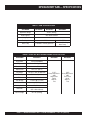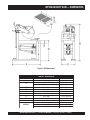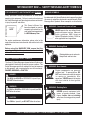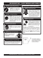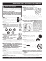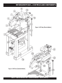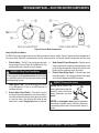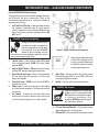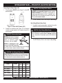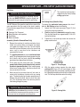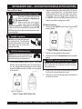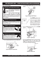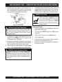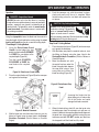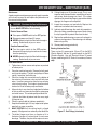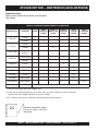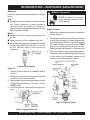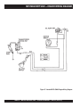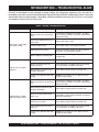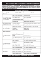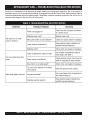
1
OPERATIONS MANUAL
MP2 SERIES
MODELS: MP2050E1,
MP2050E3, MP2090HP
MASONRY SAWS
(5 HP 1Ø ELECTRIC MOTOR)
(5 HP 3Ø ELECTRIC MOTOR)
(9.0 HP GASOLINE ENGINE)
Revision #2 (03/12/13)
THIS MANUAL MUST ACCOMPANY
THE EQUIPMENT AT ALL TIMES.
35305
P/N: 35305
Engine exhaust and some of
its constituents, and some dust created
by power sanding, sawing, grinding,
drillingandotherconstructionactivities
contains chemicals known to the State
of California to cause cancer, birth
defects and other reproductive harm.
Some examples of these chemicals are:
Leadfromlead-basedpaints.
Crystallinesilicafrombricks.
Cementandothermasonryproducts.
Arsenicandchromiumfromchemically
treatedlumber.
Your risk from these exposures varies,
depending on how often you do this type
of work. To reduce your exposure to
these chemicals: ALWAYS work in a
well ventilated area, and work with
approved safety equipment, such as
dust masks that are specially designed
to filter out microscopic particles.
PAGE 2 — MQ MP2 MASONRY SAW — OPERATION MANUAL — REV. #2 (03/12/13)
NOTE PAGE
MQ MP2 MASONRY SAW — OPERATION MANUAL — REV. #2 (3/12/13) — PAGE 3
MP2 MASONRY SAW — TABLE OF CONTENTS
MP2 MASONRY SAW
Proposition 65 Warning ............................................. 2
Table Of Contents ..................................................... 4
Parts Ordering Procedures ....................................... 5
Specifications ............................................................ 6
Dimensions ............................................................... 7
Safety Message Alert Symbols .............................. 8-9
Rules For Safe Operation .................................. 10-12
Operation and Safety Decals .................................. 13
General Information ................................................ 14
Controls and Components ................................. 16-17
Electric Motor Components .................................... 18
Engine Components ............................................... 19
Pre-Setup (Electric) ............................................ 20-22
Pre-Setup (Gasoline) ......................................... 23-24
Startup/Shutdown (Electric Motors) ........................ 25
Startup/Shutdown (Gasoline Engines) .............. 26-27
Maintenance (Saw) ............................................ 29-31
Maintenance (Engines) ...................................... 32-33
Honda Engine Wiring Diagram................................ 34
Troubleshooting (Blade) .......................................... 35
Troubleshooting (Gasoline Engine) ................... 36-37
Troubleshooting (Electric Motor) ............................. 38
Terms and Conditions of Sale — Parts ................... 40
NOTE
Specification and part number
are subject to change without
notice.
PAGE 4 — MQ MP2 MASONRY SAW — OPERATION MANUAL — REV. #2 (03/12/13)
NOTE PAGE
MQ MP2 MASONRY SAW — OPERATION MANUAL — REV. #2 (3/12/13) — PAGE 5
MP2 MASONRY SAW — SPECIFICATIONS
TABLE 1. SAW SPECIFICATIONS
Saw Model
MP2050E1
MP2050E3
MP2090HP
Approximate Weight
415 lbs. (188 Kg.)
Blade Capacity
20 in. blade maximum
Cutting Depth
8 in. with 20 in. blade
Blade Speed
2,240 RPM's
2,220 RPM's
Water Pump
115V/60Hz, Thermally protected
Mechanical/Centrifugal
Water Pump
TABLE 2. ELECTRIC MOTOR/GAS ENGINE SPECIFICATIONS
Saw Model
MP2090HP
Engine/Motor
Honda GX270QWH2
Type
4-Stroke OHV Single Cylinder
Bore & Stroke
3.0 x 2.3 in. (77 x 58 mm)
Displacement
16.5 cu. in. (270 cc)
Max Output
9.0 hp (6.7 KW) @ 3600 RPM
Fuel Tank Cap.
1.59 U.S. Gal. (6.0 liters)
Fuel
Unleaded Gasoline
Lube Oil Cap.
1.16 U.S. Qt. (1.1 liters)
Speed Control Method
Centrifugal Fly-Weight type
Star ting Method
Recoil Star t
Dimension
14.0 x 16.9 x 16.1 In.
(355 x 430 x 410 mm)
Dry Net Weight
55.1 Lbs. (25.0 Kg)
MP2050E1
MP2050E3
5 H.P.
Heavy Duty Electric
230V
Single Phase
60 Hz
Amps F.L.
12.0
5 H.P.
Heavy Duty Electric
230V
Three Phase
60 Hz
Amps F.L.
12.0
PAGE 6 — MQ MP2 MASONRY SAW — OPERATION MANUAL — REV. #2 (03/12/13)
MP2 MASONRY SAW — DIMENSIONS
Figure 1. MP2 Dimensions
TABLE 3. DIMENSIONS
REFERENCE LETTER
A
B
C
D
E
F
G
H
I
WEIGHTS
DESCRIPTION
Max Length
Max Height (Electric Models)
DIMENSION (mm)
48 In. (1219 mm)
61 In. (1549 mm)
Max Height (Gasoline Models)
68 In. (1727 mm)
Max Width
Tray Height
Tray Depth
Splash Shield Opening
Car t Length
Car t Height
Car t Width
MS 2090 HP
MS 2050 E1
MS 2050 E3
23 In. (584 mm)
34.5 In. (876 mm)
4.5 In. (114 mm)
18 In. (457 mm)
13.5 In. (343 mm)
2.5 In. (63.5 mm)
24 In. (610 mm)
526 lbs. (239 Kg)
501 lbs. (227 Kg)
526 lbs. (239 Kg)
MQ MP2 MASONRY SAW — OPERATION MANUAL — REV. #2 (3/12/13) — PAGE 7
MP2 MASONRY SAW — SAFETY MESSAGE ALERT SYMBOLS
FOR YOUR SAFETY AND THE SAFETY OF OTHERS!
Safety precautions should be followed at all times when
operating this equipment. Failure to read and understand
the Safety Messages and Operating Instructions could result
in injury to yourself and others.
NOTE
This Owner's Manual has
been developed to provide
complete instructions for the
safe and efficient operation of
the MP2 Masonry Saw.
For engine maintenance information, please refer to the
engine manufacturers instructions for data relative to its safe
operation.
HAZARD SYMBOLS
Potential hazards associated with operation of the pump will
be referenced with Hazard Symbols which appear throughout
this manual, and will be referenced in conjunction with Safety
Message Alert Symbols. Some examples are listed below:
WARNING - Guards and Covers In Place
NEVER operate the saw without blade
guards and covers in place. Adhere to
safety guidelines ANSI American
National Standards Institute, OSHA or
other applicable local regulations.
WARNING - Rotating Blade
Before using this MASONRY SAW, ensure that the
operating individual has read and understands all
instructions in this manual.
Rotating blade can cut and crush.
Keep hands and feet clear.
SAFETY MESSAGE ALERT SYMBOLS
The three (3) Safety Messages shown below will inform you
about potential hazards that could injure you or others. The
Safety Messages specifically address the level of exposure
to the operator, and are preceded by one of three words:
DANGER, WARNING, or CAUTION.
DANGER
You WILL be KILLED or SERIOUSLY injured if you
DO NOT follow directions.
WARNING
WARNING - Burn Hazards
Engine components can generate
extreme heat. To prevent burns, DO
NOT touch these areas while the engine
is running or immediately after
operations. NEVER operate the engine
with heat shields or heat guards
removed.
WARNING - Rotating Parts
You CAN be KILLED or SERIOUSLY injured if you DO
NOT follow directions.
CAUTION
You CAN be injured if you DO NOT follow directions.
NEVER operate equipment with
covers, or guards removed. Keep
fingers, hands, hair and clothing
away from all moving parts to prevent
injury.
PAGE 8 — MQ MP2 MASONRY SAW — OPERATION MANUAL — REV. #2 (03/12/13)
MP2 MASONRY SAW — SAFETY MESSAGE ALERT SYMBOLS
WARNING - Accidental Engine Starting
ALWAYS place the engine ON/
OFF switch in the OFF position,
when the saw is not in use.
HAZARD SYMBOLS - Gasoline Powered Models
WARNING - Lethal Exhaust Gases
Engine exhaust gases contain
poisonous carbon monoxide. This
gas is colorless and odorless, and
can cause death if inhaled. NEVER
operate this equipment in a confined
area or enclosed structure that does
not provide ample free flow air.
WARNING - Over Speed Conditions
NEVER tamper with the factory
settings of the engine governor or
settings. Personal injury and damage
to the engine or equipment can result
if operating in speed ranges above
maximum allowable.
WARNING - Explosive Fuel
Gasoline is extremely flammable, and
its vapors can cause an explosion if
ignited. DO NOT start the engine near
spilled fuel or combustible fluids. DO
NOT fill the fuel tank while the engine
is running or hot.
CAUTION - Respiratory Hazard
ALWAYS wear approved respiratory
protection that complies with ANSIZ87.1.
CAUTION - Sight and Hearing Hazards
DO NOT overfill tank, since spilled fuel could ignite if
it comes into contact with hot engine parts or sparks
from the ignition system. Store fuel in approved
containers, in well-ventilated areas and away from
sparks and flames. NEVER use fuel as a cleaning
agent.
ALWAYS wear approved eye and
hearing protection that complies
with ANSI-Z87.1
CAUTION - Equipment Damage Messages
Other important messages are provided throughout this
manual to help prevent damage to your concrete saw,
other property, or the surrounding environment.
NOTE
This saw, other property, or
the surrounding environment
could be damaged if you do
not follow instructions.
MQ MP2 MASONRY SAW — OPERATION MANUAL — REV. #2 (3/12/13) — PAGE 9
MP2 MASONRY SAW — RULES FOR SAFE OPERATION
WARNING - READ THIS MANUAL
Failure to follow instructions in this manual may lead to
serious injury or even death! This equipment is to be
operated by trained and qualified personnel only! This
equipment is for industrial use only.
The following safety guidelines should always be used
when operating the MP2 Masonry Saw. Unless otherwise
noted, these guidelines refer to saws with gasoline
powered engines.
Safety
■ DO NOT operate or service this
equipment before reading this entire
manual.
■ This equipment should not be operated by persons under
18 years of age.
■ NEVER operate the saw without proper
protective clothing, shatterproof glasses, steeltoed boots and other protective devices required
by the job.
Safety - Gasoline Powered Engines
■ NEVER touch the hot exhaust
manifold, muffler or cylinder. Allow
these parts to cool before servicing
the saw.
■ High Temperatures – Allow the engine to cool before adding
fuel or performing service and maintenance functions. Contact
with hot! components can cause serious burns.
■ The engine of this saw (gasoline model only) requires an
adequate free flow of cooling air. NEVER operate the saw in
any enclosed or narrow area
where free flow of the air is
restricted. If the air flow is
restricted it will cause serious
damage to the saw's engine
and may cause injury to
people. Remember the saw's
engine gives off DEADLY
carbon monoxide gas.
■ ALWAYS stop the engine before servicing, adding fuel and
oil.
■ NEVER operate this equipment when not
feeling well due to fatigue, illness or
taking medicine.
■ NEVER operate the saw under the
influence or drugs or alcohol.
■ NEVER use accessories or attachments, which are not
recommended by Multiquip for this equipment. Damage
to the equipment and/or injury to user may result.
■ Manufacturer does not assume responsibility for any
accident due to equipment modifications. Unauthorized
equipment modification will void all warranties.
■ Whenever necessary, replace nameplate, operation and
safety decals when they become difficult read.
■ ALWAYS check the saw for loosened threads or bolts
before starting.
■ NEVER operate the saw in an explosive atmosphere where
fumes are present or near combustible materials. An
explosion or fire could result causing severe bodily harm
or even death.
■ NEVER use fuel as a cleaning agent.
■ ALWAYS refuel in a well-ventilated
area, away from sparks and open
flames.
■ ALWAYS use extreme caution when
working with flammable liquids. When
refueling, stop the engine and allow it to cool.
■ NEVER smoke around or near the
machine. Fire or explosion could result from
fuel vapors, or if fuel is spilled on a hot!
engine.
■ Topping-off to filler port is dangerous, as it tends to spill fuel.
■ ALWAYS service air cleaner frequently to prevent carburetor
malfunction.
■ NEVER run the engine without the air filter. Severe engine
damage could occur. (Gasoline powered engines)
PAGE 10 — MQ MP2 MASONRY SAW — OPERATION MANUAL — REV. #2 (03/12/13)
MP2 MASONRY SAW — RULES FOR SAFE OPERATION
Safety - Electric Powered Models
■ ALWAYS connect the motor to a power source in
compliance with all local electrical codes. This must be
performed by a licenced electrician.
■ ALWAYS use only outdoor approved GROUNDED
extension cords.
■ MAKE CERTAIN the power cord/extension cord is free
from damage and that the grounding circuit is operational.
■ MAKE CERTAIN the extension cord used is intended to
be used in the environment you will be using it in. If an
extension is used, NEVER submerge the connection in
water. To reduce the risk of electrical shock, always make
water-tight connections.
■ MAKE CERTAIN the "ON/OFF" switch is in the "OFF"
position before plugging in the power cord/extension cord
to avoid accidental starting.
■ ALWAYS stop the motor before servicing. MAKE
CERTAIN the motor is stopped and turned "OFF" at the
switch, and the power cord is disconnected from the
power source.
■ Use only the guage wire and length of cord recommended
for the motor size.
■ When cutting, ALWAYS be aware of the location of the
cord.
General Safety
■ ALWAYS read, understand, and follow procedures in
Operator's Manual before attempting to operate
equipment.
■ ALWAYS be sure the operator is familiar with proper
safety precautions and operating techniques before using
the saw.
■ NEVER leave the machine unattended while running.
■ Block the unit when leaving or when using on a slope.
■ ALWAYS check to make sure that the operating area is
clear before starting the engine.
■ Maintain this equipment in a safe operating condition at
all times.
■ AVOID wearing jewelry or loose fitting clothing that may
snag on the controls or moving parts, this can cause a
serious injury.
■ ALWAYS keep clear of rotating or moving parts while
operating the saw.
■ ALWAYS store equipment properly when it is not being
used. Equipment should be stored in a clean, dry location
out of the reach of children.
■ NEVER use accessories or attachments which are not
recommended by the manufacturer for this equipment.
Damage to the equipment and/or injury to user may result.
WARNING - Clear Area Of Obstructions
ALWAYS check to make sure that the
operating area is clear before starting the
engine.
Blade Safety
■ Use appropriate blades manufactured for use on masonry
saws.
■ Always inspect blades before each
use. The blade should exhibit no
cracks, dings, or flaws in the steel
centered core and/or rim. Center
(arbor) hole must be undamaged
and true.
■ Examine blade flanges for damage, excessive wear and
cleanliness before mounting blade. Blade should fit
snugly on the shaft and against the inside/outside blade
flanges.
■ Ensure the blade is marked with an operating speed
greater than the blade shaft speed of the saw.
■ Only cut the material that is specified by the blade. Read
the specifications of the blade to ensure the proper tool
has been matched to the material being cut.
■ Always keep blade guards in place.
Exposure of the blade must not
exceed 180 degrees.
■ NEVER touch or try to stop a
moving blade with your hands.
ALWAYS keep hands clear of the
blade.
MQ MP2 MASONRY SAW — OPERATION MANUAL — REV. #2 (3/12/13) — PAGE 11
MP2 MASONRY SAW — RULES FOR SAFE OPERATION
■ Ensure that the blade does not come into contact with the
ground or surface during transportation. DO NOT drop the
blade on ground or surface.
■ The engine governor is designed to permit maximum engine
speed in a no-load condition. Speeds that exceed this limit
may cause the blade to exceed the maximum safe allowable
speed.
■ Ensure that the blade is mounted for proper operating
direction.
Saw Maintenance (Cleaning)
■ ALWAYS clean the saw before maintenance or repair.
■ DO NOT use aggressive cleaners (i.e. containing solvents).
DO NOT use high pressure water jets, aggressive detergents
or solutions and liquids with a temperature exceeding 86 F.
Use a fluff-free cloth only.
■ Use a cloth which may be lightly moistened only for removing
dust and dirt. Hard packed dirt can be removed with a soft
brush.
■ NEVER let water, cleaning liquid or vapor penetrate into the
electric motor, connectors, plugs, and switches. When
cleaning cover all apertures or openings on all electrical
components.
■ ALWAYS use a soft, low-pressure water jet and a brush to
rinse dirt and incrustations away. Be particularly careful not
to spray water on sensitive parts of of the saw (e.g. electric
motor, ON/OFF switch). Clean the motor and ON/OFF switch
by wiping with a moist cloth.
■ DO NOT rinse the bearings of the drive elements (gasoline
model only).
Saw Transportation Safety
■ Use an appropriate lifting equipment to ensure the safe
movement of the saw.
■ DO NOT use the handles as lifting points.
■ Safeguard against extreme saw attitudes relative to level. An
engine tipped to extreme angles may cause oil to gravitate
into the cylinder head making the engine start difficult.
(Gasoline powered engines)
■ NEVER transport the saw with the blade mounted.
Emergencies
■ ALWAYS know the
location of the nearest fire
extinguisher.
■ ALWAYS know the location of the
nearest and first aid kit.
■ In emergencies always know the location of the
nearest phone or keep a phone on the job site.
Also know the phone numbers of the nearest
ambulance, doctor and fire department. This
information will be invaluable in the case of an
emergency.
PAGE 12 — MQ MP2 MASONRY SAW — OPERATION MANUAL — REV. #2 (03/12/13)
MP2 MASONRY SAW — OPERATION AND SAFETY DECALS
Machine Operation And Safety Decals
The MP2 Masonry Saw is equipped with a number of safety decals (Figure 2). These decals are provided for operator safety and
maintenance information. Should any of these decals become unreadable, replacements can be obtained from your dealer.
Figure 2. MP2 Decals
MQ MP2 MASONRY SAW — OPERATION MANUAL — REV. #2 (3/12/13) — PAGE 13
MP2 MASONRY SAW — GENERAL INFORMATION
MP2 Masonry Saw
Overview of Features
The MP2 Masonry Saw is designed for vigorous wet-cutting
masonry applications. The heavy-duty steel conveyor cart and
ball bearing roller wheels ensure material stability and smooth
travel. In addition a reinforced jig-welded steel frame provides
rigidity for cutting accuracy and long service life.
■ 5 HP, 230 VAC , 60 Hz heavy duty electric motors with overload
protection.
This saw is available with either an electric motor or a gasoline
engine. Two heavy duty electric motors are available: a 5 HP
230V single phase or 5 HP 230V three phase, all with overload
protectiom.
If desired, the MP2 Masonry Saw can be configured with a 9.0
HP Honda GX270 gasoline engine.
■ 9 HP Honda GX270 gasoline engine.
■ 20-inch blade capacity provides 5-inch depth of cut.
■ Rugged steel conveyor cart for optimum stability.
■ Open back design permits capability of cutting large
materials.
■ Ergonomically designed cutting head provides operator
relief in high tempo operations.
■ Welded fork pockets for easy transportation.
All MP2 saw models include a high flow water pump, cutting jig,
water hoses and associated plumbing to enable the operator to
begin wet cutting.
■ Rubber-matted cutting table helps hold the material being
cut in place while resisting vibrations for smoother cuts with
less chipping.
Dry Cutting Applications
■ Cutting table marked in inches (ruler) for precision cuts.
The MP2 Masonry Saw masonry saw is shipped from the factory
for wet-cutting saw applications, however it can be used for drycutting saw applications (see dry-cutting saw applications in
this manual). The most important thing to remember is to
disconnect the water pump. The water pump is cooled by the
flow of water, and failure to disconnect the pump (when running
dry) will cause pump failure. NEVER! have the water pump
engaged when dry cutting applications are involved.
■ Stay-level blade guard for operator safety.
■ Rigid steel frame minimizes vibrations and assures accurate
cutting.
■ Mechanical Water Pump Kit (Gasoline Model Only)
■ Electric Submersible Water Pump Kit (Electric Models Only).
Blade Applications
This saw has been designed to incorporate the use of diamond
blades as the cutting tool. The optimum performance of this saw
is best evidenced by using 20-inch (508 mm) diamond blades
that match the material being cut. Ask your dealer, or call
Multiquip about your specific cutting application.
PAGE 14 — MQ MP2 MASONRY SAW — OPERATION MANUAL — REV. #2 (03/12/13)
NOTE PAGE
MQ MP2 MASONRY SAW — OPERATION MANUAL — REV. #2 (3/12/13) — PAGE 15
MP2 MASONRY SAW — CONTROLS AND COMPONENTS
Figure 3. MP2 Saw (Electric Models)
Figure 3. MP2 Saw (Gasoline Models)
PAGE 16 — MQ MP2 MASONRY SAW — OPERATION MANUAL — REV. #2 (03/12/13)
MP2 MASONRY SAW — CONTROLS AND COMPONENTS
Figure 3 shows the location of the basic controls or components
for the MP2 Masonry Saw. Listed below is a brief explanation of
each control or component.
1.
Ruler Backstop – When cutting, place material against
backstop. Use measurement rail (ruler) to determine where
material is to be cut.
2.
Miter Box – For angled cuts, place the lip of the miter box
on the measurement rail with the threaded thumb knob
facing you and tighten.
3.
Water Tray – When wet cutting is required, fill with clean
fresh water. Make sure the water pump is totally immersed
in water before cutting.
4.
Cutting Head Handle – Grab hold of this handle to control
the movement of the cutting head as you step on the Blade
Raise/Lower Foot Pedal.
5.
Blade Guard – Protects the user from the cutting blade.
NEVER operate the saw with the blade guard removed.
6.
Spindle Bolt/Outside Blade Flange – When mounting
of the cutting blade is required, remove the spindle bolt
and outside blade flange. Align cutting blade with inside
flange arbor and reassemble spindle and outside blade
flange.
7.
8.
9.
10.
11.
12.
13.
14.
Power ON/OFF Box – This box is used on electric models
saws only. To turn on the saw place in the ON (I) position.
Place in the OFF (0) position to shut-down the saw.
V-belt Cover – Remove this cover to access the drive
V-belt. NEVER operate the saw with the V-belt cover
removed.
Electric Motor/Conduit Box– This unit uses 2 different
types of electric motors and voltages (see Table 2). Plug
the water pump (electric models only) power cord into the
AC receptacle located on the conduit box.
Mounting Plate – Supports the electric motor/gasoline
engine. Plate has slotted holes for horizontal (right-side)
and vertical (left-side) adjustment of cutting head.
Mounting Plate Handle – Grip this handle (rear) to lift the
mounting plate.
Tie Rod – The tie rod length has been set at the factory for
best blade guard position for the majority of the cutting that
will be done.
Splash Guard – Keeps water and debris from leaving the
water tray.
Stopper – Place stopper in tray when filling with water.
15. Electric Water Pump – For best results place the pump
between the splash shield and the rear of the water tray.
This is for electric models only. Plug water pump power
cord into AC receptacle on electric motor conduit box.
NEVER run pump dry. Pump must be immersed in water.
16. Blade Raise/Lower Crank Handle – Use this handle to
set the maximum cutting depth of the MP2 Masonry Saw.
Turn clock-wise to LOWER the blade. Turn counter-clockwise to RAISE the blade.
17. Blade Raise/Lower Foot Pedal – Step on the pedal to
lower the blade for cutting. Gently step off the pedal to raise
the blade when finished cutting.
18. Spring Tensioner – Connects to the foot pedal bar to allow
for an easy up and down movement of the mounting plate
and blade.
19. Forklift Pockets – Use to easily move the MP2 Masonry
Saw from one location to another. When moving the saw,
ensure that the forks pass completely through the pockets
on both sides of the machine before attempting to lift the
MP2.
20. Mechanical Water Pump – This pump is used on gasoline
models only. Saw is shipped from the factor for wet cutting
applications (pump handle down). Place pump handle
upwards to disengage pump. NEVER run pump dry.
21. Engine – The gasoline model saws uses a 9.0 HP Honda
GX270, 4-stroke, OHV, single cylinder, air cooled gasoline
engine.
22. V-belt Cover (Gasoline Only) – Remove this cover to
access the engine shaft-side V-belt. NEVER operate the
saw with the V-belt cover removed.
23. Water Lines – Replace the clear vinyl tubing water lines
when they become brittle, worn or clogged. Water kits are
available through your dealer.
24. Strainer – For best results place the strainer between the
splash shield and the rear of the water tray. This is for
gasoline models only. NEVER run pump dry. Strainer must
be immersed in water.
25. Priming Bulb – Squeeze this bulb to prime the mechanical
water pump (gasoline models only).
26. Blade Wrench – Use this tool to mount and remove cutting
blade.
MQ MP2 MASONRY SAW — OPERATION MANUAL — REV. #2 (3/12/13) — PAGE 17
MP2 MASONRY SAW — ELECTRIC MOTOR COMPONENTS
Figure 4. Electric Motor Components
Heavy Duty Electric Motors
The MP2 Saw can be equipped with several different models of electric motors. Figure 4 shows the basic components of
the electric motor. Refer to the manufacturers electric motor manual for instructions & details of operation and servicing.
1.
Electric Motor – The MP2 saw can be operated with
either a Single Phase or Three Phase 230V motor. Only
qualified electricians should service the motor.
WARNING - Wiring Three Phase Motors
All saws equiped with three phase motors should be wired
by a qualified electrician and correct motor rotation verified
before operating the saw.
4.
Water Pump AC Power Receptacle – Plug the electric
water pump into this receptacle to provide power to the
pump during saw operation. Unplug the electric water
pump from this receptacle when dry cutting.
5.
Electric Motor Wiring Pigtail – The saw motor ships
with cable "pigtails." Have an licenced electrician supply
and install the appropriate NEMA connector.
DANGER - Electrocution Hazard
2.
Power ON/OFF Box – To turn on the saw, place switch
in the ON position. Place in the OFF position to
shutdown the saw.
3.
Electric Motor Reset Switch – This switch is part of
the thermal overload protection for the electric motor. If
the motor overheats and shuts down, press this switch
to reset the motor, after allowing the motor to cool
down.This is used on Single phase electric saws only.
NEVER grab or touch a live
power cord with wet hands, the
possibility exists of electrical
shock, ectrocution, and even
death!
NEVER use a damaged or worn extension cable when
connecting to a power source. Defective cables may
cause damage to the saw's electric motor or electrical
shock.
PAGE 18 — MQ MP2 MASONRY SAW — OPERATION MANUAL — REV. #2 (03/12/13)
MP2 MASONRY SAW — GASOLINE ENGINE COMPONENTS
Honda GX270QWH2 Gasoline Engine
The engine (Figure 5) must be checked for proper lubrication
and filled with fuel prior to operation. Refer to the
manufacturers engine manual for instructions & details of
operation and servicing.
1. Fuel Tank/Fuel Filler Cap – Holds unleaded gasoline.
For additional information refer to engine owner's
manual. Remove this cap to add unleaded gasoline to
the fuel tank. Make sure cap is tightened securely. DO
NOT over fill.
DANGER - Explosive Fuel Hazard
Adding fuel to the tank should be done
only when the engine is stopped and
has had an opportunity to cool down.
In the event of a fuel spill, DO NOT
attempt to start the engine until the
fuel residue has been completely wiped up, and the
area surrounding the engine is dry.
Figure 5. Engine Controls and Components
NOTE
Operating the engine without an
air filter, with a damaged air filter,
or a filter in need of replacement
will allow dirt to enter the engine,
causing rapid engine wear.
2.
Throttle Lever – Used to adjust engine RPM speed
(lever advanced forward SLOW, lever back toward
operator FAST).
3.
Engine ON/OFF Switch – ON position permits engine
starting, OFF position stops engine operations.
4.
Recoil Starter (pull rope) – Manual-starting method.
Pull the starter grip until resistance is felt, then pull
briskly and smoothly.
8.
Spark Plug – Provides spark to the ignition system.
Set spark plug gap to 0.6 - 0.7 mm (0.028 - 0.031 inch)
Clean spark plug once a month.
5.
Fuel Valve Lever – OPEN to let fuel flow, CLOSE to
stop the flow of fuel.
9.
Muffler – Used to reduce noise and emissions
6.
Choke Lever – Used in the starting of a cold engine,
or in cold weather conditions. The choke enriches the
fuel mixture.
7.
Air Cleaner – Prevents dirt and other debris from
entering the fuel system. Remove wing-nut on top of
air filter cannister to gain access to filter element.
DANGER - Burn Hazard
Engine components can generate
extreme heat. To prevent burns, DO
NOT touch these areas while the engine
is running or immediately after
operating. NEVER operate the engine
with the muffler removed.
10. Oil Level Cap and Dipstick – Check engine oil with
engine stopped and in a level position.
11. Oil Drain Bolt – Drain used oil while the engine is warm.
MQ MP2 MASONRY SAW — OPERATION MANUAL — REV. #2 (3/12/13) — PAGE 19
MP2 MASONRY SAW — PRE-SETUP (ELECTRIC MOTORS)
Pre-Setup
5.
WARNING - Shut-down Saw for Cleaning
Insert the water pump power plug into the outlet
receptacle on the electric motor conduit box as shown
in Figure 7.
Whenever cleaning, adjusting or lubricating any part
of the saw, MAKE CERTAIN to place the power ON/
OFF switch in the OFF position and disconnect the
plug from the power source.
Assembly (Electric Powered Saws Only)
1.
2.
3.
4.
Remove the MP2 Masonry Saw from its container and
place it on a stable, level surface. Make sure location
you choose can support the weight of the saw. The
saw location should be rigid and stationary so that the
saw will not move, sag, or sway due to the vibrations
and movements of the saw.
Figure 7. Water Pump Power Connection
For three-phase motors, you may be required to install
a plug on the end of the water pump power cable, which
should have 3 wires exposed. Have a qualified electrician
install a male plug that has bee properly rated for the
equipment(230V).
Connect the barb fitting to the water pump. Attach the
clear plastic water hose (Figure 6) coming from the blade
guard to the water pump.
Fill the water tray with clean fresh water. The water
pump intake must always be fully covered by water.
Also, keep the pump intake free of sludge, debris and
other materials that may accumulate in the tray.
Make certain that the water hose will not come in
contact with the blade or interfere with any moving
parts. The best location for the water pump/strainer is
between the splash shield and the rear of the water
tray. This will prevent some of the abrasive particles
from flowing through the pump.
Figure 6. Water Tray/Water Pump
Once a plug has been installed, insert the power plug
into the receptacle plug cord attached to the motor.
(Electric Motor Components, item 3)
Conveyor Cart Placement
1.
Place the conveyor cart across the water tray as shown
in Figure 8. Align the wheels of the cart with the outer
edge of the water tray. Push the cart back and forth, it
should move freely in both directions.
Figure 8. Conveyor Cart Placement
PAGE 20 — MQ MP2 MASONRY SAW — OPERATION MANUAL — REV. #2 (03/12/13)
MP2 MASONRY SAW — PRE-SETUP (ELECTRIC MOTORS)
WARNING - Inspect the Blade before Cutting
Failure to thoroughly inspect the
blade for operational safety could
result in damage to the blades or the
saw and may cause serious injury
to the user or others in the operating
area. Inspect the blade flanges and
shaft for damage before installing the
blade.
Saw Blades
Diamondback Diamond Blades ™ are recommended for
your saw. Ask your MQ dealer about your specific cutting
application.
Saw Blade Definitions (Figure 9)
1. Stress Relief Holes (Gullets) - Check the steel core
for cracks that may have propagated from the slots and/
or gullets. Cracks indicate
extreme fatigue failure and
if sawing continues,
catastrophic failure will
occur.
Figure 9. Diamond Blade
2. Edge of the Steel Core - Check the diameter edge for
discoloration (blue oxidation) indicating an overheating
condition caused by insufficient cooling water/air.
Overheating of blades may lead to loss of core tension
and/or increase the possibility for blade failure. Make
sure the steel core's width is uniform about the rim of
the blade, and not succumbing to an "under-cutting"
condition brought about by highly abrasive material or
improper under-cutting core protection.
5. Specifications - Ensure that the blade specifications,
size, and diameter properly match up to sawing
operations. Utilizing a blade not matched properly to
the task may result in poor performance and/or blade
damage.
6. Arbor Hole - It is essential that the arbor hole diameter
properly matches the blade, and that it is free from
distortion. Correct blade flanges (collars) must be used.
The inside face of the flanges must be clean and free of
debris. An out-of-round arbor condition will cause
damage to the blade and the saw.
7. Max RPM - This RPM reference is the maximum safe
operating speed for the blade selected. NEVER exceed
the max RPM on the diamond blade. Exceeding the
maximum RPM is dangerous and may cause poor
performance and may damage the blade.
Blade Installation
1.
Use the blade bolt wrench (Figure 10) supplied with the
saw to install the cutting blade.
2.
Ensure the capacity of the blade guard matches the
diameter of your cutting blade.
3.
Using the blade nut wrench, remove the blade shaft bolt
and outside blade flange. Install the cutting blade onto
the inside blade flange arbor. Re-install the outside blade
flange and blade shaft bolt. Tighten securely. DO NOT over
tighten.
3. Directional Arrow - Ensure that the blade is oriented
properly on the blade shaft for sawing. Reference the
directional arrow on the blade and place it so the direction
of rotation "downcuts" with the turn of the shaft.
4. Diamond Segment or Rim - Ensure there are no
cracks, dings, or missing portions of the diamond
segment/rim. DO NOT use a blade that is missing a
segment or a portion of the rim. Damaged and /or
missing segments/rims may cause damage to your saw
or injury to the user or others in the operating area.
Figure 10. Blade Placement
MQ MP2 MASONRY SAW — OPERATION MANUAL — REV. #2 (3/12/13) — PAGE 21
MP2 MASONRY SAW — PRE-SETUP (ELECTRIC MOTORS)
Connecting the Power (Figure 10)
1.
CAUTION - Grounding Electric Motors
Place the power ON/OFF switch (Figure 11) in the OFF
position (down).
ALWAYS use a grounded (3-wire) extension cord and
MAKE CERTAIN that the motor is connected to a
properly grounded electric circuit. If possible use a
ground fault circuit interrupter to protect the operator
from possible electric shock.
4.
The MP2 Masonry Saw is now ready for wet cutting.
Dry Cutting (Electric Saws Only)
1.
Figure 11. Power ON/OFF Switch (OFF)
2.
Connect an extension cord (Figure 13) of adequate
current carrying capacity to the power plug on the
electric motor.
DANGER - Electrocution Hazard
NEVER grab or touch a live power
cord with wet hands, the possibility
exists of electrical shock,
ectrocution, and even death!
Un-plug the water pump power cord from the outlet
receptacle on the electric motor conduit box.
CAUTION - Dry Cutting & Water Pump
NEVER dry cut with the pump connected to a AC power
source. Running the pump dry will damage the pump.
Always disconnect the pump's power cord when dry
cutting.
2.
The MP2 Masonry Saw is now ready for dry cutting.
NEVER use a damaged or worn
extension cable when connecting
to a power source. Defective cables may cause damage
to the saw's electric motor or electrical shock.
CAUTION - Dry Cutting & Water Pump
MAKE CERTAIN that the correct size extension cord
is used. Undersize wires will burn out motors. Use Table
4 to determine the correct extension cord size.
TABLE 4. EXTENSION CORD SIZES
MOTOR
VOLTAGE
50'
LONG
75'
LONG
100'
LONG
5HP - SINGLE PHASE
230
No. 10
No. 8
No. 6
5HP - 3 PHASE
230
No. 12
No. 10
No.. 8
5HP - 3 PHASE
460
No. 14
No. 12
No. 10
7.5HP - 3 PHASE
230
No. 10
No. 8
No. 6
7.5HP - 3 PHASE
460
No. 12
No. 10
No. 8
PAGE 22 — MQ MP2 MASONRY SAW — OPERATION MANUAL — REV. #2 (03/12/13)
MP2 MASONRY SAW — PRE-SETUP (GASOLINE ENGINE)
Pre-Setup
NOTE
CAUTION - Shut-down Saw for Cleaning
Whenever cleaning, adjusting or lubricating any part
of the saw, MAKE CERTAIN to stop the engine and
disconnect the spark plug wire from the spark plug.
The mechanical water pump is
shipped from the factory for dry
cutting applications.
Wet Cutting Setup (Gasoline Only)
The MP2 Masonry Saw gasoline model utilizes some of the
same procedures that are used for the electric models.
Please reference pages 20 and 21 for the below referenced
procedures:
To connect the mechanical water pump to the drive Vbelts for Wet Cutting, perform the following:
1.
Loosen the 2 hex head cap screws (Figure 12) that
secure the pump mount bracket.
■
■
■
■
2.
Push the pump handle downward to engage the pump.
The drive belt should have approximately 1/8 to 3/16
inch belt deflection.
Tighten the 2 hex head cap screws that secure the
pump mount bracket.
Conveyor Cart Placement
Blade Selection and Inspection
Saw Blades
Blade Installation
Assembly (Gasoline Powered Saws Only)
1.
Remove the saw from its container and place it on a
stable, level surface. Make sure location you choose
can support the weight of the saw. The saw location
should be rigid and stationary so that the saw will not
move, sag, or sway due to the vibrations and
movements of the saw.
2.
The gasoline powered saw uses a mechanical water
pump. This pump operates by drawing power from the
drive V-belts, and has been adjusted dry cutting
operation when shipped from the factory.
3.
Fill the water tray with clean fresh water. The water
pump intake (strainer) must always be fully covered
by water to operate effectively. Also, keep the pump
intake free of sludge, debris and other materials that
may accumulate in the tray.
4.
Make certain that the water hose will not come in
contact with the blade or interfere with any moving
parts. The best location for the water pump/strainer is
between the splash shield and the rear of the water
tray. This will prevent some of the abrasive particles
from flowing through the pump.
3.
Figure 12. Pump Engage
4.
With the engine running, squeeze the water pump
priming bulb (Figure 13) until water begins to flow
through the water lines. If the pump is working correctly,
the cutting blade should be covered with a steady water
mist. This will keep the blade cool while cutting.
CAUTION - Water Strainer Placement
ALWAYS position the strainer in the water tray in a manner
that will allow the free movement of the conveyor cart, and
clearance from the cutting blade and cutting action.
Figure 13. Priming Bulb
MQ MP2 MASONRY SAW — OPERATION MANUAL — REV. #2 (3/12/13) — PAGE 23
MP2 MASONRY SAW — PRE-SETUP (GASOLINE ENGINE)
Dry Cutting Setup (Gasoline Only)
CAUTION - Dry Cutting
ALWAYS use the water feed system unless special
dry cut blades are being used. If dry cutting is required
disconnect water pump.
To disconnect the mechanical water pump from the drive
V-belts for Dry Cutting, perform the following:
1.
Loosen the 2 hex head cap screws (Figure 14) that
secure the pump mount bracket.
2.
Pull the pump handle upward to disengage the pump.
Tighten the 2 hex head cap screws that secure the
pump mount bracket.
3.
Figure 15. Engine Oil Dipstick (Removal)
3. Insert and remove the dipstick without screwing it into
the filler neck. Check the oil level shown on the dipstick.
UPPER
4. If the oil level is low
(Figure 16), fill to the edge
of the oil filler hole with the
recommended oil type
(Table 5). Maximum oil
capacity is 1.16 quarts (1.1
LOWER
liters)
Figure 16. Engine Oil Dipstick (Oil Level)
TABLE 5. OIL TYPE
Figure 14. Pump Disengage
Before Starting
1.
2.
3.
4.
5.
Read safety instructions at the
beginning of manual.
Clean the saw, removing dirt and
dust, particularly the engine cooling
air inlet, carburetor and air cleaner.
Check the air filter for dirt and dust. If air filter is dirty,
replace air filter with a new one as required.
Check carburetor for external dirt and dust. Clean with
dry compressed air.
Check fastening nuts and bolts for tightness.
Season
Temperature
Oil Type
Summer
25°C or Higher
SAE 10W-30
Spring/Fall
25°C~10°C
SAE 10W-30/20
Winter
0°C or Lower
SAE 10W-10
DANGER- -Explosive
ExplosiveFuel
Fuel
CAUTION
Motor fuels are highly flammable and
can be dangerous if mishandled. DO
NOT smoke while refueling. DO NOT
attempt to refuel the pump if the engine
is hot! or running.
Fuel Check
Engine Oil Check
1. Remove the gasoline cap located on top of fuel tank.
1.
To check the engine oil level, place the saw on a secure
level surface with the engine stopped.
2. Visually inspect to see if the fuel level is low. If fuel is
low, replenish with unleaded fuel.
2.
Remove the filler dipstick from the engine oil filler hole
(Figure 15) and wipe clean.
3. When refueling, be sure to use a strainer for filtration. DO
NOT top-off fuel. Wipe up any spilled fuel immediately!
PAGE 24 — MQ MP2 MASONRY SAW — OPERATION MANUAL — REV. #2 (03/12/13)
MP2 MASONRY SAW — STARTUP/SHUTDOWN (ELECTRIC MOTORS)
Start-up (Electric Motor)
2.
CAUTION - Read this Manual before Starting!
Read and fully understand this manual
before starting or attempting to
operate the saw.
Before starting the saw's electric
motor make sure that the Safety,
General Information, Inspection and Pre-setup
sections have been completed and understood. DO
NOT proceed until the above mentioned sections have
been completed.
Avoid overloading the motor when cutting. The electric
motors are protected with a manual-reset thermal
overload switch that will turn the saw off if the motor is
overheated. In the event that the switch is tripped, turn
the ON/OFF switch to the OFF position and allow the
motor to cool before attempting to restart.
Shutdown Procedure
1.
Place the power ON/OFF switch (Figure 18) in the OFF
position (down).
DANGER - Amputation
Hazard
NEVER place hands and fingers near
the cutting blade. The possibility
exists of severe bodily harm if hands
and fingers come in contact with
rotating saw blade.
Figure 18. Power ON/OFF Switch (OFF)
CAUTION - Blade Guard Safety
ALWAYS ensure that the cutting blade has
been mounted correctly and that it is raised
above the surface you are about to cut.
1.
Turn the power ON/OFF switch (Figure 17) to the ON
position with the blade away from the material to be
cut, the cutting blade should begin to rotate. Before
cutting remember to follow all safety rules referenced
in this manual.
2.
3.
Wait for the cutting blade to stop rotating.
Disconnect the saw's AC power cord from the power
source.
CAUTION - Leaving the Saw Unattended
NEVER leave the saw connected to a power source
when unattended. This will prevent accidental starting
and potential injury.
4.
Using a soft cloth, clean any excess debris or residue
that may have accumulated on the saw.
5.
Store saw in a clean dry location where it will be out of
the reach of children.
Figure 17. Power ON/OFF Switch (ON)
MQ MP2 MASONRY SAW — OPERATION MANUAL — REV. #2 (3/12/13) — PAGE 25
MP2 MASONRY SAW — STARTUP/SHUTDOWN (GASOLINE ENGINE)
Start-up Gasoline Engine
2. Place the Engine ON/OFF switch (Figure 20) in the ON
position.
CAUTION - Read this Manual before Starting!
Read and fully understand this manual
before starting or attempting to
operate the saw.
Before starting the saw's electric
motor make sure that the Safety,
General Information, Inspection and Pre-setup
sections have been completed and understood. DO
NOT proceed until the above mentioned sections have
been completed.
Figure 20. Engine ON/OFF Switch
CAUTION - Dry Cutting Precautions
ALWAYS use the water feed system unless special
dry cut blades are being used. If dry cutting is required
disconnect water pump.
WARNING - Amputation Hazard
NEVER place hands and fingers near
the cutting blade. The possibility exist
of severe bodily harm if hands and
fingers come in contact with rotating
saw blade.
NOTE
The CLOSED position of the
choke lever enriches the fuel
mixture for starting a COLD
engine. The OPEN position
provides the correct fuel mixture
for normal operation after starting,
and for restarting a warm engine.
3. Place the Choke Lever (Figure 21) in the CLOSED
position.
CAUTION - Blade Guard Safety
ALWAYS ensure that the cutting blade has
been mounted correctly and that it is raised
above the surface you are about to cut.
1. Place the fuel valve lever (Figure 19) to the ON position.
Figure 21. Choke Lever
4. Rotate the throttle lever (Figure 22) halfway between
fast and slow for starting. All cutting is done at full
throttle. The engine governor speed is factory set to
ensure optimum blade operating speeds.
Figure 19. Engine Fuel Valve Lever
Figure 22. Throttle Lever
PAGE 26 — MQ MP2 MASONRY SAW — OPERATION MANUAL — REV. #2 (03/12/13)
MP2 MASONRY SAW — STARTUP/SHUTDOWN (GASOLINE ENGINE)
5. Grasp the starter grip (Figure 23) and slowly pull it out.
The resistance becomes the hardest at a certain position, corresponding to the compression point. Pull the
starter grip briskly and smoothly for starting.
9.
Avoid overloading the engine when cutting. In the event
that the engine becomes overloaded, turn the engine
ON/OFF switch to the OFF position (Figure 25) and
allow the engine to cool before attempting to restart.
WARNING - Burn Hazard
Engine components can generate extreme
heat. To prevent burns, DO NOT touch these
areas while the engine is running or
immediately after operations. NEVER
operate the engine with heat shields or heat
guards removed.
Figure 23. Starter Grip
CAUTION - Engine Starter Rope Safety
DO NOT pull the starter rope all the way to the end. DO
NOT release the starter rope after pulling. Allow it to
rewind as soon as possible. Failure to do so could
damage your engine.
6. If the engine has started, slowly return the choke lever
(Figure 21) to the OPEN position. If the engine has not
started repeat steps 1 through 5.
7. Before the saw is placed into operation, run the engine
for several minutes. Check for fuel leaks, and noises that
would associate with loose guards and/or covers.
8. Gradually move the engine throttle lever toward the fast
position. (All cutting should be done at full throttle).
Stopping the Engine
1. Set the engine throttle lever to slow speed and let the
engine idle for 3-5 minutes.
2.
Turn the engine ON/OFF switch to the OFF position
(Figure 25).
3.
Place the fuel valve lever in the closed position.
4.
Let the engine cool.
5.
Using a soft cloth, clean any excess debris or residue
that may have accumulated on the saw.
6.
Store saw in a clean dry location where it will be out of
the reach of children.
WARNING - Engine Speed when Cutting
ALWAYS cut with the saw at FULL THROTTLE.
Attempting to cut with the saw at less than full throttle
could cause the blade to bind or stop abruptly in the
slab resulting in serious injury to the operator or others
in the area.
MQ MP2 MASONRY SAW — OPERATION MANUAL — REV. #2 (3/12/13) — PAGE 27
MP2 MASONRY SAW — OPERATION
Operation
4.
DANGER - Amputation Hazard
ALWAYS be alert to the fact that there is a rotating
blade on the saw and be extremely aware of your body
position - especially your hands in relationship to the
rotating blade. The possibility exists of severe bodily
harm even death if your body comes in contact with
the rotating saw blade.
The MP2 Masonry Saw has two methods availible for cutting:
Using the step pedal to lower the blade into the material or
fixing the height of the blade before cutting using the raise/
lower crank handle to allow for a constant cutting depth.
"Fixed Height" Cutting Method
1.
Using the Raise/Lower Crank
Handle, located above the step
pedal, turn the handle CLOCKWISE
to LOWER the saw blade to the
required depth (Figure 24).
Turn the handle COUNTERCLOCKWISE to RAISE the
saw blade to the required
depth.
CAUTION - Dry Cutting Guidelines
NEVER lift the blade guard while
the blade is rotating. The possibility
exists of severe bodily harm if
fingers or hands come in contact
with the rotating saw blade. Wait for the blade to stop
rotating before lifting the blade guard.
"Step Pedal" Cutting Method
1.
Place the material to be cut (Figure 25) on the conveyor
cart against the backstop.
2.
With the blade away from the material to be cut, start
the Motor (or Engine) using the steps listed in the
Startup/Shutdown Procedure (Electric Motors or
Gasoline Engine).
3.
Move the conveyor cart, with
the matrial in place, under the
blade. Using your foot, depress
the step pedal using a slow
even pressure to lower the
blade for cutting (Figure 26).
Figure 24. Raise/Lower Crank Handle
2.
Push the conveyor cart, with the material in place,
slowly and evenly until the cut is complete. When
finished cutting, move the cart back and remove the
cut pieces.
Place the material to be cut (Figure 25) on the conveyor
cart against the backstop.
Figure 26. Raise/Lower Step
Pedal
NOTE
4.
Figure 25. Material Placement
3.
With the blade away from the material to be cut, start the
Motor (or Engine) using the steps listed in the Startup/
Shutdown Procedure (Electric Motors or Gasoline
Engine).
Jamming the blade into the
object being cut will reduce the
life of the blade and could
damage the blade or material.
When finished cutting, slowly lift your foot up to raise
the blade away from the conveyor cart and your cut
material. Hold on to the mounting plate handle to prevent
the plate from rising rapidly, possibly causing the saw
to become unstable. DO NOT remove your foot from
the step pedal until the blade has fully raised.
PAGE 28 — MQ MP2 MASONRY SAW — OPERATION MANUAL — REV. #2 (03/12/13)
MP2 MASONRY SAW — MAINTENANCE (SAW)
Maintenance
A good preventive maintenance program of regular inspection
and care will increase life and improve the performance of
the saw and cutting blades.
WARNING - Shut-down the Saw for Maintenance
Whenever cleaning, adjusting, or lubricating any part of
the saw, MAKE CERTAIN to do the following:
Electric Powered Saws
■ Place power ON/OFF switch to the OFF position.
■ Disconnect power cord from AC source.
■ NEVER attempt to check the V-belt with the engine
running. Severe bodily injury can occur.
Gasoline Powered Saws
■ Turn the engine switch to the OFF position,
disconnect the spark plug wire and secure it away
from the spark plug.
■ NEVER attempt to check the V-belt with the engine
running. Severe bodily injury can occur.
10. Cutting blades must fit the arbor snugly. This is very
important with diamond blades as pounding will occur
and serious blade damage can result. If the arbor
shoulder of the inner blade flange is grooved from blade
slippage, the flange must be replaced.
11. Inspect the conveyor cart periodically. Replace the
wood insert and wheels when necessary.
12. Lubricate spindle bearings after each day's operation.
When dry cutting, grease bearings several times during
the day's operation to protect them from the dust.
13. Replace the spindle bearings as soon as they begin to
make any strange noises. Worn bearings can destroy
blades very quickly.
14. Grease pivot bearings periodically.
Bearing Lubrication Care
There are two (2) grease points (Figure 27) for the MP2
(Electric Motors) and four (4) grease points for the MP2
(Gasoline Engine). Use only Premium Lithium 12 based
Grease, conforming to NLG1 Grade #1 consistency. Grease
daily.
Basic Maintenance
1.
2.
3.
4.
5.
6.
7.
8.
9.
Tighten loose nuts or screws and replace any cracked
or broken parts.
Clean the machine frequently. Remove the belt guard
and clean the pulleys. The belts and pulleys will wear
rapidly if excessive dust builds up.
Clean the sludge that accumulates on the bottom of
the water tray at least once a day and refill with clean
water. It may be necessary to clean the tray out twice
a day in heavy cutting. The sludge is abrasive and will
shorten the life of the water pump and blades.
After each day's use, clean the sludge from the bottom
of the tray and run clean water through the water pump
and water hoses. This extends pump and blade life.
Lubricate the blade adjustment rod after every eight
(8) hours of use.
Check the spindle bolt for tightness periodically.
Keep the drive belts tight. It is very important to replace
worn belts as soon as possible.
MAKE CERTAIN that the cutting head is aligned
properly. Misalignment can adversely affect blade life.
Figure 27. Zerk Fittings (Lubrication)
The blade flanges must have a diameter of 4 in.
Undersize flanges will reduce blade life and cause
breakage. Therefore, they should be replace at once.
MQ MP2 MASONRY SAW — OPERATION MANUAL — REV. #2 (3/12/13) — PAGE 29
MP2 MASONRY SAW — MAINTENANCE (SAW)
Adjust Belt Tension (Gasoline Powered Saws)
1. Remove engine-to-jackshaft and jackshaft-to-bladeshaft
belt guards.
3
When belt tension is correct, pulleys are aligned, and
belts are parallel, tighten jackshaft mounting bolts and
adjuster screw jam nuts.
2. Check for proper belt tension on jackshaft-to-bladeshaft 4. Check for proper engine-to-jackshaft belt tension (4-5
lbs with 1/8" deflection at mid-point between pulleys.)
belts and engine-to-jackshaft belts.
4-5 lbs of force applied to the mid-point between jackshaft 5. Adjust engine adjuster bolts to apply proper tension while
maintaining pulley alignment and belt parallelism. Check
and bladeshaft pulleys should deflect the belt
pulley alignment and parallelism with a straight edge
approximately 3/16" on a used belt.
from jackshaft pulley to engine pulley.
4-5 lbs of force applied to the mid-point between engine
and jackshaft pulleys should deflect the belt 6. When proper belt tension and parallelism have been
achieved, tighten engine mounting bolts.
approximately 1/8".
Reinstall belt guards. Test saw operation.
To adjust engine-to-jackshaft belts only:
1. Loosen engine mounting bolts.
2. Adjust engine adjusting nuts to apply proper tension while
maintaining pulley alignment and belt parallelism. Check
pulley alignment and parallelism with a straight edge
from jackshaft pulley to engine pulley.
NOTE
It is very important that the
jackshaft and blade arbor remain
parallel to each other.
This can be accomplished by using
the adjusting bolt located on the engine mounting plate to
help keep the jackshaft from cocking.
3. When proper belt tension and parallelism have been
achieved, tighten engine mounting bolts.
To adjust jackshaft-to-bladeshaft belt:
If the jackshaft-to-bladeshaft belt requires adjustment, it will
also be necessary to adjust the engine-to-jackshaft belts.
Adjust Belt Tension (Electric Powered Saws)
1. Remove the three belt guard screws securing the belt
guard to the frame and remove the belt guard.
2. Loosen the four motor mounting bolts.
3. To increase belt tension, tighten the two adjusting nuts
on the back of the motor plate.
Proper belt tension is 4-5 lbs. of force with approximately
3/16" of belt deflection measured at a point midway
between the pulleys.
4. Adjust motor adjusting nuts to apply proper tension while
maintaining pulley alignment and belt parallelism. Check
pulley alignment and parallelism with a straight edge
from motor pulley to bladeshaft pulley.
5. When proper belt tension and parallelism have been
achieved, tighten engine mounting bolts and re-attach
the belt guard.
1. Loosen the 4 jackshaft mounting bolts, the 4 engine
mounting bolts, and the jackshaft adjuster screw jam
nuts (Loosen the mounting bolts only enough for the
jackshaft and the engine to slide easily.)
2. Adjust jackshaft-to-bladeshaft belt first. To increase
tension, tighten adjuster on bladeshaft belt side. To help
maintain belt parallelism, loosen the jackshaft adjuster
screw on the engine side the same number of turns that
the bladeshaft side adjuster screw was tightened. Using
a straight edge on the bladeshaft pulley to the jackshaft
pulley, check for pulley alignment and belt parallelism.
PAGE 30 — MQ MP2 MASONRY SAW — OPERATION MANUAL — REV. #2 (03/12/13)
MP2 MASONRY SAW — MAINTENANCE (SAW)
Cutting Head Alignment (Blade)
Checking Vertical Cutting Head Alignment:
When cutting with the MP2 Masonry Saw, make certain the
cutting head is properly aligned horizontally and vertically
with the conveyor cart. Misalignment can adversely affect
blade life.
Use the following procedures to check the vertical cutting
head alightment. The MP2 Masonry Saw saw is factory
shimmed to ensure proper vertical alignment. Should the
cutting head become vertically misaligned, contact your
local authorized service center to have the cutting head
realigned.
Horizontal Cutting Head Alignment:
1. Loosen the set screws (Motor Plate & Blade Guard
Assy., Item 9) for the engine mount bearings.
2. Adjust the position of the cutting head horizontally until
the blade is positioned within the middle of the cutting
groove (Figure 28).
3. Slide the coveyor cart forward and backward on the tray
to ensure that no part of the blade comes into contact
with the groove. If the blade touches the side of the cart
at any time, the cutting head is out of alignment. Repeat
steps 1-3 until corrected.
4. Tighten the set screws.
CAUTION - Cutting Head Alignment
It is very important that the jackshaft and blade shaft
remain parallel to each other. Self-alignment of the cutting
head could result in damage to your material, machine or
bodily injury.
1. Using a square or other straight edge device, check the
vertical alignment of the blade by placing the bottom of
the square on the conveyor cart and the side of the
square against the blade (Figure 29).
2. If a gap exists between any part of the blade and square,
the cutting head is out of alignment.
Figure 28. Cutting Head Alignment (Horizontal)
Figure 29. Cutting Head Alignment (Vertical)
MQ MP2 MASONRY SAW — OPERATION MANUAL — REV. #2 (3/12/13) — PAGE 31
MP2 MASONRY SAW — MAINTENANCE (GASOLINE ENGINE)
Engine Maintenance
Perform engine maintenance procedures as referenced by
Table 6 below:
TABLE 6. ENGINE MAINTENANCE SCHEDULE
DESCRIPTION (3)
OPERATION
BEFORE
CHECK
X
FIRST
MONTH OR
10 HRS.
EVERY 3
MONTHS OR
25 HRS.
EVERY 6
MONTHS OR
50 HRS.
EVERY
YEAR OR
100 HRS.
EVERY
2 YEARS OR
200 HRS.
Engine Oil
CHANGE
CHECK
X
X
Air Cleaner
CHANGE
All Nuts & Bolts
Re-tighten If
Necessary
X (1)
X
CHECK-CLEAN
X
Spark Plug
REPLACE
X
Cooling Fins
CHECK
X
Spark Arrester
CLEAN
X
Fuel Tank
CLEAN
X
Fuel Filter
CHECK
X
Idle Speed
CHECK-ADJUST
X (2)
Valve Clearance
CHECK-ADJUST
Fuel lines
CHECK
X (2)
Every 2 years (replace if necessary) (2)
(1) Service more frequently when used in DUSTY areas.
(2) These items should be serviced by your servic dealer, unless you have the proper tools and are mechanically
proficient. Refer to the HONDA shop Manual for service procedures
(3) For commercial use, log hours of operation to determine proper maintenance intervals.
NOTE
Reference manufacturer engine
manual for specific servicing
instructions.
PAGE 32 — MQ MP2 MASONRY SAW — OPERATION MANUAL — REV. #2 (03/12/13)
MP2 MASONRY SAW — MAINTENANCE (GASOLINE ENGINE)
Maintenance
Perform the engine maintenance procedures as indicated
below:
Daily
■ Thoroughly remove dirt and oil from the engine and control
area. Clean or replace the air cleaner elements as
necessary. Check and retighten all fasteners as
necessary. Check the spring box and bellows for oil leaks.
Repair or replace as needed.
Weekly
■ Remove the fuel filter cap and clean the inside of the
fuel tank.
■ Remove or clean the filter at the bottom of the tank.
■ Remove and clean the spark plug (Figure 30), then adjust
the spark gap to 0.028 ~0.031 inch (0.6~0.7 mm). This
unit has electronic ignition, which requires no
adjustments.
WARNING - Explosive Fuel
DO NOT use gasoline as a cleaning
solvent, because that would create a risk
of fire or explosion.
Engine Air Cleaner
1. Remove the air cleaner cover and foam filter element as
shown in Figure 34.
2. Tap the paper filter element (Figure 32) several times on
a hard surface to remove dirt, or blow compressed air
[not exceeding 30 psi (207 kPa, 2.1 kgf/cm2)] through the
filter element from the air cleaner case side. NEVER
brush off dirt. Brushing will force dirt into the fibers.
Replace the paper filter element if it is excessively dirty.
3. Clean foam element in warm, soapy water or nonflammable solvent. Rinse and dry thoroughly. Dip the element
in clean engine oil and completely squeeze out the
excess oil from the element before installing.
Figure 30. Spark Plug Gap
Engine Oil
1. Drain the engine oil when the oil is warm as shown in
Figure 31.
2. Remove the oil drain bolt and sealing washer and allow
the oil to drain into a suitable container.
3. Replace engine oil with recommended type oil as listed
in Table 5. Engine oil capacityis 1.16 quarts (1.1 liters).
DO NOT overfill.
4. Install drain bolt with sealing washer and tighten securely.
Figure 32. Engine Air Cleaner
Figure 31. Engine Oil (Draining)
MQ MP2 MASONRY SAW — OPERATION MANUAL — REV. #2 (3/12/13) — PAGE 33
MP2 MASONRY SAW — ENGINE WIRING DIAGRAM
Figure 37. Honda GX270 QWH2 Engine Wiring Diagram
PAGE 34 — MQ MP2 MASONRY SAW — OPERATION MANUAL — REV. #2 (03/12/13)
MP2 MASONRY SAW — TROUBLESHOOTING - BLADE
Practically all breakdowns can be prevented by proper handling and maintenance inspections, but in the event of a
breakdown, please take a remedial action following the diagnosis based on the Blade Troubleshooting (Table 7) information
shown below and on the following page. If the problem cannot be remedied, please leave the unit just as it is and consult
our company's business office or service plant.
TABLE 7. BLADE TROUBLESHOOTING
SYMPTOM
Blade slows or stops cutting,
still remains on blade
Blade does not cut straight
and/or true.
Blade discoloring, crackling
and/or wearing excessively.
POSSIBLE PROBLEM
SOLUTION
Blade too hard for the material being
cut?
Consult Dealer or STOW for correct blade. Try cutting
very soft material (sandstone, silica brick, cinder block) to
"Redress" the blade.
Engine torque diminished because of
loose V-belt?
Tighten and/or replace V-Belt.
Insufficient Engine power?
Check throttle setting. Check Engine horsepower.
Improper direction of rotation?
Check that the blade is properly oriented and rotational
arrow points in a "Down-Cutting" direction.
Blade is slipping on the blade shaft?
Check that the blade & flange pin are properly installed on
the blade shaft.
Blade being used on misaligned saw?
Check blade shaft bearings and alignment integrity.
Blade is excessively hard for the
material being cut?
Check specification of the blade with the material being
cut. Consult Dealer or STOW for information.
Blade improperly mounted on arbor
shoulders and flanges?
Ensure blade is properly affixed on the blade shaft.
Excessive force applied to blade while
cutting?
DO NOT force the blade in the cut. Apply a slow and
steady pace when sawing.
Blades too hard for the material being
cut?
Consult Dealer or STOW for correct blade. Try cutting
very soft material (sandstone, silica brick, cinder block) to
"Redress" the blade.
Blade improperly mounted on arbor
shoulders and flanges?
Ensure blade is properly affixed on the blade shaft.
Blade not receiving enough cooling
water or air?
Ensure proper flow & volume of water is provided for wet
cutting blades. Ensure sufficient cooling air is circulated
about a dry cutting blade.
Arbor hole out of round?
Ensure blade is properly affixed on the blade shaft.
Incorrect blade chosen for material
being cut?
Check specification of the blade with the material being
cut. Consult Dealer or STOW for information.
Excessive force applied to blade while
cutting?
DO NOT force the blade in the cut. Apply a slow and
steady pace when sawing.
MQ MP2 MASONRY SAW — OPERATION MANUAL — REV. #2 (3/12/13) — PAGE 35
MP2 MASONRY SAW — TROUBLESHOOTING (GASOLINE ENGINE)
Practically all breakdowns can be prevented by proper handling and maintenance inspections, but in the event of a
breakdown, please take a remedial action following the diagnosis based on the Engine Troubleshooting (Table 8) information
shown below and on the following page. If the problem cannot be remedied, please leave the unit just as it is and consult
our company's business office or service plant.
PAGE 36 — MQ MP2 MASONRY SAW — OPERATION MANUAL — REV. #2 (03/12/13)
MP2 MASONRY SAW — TROUBLESHOOTING (GASOLINE ENGINE)
TABLE 8. ENGINE TROUBLESHOOTING (CONTINUED)
SYMPTOM
POSSIBLE PROBLEM
SOLUTION
Operation not satisfactory
Rotational speed fluctuates.
Recoil star ter not working
properly.
Governor adjustment improper?
Adjust governor to correct lever.
Governor spring defective?
Clean or replace ignition.
Fuel flow erratic?
Check fuel line.
Dust in rotating par t?
Clean recoil star ter assembly.
Spiral spring failure?
Replace spiral spring.
MQ MP2 MASONRY SAW — OPERATION MANUAL — REV. #2 (3/12/13) — PAGE 37
MP2 MASONRY SAW — TROUBLESHOOTING (ELECTRIC MOTOR)
Practically all breakdowns can be prevented by proper handling and maintenance inspections, but in the event of a
breakdown, please take a remedial action following the diagnosis based on the Electric Motor Troubleshooting (Table 9)
information shown below and on the following page. If the problem cannot be remedied, please leave the unit just as it is
and consult our company's business office or service plant.
PAGE 38 — MQ MP2 MASONRY SAW — OPERATION MANUAL — REV. #2 (03/12/13)
NOTE PAGE
MQ MP2 MASONRY SAW — OPERATION MANUAL — REV. #2 (3/12/13) — PAGE 39
TERMS AND CONDITIONS OF SALE — PARTS
PAYMENT TERMS
5.
Parts must be in new and resalable
condition, in the original Multiquip
package (if any), and with Multiquip part
numbers clearly marked.
6.
The following items are not returnable:
Multiquip reserves the right to quote and
sell direct to Government agencies, and to
Original Equipment Manufacturer accounts
who use our products as integral parts of their
own products.
a.
SPECIAL EXPEDITING SERVICE
Terms of payment for parts are net 30 days.
FREIGHT POLICY
All parts orders will be shipped collect or
prepaid with the charges added to the invoice.
All shipments are F.O.B. point of origin.
Multiquip’s responsibility ceases when a
signed manifest has been obtained from the
carrier, and any claim for shortage or damage
must be settled between the consignee and
the carrier.
b.
MINIMUM ORDER
The minimum charge for orders from Multiquip
is $15.00 net. Customers will be asked for
instructions regarding handling of orders not
meeting this requirement.
RETURNED GOODS POLICY
Return shipments will be accepted and
credit will be allowed, subject to the following
provisions:
1.
2.
A Returned Material Authorization
must be approved by Multiquip prior to
shipment.
Obsolete parts. (If an item is in the
price book and shows as being
replaced by another item, it is
obsolete.)
Any parts with a limited shelf life
(such as gaskets, seals, “O” rings,
and other rubber parts) that were
purchased more than six months
prior to the return date.
c.
Any line item with an extended
dealer net price of less than
$5.00.
d.
Special order items.
e.
Electrical components.
f.
Paint, chemicals, and lubricants.
g.
Decals and paper products.
h.
Items purchased in kits.
7.
The sender will be notified of any material
received that is not acceptable.
To obtain a Return Material Authorization,
a list must be provided to Multiquip
Parts Sales that defines item numbers,
quantities, and descriptions of the items
to be returned.
8.
Such material will be held for five
working days from notification, pending
instructions. If a reply is not received
within five days, the material will be
returned to the sender at his expense.
a.
The parts numbers and descriptions
must match the current parts price
list.
9.
b.
The list must be typed or computer
generated.
Credit on returned parts will be issued
at dealer net price at time of the original
purchase, less a 15% restocking
charge.
c.
The list must state the reason(s)
for the return.
d.
The list must reference the sales
order(s) or invoice (s) under
which the items were originally
purchased.
e.
The list must include the name
and phone number of the person
requesting the RMA.
3.
A copy of the Return Material Authorization
must accompany the return shipment.
4.
Freight is at the sender’s expense. All
parts must be returned freight prepaid to
Multiquip’s designated receiving point.
10. In cases where an item is accepted, for
which the original purchase document
can not be determined, the price will be
based on the list price that was effective
twelve months prior to the RMA date.
A $35.00 surcharge will be added to the
invoice for special handling including bus
shipments, insured parcel post or in cases
where Multiquip must personally deliver the
parts to the carrier.
LIMITATIONS OF SELLER’S LIABILITY
Multiquip shall not be liable hereunder for
damages in excess of the purchase price of
the item with respect to which damages are
claimed, and in no event shall Multiquip be
liable for loss of profit or good will or for any
other special, consequential or incidental
damages.
LIMITATION OF WARRANTIES
No warranties, express or implied, are
made in connection with the sale of parts or
trade accessories nor as to any engine not
manufactured by Multiquip. Such warranties
made in connection with the sale of new,
complete units are made exclusively by a
statement of warranty packaged with such
units, and Multiquip neither assumes nor
authorizes any person to assume for it
any other obligation or liability whatever in
connection with the sale of its products. Apart
from such written statement of warranty,
there are no warranties, express, implied or
statutory, which extend beyond the description
of the products on the face hereof.
Effective: February 22, 2006
11. Credit issued will be applied to future
purchases only.
PRICING AND REBATES
Prices are subject to change without prior
notice. Price changes are effective on a
specific date and all orders received on or
after that date will be billed at the revised price.
Rebates for price declines and added charges
for price increases will not be made for stock
on hand at the time of any price change.
PAGE 40 — MQ MP2 MASONRY SAW — OPERATION MANUAL — REV. #2 (03/12/13)
NOTE PAGE
MQ MP2 MASONRY SAW — OPERATION MANUAL — REV. #2 (3/12/13) — PAGE 41
OPERATIONS MANUAL
HERE’S HOW TO GET HELP
PLEASE HAVE THE MODEL AND SERIAL
NUMBER ON-HAND WHEN CALLING
UNITED STATES
Multiquip Corporate Office
18910 Wilmington Ave.
Carson, CA 90746
Contact: [email protected]
MQ Parts Department
Tel. (800) 421-1244
Fax (800) 537-3927
Service Department
800-421-1244
310-537-3700
800-427-1244
310-537-3700
Fax: 800-672-7877
Fax: 310-637-3284
Warranty Department
Fax: 310-537-4259
800-421-1244
310-537-3700
Fax: 310-943-2249
Technical Assistance
800-478-1244
Fax: 310-943-2238
MEXICO
UNITED KINGDOM
MQ Cipsa
Multiquip (UK) Limited Head Office
Carr. Fed. Mexico-Puebla KM 126.5
Momoxpan, Cholula, Puebla 72760 Mexico
Contact: [email protected]
Tel: (52) 222-225-9900
Fax: (52) 222-285-0420
Unit 2, Northpoint Industrial Estate,
Globe Lane,
Dukinfield, Cheshire SK16 4UJ
Contact: [email protected]
Tel: 0161 339 2223
Fax: 0161 339 3226
CANADA
Multiquip
4110 Industriel Boul.
Laval, Quebec, Canada H7L 6V3
Contact: [email protected]
Tel: (450) 625-2244
Tel: (877) 963-4411
Fax: (450) 625-8664
© COPYRIGHT 2012, MULTIQUIP INC.
Multiquip Inc, the MQ logo are registered trademarks of Multiquip Inc. and may not be used, reproduced, or altered without written permission. All other trademarks are the property
of their respective owners and used with permission.
This manual MUST accompany the equipment at all times. This manual is considered a permanent part of the equipment and should remain with the unit if resold.
The information and specifications included in this publication were in effect at the time of approval for printing. Illustrations, descriptions, references and technical data contained in
this manual are for guidance only and may not be considered as binding. Multiquip Inc. reserves the right to discontinue or change specifications, design or the information published
in this publication at any time without notice and without incurring any obligations.
Your Local Dealer is:
P/N: 35305