1
INSTALLATION
Bench Testing
If all the zones are properly connected with end of line
resistors all of the zone lights will be off. Note that the
panel will arm only if all zones are properly connected
with end of line resistors (including FIRE circuit) so that
the “Ready” light is on. The keypad should beep several
times to indicate acceptance of the master code. Enter
the Master Code to arm or disarm the panel.
Read the “Keypad Commands” section of this manual or
the Instruction Manual and enter commands on the
keypad to become familiar with the different commands.
Turn to the “Programming Guide” in this manual and
enter a sample program into the panel through the
keypad to become familiar with the programming
commands.
The PC2550 contains a factory default program. Any
additional programming required can be done through
the keypad. For many applications all that will be
required is to enter the telephone number and alarm
codes with keypad entries that are as straight forward as
dialing a telephone number. If you need help talk to your
DSC equipment distributor.
Connect 1K ohm 1/2 watt end of line resistors from each
zone (Z1 to Z8) input to the closest common “COM”
terminal. Connect an end of line resistor between the
“Fire” input terminal and the “COM” terminal between
“Z1” and “Z2”. Unless all zone loops are properly
terminated with end of line resistors the “Ready” light will
not be on and the panel will not arm unless the “Ready”
light is on.
Connect the four keypad wires to the control panel as
shown in the connection drawing.
To completely test the PC2550 including the
communicator data, it is necessary to connect the panel
to a digital receiver through a telephone line connection
or by connecting the telephone terminals on the PC2550
to a digital communicator test set such as the DSC DTS1. The DSC DTS-1 digital communicator test set is an
inexpensive unit which can simulate the telephone
system dial tone and the receiver hand shake and kissoff tones as well as display the data sent out by a digital
communicator. Also, the DTS-1 has a “listen-in” feature
which makes it ideal for monitoring the transmission
between communicator and receiver when the PC2550 is
connected to the telephone line.
If you are using a DTS-1, connect the green and red
telephone clips to the “TIP” and “RING” terminals and
connect the red and black power clips to the “AUX [+]”
and “AUX [-]” terminals on the PC2550. When power is
applied to the panel press the red local-line button on
the DTS-1 and observe the display window area. The
“local-line” indicator should be in the local position.
For testing purposes, so that the sound level is not too
loud, connect a small buzzer to the “BELL [+]” and
“BELL [-]” terminals to indicate when the panel is in
alarm.
Connect a 16.5 VAC, 40 VA transformer to the “AC”
terminals. Before plugging in the transformer be sure
the circuit board is not resting on anything metallic which
may cause a short.
Note: THE PC2550 WILL NOT START UP IF “AC” IS
OFF AND THE BATTERY IS LOW.
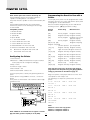
Mounting Panel
Select a dry location close to an unswitched AC source, a
ground connection and the telephone connection.
Remove printed circuit board, mounting hardware and
keypad from cardboard retainer inside panel. Before
attaching cabinet to wall, press the five white nylon
printed circuit board mounting studs and the ground
connection screw into cabinet from the back.
Pull all cables into cabinet and prepare them for
connection before mounting the circuit board to the back
of the cabinet. Press circuit board down onto mounting
studs.
Hook-up Procedure
DO NOT connect transformer or battery until all other
wiring has been connected. See power-up procedure.
Connect a ground cable from the cabinet ground
connection by the shortest and most direct route to a
grounding rod.
Connect zone cables to zone loop inputs and put end of
line resistors on any unused zones. Connect wires
supplying power for motion detectors to auxiliary supply.
Install keypads and connect wires to keypad terminals on
panel. Connect RJ31-X cord to telephone terminals. Do
not insert plug into RJ31-X jack.
Notice: Ensure that plugs and jacks meet the
dimension, tolerance and metallic plating requirements
of 47 C.F.R. Part 68, Subpart F.
Warning: FCC restricts using this equipment on certain
types of telephone lines. Read FCC Compliance
Statement at the end of this manual. Also, do not use
this equipment on a telephone line equipped with “call
holding” feature because the tone generated may
interfere with the communicator operation.
Connect bell or siren to “BELL [+]” and “BELL [-]”
terminals. Observe correct polarity for sirens and
polarized bells. Connect 1K ohm 1/2 watt resistor across
terminals to eliminate trouble condition if bell circuit is not
being used.
When the transformer is plugged in there should be
lights on the keypad and the buzzer connected to the
bell terminals may go on for a few seconds. The “Armed”
light may be on or off the first time the panel is powered.
The last armed/disarmed condition is stored in the
EEPROM memory so the panel will always power up in
the last armed/disarmed state. If the “Armed” light is on,
enter the default Master Code [1234] to disarm the
panel. If the keypad is not active, check for the presence
of AC power at the “AC” terminals, check the keypad
connections and check the panel fuses.
Terminal Connections
“AC” Power Terminals
Use a 16.5 VAC transformer with a minimum 40 VA rating
3