1
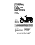
Owner's Manual
20.0 HP, 42" Mower
Electric Start
Automatic Transmission
Model No.
917.273481
I
[_
This product
a low emission
engine which
differently
fromhaspreviously
built engines.
Before operates
you start the
engine, read and understand this Owner's Manual.
IMPORTANT:
For answers to your questions
Read and follow all Safety
Rules and Instructions before
about this product, Call:
operating this equipment.
Sears Craftsman Help Line
5 am - 5 pm, Mon- Sat
1-800-659-5917
Sears, Roebuck and Co., Hoffman Estates,
Visit our Craftsman website:www.sears.com/craftsman
IL 60179 U.S.A
I
I
Warranty ................................................
2
Safety Rules ..........................................
3
Product Specifications ........................... 6
Assembly/P re-Operation ....................... 8
Operation .............................................
11
Maintenance .......................................
18
Maintenance Schedule ........................ 18
Service and Adjustments ..................... 22
Storage ................................................
29
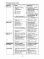
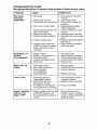
Troubleshooting ...................................
30
Repair Parts .........................................
34
Sears Service ........................ Back Cover
LIMITED WARRANTY ON CRAFTSMAN RIDING EQUIPMENT
For two (2) years from the date of purchase, if this Craftsman Riding Equipment is
maintained, lubricated and tuned up according to the instructions in the owner's manual,
Sears will repair or replace free of charge any parts that are found to be defective in
material or workmanship according to the guidelines of coverage listed below. Sears will
also provide free labor for these applicable warranted parts for the two full years. During
the first 30 days of purchase, there will be no charges to service the product at your
home for issues covered by this warranty. (See exclusions below). For your convenience, IN HOME warranty service will still be available after the first 30 days of purchase, but a trip charge will apply. This charge will be waived if the Craftsman product is
dropped off at an authorized Sears location. For the nearest authorized Sears location,
please call 1-800-4-MY-HOME®.
This warranty applies only while this product is within
the United States.
This Warranty does not cover:
• Expendable items which become worn during normal use, including but not limited to
blades, spark plugs, air cleaners, belts, and oil filters.
• Standard Maintenance Servicing, oil changes, or tune-ups.
• Tire replacement or repair caused by punctures from outside objects, such as nails,
thorns, stumps, or glass.
• Repairs necessary because of operator abuse, including but not limited to, damage
caused by towing objects beyond the capability of the riding equipment, impacting
objects that bend the frame or crankshaft, or over-speeding the engine.
• Repairs necessary because of operator negligence, including but not limited to, electrical and mechanical damage caused by improper storage, failure to use the proper
grade and amount of engine oil, failure to keep the deck clear of flammable debris,
or failure to maintain the equipment according to the instructions contained in the
owner's manual.
• Engine (fuel system) cleaning or repairs caused by fuel determined to be contaminated or oxidized (stale). In general, fuel should be used within 30 days of its purchase date.
• Normal deterioration and wear of the exterior finishes, or product label replacement.
• Riding equipment used for commercial or rental purposes.
LIMITED WARRANTY ON BATTERY
For ninety (90) days from date of purchase, if any battery included with this riding
equipment proves defective in material or workmanship and our testing determines the
battery will not hold a charge, Sears will replace the battery at no charge. During the
first 30 days of purchase, there will be no charges to replace the battery at your HOME.
After the first 30 days, for your convenience, IN-HOME warranty service will still be available but a trip charge will apply. This charge will be waived if the Craftsman product is
dropped off at an authorized Sears location. For the nearest authorized Sears location,
please call 1-800-4-MY-HOME®.
This battery warranty applies only while this product is within the United States.
This warranty gives you specific legal rights, and you may also have other rights, which
vary, from state to state.
Sears, Roebuck and Co.,Dept.817WA,
Hoffman Estates, IL 60179
2
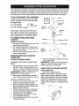
IMPORTANT: This cutting machine is capable of amputating hands and feet and throwing objects. Failure to observe the following safety instructions could result in serious
injury or death.
• Be aware of the mower discharge direction and do not point it at anyone. Do
not operate the mower without either
the entire grass catcher or the guard in
place.
• Slow down before turning.
• Never leave a running machine unattended. Always turn off blades, set
parking brake, stop engine, and remove
keys before dismounting.
• Turn off blades when not mowing.
• Stop engine before removing grass
catcher or unclogging chute.
• Mow only in daylight or good artificial
light.
• Do not operate the machine while under
the influence of alcohol or drugs.
• Watch for traffic when operating near or
crossing roadways.
• Use extra care when loading or unloading the machine into a trailer or
truck.
• Data indicates that operators, age 60
years and above, are involved in a large
percentage of riding mower-related injuries. These operators should evaluate
their ability to operate the riding mower
safely enough to protect themselves and
others from serious injury.
• Keep machine free of grass, leaves or
other debris build-up which can touch
hot exhaust / engine parts and burn. Do
not allow the mower deck to plow leaves
or other debris which can cause buildup to occur. Clean any oil or fuel
spillage before operating or storing the
machine. Allow machine to cool before
storage.
_WARNING:
In order to prevent accidental starting when setting up, transporting, adjusting or making repairs,
always disconnect spark plug wire and
place wire where it cannot contact spark
plug.
A(_WARNING: Do not coast down a hill in
neutral, you may lose control of the tractor.
_WARNING:
Tow only the attachments
that are recommended by and comply with
specifications of the manufacturer of your
tractor. Use common sense when towing.
Operate only at the lowest possible speed
when on a slope. Too heavy of a load,
while on a slope, is dangerous. Tires can
lose traction with the ground and cause
you to lose control of your tractor.
_;_WARNING: Engine exhaust, some of its
constituents, and certain vehicle components contain or emit chemicals known to
the State of California to cause cancer and
birth defects or other reproductive harm.
_WARNING:
Battery posts, terminals
and related accessories contain lead and
lead compounds, chemicals known to the
State of California to cause cancer and
birth defects or other reproductive harm.
Wash hands after handling.
I. GENERAL
OPERATION
• Read, understand, and follow all instructions in the manual and on the machine
before starting.
• Only allow responsible adults, who are
familiar with the instructions, to operate
the machine.
• Clear the area of objects such as rocks,
toys, wire, etc., which could be picked
up and thrown by the blade.
• Be sure the area is clear of other people
before mowing. Stop machine if anyone
enters the area.
• Never carry passengers.
• Do not mow in reverse unless absolutely necessary. Always look down and
behind before and while backing.
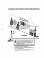
II. SLOPE OPERATION
Slopes are a major factor related to lossof-control and tipover accidents, which can
result in severe injury or death. All slopes
require extra caution. If you cannot back
up the slope or if you feel uneasy on it, do
not mow it.
3
DO:
• Mow up and down slopes, not across.
• Remove obstacles such as rocks, tree
limbs, etc.
• Watch for holes, ruts, or bumps. Uneven terrain could overturn the machine.
Tall grass can hide obstacles.
• Use slow speed. Choose a low gear
so that you will not have to stop or shift
while on the slope.
• Follow the manufacturer's recommendations for wheel weights or counterweights to improve stability.
• Use extra care with grass catchers or
other attachments. These can change
the stability of the machine.
• Keep all movement on the slopes slow
and gradual Do not make sudden
changes in speed or direction.
• Avoid starting or stopping on a slope.
If tires lose traction, disengage the
blades and proceed slowly straight
down the slope.
DO NOT:
• Never carry children. They may fall off
and be seriously injured or interfere with
safe machine operation.
• Never allow children to operate the
machine.
• Use extra care when approaching blind
corners, shrubs, trees, or other objects
that may obscure vision.
IV. SERVICE
• Use extra care in handling gasoline and
other fuels. They are flammable and
vapors are explosive.
- Use only an approved container.
- Never remove gas cap or add fuel
with the engine running. Allow
engine to cool before refueling. Do
not smoke.
- Never refuel the machine indoors.
- Never store the machine or fuel
container inside where there is an
open flame, such as a water heater.
• Never run a machine inside a closed
area.
• Keep nuts and bolts, especially blade
attachment bolts, tight and keep equipment in good condition.
• Never tamper with safety devices.
Check their proper operation regularly.
• Keep machine free of grass, leaves, or
other debris build-up. Clean oil or fuel
spillage. Allow machine to cool before
storing.
• Stop and inspect the equipment if you
strike an object. Repair, if necessary,
before restarting.
• Never make adjustments or repairs with
the engine running.
• Grass catcher components are subject
to wear, damage, and deterioration,
which could expose moving parts or
allow objects to be thrown. Frequently
check components and replace with
manufacturer's recommended parts,
when necessary.
• Mower blades are sharp and can cut.
Wrap the blade(s) or wear gloves, and
use extra caution when servicing them.
• Check brake operation frequently. Adjust and service as required.
• Do not turn on slopes unless necessary, and then, turn slowly and gradually
downhill, if possible.
• Do notmow near drop-offs, ditches,
or embankments. The mower could
suddenly turn over if a wheel is over
the edge of a cliff or ditch, or if an edge
caves in.
• Do not mow on wet grass. Reduced
traction could cause sliding.
• Do not try to stabilize the machine by
putting your foot on the ground.
• Do notuse grass catcher on steep
slopes.
III. CHILDREN
Tragic accidents can occur if the operator
is not alert to the presence of children.
Children are often attracted to the machine and the mowing activity. Neverassume that children will remain where you
last saw them.
• Keep children out of the mowing area
and under the watchful care of another
responsible adult.
• Be alert and turn machine off if children
enter the area.
• Before and when backing, look behind
and down for small children.
4
• Remove obstacles such as rocks, tree
limbs, etc.
• Watch for holes, ruts, or bumps. Uneven
terrain could overturn the machine. Tall
grass can hide obstacles.
• Use slow speed. Choose a low gear
so that you will not have to stop or shift
while on the slope.
• Avoid starting or stopping on a slope. If
tires lose traction, disengage the blades
and proceed slowly straight down the
slope.
• If machine stops while going uphill,
disengage blades, shift into reverse and
back down slowly.
• Do not turn on slopes unless necessary,
and then, turn slowly and gradually
downhill, if possible.
• Be sure the area is clear of other people
before mowing. Stop machine if anyone
enters the area.
• Never carry passengers or children
even with the blades off.
• Do not mow in reverse unless absolutely necessary. Always look down and
behind before and while backing.
• Never carry children. They may fall off
and be seriously injured or interfere with
safe machine operation.
• Keep children out of the mowing area
and under the watchful care of another
responsible adult.
• Be alert and turn machine off if children
enter the area.
• Before and when backing, look behind
and down for small children.
• Mow up and down slopes (15 ° Max), not
across.
5
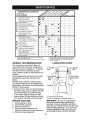
PRODUCT
In the state of California the above is required by law (Section 4442 of the California Public Resources Code). Other states
may have similar laws. Federal laws apply
on federal lands. A spark arrester for the
muffler is available through your nearest
Sears service center (See REPAIR PARTS
section of this manual).
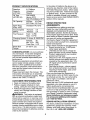
SPECIFICATIONS
Gasoline
Capacity
and Type:
Oil Type
API-SF-SJ):
4.0 Gallons
Unleaded
Regular
SAE10W30
(above 32°F)
SAE 5W-30(Below 32°F
Oil Capacity:
W/Filter:
4.0 Pints
W/O Filter: 3.5 Pints
Spark Plug:
(Gap: .030")
Ground Speed
(MPH):
Tire Pressure:
Champion
REPAIR PROTECTION
AGREEMENTS
Congratulations on making a smart purchase. Your new Craftsman@ product is
designed and manufactured for years of
dependable operation. But like all products,
it may require repair from time to time. That's
when having a Repair Protection Agreement
can save you money and aggravation.
Purchase a Repair Protection Agreement
now and protect yourself from unexpected
hassle and expense.
Here's what's included in the Agreement:
• Expert service by our 12,000 profesional repair specialists.
• Unlimited service and no charge for
parts and labor on all covered repairs.
• Product replacement if your covered
product can't be fixed.
• Discount of 10% from regular price of
service and service-related parts not
covered by the agreement; also, 10%
off regular price of preventive maintenance check.
• Fast help by phone- phone support
from a Sears technician on products
requiring in-home repair, plus convenient repair scheduling.
Once you purchase the Agreement, a
simple phone call is all that it takes for you
to schedule service. You can call anytime
day or night, or schedule a service appointment online.
Sears has over 12,000 professional repair
specialists, who have access to over 4.5
million quality parts and accessories.
That's the kind of professionalism you can
count on to help prolong the life of your
new purchase for years to come. Purchase
your Repair Protection Agreement today!
Some limitations
and exclusions
apply.
For prices and additional
information
call 1-800-827-6655.
RC12YC
Forward:
5.5
Reverse:
2.4
Front: 14 PSI
Rear: 10 PSI
Charging System:15 Amps @ 3600RPM
Battery:
Blade Bolt
Torque:
Amp/Hr:
35
Min. CCA:
280
Case Size: U1R
27-35 Ft. Lbs.
CONGRATULATIONS
on your purchase
of a new tractor. It has been designed,
engineered and manufactured to give
you the best possible dependability and
performance.
Should you experience any problem you
cannot easily remedy, please contact a
Sears or other qualified service center.
We have competent, well-trained technicians and the proper tools to service or
repair this tractor.
Please read and retain this manual. The
instructions will enable you to assemble
and maintain your tractor properly. Always
observe the "SAFETY RULES".
CUSTOMER
RESPONSIBILITIES
• Read and observe the safety rules.
• Follow a regular schedule in maintaining, caring for and using your tractor.
• Follow the instructions under"Maintenance" and "Storage" sections of this
owner's manual.
,_WARNING:
This tractor is equipped
with an internal combustion engine and
should not be used on or near any unimproved forest-covered, brush-covered or
grass-covered land unless the engine's
exhaust system is equipped with a spark
arrester meeting applicable local or state
laws (if any). If a spark arrester is used, it
should be maintained in effective working
order by the operator.
SEARS
INSTALLATION
SERVICE
For Sears professional installation of home
appliances, garage door openers, water
heaters, and other major home items, in
the U.S.A. call 1-800-4-MY-HOME®
6
Steering
Wheel
Extension
O
WheelSteering
//o
_\
Steering__._
Shaft
Insert
Steering _"_._J
Wheel_
Adapter
(1)
Flat Washer
ering
L__ll_!(1) H_!_18
eve
o
(1) kecknut
1/4-28
(1) kecknut
1/2-20
Seat
J
"_1
@
) Washer
17/32 x 1-3/16 x 12 Gauge
(1) Knob
i
I
_
_'("
_
(4) RetainerSprings
((_'_)
__.double
(4) Adjusting Bar_
Guage
_(4)
Video
"-t
loop,
Cassette
(4, Clevis Pins
_
Belt
]_]
Wheels
Wheels
(4) Shoulder
IO
@
(4) Washers
3/8 x 3/4 x 14 Ga.
Keys
(4) Lecknut
Slope Sheet
For Future Use
7
3/8-16
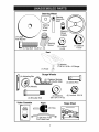
Your new tractor has been assembled at the factory with the exception of those parts left
unassembled for shipping purposes. To ensure safe and proper operation of your tractor
all parts and hardware you assemble must be tightened securely. Use the correct tools
as necessary to insure proper tightness. Review the video cassette before you begin.
TOOLS REQUIRED
FOR ASSEMBLY
A socket wrench set will make assembly
easier. Standard wrench sizes you need
are listed below.
(1) 3/4"wrench
(1) Pliers
(2) 7/16" wrench
(1) Utility knife
(1) Tire pressure gauge
When right or left hand is mentioned in
this manual, it means, from your point of
view, when you are in the operating position (seated behind the steering wheel).
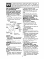
TO REMOVE TRACTOR
FROM
CARTON
UNPACK CARTON
1. Remove all accessible loose parts and
parts boxes from carton.
2. Cut along dotted lines on all four panels of carton. Remove end panels and
lay side panels flat.
3. Check for any additional loose parts or
cartons and remove.
Adapte
Shaft
1/4 Locknut
;x Bolt
Lower
Steering
Shaft
BEFORE
REMOVING TRACTOR
FROM SKID
ATTACH STEERING WHEEL
\
,
"-_"
8. Remove protective materials from tractor hood and grill.
IMPORTANT: Check for and remove any
staples in skid that may )uncture tires
where tractor is to roll off skid.
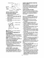
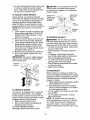
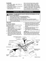
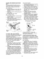
ASSEMBLE EXTENSION SHAFT AND
BOOT
1. Slide extension shaft onto lower steering shaft. Align mounting holes in extension and lower shafts and install 1/4
hex bolt and Iocknut. Tighten securely.
IMPORTANT: Tighten bolt and nut securely to 10-12 ft. Ibs torque.
2. Place tabs of steering boot over tab
slots in dash and push down to secure.
INSTALL STEERING WHEEL
3. Position front wheels of the tractor so
they are pointing straight forward.
4. Remove steering wheel adapter from
steering wheel and slide adapter onto
steering shaft extension.
5. Position steering wheel so cross bars
are horizontal (left to right) and slide
inside boot and onto adapter.
6. Assemble large flat washer, 1/2 hex
nut and tighten securely.
7. Snap steering wheel insert into center
of steering wheel.
HOWTO SET UP YOUR TRACTOR
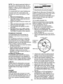
CHECK BATTERY
1. Lift hood to raised position.
NOTE: If this battery is put into service
after month and year indicated on label
(label located between terminals) charge
battery for minimum of one hour at 6-10
amps. (See "BATTERY" in Maintenance
section of this manual for charging instructions).
Label
/
_2
8
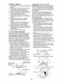
INSTALL SEAT
3. Place freewheel control in disengaged
position to disengage transmission
(See "TO TRANSPORT" in the Operation section of this manual).
4. Roll tractor forward off skid.
5. Remove banding holding the deflector
shield up against tractor.
Adjust seat before tightening adjustment
knob.
1. Remove adjustment knob and flat
washer securing seat to cardboard
packing and set aside for assembly of
seat to tractor.
2. Pivot seat upward and remove from
the cardboard packing. Remove the
cardboard packing and discard.
3. Place seat on seat pan so head of
shoulder bolts are positioned over the
large slotted holes in pan.
4. Push down on seat to engage shoulder bolts in slots and pull seat towards
rear of tractor.
5. Pivot seat and pan forward and assemble adjustment knob and flat
washer loosely. Do not tighten.
6. Lower seat into operating position and
sit in seat.
7. Slide seat until a comfortable position
is reached which allows you to press
clutch/brake pedal all the way down.
8. Get off seat without moving its adjusted position.
9. Raise seat and tighten adjustment
knob securely.
TO DRIVE TRACTOR
OFF SKID (See
Operation
section for location and
function of controls)
_WARNING:
Before starting, read, understand and follow all instructions in the
Operation section of this manual. Be sure
tractor is in a well-ventilated area. Be sure
the area in front of tractor is clear of other
people and objects.
1. Be sure all the above assembly steps
have been completed.
2. Check engine oil level and fill fuel tank
with gasoline.
3. Place freewheel control in "transmission engaged" position (see "TO
TRANSPORT" in Operation section of
this manual).
4. Sit on seat in operating position, depress brake pedal and set the parking
brake.
5. Press lift lever plunger and raise
attachment lift lever to its highest position.
6. Start the engine. After engine has
started, move throttle control to idle
position.
7. Release parking brake.
8. Slowly depress forward drive pedal and
drive tractor off skid.
9. Apply brake to stop tractor and set
parking brake.
10.Turn ignition key to "STOP" position.
Continue with the instructions that follow.
Seat
Seat Pan
Shoulder Bolts
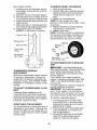
ASSEMBLE GAUGE WHEELS TO
MOWER DECK
The gauge wheels are designed to keep
the mower deck in proper position when
operating mower. Be sure they are properly adjusted to ensure optimum mower
performance.
1. Slide gauge wheel bar down into
bracket channel, Be sure that gauge
wheel bar aligning holes are on top. Assemble gauge wheels as shown using
shoulder bolts, 3/8 washers and 3/8-16
center Iocknuts and tighten securely.
2. Adjust gauge wheels before operating mower. See "TO ADJUST GAUGE
WHEELS" in the Operation section of
this manual.
Adjustment Knob'
NOTE: You may now roll or drive your
tractor off the skid. Follow the appropriate
instruction below to remove the tractor
from the skid.
TO ROLL TRACTOR
OFF SKID (See
Operation
section for location and
function of controls)
1. Press lift lever plunger and raise
attachment lift lever to its highest position.
2. Release parking brake by depressing
brake pedal.
9
CHECK FOR PROPER POSITION
OF ALL BELTS
See the figures that are shown for replacing motion and mower blade drive belts
in the Service and Adjustments section
of this manual. Verify that the belts are
routed correctly.
Pin
CHECK
INSTALL MULCHER
PLATE
(If previously
removed)
1. Raise and hold deflector shield in
upright position.
2. Place front of mulcher plate over front
of mower deck opening and slide into
place, as shown.
3. Hook front latch into hole on front of
mower deck.
4. Hook rear latch into hole on back of
mower deck.
Plate
AI_CAUTION: Do not remove deflector
shield from mower.
TO CONVERTTO
BAGGING OR
DISCHARGING
Simply remove mulcher plate and store in
a safe place. Your mower is now ready for
discharging or installation of optional grass
catcher accessory.
NOTE: It is not necessary to change
blades. The mulching blades are designed
for discharging and bagging also.
CHECKTIRE
PRESSURE
The tires on your tractor were overinflated
at the factory for shipping purposes. Correct tire pressure is important for best
cutting performance.
• Reduce tire pressure to PSI shown in
"PRODUCT SPECIFICATIONS" section
of this manual.
CHECK DECK LEVELNESS
For best cutting results, mower housing should be properly leveled. See "TO
LEVEL MOWER HOUSING" in the Service
and Adjustments section of this manual.
BRAKE
SYSTEM
After you learn how to operate your tractor, check to see that the brake is properly
adjusted. See "TO ADJUST BRAKE" in
the Service and Adjustments section of
this manual.
v"CHECKLIST
Before you operate your new tractor, we
wish to assure that you receive the best
performance and satisfaction from this
quality product.
Please review the following checklist:
•/ All assembly instructions have been
completed.
•/ No remaining loose parts in carton.
•/ Battery is properly prepared and
charged.
(Minimum 1 hour at 6 amps).
•/ Seat is adjusted comfortably and tightened securely.
•/ All tires are properly inflated. (For shipping purposes, the tires were overinflated at the factory).
•/ Be sure mower deck is properly leveled
side-to-side/front-to-rear
for best cutting
results. (Tires must be properly inflated
for leveling).
•/ Check mower and drive belts. Be sure
they are routed properly around pulleys
and inside all belt keepers.
•/ Check wiring. See that all connections
are still secure and wires are properly
clamped.
•/ Before driving tractor, be sure freewheel
control is in '"transmission engaged"
position (see "TO TRANSPORT" in the
Operation section of this manual).
While learning how to use your tractor, pay
extra attention to the following important
items:
•/ Engine oil is at proper level.
•/ Fuel tank is filled with fresh, clean, regular unleaded gasoline.
•/ Become familiar with all controls - their
location and function. Operate them
before you start the engine.
•/ Be sure brake system is in safe operating condition.
•/ It is important to purge the transmission
before operating your tractor for the first
time. Follow.proper starting and transmission purging instructions (See "TO
START ENGINE" and "PURGE TRANSMISSION" in the Operation section of
10 this manual).
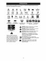
These symbols mayappear on your tractor or in literaturesupplied with the product.
Learn and understandtheir meaning.
R
REVERSE
ENGINE OFF
N
H
L
NEUTRAL
HIGH
LOW
LIGHTS ON
OVER TEMP
LIGHT
FUEL
ENGINE ON
OIL PRESSURE
I'-,I
CHOKE
ENGINE START
BATTERY
FAST
PARKING
REVERSE
BRAKE
FORWARD
SLOW
PARKING BRAKE
LOCKED
MOWER
HEIGHT
IGNITION
PARKING BRAKE
UNLOCKED
MOWER
LIFT
@@@@@
ATTACHMENT
CLUTCH ENGAGED
ATTACHMENT
CLUTCH DISENGAGED
FREE WHEEL
(Automatic
Models only)
&
Failure to follow instructions
could result in serious injury or
death. The safety alert symbol
is used to identify safety information about hazards which can
result in death, serious injury
and/or property damage.
DANGER, KEEP HANDS
AND FEET AWAY
&
&
&
KEEP AREA CLEAR
(SEE SAFETY
SLOPE HAZARDS
RULES SECTION)
DANGER indicates a hazard which, if not avoided,
will result in death or serious injury.
WARNING indicates a hazard which, if not avoided,
could result in death or serious injury.
CAUTION indicates a hazard which, if not avoided,
might result in minor or moderate injury.
CAUTION when used without the alert symbol,
indicates a situation that could result in damage
to the tractor and/or engine.
_HOT
SURFACES indicates a hazard which,
._,.
if not avoided, could result in death, serious injury
"'"
and/or property damage.
FIRE indicates a hazard which, if not avoided,
could result in death, serious injury and/or
property damage.
11
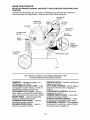
KNOW YOUR TRACTOR
READ THIS OWNER'S MANUAL AND SAFETY RULES BEFORE OPERATING YOUR
TRACTOR
Compare the illustrations with your tractor to familiarize yourself with the locations of
various controls and adjustments. Save this manual for future reference.
Light Switch
Position
Attachment
Clutch Lever
Ignition
Switch
Lift Lever
Plunger
Attachment
Throttle/Choke
Control
Reverse
B_ke
Pedal
Height
ustment
Indicator
FreeWheel
Control
Parking Brake Lever
02730
Our tractors conform to the safety standards of the
American National Standards Institute.
IGNITION SWITCH - Used for starting and
stopping the engine.
LIFT LEVER PLUNGER - Used to release
attachment lift lever when changing its
position.
LIGHT SWITCH POSITION -Turns the
headlights on and off.
PARKING BRAKE LEVER - Locks brake
pedal into the brake position.
THROTTLE/CHOKE
CONTROL - Used
for starting and controling engine speed.
FREEWHEEL CONTROL - Disengagages
transmission for pushing or slowly towing
the tractor with the engine off.
AMMETER - Indicates charging (+) or
discharging (-) of battery.
ATTACHMENT CLUTCH LEVER - Used
to engage the mower blades, or other attachments mounted to your tractor.
ATTACHMENT LIFT LEVER - Used to
raise, lower, and adjust the mower deck or
other attachments mounted to your tractor.
BRAKE PEDAL - Used for braking the
tractor and starting the engine.
FORWARD DRIVE PEDAL - Used for
forward movement of tractor.
REVERSE DRIVE PEDAL - Used for
reverse movement of tractor.
12
The operation of any tractor can result in foreign objects thrown into the
eyes, which can result in severe eye damage. Always wear safety glasses
or eye shields while operating your tractor or performing any adjustments
or repairs. We recommend standard safety glasses or a wide vision safety
mask worn over spectacles.
HOWTO
USE YOUR TRACTOR
• Never use choke to stop engine.
IMPORTANT: Leaving the ignition switch
in any position other than "STOP" will
cause the battery to discharge and go
dead.
NOTE: Under certain conditions when
tractor is standing idle with the engine
running, hot engine exhaust gases may
cause "browning" of grass. To eliminate
this possibility, always stop engine when
stopping tractor on grass areas.
_CAUTION.Always stop tractor completely, as described above, before leaving
the operator's position.
TO SET PARKING BRAKE
Your tractor is equipped with an operator
presence sensing switch. When engine
is running, any attempt by the operator
to leave the seat without first setting the
parking brake will shut off the engine.
1. Depress brake pedal all the way down
and hold.
2. Pull parking brake lever up and release
pressure from brake pedal. Pedal
should remain in brake position. Make
sure parking brake will hold tractor
secu re.
Attachment Clutch Lever
Position
Ignition
Throttle/Choke
Control
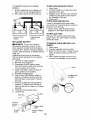
TO USE THROTTLE
Always operate engine at full throttle.
• Operating engine at less than full
throttle reduces the battery charging
rate.
• Full throttle offers the best bagging and
mower performance.
"Disengaged"
Drive Pedal
B_ke
Pedal
TO MOVE FORWARD AND
BACKWARD
Reverse
Drive
Pedal
The direction and speed of movement is
controlled by the forward and reverse drive
pedals.
1. Start tractor and release parking brake.
2. Slowly depress forward or reverse
drive pedal to begin movement.
Ground speed increases the further
down the pedal is depressed.
"Disengaged"
Position
"Brake"
Position
pz
g Brake
"Engaged"Position
STOPPING
MOWER
BLADES
-
• To stop mower blades, push attachment
clutch switch in to disengaged position.
GROUND
DRIVE
CONTROL
TO ADJUST
-
MOWER
CUTTING
HEIGHT
The position of the attachment lift lever
determines the cutting height.
• Grasp lift lever.
• Press plunger with thumb and move
lever to desired position.
The cutting height range is approximately 1-1/2 to 4". The heights are measured from the ground to the blade tip with
the engine not running. These heights
are approximate and may vary depending
upon soil conditions, height of grass and
types of grass being mowed.
• The average lawn should be cut to approximately 2-1/2 inches during the cool
season and to over 3 inches during hot
months. For healthier and better looking
lawns, mow often and after moderate
growth.
• To stop ground drive, depress brake
pedal all the way down.
IMPORTANT: Forward and reverse drive
pedals return to neutral position when not
depressed.
ENGINE • Move throttle control between half and
full speed (fast) position.
NOTE: Failure to move throttle control
between half and full speed (fast) position, before stopping, may cause engine to
"backfire".
• Turn ignition key to "STOP" position and
remove key. Always remove key when
leaving tractor to prevent unauthorized
use.
13
• For best cutting performance,
grass over
6 inches in height should be mowed
twice. Make the first cut relatively high;
the second to desired height.
A(_CAUTION: Do not operate the mower
without either the entire grass catcher,
on mowers so equipped, or the deflector
shield in place.
TO ADJUST GAUGE WHEELS
Attachment
Gauge wheels are properly adjusted
when they are slightly off the ground when
mower is at the desired cutting height in
operating position. Gauge wheels then
keep the deck in proper position to help
prevent scalping in most terrain conditions.
NOTE: Be sure tractor is on a flat level
surface.
1. Lower mower and adjust mower to desired cutting height(See "TO ADJUST
MOWER CUTTING HEIGHT' in this
section of manual).
2. Remove retainer spring and clevis pin
which secure each gauge wheel bar.
3. Lower gauge wheels to ground. Raise
gauge wheels slightly to align holes
in bracket and gauge wheel bar and
insert clevis pin. Gauge wheels should
be slightly off the ground.
4. Replace retainer spring into clevis pin.
5. Be sure all gauge wheels are in the
same setting.
IMPORTANT: Be sure to readjust gauge
wheels if you change the cutting height
of the mower deck.
"Engaged"
Position
Attachemnt
Lever
f,;,
High
Position
Position
"Disengaged'_
Position
Deflector
TO OPERATE ON HILLS
_WARNING:
Do not drive up or down
hills with slopes greater than 15° and do
not drive across any slope. Use the slope
guide provided at the back of this manual.
• Choose the slowest speed before starting up or down hills.
• Avoid stopping or changing speed on
hills.
• If stopping is absolutely necessary,
push brake pedal quickly to brake position and engage parking brake.
• To restart movement, slowly release
parking brake and brake pedal.
• Slowly depress appropriate drive pedal
to slowest setting.
• Make all turns slowly.
Retainer
Spring
TO TRANSPORT
When pushing or towing your tractor, be
sure to disengage transmission by placing
freewheel control in freewheeling position.
Freewheel control is located at the rear
drawbar of tractor.
1. Raise attachment lift to highest position
with attachment lift control.
2. Pull freewheel control out and down
into the slot and release so it is held in
the disengaged position.
• Do not push or tow tractor at more than
two (2) MPH.
• To re-engage transmission, reverse
above procedure.
NOTE: To protect hood from damage
when transporting your tractor on a truck
or a trailer, be sure hood is closed and
secured to tractor. Use an appropriate
means of tying hood to tractor (rope, cord,
etc.).
Clevis
Pin
TO OPERATE
MOWER
Your tractor is equipped with an operator
presence sensing switch. Any attempt
by the operator to leave the seat with the
engine running and the attachment clutch
engaged will shut off the engine.
1. Select desired height of cut.
2. Start mower blades by engaging attachment clutch control.
TO STOP MOWER BLADES disengage attachment clutch control.
14
Transmission
Transmission
Engaged
_CAUTION:
Wipe off any spilled oil or
fuel. Do not store, spill or use gasoline
near an open flame.
IMPORTANT: When operating in temperatures below 32°F(0°C), use fresh, clean
winter grade gasoline to help insure good
cold weather starting.
CAUTION: Alcohol blended fuels (called
gasohol or using ethanol or methanol) can
attract moisture which leads to separation and formation of acids during storage.
Acidic gas can damage the fuel system of
an engine while in storage.
To avoid engine problems, the fuel system
should be emptied before storage of 30
days or longer. Drain the gas tank, start
the engine and let it run until the fuel lines
and carburetor are empty. Use fresh fuel
next season. See Storage Instructions for
additional information.
Never use engine or carburetor cleaner
products in the fuel tank or permanent
damage may occur.
Disengaged
TOWING CARTS AND OTHER ATTACHMENTS
Tow only the attachments that are recommended by and comply with specifications
of the manufacturer of your tractor. Use
common sense when towing. Too heavy
of a load, while on a slope, is dangerous.
Tires can lose traction with the ground and
cause you to lose control of your tractor.
BEFORE
STARTING THE ENGINE
TO START ENGINE
When starting the engine for the first time
or if the engine has run out of fuel, it will
take extra cranking time to move fuel from
the tank to the engine.
1. Be sure freewheel control is in the
transmission engaged position.
2. Sit on seat in operating position,
depress brake pedal and set parking
brake.
3. Move attachment clutch to disengaged
position.
4. Move throttle control to choke position.
NOTE: Before starting, read the warm
and cold starting procedures below.
5. Insert key into ignition and turn key
clockwise to start position and release
key as soon as engine starts. Do not
run starter continuously for more than
fifteen seconds per minute.
If the engine does not start after several attempts, move throttle control to
fast position, wait a few minutes and
try again. If engine still does not start,
move the throttle control back to the
choke position and retry.
CHECK ENGINE OIL LEVEL
The engine in your tractor has been
shipped, from the factory, already filled
with summer weight oil.
1. Check engine oil with tractor on level
ground.
2. Unthread and remove oil fill cap/
dipstick; wipe oil off. Reinsert the
dipstick into the tube and rest oil fill
cap on the tube. Do not thread the cap
onto the tube. Remove and read oil
level. If necessary, add oil until "FULL'
mark on dipstick is reached. Do not
overfill.
• For cold weather operation you should
change oil for easier starting (See the
oil viscosity chart in the Maintenance
section of this manual).
• To change engine oil, see the Maintenance section in this manual.
ADD GASOLINE
• Fill fuel tank to bottom of tank filler neck.
Do not overfill. Use fresh, clean, regular
unleaded gasoline with a minimum of 87
octane. (Use of leaded gasoline will increase carbon and lead oxide deposits
and reduce valve life). Do not mix oil
with gasoline. Purchase fuel in quantities that can be used within 30 days to
assure fuel freshness.
WARM WEATHER STARTING (50 ° F and
above)
6. When engine starts, move the throttle
control to the fast position.
• The attachments and ground drive can
now be used. If the engine does not
accept the load, restart the engine and
allow it to warm up for one minute using
the choke as described above.
15
COLD WEATHER STARTING ( 50° F and
below)
6. When engine starts, leave throttle
control in choke position until engine
warms up and begins to run roughly.
Once rough running begins, immediately move the throttle control to the
fast position. Engine warm-up may
take from several seconds to several
minutes (the colder the temperature,
the longer the warm-up).
AUTOMATIC TRANSMISSION WARM UP
3. Sitting in the tractor seat, start engine.
After the engine is running, move
throttle control to slow position. Disengage parking brake.
4. Depress forward drive pedal to full
forward position and hold for five (5)
seconds and release pedal. Depress
reverse drive pedal to full reverse position and hold for five (5) seconds and
release pedal. Repeat this procedure
three (3) times.
NOTE: During this step there will be no
movement of drive wheels. The air is being
removed from hydraulic drive system.
5. Shutoff engine and set parking brake.
6. Engage transmission by placing freewheel control in engaged position (See
"TO TRANSPORT" in this section of
manual).
7. Sitting in the tractor seat, start engine.
After the engine is running, move
throttle control to half (1/2) speed.
Disengage parking brake.
8. Drive tractor forward for approximately
five feet then backwards for five feet.
Repeat this driving procedure three
times.
Your transmission is now purged and now
ready for normal operation.
Before driving the unit in cold weather,
the transmission should be warmed up as
follows:
1. Be sure the tractor is on level ground.
2. Release the parking brake and let
the brake slowly return to operating
position.
3. Allow one minute for transmission to
warm up. This can be done during
the engine warm up period.
• The attachments can also be used during the engine warm-up period after the
transmission has been warmed up.
NOTE: If at a high altitude (above 3000
feet) or in cold temperatures (below 32 F)
the carburetor fuel mixture may need to
be adjusted for best engine performance
(see "TO ADJUST CARBURETOR" in the
Service and Adjustments section of this
manual).
PURGE
MOWING TIPS
• Mower should be properly leveled for
best mowing performance. See "TO
LEVEL MOWER HOUSING" in the
Service and Adjustments section of this
manual.
• The left hand side of mower should be
used for trimming.
• Drive so that clippings are discharged
onto the area that has already been cut.
Have the cut area to the right of the tractor. This will result in a more even distribution of clippings and more uniform
cutting.
• When mowing large areas, start by
turning to the right so that clippings will
discharge away from shrubs, fences,
driveways, etc. After one or two rounds,
mow in the opposite direction making
left hand turns until finished.
TRANSMISSION
_CAUTION:
Never engage or disengage freewheel lever while the engine
is running.
To ensure proper operation and performance, it is recommended that the
transmission be purged before operating
tractor for the first time. This procedure will
remove any trapped air inside the transmission which may have developed during
shipping of your tractor.
IMPORTANT: Should your transmission
require removal for service or replacement, it should be purged after reinstallation before operating the tractor.
1. Place tractor safely on level surface
with engine off and parking brake set.
2. Disengage transmission by placing
freewheel control in disengaged position (See "TO TRANSPORT' in this
section of manual).
16
00272
• If grass is extremely tall, it should be
mowed twice to reduce load and possible fire hazard from dried clippings.
Make first cut relatively high; the second
to the desired height.
• Do not mow grass when it is wet.
Wet grass will plug mower and leave
undesirable clumps. Allow grass to dry
before mowing.
• Always operate engine at full throttle
when mowing to assure better mowing performance and proper discharge
of material. Regulate ground speed by
selecting a low enough gear to give the
mower cutting performance as well as
the quality of cut desired.
• When operating attachments, select a
ground speed that will suit the terrain
and give best performance of the attachment being used.
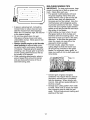
MULCHING
MOWING TIPS
IMPORTANT: For best performance, keep
mower housing free of built-up grass and
trash. Clean after each use.
• The special mulching blade will recut
the grass clippings many times and
reduce them in size so that as they fall
onto the lawn they will disperse into
the grass and not be noticed. Also, the
mulched grass will biodegrade quickly
to provide nutrients for the lawn. Always
mulch with your highest engine (blade)
speed as this will provide the best recutting action of the blades.
• Avoid cutting your lawn when it is wet.
Wet grass tends to form clumps and
interferes with the mulching action. The
best time to mow your lawn is the early
afternoon. At this time the grass has
dried, the newly cut area will not be
exposed to direct sunlight.
• For best results, adjust the mower
cutting height so that the mower cuts
off only the top one-third of the grass
blades. For extremely heavy grass, reduce your width of cut on each pass and
mow slowly.
Max 1/3
• Certain types of grass and grass
conditions may require that an area be
mu_ched a second time to completely
hide the clippings. When doing a second cut, mow across (perpendicular) to
the first cut path.
• Change your cutting pattern from week
to week. Mow north to south one week
then change to east to west the next
week. This will help prevent matting and
graining of the lawn.
17
ASEGU
YOU
R
LARCOMPLETE
SERVICE
T
R
/___RVlCE_)_._
Check Operator Presence
Interlock Systems
Lubrication
0
Sharpen/Replace
Check
Battery Level
Mower
R
Clean
Battery
Check
V_Belts
Check
Engine
_
Ks
i3
Cooling
I_
Oil Level
II_
Oil (with oil filter)
E
Change
Engine
Oil (without
N
G
CleanAirFiiter
Clean Air Screen
_
Inspect
E
Replace
MuffledSpark
I1_,_
oil filter)
I_
_,2
_/# _
Attester
I_
Oil Filter (If equipped)
Cooling
I_
Fins
_
Replace
Spark
Plug
Replace
Air Filter Paper Cartridge
Replace
Fuel Filter
1 = Change
more often when operating
in high ambient
temperatures.
2 = Service
more often when operating
I_
under
in dirty
I1_
11_2
a heavy
or dusty
load or
3 - Replace
blades more often when mowing
in sandy soil.
4 _ Not required
if equipped
with maintenancertree
battery.
conditions.
5 _ Tighten front axle pivot
Do not overtighten.
RECOMMENDATIONS
bolt to 35 tt.dbs,
LUBRICATION
The warranty on this tractor does not
cover items that have been subjected to
operator abuse or negligence. To receive
full value from the warranty, operator
must maintain tractor as instructed in this
manual.
Some adjustments will need to be made
periodically to properly maintain your
tractor.
At least once a season, check to see if
you should make any of the adjustments
described in the Service and Adjustments
section of this manual.
• At least once a year you should replace
the spark plug, clean or replace air filter,
and check blades and belts for wear.
A new spark plug and clean air filter
assure proper air-fuel mixture and help
your engine run better and last longer.
BEFORE
I1_
and Terminals
Engine
Engine
DATES
I1_
Blades
Change
GENERAL
_.4,_ q4._ _._
Chart
Check Transaxle
Clean
£,4,q; q4.e
and
Check for Loose Fasteners
T
_4_
(9 Spindle-Zerk
CHART
to_-,
i_--'
_ SePi_dle
_Front Wheel :-' /
Bearing _,_
:======,
",'.)
Zerk
maximum.
j .= _Front Wheel
/ ,_earing
Zerk
i
_,j_
_Engine'..-_-,
'
i
I
i
i
I
I
i
I
I
• ....
i!
(_ General Purpose Grease
Refer to Maintenance "ENGINE" Section
EACH USE
IMPORTANT: Do not oil or grease the
pivot points which have special nylon
bearings. Viscous lubricants will attract
dust and dirt that will shorten the life of the
self-lubricating bearings. If you feel they
must be lubricated, use only a dry, powdered graphite type lubricant sparingly.
1.
2.
3.
4.
Check engine oil level.
Check brake operation.
Check tire pressure.
Check operator presence and
interlock systems for proper operation.
5. Check for loose fasteners.
18
TRACTOR
4. Reassemble blade bolt, lock washer
and flat washer in exact order as
shown.
5. Tighten blade bolt securely (27-35 Ft.
Lbs. torque).
IMPORTANT:
Blade bolt is heat treated.
If bolt needs replacing, replace only with
approve bolt shown in the Repair Parts.
Always observe safety rules when performing any maintenance.
BRAKE OPERATION
If tractor requires more than six (6) feet
stopping distance at high speed in highest
gear, then brake must be adjusted. (See
"TO ADJUST BRAKE" in the Service and
Adjustments section of this manual).
TIRES
• Maintain proper air pressure in all tires
(See "PRODUCT SPECIFICATIONS"
section of this manual).
• Keep tires free of gasoline, oil, or insect
control chemicals which can harm rubber.
• Avoid stumps, stones, deep ruts, sharp
objects and other hazards that may
cause tire damage.
NOTE: To seal tire punctures and prevent
flat tires due to slow leaks, tire sealant
may be purchased from your local parts
dealer. Tire sealant also prevents tire dry
rot and corrosion.
OPERATOR PRESENCE SYSTEM
Be sure operator presence and interlock
systems are working properly. If your tractor does not function as described, repair
the problem immediately.
• The engine should not start unless
the brake pedal is fully depressed and
attachement clutch control is in the
disengaged position.
• When the engine is running, any attempt by the operator to leave the seat
without first setting the parking brake
should shut off the engine.
• When the engine is running and the
attachment clutch is engaged, any attempt by the operator to leave the seat
should shut off the engine.
• The attachment clutch should never operate unless the operator is in the seat.
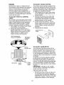
BLADE CARE
For best results mower blades must be
kept sharp. Replace bent or damaged
blades.
Flat
Washer\
Edge Up
Lock
WashersBlade Bolt
Mandrel
_Star
TO SHARPEN BLADE
NOTE: We do not recommend sharpening blade - but if you do, be sure the
blade is balanced.
Care should be taken to keep the blade
balanced. An unbalanced blade will cause
excessive vibration and eventual damage
to mower and engine.
• The blade can be sharpened with a file
or on a grinding wheel. Do not attempt
to sharpen while on the mower.
• To check blade balance, you will need a
5/8" diameter steel bolt, pin, or a cone
balancer. (When using a cone balancer,
follow the instructions supplied with
balancer.)
NOTE: Do not use a nail for balancing
blade. The lobes of the center hole may
appear to be centered, but are not.
• Slide blade on to an unthreaded portion
of the steel bolt or pin and hold the
bolt or pin parallel with the ground. If
blade is balanced, it should remain in a
horizontal position. If either end of the
blade moves downward, sharpen the
heavy end until the blade is balanced.
Blade
5/8" Bolt or
Center
BATTERY
BLADE REMOVAL
1. Raise mower to highest position to allow access to blades.
2. Remove blade bolt, lock washer and
flat washer securing blade.
3. Install new or resharpened blade
with trailing edge up towards deck as
shown.
IMPORTANT: To ensure proper assembly,
center hole in blade must align with star
on mandrel assembly.
Your tractor has a battery charging system
which is sufficient for normal use. However, periodic charging of the battery
with an automotive charger will extend
its life.
• Keep battery and terminals clean.
• Keep battery bolts tight.
• Keep small vent holes open.
• Recharge at 6-10 amperes for 1 hour.
19
NOTE: The original equipment battery on
your tractor is maintenance free. Do not
attempt to open or remove caps or covers.
Adding or checking level of electrolyte is
not necessary.
TO CLEAN BATTERY AND TERMINALS
Change the oil after every 50 hours of operation or at least once a year if the tractor
is not used for 50 hours in one year.
Check the crankcase oil level before starting the engine and after each eight (8)
hours of operation.
Corrosion and dirt on the battery and
terminals can cause the battery to "leak"
power.
1. Remove terminal guard.
2. Disconnect BLACK battery cable first
then RED battery cable and remove
battery from tractor.
3. Rinse the battery with plain water and
dry.
4. Clean terminals and battery cable ends
with wire brush until bright.
5. Coat terminals with grease or petroleum jelly.
6. Reinstall battery (See "REPLACING
BATTERY" in the SERVICE AND ADJUSTMENTS section of this manual).
TO CHANGE ENGINE OIL
Determine temperature range expected
before oil change. All oil must meet API
service classification SF-SJ.
• Be sure tractor is on level surface.
• Oil will drain more freely when warm.
• Catch oil in a suitable container.
1. Remove oil fill cap/dipstick. Be careful
not to allow dirt to enter the engine
when changing oil.
2. Remove yellow cap from end of drain
valve and install the drain tube onto the
fitting.
Oil Drain Valve
TRANSAXLE COOLING
The transmission fan and cooling fins
should be kept clean to assure proper
cooling.
Do not attempt to clean fan or transmission while engine is running or while the
transmission is hot. To prevent possible
damage to seals, do not use high pressure
water or steam to clean transaxle.
• Inspect cooling fan to be sure fan blades
are intact and clean.
• Inspect cooling fins for dirt, grass clippings and other materials. To prevent
damage to seals, do not use compressed air or high pressure sprayer to
clean cooling fins.
TRANSAXLE PUMP FLUID
The transaxle was sealed at the factory
and fluid maintenance is not required for
the life of the transaxle. Should the transaxle ever leak or require servicing, contact
a Sears or other qualified service center.
Closed and
,__
Locked l 'J
Pos,t,on
I
L'"'" \
Yellow Cap _/!--"_'"X_q'_
"
'_
_._/"
_"
"Drain
Tube
O2463
V-BELTS
Check V-belts for deterioration and wear
after 100 hours of operation and replace
if necessary. The belts are not adjustable.
Replace belts if they begin to slip from
wear.
ENGINE
LUBRICATION
Only use high quality detergent oil rated
with API service classification SF-SJ. Select the oil's SAE viscosity grade according to your expected operating temperature.
20
3. Unlock drain valve by pushing inward
slightly and turning counterclockwise.
4. To open, pull out on the drain valve.
5. After oil has drained completely, close
and lock the drain valve by pushing
inward and turning clockwise until the
pin is in the locked position as shown.
6. Remove the drain tube and replace the
cap onto the end of the drain valve.
7. Refill engine with oil through oil fill dipstick tube. Pour slowly. Do not overfill.
For approximate capacity see "PRODUCT SPECIFICATIONS" section of this
manual.
8. Use gauge on oil fill cap/dipstick for
checking level. Insert dipstick into
the tube and rest the oil fill cap on the
tube. Do not thread the cap onto the
tube when taking reading.
Keep oil
at "FULl" line on dipstick. Tighten cap
onto the tube securely when finished.
ENGINE
OIL FILTER
CLEAN
Replace the engine oil filter every season
or every other oil change if the tractor is
used more than 100 hours in one year.
AIR FILTER
AREAS
To insure proper cooling, make sure the
grass screen, cooling fins, and other external surfaces of the engine are kept clean
at all times.
Every 100 hours of operation (more often
under extremely dusty, dirty conditions),
remove the blower housing and other cooling shrouds. Clean the cooling fins and
external surfaces as necessary. Make sure
the cooling shrouds are reinstalled.
NOTE:
Operating the engine with a
blocked grass screen, dirty or plugged
cooling fins, and/or cooling shrouds
removed will cause engine damage due to
overheating.
Your engine will not run properly using a
dirty air filter. Clean the foam pre-cleaner
after every 25 hours of operation or every
season. Service paper cartridge every
100 hours of operation or every season,
whichever occurs first.
Service air cleaner more often under
dusty conditions.
1. Loosen knob and remove cover.
TO
2.
3.
4.
SERVICE PRE-CLEANER
Slide foam pre-cleaner off cartridge.
Wash it in liquid detergent and water.
Squeeze it dry in a clean cloth. Allow it
to dry.
5. Saturate it in engine oil. Wrap it in
clean, absorbent cloth and squeeze to
remove excess oil.
TO SERVICE
AIR INTAKE/COOLING
MUFFLER
Inspect and replace corroded muffler and
spark arrester (if equipped) as it could create a fire hazard and/or damage.
SPARK PLUG(S)
Replace spark plug(s) at the beginning
of each mowing season or after every
100 hours of operation, whichever occurs
first. Spark plug type and gap setting are
shown in "PRODUCT SPECIFICATIONS"
section of this manual.
CARTRIDGE
• Replace a dirty, bent, or damaged cartridge.
NOTE: Do not wash the paper cartridge
or use pressurized air, as this will damage
the cartridge.
1. Remove nut and cartridge plate.
2. Reinstall the pre-cleaner (cleaned and
oiled) over the paper cartridge.
3. Check rubber seal for damage and
proper position around stud. Replace
if necessary.
4. Reassemble air cleaner, cartridge
plate, and nut.
5. Reinstall air cleaner cover and secure
by tightening knob.
IN-LINE FUEL FILTER
The fuel filter should be replaced once
each season. If fuel filter becomes
clogged, obstructing fuel flow to carburetor, replacement is required.
1. With engine cool, remove filter and
plug fuel line sections.
2. Place new fuel filter in position in fuel
line with arrow pointing towards carburetor.
3. Be sure there are no fuel line leaks and
clamps are properly positioned.
4. Immediately wipe up any spilled gasoline.
Clamp
CLEAN AIR SCREEN
Air screen must be kept free of dirt and
chaff to prevent engine damage from
overheating. Clean with a wire brush or
compressed air to remove dirt and stubborn dried gum fibers.
21
CLEANING
We do not recommend using a garden
hose or pressure washer to clean your
tractor unless the engine and transmission are covered to keep water out. Water
in engine or transmission will shorten the
useful life of your tractor. Use compressed
air or a leaf blower to remove grass,
leaves and trash from tractor and mower.
• Clean engine, battery, seat, finish, etc.
of all foreign matter.
• Keep finished surfaces and wheels free
of all gasoline, oil, etc.
• Protect painted surfaces with automotive type wax.
WARNING:
TO AVOID SERIOUS
VICE OR ADJUSTMENTS:
1.
2.
3.
4.
5.
INJURY,
BEFORE PERFORMING
ANY SER-
Depress brake pedal fully and set parking brake.
Place attachment clutch in "DISENGAGED" position.
Turn ignition key to "STOP" and remove key.
Make sure the blades and all moving parts have completely stopped.
Disconnect spark plug wire from spark plug and place wire where it cannot
come in contact with plug.
TRACTOR
6. Disconnect anti-sway bar from chassis
bracket by removing retainer spring.
7. Disconnect suspension arms from rear
deck brackets by removing retainer
springs.
8. Disconnect front links from deck by
removing retainer springs.
9. Raise lift lever to raise suspension
arms. Slide mower out from under tractor.
IMPORTANT: If an attachment other than
the mower deck is to be mounted on the
tractor, remove the front links and hook
the clutch spring Into square hole in frame.
TO REMOVE MOWER
Mower will be easier to remove from the
right side of tractor.
1. Place attachment clutch in "DISENGAGED" position.
2. Move attachment lift lever forward to
lower mower to its lowest position.
3. Roll belt off engine pulley.
4. Remove small retainer spring, and
remove clutch spring off pulley bolt.
5. Remove large retainer spring, slide
collar off and push housing guide out
of bracket.
Small Retainer S
Clutch
Flat
Square Hole
Small Retainer Spring
Pulley
Retainer
Anti-Swa,
Springs
(Both Sides)
Housing
Guide
Large Retainer Spring
Bracket
Deflector Shield
22
TO INSTALL
1.
2.
Raise attachment
lift lever to its highest
position.
Slide mower under tractor with deflec-
3.
4.
tor shield to right side of tractor.
Lower lift lever to its lowest position.
Connect front links to mower deck and
5.
secure with retainer springs.
Connect suspension
arms to rear
deck brackets and secure with retainer
6.
springs.
Connect anti-sway bar to chassis
bracket and secure with retainer
7.
8.
9.
FRONT-TO-BACK ADJUSTMENT
IMPORTANT: Deck must be level side-to
side. If the following front-to-back adjustment is necessary, be sure to adjust both
front links equally so mower will stay level
side-to-side.
To obtain the best cutting results, the
mower housing should be adjusted so
that the front is approximately 1/8" to 1/2"
lower than the rear when the mower is in
its highest position.
Check adjustment on right side of tractor. Measure distance "D" directly in front
and behind the mandrel at bottom edge of
mower housing as shown.
, Before making any necessary adjustments, check that both front links are
equal in length.
, If links are not equal in length, adjust
one link to same length as other link.
, To lower front of mower loosen nut "E"
on both front links an equal number of
turns.
o When distance "D" is 1/8" to 1/2"
lower at front than rear, tighten nuts "F"
against trunnion on both front links.
, To raise front of mower, loosen nut "F"
from trunnion on both front links. Tighten
nut "E" on both front links an equal
number of turns.The two front links must
remain equal in length.
, When distance "D" is 1/8" to 1/2" lower
at front than rear, tighten nut "F" against
trunnion on both front links.
o Recheck side-to-side adjustment.
MOWER
spring.
Push clutch cable housing guide into
bracket, slide collar onto guide and
secure with large retainer spring.
Place flat washer and clutch spring on
idler pulley bolt and secure with small
retainer spring.
Install belt onto engine pulley.
TO LEVEL
MOWER
HOUSING
Adjust the mower while tractor is parked
on level ground or driveway.
Make sure
tires are properly inflated (See "PRODUCT SPECIFICATIONS"
section of this
manual).
If tires are over or underinflated,
you will not properly adjust your mower.
SIDE-TO-SIDE
ADJUSTMENT
o Raise mower to its highest position.
o At the midpoint of both sides of mower,
measure height from bottom edge of
mower to ground.
Distance'W'
on both
sides of mower should be the same or
within 1/4" of each other.
o If adjustment
is necessary, make adjustment on one side of mower only.
o To raise one side of mower, tighten lift
link adjustment
nut on that side.
. To lower one side of mower, loosen lift
link adjustment
nut on that side.
NOTE:
Each full turn of adjustment
nut
will change mower height about 1/8".
o Recheck measurements
after adjusting.
Both Front Links Should be EquaI in Length
Bottom edge of
Bottom edge
ofmowerto/
r_
//t_f/
ground...J
-_
m_ower to ground
//
/
Nut
Suspension Arm
Trunnion
Lift Link
Adjustment Nut
Front Links
23
TO REPLACE
BELT
MOWER
BLADE
DRIVE
TO ADJUST
1. Depress brake pedal all the way down
and engage parking brake.
2. Measure distance between brake operating arm and nut 'W' on brake rod.
3. If distance is other than 1-3/4", loosen
jam nut and turn nut 'W' until distance
becomes 1-3/4". Retighten jam nut
against nut "A'L
4. Engage transmission by placing
freewheel control in 'transmission
engaged"' position.
5. Road test tractor for proper stopping
distance as stated above. Readjust
if necessary. If stopping distance is
still greater than five (5) feet in highest
gear, further maintenance is necessary. Replace brake pads or contact a
Sears or other qualified service center.
The mower blade drive belt may be replaced without tools. Park the tractor on
level surface.
Engage parking brake.
BELT REMOVAL
1.
2.
3.
-
Remove mower from tractor (See "TO
REMOVE MOWER" in this section of
manual).
Work belt off both mandrel pulleys and
idler pulleys.
Pull belt away from mower.
BELT INSTALLATION
BRAKE
-
1. Work belt around both mandrel pulleys
and idler pulleys
2. Make sure belt is in all pulley grooves
and inside all belt guides.
3. Install mower (See "To Install Mower" in
this section of this manual).
With parking brake "Engaged"
Mandrel
Nut
Jam Nut
Operating
Arm
Pulley
Do not touch this nut. If further brake
adjustment is necessary contact a Sears or
other qualified service center.
TO CHECK AND ADJUST BRAKE
Your tractor is equipped with an adjustable
brake system which is mounted on the
right side of the transaxle.
If tractor requires more than five (5) feet to
stop at highest speed in highest gear on a
level, dry concrete or paved surface, then
brake must be checked and adjusted.
TO CHECK BRAKE
TO REPLACE
MOTION DRIVE BELT
Park the tractor on level surface. Engage
parking brake. For assistance, there is a
belt installation guide decal on bottom side
of left footrest.
BELT REMOVAL 1. Remove mower (See "TO REMOVE
MOWER" in this section of manual).
NOTE: Observe entire motion drive belt
and position of all belt guides and keepers.
2. Remove belt from stationary idler and
clutching idler.
3. Remove belt downward from around
engine pulley.
4. Pull belt slack toward rear of tractor.
Carefully remove belt upwards from
transmission input pulley and over
cooling fan blades.
5. Remove belt from center span keeper
and pull belt away from tractor.
1. Park tractor on a level, dry concrete or
paved surface, depress brake pedal
all the way down and engage parking
brake.
2. Disengage transmission by placing
freewheel control in "transmission disengaged" position. Pull freewheel control out and into the slot and release so
it is held in the disengaged position.
The rear wheels must lock and skid when
you try to manually push the tractor forward. If the rear wheels rotate, the brake
needs to be adjusted or the pads need to
be replaced.
24
BELT INSTALLATION -
TO REMOVE WHEEL FOR REPAIRS
1. Carefully work new belt down around
transmission cooling fan and onto the
input pulley.
2. Slide belt into the center span keeper.
3. Pull belt toward front of tractor and roll
around the top groove of engine pulley.
4. Install belt through stationary idler and
clutching idler.
5. Make sure belt is in all pulley grooves
and inside all belt guides and keepers.
6. Install mower (See "TO INSTALL
MOWER" in this section of manual).
1. Block up axle securely.
2. Remove axle cover, retaining ring and
washers to allow wheel removal (rear
wheels have a square key - Do not
lose).
3. Repair tire and reassemble.
NOTE: On rear wheels only: align
grooves in rear wheel hub and axle. Insert
square key.
4. Replace washers and snap retaining
ring securely in axle groove.
5. Replace axle cover.
NOTE: To seal tire punctures and prevent
flat tires due to slow leaks, purchase and
use tire sealant from Sears. Tire sealant
also prevents tire dry rot and corrosion.
Engine Puiley_
Waalqers
Retaining
Ring
Axle
Cover
I
Square Key
(Rear Wheel Only)
TO START ENGINE WITH A WEAK BATTERY
_WARNING:
Lead-acid batteries generate explosive gases. Keep sparks, flame
and smoking materials away from batteries. Always wear eye protection when
around batteries.
If your battery is too weak to start the
engine, it should be recharged. (See "BATTERY" in the MAINTENANCE section of
this manual).
If "jumper cables" are used for emergency
starting, follow this procedure:
IMPORTANT: Your tractor is equipped
with a 12 volt system. The other vehicle
must also be a 12 volt system. Do not use
your tractor battery to start other vehicles.
TRANSMISSION REMOVAL/
REPLACEMENT
Should your transmission require removal
for service or replacement, it should be
purged after reinstallation and before operating the tractor. See "PURGE TRANSMISSION" in the Operation section of this
manual.
TO ADJUST
MENT
If steering
horizontal
positioned
ing wheel
horizontal.
STEERING
WHEEL
ALIGN-
wheel crossbars are not
(left to right) when wheels are
straight forward, remove steerand reassemble with crossbars
Tighten securely.
TO ATTACH JUMPER CABLES 1. Connect one end of the RED cable
to the POSITIVE (+) terminal of each
battery(A-B), taking care not to short
against tractor chassis.
2. Connect one end of the BLACK cable
to the NEGATIVE (-) terminal (C) of
fully charged battery.
3. Connect the other end of the BLACK
cable (D) to good chassis ground,
away from fuel tank and battery.
FRONT WHEEL TOE-IN/CAMBER
The front wheel toe-in and camber are not
adjustable on your tractor. If damage has
occurred to affect the front wheel toe-in or
camber, contact a Sears or other qualified
service center.
25
TO REMOVE
ORDER -
CABLES,
TO REPLACE HEADLIGHT BULB
1. Raise hood.
2. Pull bulb holder out of the hole in the
backside of the grill.
3. Replace bulb in holder and push bulb
holder securely back into the hole in
the backside of the grill.
4. Close hood.
INTERLOCKS AND RELAYS
REVERSE
1.
BLACK
cable first from chassis
and
2.
then from the fully charged battery.
RED cable last from both batteries.
Loose or damaged wiring may
your tractor to run poorly, stop
prevent it from starting.
. Check wiring. See electrical
diagram in the Repair Parts
+
Weak or Dead
Battery
REPLACING
Fully Charged
Battery
TO REMOVE HOOD AND GRILL ASSEMBLY
1. Raise hood.
2. Unsnap headlight wire connector.
3. Stand in front of tractor. Grasp hood at
sides, tilt toward engine and lift off of
tractor.
4. When replacing hood, be sure to reconnect the headlight wire connector.
_WARNING:
Do not short battery
terminals by allowing a wrench or any
other object to contact both terminals at
the same time. Before connecting
battery,
remove metal bracelets, wristwatch
bands,
rings, etc.
Positive terminal must be connected
first to prevent sparking from accidental
grounding.
1. Lift hood to raised position.
2. Remove terminal guard.
3. Disconnect
BLACK battery cable
then RED battery cable and carefully
remove battery from tractor.
4. Install new battery with terminals in
same position as old battery.
5. Reinstall terminal guard.
6. First connect RED battery cable to
positive (+) battery terminal with hex
bolt and keps nut as shown. Tighten
securely.
7. Connect BLACK grounding
cable to
negative (-) battery terminal with remaining hex bolt and keps nut. Tighten
securely
8. Close terminal access doors.
9. Close hood.
Headlight Wire
Connector
Hex Bolt
Positive (Red)
Cable
Terminal
Guard
wiring
section.
TO REPLACE FUSE
Replace with 20 amp automotive-type
plug-in fuse. The fuse holder is located
behind the dash.
BATTERY
Keps Nut
cause
running, or
Negative (Black)
Cable
26
ENGINE
TO ADJUST
Maintenance, repair, oF"replacement of
the emission control devices and systems,
which are being done at the customers
expense, may be performed by any
non-road engine repair establishment or
individual. Warranty repairs must be performed by an authorized engine manufacturer's service outlet.
The choke control has been preset at the
factory and adjustment should not be necessary, check adjustment as described below before loosening cable. If adjustment
is necessary, proceed as follows:
1. With engine not running, move choke
control (located on dash panel) to full
choke position.
2. Remove air cleaner cover, filter and
cartridge plate to expose carburetor
choke (See "AIR FILTER" in the Maintenance section of this manual).
3. Choke should be closed. If it is not,
loosen casing clamp screw and move
choke cable until choke is completely
closed. Tighten casing clamp screw
securely.
4. Reassemble air cleaner.
TO ADJUSTTHROTTLE
CABLE
CONTROL
The throttle control has been preset at the
factory and adjustment should not be necessary. Check adjustment as described
below before loosening cable. If adjustment is necessary, proceed as follows:
1. With engine not running, move throttle
control lever to fast position.
2. Check that speed control lever is
against stop screw. If it is not, loosen
casing clamp screw and pull throttle
cable until lever is against screw.
Tighten clamp screw securely.
Idle Fuel Adjusting
Needle (If Equipped)
CHOKE CONTROL
Idle Speed
Screw
TO ADJUST
Throttle
Control Cable
/
Stop Screw
Clamp
Screw
CARBURETOR
The carburetor has been present at the
factory and adjustment should not be necessary. However, minor adjustment may
be required to compensate for differences
in fuel, temperature, altitude or load. If the
carburetor does need adjustment, proceed
as follows:
In general, turning the adjusting needles
in (clockwise) decreases the supply of
fuel to the engine giving a leaner fuellair
mixture. Turning the adjusting needles out
(counterclockwise) increases the supply
of fuel to the engine giving a richer fuel/air
mixture.
IMPORTANT: Damage to the needles
and the seats in carburetor may result if
screw is turned in too tight.
Choke
_-Control
Cable
PRELIMINARY
.
27
SETTING
-
Be sure you have a clean air filter, and
the throttle control cable is adjusted
properly (see "TO ADJ UST THROTTLE
CONTROL CABLE" in the Service and
Adjustments section of this manual).
2. With engine off turn idle fuel adjusting needle in (clockwise) closing it
finger tight and then turn out (counterclockwise) 1 turn.
FINAL SETTING 1. Start engine and allow to warm for five
minutes. Make final adjustments with
engine running and shift/motion control
lever in neutral (N) position.
NOTE: The high idle Jsset at the factory
and cannot be adjusted.
2. Idle speed setting - With throttle control
lever in slow position, engine should
idle at 1750 RPM. If engine idles too
slow or fast, turn idle speed adjusting
screw in or out until correct idle is attained.
3. Idle fuel needle setting - With throttle
control lever in slow position, turn idle
fuel adjusting needle in (clockwise)
until engine speed decreases and then
turn out (counterclockwise) approximately 3/4 turn to obtain the best low
speed performance.
4. Recheck idle speed. Readjust Jf necessary.
ACCELERATION TEST 5. Move throttle control lever from slow
to fast position. If engine hesitates or
dies, turn idle fuel adjusting needle out
(counterclockwise)
1/8 turn. Repeat
test and continue to adjust, if necessary, until engine accelerates smoothly.
High speed stop is factory adjusted. Do
not adjust-damage may result.
IMPORTANT:
Never tamper with the
engine governor, which is factory set
for proper engine speed. Overspeeding
the engine above the factory high speed
setting can be dangerous. If you think the
engine-governed high speed needs adjusting, contact a Sears or other qualified
service center, which has proper equipment and experience to make any necessary adjustments.
28
blended fuels (called gasohol or using
ethanol or methanol) can attract moisture
which leads to separation and formation of
acids during storage. Acidic gas can damage the fuel system of an engine while in
storage.
. Empty the fuel tank by starting the engine and letting it run until the fuel lines
and carburetor are empty.
. Never use engine or carburetor cleaner
products in the fuel tank or permanent
damage may occur.
, Use fresh fuel next season.
NOTE: Fuel stabilizer is an acceptable
alternative in minimizing the formation of
fuel gum deposits during storage. Add
stabilizer to gasoline in fuel tank or storage container. Always follow the mix ratio
found on stabilizer container. Run engine
at least 10 minutes after adding stabilizer
to allow the stabilizer to reach the carburetor. Do not empty the gas tank and
carburetor if using fuel stabilizer.
ENGINE OIL
Immediately prepare your tractor for storage at the end of the season or if the tractor will not be used for 30 days or more.
/I, WARNING: Never store the tractor
with gasoline in the tank inside a building
where fumes may reach an open flame
or spark. Allow the engine to cool before
storing in any enclosure.
TRACTOR
Remove mower from tractor for winter
storage. When mower is to be stored for a
period of time, clean it thoroughly, remove
all dirt, grease, leaves, etc. Store in a
clean, dry area.
1. Clean entire tractor (See "CLEANING"
in the Maintenance section of this
manual).
2. Inspect and replace belts, if necessary
(See belt replacement instructions in
the Service and Adjustments section of
this manual).
3. Lubricate as shown in the Maintenance
section of this manual.
4. Be sure that all nuts, bolts and screws
are securely fastened. Inspect moving
parts for damage, breakage and wear.
Replace if necessary.
5. Touch up all rusted or chipped paint
surfaces; sand lightly before painting.
Drain oil (with engine warm) and replace
with clean engine oil. (See "ENGINE" in
the Maintenance section of this manual).
CYLINDER(S)
1. Remove spark plug(s).
2. Pour one ounce of oil through spark
plug hole(s) into cylinder(s).
3. Turn ignition key to "START" position
for a few seconds to distribute oil.
4. Replace with new spark plug(s).
BATTERY
• Fully charge the battery for storage.
• After a period of time in storage, battery
may require recharging.
• To help prevent corrosion and power
leakage during long periods of storage,
battery cables should be disconnected
and battery cleaned thoroughly (see
"TO CLEAN BATTERY AND TERMINALS" in the Maintenance section of
this manual).
• After cleaning, leave cables disconnected and place cables where they
cannot come in contact with battery
terminals.
• If battery is removed from tractor for
storage, do not store battery directly on
concrete or damp surfaces.
OTHER
, Do not store gasoline from one season
to another.
, Replace your gasoline can if your can
starts to rust. Rust and/or dirt in your
gasoline will cause problems.
, If possible, store your tractor indoors
and cover it to give protection from dust
and dirt.
, Cover your tractor with a suitable protective cover that does not retain moisture. Do not use plastic. Plastic cannot
breathe which allows condensation to
form and will cause your tractor to rust.
IMPORTANT:
Never cover tractor while
engine and exhaust areas are still warm.
ENGINE
FUEL SYSTEM
IMPORTANT: It is important to prevent
gum deposits from forming in essential
fuel system parts such as carburetor, fuel
hose, or tank during storage. Also, alcohol
29
TROUBLESHOOTING
CHART:
See appropriate section in manual unless directed to Sears service center
PROBLEM
Will not start
CAUSE
CORRECTION
1. Out of fuel•
2. Engine not "CHOKED"
properly.
3. Engine flooded•
10. Engine valves out of
adjustment.
1. Fill fuel tank.
2. See "TO START ENGINE" in
Operation section.
3. Wait several minutes before
attempting to start.
4. Replace spark plug.
5. Clean/replace air filter•
6. Replace fuel filter.
7. Empty fuel tank and carburetor, refill tank with fresh gasoline and replace fuel filter.
8. Check all wiring•
9. See "To Adjust Carburetor"
in Service and Adjustments
section•
10.Contact a Sears or other
qualified service center•
1.
2.
3.
4.
5.
1.
2.
3.
4.
5.
4.
5.
6.
7.
Bad spark plug.
Dirty air filter•
Dirty fuel filter•
Water in fuel.
8. Loose or damaged wiring.
9. Carburetor out of adjustment•
Hard to start
Dirty air filter•
Bad spark plug.
Weak or dead battery.
Dirty fuel filter.
Stale or dirty fuel.
8. Engine valves out of
adjustment.
Clean/replace air filter•
Replace spark plug.
Recharge or replace battery.
Replace fuel filter.
Empty fuel tank and refill tank
with fresh, clean gasoline.
6. Check all wiring•
7. See 'To Adjust Carburetor" ir
Service and Adjustments
section•
8. Contact a Sears or other
qualified service center•
1.
2.
3.
4.
5.
6.
7.
8.
1.
2.
3.
4.
5.
6.
7.
8.
6. Loose or damaged wiring.
7. Carburetor out of adjustment•
Engine will not
turn over
Brake pedal not depressed•
Attachment clutch is engaged.
Weak or dead battery.
Blown fuse.
Corroded battery terminals•
Loose or damaged wiring.
Faulty ignition switch.
Faulty solenoid or starter•
9. Faulty operator presence
switch(es).
Depress brake pedal•
Disengage attachment clutch.
Recharge or replace battery.
Replace fuse.
Clean battery terminals.
Check all wiring•
Check/replace ignition switch.
Check/replace solenoid or
starter•
9. Contact a Sears or other
qualified service center•
Engine clicks but
will not start
1.
2.
3.
4.
1.
2.
3.
4.
Loss of power
1. Cutting too much grass/too
fast•
2. Throttle in "CHOKE" position.
3. Build-up of grass, leaves and
trash under mower•
4. Dirty air filter•
5. Low oil level/dirty oil.
Weak or dead battery.
Corroded battery terminals•
Loose or damaged wiring.
Faulty solenoid or starter.
3O
Recharge or replace battery.
Clean battery terminals.
Check all wiring•
Check/replace solenoid or
starter.
1. Raise cutting height/reduce
speed•
.• Adjust
throttle control•
Clean underside
of mower
housing.
4. Clean/replace air filter•
5. Check oil level/change oil.
TROUBLESHOOTING
CHART:
See appropriate section in manual unless directed to Sears service center
PROBLEM
LOSS of power
(continued)
CAUSE
CORRECTION
6. Faulty spark plug.
7. Dirty fuel filter.
8. Stale or dirty fuel.
9. Water in fuel.
10.Spark plug wire loose.
11.
12.
13.
14.
Dirty engine air screen/fins.
Dirty/clogged muffler.
Loose or damaged wiring.
Carburetor out of adjustment
15. Engine valves out of
adjustment.
Excessive
vibration
1. Worn, bent or loose blade.
2. Bent blade mandrel.
3. Loose/damaged
part(s).
Engine continues
to run when
operator leaves
seat with
attachment
clutch engaged
1. Faulty operator-safety
presence control system.
Poor cut - uneven
1. Worn, bent or loose blade.
2. Mower deck not level.
3. Buildup of grass, leaves, and
trash under mower.
4. Bent blade mandrel.
5. Clogged mower deck vent
from build-up of grass, leaves,
and trash around mandrels.
Mower blades will
not rotate
Poor grass
discharge
6. Clean and regap or change
spark plug.
7. Replace fuel filter.
8. Empty fuel tank and refill tank
with fresh, clean gasoline.
9. Empty fuel tank and carburetor, refill tank with fresh gasoline and replace fuel filter.
10. Connect and tighten spark
plug wire.
11. Clean engine air screen/fins.
12. Clean/replace muffler.
13.Check all wiring.
14. See "To Adjust Carburetor"
in Service and Adjustments
section.
15. Contact a Sears or other
qualified service center.
1. Replace
bolt.
2. Contact
qualified
3. Tighten
Replace
.
blade. Tighten blade
a Sears or other
service center.
loose part(s).
damaged parts.
Check wiring, switches and
connections. If not corrected,
contact a Sears or other
qualified service center.
1. Replace blade.Tighten blade
bolt.
2. Level mower deck.
3. Clean underside of mower
housing.
4. Contact a Sears or other
qualified service center.
5. Clean around mandrels to
open vent holes.
1. Obstruction in clutch
mechanism.
2. Worn/damaged mower drive
belt.
3. Frozen idler pulley.
4. Frozen blade mandrel.
1. Remove obstruction.
1. Engine speed too slow.
1. Place throttle control in
"FAST' position.
2. Shift to slower speed.
2. Travel speed too fast.
31
2. Replace mower drive belt.
3. Replace idler pulley.
4. Contact a Sears or other
qualified service center.
TROUBLESHOOTING
See appropriate
PROBLEM
Poor grass
discharge
(continued)
CHART:
section
in manual
unless
directed
CAUSE
to Sears
service
center
CORRECTION
3. Wet grass.
4. Mower deck not level.
5. Low/uneven tire air pressure.
6. Worn, bent or loose blade.
7. Buildup of grass, leaves and
trash under mower.
8. Mower drive belt worn.
9. Blades improperly installed.
10. Improper blades used.
11. Clogged mower deck vent
holes from buildup of grass,
leaves, and trash around
mandrels.
Headlight(s) not
working
(if so equipped)
1.
2.
3.
4.
5.
Switch is "OFF".
Bulb(s) or lamp(s) burned out.
Faulty light switch.
Loose or damaged wiring.
Blown fuse.
Battery will not
charge
1. Bad battery cell(s).
2. Poor cable connections.
3. Faulty regulator
3. Allow grass to dry before
mowing.
4. Level mower deck.
5. Check tires for proper air
pressure.
6. Replace/sharpen blade.
Tighten blade bolt.
7. Clean underside of mower
housing.
8. Replace mower drive belt.
9. Reinstall blades sharp edge
down.
10. Replace with blades listed in
this manual.
11 .Clean around mandrels to
open vent holes.
1.
2.
3.
4.
5.
Turn switch "ON".
Replace bulb(s) or lamp(s).
Check/replace light switch.
Check wiring and connections.
Replace fuse.
1. Replace battery.
2. Check/clean all connections.
3. Replace regulator.
(if so equipped).
4. Faulty alternator.
Loss of drive
1. Freewheel
"disengaged"
control
4. Replace alternator.
in
position.
2. Motion drive belt worn,
or broken.
in transmission
shipment or servicing.
1. Place freewheel
"engaged"
2. Replace
control
in
position.
motion drive belt.
damaged,
3. Air trapped
during
Engine "backfires"
when turning
engine "OFF"
3. Purge transmission,
1. Engine throttle control not set 1. Move throttle control to
at "SLOW" position for 30
"SLOW" position and allow
30 seconds before stopping
to idle for 30 seconds before
engine,
stopping engine.
32
TRACTOR - - MODEL NUMBER 917.273481
SCHEMATIC
_ED
_)
"llllll
L3LAOK
BATTERY
_ED
RED
FUSE
AMMETER
(OPTIONAL)
STARTER
E&AOK
WIIITE
SOLENOID
L
CLUTCH
J
/ BRAKE
(PEDAL
UP}
W_IITE
SEAT SWITCH
tOT OCCUPIED
IGNITION
SWITCH
GROUNDING
CONNECTOR
A
SPARK
_OPTIONAL)
IGNITION
UNIT
FUEL
]
i
_(_
PLUG
GAP
(2 PLUGS ON
TWIN CYL. ENGINES)
6LE
FUEL SHUT-OFF
SOLENOID
(IF _ EQUIPPED)
J
NON-REMOVABLE
CONNECTIONS
IGNITION
SWITCH
POS{TION
CIRCUI_
OFF
RUN/lIGHT
M-G-A1
B+AI
NONE
A2-L
RUN
START
B+AI
_ - _ + AI
NONE
NONE
HEADLIGHTS
REMOVABLE
CONNECTIONS
"BAKE
WIRING INSULATED CLIPS
NOTE: IF WIRING INSULATED CLIPS WERE REMOVED FOR
SERVICING OF _JNIT, THEY SHOULD BE REPLACED TO
PROPERLY SECURE YO_JR WIR{NG.
33
//_
•
TRACTOR
- - MODEL NUMBER 917.273481
ELECTRICAL
I
I
I
I
I
42
I
I
i
i
4O
i
26
25
i I
\
\
\
/
16
I
I
I
i
/
I
I
I
,
\\
I
i !
\l
[
f
I
I
52
29
I
I
I
I
34
\
TRACTOR - - MODEL NUMBER 917.273481
ELECTRICAL
KEY PART
NO. NO.
DESCRIPTION
1
2
8
10
1I
12
16
2I
22
25
26
28
29
30
3,3
40
42
45
52
55
Battery
Bolt, He× 1/4-20×3/4
Tray, Battery
Bolt Btr Front 1/4-20 x 7-I/2
Holddown Battery Front Mount
Nut, Push Nylon Battery Front 1/4
Switch Interlock
Harness, Light Socket (wi4152J)
Light Bulb
Cable, Battery
Fuse
Cable, Ground
Switch, Seat
Switch, Ignition
I_y, Molded
Harness, Ignition
Cover, Terminal
Ammeter Rectangular
Protection Wire Loop (Hour Meter)
ScrewThdrol 5/16-I8x 1/2
144927
74760412
7603J
145211
150109
145769
176138
I83759
4152J
178909
175I 58
145491
I21305X
175566
I40403
187576
154336
I22822X
I4I 940
17490508
NOTE: All component dimensions given in U.S. inches
1 inch = 25.4 mm
35
TRACTOR - - MODEL NUMBER 917.273481
CHASSIS AND ENCLOSURES
217
@/5
2O8
74
ehas$is-La_er
-It,_tl 31
36
TRACTOR - - MODEL NUMBER 917.273481
CHASSISAND ENCLOSURES
KEY
NO.
PART
NO.
DESCRIPTION
1
2
3
5
9
10
11
13
14
17
18
20
23
26
28
30
31
37
38
39
58
60
64
74
90
142
143
144
145
159
166
206
207
208
209
217
219
258
259
260
263
264
269
270
272
273
274
275
--
174619
176554
17060612
155272
I6&337XO13
STD533710
174996
I72165X016
17490608
I84272X615
184291
I80679
I24028X
STD541437
I84259
I84413X615
139976
17496568
175710
174714
187154
72146666
I54798
STD541437
I24346X
I75702
I54966
I75582
I56524
I79950X428
171875
170I 65
17670508
17670608
17000612
I79132X428
17000512
I84264X599
I84263X599
I84262X428
184265
184266
I84400X428
I84401X428
I85922X428
I85923X428
I84260X428
I84261X428
5479J
Chassis
Drawbar
Screw 3/8-I6 x 3/4
Bumper Hood/Dash
Dash
Bolt, Carriage 3/8-I6 x 1
Panel, Dash, LH
Panel, Dash, RH
SerewThdro13/8-16xl/2
Hood Assembly
Bumper Extrusion
Plate Mtg Battery Fuel Tank
Bushing Snap, Nylon Fuel Line
Lock.nut, Hex, with Insert 3/8-16 unc
Grille/Lens Asm
Fender/Footrest
Bracket, Fender/Support
Serew, Thdrol. 5/16-I8x 1i2TYT
Bracket Asm Pivot Mower Rear
Bracket Pivot Laser Lt
Air Duct
Bolt Rdhd Sqnk 3/8-16 unc x 3/4
Dash Lower STLT
Nut Crownlook 3/8-16 unc
Nut I/4
Plate Reinforcement STLT
Bracket Swaybar Chassis
Bracket Footrest STLT
Rod Pivot Chassis/Hood
Cupholder
Screw I3-16 x 3/4
Bolt Shoolder 5/I 6- ISTT
SerewThdrol 5/16-18x 1/2
SerewThdro13/8-16xl/2
Screw Hex Wsh Thdro1318-16 x 314
ConsoleFuelWindow
Screw 5/16-I8 x 3/4
Lens RH
Lens LH
Cover Lens
Bezel Grille LH
Bezel Grille RH
Toolbox
LidToolbox
Vent Hood LH
Vent Hood RH
Insert Gdlle LH
Insert Grille RH
Plug Button
NOTE: All component dimensions given in U.S inches
I inch = 254 mm
37
TRACTOR
- - MODEL NUMBER 917.273481
GROUND DRIVE
7O
227
16_
52 9 253
22
77
26
241
74_
26
30
drEv_-hydro.s_t 50
38
116
TRACTOR - - MODEL NUMBER 917.273481
GROUNDDRIVE
KEY PART
NO. NO.
1
6
15
18
19
22
24
25
28
27
28
29
30
32
34
35
38
37
38
39
4I
47
48
49
50
5I
52
53
55
56
57
59
6I
62
63
64
17060512
74490544
STD54143I
STD541437
175898
73350800
108888X
19131316
78820412
175765
71873
189592
74760512
175578
120183X
19211816
1572H
179114
74760648
175558
127783
154407
123205X
72I 10812
73680600
73680500
105710X
105709X
17060620
140294
169691
17120614
8883R
175410
173937
65
68
10040700
154778
DESCRIPTION
KEY PART
NO. NO.
Traasaxle (See Breakdown)
Hydro gear Model 336-0510
Screw 5/I6-18 ;<3/4
Bolt He;<FIghd 5/16-18 Gr. 5
Nut Look Hex 5/18-I8
Nut Look Hex 3/8-18
Rod, Brake
Nut He;< Jam 3/8-16 une
Spring Brake Rod
Washer
PinCotter 1/ax3/4CAD.
Rod, Parking Brake
Cap Brake Parking
Bracket, Traasaxle
BoltHe;<Hd 5/18-18unex3/4
Shaft Foot Pedal
Bearing, Nylon
Washer
Pin, Roll
Pulley, Composite
Bolt Fin He;<3/8-I8 unc x 3
Keeper, Belt Idler Flat
Pulley, Idler, V-Groove
BellerankClutch Grad Drw Stl
Retainer, Belt
Bolt
NutCrownloek 3/8-I6un0
Nut, Crownloek 5/I6-18 unc
Link, Clutch
Spring Return, Clutch
Screw 3/8-16x I-I/4
V-Belt, Ground Drive
Keeper, Center Span
Screw 3/8-16 x 875
Cover, Pedal
Pulley, Engine
Bolt He;< 7/I 8-20 x 4 Gr 5- 1.5
Thr
Washer
Keeper Belt Engine
70
134683
74
137057
75
121749X
78
12000001
77
123583X
78
121748X
95
180825
98
4497H
II6
72140608
I20
73908600
I50
175456
I51
19133210
202
72110814
212
145212
214
174735
217
179433
218
174713
219
174839
220
1747II
221
STD533707
222
73680700
223
174840
224
174738
225
174712
226
174902
227
174710
228
179032
229
178451
231
174573
241
73930400
244
188880
250
17060612
251
17060516
253
179422
254
178082
272
17670508
273
1796I O
274
175648
NOTE: All component
I inch = 25.4 mm
39
DESCRIPTION
Guide Belt Mower Drive RH
Spacer, Axle
Washer 25/32 ;< 1-1/4 ;< I6 Ga
E-Ring
Key, Square
Washer 25/32 ;< 1-5/8 ;< I6 Ga
Rod Bypass
Retainer Spring I" Zinc/Cad
Bolt Rdod Sqnk 3/8- I6 une ;< I
Nut Look Fig 3/8-18 uric
Spacer Retainer
Washer I3/32 ;<2 ;< 10 Ga.
Bolt Cart Sh 3/8-I6 x 1-3/4 Gr. 5
Nut He<Flange Look
Link Traasaxle
Pedal Aasy, Reverse, with Pad
Arm Control Pedal Reverse
Bracket Frest Pdl Ctrl. Hyd
Bracket Mtg. Pedal C_ntrol
Bolt Rdhd Sqnk 3/8-I6 x 3/4
Nut Crownloek 7/I 8-14 une
Washer Nylon 11/I8 ID x 060
Pedal Forward
Arm Control Pedal Forward
Bolt Pivot Spacer
Cam Reverse Pedal LT
Bolt Shoulder 5/16-18
Washer Serrated 5/16 x .75
Strap Torque
Nut Centedook I/4-20 unc
Screw 5/16-18 ;<5/8 Yellow
Screw 3/8-16 x 3/4
Screw 5/16-18 ;< 1
Washer 3125 ;< 615 ;< 16 Ga
Clip Retainer
Screw, 5/I8-18 x Ii2TT
Pad, Reverse Pedal
_ver Pedal Forward
dimensions given in U.S. inches
TRACTOR
STEERING ASSEMBLY
- - MODEL NUMBER 917.273481
I
i
I
/
J
/
i
t
s_.sering
pl,II 20
4O
TRACTOR - - MODEL NUMBER 917.273481
STEERING ASSEMBLY
KEY
NO.
PART
NO.
DESCRIPTION
1
2
3
4
5
6
8
10
1I
12
13
15
17
29
32
3,3
34
35
38
37
38
39
40
4I
42
43
44
48
5I
54
65
67
68
7I
82
87
88
9I
I59944X428
I84708
169840
169839
8288H
I21748X
12000029
175121
STD551137
73940800
138518
145212
180641
17080812
171888
19111216
STD551131
73540500
155099
152927
I59948X428
19182411
STD541537
159945
I45054X428
I21749X
180840
I84948X505
73540400
71130420
160367
72140818
169827
175148
169835
173968
175118
175553
Steering Wheel
Front Axle Assembly
Spindle Assembly, L,H.
Spindle Assembly, R,H.
Bearing, Race, Thrust, Hardened
Washer 25/32 x 1-5/8 x 18 Ga.
Ring, Klip
Link, Drag
Washer, Lock
Nut Hex Jam Toplock I/2-20 unf
Spacer, Bearing, Front Axle
Nut, Hexflange Lock
Shaft Assembly, Steering
Screw 3/8-I6 x 3/4
Rod, Tie
Washer 11/32 x 3/4 x 18 Ga.
Washer Lock Hvy HIOISpr. 5/I6
Crownloek Nut 5/16-24 unf
Bushing Steering
Screw TT #10-32 x 5 x 3/8 Flange
Insert, Steering Wheel
Washer 9/I6 x 1-1/I6 x 11 Ga.
Lock Nut Center 3/8-24 unf
Adaptor, Steering Wheel
Boot, Steering Dash PiL Mtl BIk
Washer 25/32 x I-I/4 x 18 Ga.
Extension Steering
Cap, Spindle
Nut Crownlock I/4-28
Bolt Hex I/4-28 x I 1/4
Spacer Brace Axle
Bolt Rhnd Sq 3/8-I 8 x 2-1/4
Brace Axle
Steering Asm
Bracket Susp Chassis Front
Washer Flat .781 x 1-I/2 x .14
Bolt Shoulder 7/I6-20
Clip Steering
NOTE: All ocmponent dimensions given in US. inches
I inch = 25.4 mm
41
TRACTOR
- - MODEL NUMBER 917.273481
ENGINE
13
14
32
._
29
45
engine-ko.twEn
KEY PART
NO. NO.
1
2
3
187065
17720408
4
5
6
8
10
13
149723
146699
146700
171877
146629
14
16
17
23
25
148456
11050600
17060624
169837
145996
DESCRIPTION
Control Throttle
SerewThd Cut I/4-20 x I/2
Engine, Kohler Model CV624
(Order parts from engine mfg.)
Muf|ler Asm Twin Lo-Tone
Pipe Exhaust LH
Pipe Exhaust RH
Bolt 5/I6-18 unc x 3/4 wiSems
Shield Heat Muffler
Muf|ler Gasket (Order from
Engine Mlgr.)
Tube Drain Oil Easy
Washer Lock Ext Tooth 3/8
Screw Thdrol 3/8-16 x I-I/2
Shield Heat
Choke Control
KEY
NO.
PART
NO.
DESCRIPTION
26
29
31
32
33
37
38
41
45
I01
I12
116
73920600
137180
179022
179124)(428
123487X
8543R
181654
139277
17000612
M73030800
3645J
184362
Nut, Keps 3/8-24 unf
Kit Spark Arrestor (Flat Sern)
Tank Fuel 4.0 Rear
Cap Asm Fuel
Clamp Hose Black
Line Fuel
Plug Drain Oil
Stem Tank Fuel
Screw Hexwsh Thdr 3/8-16 x 3/4
Nut Flange
Bushing
Nut Hex Flange Toplock M8-1 25
NOTE: All _mponent dimensions given in U.S.
inches I inch = 254 mm
42
15
TRACTOR
- - MODEL NUMBER 917.273481
SEAT ASSEMBLY
18
\
\
\
\
/
22
5
/
//
I
"\
j
11
seaUt,knob_12
KEY PART
NO. NO.
DESCRIPTION
1
2
3
4
5
6
7
8
9
10
1I
12
Seat
Bracket Pnt Pivot Seat
Bolt Fin He× 3/8-I6 Uncx I
Washer I3/32 × 3/4 x I OGa
Clip Push In Hinged
Nut He;< Lock w/Ins 3/8-16 Une
Spring Seat Cprsn 2 250 BIk Zi
Screw 3/8-16 x 15 SMGML
Washer I3/32 × I × 14 Ga
Pan Pnt Seat
Knob Seat
Bracket Pnt Mounting Switch
180597
180166
71110616
19131610
145006
STD541437
12418IX
17000616
19131614
180186
166369
121246X
KEY PART
NO. NO.
DESCRIPTION
I3
I4
I5
I6
I7
I8
2I
22
24
Bushing Snap BIk Ny150 Id
Bolt Rdhd Sht Nk I/4-20 x I-I/2
Spacer Split 28 X 96 Zinc
Spring Cprsn 1 27 BIk Pnt
Nut Lock I/4 Lge Fig Gr 5 Zinc
Cap Spring Seat
Bolt Shoulder 5/16-18 Uoc-2A
Nut He;< Lock wtlas 5/I6-18
Washer 17/32 × I-3/I 6 × 12 Ga.
121248X
72050412
134300
121250X
123976X
124238X
171852
STD54143I
19171912
NOTE: All ocmponent dimensions given in U.S. inches
1 inch = 25.4 mm
43
TRACTOR
- - MODEL NUMBER 917.273481
DECALS
I
7
I6
3
2
2
3
I1
26
14
14
I3
0
KEY PART
NO. NO.
1
2
3
5
6
156439
186367
186366
177915
133644
7
8
9
10
1I
13
14
187026
179126
186572
177916
187103
146046
177967
DESCRIPTION
Decal,
Decal,
Decal,
Decal,
Decal,
Dom
Decal,
Decal,
Decal,
Decal,
Decal,
Decal,
Decal,
Fender Danger Sears
Hood Side
Hood
Engine H/P
Maint Customer Sears
Replacement Srs
Deck
Fender Craftsman
Engine
Fender STLTH Oper Inst
V-belt Dr Seh Tractor E
Dash Panel
KEY PART
NO. NO.
DESCRIPTION
I5
I6
18
I9
20
22
-------
Decal Mower Drive Schematic
Decal Steering
Decal Engine, Kohler
Decal Battery Diehard Sears
Decal Deck Mower EZ3
Decal Battery
Decal By Pass Lt Hydro
Decal Lift Handle
Pad Footrest Lh STLT
Pad Footrest Rh STLT
Manual, Ownecs (English)
Manual, Ownecs (Spanish)
160396
164065
1779I 4
138047
172331
149516
169210
1383I 1
174998X426
175542)(426
167044
167045
KEY PART
NO. NO.
WHEELS & TIRES
4_10
7
1
2
3
4
59192
65139
177750
59904
5
6
I06732X624
278H
7
9040H
8
9
10
I06108X624
177751
7152J
11
I04757X426
144334
11
wheel
1
==
DESCRIPTION
Valve Cap, Tire
Stem, Valve
Tire, Front
Tube, Front Tire (Not Provided,
Service Item Only)
Rim, Front
Fitting Grease (FrontWheel
Only)
Bearing Flange (Front Wheel
Only)
Rim, Rear
Tire, Rear
Tube, Rear Tire (Not Provided,
Service Item Only)
Cap, Axle
Sealant, Tire (10 oz. Tube)
NOTE: All component dimensions given in U.S. inches
1 inch = 25.4 mm
44
TRACTOR
- - MODEL NUMBER 917.273481
LIFT ASSEMBLY
7
37
3
6
5
13
19
13
19
32'
KEY
NO.
PART
NO.
DESCRIPTION
1
2
3
4
5
6
7
8
1I
12
13
15
16
17
159466
15947I
105767X
12000002
19211621
1201&3X
12563IX
122365X
139865
139866
STD624008
173288
73350800
175689
Lift Lever Inner Wire Asm
Shaft Asm. Lift
Pin Groove
E Ring
Washer 21/32 × I ×21 Ga.
Bearing Nylong
Grip Handle Fluted
Button Plunger Read
Link Asm Lift L.H.
Link Asm Lift R.H
Retainer Spring
Link Front
Nut Jam He× 1/2-I3 une
Trunnion
KEY
NO.
PART
NO.
DESCRIPTION
I8
I9
20
3I
32
36
37
38
40
4I
73800800
139868
163552
169865
73540600
155097
123935X
17060516
19112410
155098
Nut Look wAt_sh 1/2-I3 une
Arm Suspension Mower
Retainer Spring
Bearing, Pvt, Lift.Tapered
Nut Crownloek 3/8-24
Pointer Height Indicator
Plug
Screw 5/16-18 × 1
Washer11/32×1-1/21OGa
Indicator Height
NOTE: All oomponent dimensions given in U.S. inches
1 inch = 25.4 mm
45
TRACTOR
- - MODEL NUMBER 917.273481
MOWER DECK
157
_67
o
_
•
40143
15
144
4_
106_ _ 102
f184
,148
103
i
1o3:_/y
/ ,_1I
_1o4 lob
1011"_
I o2I_
O
_136
119
116
I
I
26
29_
27
18
19
10-9 _
42 D man4-path
46
sUt 4.
TRACTOR - - MODEL NUMBER 917.273481
MOWER DECK
KEY PART
NO. NO.
I
2
3
182032
STD533107
138017
4
5
8
8
9
I8
185488
STD624008
178024
858857
STD55I 137
148298
II
134149
--
139775
- -
138971
I3
137645
I4
15
I8
18
I9
28
2I
23
24
25
28
27
28
29
38
3I
32
33
34
36
37
48
44
45
48
48
52
53
54
55
58
59
67
88
92
128774
118485X
174493
72140505
132827
159778
STD54143I
177583
185384X
123713X
118452X
130988)(428
19111816
131491
173984
129983
153535
178342
STD533717
131494
19131316
STD541437
140088
STD624003
137729
133944
139888
184907
1785I 5
155048
185723
141043
149848
144959
STD541437
KEY PART
NO. NO.
DESCRIPTION
Mower Housing
Bolt
BraeketAssembly, SwayBar,
Front
Bracket Sway Bar 38/42
Retainer Spring
Bar Sway Dock
Bolt, He;< 3/8-24 x 1.25 Gr. 8
Washer, Lock
Washer, Hardened
(Thelollowing blades are
available)
Blade, 42" Mulching STD (For
mulching mowers only)
Blade, 42" Mulching Premium
(For better wear when mulching)
Blade, 42" Hi-Lift (For bagging or
discharge)
Shaft Assembly, Mandrel, Vented
(Incl. Key Number 6)
Housing, Mandrel, Vented
Bearing, Ball, Mandrel
Stripper, Mower Dock
Bolt, Carriage 5/16-18 ;< 5/8
Bolt, Shoulder
Baffle, Vortex
Nut, Crownlock5i16-18 unc
Bracket, Deflector
Cap, Sleeve
Spring Torsion, Deflector
Nut, Push
Shield, Deflector
Washer11/32;<5/Sx16Ga.
Rod, Hinge
Screw Thdrol Roiling Wsh Hd
Washer, Spacer
Pulley, Mandrel
Nut, Toplock, Flanged
Bolt
Pulley, +dler,Flat
Washer I3/32 ;< I3/I6 x 18 Ga.
Nut, Crownlock 3/8- I6 une
Guard, Mandrel, LH.
Retainer
Screw, Thd. Roll I/4-20 x 5/8
Washer, Hardened
Bolt, Shoulder 5/18-I8 une
Arm Assembly, Pad, Brake
Washer, Hardened
Arm, Idler
Spacer, Retainer
Guard, Tuv Idler (94)
Knob Custom Oval
V-Belt
Loeknut, He;< W/Wsh 3/8-I8 uric
I81
I82
I83
I84
I85
I86
1I3
1I6
1I7
II8
II9
I29
I30
I31
I34
I35
138428
71881810
19861216
STD55II18
188793
2829J
17060512
1842I 9
174873
73938800
19121414
19131312
STD523718
STD533718
158941
159785
I36
I38
155988
159783
I39
159767
I40
159788
I42
I43
I44
I45
I46
I47
I48
I49
I50
I51
I52
I53
I54
I55
I56
I57
I58
I59
185898
157189
158634
185888
171977
131335
189022
185898
19891216
189678
189678
189674
189675
18967I
189672
189689
17728408
72140814
I84
--
19131410
130794
--
186917
DESCRIPTION
Cover Mulching 42" Black
Screw Truss Hd Phil18-24 x 5/8
Washer if I0
Washer Lock
Latch Asm Bagger
Nut Weld
Screw 5/16-I 8 ;< 3/4
Bolt, Shoulder
Wheel Gauge
Nut, Crownlock 3/8-1
Washer I3/32 ;< 7/8 ;< I4 Ga,
Washer I3/32 ;< 13/I6 x I2 Ga.
Bolt, Fin He;< 3/8-I6 une ;< IGr 5
Bolt Rdhd Sqnk 3/8- I6 uno ;< I
Pin Head Rivet
Bracket Asm. Wheel Gauge
Rear LH
Bar Adj Gauge Wheel
Bracket Asm Wheel Gauge
Rear RH
Bracket Asm Wheel Gauge
Front RH
Bracket Asm. Wheel Gauge
Front LH
Arm Spring Brake Mower
Bracket Arm idler 42
Keeper Belt 42 Clutch Cable
Pulley idler Flat
Bolt Carraige Idler
Spring Extension
Spring Return Idler
Retainer Spring Yellow Zinc
Washer 9/32 x 3/4 x I 8 Ga.
Bracket Clutch
Cable Clutch 42_
Washer flat 3/8_Type B
Spring Retainer
Spring Retention Lever
Spacer
Rod Clutch
Screw Hex Thd Cut 1/4-20 x 5/8
Bolt Rdhd Sqn
3/8-I6 une;< I-3/4
Washer 3/8
Mandrel Assembly (Includes
housing, shaft and shaft hardware only-pulley not included)
Replacement Mower, Complete
(Std. Deck-Order separately
guage wheel and mulching
cover components Key Nos 5,
118- 119, and I81 - I86)
NOTE: All _mponent dimensions given in U.S.inehes
1 inch = 25.4 mm
47
-i,,<
0
0
I1'1
,-I
z_
\
|
!
OE=
oO
m
r-_
123
4_
CO
z m
_r'-
NZ
19
mN
:nm
_m
124
",4
4_
53
\103
"_ 110
6-Sealant (Joint d' etancheite)
57 2OWSO Oil 78.80Z (OZ de 78.820 dl Hullo}
127 - Seal and Oiling
Kit (phrJque 0 Sonne Jeu)
TRACTOR - - MODEL NUMBER 917,273481
HYDRO GEAR TRANSAXLE - - MODEL NUMBER 336-0510
KEY
NO.
PART
NO,
1
2
3
4
5
6
7
8
9
10
11
12
13
14
170351
170352
170353
170354
169898
170355
170356
170357
170358
170359
170360
189870
17036I
189869
18
170362
17
18
19
23
24
27
28
29
30
3I
170363
178781
15077I
170365
170368
170367
170368
170369
170370
17037I
32
170389
33
142991
34
35
170390
17039I
38
170392
37
38
39
40
4I
42
43
44
150792
150793
150809
170393
170394
170395
170398
150797
45
48
47
48
49
50
5I
52
170397
170398
170399
170400
17040I
170402
170403
170404
53
54
55
56
57
58
59
60
6I
62
69
170405
170408
142977
142978
150798
170407
170408
142883
142882
142887
170410
64
65
68
142892
17041I
170412
DESCRIPTION
Main Housing Assembly
Side Housing Aasembly
Center Section, Assembly
Swashplate, Tru nion Maehiced
Block - Assembly
Sealant I0.50z
He;< Flange Screw 1/4-20 x 1.25
Stud, 5/18-24 Hex Double End
Shaft, Input
Ring - Retaining
Spacer
Ring - Retaining
Seal, Lip .87 ;<1.58 x .276
Ball Brg 17ram Id ;< 40ram Od ;<
12ram
He;< Flange Head Screw
5/I 8-24 x 0.75
Up Seal 18;<32 x 7
Arm, Control
Bearing. 30 ;<52 x 13 Thrust
CheekPlug Assembly, Washer
Shaft, Motor
Gear - Pinion, 13t
10V48t Gear
Gear, 10t Jackshaft
6Ot Bull Gear
Sleeve Bearing .75 ;< 1.575 x
.625
SleeveBearing(Outboard)
.75 ;<1.750 x .825
Washer, 3/4 Id ;< 1-1/20d x .I3
Thk
Lip Seal Axle Seal
Shaft, Axle .75 ;< 11.39 (Key,
R.H .)
Shaft, Axle .75 ;< 16.99 (Key,
L.H.)
Miter Gear (Spliced)
Miter Gear 15t (0.5 Id)
Shaft
Ring Spiral Retaining
Pin, Jack.shaft
Magnet, Ring
Spring Bypass
Hydro Mtg Screw 3/8-24 ;<2.5
Long
Filter
Base, Filter
Actuator, Bypass
Rod, Bypass Actuator
Ar m, Bypass
Retaining Ring .250 External
Seal, Lip.741 x.250x 250Te
Flat Washer, 5/8 Id x 1O Od x
.05 Thk
Retaining Ring
Bearing, Center Block
Spring - Helical Compression
Washer
20w-50 Oil
Brake Yoke
Rotor, Brake
Brake Puck
Puck Plate
Brake Actuating Pin
Hfhcs 1/4-20 x 2 Wi
Pateh,SpecialFlange
Bolt 1/4-20 ;< 1 W/Patch
Spacer
Spring Brake Arm Bias
KEY
NO.
PART
NO.
87
88
69
70
71
170413
178782
170415
170416
1704I 7
72
73
74
170418
142884
170419
75
170420
76
77
78
79
80
170421
170422
142969
142980
150778
81
82
170423
170424
83
84
181188
170425
85
87
88
90
93
94
95
170426
142917
170429
170430
170431
178783
178784
96
97
98
99
I00
I01
I02
178786
178787
178789
178792
I78793
178794
I78795
I03
I07
I08
178796
I70432
170433
I09
111
113
114
116
117
119
I20
I21
170434
I70435
I70437
I78797
170438
I78799
170439
170440
170441
I22
I23
I24
170442
178800
I70444
I25
I26
I27
I28
I30
I31
I32
I33
I34
900
I70445
I70446
I70447
I73185
I78802
178803
178804
184227
178808
I73839
DESCRIPTION
Sq. Hd. Bolt 5/16-24-Ribbed
Arm, Brake
Slotted He;< Nut 5/18-24
Cotter Pin 3/32 ;< 3/4
Compression Spring Brake AntiDrag
Washer Ht .5 I.D.;< 10D;< .032
Fiat - Washer 11/32 ID ;<7/80.D
Oil Seal .825 x 1.0 x .25
Check Plug Assembly, 027,
Washer
Stud, 5/I6-24 Friction Pack
Puck, .330 x 1.50 x .0975
Spring, Helical Comp
Spacer
Hex Lock Nut 5/18-24Unjf(Nylon
Insert)
Wedge, Friction Pack
Clip, Washer .316 x 1.50x.I 048
(Plated)
Pin, Standard Headleas
Fitting 5/18 Sae 5/32 Tube
Hose, E;<paasion Tank
Cap - Poppet Valve
Bolt, Self Tapping I 0-32 x I/2
Puck, Inner Wedge
Spring Clip - Housing Thrust
Bearing, Ball
Screw, Socket Head Cap
5/16-24 ;< 1-1/2
Spacer, Locating
Screw, SFHCS 5/I 8-18 x I
Arm Return
Puck, Adjusting
Washer, .24 ID x 1.60 OD ;< .239
Spring, Extension
Spacer 260 ID ;< .580 OD x 870
Bracket, Torque
Deflector
Washer, Motor Shaft
71 id ;< 1.I 5od ;< 03Othk
Plug, Sae #6
O-Ring 07 x .301 I.D.
Bracket, Support E;<paasion Tank
Spring
Silicon Sponge
Pin, Spring
Fan, 7 In.
Pulley
Hex Lock Nut 1/2-20 (Nylon
insert)
Washer, Belleville
Belt Keeper
Center Section-Filter-Bypass
Assembly
Filter Aasembly
Fan - Pulley Service Assembly
Seal - O-Ring Kit
Kit, Expansion Tank
Stud Ball
Bracket, Cruise Damper
Hex Nut 5/16-18 NC
Damper
Washer, Helical Spring Lock 5/18
Traasaxle Complete
NOTE: All component dimensions given in U.S. inches
1 inch = 25.4 mm
49
TRACTOR
- - MODEL NUMBER
KOHLER ENGINE - - MODEL NUMBER CV624,TYPE
CYLINDER
HEAD,
VALVE
917.273481
NUMBER 65596
AND BREATHERJ
jS
34
31
3_
3Q
_
--
,
-
28
29
i
11Q
€_
/
28 j
;2t
D
2
1_--13
27
'15
1\
CRANKCASE
1
tD
3
!
/
I
8m
20--
1
1_7
--5
I
O--t9
t"5/o
O-----8
5O
TRACTOR
- - MODEL NUMBER
KOHLER ENGINE - - MODEL NUMBER CV624,TYPE
917.273481
NUMBER 65596
H EA DiVALV E.-"B
REATH ER
CRANKCASE
KEY
NO.
PART
NO,
KEY
NO,
PART
NO.
1
24-033-0I-S
1
2
24-032-01-S
3
4
5
24-294-13-S
24-380-13-S
24-067-13-S
24-067-14-S
24-874-17-S
2
3
4
5
6
7
8
9
10
1I
12
13
14
15
16
17
1B
19
20
2I
22
23
24
25
26
27
28
29
30
3I
32
38
34
DESCRIPTION
K_t,breather cover w/gasket
(Includes 2-4)
24-041-23-S
Gasket, breather
24-096-87-S
Cover, breather
25-I39-60-S
Plug alien hd. I/8'
M-645020
Screw, he×. t/ange M6×1.0x20 (4)
25-351-0I-S
Litter, valve (4)
24-755-66-S
K_t,valve train (Includes 8,I 1,12)
24-411-05-S
Rod, push (4}
24-041-08-S
Gasket, cylinder head (2)
24-318-70-S
Head aasembly, #2 cylinder
25-I86-0I-S
Arm, rocker (4)
24-599-0I-S
Pivot, rocker arm (4)
M-640034-S
Screw. he× flange MS×l.0x34 (4)
12-086-16-S
Screw, he× t/ange M10xl 5_90
(8)
24-755-74-S
K_t,valve cover - plain
(Includes 16,I7)
24-I5_-23-S
O-Ring
24-086-32-S
Screw. shoulder (4)
24-445-0I-S
Strap,/itt_ng
24-016-0I-S
Valve, exhaust (Std.) (2)
24-016-02-S
Valve, exhaust (.25) (2)
24-017-0I-S
"Valve, intake (Std.) (2
24-017-02-S Valve, intake (25) (2)
66-032-05-S
Seal, valve stem (2)
23501 I-S
Reta;_ner,spring (4)
24-089-02-S
Spring, valve (4)
12-I73-0I-S
Cap, valve spring (4)
12-755-03-S K_t, retainer (4)
24-318-67-S
Head aasembly, #1 cylinder
24-755-76-S
K_t,valve cover - breather
(IneL 16,I7,28)
25-313-02-S
Grommet, rubber
24-755-57-S
K_t,breather separator
(includes 28,30-33)
M-545016-S Screw. he×. flange M5×0.ax16 (2)
24-445-02-S
Strap, breather
24-126-44-S Bracket breather separator
24-I12-12-S
Spacer
24-326-55-S
Hose, Breather
6
10
11
12
13
14
15
16
17
18
19
20
24-874-18-S
24-874-19-S
24-874-14-S
24-108-11-S
24-108-12-S
24-108-13-S
24-018-01-S
I2-422-09-S
12-42.2-13-S
I2-422-07-S
I2-422-08-S
I2-422-10-£
I2-422-11-8
I2-42.2-12-8
24-012-10-S
52-139-09-S
M-545010-S
24-018-04-S
24-402-05-8
I2-153-01-8
24-126-19-S
I2-123-04-S
M-545016-S
I2-153-02-S
24-038-04-S
21
22
23
24
25
26
27
24-755-46-S
I2-153-03-8
24-018-09-8
M-931010-S
28-032-09-S
24-468-15-S
24-144-38-S
7
8
9
DESCRIPTION
Seal, oil front
Crankcase
(USE: Miniblock 24 782 34)
Fitting
Pin, dowel locating (6)
Connecting Rod (Std) (2)
Connecting Rod (25) (2)
Piston w/Ring Set (Std.) (2)
(Includes 7, 8)
Piston w/Ring Set (.25) (2)
Piston w/Ring Set (.50) (2)
Piston w/ring set (.08)
Ring Set (Std.) (2)
Ring Set (.25) (2)
Rir_g Set (.50) (2)
Retainer, piston pin (4)
Shim, camshaft (A.R.)
Shim, camshalt (A.R.)
Shim, camshaft (A.R.)
Shim, camshaft (A.R.)
Shim, camshaft
Shim, camshaft (A.R.)
Shim, camshaft (A.R.)
Camshalt
Plug, cup
Screw, hex. flange M5×0.ax10 (2)
Retair_er, reed (2)
Reed, breather (2)
O-Ring lower oil fill tube
Bracket, oil fill tube
Tube, oil fill
Screw, hex. flange MS×0.ax16
O-Ring upper oil fill tube
Dipstick assembly (Includes 21,
22)
Kit, oil till cap (Includes 22)
O-Ring dipstick
Retainer, ring
Washer, _ylo_(top)
Seal, governor cross shaft
Washer (bottom)
Shett, goverr_or Cross
NOTE: All component dimensions given in U.S. inches
1 inch = 254 mm
51
TRACTOR
- - MODEL NUMBER
KOHLER ENGINE - - MODEL NUMBER CV624,TYPE
IGNITION/ELECTRICAL]
1
917.273481
NUMBER 65596
BLOWER HOUSING AND BAFFLESJ
[.-4
J
_5
20
_©,
S
8
AIR iNTAKE
]
8\
/
17
/
\
4
5
7
1]
\
--
6
52
12
TRACTOR
- - MODEL NUMBER
KOHLER ENGINE - - MODEL NUMBER CV624,TYPE
IGNITION/CHARGING
KEY
NO,
PART
NO,
1
54-755-15-S
2
3
4
5
6
7
8
9
10
1I
12
13
14
15
M-403025-S
X-25-92-S
24-I I2-04-S
25-086-47-S
24-I57-08-S
12-086-14-S
12-468-03-S
X-42-15-S
24-025-04-S
25-403-03-S
X-25-92-S
24-086-18-S
236602-S
54-755-09-S
16
12-I32-02-S
17
M-548025-S
18
235173-S
19
48-I54-02-S
20
X-25-63-S
2I
24-584-0I-S
22
M-545020-S
NOT ILLUSTRATED
-24-I26-7I-S
- X-22-11-S
- 24-I 76-82-S
24-518-12-S
24-II3-18-S
25-454-03-S
917.273481
NUMBER 65596
BLOWER HOUSING & BAFFLES
KEY
NO,
DESCRIPTION
PART
NO,
Kit, grass screen
(includes 2-4,and 24 1I3 18-S)
Screw, he;<.cap M4x0.7x25 (4)
Washer, plain 5/16_ (4)
Spacer, grass screen (4)
Bolt, shoulder M6 XI.0 X16 S(4)
Fan
Screw, he;<.flange M10xl 5×46
Washer, plain 3/8'.
Key
Flywheel
Rectifier-regulator
Washer, plain 3/16 _ (2)
Screw, phillips od. 11-16×7/8 (2)
Connector (3 contact)
Kit, 15 amp starer
(includes 24 I26 71-S)
Spark Plug (2)
Screw, he;< cap MSx0 8x25 (2)
Clip, cable
Clip, cable
Washer, plain I/4
Module, ignition (2)
Screw, he;<.flange M5×0.Sx20 (4)
1
KEY
NO.
PART
NO.
Bracket stator wire
Washer, lock 1/4'
Harness, wiring Lead black
(rect.-reg. 5- I2 gauge
insulated grip barrel eyelets)
Decal, grass screen
Tie, wire (3)
1
54-755-0I-S
2
3
4
5
6
7
8
9
10
1I
12
13
14
15
16
17
18
19
20
25-341-03-S
24-I53-20-S
24-096-67-S
12-I00-0I-S
24-096-0I-S
24-032-03-S
24-083-02-S
47-083-03-S
24-I09-10-S
24-041-13-S
24-094-33-S
24-041-14-S
24-I64-5I-S
24-041-52-S
24-I53-27-S
M-651055-S
24-I26-130-S
M-545010-S
24-063-5I-S
DESCRIPTION
24-027-1 I4-S Housing, blower
(incl. 2,24-096-85-s,
25-086-91-s)
2
24-I 00-0I -S Nut plastic (2)
5
M-545020-S Screw, he;< flange M5×0.Sx20
6
M-545016-S Screw, he;< flange M5×0.Sx16
7
M-551016-S Screw, he;< flange M5×0.Sx16
8
M-645016-S Screw, he;<.flange M6×1.0x16
9
24-I46-16-S
Plate, backing - # 2 side
10
24-I46-20-S
Plate, backing - # I side
1I
24-063-20-S
Battle, cylinder barrel-# 2 side
12
24-063-14-S
Battle, valley - #2 side
13
24-063-58-S
Battle, cylinder barrel-# 1 side
14
24-063-60-S
Battle, valley - #1 side
15
M-545010-S Screw, he;< flange M5×0.Sx10
NOT ILLUSTRATED
24-096-85-S
Cover, blower housing
25-086-9I-S
Screwing 10-I 6XI/2
(4)
(3)
(6)
(2)
AIR INTAKE/FILTRATION
DESCRIPTION
Kit, knob with seal
(includes 2,3)
Knob, cover
O-Ring
Cover, air cleaner
Wing Nut
Cover, inner air cleaner
Seal, inner air cleaner
Precleaner, element
Element, air cleaner
Cup, fuel spitback
Gasket, fuel spitback ¢up
Base, air cleaner
Gasket, air cleaner base
Manifold, intake (Includes I5, I6)
Gasket, carburetor
O-nng(2)S
Screw, he;<.flange M6×l.0x55 (4)
Bracket air cleaner base
Screw, he× flange M5X0.8XI0(2)
Baffle, fuel spit-back
NOTE: All component dimensions given in U.S. inches
1 inch = 25.4 mm
53
TRACTOR
- - MODEL NUMBER
KOHLER ENGINE - - MODEL NUMBER CV624,TYPE
STARTING SYSTEM]
ENGIN E CONTROLS
I
917.273481
NUMBER 65596
5
OIL PAN }<LUBRICATION
,/, \
I9
/
14
54
TRACTOR
- - MODEL NUMBER
KOHLER ENGINE - - MODEL NUMBER CV624,TYPE
STARTING SYSTEM
917.273481
NUMBER 65596
OIL PAN/LUBRICATION
KEY
NO.
PART
NO.
DESCRIPTION
KEY
NO,
PART
NO,
1
M-839080-S
Screw, he;< flange M8×1.25×80
1
24-199-07-S
2
3
4
5
6
7
8
M-645025-S
M-631005-S
24-393-37-S
24-38I -11 -S
24-153-01-S
24-043-12-S
24-043-12-S
9
10
11
12
13
14
15
16
17
18
I2-380-01-S
52-448-02-S
I2-144-02-S
24-153-08-S
24-136-01-S
52-050-02-S
25-139-62-S
52-032-08-S
24-086-17-S
24-086-16-S
19
25-139-57-S
(2)
2
25-098-09-S
3
4
5
6
7
25-086-113-S
25-435-05-S
25-755-33-S
25 14I 05-S
25-221-01-S
Starter, solenoid shift assembly
(includes 3-7)
Screw, external torx head (3)
K_t,solenoid (includes 3)
K_t,pinion drive (Includes 6)
Ring
K_t,brush
ENGINE CONTROLS
KEY
NO.
PART
NO.
DESCRIPTION
1
2
3
4
5
6
7
8
9
10
1I
12
13
14
15
16
17
18
19
20
2I
22
23
24
25
26
27
24-211-03-S
24-090-33-S
M-641060-S
24-089-0I-S
25-158-08-S
24-079-04-S
25-I58-1I-S
M-545016-S
M-547050-S
24-089-03-S
24-I26-56-S
M-645016-S
12-237-0I-S
24-086-43-S
24-090-07-S
X-20-1-S
M-541050-S
24-468-0I-S
24-089-45-S
M-446030-S
24-090-13-S
M-545020-S
24-089-5I-S
24-090-05-S
4I -468-03-S
M-403025-S
24-079-22-S
Bolt round head square neck
Lever, governor
Nut, he;<.flaage M6xl 0
Spring, linkage
Bushing, linkage retaining
Linkage, throttle
Bushing, throttle linkage
Screw, he;< flange M5x0 8×16 (1)
Nut, he;< lock M5×0.8
Spring, choke return
Bracket, _ntrol
Screw, he;<.flaage M6xl 0×I6 (4)
Clamp, cable (2)
Screw, thread forming (2)
Lever, throttle actuator
Washer, lock 1/4'
Nut he;<.flaage M5x0.8
Washer, plain 5.5 mm (3)
Spring, governor
Nut, he;<.M4x&7
Lever, throttle _ntrol
Screw, he;<.flange M5×0.Sx20
Spring, throttle limiter
Lever, choke
Washer, spring 1/4'
Screw, he;< cap M4x0 7x25
Linkage, choke
55
DESCRIPTION
Pan oil aasembly
(Includes 2-I 1)
Screw, hex. flange M6×I .0x25 (2)
Washer, plain 6 mm (2)
Oil pump aasembly (Includes 5,6)
Tube, oil pickup
O-Riag Oil pump
Screen, oil
Kit governor gear w/pin
(Includes 9)
Pin, governor regulating
Tab, Iockiag
Shaft, governor gear
O-Riag
Nipple, oil filter
Filter, oil
Plug, he;<.ctsk. 3/8
Seal, oil (PTO end)
Screw, hex. flange M8×I .25x45
Screw, hex. flange M8×I .25x45
(9)
Plug, sq. hd. solid 3/8 N.RT.R
NOTE: All component dimensions given in U.S. inches
1 inch = 25.4 mm
TRACTOR - - MODEL NUMBER 917.273481
KOHLER ENGINE - - MODEL NUMBER CV624,TYPE NUMBER 65596
CRANKS,AFTI
EXHAUST
I
1
FUELSYSTEMJ
12
11
\
5
6
/
9
9
/
13
14
56
TRACTOR
- - MODEL NUMBER
KOHLER ENGINE - - MODEL NUMBER CV624,TYPE
917.273481
NUMBER 65596
FUEL SYSTEM
CRANKSHAFT
KEY
NO.
PART
NO,
DESCRIPTION
1
2
24-014-42-S
52-I39-09-S
Crankshaft (Includes 2)
Plug cup
KEY
NO.
PART
NO.
I
24-853-25-S
2
3
24-041-52-S
24-053-25
EXHAUST
KEY
NO.
PART
NO,
1
24-041-49-S
2
25-072-04-S
NOT ILLUSTRATED
- PA-65596
- 24-522-221
- 24-782-34
- 24-755-107-S
DESCRIPTION
4
24-04I-I4-S
5
M-629095-S
6
M-641060-S
7
47-154-01-S
8
24-353-03-S
9
25-237-I4-S
I0
24-086-I2-S
I1
24-393-I6-S
I2
24-100-01-S
I3
I5-353-04-S
I4
24-050-02-S
NOT ILLUSTRATED
- 24-757-I8-S
- 24-757-I9-S
- 24-757-20-S
- 24-757-22-S
Gasket, exhaust (2)
Stud, M8×1.25×33 (4)
Replacement Engine PA-65596
Short Block
Miniblock
Gasket Set
DESCRIPTION
Kit carburetor w/gaskets
(Includes 2-4)
Gasket, carburetor
Carburetor assembly
(For information only not
available separately)
(Service with kits 24-757-18-S,
24-757-I9-S, 24-757-20-S, 24757-22-S)
Gasket, air cleaner base
Stud, M6x1.0×95 (2)
Nut, hex. flange M6×I.0 (2)
Clip, cable
Line, fuel I0-5/8' (2)
Clamp, hose (6)
Screw, hex. cap. M6xl 7×I8 (2)
Pump, fuel - pulse
Nut, plastic (2)
Line, fuel I1-1/2
Filter, fuel
Kit, overhaul w/gaskets
Kit, choke repair w/gaskets
Kit, gasket
Kit solenoid replacement
w/gaskets
NOTE: All component dimensions given in U.S. inches
I inch = 25.4 mrn
57
58
SUGGESTED
GUIDE
FOR SIGHTING
SLOPES
ONLY RIDE UP AND DOWN
NOT ACROSS HILL
FOR SAFE
HILL_
_0
15 DEGREES
1
A
MAX.
WARNING:
To avoid serious injury, operate your tractor up and
down the face of slopes, never across the face. Do not mow
slopes greater than 15 degrees.
Make turns gradually to prevent
tipping or loss of control. Exercise extreme
caution when
changing
direction
on slopes.
1. Fold this page along dotted line indicated above.
2. Hold page before you so that its left edge is vertically
parallel to a tree
trunk or other upright structure.
3. Sight across the fold in the direction
of hill slope you want to measure.
4. Compare
the angle of the fold with the slope of the hill.
OPERATION
Get: it fixed, at:your home or' ourst
Your Home
For repair - in your home - of all major brand apphances,
lawn and garden equipment, or heating and coohng systems,
no matter who made it, no matter who sold it!
For the replacement parts, accessories and
owner's manuals that you need to do-it-yourself.
For Sears professional _nstallat_on of home apphances
and _tems hke garage door openers and water heaters.
1-800-4-MY-HOME
(1-800-469-4663)
www,sears.com
®
Anytime
dayor
night
(U S A and Canada)
www,sears.ca
Our Home
For repair of carry-_n products hke vacuums, lawn equipment,
and electronics, call or go on-hne for the nearest
Sears Parts and Repair Center,
1-800-488-1222
Anytime, day or nlgllt (U S A only)
www,sears,com
To purchase a protection agreement (U S A )
or maintenance agreement (Canada) on a product serviced by Sears'
1-800-827-6655
# s _)
1-800-361-6665
(Canada)
Para ped_rserv_c_ode reparac_en
a dom_c_ho,y para ordenar p_ezas:
1-888-SU-HOGAR s_
(1-888-,_4-642z)
Au Canada pour service en franc a_s:
1-SOO-LE-FOYERrac
(1-8(X)-5&3-693Z)
www sears ca
6E/AR,
_#Sears Roebuckar_oCo
_J Registered Trademark / __Trademark/_r._ Serwce Mark ol Sears, Roebuck ard Co.
_J Marca Reg_strada, rr._Marca de Fabnca ,' s _Marca 0e SerwcIo de Sears, Roebuck ar_0 Co.
_ Marque de commerce / _J Marque d_pos_e de Sears, Roebuck ard Co.
187044
Rev. 3
10.15.03
RDiTR
Printed inU.S.A.