1
SERIAL NUMBER
tJlul\fijt:o
STEREO 35 POWER AMPLIFIER
This number must be mentioned in all communications
concerning this equipment.
INSTRUCTIONS FOR
ASSEMBLY
OPERATION
....
)
, .. t~·/
I ':;:'\..·
~--~---
~--'
Price $1.00
PATENTED
929014
.J
NyI\Ii1ca ;I\lC_
3060 JeHersan St.,
Phila"~I~hia,
,
-~
Pa. 19121 U.S.A.
\
\
CONTENTS
3
General Wiring Practice •...••.. :.
•
•
'"
4
I
Mechanical Assembly; ....: .. ". . . • •.
5
Wiring Instructions
6
240·Yolt Transformers
" . ..
Installation
~
\
.J
9
9
In Case of Trouble . . . . . . . . . . . . . .. 10
Parts list
".. 11
Schematic Diagram
Back Cover
SPECIFICATIONS
Power Output:
Frequency Response:
35 watts continuous, 45 watts
IHF Music Power (both channels)
± 1 db from 10 cps to 40,000 cps.
Power Response:
20 cps to 20,000 cps without
exceeding 1 % distortion within
1 db of 17.5 watts each channel
Intermodulatlon Distortion:
Less than 1 % at 17.5 watts each
channel. Less than 0.1 % at
average listening levels.
Hum and Noise:
Sensitivity:
Inaudible; more than 80 db below
rated output.
1 volt input for 17.5 watts output (each channel).
-'
Input Impedance:
Output Impedance:
Damping factor:
Minimum Channel Separation:
Power Consumption:
Tube Complement:
Size:
Shipping weight:
2
500,000 ohms.
8 and 16 ohms.
10 from 20 cps to 20,000 cps.
80 db.
100 watts, 50/60 cycle a.c.
7247 (2), 6BQS/EL84/7189 (4),
silicon diodes (2).
4// high, 13" wide, SW' deep.
16 lbs.
\,
"
INSTRUCTIONS FOR ASSEMBLY AND USE OF
THE DYNAKIT STEREO 35 POWER AMPLIFIER
DESCRIPTION
The Stereo 35 is a dual power amplifier of deceptively
simple appearance and circuitry. Behind its seemingly
conventional design is an extremely sophisticated circuit
configuration representing the most recent advances in
power amplifier engineering and construction. This high
degree of technical refinement, combined with the conservative use of premium-grade components, has resulted in a
typical Dynakit design offering superb performance at low
cost.
Each of the two channels in the Stereo 35 is rated as a
17.5-watt amplifier. Although not evident from this simple
rating, the power stated is available on a continuous basis
at any frequency from 20 to 20,000 cycles per second. A
"music power" rating would make the Stereo 35 a 45-watt
amplifier, although even this rating would not disclose that
full power is available at low distortion throughout the
audio spectrum, Nor would such a rating indicate that the
Stereo 35, even when driven to power output levels beyond
its rating, is able to handle these overloads gracefully, with
minimum detriment to the sound. As a result, the Stereo
35 can, if necessary, duplicate the sound intensity of
amplifiers with much higher power ratings when called
upon to do so,
The heart of the Stereo 35 is the special Dynaco 2-565
output transformer, a patented design tailored specifically
to this circuit. The transformer is free of resonances, has
extended frequency response (from 6 to over 60.000
cycles), and is wound by special techniques on a carefully
designed core to insure low distortion over a wide frequency spectrum. Transformers of this caliber have never
previously been used in low-cost equipment of moderate
power rating.
The transformer provides an optimum match between the
loudspeaker load and the output tubes used. These tubes
are supplied as a matched group with the kit, and are
used in a circuit configuration which gives low inherent distortion and high stability of their d.c. operating point.
The output stage is preceded by a composite voltage
amplifier and cathodyne phase inverter (a 7247 tube with
direct coupling between sections). The phase inverter used
is unique; its operation is independent of the age or condition of the tube. The phase inverter stage is therefore
able to maintain its capabilities permanently with no need
for adjustment or balancing. Gain in this part of the amplifier is augmented by a feedback connection from cathode
to cathode.
Two negative feedback loops, one mostly resistive and
the other purely capacitive, are carried over the amplifier
to provide 20 db of negative feedback. This provides low
distortion and noise. a high damping factor. and further
benefits. The feedback loop is unconditionally stable under
all load arrangements, so that the Stereo 35 is suitable
for use with any loudspeaker, including electrostatic types.
The values of components selected for the Stereo 35 have
been carefullv determined to be certain that the operating
conditions f~r each stage' have been set at the center of
the optimum range. The use of close tolerance parts
provides additional assurance that these settings will not
shift and will remain accurate so that every amplifier will
meet its specifications. This is very important to the kit
builder, as it gives immunity from the variations to which
much electronic equipment is subject. Heavy-duty circuit
boards give additional stability and reproducibility of
characteristics. assuring a level of performance which takes
full advantage of the capabilities of the dl:'sign. The conservatively rated power transformer. after testing, is completely sealed in a special encapsulating material which
prevents core vibration and also serves to dissipate heat
effectively.
One of the outstanding aspects of the design of the
Stereo 35 is the attention which has been paid to the reproduction of transient signals. Specifications commonly quoted
for amplifiers refer only to performance with pure sinewaves as the signal content; however. music and spl:'ech
are actually composed of non-repetitive sounds which are
non-sinusoidal in character. It is this irregular, or transient
type of waveform which the amplifier will usually be called
upon to reproduce. Pulse tests and square wave measurements help to evaluate the transient performance of circuits, and these have been applied to derive the corr('ct
operating parameters for the Stereo 35. The success of this
approach is particularly evident in listening tests where the
source material includes percussive sounds-drums, tambourines, piano, cymbals, etc. The Stereo 35 reproduces
these sounds with a transparency and absence of blurring
which is only obtained ·when an amplifier has extended
frequency response, without bounce, Rutter or overshoot.
In addition, the Stereo 35 recovers almost immediatply
from overload, so that the tones immediately following
are not affected by the overload signals. Thus, even with
low-efficiency speaker systems, where an occasional peak
signal might overload the amplifier, reproduction of everything except the highest peak of the heaviest passage is
effortlessly reproduced.
It is this characteristic subtlety of design approach
which distinguishes the Stereo 35 from other equipment
with superficially similar specifications. These differences
provide a perceptible improvement in clarity and naturalness of sound; this was the design objective of the Stel'f'o
35, and it has been achieved in a unit of remarkably low
cost.
3
GENERAL WIRING PRACTICE
Assembly of the Stereo 35 is exceptionally simple when
compared to that of other kits. The circuit boards are supplied with all components mounted, and the remaining parts
arranged on the chassis in an open, uncluttered way that
makes wiring quick and easy. The construction of the StNeo
35 should take no more than a few hours.
When you unpack the kit, check the components against
the parts list first. You can identify unfamiliar components
by matching them to parts illustrated in the pictorial
diagrams supplied,
Hav(~ the proper tools at hand before beginning to build
your kit. You will need a pencil-type soldering iron of 30to GO-watt rating; a long-nosed pliers; diagonal cutters; and
a screwdriver. If you have a soldering gun, it should be lIsed
with carp. especially when working on the circuit board.
because of its higher than necessary heat output. Although
not essential. it wire-cutting and stripping tool will help
considerably; these are avaibble for less than a dollar.
The only procedure involved in building a Dynakit
which requir('s a bit of technique is soldering. and this is
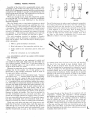
quite easy to master. There are four steps to making a good
solder cOlUlection:
WRONG
One of the best ways to make a good mC'chanical connection
is to bend a small hook in the end of the wire. and then to
crimp this hook onto the terminal to be connect('d. Th~
amount of bare wire exposed at the end nC'cd not be exactly
~/l-inch; however, if it is too long, there is dane:cr of the
eXCf>SS touching another terminal or the chassis. There is
no need to wrap the wire around the terminal mon' than
one time. as this makes a connection that is much mon:
difficult to remove if an error has been made.
1. Make a good mechanical connection.
2. Heat both parts of the connection with the iron.
3. Apply solder to the connection until it melts and
runs.
4. Allow the connection to cool undisturbed.
ALL SOLDERING MUST BE DONE WITH ROSIN
CORE SOLDER.
There is no warranty on any equipment in which acid
core solder has been used. Make sure that the solder you
use is plainly marked "Rosin Core". If you have solder on
hand of doubtful origin, it is wise to obtain a new roll of
50/50 or 60/40 rosin core solder.
Whenever a connection is to be soldered, the instructions
indicate this by the symbol (S). If this symbol is not
shown after a step, further connections must be made to
the same point before soldering.
A number of steps in the instructions begin, "Connect
one end of a wire ...... with the length of the wire specified.
In each case, first cut a piece of wire to the correct length
from the roll supplied with the kit. and then remove about
l/~" of insulation from each end before making the connection. The leads on components should be trimmed as they
are used, the length chosen being that which permits a connection to be made from point to point without strain on
terminals or components. The lead "dress", that is, the
maJmer in which the wiring is arranged as it goes from one
point to another, should follow that shown in the pictorial
diagram as closely as possible. Care must be exercised to
see that un insulated wires do not touch each other, and
cannot do so through vibration or sagging. unless, of course,
they are connected to the same point. It is especially important that uninsulated wires and component leads or terminals do not touch the chassis or bottom plate accidentally.
Check your work after each step. and, when you are satisfied that it has been correctly done, mark the space provided and go on to the next step. Examine the pictorial
diagrams often; if you check your work methodically. your
amplifier should work as soon as the wiring is complete.
4
To transfer heat from t.he iron to the wire and terminal.
the tip of the iron should be kept brightly tinned with
solder. If this is properly clone the fIrst time the iron is
used, the tinning may be mainl1.ined by wiping the tip with
a cloth or sponge ev('ry few minutes while soldering. Wh~n
correctly tinned, the tip will hea t both parts of the mnnection almost immediately. Solder should then be appliC'd
directly to the pal'ts to be soldered, as shown in the middle
illustration above, and both iron and solder removed as
soon as the solder flows freely.
The circuit hoards of the StNeo 35 an~ supplied with all
components (resistors and capacitors) already mounted
and solden~d in place. The circuit boards arC' connected to
the other sections of the ampli fier channels by soldC'ring
wires to eyelets on the boards. These (~yelets, which are
numbered for identification, are filled with sold~r already.
To solder a wire to them. they are first heated with the tip
of the iron, and the end of the win~ inserted as soon as the
solder in the eyelet flows. A correctly macle connection looks
like the illustration 3t the right. above, which shows a smooth
transition from eyelet to wire.
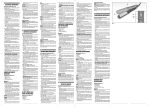
MECHANICAL ASSEMBLY
LEFT 3-SCREW TERMINAL STRIP
GROMMET
FUSE
HOLDER
RIGHT 3-SCREW TERMINAL STRIP
e
<6
~
e
GD
Z-565
OUTPUT
TRANSFORMER
(LEFT)
~
V-2
6BQ5@
GD
@
7247
®
®
0
@
Z-565
OUTPUT
TRANSFORMER
(RIGHT)
PA-774
POWER
TRANSFORMER
9
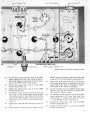
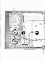
Pictorial Diagram
# 1:
CHECK PICTORIAL DIAGRAMS # 1 AND #3
BEFORE AND AFTER DOING EACH STEP.
I ( ) Mount the two 3-screw terminal strips on the outside of the chassis in the cutouts provided, using
#4 screws, nuts and lockwashers (the smallest size
supplied). The pictorial diagram shows the correct
orientation of the terminal strips.
2 ( ) Mount the fuse holder in its cutout, fastening it in
place with the circular brass threaded ring_ The rubber washer goes on the outside of the chassis; by
maintaining pressure against the fuse holder from the
outside, with one hand, while tightening the brass
ring with the other hand, the fuse holder can be
mounted securely without tools. Be sure that the
fuse holder terminals are oriented exactly as shown
in the diagram. After mounting, terminal lug B
should be bent away from the body of the fuse
holder at the angle shown in the pictorial diagram.
3 ( ) Mount the 5-lug terminal strip on the side of the
chassis, as shown in the diagram, using a #4 screw,
lockwasher and nut.
4 ( ) Install the four sockets supplied for V-2, V-3, V-5
and V-6 011 top of the two PC-13 circuit boards. Note
that the sockets are not all installed in the same way;
pictorial diagram #2 shows the correct orientation
for each socket. Mount each socket with two sets
of #4 hardware. Do not over-tighten.
5( ) Mount the two PC-13 circuit boards in the rectangular cutouts at each end of the chassis; note that the
boards are mounted from the inside of the chassis.
Before mounting each board with four sets of :it4
hardware, study the diagram to be sure that the
boards will be properly oriented on the chassis.
6 ( ) Install the two input sockets from the inside of the
chassis, using two sets of #4 hardware to mount
each socket. The long (center) lug of each socket
should be closest to the circuit board.
Top view of chassis.
7(
~
V-5
6BQ5§
(Jj)
I
I
CIRCUIT BOARD (LEFT)
LEFT INPUT SOCKET
r
'2)
@
7247
e
CIRCUIT BOARD (RIGHT)
RIGHT INPUT SOCKET
) Mount the filter capacitor in the cutout provided.
First, look at the symbols stamped in the plastic
at the base of each connecting lug; these must be
oriented as shown in the pictorial diagram. Insert
the four mounting lugs of the capacitor in the slots
and then twist each of th moun ting lugs one-quarter
turn with a pliers while holding the capacitor snugly
against the chassis with your other hand.
8( ) Pass the leads of one of the output transformers
(marked Z-565) through the two holes provided in
the chassis. The orange, black and yellow leads go
through the hole closest to the center of the chassis,
as shown in the diagram. Mount the transformer
loosely with four #8 screws, nuts and lockwashers
(the largest size supplied). After adjusting its position so that it is as close to the circuit board as
possible, tighten the screws.
9( ) Pass the leads of the other output transformer
(Z-565) through the two holes provided in the
chassis, again observing that the black, orange and
yellow leads go through the hole closest to the center
of the chassis. Mount the transformer loosely with
four sets of #8 hardware, position it as close to the
circuit board as possible, and tighten the screws.
IO( ) Pass the leads of the power transformer (PA-774)
through the two holes provided at the center of the
chassis. A group of four leads go through the hole
nearest to the fuse holder, and five':' leads throllgh
the othel- hole. Mount the power transformer with
four sets of #8 hardware, but do not tighten the
screws immediately. First, center the power transformer so that it is evenly spaced between the two
output transformers. Then, tighten the screws.
H(
Insert the rubber grommet in the hole in the chassis
through which the line cord is to pass.
·Seven leads in 2,10- ....olt transformer PB-028. for lI~C outside the Unilt'd
States. Special instructions [01' in::ilaliinJ! PU·U28 bel!in at the ('on·
elusion of these instructions.
5
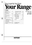
WI.!UNG INSTRUCTIONS'. '
LEFT CIRCUIT BOARD
)
,n
When cutting transformer leads to correct length,
strip the insulation at the end of each lead to expose
about 114" of wire. Tin the exposed end, by heating
it with the soldering iron and melting bit of solder
onto it; this wiI1 keep the end from fraying, and
permits a more secure mechanical connection. Measure the length with a ruler, from the chassis to the
end of the lead..while holding the lead straight out
from and perpendicular to the" chassis. Cut one of
the black leads to 11/2 " in length, and connect it to
lug #4 of· the 5-lug terminal strip. Do not solder;
remember, a connection is only to be soldered when
the symbol (S) is printed after the instruction.
a
2( ) Cut .~other ,black lead to 3lJ2", and connect it
to termmal Bof the fuse holder (S).
.
3 (. ) Twist ~ether the two red power transformer leads..
Connect' one of them. to lug # 1 of the 5-lug terminal
strip.
.
4( ) Connect the other red power transformer lead to lug
'#2
of the 5-lug terminal str~p.
5( ) Cut the 'red:ahd-yellow power transformer lead to
'. 3lJ2" in length, and connect it to chassis-mounqng
lug A of the filter capacitor.
6(
'
. 7( ,) Connect the green power transformer lead to pin #4
ofV-3. IMP"ORTANT:'
Because the tube ~ocket lugs
~:.' '. are smill( 'a~d closely spaced;' it', is imperative that
" all'connections' to them be made with care. Keep
stripped wire ends as short as possible;' insert them
in the lugs 'up to the insulation; cut off excess imme-diately' after soldering each connection; check each
time to be certain that nearby terminals and hardware cannot accidenta.Jly be touched. by bare wire
ends,
8(
LEFT 3- SCREW TERMINAL 51
The four remaining power transformer leads are connected next. Cut the green and green-and-white
leads to 6" each. and twist them together, as shown
. in the diagram. Connect the green-and-white lead to
pin #5 of V-3 on the LEFT circuit board.
Cut the brown and the brown-and-white power
transformer leads to 6". Twist them together, and
connect the brown-and-white lead to pin #5 of V-6
on the RIGHT circuit board.
9(
Connect the. qrown power transformer lead to pin
#4 of V-6.
I
lOr ) The LEFT output transformer leads are connected
next. Carefully cut the blue-and-white. and green6
,
/
.and-white leads from the LEFT output transformer
to exactly 2" in length. 'Strip and tin the ends, and
-' 'twist the' leads together, as" in the diagrain; Connect
the blue-and-white lead to pin #7 oc' V -2 on the
LEFT circuit boa~d (S).
• ':. -:l'
11 (
Connect the green-and-white lead to pin #9 of V-2
(S) .
12 ( ) Twist together the blue and green leads from the
LEFT output transformer. Connect the bll;le lead tq
pin #7 of V-3 on the LEFT circuit'board (S),
13 (
Connect the green lead to pin # 9 of V-3.
14(
Connect the red lead (rom the LEFT output transformer to lug #2 of the filter capacitor. This is the.
lug next to the square symbol on the plastic underside of the capacitor, and should be in the position
shown in the pictorial diagram,
Ci
5-LUG TERMINAL STRIP
:~
RIGHT 3-SCREW TERMINAL STRIP
Pictorial Diagram #2: Wiring of transformer leads.
15( ) Cut the black, orange and yellow leads of the LEFT
output transformer to 3 112" long. Twist all three of
these leads together, and connect the black lead to
lug C of the LEFT 3-screw terminal strip.
16(
Connect the orange lead to lug 8 of the LEFT
3-screw terminal strip (S).
17 (
Connect the yellow lead to lug 16 of the LEFT
3-screw terminal strip.
IS!
The RIGHT output transformer leads are connected
next. First, cut the blue-and-white and green-andwhite leads to exactly 2" long. Strip and tin the ends.
and twist the leads together. C0nnect the blue-andwhite lead to pin #7 of V-S on the RIGHT circuit
board! S).
19(
RIGHT output transformer. Connect the blue lead
to pin #7 of V-6 on the RIGHT circuit board (S).
21 ( ) Connect the green lead to pin #9 of V-6. Be sure
that exposed wire ends or stray filaments from them
cannot touch other wires or terminals, or cause a
short-circuit to -the chassis or hardware.
22 (
23 ( ) Cut th€ black, orange and yellow leads of the RIGHT
output transformer to 3 1/ / ' long. Twist these three
leads together, and connect the black lead to lug
C of the RIGHT 3-screw terminal strip.
24(
Connect the green-and-white lead to pin #9 of V-S
(S) .
20 () Twist together the blue and green leads from the
Cut the red lead from the RIGHT output transformer to 4V2" long, and connect it to lug #2 of the
niter capacitor (square symbol).
25 (
Connect the orange lead to lug 8 of the RIGHT
3-screw terminal strip (S).
Connect the yellow lead to lug 16 of the RIGHT
3-screw tel'minal strip.
7
REFER TO PICTORIAL DIAGRAM ;:r3.
26 ( ) Connect one nd of the 6S00-ohm (bi ue. gray, red).
1-watt resistor to lug ;;2 (square symbol) of the
filter capacitor. Connect the other end to lug #3
( triangle symbol) of the capacitor. The resistor leads
should be cut to permit mounting exactly as is shown
in the diagram.
27( ) Connect one end of the 50-ohm, 5-watt resistor to
lug # 1 (curved line symbol) of the filter capacitor.
Connect the other end to lug :#I 2 (square symbol)
of the capacitor (S). Check to be sure tha t all four
of the connections at lug #2 have been solden~d,
and that excess wire has been trimmed away, and
cannot touch the chassis or adjacent lugs.
2S( ) Connect one end of the 95-ohm, 5-watt resistor to lug
#4 (no symbol) of the filter capacitor. Connect the
other end to chassis-mounting lug B of the capacitor.
29 ( ) Connect one end of a 5/' wire to chassis-mounting
lug B of the filter capacitor (S). Connect the other
end to lug #3 of the 5-lug terminal strip (S).
30( ) The silicon rectifier diodes supplied with the kit may
be of any of the three types shown in the illustration;
although differing in external appearance, the three
types are electrically equivalent.
Connect the CATHODE lead of one
of the rectifier diodes to lug # 1
(curved line symbol) of the filter
capacitor. Connect the ANODE lead
to lug -# 2 of the 5-lug terminal strip
r 8). IMPORTANT: Arrange the
-·E-- diode leads exactly as shown in the
pictorial diagram. When soldering,
hold a pliers on the lead between the diode body and
the solder connection to avoid application of excessive
heat to the diode.
31 ( ) Connect the CATHODE lead of the other rectifier
diode to lug # 1 (curved line symbol) of the filter
capacitor (S). Connect the other lead to lug # 1 of
the 5-lug terminal strip (8). Observe the same precautions when soldering as in the preceding step.
32 ( ) Connect one end of a 4" wire to lug C of the RIGHT
3-screw terminal strip (8). COlUlect the other end
to chassis-mounting lug A of the filter capacitor.
33( ) Connect one end of a 9" wire to lug C of the LEFT
3-screw terminal strip (S). COlUlect the other end
to chassis-mounting lug A of the filter capacitor
(S) .
34 ( ) Connect one end of a 4" wire to lug # 3 (triangle
symbol) of the filter capacitor. Connect the other end
to eyelet #7 of the RIGHT circuit board (8).
NOTE: Before making a connection to an eyelet on the circuit board, tin the end of the wire
by heating it with the soldering iron and touching solder to it. The wire end is tinned when
the solder melts and runs onto the wire. The
eyelets on the board already have solder in
them. To solder to the eyelet, heat it with the
soldering iron and insert the end of the wire
when the solder in the eyelet flows. Remove the
iron and hold the wire in place until the solder
hardens.
35 ( ) Connect one end of a 5" wire to lug #4 (no symbol)
of th filter capacitor. Connect the other end to pin
;;3 of V-5 on the RIGHT circuit board.
36 ( ) Prepare a 13/1" piece of wire by stripping 112" of insulation from one end, and II," from the other end.
8
Push the longer bare end through pin =3 of V-6 on
the RIGHT circuit board (8), and bend it around
to conn ct to pin ;:;4 of V-6 also. Connect the other
nd to pin # 3 of V -5 (8).
37 ( ) Connect one end of a 4 V2" wire to eyelet #4 of the
RIGHT circuit board (8). Connect the other end
to eyelet # 10 (8).
3S( ) Twist together a 2 1/ 2 " and a 4" wire so that one pair
of ends is even. Connect the matching ends to pins
#4 and ¢j:!) of V-;) on the RIGHT circuit board.
Connect the shorter of the remaining ends to eyelet
#5 (S), and the longer remaining end toeyel t =3
(8) .
39 ( ) Twist together a pair of 2 1/ 2 " wires. Connect one
pair of ends to pin #4 (8) and pin :;:S (8) of V-S
on the RIGHT circuit board. Connect the other ends
to pin #4 (8) and pin #5 (8) of V-6.
40(
Connect one end of a 7" wire to lug 16 of the RIGHT
3-screw terminal strip (S). Connect the other end
to eyelet #6 of the RIGHT circuit board (S).
41 ( ) Connect one end of a 1 11i" wire to pin # 9 of V-6
on the RIGHT circuit board (8). Connect the other
end to eyelet # 11 (S L
42 ( ) Connect one end of a 1" bare wire to pin # 2 of V-6
on the RIGHT circuit board (8). Connect the other
end to eyelet #9 (S).
43( ) Connect one end of a 1" bare wire to pin #2 of V-5
on the RIGHT circuit board (S). COImect the other
end to eyelet #8 (S).
44 ( ) Connect one end of a 1" wire to the long lug of the
RIGHT input socket (8). Connect the other end
to eyelet #1 (S).
45 ( ) Connect one end of a 11/ 2 " wire to the short lug of
the RIGHT input socket (S). COllilect the other end
to eyelet #2 (S).
46( ) The next group of steps are performed on the LEFT
circuit board. Connect one end of a 12" wire to lug
# 3 (triangle symbol) of the filter capacitor (8).
COlUlect the other end to eyelet #7 of the LEFT
circuit board (S).
47 ( ) Connect one end of a 10" wire to lug #4 (no symbol) of the filter capacitor (S). Connect the other
e~d to pin #3 of V-2 on the LEFT circuit board.
48( ) 8trip 112" of insulation from one end of a 1%" piece
of wire; strip about VI" from the other end. Push the
longer bare end through pin #3 of V-3 on the LEIT
circuit board (S), and then bend it back to connect
it to pin #4 of V-3. Connect the other nd to pin
#3 of V-2 (S).
49 ( ) Connect one end of a 4 Ih" wire to eyelet #4 of the
LEFT circuit board (8). Connect the other end to
eyelet #10 (8).
50 ( ) Twist together a 21;2" and a 4/1 wire, so that one pair
of ends is even. Connect the matching ends to pins
#4 and #5 of V-2 on the LEFT circuit board. Connect the shorter of the remaining ends to eyelet # 5
(8), and the longer end to eyelet #3 (S).
51 ( ) Twist a pair of 2 112/1 wires together. Connect one pair
of ends to pin #4 (8) and pin #5 (8) of V-2 on
the LEFT circuit board, and the other ends to pin
#4 (S) and pin #5 (S) of V-3.
52( ) Connect one end of a 5" wire to lug 16 of the LEFT
3-screw terminal strip (S). Connect the other end
to yelet #6 of the LEFT circuit board (S).
'onnl'ct one end of ~l 11 I" wire lo pin :.::-9 of V<3 on
the LEFT circuit hO:lrd '. S:, COIllWct thf' ot!wr end
to eyelet == II,S) ,
,J'!' , COnIH'ct 011(' ('nd of a 1" bare wire to pin =:2 of V-:3
on the' LEFT circlIit hoard (S), Connl'ct the otl1('r
I'nd to f'yP1ct ;;L!) l S) .
;),'i,
COnIwct 011(' ('oc1 of allother I" bal'l' wire to pin :;::2
of V -~ on II\(' LEFT circuit hoard : S). Connect the
other end to eyeld #8 IS).
;)6,. ) f:onnect one end of :J 1" wire to thl' long- lug of the
LEFT input socket IS,. Conncct the other ('ncl to
('yf'let ;; L . S ".
f)i
('onm'd onl' elld of ;\ 11/~" wire to the short lug of
tl1(' LEFT input sockel is'. Connect the other end
to eyelet :.::-:2 IS).
.j'"
Ins!'rt the line cord through the rubber grommd
lnountl'd on thl~ chassiii, und push it through far
('nough to tie a kno/. about ;)" from the pnd. Tie thp
knot. Thl'n, >,;eparate 01(' two conductors of the lint·
cord for :.lbOllt 4". Cut 11i~" from onc of them, and
stri p and tin lhe ('nds of both.
;-)!l
! CO!Hwct th,' long-er of the two lirH~ cord conductors
to lug =::-4 of th" i)-lug- terminal strip I S I. Connect
th(, otlwr conductor to lug A of th<' fuse holdpr (S).
This completes the wirin~ of the Stereo 3f).
,J;;
i
PLACES TO DOUBLE-CHECK AFTER WIRING
Be sure that all mounting screws ilnd nuts are tight.
Compare the wiring of ('Jch of the tube sockets to that
shown in thp pictorial diagram. All connections should
be seclll'ely soldNed, with enough space between conn(,etions to the tube pin lugs so that there is no chanc0
of an ::lccidental short-circuit.
i Compare the wiring to each lug of thC' filter capacitor
with that shown on the diagram. Check carefully to see
that all connections are soldered, and that excess lead
IC'ngth has not caused any connection to short-circuit
to thf, cbassis. Count the wires going to each terminal
on diagram nnd amplifier.
\ UsC' special care in eXHmining all connections, to be sut'(,
that none of them are high enough to touch the bottom
platf' when it is installed. Chpck the ;:i-lug terminal
strip and filter capilcitor closely.
The tubes and fusc may now hI' installed. The sockd on
rach board which is supplied already mounted is for the
1247 tubl'. Each of the two sockets installed and wired
during assembly receives one of the 6BQi) tubes. 1M PORTANT: When inserting the tubes in their sockets for the
first tim(', the socket should be supported from below to
avoid strain on the circuit bOilrd, due to the tight fit of new
sockets. The amplifier a.c. cord should NOT be plugged
into a wall outlet until aftcr the tubes arc installed, and
the cover and bottom plate an' securely in place.
The cov('r and bottom plate arc aUached at the same
tirm~. by s(~tting the amplifil'r chassis on the bottom plate,
which fits inside the chassis. and then lowering the cow'!'
onto the chassis. The thrcE' pieces are fastelwd together by
four sheet mdal scr('ws through the sides of the chassis. The
four rubhE'r feet arc installed by pressing them into the
corn('r ho!<'s of thl' bottom pIntC'. Tlw cover should be used
w!wne-vpr tl1<' :lInplifkr is o]J('ratl~d where it may be touched
accidentally; not only do the tubes bl,~CorIW quitt> hot in
operation. but some points on the circuit board carry a
voltage which, while not lethal, can be quite uncornfortahl('
if touched while the amplifilT is on.
r1
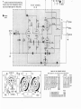
SPECIAL INSTRUCTIONS FOR OPTIONAL
120-240 VOLT POWER TRANSFORMERS
8LAC~
9LACK
VIOLET
VIOLE T
aWHITE
a WHITE
1
BLACK
BWHITE
,
BLACK
B WHITE
~
VIOLET
VIOLET
120-volt
240-voll
Dynakit Stereo ;1;) amplifiers suppli(~cJ with POWN transformer PB-02S can be win~d for lise with (·ithc-r 120- or
240-volt a.c. power sourcf's. in lhe followin~ w;~y:
For 120-volf operation.
Begin with the group of scvC'n Ir'ads from thr pOWl'r
transfonm·r. all of which should come through tb(~ hok
in the chassis farthest from the fust' holder. ('ol1lwl't
the black lead to tcrmin;)l B of the fus(' hold0l',
Connect the black-and-whitl' lcad to tr'rmina) B of tlw
fuse holder (S;.
I ) COnJ1l'ct the vio!rt lead to lug ;;:4 of the .j-lug tt'rminal
strip.
Connect the vioJt>t-and-whitl' lead to lug ;;:4 of the
5-lug terminnl strip.
Proceed with the wiring sters in th(' regubr ass('mhly
portion of this booklet, beginning with wiring step :# :1.
For 240-volt operation.
( ) Connect the violet-and-whi te lead to lug ;:.) of the
i)-lug terminal strip.
Connect the black-and-white kitd to lug ==5 of the
;J-lug t0rmino.I strip (S).
Connect the bbck ll,acl to terminal B of the fusp holdN
(S).
Connect the viold lead to lug ;;:,t of Uw .J-lug terminal
strip.
Proceed with the wiring steps in the regular assembly
portion of this hookkt. hl'ginning with wiring step # 3.
INSTALLING THE STEREO 3S
In addition to the Stereo :l5, your complete stereo system
will includf> one or more signal sources I turntabll'. tUI1l'r,
tape transport) , a stereo preamplifier (unless included with
the signal source), and two loudspeakers.
Installation of the Stereo :~5 is simrle. You will need
two shielded audio cables for the inputs (usually provided
with the preamplifier) and two lengths of two-conductor
wire with which to make the connections to the loudspeakers. Ordinary lamp cord will do for the latter.
The Stereo 3,5 is d('signrd for use with stereo pn':llnplifu'rs which have their own power supply, such as th(' Dyna
p AS-3. In addition to a high II~vel of performance, the
preamplifier should he capable of delivering a signal of
about L volt to drive the Stereo 3.') to its full output. '1'111'
Stereo 3:> a.c. lint' cord should he connected to a switched
auxiliary a.c. outlet on the preamplifier; in this way, it
.will be turned on and off automatically when the prf':llnplifier is switched on and off. Since the Sterpo ;3;) contains its
own fuse, an outlet which is not fuspd may be used.
9
The St('rl'n :J;i may also hi' u~('d with an F ~I tUON
without 01'('(1 for :l !In'ampliftrr, prnvidpd that tlw tunpr
is equiPl)('d with a volume control and 5witchl'r1 a.c. outld,
:md ha:; an output of :It 1(';\5t 1 volt.
T!w loudsp('ak~'rs chosen may be of JllY iTl1]1('danc(~ or
efficipncy, since thc' Stcn'o :~[) has sufficient pOWI'r reserv{'
bc~yond that usually rl'quil'('d for home listening so that no
lack of volume is likely to bl' oosNv('d, ('v('n with I'l~btivdy
incfficil'nt spl'akers. Thc' !oudspeflkpr connection (or pach
channpl is made b('twecm tlw COM (common) and either
the 8- or 16-ohm tap provided; the bottom pbt(~ is print('d
to ident.ify thc'se tl'rrnin:1ls. The S-ohm tap wiH permit
satisfactory op('r:ltion with loudspl'o.kers of 4- t.o 12-ohm
nominal impedancp, whik the H>-ohm tap may be used with
loudspeakers of 12- to :W-ohm rating.
or a sp"cial output on tJwir prc'amplifil'r hy usin~ t!w followiTlg nlC'thod. A monophonic c'xtr'nsion 101ld~T)(';)kl'r may bl'
conn('ctNl to :1. sl.!'rl'o systc'm in thl' ,-;:\111(' way.
T1H' circuit shown hC'1ow providC's OUt.Pllt from a central
loudspf'~k('r with full control over its h'vl'l. For f1E'st results,
thl' speakc'rs uSNl shnuld bc idl'ntical.
BC' cNtain that the loudspeak,,!'.:; ;Ir<~ properly phased.
9 OR 16 n
8 CR 16J1
COM~.ON
PHASING THE LOUDSPEAKERS
Tlw two lourlspf'akers used in ;) stereo system must he
phased propprly (or corre'ct stereo reproduction. The phasing pracc'ss it.s('lf is simple', aftc'r tlw amplific'r is operating
and the two loudsTw~kl'rs a re' conn~ctpd.
Play a monophonic; record, or t.une in a monophonic
broadcast on your tuncI'. As you walk flcross the room in
front of the 10udsTwakers, there should be a smooth, continuous transition of sound from one side of the room to the
oth('r. When you an' directly betw('('n the' loudspr~ak('rs.
the sound should appe:1r to corne from a source that is
directly in front of you, that is, also centered between the
[oudspe'akf'rs. If you hav!' any doubt as to whet.hN or not
the phasing is corl"l~ct. ,'1ftn making this test, transpose' th('
two connections at one of the' ;)mplifier terminal strips; that
is, connect the wire which was connected to "8" or "16" to
"C01\I", ;ll1d vice vns;.l. If you have cbanged to the corrc~ct
phasing, the' sound will now be distinctly centered, o.nd the
bass tones will appc'ar to have increased. If you have'
changed the connection to incorrect phasing, tbe sound
will sc'!'m to jump from one side to the other as you mov/'
slightly to tht' right and left of cente'r.
LISTENING WITH STEREO HEADPHONES
Headphones can be used with the Stereo .'35 in place of
loudspeakers or connectt,d in addition to loudspeakers.
Most headphone manufadurers supply instructions and
special junction boxes which permit direct connection of
headphones to the loudspeaker outputs of the amplifier.
With low impedance headphones (4 to 16 ohm rating)
without instructions from the manufacturer.:l I-watt resistor
oi about 100 ohms should b~ connected in sl~ries with the
outpu t of each channel. This will attenuat0. the si~nal to each
headphone, improving the signal-to-noise ratio.
CONNECTING A THIRD LOUDSPEAKER
TO YOUR STEREO SYSTEM
In most stereophonic systems, the usual arrangement of
two loudspeakers which form an equilateral triangle with
the listener's position will yield optimum performance, In
cases where the program contains exaggerated separation,
judicious use of the blend control on the preamplifier will
provide a more natural and pleasing effect.
When room arrangement or size does not permit the ideal
placement of loudspeakers, the addition of a third loudspeaker, playing a combination of the left- and rightchannel material, may improve the spatial effect considerably. Those listeners who feel a need for a third loudspeaker,
can try this arrangement without need for a third amplifier
10
IN CASE OF TROUBLE
The StC'l'e:o 3;) has been c::lre(ully engilwl'rc'd to give
long, trouble-free sNvicp. However, a mistake in assembly
or a dde-dive component C:1!1 afTel't its pl'rformance or
make it inoper;ltivc'. If difficulty is ('ncountC'red, a method·
iCfll ;lnalysis of the trollbl,' will usually Ic~ld to a quick
CUrt'. The: first thing to check is thC' wiring t.o be' surC' that
all of Uw steps havC' \)('C'n p"l'formed, ;\nd that all connections
ho.ve been ,~oldc'r('(l. It is especially helpful to have someone
other than the builder do the checking.
If the tubes do /lot light at all (on both channels), it is
likely that a.c. power is not being delivered to the amplifier.
In all likelihood, the fuse will have blown, indicating the
possibility of a short-circuit in eithN the fil.1ment or high
voltage supply lines. If tlw r<,sistlnce Iwtwf'cn ehasgis
ground ilnd the quad filter capacitor lugs is less than
100,000 ohms, this indicates a probable short-circuit in
the high-voltage supply,
If the tube,~ of one channel h;;ht, but those' of t.he other
do not, the filament IC:1ds from the power transformer to
one of the circuit boards are probably not properly conneet.ed, or these may be defective in the power transformer.
If (Ill tubes light but one, the tuhl' in qUl'stion should b<~
interchanged with one of the same type from another socket
on eitber board. This should show whethc'r the tube or
its associated circuitry is at falI1t; if the tuhe still fails to
light, it is faulty. II' it lights in its nr'w position. and the
tube inSNted in its place is now dJrk, a close examination
of the tube socket wiring will usually reveal the' source of
the difficulty. Should an output tuLt' {6B(1.'i) ever require
replacement, it is preferable, but not cssl'ntial, that thl'
pair be rep1.1ce'd.
If all of the tubes light, hut Uwrc is no sound from th('
loudspeakers when the systr~m is in operation, it is first
necessary to <'liminate other c:omponL~nts in tlw system as
possible causes of the trouble. InsL'ding or removing th<'
inpu t plugs at the input sockets of the Stereo .35, while it
is on should produce a loud momentary hum or "thump",
If the loudspeakers are properly connected, and no noise
is produced by inserting or removing the input plugs, the
high voltage supply is probably not connected. Check the
wiring around the quad filter capacitor. If one channel
plays, and the other does not, check the signal path in the
defective channel, as well as the high voltage supply. Another possibility is that strands of wire from the output
transformer leads going to the output terminal strip are
accidentally shorting, or that the wires leading to the loudspeakers are touching the chassis or each other.
If hum and nol.", are present to :my unusual clE'!:;n,<".iir~t
remove the input plugs from tlw St<'rC'o :3;;, and rcp!:lcC
them with short-circuited input plugs I or t<~mp()rarily connect a jumper betwcn eyelets 1 ;md :2 on each circuit
board). If the hum and noise become virtually inaudible,
the amplifier is probably working properly, and the cause
should be sought elsf~wh(~re in the system. Tf plainly audibll"'
hum or noise p<'rsist. there may be an error or defpctive
component in the pow('r supply, or an open ground connection. If the hum is in one chanrwl of the :1mplitier only,
chC'ck to see that eyelet -:;'2 of its circuit board is soldered
to the input ground lug. Occa.sionally. u had tubC' will cause
this condition, which is easily detertflined by switching
tubes until the hum appears in the opposite channel. Hum
on both channels is probably dl1(~ to .'1 pOWN supply dd(~d,
a bad capacitor section or defective diode.
!lllermiUt'llt hum, noi.,,' or . ,11/,lIce :H0. usually the result
of ;\ poor solder conn<,ction. If the trouhlp occur~ in both
ch311nl'l::i. check the powpr supply first; if in one channel
alon/'. 0x:1minf' tll(' soldN conn/'ctions on that sidf'.
Fibment glow is normal. hut if the platf' I the' largC'
metal area) of a tube tends to glow rpd, either the tube or
its a.ssoci.'lt('rl circuitry is faulty. If :111 four of Ih(' output
tubes glow in this mannl~r. there is a short circuit in eitlwr
thp cathocj,~ (pin ;;::1 of :ll1Y 6Bq;5) OJ' filamcllt (pins ;:;4
:1l1d ;;:-;». or at lug #4 of the filter c3[J:lcitor.
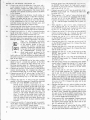
Th<' voltage chart printed alongside the: schf'matic dia..
g'r!llll may be helpful in trouhle-shooting. If readings made
at :3l1Y of the points indicated differ from those list('d by
more than lOU;), it is Ekdy that a wiring error or defective
COlllpOnf'nt is nearby in the circuit.
The Stprco :3::5 should never 1)(' opcr3ted with :my of its
tubes relllOvcd from their sockets.
FACTORY SERVICE AND WARRANTY
The Stereo 3.'i is designed to provide reliable, troublefree performance for a long period of time. when properly
ass,~mbled and installed. It is intendpd for use with the
l~O-volt ;1.C. power supplied to most homes. Although variations of severnl volts abovp or below this figure will have no
pronounc0d et1""d upon lwrformanc/' or comronent life, th('
normal guarantr·c on the equipment is not applicable if it
is operated with a.c. inputs gre.'1ter than 1:30 volts. If yom
local pow('~r is this high or higher in voltage, it is suggested
that a voltage rt"g'ulating or adjusting device be installed
to protect the amplifiC'l".
All parts used in the Stereo 35 ill'(' guaranteed for a
period of one yea r from the cia te of purchase except tul)(',;,
which carry the standard P]cctronic industry (EY A) 90-thy
warranty. Defective parts will be replaced at no charge if
they arc returned prepaid to the factory either directly or
via the dealer from whom the kit was purchnsed. Mnny
Dynakit dealers carry parts in stock which may be used
for replacC'ments. After the guarantee period has passed,
Dynaco, Inc. will supply any non-standard parts used at
net prices. Parts which are standard (resistors. capacitors,
tubes) can generally be purchased from a local electronics
SlI pply storc.
H it is lwliev('d that a transformer is ddective, it should
be disconnected by un~oldE'l'ing, never by cutting its leads
so short that it cannot be re-w;ed.
If the kit has been completely assembled, yet cannot be
made to function properly, or if difficulty is apparent after
a short pNiod of use, W0 will service the kit for a fixed
charge of S6.00, plus the cost of the pmts which al'<~ outside
the warranty aI' have b('('n damaged by the user.
Factory assembled amplifiers include a One-year warranty on labor as well as parts.
Part
I
2
4
2
2
I
2
4
FIXED-CHARGE SERVICE AND
MAINTENANCE ARE NOT A VAILABLE FOR
KITS WHICH ARE INCOMPLETELY WIRED,
OR KITS WIRED WITH SOLDER OTHEH THAN
HOSIN CORE TYPE, OR KITS PHYSICALLY
OR ELECTRICALLY MODIFIED WITHOUT
PRIOR FACTORY AUTHORIZATION. ADDITIONALLY, NO PARTS WILL BE HEPLACED
AND 1\'0 SERVICE MADE AVAILABLE FOR
KITS FOR WHICH THE WARRANTY POST
CARD HAS NOT 8EEN HETURNED. THE
SERIAL NUMBER ON THE FRONT COVER OF
THIS INSTRUCTION BOOK MUST BE MENTIONED IN ALL CORRESPONDENCE .AND IN
ANY CASE WHEHE PARTS ARE RETURNED.
OR KITS SENT OR BROUGHT TO THE FACTORY FOR SERVICE.
It is the factory prerogative to limit til(' service facility
to one year from the dat0 of purchase.
When shipping th0 amplifier to Dynaco, Inc., for servic0,
attach a note specifying the symptoms, th<' name and
address of the sencl('r. ;md the scri:d number of the kit.
The kit ~houlcI be securely packed to withstnnd the abuses
of handling in transit. It should lw placed in a rugged carton surrounded by seven11 inches of shrcdd(~d paper or
other soft packing material. The original bl car/on i~ nol
suitable for shipment of a wirl~d amplifier.
Shipment should be made by prepaid EXPRESS, where
possible; repaired kits will then be rC'turned EXPRESS
C.O.D. for freight and service chargf's (unless these charges
have b('cn prepaid). Parcel post is not u safe method for
the shipment of ass('mblcd kits. and should not be used
for this purpose.
The Dyna Company c:ssumes no linbility or responsibility
for damages or injuries sLlstained in assembly or operation
of this Dynakit.
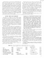
Ports of sll11ilar type which do not change performar~ce will sO;l~·:til11r., be incillot:d ,1, ,1
:nalter of expediency. This Will account for slight variations :n v;iue and appeoran:",
PARTS LIST
Chassis
Cover
Bolto'n plate
Power transformer PA·774
Output trJnsformer Z·565
Output tube 6805/[L84/7189
Driver t1:be 72·17
Recrifir:r diodl~ SOO l11a 1000 piv
Filter capilci(or. quzdruple section
50,'1020 @ tl50 v.; lOO @ 25 v.
Circuit board assembly PC·13
Socket. 9 pin saddle
I~1PORT"'\NT:
Part
~o.
711036
71 !O37
I1l038
46477Jj
tl5456S
SI700S
517006
5t1/1529
297227
557013
399010
Terminal strip. 3 screw
T~rminJI strip, 5 lug
Input sockd
line cord
Wire. hookup
Warranty card
~o.
373003
375001
hiOOl
322092
HARDWARE ENVElOPE
root. (':bller
Fuse, ~ .lmpere ,:u ';i~
Fw.o ho'r.cr W:tll I:ar'!'lii!rc
Gfe·;nlllct,
2')
L:'C,W.1S;Ii'~,
. 0
Loc<w.:q·,:, ,,8
2S
RESISTORS
I 50 ohms, 5wiltts
I 95 ohms. 5 watts
I 6,800 ohms [blue, grJy. red)
:,)"
;;·1
~lil, i1U~gOlill ..(!·!:iO
c. hexagon:Ji. ,,~]?
25 Screw, r:l,lchll~e, ~'/I·:l::, X Ill"
12 Scrr:w. IIl.'1clline. #83? x J/~"
4 Sue"N, 51':ed ,1'.1'1,1[, ';'0
")
'20500
120950
114682
:-,jj)b,~';',
I~U
Part No.
35YL,(;?
3120)0
341,-,:.;:
:..;'j50C3
617:'05
517405
614215
51·\·:G "
51l?15
o114(i<)
61236~
11
"
LEFT
@
@
RIGHT
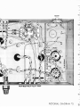
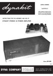
PICTORIAL DIAGRAW\ #3.
-
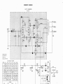
SCHEMATIC DIAGRAM
LEFT CHANNEL
PC-13
~_--4>--Y:..;;E.::..l --I'll
BlK
'-----?-~~
16 n
COM
Voltages .hown
measured from
tube pin to
chossis with YTYM.
VOLTAGE
V-2 V-3
Olii
I
215
0"
112
2
0
0
116 13.5 13.5
3
-,
--,
4 485
TO 9
6.3AC 6.3AC
5 6.3AC
---l
---l
Ollf
O·
6
112
7
370 370
0
0)\0- 0"
8 .85
9
375 375
PIN
V-I
10
CHART
V-4 V-5
O·
230
112
0
116 13.5
--,
465
TO 9
6.3AC
6.3AC
V-6
0*
0
13.5
--,
63AC
--.J
--'
0* 0*
370 370
Olll O~
375
36-
TI
RII
+
~CI
2A
SLO BLO
375
QUAD
2n
RED
4
5
5
4
4
9 GRN/WH
4/5
BRN
V6
5
RIGHT CHAN N E L
PC-13
•
1 V5i V4S! 3II
.5
9 8RN/WH
denotes
eyelets
VEL
IG.Q
OR
8D.
COM
-
@
0
~
C5
1
G
~
0
c:
~ ~~
@~ @4
@2
10
0
I
;-;, 6@
~
C4
F
~~
@~
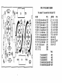
PARTS LIST FOR SCHEMATIC DIAGRAM
Part. marked (,.) are mounted on circuit board PC·13
0
0
RESISTORS
R I' 47K
R 2' 470K
R 3' 1.3K
R 4' 150K
R 5' 300K
R 6' 27K
R 7' 33K
R S' 470K
R g' 470K
RIO' 17K
Rll 6.BK
Rl2 50
RI3 95
'hW
'hW
'/2W
'/2W
'j,W
IW
IW
'hW
'hW
'hW
IW
5W
5W
lO%
10%
5%
5%
5%
SOlo
5%
10%
10%
5%
lO%
10%
5%
11
T2
13
01
02
Part No.
112473
112474
113132
113154
orange, black, yellow 113304
116273
red, violet, orange
orange, orange, orange 116333
yellow, violet, yellow 112474
yellow, violet, yellow 112474
ll3273
red, violet, orange
114682
blue, gray, red
120500
120950
yellow,
yellow,
brown,
brown.
violel, orange
violet, yellow
orange, red
green, yellow
jCAPACITORS
C,' .1 mId
C2' 33 pf
C3' .22 mId
C4, .1 mfd
OS' .1 mfd
, t6' 18 pI
' C7' 27 pf
CSA 60 mfd
CBB 40 mfd
C8C 20 mid
C80 100 mid
Part No,
464774
Power Transformer PA·774
454565
Qulput Transformer Z-565
454565
Output Transformer Z·565
Silicon Reclifler Diode, 500 ma 1000 PIV 544529
Silicon Rectifier Diode, 500 ma 1000 PIV 544529
16 V
500 V
200 V
400 V
400 V
500 V
500V
450 V
450 V
450 V
25 V
Part No.
223104
247330
260224
266104
266104
2471BI
247271
1
f 297227
PARTS LIST 'OR S(Ht:MATIC DIAGRAM
Put NC!,
Tt
T2
TJ
01
Dl
PO'N&t
Tuntlormer PA.,,4
Output rru:Jfolmer Z·!SS
Oulout T1aolfor(JI!f Z·S6!.
464714
4S<l5M
4s.456~
Sil'cOf\ Anillier Olode. !X10 nu loaG ply S44!i}9
SiUcOf\ Redlfier Diode, seo IN lDOO PlY "U!i1l}
SCHEMATIC DIAGRAM
LEFT CHANNEl
PC-13
r-_-t-Y:.::E.=..L-{B
16!l
~_-+..;,;OR4g 8!l
I
I
I
Voltage I Iho .... fI
mea'uted r,o,"
I
L
Illbe pi., to
("'oui. witlol VrVM.
PIN
V-I
I
2
3
215
112
116
",'/ ..
----:.._-
VOLTAGE CHART
V-2 V-3 V-4 V-5
RED
V-6
RII
o
0
112
0
13.5
13.5
I 16
13.5
4
5
0
13.5
-,
---,
6.3AC 63AC
....J
...J
6
7
O*'
370
0*
370
8
9
375
375
TI
RI2
+
ILK
C8B-
0.1
C8D
+
RI3
~
ILK
2A
SlO BlO
4
Ie>
13.5
385
1ll Unused pins may have internal connect ions,
Iherefore some lubes (depending on brand),
moy hove vollages appeal al these poinls.
RIGHT CHANNEL
PC-13
~-~-;-F:
•
denotes
eyelets
I'
I't,.:.;
,.-_-.,...:..:YE:,:.L~tG.n
>----+-"'oR"---{3B!l.
'-----&-=-~~CO
M