1
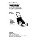
Owner's
Manual
15.5 HP
ELECTRIC
START
42" MOWER
6 SPEED TRANSAXLE
LAWN TRACTOR
Model No.
917.271052
oSafety
,, Assembly
, Operation
o Maintenance
o Repair Parts
]_
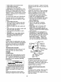
differently from previously built engtnes, Before you start the en- |
This product has a low emission engine which operates
]
gine, read and understand this Owner's Manual.
l
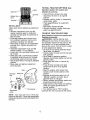
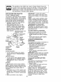
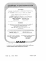
CAUTION:
Read and follow all Safety
Rules and Instructions before
For answers to your questions
about this product, Call:
operating this equipment.
Sears Craftsman Help Line
5 am - 5 pm, Mon - Sat
1-800-659-5917
Sears, Roebuck and Co., Hoffman Estates, tl 60179
Visit our Craftsman website:www,sears,com!craftsman
Warranty ...............................................
2
Safety Rules ......................................... 3
Product Specifications .......................... 5
Assembly ................................................. 7
Operation ............................................. 10
Maintenance Schedule ...................... 16
LIMITED
TWO YEAR VVARRANTY
Service and Adjustments ..................... 20
Storage .......... _..................................... 26
Troubleshooting ......................................27
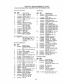
Repair Parts ............................................ 32
Parts Ordering ........................Back Cover
ON CRAFTSMAN
RIDING
EQUIPMENT
PARTS
For two (2} years from the date of purchase, If this Craftsman Rtd]ng Equipment is
maintained,
lubricated and tuned up according to the Instructions
tn the owner's
manual, Sears will repair or replace, free of charge, any parts found to be defective in
material or workmanship.
Warranty service Is available free of charge by taking your
Craftsman rldlng equipment
to your nearest Sears Service Center. in-home warranty
service is available but a trip charge wlll apply. This warranty applies only while this
product is in tile United States,
This Warranty does not cover:
• Expendable
items which become worn during normal use, such as blades, spark
plugs, air cleaners, belts and oil filters.
, Tfre replacement
or repair caused by punctures from outside objects, such as nalts,
thorns, stumps, or glass.
° Repalrs necessary because of operator abuse, including but not limited to, damage
caused by towing objects beyond the capability of the riding equipment,
impacting
objects that bend the frame or crankshaft, or over speeding the engine,
• Repairs necessary because of operator negligence,
Including but not limited to,
electrical and mechanical
damage caused by Improper storage, failure to use the
proper grade and amount of engine otl, failure to keep the deck clear of flammable
debris, or the failure to maintain the equipment
according to the instructions contained in ttle owner's manual.
° Engine (fuel system) cleaning or repairs caused by fuel determined
to be contaminated or oxidized (stale). in general, fuel should be used within thirty (30) days of its
purchase date.
, Riding equipment
used for eommercta! or rental purposes.
LIMITED 90 DAY WARRANTY
ON BATTERY
For ninety (§0) days from date of purchase, if any battery included with this riding
equipment
proves defective In material or workmanship
and our testing determines
the
battery will not hold a charge, Sears will replace the battery at no charge. Warranty
service Is available free of charge by taking your Craftsman riding equipment to your
nearest Seai's Service Center,
In-llome warranty service is available but a trip charge
wil! apply. This warranty applies only while this product ls tn the United States,
To locate the nearest sears service center or to schedule In-home warranty service,
simply contact sears at 1-800-4-my-home
Thts WarrantY gives you specific legal rights, and you may also have other rights which
may vary from state to state,
Sears,
Roebuck
and Co., D/817 WA, Hoffman
Estates,
IL 60179
IMPORTANT: This cutting machine is
capabfe of amputating hands and feet
and throwing ob)ects. Failure to observe
the following safety instructions could
result in serious injury or death.
GENERAL OPERATION
• Read, understand, and foliow all
InstruCtions In the manual and on the
machine before starting,
• Only allow respOnsible adults, who are
familiar with the Instructions, to operate
the machine.
° Clear the area of objects such as rocks,
toys, wlre_ eto,, which could be picked
up and thrown by the blade,
° Be sure the area is clear of other
people before mowing. Stop mact]lne If
anyone enters the area.
° Never carry passengers.
° Do not mow In reverse unless absolutely ne0eSsary. Always look down
and behind before and while backing.
° Be aware of the mower discharge
direction and do not point It at anyone.
Do not operate the mower without
either the entire grass catcher or the
guard In place.
. Slow down before turning,
• Never leave a running machine
unattended, Always turn off blades, set
parking brake, stop engine, and
remove keys before dismounting.
° Turn off blades when not mowing,
° Stop engine before removing grass
catcher or unclogging chute,
• Mow only In daylight or good artiflclaf
light.
• Do not operate the machine while
under the influence of alcohol or drugs.
• Watch for traffic when operating near or
crossing roadways.
• Use extra care when loading or
unloading the machine into a trailer or
truck.
, Data indicates that operators, age 60
years and above, are involved in a
large percentage of riding mowerrelated Injuries. Ttlese operators
should evaluate their abiiity to operate
the riding mower safely enough to
protect themselves and ott_ers from
serious injury.
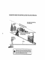
SLOPE OPERATION
Slopes are a major factor related to lossof-control and tlpover accidents, which
can result in severe Injury or death. All
slopes require extra caution. If you cannot
back up the slope or tf you fee[ uneasy on
it, do not mow It.
DO:
• Mow up and down slopes, not across.
° Remove obstacles such as rocks, tree
limbs, etc.
o Watch for holes, ruts, or bumps° Uneven
terrain could Overturn the machine. Tall
grass can hide obstacles.
, Use slow speed, Choose a low gear so
that you will not have to stop or shift
while on Ihe slope,
° Follow the manufacturer's reOommendatlons for wheel weights or counterweights to Improve stability,
, Use extra care with grass catghers or
other attacllments. These can change
the stability of the macl_Ine.
• Keep all movement on the slopes slow
and gradual. Do not make sudden
changes in speed or direction.
• Avoid starting or stopping on a slope. If
tires lose traction, disengage the blades
and pi'oceed slowly straight down the
slope.
DO NOT:
• Do not turn on slopes unless necessary, and then, turn slowly and gradually downhill, if possible.
• Do not mow near drop*ells, ditches, or
embankments, The mower could
suddenly turn over tf a wheel Is over the
edge of a cIlff or ditch, or if an edge
caves In.
° De not mow on wet grass. Reduced
traction could cause s{iding.
° Do not try to stabilize the machine by
putting your foot on the ground,
° Do not uee grass catcller on steep
slopes,
CHILDREN
Tragic accidents can occur if the operator
is not alert to the presence of ct_lldren,
Children are often attracted to the
machine and the mowing activity. Never
assume that clilldren will remaln where
you last saw them.
• Keep children out of the mowing area
and under the watchful care of another
responsible adult.
° Be alert and turn macl]ine off if children
enter the area,
- Keep nuts and bolts, especially blade
attachment bolts, tight and keep
equipment in good condition.
• Never tamper with safety devices.
Check tl_etr proper operation regularly.
, Keep machine free of grass, leaves, or
other debris build-up. Clean oil or fuel
spillage. Allow macl_tne to cool before
storing,
- Stop and inspect the equipment if you
strike an object, Repair if necessary,
before restarting.
• Never make adjustments or repairs with
the engine running°
• Grass catcher components are subject
to wear, damage, and deterioration,
whicll could expose moving parts or
allow objects to be thrown. Frequently
check components and replace with
manufacturer's recommended parts,
when necessary.
o Mower blades are sharp and can cut.
Wrap the blade(s) or wear gloves, and
use extra oautton when servicing them.
o Beforeand when backtng,look behind
and down for small children.
• Never carry chlidren. They may fall off
and be seriously injured or interfere
wkI1 safe machine operation.
, Never allow children to operate the
machine.
o Use extra care when approachlng blind
corners, shrubs, trees, or other objects
that may obscure vtston.
SERVICE
° Use extra care In handling gasoline
and other fuels, They are flammable
and vapors are explosive,
Use only an approved container,
Never remove gas cap or add
fuel with the engine running_ Allow
engine to coot before refueling, Do
not smoke.
Never refuel the machine
Indoors.
Never store the machine or fuel
container inside where there te an
open flame, such as a water healer
. Never run a machine inside a closed
area.
* Check brake operation
.
-
.
•
o
o
frequently.
Adjust and service as required,
Be sure the area is clear of other
people before mowing. Stop machine if
anyone enters the area.
Never carry passengers or children
even with the blades off.
Do not mow in reverse unless absolutely necessary. Always look down and
behind before and while backing.
Never carry children. They may fall off
and be seriously injured or interfere
with safe machine operation.
Keep children out of the mowing area
and under the watchful care of another
responsible adult.
Be alert and turn machine off if children
enter lhe area.
Before and when backing, look belllnd
and down for small children_
o Mow up and down slopes (15° Max),
not across,
° Remove obstacles such as rocks, tree
limbs, eto,
• Watch for holes, ruts, or bumps. Uneven
terrain could overturn the machlne_ Taft
grass can hide obstacles,
° Use slow speed, Choose a tow gear so
that you will not have to stop or shift
while on the slope,
. Avoid starling or stopping on a slope. If
tires lose traction, disengage tl_e blades
and proceed slowly straight down the
elope,
, If machine stops while
uphill,
disengage blades, shlftgl°ttnogreverse
and back down slowly.
• Do nottum on slopes unless neces-.
sary, and then, turn slowly and gradually downhill, if possible,
4
that are recommended by and comply
with specifications of the manufacturer of
your tractor, Use common sense when
towing. Operate only at the lowest
possible speed when on a slope. _bo
heavy of a load, while on a slope, is
dangerous, Tires can lose tractlon with the
ground and cause you to lose control of
y_uwrtractor.
ARNING: The engine exhaust from
tills product contains chemicals known to
the State of California to cause Cancer,
birth defects, or other reproductive harm.
for this symbolto pointout
ImportantSafetyprecautions_it means
CAUTIONI!!BECOMEAWARE!!!YOUR
_FETY ISINVOLVED.
CAUTION: Inorderto preventaccidentel startingwhen settingup, transporting,
adjustingor making repairsalways
disconnectspark plug wire and place wire
_re It cannot contactspark pkJg.
AUTION: Do not 0cast down a hill In
_llUCtrai,you may lose control of the tractor.
AUTION: Tow only lhe attachments
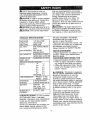
PRODUCT
GASOLINE
1.25 GALLONS
CAPACITY
AND TYPE;
U N LEAD ED
REGULAR
OILTYPE
SAE 10W30 (ABOVE
32°F)
SAE 5W-30
(BELOW 32°F)
W/FILTER: 4,0 PINTS
W/OFILTER: 3,5 PINTS
API-SFiSG/SH):
)I--LCAPACITY:
SPARK
We have competent, well-trained
technicians and the proper tools to
service or repalr this tractor
Please read and retain this manual, The
instructions will enable you tO assemble
and maintain your tractor properly.
Always observe the "SAFETY RULES",
SPECIFICATIONS
PLUG:
CHAMPION
REPAIR AGREEMENT
A Repair Agreement is available on this
product, Contact your nearest Sears
store for details,
CUSTOMER RESPONSIBILITIES
. Read and observe the safety rules.
* Follow a regular schedule in maintaining, caring for and using your tractor.
. Follow the instructions under "Maintenance" and "Storage" sections of this
owner's manual,
RC12YC
GAP: .030")
GROUND SPEED FORWARD:
MPH):
I sT
2 ND
3 a°
4TM
5TM
6 TM
REVERSE',
TIRE PRESSURE:
}YSTEM:
FRONT:
REAR',
1.2
1 o5
2,4
3.5
4.8
5..3
1,5
w_t WARNING: Thls.trac.tor ts equipped,
h an tnternal combustion engine ana
should not be used on or near any
unimproved forest-covered, brushcovered or grass_covered land unless
the engine's exhaust system is equipped
with a spark arrester meeting applicable
local or state laws (if any). If a spark
arres{er is used, it should be maintained
in effective working order by the operator.
In the state of CalifOrnia the above Is
required by taw (Section 4442 of tile
California Public Resources Code).
Other states may have similar laws.
Federal laws apply on federal lands. A
spark arrester for the muffler is available
through your nearest authoilzed service
center/department (See REPAIR PARTS
section of this manual),
14 PSI
10 PSI
...... 3 AMPS BATTERY
5 AMPS HEADLIGHTS
BATTERY:
AMP/HR:
30
MIN, CCA:
240
CASE SIZE', Ut R
BLADE BOLT
TORQUE:
27-_35 FT. LBS.
CONGRATULATIONS
on your purchase
of a Craftsman Tractor. It has been
designed, engineered and manufactured
to give you the best possible depend.ability and performance.
Should you experience any problem you
cannot easily remedy, please contact
your nearest authorized service center.
5
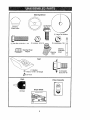
f iii,]1
i,u,
ii
u
Steering Wheel
(t) Hex Bolt
3/8.16 x 1
Steering
Wheel Insert
(t) Large Fiat Washer
@
(1) Hex Bolt 5/16-18 x l-1/4
F[_'_
®
(1) koekwasher
(!) Locknul 5/16-18
3/8
Steerlng
Extension
Shaft
Steedng Wheel
Adapter
..................................
i
i
i
,
i f
.......
I
Seat
@
_(t)
(1) Washer
17/32 × 1-3/16 x 12 Gauge
(1) Shoulder
Bolt 5II6-t8
Knob
Keys
Video
Cassette
i
(2) Keys
Slope Sheet
Your new tractor has been assembled at the factory with exception of those parts left
unassembled for shipping purposes. To ensure safe and proper operation of your
tractor at parts and hardware you assemble must be lghtened securely. Use the
correct tools as necessary to Insure proper tightness. Review the video casselte before
you begin.
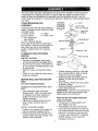
TOOLS REQUIRED FOR
ASSEMBLY
A socket wrench set will make assembly
easier, Standard wrench sizes you need
are Itsted below,
(1) 9/16"wrench
(t) Pliers
(2) 1/2" wrench
(1) Utility knife
(1) 3/4" socket with
drive ratchet
(t) Tire pressure gauge
Wllen right or left hand is mentioned in
this manual, It means, from your point of
view, wlten you are in the operating
position (seated behind the steering
wheel).
TO REMOVE TRACTOR FROM
CARTON
UNPACK CARTON
• Remove al accessible loose parts
and parts boxes from shipping carton,
° Cut, from top to bottom, along lines on
a/four corners of shipping carton, and
lay panels flat.
• Remove mower and packing matedais.
- Check for any additional loose parts or
boxes and remove.
BEFORE ROLLING TRACTOR
SKID
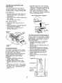
ATTACH STEERING WHEEL
OFF
ASSEMBLE EXTENSION SHAFT AND
BOOT
o Slide extension shaft onto tower
steering shaft. Align mounting holes
in extension and lower shafts and
Install 5/16 hex bolt and locknut.
Tighten securely.
° Place tabs of steering boot over tab
stots in dash and push down to
secure,
INSTALL STEERING WHEEL
• Position front wheels of the tractor so
llley are pointing straight forward.
o Remove steerng wheel adapter from
steering wheel and slide adapter onto
steering shaft extension,
• Position steering wheel so cross bars
are horizontal (left to right) and slide
inside boot and onto adapter.
o Assemble large flat washer, 3/8 lock
washer, 3/8 hex bolt and tighten
securely.
° Snap steering wheel insert into center
of 8teerlng wheel.
• Remove protective materials from
tractor hood and grill
IMPORTANT: Check for and remove any
staples in skid that may puncture tires
wl_ere tractor Is to roll off skld
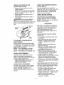
HOW TO SET UP YOUR TRACTOR
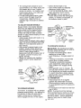
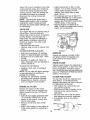
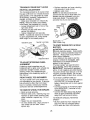
CHECK BATTERY
°Uft seat pan to raised postfon and
open battery box door.
• If this battery is put into service after
month and year Indicated on label (label located between terminals) charge
battery for mlntmum of one hour at 6-.
10 amps, (See "BATTERY" in MAINTE-,
NANCE section of this manual for
charging struelons.)
Seat
Terminal
Battery
Door
Termin_
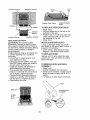
INSTALL SEAT
Adjust seat before tightening adjustment
knob.
° Remove adjustment knob and flat
washer securing seat to cardboard
packlng and set aside for assembly of
seat to tractor.
• Pivot seat upward and remove from
the cardboard packing. Remove the
cardboard packlng and discard.
° Place seat on seat pan and assemble
shoulder bolt. Tighten shoulder bolt
securely,
• Assemble adjustment knob and flat
washer toosely, Do not ttghten,
° Lower seat into operating position and
sit on seat.
° Slide seat until a comfortable position
is reached which ailows you to press
clutch/brake pedal all the way down,
° Get off seat without moving its adjusted
position,
° Raise seat and tighten adjustment
knob securely,
Seat
Shoulder
Bolt
Seat
._
" Rat Washer
Adjustment
Knob
NOTE: You may now roll or drive your
tractor off the skid, Follow the appropriate
Instruction below to remove the tractor from
the skid,
TO ROLL TRACTOR OFF SKID (See
Operation section for location and
function of controls)
. Press lift lever plunger' and raise
attachment lift lever to its highest
position_
° Release parking brake by depressing
clutch/brake pedal.
, Place gearshift lever in neutral (N)
position.
• Roll tractor forward off skid,
• Remove banding holding discharge
guard up against tractor.
TO DRIVE
TRACTOR
OFF SKID
(See Operation
section for location
and
function
of controls)
_LWARNING:
Before starting, read,
understand
and follow all instructions
In
the Operation section of this manual
Be
sure tractor is in a well-ventilated
area.
Be sure the area in front of tractor Is clear
of other people and objects.
• Be sure all the above assembly steps
have been completed°
. Clleck engine oil Ievel and fill fuel tank
with gasoline.
° Sit on seat In operating position,
depress clutch/brake
pedal and set the
parking brake.
• Place gear shift lever In neutral (N)
position,
o Press lift lever plunger and raise
attachment lift lever to Its highest
position.
• Start the engine, After engine has
started, move throttle control to idle
position
o Depress clutch/brake
pedal into full
"BRAKE" position and hold, Move
gearshift lever to 1st gear.
• Slowly release clutch/brake
pedal and
slowly drive tractor off skid,
- Apply brake to stop tractor, set perking
brake and place gearshift lever in
neutral position.
• Turn ignition key to "OFF" position.
Continue With tl_e instructions
that follow,
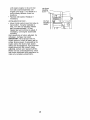
INSTALL
MULCHER
CHECK FOR PROPER POSITION
OF ALL BELTS
See timefigures that ere shown for
replacing motion and mower blade drive
belts in the Service and Adjustments
section of thts manual° Verify that the
belts are routed correctly.
CHECK BRAKE SYSTEM
PLATE
(If previously removed)
- Raise and hold deflector shield in
upright posltlon.
• Place front of mulcher plate over front
of mower deck opening and sllde Into
place, as shown.
• Hook front latch into hole on front of
mower deck.
• Hook rear latch Into hole on back of
mower deck,
s_CAUTJON: Do not remove deflector
ield from mower, Raise and hold
shleld when attaching mulcher plate and
allow it to rest on plate wllile in operation.
After you learn how to operate your
tractor, check to see tlqat the brake ts
properly adjusted, See "TO ADJUST
BRAKE" in the Service and Adjustments
_ectlon of thts manual.
,/CHECKLIS
BEFORE YOU OPERATE AND ENJOY
YOUR NEW TRAOTOR, WE WISH TO
ASSURE THATYOU
RECEIVE THE
BEST PERFORMANCE
AND
SATISFACTION
FROM THIS QUALITY
PRODUCT,
Mutcher
Plate
De
Shield
PLEASE REVIEW THE FOLLOWING
CHECKLIST:
¢" All assembly instructions have been
Completed.
/ No remaining loose parts in carton.
V Battery Is properly prepared and
charged. (Minimum 1 hour at 6
amps).
¢' Seat is adjusted comfortably and
tightened securely.
¢" All tires are properly inflated. (For
shipping purposes, the ttres were
overlnflated at timefactory),
7" Be sure mower deck is properly
leveled slde4o-slde/front-to-rear
for
best cutting results. (Tlres must be
properly Inflated for leveling).
,/Check mower and drive belts. Be sure
they are routed properly around
pulleys and inside all belt keepers.
,/Cl_eck wtrlng. See that all connections
are still secure and wires are properly
clamped
WHILE LEARNING HOWTO USE YOUR
TRACTOR, PAY EXTRA ATTENTION TO
THE FOLLOWING IMPORTANT ITEMS:
,/Engine oil is at proper level.
,/Fuel tank is filled with fresh, clean,
regular unleaded gasoline.
V" Become familiar with ail controls - their
location and function. Operate them
before you start the engine.
¢" Be sure brake system is in safe
operating condition.
Latch
Hooks
TO CONVERT TO BAGGING
DISCHARGING
OR
Simply remove mulcher plate and store
In a safe place, Your mower is now ready
for discharging or installation of optional
grass catcher accessory,
NOTE: It is not necessary to change
blades, The mulcher blades are designed for discharging end bagging also,
CHECKT1RE
T
PRESSURE
The tires on your tractor were ovednflated at the factory for shlpplng purposes. Correct tlre pressure is important
for best Cutting performance.
• Reduce tire pressure to PSI shown In
"PRODUCT SPECIFICATIONS"
section of this manual,
CHECK DECK LEVELNESS
For best cutting results, mower housing
should be properly leveled. See 'qo
LEVEL MOWER HOUSING" in the
Service and Adjustments section of this
manual
9
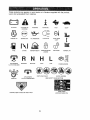
These symbolsmay appearon your tractoror in literaturesuppliedwith tile product.
Learn and understandtheir meaning_
÷
4_
BATTERY
CAUTION OR
WARNING
REVERSE
FORWARD
FAST
SLOW
@
ENG(NE ON
FUEL
CHOKE
ATTACHMENT
CLUTCH ENGAGED
IQNITiON
DANGER
ENGINE O}=F
REVERSE
OIL PRESSURE
UGHTS ON
MOWER HEIGHT
PARKING BRAKE
LOOKED
NEUTRAL
ATTACHMENT'
CLt,YFCH DISENGAGED
H
L
HIGH
LOW
KEEP AREA CLEAR
t[ I_
OVER TEMP
LIGHT
UNLOCKED
!
MOWER LIFT
PARKING BRAKE
SLOPE HAZARDS
(SEE SAFETY R_LES SECTION)
FREE WHEEL
(Automatla Model9 only)
KEEP HANDS AND FEET AWAY
10
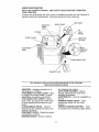
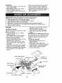
KNOW YO UR TRACTOR
READ THIS OWNER'S MANUAL AND SAFETY RULES BEFORE OPERATING
YOUR TRACTOR
Compare the illustrations with your tractor to familiarize yourself with the i0cations of
various controls and adjustments. Save tIiS manual for future reference.
Light Switch
Ignition Switch
Attachment
Clutch
Lever
Ammeter
Throttle Control
Attachment
Lift Lever
Clutch/Brake
Pedal
Height
Adjustment
Indicator
Parking Brake Lever
Gearshift Lever
Our tractors conform to the safety standards of the American
.................... .....................
N ati0na!StandardS
I=nStitute. .........
AMMETER - Indicates charging (+) or
discharging (-) of battery,
ATTACHMENT CLUTCH LEVER - Used
to engage the mower blades, or other
attachments mounted to your tractor,
ATTACHMENT LIFT LEVER - Used to
raise, lower, and adjust the mower deck
or other attachments mounted to your
tractor,
CLUTCH/BRAKE PEDAL - Used for
declutchtng and braking the tractor and
starting the engtne,
GEARSHIFT LEVER - Selects the speed
and direction of tractor.
IGNITION SWITCH - Used for starting
"
and stopptng file engine.
LIFT LEVER PLUNGER - Used to
release attachment lift lever when
changing Its position,
LIGHT SWITCH - 'Turns the I_eadlights on
and off,
PARKING BRAKE LEVER - Locks
clutch/brake pedal into the brake
position.
THROTTLE/CHOKE CONTROL- Used
for starting and controlling engine speed.
11
The operation of any tractor can result in foreign objects thrown into
the eyes, which can result in severe eye damage. Always wear safety
glasses or eye shields while operating your tractor or performing any
adjustments or repairs. We recommend a wide vision safety mask
over spectacles or standard safety glasses.
HOW TO USE YOUR TRACTOR
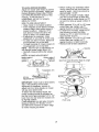
TO SET PARKING BRAKE
Your tractor is equipped wttl_ an operator
presence sensing switch, When engine
is running, any attempt by the operator to
leave the seat without first setting the
parking brake will shut off the engine,
• Depress clutch/brake pedal into fult
"BRAKE" position and hoid.
° Place parking brake lever in "ENGAGED" position and release pressure from clutch/brake pedal, Pedal
should remain in "BRAKE" position,
MaRe sure parking brake wilt hold
tractor
secure,
IMPORTANT: Leaving the ignition
switch in any position otller than "OFF"
will cause the battery to be dlscllarged,
(dead),
NOTE, Under certain conditions when
tractor ts standing idle with the engine
running, hot engtne exhaust gases may
cause "browning" of grass. To eliminate
this possibility, always stop engine when
stopping tractor on grass areas.
.& CAUTION: Always stop tractor
completely, as described above, before
leaving the operator's position; to empty
grass catcher, etc.
TO USE THROTTLE CONTROL
Attachment Clutch Lever
"Engaged" Position
Always operate engine at full throttle.
• Operating engine at less than full
throttle reduces the battery charging
rate,
-Fult throttle offers the best bagging
and mower performance.
TO MOVE FORWARD AND
BACKWARD
The direction and speed of movement fs
controlled by the gearshift lever.
• Start tractor with clutch/brake pedal
depressed and gearshift lever tn
neutral (N) position.
° Move gearshift lever to desired
position.
• Slowly release clutch/brake pedal to
start movement,
IMPORTANT; Bring tractor to a complete
stop before shifting or changing gears.
Failure to do so wilt shorten the useful
life of your transaxte.
TO ADJ UST MOWER CUTTING
HEIGHT
Tile position of the attachment lift lever
determines the cutting height,
, Grasp lift lever.
° Press plunger with thumb and move
lever to desired position,
The cutting height range ts approximately 1-1/2 to 4". The heights are
measured from the ground to the blade
tip with the engine not running. These
heights are approximate and may vary
depending upon soil conditions, height
of grass and types of grass being
mowed.
gaged"
Position
Parking
Brake
gad"
Posltlon
Clutch/
"Br
Position
Position
Ger_rshift
Lever
STOPPING
MOWER
BLADES
-
• To stop mower blades,move attachment clutch lever to "DISENGAGED"
position.
GROUND DRIVE, To stop ground drive, depress clutch/
brake pedal into full "BRAKE" posltton,
o Move gearshift lever' to neutral (N)
position.
ENGINE* Move throttle control to slow position.
NOTE= Failure to move throttle control to
slow position and allowing engine to idle
before stopping may cause engine to
"backfire".
° Turn Ignition key to "OFF" position and
remove key, Always remove key when
leaving tractor to prevent unauthorized
use,
• Never use choke to stop engine,
12
• The averagelawn should be cut to
approximately2-!/2 inches during ttle
coolseason and to over 3 inches
duringhot months. Forhealthierand
better lookinglawns,mow often and
after moderategrowth.
• Forbest cuttingperformance,grass
over 6 InchesInheight should be
mowedtwice, Makethe first cut
relativelyhigh;the second to desired
height,
TO ADJUST
GAUGE WHEELS
Gauge wheels are properly adjusted
when they are slightly off the ground
wlqen mower is at the desired cutting
height In operating position. Gauge
wheels then keep the deck in proper
positton to help prevent scalping in most
terrain conditions,
• Adjust gauge wheels with tractor on a
flat level surface.
- Adjust mower to desired cutting helgl_t
(See "TO ADJUST MOWER CUTTING
HEIGHT" In the Operation section of
this manual),
. With mower in desired height of cut
position, gauge wheels should be
assembled so they are slightly off the
ground, Install gauge wheel in
appropriate hole with shoulder bolt, 3/
8 washer, and 3/8-16 focknut and
tighten securely,
o Repeat for opposite side installing
gauge wheel in same adjustment
hole.
Gauge
Wheel
Mountln
Bracket
3/8,16
Locknut
. Select desired heigllt of cut,
• Start mower blades by engaging
attachment ciutch control.
° TO STOP MOWER BLADES - disengage attachment clutch control,
_, CAUTION= Do net operate the
mower without either the entir e grass
catcher, on mowers so equipped, or
the deflector shield in place.
Shoulder Bolt
Posi_on
Deflector
Shfefd
TO OPERATE
ON HILLS
N: Do
not drive
downdo
_s CAUTI
with Is_pes
greater
thanup.
l b__or
and
not drive across any slope.
, Choose the slowest speed before
starting up or down hills.
* Avoid stopping or changing speed on
hills.
° tf slowing is necessary, move thi'ottle
control lever to slower positio.n.
, If stopping Is absolutely necessary,
_ush clutol_/brake pedal quickly to
rake position and engage parldng
brake,
, Move gearshift lever to 1st gear. Be
sure you have allowed room for tractor
to rol! sllglltty as you restart movement,
° To restart movement, slowly release
parking brake and clutch/brake pedal.
° Make all turns slowly.
TO TRANSPORT
° Raise attachment lift to highest
position with attachment lift control,
Gauge Wheel
° When PUshing or towing your tractor,
be sure gearshllt lever Is In neutral (N)
position.
°
Do not push or tow tractor at more than
TO OPERATE MOWER
five (5) MPH.
Your tractor is equipped with an operator
NOTE,. To protect hood from damage
presence sensing switch. Any attempt by
when transporting your tractor on a truck
the operator to leave the seat with the
or a trailer, be sure I_ood is closed and
engine running and the attachment
secured to tractor Use an appropriate
clutch engaged will shut off the engine.
means of tying hood to tractor (rope,
t3 cord, eta)
TOWING CARTS AND OTHER
system of an engine while in storage. To
avoid engine problems, the fuel system
should be emptied before storage of 30
days or longer. Drain the gas tank, start
the engine and let it run until the fuel
iines and carburetor are empty, Use
fresh fuel next season, See Storage
Instructions for additional information.
Never use engine or carburetor cleaner
products in the fuel tank or permanent
damage may occur,
OAUTION: Fill to bottom of gas tank
filler neck. Do not overfill, Wipe off any
spilled oil or fuelo Do not store, spill or
use gasoline near an open flame.
TO START ENGINE
ATTACHMENTS
Tow only the attacl_ments that are
recommended by and comply with
specifications of tile manufacturer of your
tractor. Use common sense when towing.
Too heavy of a load, while on a slope, is
dangerous, Tires can lose traction with
the ground and cause you to lose control
of your tractor.
BEFORE
CHECK
STARTING
ENGINE
THE
ENGINE
OIL LEVEL
• The engine in your tractor has been
shipped, from the factory, already fitied
with summer weight oil.
• Check engine oil with tractor on level
ground.
, Unthread and remove oil fill cap/
dipstick; wipe oil off. Reinsert the
dipstick into t!_e tube and rest oll flit
cap on the tube. Do not thread the cap
onto the tube. Remove and read oil
level, it necessary,
add otl until
"FULU' mark on dipstick is reached,
Do not overfill.
o For c01d weather operation you should
change 0il for easier starting (See "OIL
VISCOSITY
CHART" tn the Maintenance section of this manual),
° To change engine oil, see the Malntenance section In this manual,
When starting timeenglne for the first time
or If the engine has run out of fuel, It will
take extra cranking time to move fuel
from the tank to the engine.
• Sit on seat in operating position,
depress clutch/brake pedal and set
parking brake.
• Place gear shift lever in neutral (N)
position.
° Move attachment clutch to "DISENGAGED" posltlon_
° Move throttle control to choke position.
NOTE." Before starting, read the warm
and cold starting procedures below,
° Insert key Into lgnltton and turn key
clockwise to "START" position and
release key as soon as engine starts.
DO not run starter continuously for
more than fifteen seconds per minute.
If tile engine does not start after
several attempts, move throttle control
to fast position, wait a few minutes and
try again, If engine still does not start,
move the throttle control back to the
choke position and retry,
ADD GASOLINE
o Fill fuel tank. Use fresh, clean, regular
unleaded gasoline witll a minimum of
B7 octane: (Use of leaded gasoline
will increase carbon and Iead oxide
deposits and reduce valve life), Do
not mix ol] with gasoline, Purchase
fuel in quantities that can be used
within 30 days to assure fuel fresh-
WARM WEATHER STARTING (50 ° F and
above)
o When engine starts, move the throttle
control to the fast position.
• The attachments and ground drive can
now be used. If the engine does not
accept the load, restart the engine and
allow It to warm up for one minute
using the choke as described above.
hess,
IMPORTANT; When operating in
temperatures below 32°F(0°C), use
fresh, clean winter grade gasoline to
help Insure good cold weather startlngo
_lb WARNING: Exp.erlence indicates
that alcohol bleneed fuels [callea
gasohol or using ethanol or methanol)
can attract moisture which teads to
separation and formation of acids during
storage. Acidic gas can damage the fuel
COLD WEATHER STARTING ( 50° F and
I4
below)
. When engine starts, allow engine to
run with the tllrottle control in the
choke position until the engine runs
roughly, then move throttle control to
fast position, Tl_is may require an
engine warm-up period from severat
seconds to several mtnutes, depending on the temperature,
• The attachments can also be used
during the engine warm-up period.
NOTE.' If at a tllgh altitude (above 3000
feet) or in cold temperatures (below 32 F)
the carburetor fuel mixture may need to
be adjusted for best engine performance,
See "TO ADJUST CARBURETOR" in the
Service and Adjustments sectton of this
manual.
° When operating attachments, select a
ground speed tlqat will suit the terrain
and give best performance of the
attachment being used.
f
-,,
MULCHING
MOWING
TIPS
IMPORTANT:
For best performance,
keep mower housing free of built-up
grass and trash, Clean after each use_
• The special mulching blade wilt recut
the grass clippings many times and
reduce them tn size so that as they fall
onto the lawn they will disperse into
the grass and not be noticed. Also, the
mulched grass will blodegrade quickly
to provide nutrients for tl_e lawn,
Always mulch with your highest
engtne (blade) speed as this will
provide tile best recuttlng action of the
blades,
• Avold cutttng your lawn when It Is wet.
Wet grass tends to form clumps and
interferes with the mulching action,
The best time to mow your lawn is the
early afternoon. At this t}me the grass
has dried and the newly cut area will
not be exposed to the dlrebt sun,
° For best results, adjust the mower
cutting helght so that the mower cuts
otf only the top One-third of the grass
blades. For extremely heavy mulching,
reduce your wldtll of out on each pass
and mow slowly.
° Certain types of grass and grass
conditions may require that an area be
mulched a second time td completely
hide the clippings. When doing a
second cut, mow across or perpendicular to the first cut path.
• Change your cutting pattern from week
to week° Mow north to south one week
then change to east to west tile next
week. This will help prevent matting
and gralnlng of the lawn.
MOWING TIPS
- Tire chains cannot be used when the
mower housing is attached to tractor.
• Mower should be properly leveled for
best mowing performance, See "TO
LEVEL MOWER HOUSING" In the
Service and Adjustments section of
this manual,
° The left hand side of mower should be
used for trimming,
• Drive so tllat clippings are discharged
onto the area thathas been cut, Have
the cut area to the right of the tractor°
This will result in a more even distribution of clippings and more uniform
cutting.
o When mowlng large areas, start by
turning to the right so that clippings wllf
dtscllarge away from shrubs, fenceS,
driveways, eto, After one or two
rounds, mow In the opposite direction
maklng left hand turns until finished.
° If grass ls extremely tall, it should be
mowed twice to reduce load and
possible fire hazard from dried
clippings. Make first cut relatively
htglt; the second to the desired height,
• Do not mow grass when It Is wet. Wet
grass will plug mower and leave
undesirable clumps, Allow grass to
dry before mowlng.
- Always operate engine at full throttle
wllen mowing to assure better mowing
performance and proper discharge of
material, Regulate ground speed by
selecting a low enough gear to give
the mower cutting performance as well
as the quality of cut desired,
Max !/3"
15
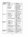
AS YOU COMPLETE
.,___,_'q.
REGULARSERVICE
_,_, _'_/
Check Brake Operation
_
Check Tire Pressure
V'
T
Check Operelor Presence and
tnfatlock By_lerns
R
Check lot Loose Feataners
_Jl
........
_
..................
_ULU_.
_5
Motion Drive Boil(a) Tension
_ '
I
I
I
!_'_
_.
•¢hen_Ee_Jno
oU . .
Clean Air Miler
N
Glean Air Screen
ln_o(
Mul(lory'apalk
_,_
.....
_2
. V ..........
....
_=
Arresla("
I_
Replace Oil Filter (If equipped)
N
_,_
Glean Engine Cooling Fins
.....
V'=
Replace Spelk Plug
,----
V _
'Replace Air Filler Paper Cartridge
Replaea Fuel Filler
....
,I _ i
Check Engine Oil Level.
E
............................
i
__J
!__
Ceogng
Adjust Blade Belt(s) Tension
A_uat
SERVICE DATES
.....
Clean Battery andTerminaIa
Check Transaxle
....
I_
_
0 che_ _tte_ Lev_
R
_,_._R_.'_,?._,S"
_¢:/_"¢;/_y_'fe_Z_Y
"_"
.....
_
"
_. _)_a
mole o(_n what_opomt!(tOill
d#1_m" dully_@n_{Itorl(;
e.,l( elulppOd wile) oil ((lot, chmlgo oil tlvltrf 50 hob'_.
4, Rop(_
bbde_ more oftenv.4_
_n mo_ng Ineandy co)
GENERAL RECOMMENDATIONS
The warranty on this tractor does not
cover Items that have been subjected to
operator abuse or negligence. To
receive full value from the warranty,
operator must maintain tractor as
Instructed in this manual.
Some adjustments will need to be made
periodically to properly matntaln your
tractor.
Art adjustments in the Service and
Adjustments section of this manual
should be checked at least once each
season.
* Once a year you should replace the
spark plug, clean or replace air fUter,
and check blades and belts for wear.
A new spark plug and clean air filter
assure proper air-fue! mi_ure and
help your engine run better and Iast
longer.
BEFORE EACH USE
- Check engine oU level,
° Check brake operation.
° Check tire pressure.
. Check operator presence and
interlock systems for proper operation,
e Check for loose fastenets_
l_,Ht_t(a_uIt
_d IIeIlulpp(;I)
_th mo)_,i_e
_,b_((oi_,
7 _ Tlgh(_n Iront _xle p]vot bQ)l to ._,_€1."(_ _J_I_ur_
Do nol ov_rlbhlg_
LUBRICATION
@ S_
Zerk
CHART
Spindle
Zerk
t%7'
I
@Front Wheel ,-Bearing
Zerk
Bearing Zerk
@Engine _
I
I
I
I
•
_SAE
r_- _
(
J
..i
30 or 10w30
MOTOR
shift
Pivots
OiL,
@GENERAL PURPOSE GREASE
@REFER TO Maintenance "ENGINE" SECTION
IMPORTANT: Do not oil or grease the pivot
_?ints which have special nylon bearings.
scous lubricants will attract dust and dirt
that witl sho_en the life of tl_e self-lubricating bearings, If you feel they must be
lubricated, use only a dry, powdered
graphite type lubricant sparingly.
16
TRACTOR
Alwaysobservesafetyruleswhen
performingany maintenance.
BRAKE OPERATION
If tractor requires more than six (6) feet
stopping distance at hlgh speed In
highest gear, then brake must be adz
justed. (See "TO ADJUST BRAKE" In the
Service and Adjustments section of this
manual),
I]RES
• Maintain proper air pressure In all tires
(See "PRODUCT SPECIFICATIONS"
section of this manual),
° Keep tires free of gasoline, oli, or Insect
control chemicals which can harm
rubber.
• Avoid stumps, stones, deep ruts, sharp
objects andother hazards that may
cause tire damage.
NOTE= To seal tire punctures and prevent
flat tires due to slow leaks, 1ire sealant
may be purchased from your local parts
dealer. Tire sealant also prevents tlre dry
rot and corrosion.
OPERATOR PRESENCE SYSTEM
Be sure operator presence and intertock
systems are working properly, If your
tractor does not function as described,
repair the problem Immediately.
• The engine should not start unless the
clutch/brake pedal is fuliy depressed
and attachement clutch control ls In the
disengaged position,
° When the engine is running, any
altempt by the operator to leave the
seat w thout first se'ding timeparking
brake should shut off the engine,
• When the engine Is running and the
attachment clutch is engaged, any
attempt by the operator to leave the
seat should shut off the engine,
- 1"he attachment clutch should never
operate unless the operator is In the
seat.
BLADE
IMPORTANT'. To ensure proper assembly,
center hole in blade must align wittq star
on mandrel assembly.
° Reassemble hex bolt, lock washer and
flat washer in exact order as shown.
° Tighten bolt securely (27-35 Ft, Lbs,
torque),
IMPORTANT: Blade bolt is Grade 8 heat
treated,.
Mandrel
Edge Up
Center
HoLe
Flat Washer---_-._.
Lock Washer--'>"1_
¢_P--Hex Bolt (Grade)
*A Grade 8 heat treated bolt can be identified
by six lines oh the bOtt head,
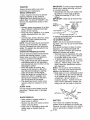
TO SHARPEN BLADE
NOTE= We do not recommend sharpen..
ing blade - but if you do, be sure the blade
ts balanced.
Care should be taken to keep the blade
balanced, An unbalanced btade will
cause excessive vibration and eventual
damage to mower and engine,
° The blade can be sharpened with a file
or on a gdndlng wheel. Do not attempt
to sharpen while on the mower',
. To check blade balance, you wil! need
a 5/8" diameter steel bolt, pin, or a cone
batancer. (When using a cone balancer, follow the Instructions supplied
with balancer.)
NOTE: Do not use a nail for balancing
blade. The lobes of the center hole may
appear to be centered, but are not.
* Stlde blade on to an unthreaded portion
of the steel bolt or pin and hold the bolt
or pin parallel wtth the ground. If blade
ts balanced, it should remain In a
horizontal position, If either end of the
blade moves downward, sharpen the
heavy end until the blade is balanced.
CARE
For best results mower blades must be
kept sharp. Replace bent or damaged
blades.
BLADE REMOVAL
° Raise mower to highest position to
allow access to blades,
• Remove hex bolt, lock washer and flat
washer securing blade.
• Install new or resharpened blade with
trailing edge up towards deck as
shown,
Blade
5/8" Bolt or Pin
Ce
Hole
BATTERY
Your tractor has a battery charging
system which is sufficient for normal use.
However, periodic charging of the battery
with an automotive charger wilt extend
17 its life.
- Keep battery and terminals clean.
• Keep battery bolts tight,
o Keep small vent holes open.
° Recharge at 640 amperes for I hour.
NOTE: The original equipment battery on
your tractor" ts maintenance freer Do not
attempt to open or remove caps or covers.
Adding or checking revel of electroly_e Is
not necessary.
TO CLEAN BATTERY AND TERMINALS
Corrosion and dirt on the battery and
terminals can cause the battery to "leak"
power,
o Open battery box door,
° Disconnect BLACK batlery cable first
then RED battery cable and remove
battery from tractor,
o Rinse the battery with plain water and
dry.
° Clean tem_lnals and battery cable ends
with wire brush until bright,
• Coat terminals with grease or petroleum jelly.
o Reinstall battery (See "REPLACING
BATTERY" in the SERVICE AND
ADJUSTMENTS section of this
manual),
(8) Ilours of operation. Tighten ofl fil! cap/
dipstick securely each time you check the
oll level
TO CHANGE ENGINE OIL
Determine temperature
range expected
before oil change. All oil must meet API
service classification SF, SG or SH,
° Be sure tractor is on level surface,
° Oil will drain more freely when warm.
• Catch oil in a Suitable container,
• Remove oll fill oap/dfpstlck. Be careful
not to allow dirt to enter the engine
when changing oil.
, Remove draln plug.
° After oil has drained completely,
replace olt drain plug and tighten
securely.
, Refill engfne with otl through oll fill
dipstick tube. Pour slowly, Do not
overfill. For approximate capacity see
"PRODUCT S PECI FICATION S" section
of this manual,
° Use gauge on oil fill cap/dipstick for
checking level, Insert dipstick Into the
tube and rest the oll fill cap on the tube,
Do not thread the cap onto the tube
when taking reading.
Keep oil at
FULU' line on dipstick, Tighten cap
onto the tube securely when finished.
V-BELTS
Check V-bells for deterioration and wear
after 100 hours of operation and replace if
necessary, The belts are not adjustable.
Replace belts if riley begin to slfp from
wear,
TRANSAXLE
Knob
Air Cleaner
Nut
Cover
%bber
Grommet
PreCleaner!
COOLING
ir Cleaner
Paper Cartridge
Keep transaxie free from build-up of dirt
and chaff which can restrict cooling.
ENGINE
LUBRICATION
Only use high quality detergent oil rated
with API servlce classification SF, SG, or
SH. Select the oil's SAE viscosity grade
according to your expected operating
temperature.
Cleaner
Base
Alr
Cap/
Dipstick
dn
CLEAN
AIR SCREEN
Air screen must be kept free of dirt and
chaff to prevent engine damage from
overheating. Clean with a wire brush or
compressed air to remove dirt and
stubborn dried gum fibers.
CLEAN
AREAS
Change the oll alter every 50 hours of
operation or at least once a year if the
tractor Is not used for 50 hours in one
year,
Check tlle crankcase oil level before
starting tl_e engine and after each eight
AIR INTAKE/COOLING
To insure proper cooling, make sure the
grass screen, cooling fins, and other
external surfaces of the engine are kept
clean at all times,
I8
Every t00 hours of operation (more often
under extremely dusty, dirty conditions),
remove the blower housing and other
cooling shrouds. Clean the cooling fins
and external surfaces as necessary,
Make sure the cooling shrouds are
reinstalled.
NOTE: Operating the englne with a
blocked grass screen, dirty or plugged
cooling fins, arid/or cool!ng shrouds
removed will cause engrne damage due
to overheatfng.
,, Install replacement otl filter on filter
adapter. Turn oil filter clockwise until
rubber gasket contacts the filter
adapter, tt3en tighten filter an additional 1/2 turn.
° Fill crankcase with new oil (See "TO
CHANGE ENGINE OIL" In this section
of tfTls manual). For approximate
capacity see "PRODUCT SPECIFICATIONS" section of this manual.
° Start the engine end 0hack for Oil
leaks, Correct any leaks before placing
engine into full operation.
AIR FILTER
Your engine will not run properly using a
dirty air filter. Glean the foam precleaner after every 25 hours of operation
or every season. Service paper car.tridge every t00 hours of operation or
every season, whichever occurs first,
Service air cleaner more often under
dusty conditions.
• Remove knob and cover.
o Remove wing nut and air cleaner from
base.
TO SERVICE PRE-CLEANER
MUFFLER
• Slide foam pre-cleaner off cartridge.
° Waeh tt in Ifqutd detergent and water,
° Squeeze It dry In a clean cloth. Allow
Inspect and replace corroded muffler
and spark arrester (if equipped) as It
could create a flre hazard and/or
damage.
SPARK PLUGS
it to dry.
o Saturate It in engine oil. Wrap it In
clean, absorbent cloth and squeeze to
remove excess olt.
Replace spark plugs at tile beginning of
each mowing season or after every 100
hours of operation, whicl]ever occurs
first° Spark plug type and gap setting are,
shown in "PRODUCT SPECIFICATIONS
section of this manual,
TO SERVICE CARTRIDGE
o Replace a dirty, bent, or damaged
cartridge,
NOTE; Do not wash the l_aper cartridge
or use pressurized air, as this will
damage the cartridge.
• Reinstall the pre-cleaner (cleaned
and oiled) over the paper cartridge.
,, Reassemble air cleaner, wing nut,
cover and tighten knob securely.
ENGINE
IN-LINE FUEL FILTER
The fuel filter should be replaced once
each season, If fuel filter becomes
clogged, obstructing fuel flow to carbure..
tor, replacement is required°
° With engine cool, remove filter and
plug fuel line sections,
• Place new fuel filter In position in fuel
line with arrow pointing towards
carburetor.
° Be sure there are no fuel line leaks
and clamps are properly positioned.
° immediately wipe up any spltled
gasoline.
OIL FILTER
Replace the engine oil filter every
season or every other oil change tf the
tractor is used more than 10o hours in
one year,
. Drain oil from engine crankcase (See
"TO CHANGE ENGINE OIL" tn this
section of this manual, through step
remove drain plug),
° Remove oil filter and wipe off filter
adapter.
• Apply a tWn coating of new engine oil
to the rubber gasket on replaoement
oil filter°
19
CLEANING
• Cleanengine,battery,seat,flntsh,etc.
of all foreignmatter,
• Keepfinished surfacesand wheels
free of all gasoline,olt, etc.
• Protectpaintedsurfaceswith automotive type wax.
,_CAUTION:
Before
performing
We do not recommendusinga garden
hoseto clean your tractorunlessthe
electricalsystem,muffler;air filter and
carburetorare coveredto keepwater out.
Waterin enginecan result in a shortened engine life.
any service
or adjustments:
Depress clutch/brake
pedal fully and set parking brake.
Place gearshift lever in neutral (N) position.
• Place attachment clutch
n "D SENGAGED"
pos tlon.
: Turn Ignition key "OFF" and remove key.
Make sure the blades and all moving parts have completely
stopped.
• Disconnect spark plug wire from spark plug and place wlre where It cannot
come In contact with plug.
TRACTOR
TO REMOVE
• Disconnect front links from deck by
removing retainer sprtngs.
o Raise lift lever to raise suspension
arms. Slide mower out from under
tractor.
IMPORTANT: If an attachment other than
the mower deck is to be mounted on tl3e
tractor, remove the front links and hook
the clutch spring onto square hole in
frame,
TO INSTALL MOWER
• Raise attachment lift lever to Its
highest position.
• Slide mower under tractor with
discharge guard to right side of tractor.
• Lower lift lever to its lowest posltlon.
• Install mower in reverse order of
removal instructions.
MOWER
Mower will be easier to remove from the
right side of tractor,
• Place attachment clutch in "DISENGAGED" posltfon.
• Move attachment lift lever forward to
bower mower to its lowest position.
- Roll belt off engine pulley,
° Remove small retainer spring, and lift
clutch spring off pulley boll
o Remove large retainer spring, slide
collar off and push housing guide out
of bracket.
• Disconnect
antFswaybar
from chassis
bracket by removing retainer spring,
• Disconnect suspension
arms from rear
deck brackets by removing retainer
springs,
÷_
Small Retainer Spring
Square Hole
Clutch S
Engina Pulley
Link
Relainer Spring
Anli-Sway
Retainer Springs
(8olh Sldes)
Housing Guide
Large
Spring
20
TO LEVEL MOWER HOUSING
Adjust the mower while tractor is parked
on level ground or driveway. Make sure
tires areproperfy Inflated (See "PRODUCT SPECIFICATIONS" section of this
manual). If tires are over or
underinflated, you will not properly
adjust your mower.
SIDE-TO-SIDE ADJUSTMENT
• Raise mower to its highest position.
° At the midpoint of both sides of mower,
measure height from bottom edge of
mower to ground, Distance "A" on
bolt1 sides of mower should be the
same or within 1/4" of each other,
• If adjustment Is necessary, make
adjustment on one side of mower only.
• To raise one side of mower, tighten lift
link adjustment nut on that side,
° To lower one side of mower, loosen lift
link adjustment nut on tllat side.
NOTE,' Each full turn Of adjustment nut
will change mower helgltt about I/8",
° Recheck measurements after adjustlng,
FRONT-TO- BACK ADJUSTM ENT
Bottom edge of
mower to
_
° Before making any necessary adjustments, check that both front links are
equal In length. Both links should be
approximately 10-3/8",
, If links are not equal in length, adjust
one link to same length as other link,
• To lower front of mower loosen nut "E"
on both front links an equal number of
turns.
• When distance "D" is I/8" to 1/2" lower
at front than rear, tighten nuts "F"
against trunnton on both front Itnks.
• To raise front of mower, loosen nut "F"
from trunnion on both front links,
Tighten nut "E" on both front links an
equal number of turns.
° When distance "D" is 1/8" to i/2" lower
at front than rear, tighten nut "F"
against trunnion on both front links.
, RechecN side4o-slde adjustment.
Mandrel
'D"
Bottom edge of
mower to
"D"
Both Front Links Should be Equal In Length
ground \_
_/ground
/.,_
Suspension Arm
--..._
Lilt Link
Adjustment
/
Nut "F"
--.__
IMPORTANT; Deck must be level side-to
side. tf the following front-to-back
adjustment Is necessary, be sure to
adjust both front links equally so mower
will stay level side-to-side.
To obtain tile best cutting results, the
mower housing should be adjusted so
that tile front is approximately t/8" to 1/2"
lower than the rear when the mower Is In
its highest position,
Check adjustment on rtghl side of tractor.
Measure distance "D" directly in front
and behind the mandrel at bottom edge
of mower housing as shown.
Front Links
21
Nut "E"
TO REPLACE
DRIVE BELT
MOWER
BLADE
° Road test tractor for proper stopping
distance as stated above, Readjust if
necessary. If stopping distance is still
greater than six (6) feet in highest
gear, further maintenance is necessary. Contact your nearest authorized
service center/department.
The mower blade drive belt may be
replaced without tools, Park the tractor
on level surface. Engage parking brake°
BELT REMOVAL • Remove mower from tractor (See "TO
REMOVE MOWER" in this section of
this manual),
° Work belt off both mandrel pulleys and
idler pulleys,
• Pull belt away from mower.
BELT INSTALLATION
With Parking
Brake "Engaged"
-
° Install new belt in reverse order of
removal.
° Make sure belt is In all pulley grooves
and inside all belt guides,
° Install mower tn reverse order of
removal instructions.
"''_Jl
Nut "A"
Jam Nut
,_q
Mandrel
.,--'1-_Operating
Aim
Idler
TO REPLACE
DRIVE BELT
Park the tractor on level surface, Engage
_arklng brake, For assistance, there is a
elt Installation guide decal on bottom
side of left footrest,
= Remove mower (See "TO REMOVE
MOWER" In this section of this
manuaL)
o Remove belt from stationary idler and
clutching Idler.
= Pull belt slack toward rear of tractor.
Remove belt upwards from transaxle
pulley by deflecting belt keepers,
• Pull belt toward front of tractor and
remove downwards from around
engine pulley,
- Install new belt by reversing above
procedure:
Pulley
TO ADJUST
MOTION
BRAKE
Your tractor Is equipped with an adjustable brake system which Is mounted on
the right side of the transaxle,
If tractor requires more than sl× (6) feet
stopplng distance at hlgll speed in
higllest gear, then brake must be
adjusted.
• Depress clutch/brake
pedal and
engage parking brake.
° Measure distance between brake
operating arm and nut "A" on brake
rod.
• If distance is other than 1-t/2", loosen
jam nut and turn nut "A" until distance
becomes I-1/2",
Rettghten Jam nut
against nut "A".
Engine
Otutchln
Transaxle
22
TRANSAXLE GEAR SHIFT LEVER
= Replace washers and snap retaining
ring securely in axle groove.
o Replace axle cover,
NOTE: To seal tire punctures and
prevent flat tires due to slow leaks, tire
sealant may be purchased from your
local parts dealer. Tire sealant also
prevents tire dry rot and corrosion.
NEUTRAL ADJUSTMENT
The transaxle should be in neutral when
the gear shift lever is in neutral (N) (lock
gate) position, The adjustment is preset
at the factory; however, if adjustment is
needed, proceed as follows:
- Make sure transaxle Is tn neutral (N).
NOTE_ When the tractor rear wheels
move freely, rite transaxle ls In neutral. Loosen adjustment bolt tn front of the
right rear wheel,
• Posltton the gear shift lever in the
neutral (N) position,
Ttghten adjustment bolt securely.
NOTE: If additional clearance ts needed
to get to adjustment bolt, move mower
deck height to the lowest position.
Washer
Ratalnlng
Ring'
Axle
Cover
Square Key __
Gearshift
Lever
Neutral Lock Gate
(Rear Wheel Only)
TO START
ENGINE
WITH
AWEAK
BATTERY
_OAU'I'ION,
Lead-acid batteries
generate explosive gases.
Keep sparks,
flame and smoking materials away from
batteries.
Always wear eye protection
when around batteries.
If your battery Is too weak to stari the
engine, It should be rechalged.
(See
"BATTERY" in the MAINTENANCE
section of this manual).
If "jumper cabres" are used for e_ergency starting, follow t!tls procedure:
IMPORTANT'
Your tractor ls equipped
with a 12 volt negative grounded system,
The other vehicle must also be a 12 volt
negative grounded system. Do r_ot use
your tractor battery to start Other vehicles.
Adjustment Bolt
TO ADJUST
ALIGNMENT
STEERING
WHEEL
If steering wheel crossbars are not
horizontal (left to right) when wheels are
positioned straight forward_ remove
steering wheat and reassemble per
Instructions in the Assembly section of
this manual
FRONT WHEEL TOE-IN/CAMBER
The front wtleel toe-In and camber are
not adjustable on your tractor, If damage
has occurred to affect the front wheel
toe-in or camber, contact your nearest
authorized service center/department,
TO ATTACH JUMPER CABLES ° Connect each end of the RED cable to
the POSITIVE (+) terminal of each
battery, taking care not to short against
chassis,
• Connect one end of the BLACK cable
to the NEGATIVE (-) terminal of fully
charged battery,
• Connect the other end of the BLACK
cable to good CHASSIS GROUND,
away from fuel tank and battery,
TO REMOVE WHEEL FOR REPAIRS
, Block up axle securely,
• Remove axle cove[, retaining ring and
washers to allow wheel removal (rear
wlTee[ contains a square key - Do not
TO REMOVE
ORDER _
lose).
° Repair tire and reassemble,
° On rear wheels only: align grooves In
rear wheel hub and axle. Insert
square key,
CABLES,
REVERSE
° BLACK cable first from chassis and
then from the fully charged battery.
• RED cable last from both batteries
23
Positive Terminal
Hex
Bolt
Negative Terminal
Positive (Red) Cable
Negative (Black)
Oable
Oh
TO REPLACE HEADLIGHT BULB
* Raise hood,
, Pull bulb holder out of the hole In the
backside of the grill.
o Replace bulb in holder and push bulb
holder securely back into the hole in
the backside of the grill.
° Close hood.
god
Battery
Positive Terminal
REPLACING
Negative Terminal
BATTERY
INTERLOCKS
_, CAUTION;
DO not short battery
terminals by allowing a wrench or any
other object to contact both terminals at
the same ttme. Before connecting battery,
remove metal bracelets, wristwatch
bands,rings,etc.
Positive terminal must be connected first
to prevent sparldng from accidental
grounding.
• Uft seat pan to raised position and
open battery box door.
o Disconnect
BLACK battery cable first
then RED battery cable and carefully
remove battery from tractor.
o Install new battery with terminals In
same position as old battery.
, First connect RED battery cable to
posltive (÷) terminal with l_ex bolt and
nut as shown, Tighten securely,
• Connect BLACK grounding
cable to
negative (-) terminal with remaining
hex bolt and nut. Tighten securely.
o Close battery box door.
AND RELAYS
Loose or damaged wiring may cause
your tractor to rut'} POOrly,stop running, or
prevent it from starting.
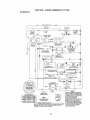
- Check wiring. See electrical wiring
diagram in the Repair Parts section.
TO REPLACE FUSE
Replace with 15 amp automotive-type
plug-in fuse, 'The fuse holder is located
behind the dash,
TO REMOVE HOOD AND GRILL
ASSEMBLY
o Raise hood.
, Unsnap headlight wire connector,
° Stand In front of tractor. Grasp hood at
sides, tilt toward engine and lift off of
tractor,
• To replace, reverse above procedure.
Seat
Battery
Door
Box
24
The carburetor has been preset at the
factory and adjustment should not be
necessary. However, minor adjustment
may be required to compensate for
differences in fuel, temperature, altitude
or toad, If the carburetor does need
adjustment, proceed as follows:
In general, turning the adjusting needtes
In (clockwise) decreases the supply of
fuel to the engine giving a leaner fuel/air
mixture, Turning tile adjusting needles
out (counterc!octqMse) increases the
supply of fuel to the engine giving a
richer fue!/air mixture.
IMPORTANT: Damage to the needles
and the seats in carburetor may result if
needle Is turned In too tight;
NOTE: The carburetOr on this engine Is
low emiSSion. It is equipped with an idle
fuel adjusting needle with a timiter cap,
which allows some adjustment wttl_ln
the llmlts allowed by the cap, Do not
attempt to remove the tlmiter cap. The
llmlter cap cannot be removed without
breaking the adjusting needle,
° Be sure you have a clean air filter and
the throttle control cable iS adjusted
properly (see above),
• Start engine and allow to warm for five
minutes, Make adjustments wf_h
engine running and shift/motion
control lever In neutral (N) position.
• _e #peed settln.g- With throttle
control lever in slow position, engine
should Idle at 1750 RPM, tf engine
Idles too slow or fast, turn idle speed
adjusting screw In or out unttl correct
idle is attained.
• Idle [uel needle sett!o_g- With throttle
control lever in slow position, turn Idle
fuel adjustment needle in (clockwise)
Maintenance, repair,
or replacement of
the emisslon control devices and
systems, which are being done at the
customers expense, may be performed
by any non-road engine repair establishment or individual, Warranty repairs must
be performed by an authorized engtne
manufacturer's service outlet,
ENGINE
TO ADJUST THRO'iq'LE CONTROL
CABLE
The throttle control has been preset at
the factory and adjustment sl_outd not be
necessary. Check adjustment as
described below before loosening cable,
If adjustment is necessary, proceed as
follows'.
o With engine not running, move throttle
control lever from slow to choke
posttlono Slowly move lever from
choke to fast position.
• Check to see If hole in throttle lever
and hole in speed controt bracket are
alfgned,
• If holes are not aligned, loosen cable
clamp screw and align the holes by
inserting a pencil or a 1/4" drill bit
through both holes.
• Pufl throttle cable up to remove slack
and tighten cable clamp screw.
Remove alignment pencil or drill btt,
TO ADJUST CARBURETOR
Cable
t
_t
Screw
Speed Control
Bracket
T
e
Lever
25
until engine begins to die and then
turn out (counterclockwlse) until
engine runs rough. Turn needle to a
point midway between tl3ose two
positions.
o Recheck idle speed. Readjust if
necessary.
ACCELERATION TEST, Move throttle control lever from stow to
fast position. If engine hesitates or
dles, turn Idle fuel adjusting needle
out (counterclockwise) 1/8 turn.
Repeat test and continue to adjust, if
necessary, until engine accelerates
smoothly.
High speed stop is factory adjusted. DO
not adjust - damage may result.
IMPORTANT: Never tamper with the
engine governor, which ts factory set for
proper engine speed. Overspeedtng the
engine above the factory high speed
setting can be dangerous, If you think the
englne.,governed high speed needs
adjusting, contact your nearest AUTHORIZED service center/department, which
has proper equipment and experience to
make any necessary adjustments.
Idle Speed
Adjusting
Screw
Idle Fuel
Adjusting
Needle
26
Immediately prepare your tractor for
storage at the end of the season or if the
tractor Will not be used for 30 days or
more.
_. CAUTION: Never store the tractor
with gasoline In the tank inside a
building wllere fumes may reach an
open flame or spark, Allow the engine to
cool before stonng in any enclosure.
TRACTOR
Remove mower from tractor for winter
storage. When mower is to be stored for
a period of time, clean it thoroughly,
remove all dirt, grease, leaves, etc, Store
in a clean, dry area,
• Clean entire tractor (See "CLEANING"
in the Maintenance section of this
manual).
, Inspect and replace belts, if necessary
(See belt replacement lnstructtons in
the Service and Adjustments section of
this manual),
• Lubricate as shown in the Maintenance section of this manual,
• Be sure that all nuts, bolts and screws
are securely fastened, fnepect moving
parts for damage, breakage and wear,
Replace if necessary.
o Touch up all rusted or chipped paint
surfaces; sand tightly before palntlng,
BATTERY
• Fully charge the battery for storage.
• After a period of time In storage,
battery may require recharging.
° To help prevent c0rroslon and power
leakage during tong periods of
storage, battery cables should be
disconnected aqd battery cleaned
thoroughly (see TO CLEAN BATTERY
AND TERMINALS" in the Maintenance
section of this manual).
° After cleaning, leave cables disconnected and place cables where they
cannot come in contact with battery
terminals,
• If battery is removed from tractor for
storage, do not store battery directly on
concrete or damp surfaces.
ENGINE
FUEL SYSTEM
IMPORTANT: It is important to prevent
gum deposits from forming in essential
fuel system parts such as carburetor, fuel
filter, fuel hose, or tank during storage.
Also experience lndtcates that alcohol
blended fuels 9called gasoho or using
ethanol or metl_anol) can attract moisture
which leads to separation and formation
of acids during storage. Acidic gas can
damage tile fuel system of an engine
while in storage,
, Drain the fuel tank.
, Start the englne and let it run until the
fuel lines and carburetor are empty.
* Never use engine or carburetor
cleaner products in the fuel tank or
permanent damage may occur,
, Use fresh fuel next season°
NOTE; Fuel stabilizer Is an acceptable
alternative In minimizing the formation of
fuel gum deposits during storage. Add
stabilizer to gasoline In fuel tank or
storage contalnero Always follow the mix
ratio found on stabilizer container, Run
engine at least 10 minutes after adding
stabilizer to allow the stabilizer to reacll
the carburetor. Do not drain the gas tank
and carburetor if using fuel stabilizer.
ENGINE OIL
Drain otl (with engine warm) and replace
with clean engine o11, (See "ENGINE" in
the Maintenance section of this manual),
CYLINDER(S)
. Remove spark plug(s),
o Pour one ounce of otEthrough spark
plug hole(s) Into cylinder(s).
, Turn Ignition key to "START" position
for a few seconds to distribute ott.
o Replace with new spark plug(s).
OTHER
, Do not store gasoline from one season
to another.
° ReplaCe your gasoline can If your can
starts to rust, Rust and/or dirt in your
gasoline wilt cause problems.
° If possible, store your tractor Indoors
and cover It to give protection from
dust and dirt,
, Cover your tractor wfth a Suitable
protective cover that does not retain
moisture. Do not use plastic. Plastic
cannot breatile which allows condensation to form and will cause your
tractor to rust.
IMPORTANT:
Never cover tractor while
engine and exhaust areas are still
warm.
27
TROUBLESHOOTING
CHART
PROBLEM
CAUSE
CORRECTION
,
Will not start
1, Out of fuel_
2, Engine not "CHOKED"
properly_
3, Engine flooded,
4,
5,
6,
7
8.
9,
I0,
Hard to start
6,
7_
8.
not
Engine clicks but
will not start
1, Clean/replace air filter,
2. Replace spark plug,
3. Recharge or replace
battery.
Dirty fuel filter.
4. Replace fuel filter
Stale or dirty fuel.
5, Drain fuel tank and refill
with fresh gasoline,
Loose or damaged wiring,
6, Check all wiring,
Carburetor out of adjustment, 7, See "To Adjust Carburetor"
In Service Adjustments
section.
8, Contact a Sears or other
Engine valves out of
adjustment,
qualified service center,
1. Dirty air filter°
2. Bad spark plug.
3, Weak or dead battery,
4,
5.
Enginewilt
turn over
I. Fill fuel tank,
2, See "TO START ENGINE"
in Operation section,
3, Wait several minutes
before attempting to start,
Bad spark plug,
4. Replace spark plug,
Dirty alr filter,
5, Clean/replace air fliter,
Dirty fuel filter.
6. Replace fuel filter.
Water In fuel,
7, Drain fuel tank and
carburetor, refill tarik wlth
fresh gasoline and replace
fuel filter,
Loose or damaged wiring.
& Check all wiring.
Carburetor out of adjustment. 9- See "To Adjust Carburetor"
in Service Adjustments
sectton
10,
Contact a Sears or other
Engine valves out of
adjustment,
qualified service center,
1. Clutch/brake
pedal not
depressed,
2_ Attachment clutch is
engaged.
3, Weak or dead battery,
2,
4.
5.
6,
7_
4.
5.
6.
7,
Blown fuse,
Corroded battery terminals.
Loose or damaged wiring.
Faulty ]gnltlon switch.
1, Depress
3.
8o Faulty solenoid or starter.
8,
9. Faulty operator presence
switch(as).
9.
t,
2.
3.
4_
Weak or dead battery,
Corroded battery terminals,
Loose or damaged wiring.
Faulty solenoid or starter,
28
_..
3,
4.
clutch/brake
pedal,
Disengage attachrnent
clutch.
Recharge or replace
battery,
Replace fuse.
Clean battery terminals.
Check al! wiring,
Check!replace ignition
switcl_.
Check/replace solenoid or
starter.
Contact a Sears or other
qualified service center,
Recharge
or replace
battery.
Clean battery
terminals.
Check all wiring.
Check/replace solenoid or
starter.
TROUBLESHOOTING
CHART
PROBLEM
CAUSE
CORRECTION
Loss
0fpower
.........
ill cuttiog
toomu ,h
grassltoo1. Setit,"H gher
Cut"positlon/
2_
3.
4.
5,
6.
fasL
Throttle in "CHOKE"
position.
Build-up of grass, leaves
and trash under mower,
Dirty air fittero
Low otl level/dfrty otl,
Faulty spark plug.
7. Dirty fuel filter,
8, State or dirty fuel,
reduce speed.
2, Adjust throttle control,
3, Clean
4,
5.
6,
'7,
8.
underside
of mower
housing,
Clean/replace
air filter.
Check oll level/change
otl.
Clean and regap or change
spark plug,
Replace fuel filter;
Draln fuel tank and refill with
fresh
' 10,Spark
plug wire loose.
11. Dirty engine air screen/fins,
12. Dirty/clogged muffler.
13.Loose or damaged wiring,
14.Carburetor out of
adjustment.
15. Engine valves out of
adjustment.
Excessive
vibration
1. Worn, bent or loose blade.
2, Bent blade mandrel
3. Loose/damaged part(s),
Engine continues
to run
when operator
leaves seat with
with attachment
clutch engaged
Poor cut - uneven
.
gasoline.
9, Drain fuel tank and carbure
F9. Water in fuel.
tor, refill tank with frestl
gasoline and replace fuel
filter.
t0,Connect
and tighten spark
plug wire.
11.Clean engine air screen/fin&
12.Clean/replace
muffler,
13.Check all wiring,
14 See "To Adjust Carburetor"
in Service Adjustments
section.
15,Contact a Sears or other
qualified service center,
1. Replace blade_
Tighten blade bolt.
Replace blade mandrel.
3. Tighten loose part(s).
Replace damaged parts.
2_
Check wiring, switches
and
connections,
If not
contact a Sears or other
qualified service center,
Faulty operator-safety
presence control system.
Worn, bent or loose blade.
2. Mower deck no1 level,
3, Buildup of grass, leaves,
and trash under mower,
4, Bent blade mandrel,
5. Clogged mower deck vent
holes from buildup of
grass, leaves, and trash
around mandrels.
29
1,
Replace blade, Tighten
blade bolt.
2, Level mower deck.
3, Clean underside
of mower
houslng.
, Clean
Replacearound
blade mandrels
mandrel, to
o
open vent holes,
TROUBLESHOOTING
PROBLEM
Mower blades will
not rotate
_ .
i uu ,JiL,
Poor grass
discharge
CHART
CORRECTION
CAUSE
1_ Obstruction in c{utch
mechanism.
2, Worn/damaged mower
drive belt,
3, Frozen idler pulley,
4, Frozen blade mandrel.
I,
Engine speed too slow.
2. ]ravel speed too fast,
3, Wet grass,
4. Mower deck not level,
5. Low/uneven tire air
pressure.
6. Worn, bent or loose blade,
7,, Bulldup of grass, leaves
and trash under mower,
8. Mower drive belt worn_
9. Blades improperly lnstal!ed.
10..Improper blades used.
11.Clogged mower deck vent
holes from buildup of grass,
leaves, and trash around
mandrels°
Headlight(s) not
working
If so equipped)
1.
2.
3,
4,
Swttch is "OFF".
Bulb(s) burned out.
Faulty light switch,
Loose or damaged widng.
5. B!own fuse.
1_ Remove obstruction,
2.
Replace
mower drive
be{t,
& Replace Idler pulley°
4. Replace blade mandrel.
1. Place tllrottle control in
"FAST" position,
2, Shift to slower speed,
3. Allow grass to dry before
mowing.
4. Level mower deck,
5. Check tires for proper air
pressure.
6. Replace/sharpen
blade,
Tighten blade bolt.
7, Clean underside of mower
housing.
9 [ Replace
Reinstall mower
blades drive
sharp belt.
edge
down,
10. Replace with blades listed
in this manual,
t 1 .Clean around mandrels to
open vent holes.
1,
2.
3,
4.
Turn switch "ON".
Replace bulb(s),
Checldrep!ace light switch.
Check wiring and conneo
tions.
5. Replace fuse,
i
!Battery will not
charge
1, Bad battery cell(s).
2. Poor cable connections,
3.
4.
Engine "backfires"
whenturning
engine "OFF"
Faulty regulator
(if so equipped),
Faulty alternator,
1,, Replace battery,
2. Check/clean all connec
tions.
3. Replace regulator..
4, Replace alternator.
Engine throttle control not
set at "SLOW" position
fo_ 30 seconds before
stopping engine,
3O
.
Move throttle control to
"SLOW" position and allow
to Idle for 30 se0onds before
stopping
engine,
TRACTOR - - MODEL NUMBER 917.271052
SCHEMATIC
l_.clJ£
...............
BATTERY
80LENOID
i
I
REMOVABLE
IGNITION SWITCH
cONNECT'ONS
_-_
NON.REMOVABLE
CONNECTIONS
RELAY
WIllING INSULATED OLIP_
NOTE: IFWIRING INSULATED CLIPS WERE REMOVED FOR
SERVICING OF UNIT, THEY SHQULD BE REPLACED TO
PROPERLY SECURE YOUR WIRING
31
WITH A SPECIAL ALTERNATOR
SYSTEM. 'THE UGHTS ARE NOT
CONNECTED TO THE BATTERY,
BUT HAVE THEIR OWN
ELECTRICAL SOURCE,
BECAUSE OFTH{S THE BRIGHTNESSOF THE LIGHTS W LL
CHANGE WITH ENGINE SPEED
AT IDLE THE LIGHTS WiLL DIM,
AS THE ENGINE IS SPEEDED UP,
THE LIGHTS WILLBECOME
THEIR BRIGHTEST.
TRACTOR--
MODEL
NUMBER
ELECTRICAL
32
917.271052
TRACTOR
-- MODEL NUMBER
917.271052
ELECTRICAL
KEY
NO,
1
2
PART
NO,
163485
74760412
DESCRIPTION
Battery
Bolt Hex Hd t14-20unc
8
16
21
22
24
25
26
27
28
29
30
33
40
4t
42
43
45
52
70
8t
'_56417
181343
166182
4t 52J
4789J
146147
166180
73510400
4207J
160784
163868
140403
170219
7t 110408
131563
145673
121433X
141840
170249
t09748X
Case Battery
Switch, Interlock
Harness Asm Light W/4152J
Bulb Light 4I 156
Cable Battery 6 Ge 11" red
Cabte Batter,] 6 Ga w/16 wlre red
Fuse15 AMP
Nut Keps Hex 1/4-20 Uric
Cable Ground 6 Ga 12" black
Swltch Plunger Normal Op Olive
Switch tgn
Key tgn
Harness Ign
Bolt Bltt. Fin Hex 1/4-20 Unc x 112
OoverTermlnal
Red
Solenoid
Ammeter Rectangular 6 Amp
Protection Wire Loop
Harness Engine
Re_ay Asm
x 3/4
NOTE; All component dimensions given In US, _nches
1 Inch --25-4 mm
33
TRACTOR - - MODEL NUMBER
CHASSIS AND ENCLOSURES
917.271052
29
53
31
_9
-3
60
II:Tz- "_.._.2'JA..Y
_
_'<t_7£B_:¢,_l_
_
1
5 _
2O8
34
TRACTOR
CHASSIS
-- MODEL NUMBER
917.271052
AND ENCLOSURES
KEY
NO_
t
3
5
9
10
11
12
13
17
18
25
26
28
29
30
31
37
38
51
52
53
54
55
57
58
60
64
74
t14
116
142
143
144
145
211
206
207
208
212
PART
NOr
DESCRIPTION
169830
169061
17060612
155272
168337X013
STD533710
155927
145660
172107X010
144983X558
t26938X
19131312
STD641437
156725X558
155217.',(599
164918X558
139976
17490508
169834
73800400
19091416
145201
161464
145202
STD522507
150127
72140606
154798
STD54t 437
158112
17060620
165867
154966
154207
156524
145212
170165
17670508
I7670608
165919
Chsasle
Dr_wbat
Screw 3/8q 6 x 3/4
BumperHood/Dash
Dash
edit, Carriage
3/8-16 x 3/4
Panet, Dash, L.H
Cflp Tlnnerman Gdlle P/L
Panel, Dash, R.H.
Hood Assembly
BumperHood
Washer
13/32 x 13/16 x 12 Gauge
Nul
Grille/Lens
Asm
Lens, Gdtle
FendiFtrest
Bracket, Fender Support
SorewThdro!
5/16-18 x 112
P_vot Bracket Assembly, Rear
Nut Look w/Insert 1/4-20 UNC
Washer
9/32 x 7/8 x 16 Ga
Bracket Grille Pickoff LH
Screw Hex Wshd 8-18 x 7/8
Bracket Gr]lte Plckoff RH
Bolt, Fin Hex 1/4-20 UNO x ,75
Duct Air Engine
BoltRdhdSqnk3/8-16UNC×3/4
DashLowerSTLT
Nut Orownleek 3/8016 UNO
KeeperBelt
RearLh StlP930
Screw 3/8-I6 X 1-1/4
PEateRetnforcementSTLT
Bracket Swaybar Chassis
Bracket Pnt Footrest STLT
Rod Pivot Chase]s/Hood
Nut Hex Flange Lock
Bolt Shoulder 5/16qBTT
Screw Thdro] 5/t6q8
x I/2 Tytt
Screw Thdro] 3/8-16 x 1/2
Insert Lens Reflective
--
5479J Plug0 Button
NOTE: Atl component dimensions given in U S, In_he_
I Inch = 2&4 mm
35
TRACTOR
- - MODEL NUMBER
917,271052
GROUND DRIVE
57
37
26
36
27
TRACTOR
-- MODEL
NUMBER
917.271052
GROUND DRIVE
KEY
NO+
PART
NO.
I
........
2
3
4
5
6
8
10
11
13
14
!6
!8
19
21
22
24
25
26
27
28
29
30
32
34
35
36
37
38
39
40
41
42
47
48
49
50
51
52
53
55
56
57
59
146682
123666X
12000028
121620X
17060512
185866
STD861210
105'701X
74550412
10040400
BTD541431
STD523710
STD54t4-37
!06933X
130804
STD54t237
106888X
STD5510,37
8TD561210
145204
71673
168592
STD523107
155071
t20183X
STD551062
STD571810
131494
$TD533727
4470J
165838
19131312
127783
154407
123205X
STD523715
STD5414.37
STD541431
105710X
105709X
STD523712
130801
168691
KEY
NO,
DESCRIPTION
Transaxle (See Breakdown)
Peedess206+545C
Spring, Re_urn, Bpake
PuJtey, Transa×le
Ring, Retainer
Strap, Torque
S_rew 5ll e-t 8 x 3/4
Rod Shtfter Fender STLT
Pin, Cotter
Washer, Shtft Plale
Bolt 1/4-28 UNF W/Patch Gr 8
Washer Lock Hvy Het_cai
Nut Lock Hx W/Ins 5116q8 x Gr.5
BoR Fin Hex 316-16uric x 1 Gr. 6
Nut
Knob
Red, Brake
Nut
Spring, Brake Rod
Washer
Pin
Rcd, Perk+ng Brake
Cap, Parking Brake
Bracket, Transexle
Bolt
Shaft Assembly,
Foot Pedal
Bearlng, Nyfon
Washer
Rolt Pin
Pulley, Idter, Flat
Boft
Spacer, Spilt.395
x 59
Keeper, Belt, Idler
Washer 13132x 13116 x 12Ga..
Pulley, idler, V-Groove, Plastic
Betlcrank Ctufeh Gad Dr,." SII
Retainer, Belt
Bo+t
Nut Crown Lock 3/8-16 UNC
Nut Qrown LockS/t6-18
UNO
Link, Clutch
Spdng, Clutch Return
Bolt Fin Hex 3/8-t6 x t+1/4
V-Bert, Ground Drive
Keeper, Belt, CenterBpan
PART
NO.
DESCRIPTION
Screw 3/8-16 x 3/4
Cover, Pedal
Pulley, Engine
Bolt, I..fex 7t16-20 x 4 Grade 5
Washer
61
62
63
64
65
66
70
72
74
75
76
77
76
79
80
61
82
83
84
85
89
90
96
112
t13
1t6
145
t 50
151
156
158
159
161
162
163
164
165
166
168
169
170
197
198
202
204
17060612
8883R
140186
71170'764
STD551143
154778
134663
19132012
137057
121749X
STD58tO75
123583X
121'748X
STD580025
145090
165592
165711
19171216
166231
150360
t5839tX428
124346X
STD624003
19091210
127288X
72110610
74490540
165880
19133210
166002
166589
165494
72140406
73680400
74780416
19091010
165623
166880
165492
165580
165849
169613
169593
72110612
17080516
NOTE:
AtEcomponent
dimensions
incllee 1 inch = 25 4 turn
37
Keeper, Belt, Engine, Fool Proof
Guide, Mower Drive Bait, R,]'-],
Washer 't3/32 x 1-1/4 x 12 Ga
Spacer, Axle
Washer 25/32 x 1 +1/4 x 16 Ga
E-Ring
Key, Square 2,O x .1845/1865
Washer
25/32 X 1-5/8 x 16 Ge
Key Woodruff
Arm, Sh+ft
Shant Asm Cross Tapered 650 20
Spring, Torsion
Washer
17/32 x 3/4 x 16 Ga+
Unk Transaxfe
Nu!, Nylcck
Console, Shift, STLT
Nut, Self-Thdlng,
Wsh Hd 1/4
Retainer Bpdng 1"
Washer
9132 x 3/4 x 10 Ga
Strap Torque 90 D agrees
Bolt Rdhd Sqneck 3/8+16 x ! .25
8o1!, Hex Flghd 5/18-18 Gr 5
Bushing Bellcrank Grd+ Drive
Washer
13/32 x 2 x t0 Ga+
Washer Srded 5/16JD x 1.125
Bracket Shift Mount
Hub Tapered Flange Sh+ft Lt
Bolt Rdhd Sqnk 1/4+20 x 3/4 Gr.5
Nu_ CrownIock
1/4+20 Unc
Bolt Flex Fin 1/4+20une x I Gr 5
Washer 5/8 x .281 x t0 Ga
Bracket Pivot Lever
Screw 5/16-18 x 5/8
Bo_t Shoulder 5/16+19 x +561
Plate Fastening LI
Kee#er Belt Transex_e Gear
NylinerSnap+ln
Washer Nyltner
Bolt Cart. SH 3/6+16 x t-1/2 Gr- 5
Screw 5/16+18 x t SMGML.
given In U. S.
TRACTOR
STEERING ASSEMBLY
/#+
\
-- MODEL NUMBER
'l
i:t!
3T.... _t
i
i
i
38
917.271052
TRACTOR
STEERING ASSEMBLY
-- MODEL NUMBER
KEY PART
NO. NO,
1
2
3
4
S
8
7
8
9
t0
ll
13
15
17
18
19
22
23
25
26
27
28
29
80
32
36
37
38
39
40
41
42
43
44
46
47
5t
54
62
63
65
66
67
68
79
60
82
85
139768
164427
189840
169839
6266H
121746X
18272016
12000029
3366R
169832
STD551137
136516
145212
156546
57079
160395
165857
165851
154406
128647X
138874
19131416
17060612
STD561210
130465
155099
162827
139769
19133812
STD541537
1007tlL
145054×428
121749X
153720
121232X
6855M
STD54!431
74780520
167902
STD523710
160367
154404
72140618
169829
19132012
74950612
169835
133835
917.271052
DESCRIPTION
Steering Wheel
Axle Aesembty STMP Dropped STL
Spindle Assembly, LH,
Spindle Assembly, R,H.
Bearing, Race, Thrust, Hardened
Wa_her 25/32 × 1-5/8 x t6 GaUge
Washer 27/32 × t-1/4 × 16 Gauge
Ring, Kltp
Bearing, Steering Column
Dragtfak
Washer, Lock
Spacer Bearing Axle Front
Nut, He× Flange Lock
Shaft Assembly, Steering
Washer, Thrust .515 x .760 x 033
Support, Shaft
Screw, Hex Wsh Hd Torx
Plttman Shaft Assembly
Brackel, Steedng
Bushing, Link, Drag
Gear, Sector
Washer 13/32 x 7/8 x !6 Gauge
Screw 3/8-I 6 x 3/4
Pin Colter
Rod, Tie
Bush{ng, Steering
Screw
{nsert, Steering Whee_
Washer 13/32 x 2-3/8 x 12 Gauge
NL_tLock Center 3/8-24 Unf
Adaptor, Steering Wheel
Boot, Steedng Shaft
Washer 25/32 x 1-1/4 x 16 Gauge
Extension Shaft Steering LR-LT
Cap, Spindle
Fitting, Grease
Nut Lock Hex w/ins 5/t6-18 UNC
Belt Fin Hex 5/t 6-18 UNC x 1-1/4
Kit Steering Asm Serv{ee
Bolt, Ftn Hex 3/8-18 UNC x 1 Gr 5
Spacer Brace Axle
Bearing Arm Ptttman
So{t ROHD Sqnk 3/8-16 x 2-1/4
Axle, Brace
Washer 13/32 x t-1/4 x 12 Go.
Bolt Hex Nylon 3/8-16 x 3/4
Bracket Susp Chassis Front
Fastener ChdstmasTree
NOTE; All component dimensions given In U,S, Inches
1 Inch = 25,4 mm
39
TRACTOR
- - MODEL
NUMBER
917.271052
ENGINE
60_..
33
29
OPTIONAL
EQUIPMENT
Spark AtteSter
KEY PART
NO, NO,
I
2
162156
17720410
3
......
4
13
14
15
16
23
29
31
32
159420
124341433
13200328
13200300
STD551237
169837
137180
109202X
158990
DESCRIPTION
Control,rhrottie
Screw, Hex Head, Thread
Culting 1/4-20 x 5/8
Engine, (See _reakdown)
KohlerMOde] CV15-4_ _;92
Mutf_er
Gasket
Nipple, Pipe 3/8 NPTx 3-1t2
Elbow_ Standard 90°, 3/8-18 NPT
Washer
SNeld Brn/Dbr Guard
Arrestor, Spark
Tank, Fuel
Cap Assembly, Fuel Seers, Vented
KEY PART
NO. NO.
33
123487X
,37
137040
38
40
44-
124028X
17490412
45
46
77
80
B1
101
105
17000612
19091416
19101216
7476O5O8
7351040o
M7303080o
17120616
DESCRIPTION
Clamp, Hose
Line, Fuel
Plug, O1fDrain [See Engine
Breakdown)
Bt;,shlng, Snap, Fuel Ltne
Screw, Hex Washer Head,
Thd, RotL 1t4-20 × 3!4
Screw Hxwsh Thdr 3/8-16 x 314
Washer 9t32 x 7/8 x 16 Ga
Washer 5/16 x 3f4 × 16 Ga,
Bolt Hex Hd 5/16-t8 Unc x I/2
Nut Keps Hex I14-20 Unc
Nut Flange M8-1,25 Non-LkZinc
Screw 31B-16x I
NOTE: All component dimensions given tn U.& inches
1 Inch = 25,4 mm
4O
TRACTOR
-- MODEL NUMBER
917.271052
SEAT ASSEMBLY
KEY PART
NO. NO.
1
2
3
4.
6
6
7
8
9
!0
!1
12
140122
140551
71110616
19131610
145006
STD5,_1437
124181X
17000616
19131614
155925
166369
121246X
KEY
NO,
DESCRIPTION
Seat 3350 B_k/bfk Craftsman
Bracket Pnt Pivot Seat (b_k }
Bolt Fin Hex 3/8-16unc X 1
Washer 13/32 X 3f4,X 10 Ga
CIlp Push in Hinged
Nut He× Look wtfns 3/8-16 Unc
Spring Seat Cprsn 2 250 Blk Zt
Screw 316-16 X 1
Washer !3/32 X 1 X 14 Ga
Pan Pnt Seat (blk)
Knob Seat AdJ Wingnut
Bracket Pnt Mounting Switch
13
14
15
16
'_7
21
22
24
25
PART
NO.
121248X
720604,12
134300
12!25OX
123976X
171852
STD54t431
19171912
127018X
DESCRIPTION
Bushing Snap Btk Nyi 50 ld
Bott Rdhd Sht Nk t/4_20xt-tt2
Spacer Split 28 X 96 Zinc
Spring Cprsn 1 27 BIk Pnt
Nut Look 1/4 Lge Fig Gr 5 Ztnc
Boft Shoulder 5tl 6-18 Unc-2A
Nut Hex Lock w/Ins 5/164 8
Washer 17/32 X 1,-3/I6 X12Ga,
Boft Shoulder 5tt 6-18 X 62
NOTE: All component dimensions given in U S Inches
1 Inch = 264 mm
41
TRACTOR
-- MODEL NUMBER
917.27t052
DECALS
13
6
3
4-
2
I3
li
2O
12
KEY PART
NO. NO.
DESCRIPTION
KEY
NO,
PART
NO,
DESCRIPTION
1
2
3
4
5
6
7
6
9
10
Decal, Opel lnstr.
Decal, Replacement
Decal Hood, R H..
Der._, Hood, LH
Oecat, Battery
D ecat, Customer Maintenance
Decal, HP Engine
Decal, Deck Mower EZ
Decal, Fender, Craltsman
Decal, Fender Danger
12
13
14
20
21
-..
- - - -
148046
16326'1
160396
149516
163207
138311
16.5800X426
165799X428
174392
174393
Decal, V-Belt Drive Schematic
Decat, Dash Panel
Decal, V-Belt Schematic
Decai Battery DngrlPsn Eng
Decal, Fender Sd, Wht
Decat, Lift HandIe
Pad Footrest LH STLT
Pad Footrest RH STLT
Owners Manual, English
Owner's Manual, Spanish
156368
17t762
171699
171699
136047
133644
169427
166887
163204
156439
WHEELS
& TIRES
KEY
NO,
1
2
3
4
5
6
7
8
9
10
tt
*-
4JO
PART
NO,
59192
65139
106222X
59904
!06732X427
27BH
9040H
106108X427
122082X
7152J
104757X
_44.._4
DESCRIPTION
Cap Value Tire
StemVelue
T|re F Ts 15 X 6 0 - 6 Service
Tube Inner Front _135060
Rim Asm 6"front White Service
Fitting Grease
Bearing FIange
Rim Asm 8"rear Wrtlte Service
Tire i_ Te 20 X t0.,6 Service
Tube Rear 9 5 X 8 Service
Cap Axle Blk 1 50 X 1 00
Seelanf, Tire (10 oz tube)
NO'f Et All component dimensions given in U3. Inches
f Inch = 25,4 mm
42
TRACTOR
--MODEL
NUMBER
917.271052
LIFTASSEMBLY
R
i/
!
t
!
!
J
i
3
13
2
t3
19
2O
13
19
KEY PART
NO, NO,
1
W/Plunger
2
3
4
5
6
7
B
tl
12
13
t5
16
17
18
19
20
3t
NOTE_32
DESCRIPTION
169460
Washer
Asm Inner Spring
159471
105767X
12000002
10211621
120183X
125631X
122386X
138865
139868
STD624008
173288
73350800
130171
73800800
Shall Asm Lift
Pin Groove
E Ring #5133-62
Washer 21/32 x 1 x 21 Ga.
Bearing Nyiorig
Grip Handle Ftuted
Bufton Plunger Read
Link Aem Lift LH
Link Asm Lift R,H
Retainer Spring
Link Front
Nut Jam Hex 1/2-t3 Uric
Trunnion BIk Zinc
Nul Loci( w/Wsh 1/2-13 Unc
139868
163552
140302
Arm Suspension Mower
Retainer Spring
Bearing, PvL LIlt, Spherical
7,
40 0
ow £c_}ven'_4U
3/8
_c4o_onentNd_i_%,_ls
S inches
1 Inch =25 4 mm
43
TRACTOR
MOWER
-- MODEL NUMBER
917.271052
DECK
34
.112
44
TRACTOR
MOWER
-- MODEL
NUMBER
917,271052
DECK
KEY PART
NO, NO°
1
2
3
165892
STD533107
1380t7
4
5
6
5
9
10
11
12
I3
165460
STO624008
130632
650657
S_'D551137
140296
134149
129895
137645
14
15
t6
18
19
26
21
22
23
24
25
28
27
26
29
30
3t
32
33
34
35
36
37
4O
44
45
46
48
49
50
51
52
53
54
55
86
59
67
68
128774
110485X
140329
72140505
132827
159770
STD5414OI
134763
131267
105304X
123713X
110452X
130968X428
19111O16
131491
157722
129963
153535
137266.
STD533717
133835
131494
STD55tO37
STD541437
140088
STD524003
137729
133944
155066
131340
STD541410
139888
131845
133943
155046
165723
141043
149845
144959
KEY PART
NO. NO.
DESCRIPTION
Mower
Bell
Deck Assembly,
42"
DESCRIPTION
Nut
Mu}oherCover
Screw
Washer #10
Washer, Lock
Latch Assembly, Bagger
Nut, Weld
Bracket Gauge Whee_ Lh
Bracket GaUge Wheel Rh
Screw 5/16-18 x 3t4
92
10I
STD541437
136420
Bracket Assembly,Sway
Bar,
Front
Bracket Sway Bar 38/42" Deck
RetalnerSprtng
Arm, Suspension, Rear
Bolt, He× a18-24 x 1.25 Gro 8
Washer, Lock
Washer, Hardened
Blade, Mulching
Beadng, Ball
Shaft Assembly,
Mandrel, Venled
(fncludes Key Number12)
Houstng, Mandret, Venled
Bearing, Ball, Mandrel
Stripper, Vented Mower Deck
Bolt, Carrtage
5116-18 x 518
Bolt, Shoulder
Baffle, Vortex
Nut Crowntock 5116-18 UNC
Stiffener' Bracket
Bracket, Oeflecter
Cap, Sleeve
Spring, Torsion, Deflector
Nut, Push
Shleld, Deflector
Washer
11/32 x 518 x t6 Ga.
Rod.Hinge
£erew Thdrol Washer Head
102
103
104
105
106
1II
112
113
114
1!5
116
117
t18
119
121
128
t29
130
131
142
143
144
145
146
147
148
149
150
71161010
19061216
STD551110
160793
2029J
155197
I5.5198
17060512
73510500
72110504
4898H
165746
73930600
19121414
!43723
153390
19131312
STD523710
STD5337tO
165690
157109
158634
165888
165691
131335
I69022
165898
19091216
Washer, Spacer
Puiley, Mandrel
Nut, Toplock, Flanged
SoFt
Fastner, Christmas Tree
Pulley, tdlar, Flat
Washer
13132x 13t16x16Ga.
Nut Crownlock3/8-16
UNO
Guard, Mandrel, LH.
Retainer
Screw, Thd. Roll 1t4-20 x 5/8
Washer, Hardened
RoIler Assembly, Cam Follows r
Bolt, Shoulder
#10-24 Grade 5
Lecknut
Bolt, Shbulder
5/16-18 UNO
Arm Assembly,
Pad, Brake
Washer, HardenEd
Arm, Idler
Spacer, Retalnsr
Guard, TUV Id!sr
Knob Custom Ovef
V-Belt
151
152
t53
154
t55
156
157
I58
159
-*
169670
169676
169674
169675
16967t
169672
169869
17720410
72140614
130794
- -
169583
NOTE;
All component dimensions
Inches1 Inch =25.4 mm
45
Nut Keps 5116-18 Unc
Bolt Carr 5/16-Unc × 1/2
Bolt Shoulder
Wheel Gauge Std
Nut Centetlock 3t8-I 6 Unc
Washer 3t8 x 7/8 x 4 Ga.
Bracket Extruded Gauge Wheel
Washer Felt
Washer 13/32 x 13/16 x 12Ga.
Boil, Fin Hex 3/8-16 UNC x I Gr. 5
Bolt, Rdhd Sqnk 3/8q 6UNC xl
Ann Spring Brake Mower
Bracket Arm Idler 42"
Keeper Bell 42" Clutch Cable
Pul{ey ldter Fiat
Boll Carriage Idler
Spring Exlens_on
Spdng Return Idler
Retainer Spring Yellow Zinc
Washer
9/32 x 3/4 x 18 Ga.
Bracket Clutch
Cable Clutch 42 In
Wasller Flat 3/8" Type B
Spring Retainer
Spring Retention Lever
Spacer
Rod C_utch
Screw Hex Thd Cul 1/4-20 x 5/8
Bolt Rdhd Sqn 3/8-I 6 Unc x 314
Mandret Assembly (Inclddes Key
Numbers
8-10, 12-15, 31 and 32)
Mower Deck, Comptete (Standard
Deck, Order Separately
Mulchsr
Ptale and Gauge Wheel
Components,
Key Nes. tO1-t06
and111-12!)
given In U S.
TRACTOR
PEERLESS TRANSAXLE
- - MODEL
NUMBER
917.271052
- - MODEL NUMBER 206-545C
35A
46
TRACTOR
-- MODEL NUMBER
917.271052
PEERLESS TRANSAXLE - - MODEL NUMBER 206-545C
REF
NO.
PART
NO,
1
2
3
4
5
5
6A
7
8
8A
9
10
t1
12
13
772147
780086A
770128
776395
776409
778364
776369
778330
792180
792047
784352
784378
778334
778309
778368
14
779368
15
17
18
20
21
22
28
25A
26
27
28
29
29A
298
280
30
31
778370
786188
786102
792077A
792078
792079
792073A
7921 Z7
792125
792035
768040
780072
780160
780051
760199
780108
780001
31A
32
34
35
35A
36
37
38
39
40
780195
788083
780194
780193
780197
790075
790007
798021
786026
792076A
REF
NO,
PART
NO,
41A
42
42A
43
44
45
46
47
48
49
58
51
52
53
54
66
57
58
58
60
61
65
66
67
69
70
7I
71B
76
77
79
92
83
85
87
150
187
t80
900
790079
792073A
792085A
792075
790025
"766066
786088
774690
774691
778356
778338
778354
778352
778350
778346
778355
778387
778353
778351
778349
778345
760169
776422
776396
792170
796187
786069
786092
780090
788078A
792144
778333
778338
792154
788089A
788093A
788088A
730229A
794712
DESCRIPTION
TransaxieOover
Needle Bearing 8t8"
Transax_e Case
Countershaft
Output Shaft
spur Gear (38 teelh)
Spur Gear (15 teelh)
Spur Gear (1 t teeth)
Shill Key
Woodruff Key #9
Shift Ootlar
Shirt Rod & Fork
Bevel Gear (80 teeth)
Input Bevel Pinion (!3 teeth)
Bevel Gear (13 teeth)
(include, 14)
Bevel Pinion (13 teeth)
(tnalude. 13)
Ring G ear (43 teeth)
Drtve Pin
Spacer 1.130 X ,695
Bali 8116" die
Set Screw 3/8 - 10 x 3/6"
Sprtng _310 OD x ,,625 L
Screw !/4 - 20 x 1-ti4"
Screw 1/4-20 x l-3/6"
Retaining Ring (pkg of 2)
Retaining Rtng
RetafntngRtng
Thrust Washer .627 tD xO31W
Thrusl Washer 762 ID x.O31W
Thrust Washer,762
IDx.O31W
AntbRotattonWasher.632
Cup Washer 1.127 ID x ,032W
Fiat Washer .750 ID x O56W
(UseAsNeeded)
Fiat Washer.750
ID x,06fiW
Oii Seal 8f8"
Bushing .563
Flanged Bushing 5 / 8" ID
FiangedBushfng
751
Brake Disk
Brake Pad Plate
Brake Pad (pkg el 2)
Dowel Pin
Flat Washer ,312 ID x ,059W
DESCRIPTION
Brake Lever
Screw 1/4 - 20 x lq/4"
Screw 1/4 ,-20 x 2 1/4"
Locknut 5 / 16 --24
Brake PaU Holder
Spacer .2625 x 1,0
Brake Lever Bracket
Axis (11-I5/16'
Long)
Axle (16 - 1 l 2" long)
Spur Gear (29 leeth)
Spur Gear (27 teeth)
Spur Gear [23 teeth)
Spur Gear (t9 teeth)
Spur Gear (t6 teeth)
Spur Gear (t5 teeth)
Spur Gear (11 teeth)
Spur Gear (13 teeth)
Spur Gear (t7 teeth)
Spur Gear (2t teeth)
Spur Gear (24 teeth)
Spur Gear (25 teeth)
Fiat Waahe_" 583 fD x .O62W
Input Shalt
Shifter & Brake Shaft
Retaining Ring
Spacer .890
Square Cut Ring
"O" Ring
FIat Washer t. 128 ID x 058W
Inverted Retaining Ring
Spdng .430 OD x .5000 L
Bevel & Spur Gear (30 & 13 1seth)
Spur Gear (27 teelh)
0tl Fill Plug
Oil Seal 9/16"
Liquid Gasket RTV Silicone
OII Seal 3/4"
Gear Oil 8OW90
Replacement, MS] o208-545C
Transax/e
NOTE; Aft component dimensions given {nU S
Inches1 Inch = 25,4 mm
47
TRACTOR -- MODEL NUMBER 917.271052
KOHLER ENGINE-MODEL NUMBER OV15S, TYPE NUMBER 41592
BLOWER
HOUSING
AND
BAFFLES
t
_4
15
_g
_LLLL
EXHAUST
_o4
!
4
/
6
48
TRACTOR -- MODEL NUMBER 917.271052
KOHLER ENGINE-MODEL NUMBER CV15S, TYPE NUMBER 41592
ENGINE
AIR INTAKE
KEY
NO.
1
PART
NO.
12-743-05
2
3
4
5
6
7
25-341-02
12"°096"24
12-083- 08
12-t00-01
X-25-63
t 2-083-05
t2-3t3-04
12-094-12
10
12-072-05
11
12-086-0t
12
12-041-02
DESCRIPTION
Kit, Air Cleaner
(includes Key Numbers 2
thru 12)
Knob, Air Cleaner Cover
Covet, Air Cleaner
Precleaner Element
Wing Nut
Washer, Plain 1/4
Elernent, Air Cleaner
(Includes #7)
Grommet
Base, Air Cleaner
(includes Key Numbers g
and 10)
Stud, Mounting Plate M6 x
10x
66
Screw, #10 Hi-Lo Thread
Forming (2}
Gasket, Air Cleaner
NOT ILLUSTRATED
•12-113-63
Decal, Air Cleaner
CRANKSHAFT
KEY
NO.
t
2
PART
NO,
12-014-37
12-139-0t
BLOWER HOUSING
KEY
NO.
1
PART
NO.
M-0545010
2
3
4
24-468-10
12-146-07
M-0645020
6
7
8
9
10
11
24-096-06
12-027-32
12-096-28
12-t41-01
25-t54-02
M-0545020
!2
13
12_063-05
M-0645016
14
15
t2-063-08
12-063-0t
DESCRIPTION
Crankshaft
Plug, Cup
AND BAFFLES
DESCRIPTION
Screw, He:< Flange
M5 x 0.8 x 10 (8)
Washer, Plain 1/4
Plate, Blower Housing
Screw, Hex Flange M6 x 1,0
x 20
Cover, Pinion
Houslng, Blower
Cover
Ring, Retafner (2)
Clip, Mounting (3)
Screw, Hex Flange M5 x ,8
x 20 (3)
Baffle, Intake Side
Screw, Hex Flange
M6x 1Ox 16 (2)
Baffle, Cylinder Head
Baffle, Cylinder
NOT ILLUS3"RA3rED
-t2-!13-64
Decal,
CONTROLS
KEY
NO.
1
2
3
PART
NO,
12_079-07
12-237-01
M..0664020
4
5
M-0545016
12_536-09
6
7
M-0443020
SM-0443025
8
g
10
1t
12
!2-089-11
12-089-23
12-089-24
M-0641060
SM-0642025
13
14
15
16
12-090-08
25,,158ql
t2-079-0t
25-158-08
DESCRIPTION
Linkage, Cl]oke
Clamp, Cable
Screw, Locked Socket
M6 x 1.0 x 20 (2)
Screw, Hex Flange M5x.8x16
Control, Speed Assembly
(Includes Key Numbers 6
through 9)
Screw, Pan Head M4xO,Tx20
Screw, Pan Head M4x07
x 25
Spring, Choke Ad}ust (2)
Spring, Choke Return
Spring, Governor
Nut, He× Flange M6 x 1.0
Screw, Hex Flange
M6 x t-0 x 25
Lever, Governor
Bushing, Throttle Linkage
Unkage, Throttle
Bushing, Linkage Retaining
EXHAUST
KEY
NO.
1
2
3
4
5
6
PART
NO,
M_0829033
12-041-03
M-0841080
12-126-11
12_445-06
M-0645025
DESCRIPTION
Gtlld, M8 X 1,25 x 33 (2)
Gasket, Exhaust Manifold
Nut, Hex Flange M8 x 1.25 (2)
Bracket, Muffler
Strap, Lifting
Screw, Hex Flange
M6x 1_0x25(2)
NOTtt.LUSTRATED
KEY PAn
NO.
---
NO.
12-522-18
12o.755-59
RPM Settings:
RPM Settings;
NOTE:
Horsepower
49
DESCRIPTION
Short Block
Gasket Set
Low Speed; 1500-2000
High Speed: 3200-3400
All component dimensions
inches 1 Inch = 25.4 mm
given in U.S.
TRACTOR -- MODEL NUMBER 917.271052
KOHLER ENGINE-MODEL NUMBER CV15S, TYPE NUMBER 41592
FUEL
SYSTEM
J
<Io 2,_.Y
_t4
2
/
33
r
3t
CYLINDER
HEAD,
VALVE
AND
BREATHER
]"
25__
17
14
t
15
5O
I
30
23
TRACTOR -- MODEL NUMBER 917.271052
KOHLER ENGINE-MODEL
NUMBER CV15S, TYPE NUMBER 41592
FUEL SYSTEM
KEY
NO.
1
PART"
NO.
12_853_56
2
3
12-04t-02
12-053.56
4
5
6
7
8
9
10
1t
12
t3
I4
15
16
t7
t8
t 9
20
12..041-01
12-089-23
12-079-07
12-265-04
X-426-9
25o353-10
25-050,02
47-t54-01
12-086-07
12.431-01
12.-368-05
12-089-09
12-086_04
12-089-09
12-148-03
25-O86-27
12-i44-0g
2t
22
23
24
25
26
27
28
12-144-08
12-089-10
t2-146-02
12-337-03
12W57-02
12-041-05
12-104_01
12-757-09
29
30
12-041-06
M-0641060
31
32
33
X-25-63
X-22-11
M-0629122
CYLINDER
DESCRIPTION
Kit, Carburetor (Includes #2
thru 6)
Gasket, Air Cteaner
Carburetor Assembly
(For Information Only - Net
Available Separately)
(includes Key Numbers t2
thru 27)
Gasket, Carburetor (2)
Spring, Choke Return
Linkage, Choke
Deflector, Heat
Clamp, Hose (2)
Line, Fuel, 9"
Filter, Fuel
Clip, Cable
Screw, Hex Cap 8-32 x 3/8
Sleeve, insulating
Needle, Idle, Fuel Adjust
Spring, Idle Fuel
Screw, Idle Speed Adjust
Spring, Idle Speed
Plate, Throttle
Screw, Throttle Plate (2)
Shaft, Throttle wlth Lever
and Seal
Shaft, Choke
Spring, Choke
Plate, Choke
Jet, Main
Kit, Float
Gasket_ Bowl
Bow!, Fuel
Kit, Solenoid Assembly
(includes Key Number 29)
Gasket, Bowl Retainer Screw
Nut, Hex Flange M6 x 10
KEY
NO.
1
2
3
4
5
6
(2)
NOT ILLUSTRATED
-12-041-01
Gasket, Carburetor
*12-757-03
Kit, Carburetor Repair
-12.518-05
Lead, Solenoid, Black, 5",
14 Gauge, Uninsulaled
Push-On Tabs
_41-518-34
Lead, Ground, Green, 5% 18
Gauge Insulated Grip Barref
Eyelets
-277563
Connector
**
12-454-03
Tie, Cable
51
PART
NO.
12.35t .01
12-755-60
12-411-01
12-041 - 10
12.017-0t
12-017-02
12-016°01
t 2-0t 6-02
7
8
9
t2-146-13
12-468-06
12-t12-!3
10
12-086..15
11
12
13
t4
15
16
12-08g-01
12-173-01
12W55-03
X-426-9
12_326-03
M-0645020
17
18
19
20
12-0g6-07
235011
24-632-05
M-0640034
21
22
23
24-194-01
24-186-03
M-0545010
24
25
26
27
12-018-01
12-402-02
12-318-09
X-75-23
NOTE=
Washer, Plain 1/4
Washer, Lock 1/4
Stud, M6 x 1.0 x 122 (2)
HEAD, VALVE AND BREATHER
DESCRIPTION
Lifter, Valve (2)
Kit, Cylinder Head
Rod, Push (2)
Gasket, Cylinder Head
Valve, intake, Sta¢_dard Size
Valve, Intake, .25" Oversize
Valve, Exhaust, Standard
Valve, Exhaust, 25"
Oversize
Plate, Guide
Washer, Plain t3/32
Spacer, Head Belt Exhaust
Port
Screw, Hex Flange
Mt0 x t.5 x 81 (5)
Spring, VaIve (2)
Cap, Valve Spring (2)
Kit, Retainer (2)
Clamp, Hose (2)
Hose, Breather
Screw, Hex Flange
M8 x 1.0 x 20 (5)
Cover, Valve with Nipple
Retainer, Spring
Seal, Valve Stem
Screw, Hex Flange M6 x t x
34 (2)
Pivot, Rocker Arm (2)
Arm, Rocker (2)
Screw, Hex Flange
M5 x 0.8 x t0
Retainer, Breather Reed
Reed, Breather
Head, Cylinder
Plug, Pipe, Allen Head 1/8
All component dimensions
inches
1 Inch = 25,4 mm
given in US,
TRACTOR--MODEL
NUMBER 917.271052
KOHLER ENGINE-MODEL NUMBER CV15S, TYPE NUMBER 41592
i,l,,
OIL
PAN
/ LUBRICATION
0
3
@
@
52
J
TRACTOR -- MODEL NUMBER 917,271052
KOHLER ENGINE-MODEL NUMBER CVISS, TYPE NUMBER 41592
IGNITION
/ ELECTRICAL
KEY
NOo
1
PART
NO.
12-086-14
2
12,,468-03
3
4
24_162..03
M-0639016
5
6
7
8
9
I0
12-lt2.01
12-167.-02
X-42-t5
t2-026-37
12-155-02
M_0548025
11
M.0545010
12
13
14
15
16
17
12-t54-02
12-085-08
12-132-02
X-728-1
12-584-01
M-0545020
CRANKCASE
DESCRIPTION
Screw, Hex Flange
Mr0 x 1 5 x 46
Washer, Plain 3/8
Screen, Grass
Screw, Hex Flange M6 x t x
16 (4)
Spacer, Fan (4)
Fan
Key
FLywheel Assembly
Connector (4 Contact)
Screw, Hex Cap
M5 x 08 x 28 (2)
Screw, Hex Flange
M5 x 0,8 x 10 (2)
Cllp, Stator Harness
Stator Assembly
Spark Plug
Clip, Cable
Module, Ignition
Screw, He× Flange
M5 x 08 x 20 (2)
KEY
NO.
PART'
NO,
1
2
12-032-03
12-522-18
3
12-445-02
4
5
6
M-0839025
12-380-03
12-755-49
7
8
12-089-18
12-422-08
12-144-27
12-874-07
12-874-08
12-874-09
NOT ILLUSTRATED
-12-518ql
Lead, White, Ground 'To Kilt
(19", 18 Gauge, Futly
Insulated Push-on 'Tab and
Uninsulated
Push-on "f_b
Terminals)
! 1
t2
12-018.02
12-108-07
12-108-08
13
12-108-09
12-067-05
12.067- 06
OIL PAN t LUBRICAI"]ON
14
15
16
t7
18
|9
12-380-01
t2-043-05
M-0631005
12-144-02
52-13g-09
I2-755-64
20
12-144-24
2f
22
23
24
X-25-!02
12-032-01
8M-O631015
t2-154-.05
PART
NO.
12=038-0!
2
28-755-13
3
4
5
6
12-453-03
t2-153-02
12-123-04
M-O545020
7
8
g
10
12-153-01
25-162-07
12-096-03
M-0545016
tt
M-1039025
12
12-126-02
13
14
15
t8
t7
t8
t9
20
21
12-089-03
12-462-01
12.208-01
12-050-01
X-75-t0
12-393-01
12-032-04
12-096-02
M-0545016
22
23
12-032-03
SM-0839045
24
t2-19g-30
pnng; Actuating
Shim, Camshaft, Blue
Shim, Camshaft, Red (A.R.)
Shim, Camshaft, Yellow (A,R)
Shim, Camshaft, Green (A.R,)
Shim, Camshaft, Grey (A.R.)
Shlm, Camsbalt, Black (A.R)
Shim, Camshalt, White (A.R)
Shaft, Balance
Piston w/Ring Set, Standard
Piston w!Ring Set .25"
Oversize
Piston w/Ring Set 50"
Oversize
Retainer, Piston Pin (2)
Ring Set, Standard
Ring Set .25" Oversize
Ring Set .50" Oversize
Connecting
Rod, Standard
Connecting Rod 25"
Oversize
Pin, Governor Regulating
Gear, Governor Assembly
Washer, Plain, 6ram
Shaft, Governor Gear
Plug, Cup
Kit, Shaft, Governor Cross,
with Clip (includes Key #20
and 24)
Shaft, Governor Cross
Washer, Plain t/4
Seal, Governor Cross Shaft
Washer, Plain, 6mm
Clip, Hitch Pin
12-422-0g
I2-422-10
12-422-tl
12-422-12
12-422-13
12-422-07
9
10
KEY
NO,
1
DESCRIPTION
Seal, Crankshaft
Block, Cylinder (Use Short
Block)
Strap, Lifting
Screw, Hex Flange M8 x
1.25 x 25
Dowel, Locating (4)
Kit, Canlshaft (includes Key
DESCRIPTION
Dipstick Assembly
(Includes Key Numbers 2 and
3)
Kit, Oil Fi!} Cap (Includes Key
#3)
O-Ring, Dipstick
O-Ring, Upper Oil Fill Tube
Tube, OI! Filt
Screw, Hex F_ange M5 x 0,8
x 20
O-Ring, Lower Oil Ftil Tube
Screen, Oil Pick-up
Cover, Oit Pick.up Screen
Screw, He× Flange M5 x 0..8 x
STARTING
16
Screw, Hex FIange M10 x 1.5
x 25
Bracket, Oil Pump Relief
Valve
Spring, Oil Pump Relief Valve
Piston, Oil Pump Relief Valve
Body_ Oil Pump Relief Valve
Filter, Oil
Plug, Square Head, Solid 3/8
O1t Pump Assembly
O-Ring, Otl Pump Cover
Cover, OII Pump
Screw, Hex Flange
M5 x 0,8 x 16 (3)
Seal, Oil (PT, O End)
Screw, Hex Flange
M8x 1,25 x 45 (12)
Pan, Oil
KEY
NO.
1
PAR]'
NO.
M-0839070
2
25.,098-03
3
4
5
12-755-54
12-227_06
45-'E70-03
7
8
12.227-11
12-086-25
NOTE:
53
SYSTEM
DESCRIPTION
Screw, Hex Flange
M8x 125x 10(2)
Starter Assembly
(includes Key Numbers 3 thru
8)
Kit, Drive End
Cap, Drive End
Armature
End Cap, Commutator
Screw, Hex Ffange
1/4-20 x 4-518 (2)
All component dimensions given in U.S
inches 1 inch = 25 4 mm
54
SUGGESTED
GUIDE FOR SIGHTING
SIGHTING
GUIDE
SLOPES
FOR SAFE OPERATION
ONLY RIDE UP AND DOWN HILL,
NOT ACROSS HILL
SIGHT AND HOLD THIS LEVEL WITH
SKY LINE OR TREE.
•_ _
_! ,ilt_j_.
al _
_!
Operate your T_ctor up and down the face of slopes (not
greater than 15 _, never across the face. Make turns gradually to prevent tipping or loss of control. Exercise extreme
caution when changing direction on slopes.
Your
For repair -- in your home
lawn and garden
equipment,
no matter
who made
For the replacement
owner's
manuals
that
For Sears
and items
professional
Itke garage
Home
- of all major brand appliances,
or heating and cooling
systems,
it, no matter
who sold it!
parts, accessorfes
and
you need to doqt-yourself.
installation
door openers
1-800-4-MY.-HOM
E@
(1-800-469-4663)
www.seare,com
Anytime,
day or night
(U.SoA, and Canada)
www.aears,ca
Our
For repair of carry-in
and electronics,
Sears
of home appliances
and water heaters.
Home
products
like vacuums,
lawn equipment,
call or go on-line for the nearest
Parts
and Repair
Center.
1-800-488-1222
Anytime,
day or night
(U3,A,
o_ly)
www._earsocorn
To purchase
a protection
1-800-827-6655
agreement
(USA)
Pars pedir servtcio de reparacl6n
a domicilio, y pars ordenar piezas:
1-888-SU-HOGAR
SM
(1-888-784-6427)
on a product
serviced
!-800-361-6665
by Sears',
(Canada)
Au Canada pour service
1-800-LE-FOYER
en franq_ais:
_c
(1-800-533-6937)
www sears,ca
© S_r_, Roebuckand Co.
® Registered Trademark
/ TMTrademark
/ s_ Service Mark of Sear_, Roebuck and Co.
Marca Reg|_trada t "t_.:.Maroa de F_ibrloa ( s_ Matca de Servle_d_de Sears, Roebuck and Co,
MC M_.rque de commerce t _,_oMarque d&pos_e de Seare, Roebuck and Co.
174392
Rev. 3 8o09.02
MH/rad
Printed in U.S.A.