1
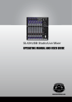
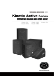
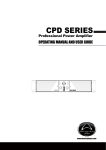
FORCE 12 Powered Mixer
OPERATING MANUAL AND USER GUIDE
www.wharfedalepro.com
FORCE 12
Powered Mixer
TABLE OF CONTENTS
TABLE OF CONTENTS.............................................................................. 1
IMPORTANT WARNINGS & SAFETY INFORMATIONS........................... 2
INTRODUCTION........................................................................................ 3
ABOUT THE FORCE 12............................................................................ 3
FORCE 12 FEATURES.............................................................................. 3
CHANNEL CH1-6....................................................................................... 4
CHANNEL CH7-8....................................................................................... 5
CHANNEL CH9/10..................................................................................... 6
CHANNEL CH11/12................................................................................... 7
FORCE 12 MASTER SECTION................................................................. 8
FORCE 12 MASTER SECTION................................................................. 9
FORCE 12 REAR PANEL........................................................................ 10
DIMENSIONS........................................................................................... 11
USB INTERFACE..................................................................................... 12
QUICK START GUIDE............................................................................. 12
WIRING DIAGRAMS................................................................................ 13
BLOCK DIAGRAM................................................................................... 14
SPECIFICATIONS.................................................................................... 15
WHARFEDALE PRO LIMITED WARRANTY........................................... 16
OPERATING MANUAL AND USER GUIDE
IMPORTANT WARNINGS & SAFETY INSTRUCTIONS
1.
2.
3.
4.
5.
6.
7.
8.
Read these instructions
Follow all instructions
Keep these instructions
Heed all warnings
Do not use this apparatus near water
Clean only with dry cloth.
Do not block any ventilation openings. Install in accordance with the manufacturer’s instructions.
Do not install near any heat sources such as radiators, heat registers, stoves, or other apparatus (including
amplifiers) that produce heat.
9. Do not defeat the safety purpose of a polarised or grounding plug. A polarised plug has two blades with one
wider than the other. A grounding plug has two blades and a third grounding blade. The wide blade or the
third blade is provided for your safety. If the provided plug does not fit into your outlet, consult an electrician
for replacement of the obsolete outlet.
10.Protect the power cord from being walked on or pinched, particularly at the plug, receptacle and or the point
where it exits from the apparatus.
11.Only use attachments/accessories specified by the manufacturer.
12.Only use a stand, tripod, bracket or rack specified by the manufacturer, or sold with the apparatus. When a
rack is used, use caution when moving the rack and apparatus combination to avoid tip-over or injury.
13.Unplug the apparatus during lightning storms or when unused for long periods of time.
14.Refer all servicing to qualified personnel. Servicing is required when the apparatus has been damaged in
any way including but not limited to power supply cord or plug damage, liquid ingress, foreign objects in
the chassis, exposure to rain/moisture or impact damage. In addition the unit must be serviced when you
experience any abnormal operation.
15.CAUTION: These servicing instructions are for use by qualified service personnel only. To reduce the
risk of electric shock, do not attempt to perform any servicing other than that contained in the operating
instructions unless you are qualified to do so. In addition opening the casing will result in your warranty
becoming null and void.
16.Do not install this apparatus in a confined space such as a book case or similar unit. Good ventilation
should be maintained around the apparatus. Any vents, air-inlets or fans should not be obstructed by
objects such as paper, table-cloths, curtains etc.
17.WARNING: To reduce the risk of fire or electric shock, do not expose the apparatus to rain or moisture. The
apparatus should not be exposed to dripping or splashing and objects filled with liquids, such as vases,
should not be placed on the apparatus.
18.WARNING: The mains plug/appliance coupler is used as a disconnect device, the disconnect device shall
remain readily operable.
ATTENTION: RISQUE DE CHOC ELECTRIQUE-NE PAS OUVRIR
19.The lightning flash with arrowhead symbol within an equilateral triangle is intended to alert the user to the
presence of non-insulated “dangerous voltage” within the product’s enclosure that may be of sufficient
magnitude to constitute a risk of electric shock.
- Warning: To reduce the risk of electric shock, do not remove the cover (or back) as there are no userserviceable parts inside. Refer servicing to qualified personnel.
- The exclamation point within an equilateral triangle is intended to alert the user to the presence of
important operating and maintenance instructions in the literature accompanying the appliance.
(Protective earthing terminal) The apparatus should be connected to a mains socket outlet with a
20.
protective earthing connection.
Correct Disposal of this product. This marking indicates that this product should not be disposed with
21.
other household wastes throughout the EU. To prevent possible harm to the environment or human health
from uncontrolled waste disposal, recycle it responsibly to promote the sustainable reuse of material
resources. To return your used device, please use local return and collection systems or contact the retailer
where the product was purchased. They can take this product for safe environmentally friendly recycling.
FORCE 12
Powered Mixer
INTRODUCTION
Congratulations on your purchase of the FORCE 12 portable powered mixer. The Wharfedale Pro FORCE 12
is the result of many years of experience in the use, design and manufacture of professional audio equipment.
We take great pride in engineering and building every Wharfedale Pro product and wish to thank you for
entrusting us with your sound solutions.
From the time Gilbert Briggs built his first loudspeaker in 1932, to the present day, Wharfedale have
maintained the same standard of quality in components, workmanship and performance.
Please take the time to read this manual completely in order to ensure that you get the most from your FORCE
12 portable powered mixer.
ABOUT THE FORCE 12
Designed to be a perfect balance of portability and power the FORCE 12 is suitable for use in a wide range
of portable sound applications. Everything you need to mix and amplify microphones and line level sources is
included in one box, with an ergonomic carry handle to aid transportation.
The one box concept speeds up your setup time and allows you to start your performance quicker than ever
before.
All models feature built in digital FX processing, expanding your creativity and improving your sound quality
without the need for additional expensive and often cumbersome processors. A graphic EQ allows fine tuning
of the overall mix.
FORCE 12 FEATURES
• 500W*2@4Ohms(RMS), 300W*2@8Ohms(RMS), 1300W*2@4Ohms(Peak)
• 12 channels (8 mono & 2 stereo, play & record)
• 10 Line inputs (6 Line, 2 Hi-z, 2 stereo)
• 8 Mic inputs with switchable global +48V phantom power
• Optional RCA&USB connections for 1 stereo channel
• Parallel RCA& Line connections for 1 stereo channel
• 3-band EQ control for each mono channel
• 2-band EQ control for each stereo channel
• Dual 7-band Graphic EQs with routing switch
• 10 channel peak LED indicators and 1 Effects peak LED indicator
• Dual 7-band Master Level LED indicators and 2 Limit LED indicators
• Mute button for all the Mic channels
• FX bypass button and FX Foot Switch to mute FX function
• 56 sorts of stereo effects with LED digital display
• Insert balanced/unbalanced 1/4” TRS jacks for the built-in stereo amplifiers
• 5 low level outputs (Main L/R, Mon Send, FX Send, and Sub Out-80Hz LPF with 1/4” TRS jacks,
and Record Output with RCA jacks)
• Thermal protect, over current protect, DC protect, and output short protect
• Speakon outputs for speakers
• Light weight with 11kg
OPERATING MANUAL AND USER GUIDE
Channel CH 1-6
1 Peak LED-----Illuminates when the signal in this channel starts
clipping.
2 Gain-----Gain control for the input signal for this channel.
3 High-----High frequency shelving EQ at 12 kHz.
4 Mid-----Mid frequency shelving EQ at 2 kHz.
5 Low-----Low frequency shelving EQ at 80 Hz.
6 Mon-----Mon sends signal to a stage monitor.
7 FX-----FX sends signal to the built-in FX processor.
8 Pan-----Places the signal within the stereo field.
9 Level-----Controls the overall volume of the channel
10 Line In-----Balanced/unbalanced 1/4"TRS input for line level
sources.
11 Mic----Balanced XLR microphone input with switchable +48V
Phantom Power (Global Phantom Power switch on the rear
panel of the unit).
FORCE 12
Powered Mixer
Channel CH 7-8
1 Peak LED-----Illuminates when the signal in this channel starts
clipping.
2 Gain-----Gain control for the input signal for this channel.
3 High-----High frequency shelving EQ at 12 kHz.
4 Mid-----Mid frequency shelving EQ at 2 kHz.
5 Low-----Low frequency shelving EQ at 80 Hz.
6 Mon-----Mon sends signal to a stage monitor.
7 FX-----FX sends signal to the built-in FX processor.
8 Pan-----Places the signal within the stereo field.
9 Level-----Controls the overall volume of the channel.
10 Line In-----Balanced/unbalanced 1/4"TRS input for line level
sources.
11 Mic----Balanced XLR microphone input with switchable +48V
Phantom Power (Global Phantom Power switch on the rear
panel of the unit).
OPERATING MANUAL AND USER GUIDE
Channel CH 9/10
1 Peak LED-----Illuminates when the signal in this channel starts
clipping.
2 Gain-----Gain control for the input signal for this channel.
3 High-----High frequency shelving EQ at 12 kHz.
4 Low-----Low frequency shelving EQ at 80 Hz.
5 Mon-----Mon sends signal to a stage monitor.
6 FX-----FX sends signal to the built-in FX processor.
7 Balance-----Places the signal within the stereo field.
8 Level-----Controls the overall volume of the channel.
9 RCA------Line input for CD/Tape, parallel with the Line In L/R.
10 Line In L------1/4"TRS input for line level sources.
11 Line In R------1/4"TRS input for line level sources.
FORCE 12
Powered Mixer
Channel CH 11/12
1 Peak LED-----Illuminates when the signal in this channel starts
clipping.
2 Gain-----Gain control for the input signal for this channel.
3 High-----High frequency shelving EQ at 12 kHz.
4 Low-----Low frequency shelving EQ at 80 Hz.
5 Mon-----Mon sends signal to a stage monitor.
6 FX-----FX sends signal to the built-in FX processor.
7 Balance-----Places the signal within the stereo field.
8 Level-----Controls the overall volume of the channel.
9 RCA------Line input for CD/Tape.
10 USB/Line Switch-----Selects the input source for this channel.
11 USB Interface------Connects to a computer audio interface.
OPERATING MANUAL AND USER GUIDE
FORCE 12 MASTER SECTION
2
1
8
3
9
4
10
5
6
11
7
12
13
14
1
2
3
4
5
6
7
8
9
15
Peak LED-----Illuminates when the Effects clipping
LED Digital Display -----56 sorts of stereo effects can be displayed via LED digital display
FX Send-----Allows for master adjustment of the FX send bus.
FX Select-----Selects the effect type.
FX to Mon-----Routes the FX processor output to the Monitor send.
FX to Mix-----Controls the output level of the internal FX processor to the master buss.
7-band EQ-----Dual 7-band graphic equalizers with fixable A/B EQ Routing.
Bypass-----Used to switch the internal FX processor on or off.
Power LED-----Indicates the main power supply.
10
Phantom Power LED-----Indicates +48v phantom power supplied to all of the Mic inputs. Please check
that all connected microphones can withstand +48v power input.
11
Master Level LEDs----Dual 8 Segment LED metering for the master. If the limit LED illuminates
constantly lower the master level to avoid damage to your loudspeakers.
12
EQ Routing Switch----- Configures the signal routing of the graphic EQs. In the Mode “A”, each EQ
controls the respective output with monitor sends routed unprocessed to the Mon output. In the Mode “B”,
the Mon is processed by the EQ2, and the EQ1 will process both left and right output channels.
13
14
Mute Button ----- Mute/un-mute all the Mic Channels (CH1-8).
15
Mix -----Controls the gain to the Main L/R and also controls the AMP 1 and AMP 2 at the same time if the
EQ Routing switch is setting to “A”, but only controls the AMP 1 if the EQ Routing switch is setting to “B”
Mon-----Controls the gain to the Mon-send, and also controls the AMP 2 if the EQ Routing switch is
setting to “B”
FORCE 12
Powered Mixer
FORCE-12 MASTER SECTION
1
2
4
6
8
3
5
7
9
1:
1 Record Out-----Line level output using phonograph connectors provide connection to
recording devices.
2:
2 FX Send----- Sends the mixed signal to the outside effect processor.
3:
3 FX Foot Switch -----Controls the internal FX processor on or off by a foot switch.
4:
4 Mon Send----- Balanced/unbalanced 1/4'' TRS Monitor send output.
5:
5 Sub Out-----Balanced/unbalanced 1/4'' TRS Sub output with 80Hz low pass filter.
6:
6 Main L-----Balanced/ unbalanced 1/4'' TRS master output for the left channel.
7:
7 Main R-----Balanced/ unbalanced 1/4'' TRS master output for the right channel.
8:
8 Power Amp L-----Insert Balanced/ unbalanced 1/4'' TRS to the AMP1.
9:
9 Power Amp R-----Insert Balanced/ unbalanced 1/4'' TRS to the AMP2.
OPERATING MANUAL AND USER GUIDE
FORCE 12 REAR PANEL
1
Phantom power switch-----Activates the +48v phantom
power for the 8 Mic channels
2
3
4
Power switch-----Turns the unit on or off. Ensure that
AC is supplied and the levels have been turned down to
protect your speakers.
Breaker----- Restorability circuit breaker to protect the unit.
IEC receptacle-----Allows input of the supplied IEC lead
to an AC supply.
5 Speakon output----- For connection to loudspeakers. The
LEFT- RIGHT corresponds to the EQ routing mode A, and the
Mix-Mon to the EQ routing mode B.
10
FORCE 12
Powered Mixer
DIMENSIONS
324
535.79
330.86
11
OPERATING MANUAL AND USER GUIDE
USB INTERFACE
The USB connector enables computers with USB connectivity to interface directly with the FORCE
12 mixer for full duplex recording and playback. In recent years the introduction of USB connectivity
has ushered a new appreciation of the capabilities of computer audio, helping to fuse both digital
and analogue and open up endless possibilities for the recording musician.
The internal AD (Analogue to Digital) and DA (Digital to Analogue) converters are 16-bit/48KHz
enabling recording and playback above CD quality, ensuring that recordings that you make with a
FORCE 12 have outstanding quality.
The FORCE 12 is fully class compliant and requires no drivers when used with modern operating
systems. Mac OSX, Windows XP, Vista and 7 will require no additional driver software.
Windows XP Installation
Simply choose the device in the following location: Start/Settings/Control Panel/Sounds and Audio
Devices/Audio
Mac OSX Installation
Simply select as an input and output device using the "Audio MIDI Setup" page, you can find this
easily using the spotlight function.
QUICK START GUIDE
In order to get up and running with your FORCE 12 follow the steps below:
1.Zero the mixer. This involves setting all level and send controls to minimum and all EQ controls to
0dB.
2.Make all connections for audio and power as per the wiring diagrams:
• Ensure that the power switch is on the off position before connecting the AC supply.
3.If your microphones require phantom power, use the rear panel switch to activate +48V supply.
4.Turn the power switch on.
5.Raise the level control for each of your connected sources, ensure that the Peak LED does not
constantly illuminate.
6.Raise the Mix Level control until you achieve the desired Sound Pressure Level (SPL).
NOTE
If the sound becomes distorted at higher volumes you may need to add extra equipment to achieve
the desired SPL, otherwise you may cause permanent damage to your system by overloading it.
12
FORCE 12
Powered Mixer
WIRING DIAGRAMS
13
OPERATING MANUAL AND USER GUIDE
BLOCK DIAGRAM
14
FORCE 12
Powered Mixer
SPECIFICATIONS
Model
FORCE 12
Power Output
500W*2 RMS into 4 ohms(THD=1%@ 1KHz)
550W*2 RMS into 4 ohms(THD=5%@ 1KHz)
260W*2 RMS into 8 ohms(THD=1%@ 1KHz)
290W*2 RMS into 8 ohms(THD=5%@ 1KHz)
1300W*2 Peak into 4 ohms
700W*2 Peak into 8 ohms
Maximum output level
Main L/R Mon Send
Sub Out(60Hz)
Fx Send
REC OUTPUT(Unbal out)
+25dBu (14V) @THD=0.12%
+25dBu (14V) @THD=0.12%
+10dBu (2.5V) @THD=0.12%
+5dBu (1.4V) @THD=0.12%
THD+N
Speakon out
Mix/monitor out
Mix/monitor out
<0.13% @ 40Hz-20KHz 300W/4ohm
<0.005% @ 20Hz-30KHz MIC/LINE mono
<0.01% @ 20Hz-30KHz LINE stereo
Speakon out
Mix/monitor out
MON-SEND out
Fx Send out
-61dBu (All channel level 0dB, Main level 0dB)
-87dBu (All channel level 0dB, Main level 0dB)
-95dBu (All channel level 0dB, Main level 0dB)
-98dBu (All channel level 0dB, Main level 0dB)
Hum & Noise
Frequency Response
20Hz-40kHz +1dB/-3dB (Mic/Line mono, Line stereo)
Maximum voltage gain
97dB input mic to Speakon out
67dB input mic to Mix/Mon
47dB input mic to Rec out
67dB input line to Speakon out
59dB input tape/USB to speakon out
Input channel equalisations
High 12KHz shelving
Mid 2KHz shelving
Low 100Hz shelving
Maximum: +/-15dB "
Graphic equaliser
Dual 7-band (60Hz, 120Hz, 480Hz, 1KHz, 4KHz,
8KHz, 16KHz)
Maximum: +/-12dB"
Digital effects
56 Effects
ROOM: r1 Closet; r2 Small ambient room;
r3 Small bathroom; r4 Medium bathroom;
r5 Large bathroom; r6 Small empty room;
r7 Medium empty room ;r8 Large empty room
PLATE: P1 - P5
HALL: h1 Medium hall 1; h2 Medium hall 2
h3 Medium hall 3; h4 Large hall 1
h5 Large hall 2; h6 Large hall 3
h7 Church; h8 Cathedral
GATED REVERB: g1 - g3
CHORUS: c1 - c4 Chorus 1-4
c5 - c8 Chorus with reverb 1-4
FLANGER: F1 - F6 Flanger 1-6
F7 - F9 Flanger with reverb 1-2
ROTARY SPEAKER: S1 - S7
DELAY: D1 - D9
Protection
Power ON/OFF Mute; DC detection; Overload and
short detection; Temperature detection
Power
AC100-120V~ 50/60Hz or AC220-240V~ 50/60Hz
Product dimension(H*W*D)
540*330*330mm (22*13*13 in)
Net weight
11Kg (24lbs)
15
WHARFEDALE PRO LIMITED WARRANTY
Wharfedale Pro products are warranted of manufacturing or material defects for a period of one
year from the original date of purchase. In the event of malfunction, contact your authorized
Wharfedale Pro dealer or distributor for information.
*Be aware that warranty details may differ from country to country. Contact your dealer or
distributor for information. These terms do not infringe your statutory rights.
Wharfedale Professional
IAG House, 13/14 Glebe Road, Huntingdon, Cambridgeshire, PE29 7DL, UK
www.wharfedalepro.com
Wharfedale Professional reserves the right to alter or improve specifications without notice.
All rights reserved © 2011 Wharfedale Pro. Wharfedale Pro is a member of the IAG Group.