1
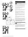
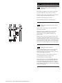
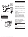
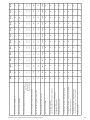
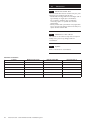
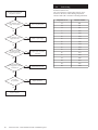
Please read these instructions before installing or commissioning.
Potterton Solar - Solar Thermal Domestic Hot Water System
should only be installed by a competent person.
Please leave these instructions with the user for safe keeping.
Commissioning, Maintenance & Servicing Guide
Potterton Solar - Solar Thermal Domestic Hot Water System
© Baxi Heating UK Ltd 2007.
Index
2 Index
3 Commissioning of system
General information
Flushing and filling the system
5 Commissioning of hydraulic station
Checking/setting pressure
Checking/adjusting flow rate
Installation of thermal insulation
7 Commissioning of solar controller
Overview of display
Button function
Operating menu
Menu structure
"Info"
"Programming"
"Manual operation"
"Basic adjustment"
Controller functions
21 Commissioning record
22 Servicing and maintenance record
24 Maintenance
Check heat transfer fluid
Maintenance of the collector
25 Fault finding
Failures with error message
Resistance table
Flow charts
28 Spares
30 Warranty
© BAXI Heating UK Ltd 2007. All rights reserved. No part of this publication may be reproduced
or transmitted in any form or by any means, or stored in any retrieval system of any nature
(including in any database), in each case whether electronic, mechanical, recording or otherwise,
without prior written permission of the copyright owner, except for permitted fair dealing under
Copyrights, Designs and Patents Act 1988.
Applications for the copyright owner’s permission to reproduce or make other use of any part of
this publication should be made, giving any details of the proposed use to the following address:
The Company Secretary, BAXI Heating UK Ltd,The Wyvern Business Park, Stanier Way, Derby DE21 6BF.
Full acknowledgement of author and source must be given.
WARNING: Any person who does any unauthorised act in relation to a copyright work may be
liable to criminal prosecution and civil claims for damages.
2
Potterton Solar - Solar Thermal Domestic Hot Water System
1.0
1.1
Commissioning of system
Commissioning - General
The Potterton Solar system uses a sealed system indirect
solar primary circuit which must be filled with the solar
heat transfer fluid provided. This is pre-diluted to the
appropriate strength (40% glycol/60%water) and should
not be diluted further. Use only the fluid supplied.
Additional canisters of solar fluid are available in 10 litre
(5119550) and 20 litre (5119549) bottles.
DO NOT mix the fluid with other types.
The system should be filled when there is no direct
radiation from the sun. If direct radiation occurs the
collector panels should be shaded by covering them
during filling and flushing.
Although the solar heat transfer fluid is non corrosive
and biodegradable appropriate precautions should be
taken when handling.
- Wear protective gloves and goggles.
- Wash with soap and water if the fluid comes into
contact with skin.
- If fluid gets into eyes, immediately rinse with large
quantities of clear running water.
- A full safety and specification sheet can be obtained
by request.
The solar heat transfer fluid must be pumped into the
system.The pump can be electric or manual but must be
capable of producing a pressure of at least 2 bar.
The system should be thoroughly flushed to remove any
contaminants in the solar primary circuit prior to filling
with the heat transfer fluid
Potterton Solar - Solar Thermal Domestic Hot Water System
3
Fig. 1
3
5
4
1.0
1.2
Commissioning of system
Flushing the pipework
Before the system is commissioned the pipework must
be flushed to remove any contaminants. It is recommended
that this is done using the solar heat transfer fluid as it
will be impossible to fully drain all parts of the system.
1
Connect the flushing pipes to the fill & drain valve on
the safety group (Fig. 1 Item 1) and to the fill & drain
valve on the flow meter (Fig. 1 Item 2).
2
Open the fill & drain valves.
6
7
Turn the slot of the adjusting screw (Fig. 1 Item 3) in the
return so the slot is vertical to open the non-return
valve.
Turn the left hand isolating valve with integral
thermometer in the flow (Fig. 1 Item 4) in the direction
indicated by the arrow (to a 45° position) to open the
non-return valve.
Fig. 2
Ensure that the right hand isolating valve with integral
thermometer in the return (Fig. 1 Item 5) is open
indicated by the dot on the thermometer bezel being
at the top.
Turn the slot of the adjusting screw of the flow meter
(Fig. 1 Item 6) in the return vertically to open the flow
limiter (Fig. 1 Item 7).
Filling pump
Flush the solar primary pump by pumping the fluid into
the system via the fill and drain valve on the safety group.
Close right hand isolating valve (dot on thermometer
bezel at 9 o’clock position). Flush solar primary pipework
and panels via the fill and drain valve on the safety group.
If reusing flushed fluid ensure this is filtered before reintroducing into the system (see Fig. 2).
Filter
Solar fluid
Fig. 3
Solar fluid
Filling the pipework
Close the fill and drain valve (Fig. 3 Item 2) on the flow
meter. Open the righthand isolating valve (Fig. 3. Item 1)
with integral thermometer by turning so that the dot on
the bezel is at the top. Fill the solar primary system by
pumping in fluid until the system pressure reads 1.5 to
2.0 bar. Close the fill and drain valve (Fig. 3. Item 3) on
the safety group.
1
3
2
4
1.3
Potterton Solar - Solar Thermal Domestic Hot Water System
2.0
2.1
Commissioning of hydraulic station
Check pressure in the solar primary
pipework
After flushing and filling the solar primary system with
heat transfer fluid the pressure must be checked.
Pressure test the system (6 bar). Observe the maximum
pressure ratings of all components concerned.
Check the solar heating system for leaks.
Close the fill and drain valve on the safety group.
Fig. 4
2.2
2
1
Ensure the solar primary system is free
from air
Switch on the power supply to the solar differential
temperature controller.
Manually switch the circulation pump ON and OFF
via the solar differential temperature controller
(see section 3.1.7) to pump fluid around the solar
primary system.
Turn the pump off and open the airbleed screw on the
air separator (Fig. 4 Item 1). Bleed any air from the air
separator. If the system pressure drops top up by opening
the fill and drain valve (Fig. 4 Item 2) on the safety group
and pumping in more solar fluid to restore the pressure.
This must be repeated until the pressure remains stable.
2.3
Setting the system pressure
During commissioning, the system pressure should be
0.7 bar above the static pressure (1 metre height
differential equals 0.1 bar). However, it must be at least
1.5 bar and no higher than 2.2 bar.
Determine the system pressure when the system is
cold (20°C).This should be recorded on the
Commissioning Record Sheet (page 21).
If the pressure is too low you should pump additional
heat transfer fluid into the system; the fill & drain valve
on the safety group (Fig. 4 Item 2) needs to be opened
for this purpose.When system pressure is correctly set,
ensure the fill and drain valve is closed and remove filling
hose from safety group.
Potterton Solar - Solar Thermal Domestic Hot Water System
5
2.0
Fig. 5
1
2
Checking and adjusting the flow rate
Adjust the flow rate when the system is cold (20°C)
(see Fig. 5).
The flow rate should be adjusted to give the optimum
flow rate depending on the number and type of
collector panels connected.
5
Turn the slot of the adjusting screw (Fig. 5 Item 1) below
the return temperature gauge horizontally to close the
non-return valve.
Turn the l.h. isolating valve with integral thermometer in
the flow (Fig. 5 Item 2) as far as it will go in the direction
indicated by the arrow to close the non-return valve (dot
on bezel on top).
3
4
Table 1
2.4
Commissioning of hydraulic station
Turn the slot of the adjusting screw (Fig. 5 Item 3) in the
return vertically to open the flow limiter on the flow
meter (Fig. 5 Item 4).
Manually operate the solar pump (see section 3.1.7).
Flow rate
(when system is cold)
Collectors
1
2
3
Set the solar pump switch (Fig. 5 Item 5) so that the
required flow rate is achieved or exceeded with the
lowest possible setting.The flow limiter adjusting screw
(Fig. 5 Item 3) can be used to fine-tune the flow rate.
l/min
approx. 2
approx. 4
approx. 6
Depending on the number and type of collectors installed,
set the required flow rate from table (See Table 1).
The float in the flow meter will indicate the circulation
flow rate through the flow meter sight glass.
Adjust screw of the flow limiter (Fig. 5 Item 3) with a
screwdriver, until the upper edge of the float in the sight
glass indicates the required flow rate.
Fig. 6
Set manual pump operation to off.
1
3
2
6
Potterton Solar - Solar Thermal Domestic Hot Water System
2.5
Installation of the thermal insulation
Refit the controller mounting moulding (Fig. 6 Item 1)
onto the rear moulding.
Push the front thermal insulation (Fig. 6 Item 2) against
the rear thermal insulation section (Fig. 6 Item 3) until it
clips into place.
Fig. 7
Commissioning of solar controller
3.0
3.1
1
2
3
Overview of display and operating elements
(see Fig. 7).
Number
5
1
Description
3
Control button exit / break-off
2
4
4
5
Display with graphic symbols
Control button scroll upwards / +
Control button scroll downwards / –
Control button choice / confirmation
3.1.1 Explanation of graphic symbols
Graphic symbol
Description
Indication in operation
Main Menu
Menu "Info"
Menu "Programming"
Menu "Manual operation"
When symbol flashes it is possible for it to be
selected. If that symbol is chosen by pressing the
button, the symbol remains static (not flashing).
Menu "Basic adjustment"
Graphic symbol
Description
Indication in operation
dT
Temperature difference
Indicator values
min
max
min
0:00
1
Max
23:59
1
ºC
K
h
kWh
Min value
Max value
Appears when minimum values are indicated
Appears when maximum values are indicated
Timeframe 1 start
Appears when the differential controller is active
(timeframe 1-3) or tube collector is active (timeframe 4)
Timeframe 1 stop
Appears when the differential controller is active
(timeframe 1-3) or tube collector is active (timeframe 4)
5 x 7 segment display.
Presentation of figures 00000 to 99999
Display of all values, display flashes when
a value is changed
Temperature in Celsius
Temperature difference in Kelvin
Operating hours
Productivity indication in kWh
Potterton Solar - Solar Thermal Domestic Hot Water System
7
3.0
Graphic symbol
Description
Commissioning of solar controller
Indication in operation
Measuring points assignment
Temperature measuring point collector array 1
Temperature measuring point collector array 2
Temperature measuring point storage tank 1 lower
(storage tank 1 charging)
Temperature measuring point storage tank lower
(storage tank 2 charging)
Temperature measuring point collector - return
Temperature measuring point storage tank upper
(thermostat function)
Antifreezing sensor or universal temperatures
measuring point (T6) (no sensor monitoring)
2nd temperature differential controller
Operating hours, energy productivity measurement
Status indication
!
ok?
8
Solar circulation pump
Symbol revolves when solar circulation pump is on
Switch output 1 is active
Appears when switch output 1 is active (on)
Switch output 2 is active
Appears when switch output 2 is active (on)
Switch output 3 is active
Appears when switch output 3 is active (on)
Reference to system fault
Display flashes when a fault occurs in the system
Safety query for value changes which are to be stored
Potterton Solar - Solar Thermal Domestic Hot Water System
Input value can be either
rejected or
accepted
3.1.2 Button function
Operation and programming of the Potterton Solar
differential temperature controller is by means of 4 operating
buttons. By means of pressing these buttons you can:
• recall display values
• carry out controller adjustments
The graphic symbols on the display step through the
operating structure and show clearly the current menu
points, display values or parameters.
Operating buttons have the following functions:
Button
Function
Description
"Call"
"Down"
• Call up of main menu, step down through menu
• Value change: Decrease of the indicated value by 1, holding the button down will
automatically decrease values
"Up"
"+"
"Scroll left"
"Exit"
"Break-off"
"Scroll right"
"Choice"
"Confirmation"
• Step up through menu
• Value change: Increase of the indicated value by 1, holding the button down will
automatically increase values
•
•
•
•
In main menu, scrolls to the left
Exit current menu
Exit menu point
Break-off value change without storing
• In main menu, scrolls to the right
• Choosing one menu point
• Confirmation of value change, stores value change
Example of setting procedure
Button
Function
Icon after operation step
Exit menu's "Info"
Currently selected menu icon will flash
"Exit"
Choosing menu "Programming"
Chosen menu icon will flash
"Scroll right"
"Call"
"Down"
"Choice"
"Up"
"Confirm"
"Confirm"
Description
Max
65°C
Call up menu "Programming", the first menu
point appears
dT min
3K
Repeated pressing up to menu point
"S1 dTmin" appears
dT min
3K
Choosing presented character
When chosen, value to be changed will flash
dT min
4K
dT min
4K
dT min
4K
Increase of parameter
ok?
Confirmation of the character
"ok?" icon will flash
Storing of the parameter
When stored, icon will stop flashing
"Exit"
Exit menu "Programming"
Currently selected menu icon will flash
"Scroll left"
Choosing menu "Info"
Chosen menu icon will flash
"Call"
60°C
Potterton Solar - Solar Thermal Domestic Hot Water System
Call up menu "Info"
9
3.0
Commissioning of solar controller
3.1.3 Operating menu
To make the operation of the controller clear, operating
and display functions are divided into 4 main menus.
These are
• Info
• Programming
• Manual operation
• Basic adjustment
Each active menu is shown in the upper line of the
display by its corresponding icon.
Menu
Info
Programming
Manual operation
Basic adjustment
Description
Main menu for automatic regulation of solar system
• Indication of current measured values
• Indication of system condition
• Indication of error messages
• Indication of operating hours and energy productivity (if installed)
Changes to programmable values (parameters)
Note: Changes can affect system functions!
Switching on and off connected pumps / valves by hand. Overrides automatic regulation.
Information about basic adjustment for system function
Important
Adjustments and changes in this menu must be carried out only by a competent
installer or service engineer.
10
Potterton Solar - Solar Thermal Domestic Hot Water System
3.0
Commissioning of solar controller
3.1.4 Overview: Construction of menu structure
The overview shows the whole menu structure.
According to basic adjustment and system type some
menu points may not be displayed.
Info
Program
Manual operation
Storage cylinder1
Td max (Td on)
Pump2 / Valve1
off / on
Current collector temperature
/ Collector1
Maximum temperature
storage cylinder1
Maximum collector temperature
/ Collector1
Storage cylinder1
Td min (Td off)
Minimum collector temperature
/ Collector1
Pump1 off / on
Heating / Cooling / Temperature
differential controller
off / on
Basic setting
Collector protection function
off / on
Collector protection
temperature
Re-cooling
off / on
Current storage cylinder
temperature / storage1 at bottom
Maximum temperature of
storage cylinder2
Maximum storage cylinder
temperature / storage1 at bottom
Storage cylinder2
Td min (Td off)
Yield estimation
off / on
Start temperature
Heating / cooling
Glycol percentage
Temperature differential
controller:
Maximum temperature of the
heating target Tmax
Controlling time in
seconds
Minimum storage cylinder
temperature / storage1 at bottom
Storage cylinder2
Td max (Td on)
Current storage cylinder temp /
storage2 at bottom / collector 2
Minimum
pump rotating speed in %
Maximum storage cylinder temp /
storage2 at bottom / collector 2
Hysteresis temperature
heating / cooling Td
Minimum storage cylinder temp /
storage2 at bottom / collector 2
Current collector
temperature - return line
Current temperature
heating / cooling /
differential controller
heating source
Current temperature
frost protection sensor /
differential controller heating
target / universal measuring
point T6
Operating hours pump1
Yield storage1
Operating hours pump2
Yield storage2
Re-cooling
temperature
Tube collector
off / on
Glycol type
Volume flow
Temperature differential
controller:
Minimum temperature of the
heating source Tmin
Storage cylinder priority
Temperature differential
controller:
Hysteresis Tdmax
Frost protection
off / on
Temperature differential
controller:
Hysteresis Tdmin
Frost protection sensor
assignment
Timeframe stop 1,2,3 for the
independent controller, 4 for the
tube collector function
Independent controller
assignment: Cooling, heating,
temperature differential
controller
Timeframe start 1,2,3 for the
independent controller, 4 for the
tube collector function
Set time
Frost protection:
start temperature
Sensor assignment for the
independent controller
Select basic configuration
Potterton Solar - Solar Thermal Domestic Hot Water System
11
3.0
Commissioning of solar controller
3.1.5 Menu “Info”
In this menu mode all measured values and operating
states are shown.
If the values are marked as “resettable”, they may be
reset in the following way:
Choose the value with buttons
and
Reset value by means of the button
Message “OK?” confirm with
12
= no or
= yes
Indication
Description
Reset possible
75ºC
Indication of current collector temperature
no
min. 12ºC
Indication of minimum collector temperature
Re-settable to current temperature
yes
max. 105ºC
Indication of maximum collector temperature
Re-settable to current temperature
yes
52ºC
Indication of current temperature storage tank (lower)
no
min. 40ºC
Indication of minimum temperature storage tank (lower)
Re-settable to current temperature
yes
max. 67ºC
Indication of maximum temperature storage tank (lower)
Re-settable to current temperature
yes
25ºC
Indication of universal temperature measuring points (T3)
no
55ºC
Indication of current temperature storage tank thermostat
no
60ºC
Indication of current temperature collector return
no
60ºC
Heating, cooling, temperature differential controller
heat source. Sensor T1...T6
no
35ºC
Temperature differential controller
heat target
no
1234 h
Operating hours for charging storage tank
Resettable to 0 h
Yes
927 kWh
Energy productivity for storage tank
Resettable to 0 kWh
Yes
Potterton Solar - Solar Thermal Domestic Hot Water System
3.0
Commissioning of solar controller
3.1.6 Menu “Programming”
All adjustable parameters can be checked in this menu
and, if necessary, changed.The default factory set values
will usually give efficient, problem free operation.
The number of indicated values depends on the
controller type and the adjusted additional functions.
Only the required values are shown at each menu step:
Indication
Description
Value range
Defaults
max
65ºC
Storage 1/2:
Maximum temperature
15..95ºC
65ºC
dT max
7K
Storage 1/2: Hysteresis (Tdon)
3..40 K
7K
dT min
3K
Storage 1/2: Hysteresis (Tdoff)
2..35 K
3K
Setting the speed control of the pump
100% = speed control off
30%..100%
100%
13:21
Clock
0:00...23.59
12:00
min
40ºC
Temperature start for the function
heating/cooling
20..90ºC
40ºC
dT
10K
Hysteresis heating/cooling
1..30K
10K
max
65ºC
Differential controller: Maximum
temperature of heat target Tmax
15..95ºC
65ºC
min
15ºC
Differential controller: Maximum
temperature of heat source Tmin
0..95ºC
15ºC
dTmax
7K
Temperature differential controller:
Hysteresis dTmax
3..40K
7K
dT min
3K
Temperature differential controller:
Hysteresis dTmin
2..35K
3K
min
00:00
1(2,3)
Timeframe 1(2,3): Start
for the independent controller
0:00...
23.59
00:00
max
23:59
1(2,3)
Timeframe 1(2,3): Stop
for the independent controller
0:00...
23:59
23:59
min
6:00
4
Timeframe 1(2,3): Start
for the tube collector function
0:00...
23:59
6:00
max
20:00
4
Timeframe 1(2,3): Stop
for the tube collector function
0:00...
23:59
20:00
min
100
2
Potterton Solar - Solar Thermal Domestic Hot Water System
13
3.0
Commissioning of solar controller
3.1.7 Menu “Manual operation”
For commissioning, service and test purposes the solar
primary system can be manually operated. For this purpose
the switch outputs may be disconnected or connected.
During manual operation there is no automatic regulation
of the system.To avoid inadmissible operating states this
mode of operation changes into “Indication” after ca.
8 hours and the automatic regulation is activated again.
Indication
14
Description
Value range
Switching on / off switch output A1 (solar circulation pump) by hand
0 = off
1 = on
Switching on / off switch output A2 (pump2 / valve1) by hand
0 = off
1 = on
Switching on / off switch output A3 (cooling, thermostat or 2nd temperature
difference controller function) by hand
0 = off
1 = on
Potterton Solar - Solar Thermal Domestic Hot Water System
3.0
Commissioning of solar controller
3.1.8 Menu “Basic adjustment”
Adjustments and changes in this menu must be carried
out only by a competent installer or service engineer.
Incorrect adjustments may adversely affect the function
of controller and solar primary system.
To avoid accidental changes in menu “Basic adjustment”,
it is not editable in normal functioning but has only a
display function.To be able to carry out any changes, this
menu must be chosen within the first minute after
switching on the appliance. The basic adjustment menu is
‘blocked’ automatically one minute after if no buttons are
pressed or one minute after switching on the appliance.
Indication
Parameter / value
Description
Value
range
Factory
set-up
Collector protection
0 = off
1 = on
0 = off
0 = off
1 = on
0 = off
0–
0
1–
120ºC
Start temperature for the collector protection
110..150ºC
3–
40ºC
30..90ºC
40ºC
4–
0
Target temperature for the storage after
collector protection activity
0
Yield estimation off/on
0 = off
1 = on
0 = off
5–
Time controlled circulation with
tube collectors
0 = off
6–
0
Glycol types (see table below)
0 = off
1 = on
0...10
50
8–
1,0
Volume flow: Litre per impulse - flow meter
0 ... 100%
5% - steps
0
9–
240
Time controlling in s
11 –
0
Frost protection on/off
6
Sensor assignment - Frost protection
2–
7–
10 –
12 –
0
Re-cooling function (only when collector
protection is on)
50
Glycol percentage
1
Storage priority
13 –
3
Start temperature for the frost protection function
15 –
5
Sensor assignment for the independent controller (source)
14 –
16 –
0
Select cooling thermostat
or temperature differential controller
0
System configuration
Glycol types (point 6):
0
1
2
3
4
5
Anro
IIexan E, Glythermin
Antifrogen L
Antifrogen N
IIexan E
IIexan P
6
7
8
9
10
Potterton Solar - Solar Thermal Domestic Hot Water System
Tyfocor
Dowcal
Dowcal
Dowcal
Tyfocor
0,5 ... 25 I/I
0,5l - steps
120ºC
1,0
30...480
240
0 = off
1 = on
0
1...2
1
1...6
6
0 = off
1 = cooling
2 = heating
3 = temperature
differential controller
0
-20ºC ... +7ºC
1...6
0...4
3
5
0
L5.5 - supplied
10
20
N
LS
15
3.0
Commissioning of solar controller
3.1.9 Controller functions
The Potterton Solar differential temperature controller
contains many functions to regulate and monitor the
solar primary system. Including
- controller functions for heating the solar cylinder
- functions for system protection and system monitoring
- additional functions (other accessories may be required
to achieve these functions).
3.1.10 General controller functions
The controller collects the temperatures of various
measuring points and determines the right time to charge
the storage tank on account of programmed (additional)
functions and controller parameters.
3.1.11 Cylinder heating by solar primary system
Switching action can be adjusted through dTmax (dTon)
and dTmin (dToff), but dTon cannot be set lower than dT
off + 1K .The solar cylinder is heated by operating the
solar pump on output A1 up to the set maximum storage
temperature. Pump operation is allowed as long as the
collector panel temperature exceeds the cylinder
temperature by a set amount.
Corresponding values in menu
“Basic adjustment”
“Programming”
---
Maximum temperature
---
dT max (dT on)
Switch-on temperature difference
---
dT min (dT off)
Switch-off temperature difference
3.1.12 Systems with two storage cylinders
For systems with more than one storage cylinder (System
Types 1 and 2) the cylinder heating can be optimised
depending on the energy supply. Usually the cylinder with
lower priority will have a lower temperature than that
with the higher priority. Re-directing the energy to the
lower priority cylinder will lower the temperature in the
collector array.To “reinforce” the collector temperature
the heating of the lower priority cylinder will be
interrupted for a short while at fixed intervals. If the
heating criteria for the higher priority cylinder is fulfilled
then the lower priority cylinder will be heated.
The higher priority cylinder can be selected in the
“Basic Settings” menu point no. 10.
16
Potterton Solar - Solar Thermal Domestic Hot Water System
3.1.13 Rotational speed regulation
The solar circulation pump on 230V-outputs A1 and
A2 can be operated either in switch-mode (two-point
controller) or in a rotational speed regulated way.
If the rotational speed regulation is activated the pump
power is adjusted by a controller so that switch-on
temperature difference “Storage tank dTmax” is kept
constant as much as possible. At lower deviation of
“Storage tank dTmax” the pump is operated with the
lowest power till the switch-off wave is reached.
Corresponding values in menu
“Basic adjustment”
“Programming”
---
T[ºC]
Rotational speed min <100%
Thermostat
(Storage top)
3.1.14 Thermostat (heating)
dT
10k
TTh
40ºC
on
A3
off
t
Heating on (A3)
The thermostat is a control circuit that’s independent
from the storage loading.Thus an auxiliary heating in
the top area of the storage cylinder is made possible.
The output A3 will be:
• Switched on, when the temperature falls below the
adjusted start level.
• Switched off, when the temperature reaches the
adjusted start level + hysteresis.
Corresponding values in menu
“Basic adjustment”
“Programming”
14 -- 2
Start temperature max ºC
15 -- 5
Hysteresis Td in K
Timeframe (1…3) Start: min time
Timeframe (1…3) Stop: max time
3.1.15 Thermostat (cooling)
In order to optimise the energy yield, it could be useful
to “redirect” the solar energy, or to take it away from
the storage when the storage temperature reaches a
certain level.
When the sensor reaches the start temperature, output
A3 will be switched on.When the temperature level falls
below the start temperature hysteresis, the output A3
will be switched off.
Corresponding values in menu
“Basic adjustment”
14 -- 1
15 -- 5
“Programming”
Start temperature max ºC
Hysteresis Td in K
Timeframe (1…3) Start: min time
Timeframe (1…3) Stop: max time
Potterton Solar - Solar Thermal Domestic Hot Water System
17
3.1.16 Temperature difference control
The temperature difference control manages an output
according to adjustable temperature differential criteria.
The function is independent from all the other functions.
TDiff1 is the temperature of the heating source and TDiff2
of the heating target. Output A3 will be switched on
regarding the conditions below, when a timeframe is active.
Corresponding values in the menu
“Basic Setting”
14 -- 3
15 -- 5
“Programming”
Maximum temperature heating target max ºC
Minimum temperature heating source min ºC
Hysteresis Td max in K
Hysteresis Td min in K
Timeframe (1…3) Start: min time
Timeframe (1…3) Stop: max time
A3 on
TDiff >= TDiff2 + Diff.Tdmax and
TDiff2 < Diff.Tmax – 1 and
TDiff1>=Diff.Tmin + 1
A3 off
TDiff1 < TDiff2 + Diff.Tdmin or
TDiff2 >= Diff.Tmax or
TDiff1<Diff.Tmin
3.1.17 Tube collector
The function “tube collector” can be switched off/on in
the “Basic setting” menu – point 4.The timeframe 4 in the
“Program” menu makes it possible to activate this function
only for a certain period of time (sunshine period).When
activated, the solar pump will be switched on every 30
minutes for a period of 30 seconds.This is necessary, to
measure a temperature change in the collector if there
was no circulating for a long period of time.
Corresponding values in menu
“Basic Setting”
4 -- 1
“Programming”
Timeframe (4) Start: min time
Timeframe (4) Stop: max time
3.2.1 Sensor monitoring
The sensors necessary for control functions and their
connecting cables are monitored regarding break and
short circuit. If a faulty sensor is recognised by the
software, the symbol ! is shown. By scrolling up and
down you can find an error source.
!
Indication
X
18
The use of temperature sensors of the wrong type
can also lead to an error message
Meaning
Short circuit on temperature sensor of the current measuring point
Break on temperature sensor of the current measuring point,
circulation error at activated energy productivity measurement
Potterton Solar - Solar Thermal Domestic Hot Water System
3.2.2 Flow monitoring
If the energy productivity measurement option is
deactivated, the temperature difference between
collector and storage tank is checked.
If it exceeds the amount of (60K + dTmax), it is then
interpreted as an error because in the case of normal
system dimensioning and a pump switched on such large
differences cannot take place.
If the energy productivity measurement option is
activated, the flow amount when the pump is switched
on is checked. If for 15 minutes no flow is recognised
it is evaluated as an error.
Error message is automatically reset after eliminating
the failure.
Indication
+
Meaning
Missing circulation in solar circuit
!
3.2.3 Collector protection / Re-cooling
This function can be switched on/off in the “Basic settings”
menu.
High temperatures can destroy antifreeze liquids.Therefore,
the maximum collector temperature should be restricted.
When all storages have been loaded to the limit, the solar
pump is switched off. If the collector temperature rises
above “T collector max”, the solar pump is switched on,
until the collector temperature drops by 10K. Part of the
energy is lost in the pipes, the rest is loaded in the storage,
which results in increasing the storage temperature above
the adjusted maximum storage temperature. For security
reasons the function will be interrupted if the storage
reaches 95ºC.
If the storage temperature is bigger TStmax+2K and the
collector temperature is 10K below TSt, then the re-cooling
function is activated.The redundant storage energy will be
released through the collector in order to assure reserves
for the next loading cycle.
The re-cooling ends when TSt drops below the value “recooling till…” in the “Basic settings” menu, point 3, or
when the collector temperature >= the storage
temperature – 2K.
The re-cooling function can be active only when the
collector protection function is on.
Corresponding values in menu
“Basic SETTINGS”
0 -- 1
1 -- 120ºC
“Programming”
---
2 -- 1
3 -- 40ºC
3.2.4 System protection function
The system protection function switches the system off if
the “maximum collector temperature” is exceeded by 10K.
As soon as the temperature drops below the “maximum
collector temperature”, the system is started up again.This
function has higher priority and is always active, regardless
of whether the collector protection is on or off.
Potterton Solar - Solar Thermal Domestic Hot Water System
19
3.2.5 Frost protection
This function can be switched on/off in the “Basic settings”
menu, point 11 and the start temperature can be adjusted
in point 13. Furthermore, a frost protection sensor can be
selected (T1-T6, point 12).
For systems driven without or with very low amounts of
antifreeze, the pipes and the collector have to be protected
from freezing. For this purpose, the selected frost
protection sensor measures the temperature at an exposed
place, e.g. blank pipes before the collector. If the measured
value is lower than the start temperature, the solar pump
is activated until the adjusted frost protection start
temperature +5K is reached.The minimum runtime of
the pump is 5 minutes.
For security reasons the function is deactivated if the
temperature of the priority storage falls below 5ºC.
3.2.6 Energy productivity measurement
For the purposes of energy productivity measurement
(solar gain), a sensor on the collector return line and a
flow meter are required.The yield value is calculated
from the values of the temperature difference between
the collector and collector return line and the value
measured by the flow meter. This function is switched on
and off in the “Basic settings” menu.
Corresponding values in menu
“Basic Setting”
“Programming”
5 -- 1
“info”
---
XXXX kWh
3.2.7 Operating hours meter
So long as the storage tank is charged by a pump, the
operating hours meter records for each separate pump.
The number of operating hours can be read in menu
“info” and for each pump separately reset to 0.
Corresponding values in menu
“Programming”
---
20
Potterton Solar - Solar Thermal Domestic Hot Water System
“info”
XXXX h
Commissioning record
The following chart should be completed during Commissioning of the system.
Installer:
Contact details:
Original installation date:
_______________________________
_______________________________
_______________________________
General Commissioning
All pipework correctly installed, identified and
earth bonded
Solar primary system filled with heat transfer
fluid supplied
System pressure test carried out
Solar expansion vessel charge pressure checked
and set
Air vented from system
Exposed pipework insulated using high-temp and
weather resistant insulation
Panel fixing bracket positions weatherproofed
where necessary
Panel fixings checked and secure
If any factory values are changed please enter the new values in the
table below.
❑
Adjustable in menu
"Programming"
❑
Storage tank1:
Maximum storage temperature
❑
❑
bar
❑
❑
bar
Solar primary flow when cold
l/min
Collector temperature sensor correctly installed
and secured
Pipe entry points to building weatherproof
❑
Record all operational parameters set
(see separate table)
Pump operation tested in automatic and manual
modes
All cables correctly installed and secured
Suitably fused isolating device installed
Cylinder installed and commissioned in
accordance with cylinder installation instructions
Hysteresis of thermostat function
10 K
2nd temperature differential
controller maximum temperature Tmax
65°C
2nd temperature differential controller
hysteresis dTmax
Temperature at which the collector
protection function is active
Typical
Current
adjustment adjustment
0 = off
120°C
0 = off
Function for time-controlled
circulation in operation with
tube collectors
0 = off
Choice of glycol types used
0 = Anro
Temperature to which the storage
tank is recooled when collector
protection function is on
❑
Switching on or off the function
antifreezing
Litres per impulse of the flowmeter
Temperature at which the antifreezing
is active
Alternative choice of the cooling,
thermostat function or the 2nd
temperature differential controller
System type
Potterton Solar - Solar Thermal Domestic Hot Water System
7K
Switching on or off the function
recooling (only when the collector
protection is on)
❑
❑
3K
40°C
Mixture ratio of coolants
Solar Cylinder
90°C
Switch-on temperature of
thermostat function
❑
❑
3K
100%
Switching on or off the function
energy productivity measurement
Solar DifferentialTemperature Controller
7K
Minimum pump power on
rotational speed regulation
Switching on or off the function
collector protection
❑
65°C
7K
Adjustable in menu
"Basic adjustments"
❑
Typical
Current
adjustment adjustment
Storage tank2:
switch-on difference (dTon)
❑
Solar Collector Panels
Panels visually inspected for defects
Storage tank1:
switch-off difference (dToff)
Storage tank2:
switch-off difference (dToff)
❑
System pressure when cold
Storage tank1:
switch-on difference (dTon)
Storage tank2:
Maximum storage temperature
❑
Hydraulic Station
Isolating/non-return valves (flow and return) in
operating position
Solar differential temperature controller - operational parameters
Time control in secs
Storage priority
40°C
0 = off
50%
1.0 L/I
0 = off
-1°C
0 = none
type 0
240
1
21
22
Potterton Solar - Solar Thermal Domestic Hot Water System
Engineers initials
Visually check condition of any waterproofing
(around pipe entries to roof and roof fixings)
Visually check condition of collector panel brackets
and fixings (every 2 years)
Visually check condition of solar collector panels
Ensure system is free of air
Check solar cylinder in accordance with
manufacturer's instructions
Check sensor operation
(use resistance/temperature table. See page 22)
Check operation of PRV
Check solar primary system flow rate
Check solar primary system pressure (cold)
Check solar expansion vessel charge pressure
Check frost protection of solar fluid (every 2 years)
Concentration
Protection to ºC
Next check date
Check condition of insulation
Check condition of all pipework
bar
l/min
❑
bar
l/min
❑
____
❑
❑
❑
❑
❑
____
❑
❑
❑
❑
❑
❑
bar
bar
❑
____
____
____
____
____
____
❑
❑
❑
❑
Date
/ /
Date
/ /
____
❑
❑
❑
❑
❑
❑
❑
l/min
bar
bar
____
____
____
❑
❑
Date
/ /
____
❑
❑
❑
❑
❑
❑
❑
l/min
bar
bar
____
____
____
❑
❑
Date
/ /
____
❑
❑
❑
❑
❑
❑
❑
l/min
bar
bar
____
____
____
❑
❑
Date
/ /
____
❑
❑
❑
❑
❑
❑
❑
l/min
bar
bar
____
____
____
❑
❑
Date
/ /
____
❑
❑
❑
❑
❑
❑
❑
l/min
bar
bar
____
____
____
❑
❑
Date
/ /
____
❑
❑
❑
❑
❑
❑
❑
l/min
bar
bar
____
____
____
❑
❑
Date
/ /
____
❑
❑
❑
❑
❑
❑
❑
l/min
bar
bar
____
____
____
❑
❑
Date
/ /
____
❑
❑
❑
❑
❑
❑
❑
l/min
bar
bar
____
____
____
❑
❑
Date
/ /
____
❑
❑
❑
❑
❑
❑
❑
l/min
bar
bar
____
____
____
❑
❑
Date
/ /
____
❑
❑
❑
❑
❑
❑
❑
l/min
bar
bar
____
____
____
❑
❑
Date
/ /
____
❑
❑
❑
❑
❑
❑
❑
l/min
bar
bar
____
____
____
❑
❑
Date
/ /
Please complete the following record after any Servicing or Maintenance of the Baxi Solarflo system. Refer to the Commissioning Record charts for details of the original system for reference. Refer to Maintenance section for recommended Maintenance periods
Servicing and maintenance record
Potterton Solar - Solar Thermal Domestic Hot Water System
23
Engineers initials
Visually check condition of any waterproofing
(around pipe entries to roof and roof fixings)
Visually check condition of collector panel brackets
and fixings (every 2 years)
Visually check condition of solar collector panels
Ensure system is free of air
Check solar cylinder in accordance with
manufacturer's instructions
Check sensor operation
(use resistance/temperature table. See page 22)
Check operation of PRV
Check solar primary system flow rate
Check solar primary system pressure (cold)
Check solar expansion vessel charge pressure
Check frost protection of solar fluid (every 2 years)
Concentration
Protection to ºC
Next check date
Check condition of insulation
Check condition of all pipework
bar
l/min
❑
bar
l/min
❑
____
❑
❑
❑
❑
❑
____
❑
❑
❑
❑
❑
❑
bar
bar
❑
____
____
____
____
____
____
❑
❑
❑
❑
Date
/ /
Date
/ /
____
❑
❑
❑
❑
❑
❑
❑
l/min
bar
bar
____
____
____
❑
❑
Date
/ /
____
❑
❑
❑
❑
❑
❑
❑
l/min
bar
bar
____
____
____
❑
❑
Date
/ /
____
❑
❑
❑
❑
❑
❑
❑
l/min
bar
bar
____
____
____
❑
❑
Date
/ /
____
❑
❑
❑
❑
❑
❑
❑
l/min
bar
bar
____
____
____
❑
❑
Date
/ /
____
❑
❑
❑
❑
❑
❑
❑
l/min
bar
bar
____
____
____
❑
❑
Date
/ /
____
❑
❑
❑
❑
❑
❑
❑
l/min
bar
bar
____
____
____
❑
❑
Date
/ /
____
❑
❑
❑
❑
❑
❑
❑
l/min
bar
bar
____
____
____
❑
❑
Date
/ /
____
❑
❑
❑
❑
❑
❑
❑
l/min
bar
bar
____
____
____
❑
❑
Date
/ /
____
❑
❑
❑
❑
❑
❑
❑
l/min
bar
bar
____
____
____
❑
❑
Date
/ /
____
❑
❑
❑
❑
❑
❑
❑
l/min
bar
bar
____
____
____
❑
❑
Date
/ /
____
❑
❑
❑
❑
❑
❑
❑
l/min
bar
bar
____
____
____
❑
❑
Date
/ /
4.0
Maintenance
4.1
Check heat transfer fluid
4.2
Maintenance of the collector
4.3
Cylinder
The heat transfer fluid must be checked every two years
with regard to its antifreeze and pH value.
- Check antifreeze using antifreeze tester.Target value is
approximately -21 deg C (40% concentration).
Do not allow to fall below 30% concentration.
If necessary replace or replenish the solar heat
transfer fluid.
- Check pH value with a pH indicator rod (target value
approx. pH 7.5). If the limit pH value is less than pH 7,
replace the heat transfer fluid.
The collector or the collector array must be inspected
visually, once a year, for any damage, leaks and
contamination.
Refer to manufacturers documentation.
Solar fluid concentrations
% volume
Density at 20°C g/cu.cm
Refractive Index nD20
Frost protection °C
30
1.029
1.3690
-14
25
35
40
45
50
24
1.023
1.033
1.037
1.042
1.045
Potterton Solar - Solar Thermal Domestic Hot Water System
1.3627
1.3747
1.3801
1.3855
1.3910
-10
-17
-21
-26
-32
5.0
5.1
Fault finding
Failures with error message
Some system failure modes can be recognised by the
solar differential temperature controller and will be
indicated by an error message on the controller display.
Refer to the table below for details of possible errors
and suggested measures to rectify.
Error representation on display
!
flashing
!
flashing
+
Circulation error: no flow
!
flashing
Additionally at energy
productivity measurement:
Possible reasons
Measures
• Sensor wire broken
• Check wire
• Short circuit in sensor wire
• Check wire
• Sensor defect
• Sensor defect
• Error in pump connection
• Pump defect
• Air in the system
• Connection with flow
meter defect
• Sensor wire broken
• Sensor defect
Potterton Solar - Solar Thermal Domestic Hot Water System
• Check sensor resistance, if necessary exchange sensor
• Check sensor resistance, if necessary exchange sensor
• Check cabling
• Exchange pump
• Check the float of the flow meter moves
when the system runs (if visible)
• Check wire
• Check wire
• Check sensor resistance, if necessary exchange sensor
25
5.0
Resistance table PT1000.
The correct function of temperature sensors can be
checked on the basis of the following temperature
resistance table with a resistance measuring instrument:
No display at solar differential
temperature controller
Is the 230/240V~ power
supply correctly wired
Fault finding
NO
Correct any wiring faults
Temperature in ºC
Resistance in Ohm
-20
921
-30
-10
0
YES
Is the 230/240V~ power
supply switched on
NO
Has thermal cutout
on cylinder operated
(unvented systems only)
30
1116
50
60
YES
Reset thermal cutout.
Investigate cause of operation
and rectify
70
80
90
100
NO
120
140
Is the 230/240V~
power supply at the controller
terminal block
NO
Check wiring and rectify
YES
Is internal
fuse operational
NO
Replace internal fuse
YES
Controller fault
Replace controller
26
Potterton Solar - Solar Thermal Domestic Hot Water System
1000
1039
40
YES
960
10
20
Switch on power supply
882
200
1077
1155
1194
1232
1271
1309
1347
1385
1461
1535
1758
5.0
Fault finding
Pump symbol on controller rotates
but pump does not operate
Is controller to
pump connection correct
and secure
NO
Check connections and
rectify as necessary
YES
Is the pump siezed
YES
NO
Can the impeller be
revolved using a screwdriver
after removing the air
bleed screw
YES
Free impeller and replace
air bleed screw
NO
Pump fault
Replace pump
Displayed temperatures on controller
vary greatly over short time intervals
Are sensor cables
laid alongside mains
voltage cables
YES
Seperate sensor cables from
mains cables (Min. 50mm
recommended) or use
shielded cable
NO
Have sensor cables
been lengthened with
unshielded cable
YES
Use shielded cable to extend
sensor cable lengths
NO
Are sensor
connections correctly
made
NO
Do sensors give
correct temperature
v
resistance readings
YES
Controller fault
Replace controller
NO
Rectify sensor connections
YES
Sensor fault
Replace sensor
Potterton Solar - Solar Thermal Domestic Hot Water System
27
6.0
A
Spares
Diagrams not to scale
I
L
G
H
F
B
J
K
M/N
O
C
10 / 20 LITRE
D
P
Q
R
E
28
Potterton Solar - Solar Thermal Domestic Hot Water System
S
6.0
6.1
Spare parts
A number of Spare Parts are available should any part of
the Potterton Solar system require replacement. Use only
genuine parts obtained from Potterton, use of other non
Potterton parts may cause system malfunctions and will
invalidate the warranty. Fitting of any spare parts must
be carried out by a competent installer or authorised
service engineer or agent.
T
A
B
C
D
U
E
Description
Roof bracket assembly (On roof panels)
(comprising roof bracket, roof bracket console,
cup square bolt M8 x 25, M8 washer, M8 hex self
securing nut and 2 off self tapping screws No6 x 60 long)
5119532
(comprising 2 off No6 x 60 self tapping screws,
cup square bolt M8 x 25, M8 washer, M8 hex nut,
M8 self securing nut, M8 x 30 hammer head bolt,
mounting part top, clamping piece)
5119533
(comprising clamping piece extension,
mounting part extension, 2 off M8 hex nut, 2 off M8 washer)
5119534
(comprising 2 off flat sealing washer)
5119535
Collector panels fixings kit (On roof panels)
Extension assembly (On roof panels)
Connection washer (On roof panels)
Temperature sensor
H
Pressure Gauge
J
K
L
Pressure relief valve
5119538
Safety Group (complete)
5119540
5119541
Temperature gauge
5119543
Flow meter assembly
N Solar heat transfer fluid 20 litre drum
O Solar expansion vessel 24 litre
P
Expansion vessel self-sealing connection
R
Sensor (for solar gain module)
Q Flow Meter (for solar gain module)
S
T
Y
U
V
5119539
Solar primary circulating pump
M Solar heat transfer fluid 10 litre drum
X
5119536
Solar differential temperature controller (complete) 5122978
I
W
Code No.
F
G
V
Spares
Connection washers (for in roof panels)
Flexible connection hose (2m) + insulation
Roof bracket kit for in roof panels
(comprising roof bracket, self tapping screws 5x60
sealed plumbing screws 4.5x35, metal retainer
and roofing nails)
Connection adaptor for in roof panels
5119542
5119544
5119545
5119548
5119779
5122979
5122980
5122981
5122982
5122983
5122984
W 1” BSP male / 3/4” female adaptor fitting
5129783
Y
5122985
X
1” BSP male / 3/4” male adaptor fitting
Thermostatic blending valve
5129784
NOTE:The solar cylinders have their own set of spare
parts available. Information on these can be found in the
separate cylinder installation instruction manual.
Potterton Solar - Solar Thermal Domestic Hot Water System
29
7.0
7.1
Warranty
Standard Warranty Terms & Conditions
Solar Collectors 10 Years
Solar Control Station 2 Years
To receive your free warranty please complete the form
supplied with the Potterton Solar system within 30 days
of installation, or simply call heateam, the service division
of Baxi Heating UK Limited on 08700 603 261
Our promise to you
If you experience a fault with your new Potterton Solar
system, we aim to provide a safe and high quality repair
service supported by our dedicated national network of
highly skilled engineers. If your installer can't resolve the
problem for you, we will do everything we can to get an
engineer out to you as quickly as possible. Nothing in this
warranty will affect your statutory consumer rights.
What you need to do if you experience a problem with
your Potterton Solar system.
You should always contact your installer first because the
fault may not be related to the Potterton Solar system.
If your installer confirms that the fault is within the
Potterton Solar system itself and he/she decides they
cannot repair it our friendly customer service team is
on hand to help. Simply call our service division heateam
on 08700 603 261 to book an engineer visit or for any
general advice that you may need. Our contact centre is
open Monday to Friday 8arn - 6pm, weekends and Bank
Holidays 8.30am - 2pm, excluding Christmas Day and
New Years Day.
When calling heateam you must have the following
information to hand: – Potterton Solar system serial number
– Potterton Solar system model number
– Your installer name, address details and contact details
– Proof of purchase (if you do not have the Potterton
Solar serial number)
30
Potterton Solar - Solar Thermal Domestic Hot Water System
7.0
Warranty
What this warranty covers
– Free of charge repair or replacement of components
found to be faulty from manufacture.
– Free of charge replacement of the complete assemblies
provided always that the failure is related to a
manufacturing fault that cannot be repaired or is
beyond repair.
The warranty runs for from the date your product is
installed.
What this warranty does not cover
– Potterton Solar collectors that are installed damaged
or damaged during installation. If a Potterton Solar
collector is found to be damaged on delivery then it
must not be installed, simply return it to your supplier
for replacement under warranty.
– The warranty will become invalid if the failure is due to
frost, transient voltages, lightning strikes or any act of
vandalism or mis use.
– This guarantee does not cover the effects of scale.
– Tampering or modification will invalidate this warranty.
– The installation must be in an appropriate location and
its use is restricted to potable water.
– Due to the varied locations Potterton Solar collector/s
can be installed Baxi Heating UK Ltd will only carry
out warranty repair/replacement to Potterton Solar
collectors which have safe access provided that
meets current Health & Safety working at heights
requirements. Heateam will cover the cost of any safety
equipment required to meet this standard after the first
30 days of installation up to 2 years and will appoint a
contractor to carry this work out. Prior to this contact
your installer. Heateam accept no liability for any third
party damage.
– Repairs to Potterton Solar systems which haven't been
installed and commissioned properly, as set out in the
installation and commissioning instructions.
– Any other defects or failures, either in the connected
system or outside of the Potterton Solar system itself.
– Installations within commercial settings for which this
Potterton Solar system was not designed.
– Reimbursement of any third party repair or
replacement costs that we haven't been told about
and agreed with you in advance.
– Compensation for consequential losses (e.g. loss of
earnings, business losses, stress and inconvenience)
arising from a product breakdown, including repair
delays caused by factors outside our reasonable
control.
Potterton Solar - Solar Thermal Domestic Hot Water System
31
All descriptions and illustrations provided in this leaflet have been
carefully prepared but we reserve the right to make changes and
improvements in our products which may affect the accuracy of the
information contained in this leaflet. All goods are sold subject to
our standard Conditions of Sale which are available on request.
Potterton
A Trading Division of Baxi Heating UK Ltd, a division of Baxi Group.
Brooks House, Coventry Road,Warwick. CV34 4LL
After Sales Service and Technical Enquiries 08700 603261
Our contact centre is open Monday to Friday 8am to 6pm,
Weekends and Bank Holidays 8.30am to 2pm.
We are closed Christmas Day and New Years Day.
Website www.potterton.co.uk
© Baxi Heating UK Ltd 2007.
Comp No 3600 5983 - Issue 1 - 5/07