1
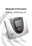
INSTALLATION
AND
SERVICE MANUAL
microprocessor-controlled system controller for solar-thermal systems:
SOLAREG II
VISION
IMPORTANT!
PLEASE, READ CAREFULLY THIS MANUAL BEFORE INSTALLATION AND USE OF THE
APPLIANCE!
NON-COMPLIANCE CAN RESULT IN GUARANTEE EXCLUSION!
KEEP THE MANUAL SAFE!
The described appliance has been made and tested in compliance with CE-guidelines.
1
2
Symbols and short descriptions.......................................................................................3
Range of application / characteristic features.................................................................4
2.1
2.2
2.3
3
4
Range of application ............................................................................................................. 4
Appliance characteristic features ........................................................................................ 4
System types for SOLAREG II VISION ................................................................................. 5
Safety instructions .............................................................................................................6
Appliance installation ........................................................................................................7
4.1
4.2
5
Opening of the appliance ..................................................................................................... 7
Wall installation..................................................................................................................... 7
Electrical connection - overview.......................................................................................8
5.1
230V-connections ......................................................................................................... 9
5.1.1
5.2
5.2.1
5.2.2
6
Overview: 230V-connections for SOLAREG II.....................................................................................10
Connection temperature sensor ........................................................................................ 10
Overview: sensor connections for SOLAREG II...................................................................................11
Overvoltage protector module..............................................................................................................11
Operation / Display...........................................................................................................12
6.1
6.2
6.3
6.4
6.5
7
Overview of display and operating elements.................................................................... 12
Display – maximal display .................................................................................................. 13
Explanation of graphic symbols ........................................................................................ 13
Button function ................................................................................................................... 15
Exemplary appliance operation.......................................................................................... 16
Operating menu................................................................................................................17
7.1
Overview: Construction of menu structure....................................................................... 18
7.2
Menu „Info“
7.3
Menu „Programming“
7.4
Menu „Manual operation“
............................................................................................ 20
7.5
Menu „Basic adjustment“
............................................................................................ 21
8
................................................................................................................... 19
.................................................................................................. 20
Controller functions .........................................................................................................22
8.1
General controller functions .............................................................................................. 22
8.1.1
8.1.2
8.1.3
8.1.4
8.1.5
8.1.6
8.2
System monitoring.............................................................................................................. 25
8.2.1
8.2.2
8.2.3
8.2.4
8.3
Sensor monitoring ................................................................................................................................25
Flow monitoring....................................................................................................................................25
Collector protection function / recooling ...............................................................................................26
System protection function...................................................................................................................26
Additional functions............................................................................................................ 27
8.3.1
8.3.2
9
Storage tank charge.............................................................................................................................22
Rotational speed regulation..................................................................................................................23
Cooling function ...................................................................................................................................23
Thermostat function (reheating)...........................................................................................................24
nd
2 temperature differential regulation..................................................................................................24
Tube collector function .........................................................................................................................25
Energy productivity measurement........................................................................................................27
Operating hours meter .........................................................................................................................27
Failure repair ....................................................................................................................28
9.1
9.2
10
11
12
13
14
Failures with error message............................................................................................... 28
Failures without error message ......................................................................................... 29
Technical data SOLAREG II .........................................................................................30
Resistance table PT1000..............................................................................................30
Table typical - current adjustments ............................................................................31
Terms of guarantee ......................................................................................................32
Declaration of conformity ............................................................................................32
1 SYMBOLS
AN D S H O R T D E S C R I P T I O N S
Explanation of graphic symbols used in the service manual:
Attention!
Symbol points out possible dangers and mistakes
Attention 230V-voltage!
Symbol points out the dangers through highly dangerous voltages.
•
Enumeration
Please, pay attention!
i
Information for operation / characteristic features
Realisation / procedure
?
Testing / checking
Often used abbreviations
In the following descriptions and in the controller display abbreviations or short symbols are partly used for simplification rea-
sons. Their meaning is presented in the following table.
Abbr.
Tcoll
Tst 1/2
Tret
Tth
Meaning
Temperature collector [°C]
Temperature storage tank [°C]
Collector return temperature [°C]
Temperature for thermostat [°C]
Abbr.
min
max
>
K
Tfr
xxx
h
Temperature antifreeze
Any display value
Operating hours
°C
dT
kWh
Meaning
Minimal value
Maximal value
bigger than
Kelvin Grade, corresponds to 1 grade
temperature difference
Celsius Grade
Temperature difference
Energy productivity in kWh
Tip: Put the enclosed with the appliance „Quick-Info“ into the pocket provided on the back of
the appliance to have always at hand an overview of all most important functions.
SOLAREG II VISION
Installation and service manual
2 R AN G E
O F AP P L I C AT I O N
F E AT U R E S
/
C H AR AC T E R I S T I C
2.1 Range of application
The solar thermal controllers SOLAREG II
VISION are powerful microprocessorcontrolled control appliances for functioncontrol of solar thermal systems.
SOLAREG II VISION regulates perfectly
thermal solar systems with up to 2 collectors
or 2 storage tanks and may be used for five
system types.
Controllers are planned for use in dry
spaces, in residential, business and industrial areas.
Wrong use has to be checked before starting by means of valid regulations.
2.2 Appliance characteristic features
The series SOLAREG II is provided with the
following outfit features:
• Intuitive, menu-conducted operation
with graphic symbols and four operating
keys.
• Temperature differential regulation digitally adjustable regulation values
• Rotational speed control or switch
control of solar circulation pump.
tivity measuring set (accessories) measures the energy obtained by a solar system.
• Storing of all adjusted values even in the
case of any longer mains voltage breakdown.
• Various protective functions, as e.g.
system protection, collector protection,
recooling and antifreeze
• Special function for systems with tube
collectors
• The third switch output for alternative
nd
choice of cooling function, heating or 2
temperature differential regulation
• Integrated operating hour meter for
storage tank charging
• Large wiring space
• Extensive functions for system monitoring with error and failure display through
symbols
Available accessories:
• Integrated energy productivity measurement which by means of the produc-
• Flow transmitter for productivity measurement
Service manual for SOLAREG II VISION
4
• Temperature sensor PT1000
1316BED002_11B-E,Release 11/2008
SOLAREG II VISION
Installation and service manual
2.3 System types for SOLAREG II VISION
Tip: the following system plans are no complete hydraulic wiring diagrams
TYPE 0:
1 collector, 1 storage tank
TYPE 1:
1 collector, 2 storage tanks
pump-valve
TYPE 2:
1 collector, 2 storage tanks
with 2 pumps
TYPE 3:
2 collectors, 1 storage tank
pump-valve
TYPE 4:
2 collectors, 1 storage tank
with 2 pumps
Tcoll
P
Temperature measuring
collector
Temperature measuring
thermostat
Temperature measuring
collector return
Temperature measuring
storage tank
Pump
FM
Flow meter
Tth
Tret
Tst
Service manual for SOLAREG II VISION
5
point
point
point
point
1316BED002_11B-E,Release 11/2008
SOLAREG II VISION
Installation and service manual
3 S AF E T Y
INSTRUCTIONS
All installation and wiring work at the controller must be carried out only in
an idle condition.
The connection and starting of SOLAREG II must be carried out only by a
competent staff. While doing this you have to keep to valid safety regulations, above all VDE 0100.
Disconnect the appliance from operating
voltage completely before any installation or wiring work at the electrical operating material.
Never mix-up the connections of protective low voltage area (sensor, flow
transmitter) with 230V-connections. Destruction and extremely dangerous voltage on the appliance and on the connected sensors and other appliances is
possible.
Solar systems can absorb high temperatures. There is a danger of burning! Be
careful during installation of the temperature sensor!
Mount SOLAREG II so that not to cause
inadmissible operating temperatures
(>50°C) for the appliance e.g. through
sources of heat.
Service manual for SOLAREG II VISION
6
SOLAREG II is neither splash-proof nor
drip-proof. And so mount it in a dry
place.
For safety’s sake the system can remain
in a hand mode only for test purposes.
In this operating mode neither maximal
temperatures nor sensor functions are
monitored.
If any damage on the controller, the cable or connected pumps and valves
have been detected, the system must
not be started.
Check if the materials used for tubing,
insulation as well as the pumps and
valves are suitable for existing temperatures in the system.
1316BED002_11B-E,Release 11/2008
SOLAREG II VISION
Installation and service manual
4 A P P L I AN C E
I N S T AL L AT I O N
The controller must be installed only in dry, no explosion-dangered places.
Installation on the combustible ground is not permissible.
4.1 Opening of the appliance
You do not need any tools to open the appliance. Upper part of the appliance housing
is bolted by means of two raster with a
lower part. In can be unlocked and opened
upwards through light pulling at the side
parts (straps) of the upper part of the appliance housing (see picture).
Keep opening the housing upper part so far
upwards until it is latched. Now you can
freely install and wire the controller.
Before starting shut the cover, please, until it is latched!
4.2 Wall installation
In the case of the wall installation proceed in the following way:
•
Drill installation holes accordingly to
the enclosed drilling jig
•
Screw in two upper screws up to 6
mm distance
•
Open the appliance as it is described
and hang it onto two screws. Now
two lower screws can be mounted.
•
126mm
84mm
Tighten all screws as firmly only
as it is really necessary in order to
avoid damages in the housing
lower part!
118mm
Service manual for SOLAREG II VISION
7
1316BED002_11B-E,Release 11/2008
SOLAREG II VISION
Installation and service manual
5 E L E C T R I C AL
CONNECTION
-
OVERVIEW
Please, absolutely follow safety instructions
in chapter 2
The appliance may be opened only when mains voltage has
been safely cut off and it is protected against restarting
The connection of all electrical wires takes
place on the compo entry in the housing
lower part. On the right compo entry side
there are (low voltage) connections for sen-
sors and flow transmitters. On the left side
there are 230V-connections. The following
picture shows the connection field of
SOLAREG II VISION.
FUSE
PE - PE A3 A2 A1 L1
S1 S2 S3 S4 S5 S6 S7
MMMMM MM
PE - PE N N N N
PE
Earthed wire
S7
Flow transmitter
L
Phase of mains
S1
Temp.- sensor collector 1
N
Zero wire of mains
S2
Temp.- sensor storage tank 1
A1
Phase switch output 1
S3
Temp.- sensor collector 2 / storage
tank 2
N
Zero wire switch output 1
S4
Temp.- sensor collector- return
A2
Phase switch output 2
S5
Temp.- sensor thermostat or for 2nd
temperature differential controller
N
Zero wire switch output 2
S6
Temp.- sensor antifreeze or for 2nd
temperature differential controller
A3
Phase switch output 3
N
Zero wire switch output 3
Service manual for SOLAREG II VISION
8
1316BED002_11B-E,Release 11/2008
SOLAREG II VISION
Installation and service manual
General connection rules:
In the case of all connecting wires skin a
cable covering ca. 6 - 8 cm long and the
ends of veins ca. 10 mm long.
In the case of flexible wires you must
have outside or inside the appliance a
pull-relief. The vein ends must be
equipped with wire end ferrules. In the
bushing nipples on the 230V-side you
can mount PG9 screwed connections if
necessary.
Cables are inserted in the appliance
through provided holes...
All earthed wires must be fixed in binders marked with „PE“ (potential earth).
5.1 230V-connections
For 230V-connections you must follow the
following points:
i
In the case of solid electric mains the
mains voltage for the controller outside
the controller must be able to be
switched off by a switch.
In the case of electric mains with the
help of cables and shock-proof plug this
switch may be left out.
Controllers are intended for the operation in 230V /50Hz mains. The pumps to
be connected and valves must be laid
for this voltage!
i
All switch outputs (A1/A2/A3) are
230V~ closers. If potential-free contacts
are needed, appropriate accessories
are available
i
Output A1 is operated, according to an
adjustment, as a closer (rotational
speed = 100%) or in the case of the
function „Rotational speed regulation“(rotational speed < 100%) with
block-modulated output signal for the
pump P1.
i
Output A2 behaves as A1 for pump P2
in system types Type 2 and Type 4. In
system types Type 1 and Type 3 a
valve V1 switched over.
i
Output A3 is planned for cooling, thermostat or for 2nd temperature differential controller function.
All earthed wires must be connected to
binders marked with PE.
Zero wire binders (N) are electrically
connected and are not switched!
Service manual for SOLAREG II VISION
9
1316BED002_11B-E,Release 11/2008
SOLAREG II VISION
Installation and service manual
5.1.1 Overview: 230V-connections for SOLAREG II
In the following table an assignment of
switch outputs for various controller types is
presented. Grey fields are absolutely nec-
essary for basic function of the system.
White fields are intended for optional additional functions.
System type
Type Description
A1
0
1 collector – 1 storage tank
P1
1
1 collector – 2 storage tank (pump valve)
P1
2
1 collector – 2 storage tank (pump pump)
P1
3
2 collector – 1 storage tank (pump valve)
P1
4
2 collector – 1 storage tank (pump pump)
P1
Switch outputs
A2
A3
cooling or thermostat
nd
or 2 diff. regulation
cooling or thermostat
V1
or 2nd diff. regulation
cooling or thermostat
P2
or 2nd diff. regulation
cooling or thermostat
V1
or 2nd diff. regulation
cooling or thermostat
P2
or 2nd diff. regulation
5.2 Connection temperature sensor
The appliances SOLAREG II work with precise platinum-temperature sensors type PT1000.
According to the controller type and function range you need from 2 to 4 sensors.
Installation / cabling of temperature sensors:
Mount the sensors in the provided places
in the collector and storage tank. Pay attention to a good temperature crossing
and use, if necessary, heat conducting
paste.
The wires of the temperature sensor can
be lengthened. Up to 15 m long you need
a 2 x 0,5mm² cross-section, up to 50 m 2
x 0,75 mm². In the case of long connec-
Service manual for SOLAREG II VISION
10
tions (collector) shielded extension lead
must
be
used.
On the sensor side do not pinch the
shield but cut off and isolate it!
Temperature sensors are connected according to the layout plan. Polarity of
both veins may be ignored in the case of
temperature sensors.
Sensor wires must be laid separately
from 230V-wires.
1316BED002_11B-E,Release 11/2008
SOLAREG II VISION
Installation and service manual
5.2.1 Overview: sensor connections for SOLAREG II
used for antifreeze or 2nd temperature differential controller, it may be used as a universal temperature sensor input. In this
case no sensor monitoring takes place.
In the following table the assignment of
sensor inputs is presented. Grey fields are
absolutely necessary for basic function of
the system. White fields are intended for
optional additional functions. If T6 is not
System type
Inscription on controller
Type Description
0
1
2
3
4
1 collector - 1 storage tank (pump)
1 collector - 2 storage tank (pump
valve)
1 collector - 2 storage tank (pump
pump)
2 collector - 1 storage tank (pump
valve)
2 collector - 1 storage tank (pump
pump)
1
2
3
4
Tcoll1
Tst1
-
Tret
Tcoll1
Tst1
Tst2
Tret
Tcoll1
Tst1
Tst2
Tret
Tcoll1
Tst1
Tcoll2
Tret
Tcoll1
Tst1
Tcoll2
Tret
5
Tth
TDiff1
Tth
TDiff1
Tth
TDiff1
Tth
TDiff1
Tth
TDiff1
6
Tfr
TDiff2
Tfr
TDiff2
Tfr
TDiff2
Tfr
TDiff2
Tfr
TDiff2
Before starting shut the cover until it is latched!
5.2.2 Over voltage protector module
SOLAREG II is equipped with an over voltage fine protector on all sensor inputs. Additional protection measures are not necessary as a rule for internal sensors. For collector sensor an additional protection (PROZEDA sensor connecting box with over
voltage protection) is recommended. External protection elements must not contain
any additional capacitors because they may distort measurement result.
Service manual for SOLAREG II VISION
11
1316BED002_11B-E,Release 11/2008
SOLAREG II VISION
Installation and service manual
6 O P E R AT I O N / D I S P L AY
6.1 Overview of display and operating elements
Number
1
2
3
4
5
Description
Display with graphic symbols
Control button scroll upwards / +
Control button exit / break-off
Control button scroll downwards / Control button choice / confirmation
Service manual for SOLAREG II VISION
12
1316BED002_11B-E,Release 11/2008
SOLAREG II VISION
Installation and service manual
6.2 Display – maximal display
In the following graphics there are all symbols which may appear during work on display, simultaneously presented. During a
real work, according to menu position, only
some of these symbols appear.
Main menu
Display values
Measuring points assignment
Status indication
6.3 Explanation of graphic symbols
In the following table the meaning of each symbol is described.
Graphic symbole
Description
Main menu
Indication in operation
Menu „Info“
Menu „Programming“
Symbol flashes, if possible to be chosen
Menu „Manual operation“
Menu „Basic adjustment“
During selection the active symbol flashes. If the menu is chosen by means of the
ton, a corresponding symbol is statically presented. All others fade out.
Service manual for SOLAREG II VISION
13
but-
1316BED002_11B-E,Release 11/2008
SOLAREG II VISION
Installation and service manual
Graphic symbole
dT
Description
Indication value
Temperature difference
Indication in operation
min
Min value
appears when minimal values are indicated
max
Max value
appears when maximal values are indicated
5 x 7 segment display
Presentation of figures 00000
to 99999
Issue of all figure values,
display flashes when a value is changed
Temperature in Celsius
Temperature difference in Kelvin
h
Operating hours
Productivity indication in kWh
Measuring points assignment
Temperature measuring point
collector1
Temperature measuring point
collector2
Temperature measuring point
storage tank 1 below (storage
tank charging)
Temperature measuring point
storage tank below (storage
tank charging)
Temperature measuring point
collector-return
Temperature measuring point
storage tank above (thermostat
function)
Antifreeze sensor or universal
temperature measuring point
(T6) (no sensor monitoring)
2nd temperature differential
controller
Operating hours, energy productivity measurement
Service manual for SOLAREG II VISION
14
1316BED002_11B-E,Release 11/2008
SOLAREG II VISION
Installation and service manual
Status indication
Solar circulation pump
symbol goes round when solar circulation pump is on
Switch output 1 is active
appears when switch output 1 active
(on)
Switch output 2 is active
appears when switch output 2 active
(on)
Switch output 3 is active
appears when switch output 3 active
(on)
Reference to system fault
display flashes when a fault occurs in
the system
Safety query for value changes
which are stored
Input value can be
3
!
ok?
rejected
or
accepted
6.4 Button function
Operation of the controller SOLAREG II
takes place comfortably and simply by
means of 4 operating buttons. By means of
operating buttons you can:
Graphic symbols of the display lead you in a
simple way through the operating structure
and show clearly the current menu points,
display values or parameters.
• recall display values
• carry out appliance adjustment
Operating buttons have the following functions:
Button
Function
„Up“
„+“
„Call“
„Down“
„-“
„Scroll left“
„Exit“
„Break-off“
„Scroll right“
„Choice“
„Confirmation“
Service manual for SOLAREG II VISION
Description
• Menu points upwards
• Value change: increase of the indicated value by 1
at longer pressing the values raise constantly
• Call up of main menu, menu points downwards
• Value change: decrease of the indicated value by 1 at
longer pressing the values decrease constantly
• In main menu scroll to the left
• Exit menu
• Exit menu point
• Break-off value change without storing
• In main menu scroll to the right
• Choosing one menu point
• Confirmation of value change with storing
15
1316BED002_11B-E,Release 11/2008
SOLAREG II VISION
Installation and service manual
6.5 Exemplary appliance operation
When you have read the descriptions of the
menu in chapter „Operating menu“, you can
practise operating steps. Below an operation example is presented. The current col-
White:
Grey:
Button
lector temperature is the starting position in
menu „Info“. Target: change of the parameter „Storage tank dToff“ from 3K to 4K in
menu „Programming“
Symbol static
Symbol flashes
Graphic indication after
Function
operation step
Description
„Exit“
Exit menu’s „Info“
„Scroll
right“
Choosing menu „Programming“
„Call“
max
65°C
„Down“
dT min
3K
Call up menu „Programming“,
the first menu point appears
Repeated pressing up to menu point „S1
dTmin„ appears.
„Choice“
dT min
3K
Choosing presented parameter
„Up“
dT min
4K
Increase of the parameter value from 3K to
4K
„Confirm“
„Confirm“
dT min
4K
ok?
dT min
4K
Confirmation of the parameter
Storing of the parameter
„Exit“
Exit menu „Programming“
„Scroll
left“
Choosing menu „Info“
„Call“
Service manual for SOLAREG II VISION
Call up menu „Info“
60°C
16
1316BED002_11B-E,Release 11/2008
SOLAREG II VISION
Installation and service manual
7 O P E R AT I N G
To make the operation of the appliance
clear, the appliance, operating and display
functions are divided into 4 groups (= main
menus).
Four menus
• Info
• Programming
Menu
Info
Programming
MENU
• Manual operation
• Basic adjustment
give you the information about your solar
system.
Each active menu is presented in the upper
line of the display through corresponding
graphic symbol.
Overview of contained functions
Main menu for automatic regulation of solar system.
• Indication of current measuring values
• Indication of system condition
• Indication of error messages
• Indication of operating hours and energy productivity (if available)
Change and adjustment of programmable desired values (parameters)
Hint: changes can affect system functions
Manual operation Switching on and off connected pumps / valves by hand
Basic adjustment Information about basic adjustment for system function.
Please, pay attention: adjustments and changes must be carried out only
by a specialist!
Service manual for SOLAREG II VISION
17
1316BED002_11B-E,Release 11/2008
SOLAREG II VISION
Installation and service manual
7.1 Overview: Construction of menu structure
The overview shows the whole menu structure. According to basic adjustment and system type
some menu points may be left out or shown alternatively („/“).
Info
Programming
Manual operation
Basic adjustment
I
Current temperature
Collector / Collector1
Minimal temperature
Collector / Collector1
Maximal temperature
Collector / Collector1
I
Maximal temperature
storage tank1
storage tank1
dTmax (dTon)
storage tank1
dTmin (dToff)
I
pump1 on / off
I
Collector protect. function
on / off
Collector protection
temperature
Recooling function
Current temperature
Maximal temperature
Storage tank1 below / Collector2
storage tank2
Minimal temperature
storage tank2
Storage tank1 below / Collector2
dTmax (dTon)
Maximal temperature
storage tank2
Storage tank1 below / Collector2
dTmin (dToff)
Current temperature
Minimal
Storage tank2 below / Stor. tank pump rotational speed in %
Minimal temperature
Thermostat function
Storage tank2 below / Stor. tank
Ton
Maximal temperature
Thermostat function
Storage tank2 below / Stor. tank
dT
nd
Current
2 temp.-diff. controller
Collector-return-temperature
Maximal temperature of
heat consumer
Tmax
nd
Current storage temperature
2 temp.-differential con(Storage tank above)
troller
/
Switching hysterisis
nd
2 temp. differential controller
dTmax
Temperature heat generator
Antifreeze sensor
/
nd
2 temp. differential controller
Temperature heat generator
/
Universal measuring point T6
Operating hours pump1
Energy productivity storage tank
Operating hours pump2
Energy productivity storage tank
Service manual for SOLAREG II VISION
18
pump1 / valve1
on / off
heating / cooling /
nd
2 diffcontr
on /off
Recooling
temperature
Tube collector
function
Energy productivity
measure on/off
Choosing used glycol
types
Mixture ratio
Glycol / water in %
Litres pro impulse of flow
meter
Switching on or off function antifreeze
Antifreeze function
temperature
Choice: cooling function,
thermostat function,
nd
2 temperature differential controller
System type
1316BED002_11B-E,Release 11/2008
SOLAREG II VISION
Installation and service manual
7.2 Menu „Info“
In this operational mode all measuring values and operating states are shown.
i
Only controller-specific values, as
well as those needed for activated
additional functions are shown!
If the values are marked as „reset able“, they may be reseted in the following way:
Choice of the value by means of buttons
and
Resetting of the value by means of the button
Message „OK?“ confirm with
= no or
Indication
= yes
Reset
possible
Meaning
e.g.
Indication of current collector temperature (1/2)
no
Indication of minimal collector temperature (1/2)
Reset able to current temperature
yes
Indication of maximal collector temperature (1/2)
Reset able to current temperature
yes
Indication of current temperature storage tank (1/2)
no
Indication of minimal temperature storage tank (1/2)
Reset able to current temperature
yes
Indication of maximal temperature storage tank (1/2)
Reset able to current temperature
yes
Antifreeze sensor
Indication of universal temperature measuring points (T6)
no
Indication of current temperature storage tank thermostat
no
60 °C
Indication of current temperature collector return
no
60 °C
2nd temperature differential controller
Temperature of heat generator
no
35 °C
2nd temperature differential controller
Temperature of heat consumer
no
1234 h
Operating hours for charging storage tank
Reset able to 0 h
yes
Energy productivity for storage tank
Reset able to 0 kWh
yes
75 °C
min
12 °C
max
105 °C
52 °C
min
40 °C
max
67 °C
25 °C
55 °C
927 kWh
Service manual for SOLAREG II VISION
19
1316BED002_11B-E,Release 11/2008
SOLAREG II VISION
Installation and service manual
7.3 Menu „Programming“
All changeable parameters can be checked
in this menu and, if necessary, changed. In
the factory-set-up usual values, which as a
rule guarantee problem-free function of the
system, are placed.
Indication
e.g.
The number of indicated values depends on
the controller type and the adjusted additional functions. Only the needed values are
shown at a time:
Value
range
Typical adjustment
15..95°C
65°C
Storage tank: switch-on difference (dTon)
3..40K
7K
Storage tank: switch-off difference (dToff)
2..35K
3K
Adjustment of minimal pump power at rotational speed regulation
100% = rotational speed regulation off
30%..100
%
100%
Switch-on temperature of thermostat function
20..90°C
40°C
1..30K
10K
15..95°C
65°C
3..40K
7K
Meaning
Storage tank:
Permissible maximal temperature
max
65 °C
dT max
7K
dT min
3K
min
100
2
40 °C
dT
Hysteresis of thermostat function
10 K
Max
65 °C
dT max
7K
nd
2 temperature difference controller: maximal
temperature of heat consumer Tmax
2nd temperature difference controller:
Hysteresis dTmax
7.4 Menu „Manual operation“
For service and test purposes the solar system can be operated by hand. For this purpose 230V switch outputs may be disconnected or connected. During manual operation there is no automatic regulation of the
system. To avoid inadmissible operating
states this mode of operation changes into
„Indication“ after ca. 8 hours and the automatic regulation is activated again.
Value
range
Meaning
Indication
Switching on / off switch output A1 (solar circulation pump) by hand
Service manual for SOLAREG II VISION
20
0 = off
1 = on
1316BED002_11B-E,Release 11/2008
SOLAREG II VISION
Installation and service manual
Switching on / off switch output A2 (pump2 / valve1) by hand
3
Switching on / off switch output A3 (cooling, thermostat or 2
perature difference controller function) by hand
nd
0 = off
1 = on
tem-
0 = off
1 = on
7.5 Menu „Basic adjustment“
Adjustments and changes in this menu must be carried out only by an installator or
competent staff. False adjustments may affect the function of controller and solar system.
To avoid accidental changes in menu „Basic
adjustment“, it is not editable in normal
functioning but has only display function. To
be able to carry out any changes, you
must choose this menu within the first
minute after switching on the appliance.
Indication
Then the possibility of time-unlimited editing
is given. The basic adjustment menu „is
blocked“ automatically within one minute after leaving or one minute after
switching on the appliance.
Meaning
Value range
0 = off
1 = on
110..150°C
Line / value
4 --
0
5 --
0
6 -7 --
0
100
Switching on or off function
collector protection
Temperature at which the collector protection function is active
Switching on or off function recooling
(only when the collector protection is on)
Temperature to which the storage tank is
recooled after active collector protection
function
Special function for time-controlled circulation in operation with tube collectors
Switching on or off function energy productivity measurement
Choosing used glycol types
Mixture ratio of coolants
8 --
10,0
Litres pro impulse of flowmeter
9 --
0
Switching on or off function antifreezing
10 --
-1 °C
11 --
0
Temperature at which antifreezing function is active
Alternative choice of cooling function,
thermostat function or the 2nd temperature difference controller
12 --
0
System type
0 --
0
1 -- 120 °C
2 -3 --
0
40 °C
Service manual for SOLAREG II VISION
21
Factory
set-up
0 = off
120°C
0 = off
1 = on
30..90°C
0 = off
0 = off
1 = on
0 = off
1 = on
0...9
0 ... 100%
5% - steps
0,5 … 25 l/I
0,5l - steps
0 = off
1 = on
-20 °C ... +7 °C
0 = off
0 = off
1 = cooling function
2 = thermostat function
3 = 2nd temperature
difference controller
0...4
0
40°C
0 = off
0
50
10,0
0
0
0
1316BED002_11B-E,Release 11/2008
SOLAREG II VISION
Installation and service manual
Glycol types corresponding to menu point 6:
0
1
2
3
4
Anro
Ilexan E, Glythermin
Antifrogen L
Antifrogen N
Ilexan E
8
5
6
7
8
9
Ilexan P
Tyfocor L5.5
Dowcal 10
Dowcal 20
Dowcal N
CONTROLLER
The controllers SOLAREG II contain many
functions to regulate and monitor solar system. Basically you can distinguish
FUNCTIONS
• functions for system protection and system monitoring
• additional functions.
• controller functions for charging a storage
tank
8.1 General controller functions
The controller collects the temperatures of
various measuring points and determines
the right time to charge the storage tank on
account of programmed (additional) functions and controller parameters.
8.1.1 Storage tank charge
Corresponding values in menu
„Basic adjustment“:
„Programming“
--Maximal temperature
--dT max (dTon)
Switch-on temperature difference
--dT min (dToff)
Switch-off temperature difference
The storage tank is being charged through
the pump on output A1 (A2) up to adjusted
maximal temperature so long as the collector temperature becomes higher by a cer.
Service manual for SOLAREG II VISION
22
tain amount than the storage tank temperature. Switching action can be adjusted
through dTmax (dTon) and dTmin (dToff),
but dTon cannot get lower than dToff + 1K
1316BED002_11B-E,Release 11/2008
SOLAREG II VISION
Installation and service manual
Storage tank charge
T[°C]
max
65 °C
dTmin
Tst
dTmax
A1
On
Off
pump on
(A1)
8.1.2 Rotational speed regulation
Corresponding values in menu
„Basic adjustment“:
„Programming“
--Rotational speed min <100%
The solar circulation pumps on 230Voutputs A1 and A2 can be operated either
in switch-mode (two-point controller) or in a
rotational speed regulated way.
If the rotational speed regulation is activated the pump power is adjusted by a controller so that switch-on temperature differ-
ence „Storage tank dTmax“ is kept constant
as much as possible. At lower deviation of
„Storage tank dTmax“the pump is operated
with the lowest power till the switch-off wave
is reached.
8.1.3 Cooling function
Corresponding values in menu
„Basic adjustment“:
„Programming“
11 -1
--To increase the energy productivity of solar
system it may be useful to „by-pass“the solar energy at reaching a certain storage tank
temperature or to take it from the storage
tank. If the temperature of the storage tank
(Tst) goes over the temperature barrier
Tstmax – 5K (adjusted maximal storage
tank temperature – 5K), the switch output
A3 is switched on. Switching off takes place
at lower deviation of this temperature.
23
1316BED002_11B-E,Release 11/2008
Service manual for SOLAREG II VISION
SOLAREG II VISION
Installation and service manual
8.1.4 Thermostat function (reheating)
Corresponding values in menu
„Basic adjustment“:
„Programming“
11 -2
Thermostat Ton (Tth)
---
Thermostat dT
The thermostat function is a control circuit
dependant of storage charge. In this way
e.g. the reheating of the upper stand-by part
of the storage tank independent of solar circulation function is enabled.
T[°C]
Switch output A3 is
• switched on when the adjusted temperature „Thermostat Ton“ (Tth) remains under
• switched off when the adjusted temperature „Tth + dT“remains over.
Thermostat
(Storage tank above)
dT
10 K
Tth
40 °C
t
on
A2
off
8.1.5 2nd temperature differential regulation
Corresponding values in menu
„Basic adjustment“:
„Programming“
11 -3
Tmax (R2 max)
dTmax (R2 dT max)
nd
The 2 temperature difference regulation
enables you, independently of all other control functions, to control an output according
to an adjustable temperature difference criterion. TDiff1 is the temperature of a heat
generator and TDiff2 of a heat consumer.
The output is switched on when TDiff1 >=
TDiff2 + Diff.dTmax and simultaneously
TDiff2 < Diff.Tmax. It is switched off when
TDiff1 < TDiff2 + Diff.dTmax/2 or TDiff2 >
Diff.Tmax.
For this controller function you need temperature sensor inputs for antifreezing and
thermostat function or the 3rd switch output A3. For this reason the controller functions can be only alternatively chosen.
Service manual for SOLAREG II VISION
24
1316BED002_11B-E,Release 11/2008
SOLAREG II VISION
Installation and service manual
8.1.6 Tube collector function
Corresponding values in menu
„Basic adjustment“:
„Programming“
4 -1
--The function „Tube collector“is switched on
or off in menu Basic adjustments. If the
function is activated a circulation of heat
carrying medium through the collector takes
place for 30 seconds every 30 minutes. It is
necessary to be able to measure a temperature change in the collector when no
regulation-conditioned circulation has taken
place for a longer time.
Indication
Meaning
Short circuit on temperature sensor of the current measuring point
Break on temperature sensor of the current measuring point,
Circulation error at activated energy productivity measurement
8.2 System monitoring
In the case of an error the flashing symbol
!
is shown as a rule.
8.2.1 Sensor monitoring
The sensors necessary for control functions and their connecting cables are monitored regarding break and short circuit. If a faulty sensor is recognised by Software, the symbol
shown. By scrolling up and down you can find an error source.
!
is
Usage of false temperature sensors can lead to error message, too.
8.2.2 Flow monitoring
Indication
Meaning
+ !
Missing circulation in solar circuit
If the option energy productivity measurement is disactivated, the temperature difference between collector and storage tank is
Service manual for SOLAREG II VISION
25
checked.
If it exceeds the amount of (60K + dTmax),
1316BED002_11B-E,Release 11/2008
SOLAREG II VISION
Installation and service manual
it is then interpreted as an error because in
the case of normal system dimensioning
and a pump switched on such big differences cannot take place.
If the option energy productivity measurement is activated, the flow amount at the
pump switched on is checked. If for 15 minutes no flow is recognised it is evaluated as
an error.
Error message is automatically reseted after
eliminating the failure.
8.2.3 Collector protection function / recooling
Corresponding values in menu
„Basic adjustment“:
„Programming“
0 -1
--1 -- 120 °C
2 -1
3 -- 40 °C
(see 7.5)
The function is in menu basic adjustments
switched on or off.
Glycol mixtures can decompose in certain
conditions at high temperatures. Therefore
the maximal temperature should be limited
if possible in the collector circuit.
If all storage tanks are charged up to Tmax.,
the solar circulation pump is cut off. If the
collector temperature exceeds the adjusted
value „T Kollektor max.“, the solar circulation pump is being switched on until the collector temperature is reduced by 10K. A
part of energy is given away through pipelines as a waste, the rest is charged in the
storage tank which leads to the increase of
.
the storage tank temperature over the adjusted maximal temperature. For safety reasons the function is finished when the storage tank has achieved 95°C.
If the collector temperature falls by 2K under Tst, the recooling function becomes active. The excess storage tank energy is
given away again through the collector so
that at the next charging cycle new reserves
are available again. The recooling is finished when Tst falls under the adjusted
value Tst max.
The recooling function can be switched on
only when the collector protection function
is on.
8.2.4 System protection function
The system protection function switches off
the system at the temperature exceed „T
collector max.“ (see 8.2.3) + 10 K. This
function comes into effect no matter if the
Service manual for SOLAREG II VISION
26
collector protection is activated or not. As
soon as the temperature falls below this
value the system is started again.
1316BED002_11B-E,Release 11/2008
SOLAREG II VISION
Installation and service manual
8.3 Additional functions
8.3.1 Energy productivity measurement
Corresponding values in menu
„Programming“
---
„Basic adjustment“:
5 -1
For energy productivity measurement you
need additionally a flow meter and a
PT1000-sensor to measure the collector
return temperature Tret.
Energy productivity of the solar system is
calculated on the basis of the temperature
„Info“
xxxx kWh
difference between collector and collector
return temperature and the measured flow
quantity.
The function is switched on or off in menu
„Basic adjustments“.
8.3.2 Operating hours meter
Corresponding values in menu
„Programming“
---
„Info“
xxxx h
So long as the storage tank is charged by a
pump, the operating hours meter runs along
for each separate pump. The number of
operating hours can be read in menu
„Info“and for each pump separately reseted
to 0.
27
1316BED002_11B-E,Release 11/2008
Service manual for SOLAREG II VISION
SOLAREG II VISION
Installation and service manual
9 F AI L U R E
R E P AI R
In the case of system failures you must basically distinguish two categories:
• failures which can be recognised by the controller itself and therefore can be indicated
• failures which cannot be indicated by the controller
9.1 Failures with error message
Error representation on
display
!
possible reasons
Measures
• sensor wire broken
• sensor defect
check wire
check sensor resistance, if necessary exchange sensor
flashing
• short circuit in sensor
wire
• sensor defect
check wire
• error in pump connection
• pump defect
• air in the system
• flow meter defect
check cabling
!
flashing
Circulation error:
no flow
+ !
flashing
Additionally at energy
productivity measurement:
Service manual for SOLAREG II VISION
• connection with flow
meter defect
• sensor wire broken
• sensor defect
28
check sensor resistance, if necessary exchange sensor
exchange pump
deaerate the system
check if an impeller of the meter
moves when the system runs (if
visible)
check wire
check wire
check sensor resistance, if necessary exchange sensor
1316BED002_11B-E,Release 11/2008
SOLAREG II VISION
Installation and service manual
9.2 Failures without error message
You can check failures and malfunctioning,
which are not indicated, and find their error
sources according to the following table.
If failure repair is not possible on the basis
of the description you must ask the deliverers or installer.
Error presentation
No display function
Possible reasons
Measures
• 230V-mains voltage not switch on or connect the collector
check house safety fuse for the
existing
connection
check safety fuse, replace it by a
• appliance-internal
new one, type 2A/T, if necessary.
safety fuse defect
check 230V components on short
circuit
consult with the deliverers
• appliance defect
Controller does not work • controller is in manual exit menu „Manual operation“.
operation
• switch-on condition not wait until the switch-on condition is
fulfilled
fulfilled.
Symbol „Pump“ rotates,
check cable to pump
• pump connection brobut pump does not work
ken.
make the pump run well
• pump is fixed.
consult with the deliverers.
• no voltage on switch
output.
Temperature display var- • sensor wires laid near lay sensor wires differently
ies strong in short time
shield sensor wires
230V-wires
intervals
• long sensor wires
shield sensor wires
lengthened without
shielding
• appliance defect
consult with the deliverers
Service manual for SOLAREG II VISION
29
1316BED002_11B-E,Release 11/2008
SOLAREG II VISION
Installation and service manual
10
T E C H N I C AL
D AT A
SOLAREG II
Housing
Material
100% recyclable ABS-housing for wall installation
Measures L x W x D in mm, 175 x 134 x 56; ca. 360 g
weight
System of protection
IP20 according to VDE 0470
Electrical values
Operating voltage
AC 230 Volt, 50 Hz, -10...+15%
Interference grade
N according to VDE 0875
Max. conductor cross-section
230V-connections
2,5 mm² fine-strand/single-wire
Temperature sensor / temperature range
PTF6 - 25°C - 200°C
PT1000, 1,000 kΩ at 0°C
Testing voltage
Switching voltage
Capability per one switch output
Total capability of all outputs
4 kV 1 min according to VDE 0631
230V∼ /
1A / ca. 230VA for cos ϕ = 0,7-1,0
2A / ca. 460VA maximal
Fuse protection
fine-wire fuse 5 x 20mm, 2A/T (2 amperes, slow)
Others
Recommended flow transmitter
PVM 1,5/90 1500l/h, Tmax >=90°C, 10l/impuls
Operating temperature
0 ... + 50°C
Storing temperature
-10 ... + 65°C
Changes for technical purposes reserved!
11 R E S I S T AN C E
T AB L E
PT1000
The correct function of temperature sensors can be checked on the basis of the following temperature resistance table with a resistance measuring instrument:
Temperature
in °C
-30
-20
-10
0
10
20
30
40
50
Service manual for SOLAREG II VISION
Resistance
in Ohm
882
921
960
1000
1039
1077
1116
1155
1194
Temperature
in °C
60
70
80
90
100
120
140
200
30
Resistance
in Ohm
1232
1271
1309
1347
1385
1461
1535
1758
1316BED002_11B-E,Release 11/2008
SOLAREG II VISION
Installation and service manual
12 T AB L E
T Y P I C AL
-
C U R R E N T AD J U S T M E N T S
Adjustments in menu „Programming“
Storage tank1: permissible maximal temperature
Storage tank1: switch-on difference (dTon)
Storage tank1: switch-off difference (dToff)
Storage tank2: permissible maximal temperature
Storage tank2: switch-on difference (dTon)
Storage tank2: switch-off difference (dToff)
Minimal pump power at rotational speed regulation
Switch-on temperature of thermostat function
Hysteresis of thermostat function
2nd temperature differential controller maximal temperature
Tmax
2nd temperature differential controller hysteresis dTmax
Adjustments in menu „Basic adjustment“
Switching on or off the function collector protection
Temperature at which the collector protection function is
active
Switching on or off the function recooling (only when the
collector protection is on)
Temperature to which the storage tank is recooled after
the active collector protection function
Special function for time-controlled circulation in operation
with tube collectors
Switching on or off the function energy productivity measurement
Alternative choice of the cooling function or the thermostat
function
Choice of glycol types used
Typical adjustment
65 °C
7K
3K
90 °C
7K
3K
100 %
40 °C
10 K
65 °C
7K
Typical adjustment
Current adjustment
0 = off
120 °C
0 = off
40 °C
0 = off
0 = off
0 = off
0 = Anro
Mixture ration of coolants
50 %
Litres pro impulse of the flowmeter
10,0 L/I
Switching on or off the function
antifreezing
0 = off
Temperature at which the antifreezing is active
-1 °C
Alternative choice of the cooling, thermostat function or the
2nd temperature differential controller
System type
Service manual for SOLAREG II VISION
Current adjustment
0 = none
type 0
31
1316BED002_11B-E,Release 11/2008
SOLAREG II VISION
Installation and service manual
13 T E R M S
O F G U AR AN T E E
The controlling appliances SOLAREG II are carefully produced and checked at an automatic
test place. Should any failures occur, check first if there are any operation / adjustment or system error. Furthermore the pump and temperature sensor connections are to be checked.
PROZEDA GmbH provides a guarantee according to the following terms for 24 months beginning from the purchase date.
a) The guarantee takes place in the case of existing material defect of the purchased good. If
this defect is due to an operating error, exceeding the permissible technical data, false wiring, not permissible technical changes in the appliance made by the customer or other company than ROZEDA GmbH, no guarantee is provided.
b) The guarantee requires a notification in writing which describes the defect in detail and
a copy of a customer´s invoice.
The guarantee takes place according to the free choice of PROZEDA GmbH through
- repair (improvement) or
– delivery of functioning spare part
The maximum repair period is 1 month with effect from receipt of the appliance by
PROZEDA GmbH.
If two repair attempts go wrong, the customer has the right to the claim to the delivery of
functioning spare part.
In the case of delivery of a spare part a new guarantee meeting these terms comes into effect.
c) Any further warranty (exchange, price reduction) is excluded.
Guarantee claims are entitled only to the customer and are not transferable.
In the case of defects within the guarantee time communicate first with the deliverers / installators. In the case of returns you always have to enclose error description, if possible the appliance plan and wiring plan.
14 D E C L AR AT I O N
OF CONFORMITY
The described appliance has been made and tested in compliance with CE-guidelines.
Service manual for SOLAREG II VISION
32
1316BED002_11B-E,Release 11/2008