1
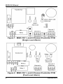
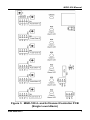
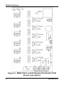
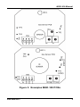
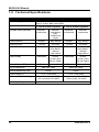
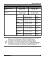
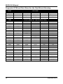
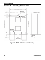
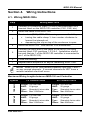
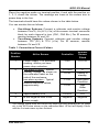
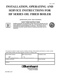
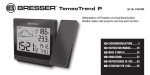
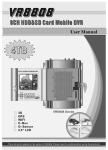
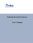
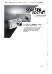
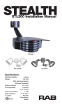
Gas Detector and Controllers
Installation and Operation Manual
Instruction 6109-9000
Revision 3 – June 2013
Product Leadership • Training • Service • Reliability
MGD-100 Manual
WARRANTY POLICY
BACHARACH, INC. WARRANTS THIS INSTRUMENT, EXCLUDING SENSORS, TO BE
FREE FROM DEFECTS IN MATERIALS AND WORKMANSHIP FOR A PERIOD OF TWO
YEARS FROM THE DATE OF PURCHASE BY THE ORIGINAL OWNER. THE SENSORS
HAVE A WARRANTY PERIOD OF ONE YEAR FROM THE DATE OF PURCHASE. IF
THE PRODUCT SHOULD BECOME DEFECTIVE WITHIN THIS WARRANTY PERIOD,
WE WILL REPAIR OR REPLACE IT AT OUR DISCRETION.
THE WARRANTY STATUS MAY BE AFFECTED IF THE INSTRUMENT HAS NOT BEEN
USED AND MAINTA INED PER THE INSTRUCTIONS IN THIS MANUAL OR HAS BEEN
ABUSED, DAMAGED, OR MODIFIED IN ANY WAY. THIS INSTRUMENT IS ONLY TO BE
USED FOR PURPOSES STATED HEREIN. THE MANUFACTURER IS NOT LIABLE FOR
AUXILIARY INTERFACED EQUIPMENT OR CONSEQUENTIAL DAMAGE.
DUE TO ONGOING RESEARCH, DEVELOPMENT, AND PRODUCT TESTING, THE
MANUFACTURER RESERVES THE RIGHT TO CHANGE SPECIFICATIONS WITHOUT
NOTICE. THE INFORMATION CONTAINED HEREIN IS BASED ON DATA CONSIDERED
ACCURATE. HOWEV ER, NO WARRANTY IS EXPRESSED OR IMPLIED REGARDING
THE ACCURACY OF THIS DATA.
ALL GOODS MUST BE SHIPPED TO THE MANUFACTURER BY PREPAID FREIGHT.
ALL RETURNED GOODS MUST BE PRE-AUTHORIZ ED BY OBTAINING A RETURN
MERCHANDISE AUTHORIZATION (RMA) NUMBER. CONTACT THE MANUFACTURER
FOR A NUMBER AND PROCEDURES REQUIRED FOR PRODUCT TRANSPORT.
SERVICE POLICY
BACHA RA CH, INC. MA INTA INS A N INSTRUMENT SERV ICE FACILITY AT THE
FA CTORY. SOME BA CHA RACH DISTRIBUTORS / AGENTS MAY ALSO HAV E
REPA IR FACILITIES, HOWEV ER, BACHA RA CH ASSUMES NO LIA BILITY FOR
SERV ICE PERFORMED BY ANYONE OTHER THA N BA CHA RACH PERSONNEL.
REPA IRS ARE WA RRA NTED FOR 90 DAYS AFTER DATE OF SHIPMENT
(SENSORS,
PUMPS,
FILTERS
AND BA TTERIES
HAV E
INDIV IDUAL
WARRA NTIES) . SHOULD YOUR INSTRUMENT REQUIRE NON- WA RRA NTY
REPA IR, YOU MAY CONTA CT THE DISTRIBUTOR FROM WHOM IT WAS
PURCHASED OR YOU MAY CONTA CT BA CHA RA CH DIRECTLY.
IF BA CHA RACH IS TO DO THE REPA IR WORK, SEND THE INSTRUMENT,
PREPA ID, TO BACHA RA CH, INC. A T THE FOLLOWING A DDRESS.
BACHA RA CH, INC.
621 HUNT VALLEY CIRCLE
NEW KENSINGTON, PA 15068
ATTENTION: SERV ICE DEPA RTMENT
ALWAYS INCLUDE Y OUR RMA #, ADDRESS, TELEPHONE NUMBER, CONTA CT
NA ME, SHIPPING/BILLING INFORMA TION AND A DESCRIPTION OF THE
DEFECT AS YOU PERCEIV E IT. YOU WILL BE CONTA CTED WITH A COST
ESTIMA TE FOR EXPECTED REPA IRS PRIOR TO THE PERFORMA NCE OF A NY
SERV ICE WORK. FOR LIA BILITY REASONS, BA CHA RACH HA S A POLICY OF
2
6109-9000 Rev 3
MGD-100 Manual
PERFORMING ALL NEEDED REPA IRS TO RESTORE THE INSTRUMENT TO
FULL OPERA TING CONDITION.
PRIOR TO SHIPPING EQUIPMENT TO BA CHA RA CH, CONTA CT OUR OFFICE
FOR A N RMA # ( RETURN ED MERCHA NDISE A UTHORIZATION). ALL RETURNED
GOODS M UST BE A CCOMPA NIED WITH AN RMA NUMBER.
PA CK THE EQUIPMENT WELL (IN ITS ORIGINAL PA CKING IF POSSIBLE), AS
BACHA RA CH CA NNOT BE HELD RESPONSIBLE FOR A NY DA MA GE INCURRED
DURING SHIPPING TO OUR FA CILITY.
NOTICES
COPY RIGHTS: THIS MA NUAL IS SUBJECT TO COPY RIGHT PROTECTION; ALL
RIGHTS ARE RESERV ED UNDER INTERNA TIONAL AND DOMESTIC
COPY RIGHT LAWS. THIS MA NUAL MAY NOT BE COPIED OR TRA NSLATED, IN
WHOLE OR IN PA RT, IN ANY MANNER OR FORMA T, WITHOUT THE WRITTEN
PERMISSION OF BA CHARA CH, INC.
ALL SOFTWARE USED AND/OR DISTRIBUTED BY BACHA RA CH IS SUBJECT TO
COPY RIGHT PROTECTION. ALL RIGHTS A RE RESERV ED. NO PA RTY MAY USE
OR COPY SUCH SOFTWA RE IN A NY MA NNER OR FORMA T, EXCEPT TO THE
EXTENT THA T BA CHA RA CH GRANTS THEM A LICENSE TO DO SO. IF THIS
SOFTWA RE IS BEING LOA DED ONTO MORE THA N ONE COMPUT ER, EXTRA
SOFTWA RE LICENSES MUST BE PURCHA SED.
TECHNICIAN USE ONLY
THIS UNIT MUST BE INSTALLED BY A SUITA BLY QUALIFIED TECHNICIA N WHO
WILL INSTALL THIS UNIT IN A CCORDA NCE WITH THESE INSTRUCTIONS A ND
THE STA NDA RDS IN THEIR PA RTICULAR INDUSTRY/COUNTRY. OPERA TORS
OF THE UNIT SHOULD BE AWA RE OF THE REGULA TIONS A ND STA NDA RDS IN
THEIR INDUSTRY/COUNTRY FOR THE OPERA TION OF THIS UNIT. THESE
NOTES A RE ONLY INTENDED AS A GUIDE A ND THE MA NUFA CTURER BEA RS
NO RESPONSIBILITY FOR THE INSTALLA TION OR OPERA TION OF THIS UNIT.
FA ILURE TO INSTALL AND OPERA TE THE UNIT IN A CCORDA NCE WITH THESE
INSTRUCTIONS AND WITH INDUSTRY GUIDELINES MAY CAUSE SERIOUS
INJURY INCLUDING DEA TH A ND THE MA NUFA CTURER WILL NOT BE HELD
RESPONSIBLE IN THIS REGA RD.
6109-9000 Rev 3
3
MGD-100 Manual
Table of Contents
SECTION 1.
OVERVIEW..............................................................................................5
1.1. General Information.......................................................................................... 5
1.2. Technical Specifications..................................................................................10
SECTION 2.
2.1.
2.2.
2.3.
2.4.
2.5.
2.6.
PLACING SENSORS ..............................................................................13
Installation Warnings ......................................................................................13
General Guidelines ..........................................................................................13
Machinery Rooms ............................................................................................15
Refrigerated Spaces.........................................................................................16
Chillers ...............................................................................................................16
Air Conditioning (Direct Systems VRF/VRV)................................................17
SECTION 3.
HOUSING DIMEN SIONS .....................................................................18
SECTION 4.
WIRING INSTRUCTIONS.....................................................................23
4.1.
4.2.
4.3.
4.4.
Wiring MGD-100s ...........................................................................................23
External Audible Alarm and DC Output .......................................................24
Relays .................................................................................................................25
Power Connection ...........................................................................................25
SECTION 5.
OPERATION AND STABILIZATION ....................................................31
SECTION 6.
FUNCTIONAL TESTS AND CALIBRATION.........................................33
6.1.
6.2.
6.3.
6.4.
6.5.
6.6.
6.7.
6.8.
6.9.
Introduction......................................................................................................33
Electrical Reset of One-Alarm Systems ........................................................35
Electrical Reset of Two-Alarm Systems........................................................36
Bump Testing ....................................................................................................37
Calibration Overview.......................................................................................40
Calibration Options..........................................................................................40
Sensor Board Exchange ..................................................................................40
On-Site Gas Calibration (One-Alarm Unit)...................................................41
Gas Calibration (Two-Alarm Units)...............................................................43
SECTION 7.
TROUBLESHOOTIN G...........................................................................44
DECLARATION OF CONFORMITY................................................................................47
4
6109-9000 Rev 3
MGD-100 Manual
Section 1. Overview
1.1. General Information
The MGD-100 is the ideal gas detection solution for installations
requiring a quality and affordable stand-alone gas detector. It consists of
1 to 6 remote gas sensors connected to and powered by a controller.
The controller provides visual, audible, and relay alarms on t he detection
of gases. The system is available with one or two levels of alarm.
The MGD-100 can be used for:
•
•
•
detecting refrigerant gases (including NH3 and CO2)
speedy detection of combustible gases
detection of toxic and VOC gases.
A range of gas detector and sensor enclosures are available for special
applications.
The MGD-100 Cont roller is required. With the MGD-100, it creates a
stand-alone gas detection system and is used to remotely monit or up to
six MGD-100 devices. Models are available with 1, 2, 4, and 6 channels.
Wiring diagrams are provided later in this manual.
6109-9000 Rev 3
5
MGD-100 Manual
Figure 1. MGD-100 1- and 2-Channel Controller PCB
(Single Level Alarm)
Figure 2. MGD-100 1- and 2-Channel Controller PCB
(Dual Level Alarm)
6
6109-9000 Rev 3
MGD-100 Manual
Figure 3. MGD-100 4- and 6-Channel Controller PCB
(Single Level Alarm)
6109-9000 Rev 3
7
MGD-100 Manual
Figure 4. MGD-100 4- and 6-Channel Controller PCB
(Dual Level Alarm)
8
6109-9000 Rev 3
MGD-100 Manual
Figure 5. Examples MGD-100 PCBs
6109-9000 Rev 3
9
MGD-100 Manual
1.2. Technical Specifications
Specification
Pow er Supply
Audible Alarm (Buzzer)
Alarm Silence
Description
120 VAC 60 Hz, 220 VAC 50 Hz, or 12 VDC (specif ied at
time of order); Max power 20W
1- and 2-channel systems
4- and 6-channel systems
Internal,
continuous
Internal,
intermittent
(low),
continuous
(high)
External,
continuous
External,
continuous
Jumper
Key Sw itch
Jumper
Key Sw itch
Alarm Levels
1 Level
2 Levels
1 Level
2 Levels
Alarm Reset
Automatic
Automatic
(low alarm),
manual
(high alarm)
Automatic
Automatic
(low alarm),
manual
(high alarm)
Alarm Delay
Selectable
Preset
25 sec (low)
30 sec (high)
Selectable
Preset
25 sec (low)
30 sec (high)
Red
Yellow, Red
Red
Yellow, Red
Visual Alarm LED(s)
Fault Indications
Pow er Monitoring LED
Alarm Relay(s)
Communications Wiring
Warm-up Delay
10
Red LED, relay
Red LED, relay
Green
Green
10 A, 120V/230V
10 A, 120V/230V
4-conductor cable, 200 ft
(61 m) max w / 22 AWG
4-conductor cable, 500 ft
(152 m) max, 22 AWG
Minimum of 3 minutes
6109-9000 Rev 3
MGD-100 Manual
Specification
Description
1- and 2-channel systems
4- and 6-channel systems
MGD-100: IP41
Controller: IP51
MGD-100: IP41
Controller: IP51
8.4” x 4.1” x 3.15”
214 x 105 x 80 mm
2.9 lbs / 1.3 kg
10.3” x 10.4” x 303”
262 x 265 x 84 mm
5.7 lbs / 2.6 kg
Standard Enclosure
Ratings
Dimensions and Weight:
Controller
Dimensions and Weights
IP41
3.35” x 5.59” x 2.09”
86 x 142 x 53 mm
6.3 oz
180 g
IP66
6.89” x 6.5” x 3.29”
175 x 165 x 82 mm
1 lb 6 oz
629 g
IP66 w / Splash
Guard
6.89” x 8.9” x 3.29”
175 x 225 x 82 mm
1 lb 9 oz
700 g
IP66 w /
Remote Sensor
6.89” x 6.1” x 3.29”
175 x 155 x 82 mm
1 lb 11 oz
790 g
IP66 w / Exd
Remote Head
6.89” x 6.1” x 3.29”
175 x 155 x 82 mm
2 lb 10 oz
1185 g
IP66 w / PRV
Sensor Head
6.89” x 6.1” x 3.29”
175 x 155 x 82 mm
2 lb 0.3 oz
916 g
IP66 Airflow/
Duct (See
Table)
6.89” x 4.9” x 3.29”
175 x 125 x 82 mm
1 lb 4 oz
578 g
Exd (ATEX
only)
5.12” x 6.3” x 3.54”
130 x 160 x 90 mm
9 lb 4 oz
4200 g
NOTE: The haz ardous area Exd Gas Monitor products are
designed wit h individually certified Exd main housing
enclosures and certified Exd remote or attached sens or
enclosures. The main housing enclosure and its PCB
assembly are als o Exd certified, but the final Exd Gas Monitor
assemblies (main enclosure and/or sensor assembly) are not
currently Exd certified, but are pending additional testing.
6109-9000 Rev 3
11
MGD-100 Manual
Supported CFM and Duct Sizes for the Duct Mount Housing
Units
Duct Size
Inches
12 x 12
12 x 24
18 x 18
24 x 24
24 round
Feet
1x1
1x2
1.5 x 1.5
2x2
Pi x 1 x 1
Area (ft 2)
1
2
2.25
4
3.14
CFM
12
Ft/min (Based on CFM and Duct Size)
2800
2800
n/a
n/a
n/a
n/a
3000
3000
n/a
n/a
n/a
n/a
3400
3400
n/a
n/a
n/a
n/a
3800
4000
3800
4000
n/a
n/a
n/a
n/a
n/a
n/a
n/a
n/a
4400
4400
n/a
n/a
n/a
n/a
4800
4800
n/a
n/a
n/a
n/a
5000
5000
2500
n/a
n/a
n/a
5400
5800
5400
5800
2700
2900
n/a
2578
n/a
n/a
n/a
n/a
6000
6000
3000
2667
n/a
n/a
6400
6400
3200
2844
n/a
n/a
6800
6800
3400
3022
n/a
n/a
7000
7400
7000
7400
3500
3700
3111
3289
n/a
n/a
n/a
n/a
7800
7800
3900
3467
n/a
n/a
8000
8000
4000
3556
n/a
2548
8400
8400
4200
3733
n/a
2675
8800
9000
8800
9000
4400
4500
3911
4000
n/a
n/a
2803
2866
9400
9400
4700
4178
n/a
2994
9800
9800
4900
4356
n/a
3121
10000
10000
5000
4444
2500
3185
6109-9000 Rev 3
MGD-100 Manual
Section 2. Placing Sensors
2.1. Installation Warnings
NOTE: This instrument can be equipped with a semiconductor
sensor for the detection of refrigerant, combustible and VOC
gases. Semiconductor sensors are not gas specific and respond
to a variety of other gases including propane exhaust, cleaners,
and solvents. Changes in temperature and humidity may also
affect the sensor’s performance.
WARNI NG: Explosion hazard! Do not mount the MGD-100 in
an area that may contain flammable liquids, vapors, or
aerosols. Operation of any electrical equipment in such an
environment constitutes a safety hazard.
CAUTION: The MGD-100 contains sensitive electronic
components that can be easily damaged. Do not touch nor
disturb any of these components.
NOTE: The mounting location of the monitor should allow it to
be easily accessible for visual monitoring and servicing.
NOTE: The monitor must be connected by a marked, suitably
located and easily reached switch or circuit-breaker as means
of disconnection.
NOTE: Connect monitor power and signaling terminals using
wiring that complies wit h local electrical codes or regulations
for the intended application.
2.2. General Guidelines
NOTE: The MGD-100 should be installed plumb and level
and securely fastened to a rigid mounting surface.
The MGD-100 cont roller and its sensor(s) should be positioned carefully
to avoid mechanical damage (from moving machinery, doors, etc.) and
thermal extremes (close to heaters). Units should not be placed
unprotected in direct strong drafts/airflows and areas where water or
moisture is pres ent unless an appropriate enclosure is used.
6109-9000 Rev 3
13
MGD-100 Manual
A void routing sensor c abling outside of premises, or between buildings
via overhead cables. Also, sensor wiring should be kept to a minimum of
20 in (500mm) from the main power supply and telephone cables.
When connecting the main power supply and/ or sensor cables ensure a
second mechanic al fixing is used. Use a cable tie inside the enclosure
within 1 in (25mm) of the cable termination.
When power to the unit is switched on, there is a 3-minute delay before
the system activat es. This allows the sensors to warm up to the correct
temperature for gas detection. On a two-alarm unit, the green light on the
alarm panel comes on after the delay, indicating that the system is ready.
On a one-alarm system the green light comes on immediately. When a
unit has been off or stored for a long time the stabilizing period may be
longer than 3 minutes. After the 3 minut es has expired, alarms may
activate. You may deactivate the siren until stabilization is complet e.
(Use the key switch on t wo-alarm units. Remove jumper JP1 in the case
of a one-alarm unit).
Mount the controller using the mounting holes in the base such that the
sensor cable terminal blocks are at the bottom of the unit in a convenient
position.
Sensors must be located within the appropriate wire lengt hs from the
controller.
In all cases the sensor supplied is designed for maximum sensitivity to a
particular gas. However, in certain circumstanc es false alarms may be
caused by the occasional presence of sufficiently high concentrations of
other gaseous impurities.
Examples of situations where such
abnormalities may arise include the following:
•
•
•
Plant room maintenance activity involving solvent or paint fumes
or refrigerant leaks.
Accidental gas migration in fruit ripening/storage facilities
(bananas - ethylene, apples - carbon dioxide).
Heavy localized exhaust fumes (carbon monoxide, dioxide,
propane) from engine-driven forklifts in confined spaces or close
to sensors.
A response delay is built in to the system to minimize the possibilities of
false alarms (for two-alarm units only) or it may be selected for onealarm units.
14
6109-9000 Rev 3
MGD-100 Manual
2.3. Machinery Rooms
There is no absolute rule in det ermining t he number of sens ors and their
locations. However, a number of simple guidelines will help to make a
decision. Sens ors monitor a point as opposed to an area. If the gas leak
does not reach the sensor then no alarm will be triggered. Therefore, it
is extremely import ant to carefully select the sensor location. Also
consider ease of access for maintenance.
The size and nature of the site will help to decide which met hod is the
most appropriate to use. Locations requiring the most protection in a
machinery or plant room would be around compressors, pressurized
storage vessels, refrigerant cylinders or storage rooms or pipelines. The
most common leak sources are valves, gauges, flanges, joints (brazed or
mechanic al), filling or draining connections, etc.
•
•
•
•
When mechanical or natural ventilation is present, mount a
sensor in the airflow.
In machinery rooms where there is no di scernible or strong
airflow then options are:
Point Detection, where sensors are located as near as
possible to the most likely sources of leak age, such as
the compressor, expansion valves, mechanical joints or
cable duct trenches.
Perimeter Detection, where sensors completely surround
the area or equipment.
For heavier-than-air gase s such as halocarbon and
hydrocarbon refrigerants such as R404A, propane, and butane
sensors should be locat ed near ground level.
For lighter-than-air gas (e.g., ammonia), the sensor needs to
be locat ed above the equipment to be monitored on a bracket or
high on a wall within 12 in (300 mm) of (or on) t he c eiling –
provided there is no possibility of a thermal lay er trapped under
the ceiling preventing gas from reaching the sensor.
NOTE: At very low temperatures (e.g., refrigerated
cold store), ammonia gas becomes heavier than air.
•
•
With similar density or miscible gases, such as CO or CO2,
sensors should be mount ed about head high (about 5 feet
[1.5 m]).
Sensors should be positioned just far enough back from any
high-pressure parts to allow gas clouds to form and be detected.
6109-9000 Rev 3
15
MGD-100 Manual
•
•
•
Otherwise, a gas leak might pass by in a high-speed jet and not
be det ected by the sensor.
Make sure that pits, stairwells and trenches are monitored since
they may fill with stagnant pockets of gas.
If a pressure relief vent (PRV ) pipe is fitted to the system, it may
be a requirement to mount a sensor to monitor this vent pipe. It
could be positioned about 6.5 ft (2 m) above the PRV to allow
gas clouds to form.
For racks or chillers pre-fitted with refrigerant sensors, these
should be mounted so as to monitor the compressors. If extract
ducts are fitted the airflow in the duct may be monitored.
2.4. Refrigerated Spaces
In refrigerated spaces, sensors should be located in the return airflow to
the evaporators on a sidewall (below head-high is preferred), or on the
ceiling, not directly in front of an evaporator. In large rooms with multiple
evaporators, sensors should be mounted on the central line between 2
adjacent evaporators, as turbulence will result in airflows mixing.
2.5. Chillers
In the c ase of small water- or air-cooled enclosed c hiller units mount the
sensor so as to monitor airflow to the extract fans. With larger models
also place a sensor inside the enclosure under or adjacent to the
compressors.
In the case of outdoor units:
•
For enclosed air-cooled chillers or the outdoor unit for
variable refrigerant volume and variable refrigerant flow
(VRV/VRF) systems, mount the sensor so as to monitor airflow
to the extractor/exhaust fan. With large units also place a sensor
inside the enclosure under or adjacent to the compressors.
In the case of non-enclosed out door units:
•
•
•
16
If there is an enclosed machinery section, locate a sensor there.
In the case of units with enclos ed compressors, mount sensors
in the enclosures.
Where you have protective or acoustic panels mount the sensor
low and under the compressors where it is protected by the
panels.
6109-9000 Rev 3
MGD-100 Manual
•
•
With air-cooled chillers or air-cooled condensers with nonenclosed condenser sections it is difficult to effectively monitor
leaks in the coil sections. With some designs it will be possible
using an airflow sensor to monitor airflow to the start–up fans in
the front or rear sections.
If there is a possibility of refrigerant leaks into a duct or airhandling unit install a sensor to monitor the airflow.
Weatherproof sensors
applications.
should be
used
for unprotected outdoor
2.6. Air Conditioning (Direct Systems VRF/VRV)
For compliance with E N378, at least one detector shall be installed in
each occupied s pace being considered and t he loc ation of detectors
shall be chosen in relation to the refrigerant and they shall be located
where the refrigerant from the leak will collect. In this case refrigerants
are heavier than air and detectors should have their sensors mounted
low, e.g., at less than bed height in the case of an hotel or other similar
Category Class A spaces. Ceilings or other voids if not sealed are part of
the occupied space.
CAUTION: Monit oring ceiling voids in a hotel room would
not strictly comply with EN378.
Do Mount In-Room Sensors…
Don’t Mount Sensors…
…at less than the normal heights of the
occupants. E.g., in a hotel room this is
less than bed height ( between 8 and
20 in [200 and 500 mm] off the floor).
…under mirrors.
…away from drafts and heat sources like
radiators, etc.
…at vanity units.
… to avoid sourc es of steam.
…in or near bathrooms.
IMPORTANT: Carefully consider ramifications of using too few
sensors.
A few extra sensors could make a significant
differenc e if a gas leak occurs.
6109-9000 Rev 3
17
MGD-100 Manual
Section 3. Housing Dimensions
Figure 6. MGD-100 Standard Housing
18
6109-9000 Rev 3
MGD-100 Manual
Figure 7. MGD-100 Exd Housing
Figure 8. MGD-100 IP66 Housing (with Splash Guard)
6109-9000 Rev 3
19
MGD-100 Manual
Figure 9. MGD-100 IP66 Housing with Remote Sensor
See Figure 8 for
mounting locations.
Cut out in
duct for
pitot 22mm
Figure 10. MGS-100 IP66 Housing with Airflow Duct
Mount
20
6109-9000 Rev 3
MGD-100 Manual
Figure 11. 4- & 6-Sensor Controller Housing
6109-9000 Rev 3
21
MGD-100 Manual
Figure 12. 1- to 2-Sensor Controller Housing
22
6109-9000 Rev 3
MGD-100 Manual
Section 4. Wiring Instructions
4.1. Wiring MGD-100s
Step
Wiring MGD-100s
1
Connect a 4-conductor cable (18 AWG recommended) to a
terminal block on the MGD-100 controller (CN1, CN2, etc).
2
Rout e the cable to an MGD-100.
For standard (IP 41) MGD-100 housings, remove the lid by:
•
3
•
turning the cable clamp ½ turn counter clockwise to
loosen the internal nut
depressing the clip on top of the enclosure to open.
4
Mount the MGD-100. See Section 3 for dimensions.
5
Connect the other end of the cable to the MGD-100 using
terminal block CN1 positions 1,2,3 & 4. (installation should
be such that pin 1 of the MGD-100 controller is connected to
pin 1 of the MGD-100).
6
Close the housing.
7
Repeat above sequence for any/all remaining MGD-100s.
NOTE: Install a 2200 Ohm resistor between input pins 2 and 3
on any unused channels. If unused channels do NOT have a
resistor installed a fault will occur.
Maximum Wiring Lengths between MGD-100 and Controller
4-6 Channel Units
120 Volt
1-2 Channel Units
Length:
AWG:
Type :
Ohms:
200 feet max
22 gauge
Stranded 4-wire cable
Ma x 3.52Ω/wire
Length:
AWG:
Type :
Ohms:
500 feet max
22 gauge
Stranded 4-wire cable
Ma x 8.8Ω/wire
230 Volt
System
Length:
AWG:
Type :
Ohms:
125 feet max
22 gauge
Stranded 4-wire cable
Ma x 3.52Ω/wire
Length:
AWG:
Type :
Ohms:
325 feet max
22 gauge
Stranded 4-wire cable
Ma x 8.8Ω/wire
6109-9000 Rev 3
23
MGD-100 Manual
IMPORTANT: Ensure that connections 1 to 4 on the sensor
connect to their corresponding numbers on the terminal block
in the main control unit, otherwise it could c ause damage to the
MGD-100.
NOTE: You may use different cables and longer distances
provided t he corresponding resistance shown above is not
exceeded.
4.2. External Audible Alarm and DC Output
NOTE: This section applies to the external audible alarm and
the 12 VDC output (4-6 channel systems only).
Step
Wiring the External Audible Alarm and DC Output
1
To install the audible alarm, connect positive lead to CN9
terminal (for one-alarm models) or CN11 terminal (for twoalarm models ) marked +12V.
2
Connect the negative to the center terminal marked ‘BUZZ’.
The 12 VDC/ 100 mA output is obtained via CN9/ CN11
terminals ‘+12V’ and ‘0V’. This output may be wired via the
relays to obtain a switching 12 VDC output to drive an
external relay or solenoid.
3
24
NOTE: If both the buzzer and 12V DC output are
connected correctly, they should not exceed
250 mA in total.
4
Connect terminal ‘+12V’ on CN9/CN11 to the ‘COM’ terminal
of the relay and the device to be switched to eit her the N/O or
N/C terminal (depending on whether a 12V out put is required
during an alarm condition or while the system is on standby).
5
The return from the device is connected to Zero on
CN9/CN11.
6109-9000 Rev 3
MGD-100 Manual
4.3. Relays
Connect leads to terminal block for Common (COM) and N/O and/or N/C
connections as required.
Note that relays are rated as 10A @
120/230 VAC.
Relay Wiring
Type
1-2 Channel
Units
4-6 Channel
Units
Two-Alarm Units
CN5: Low-Level Alarm
CN4: High-Level Alarm
CN10: Low-Level Alarm
CN9: High-Level Alarm
One-Alarm Units
CN4
CN10
CN12: Fault Relay
NOTE: N/O (normally open) and N/C (normally closed) refer to
contact status in standby mode. On a two-alarm system, a
high-level alarm condition on any sensor will override a lowlevel alarm condition on another sensor.
NOTE: On 4- to 6-channel, two-alarm units, the high-level
relay may be set for normal or Fail-Safe operation by setting
jumper JP1 on the cont rol unit’s printed circuit board.
4.4. Power Connection
Use 3-wire, 20 AWG wire for 230V systems or 3-wire, 18 AWG wire for
120V systems. Connect the main power s upply t o terminal block CN3
(on 1 & 2 channel systems), or fused t erminal block mounted on base of
control unit (4 - 6 channel systems). Ensure that ground connections to
the lid and base of the enclosure are maint ained.
NOTE: Connection to the main power supply must be made
via an approved, readily-accessible, switched and fused plug
and socket (or as per local wiring regulations) which should be
within 10 feet (3 met ers) of the cont rol unit.
6109-9000 Rev 3
25
MGD-100 Manual
NOTE:
The main power supply cable should be of an
approved type based on local regulations.
NOTE: The blanking plugs for cable entries s hould only be
removed if being replaced by conduit fittings.
NOTE: If replacement of the main power fuse is required, use
only the appropriate type from the table below.
Replacement Fuse s (0.79 in [20mm])
Main Supply
Fuse
Sensor
Connection
Fuse
Audible
Alarm/Aux
Fuse
1-2
Chan
Units
T50mA
230V Fus e
N/A
N/A
4-6
Chan
Units
T160mA
230V Fus e
T250mA
230V Fus e
T315mA
230V Fus e
1-2
Chan
Units
T100mA
120V Fus e
N/A
N/A
4-6
Chan
Units
T315mA
230V Fus e
T250mA
120V Fus e
T315mA
230V Fus e
120-Volt
Systems
230-Volt
Systems
Control Unit
26
6109-9000 Rev 3
MGD-100 Manual
Figure 13. 1- & 2-Sensor, One-Alarm Installation
Diagram
6109-9000 Rev 3
27
MGD-100 Manual
Figure 14. 1- & 2-Sensor, Two-Alarm Installation
Diagram
28
6109-9000 Rev 3
MGD-100 Manual
Figure 15. 4- & 6-Sensor, One-Alarm Installation
6109-9000 Rev 3
29
MGD-100 Manual
Figure 16. 4- & 6-Sensor, Two-Alarm Installation
30
6109-9000 Rev 3
MGD-100 Manual
Section 5. Operation and Stabilization
When power to the unit is switched on, there is a 3-minute delay before
the system activat es. This allows the sensors to warm up to the correct
temperature for gas detection.
•
•
On a t wo-alarm unit the green light on t he alarm panel comes on
after the delay, indicating that the system is ready.
On a one-alarm unit the green light comes on immediately.
NOTE: The 3-minute delay is set by JP1 in single alarm units
only. For 2 alarm units, the delay is always enabled.
When a unit has been off or stored for a long time the stabilizing period
may be longer t han 3 minutes. After the 3 minutes has expired, alarms
may activate. You may deactivate the siren until stabilization is complet e.
(Use the key switch on two-alarm units. Remove link on jumper JP1 in
the case of one-alarm units).
After t he MGD-100 has been installed in accordance with the installation
instructions, the MGD-100 system is ready to monitor the chosen air
space and detect gas leaks.
Each of t he remote s ensors has a green light to indicat e that power is
present.
To minimize false alarms, the system has a built in delay enforced
between the arrival time of gas at the sensor unit, and the time when the
alarm occurs.
For one-alarm units, this delay is approximat ely
3 minutes. For two-alarm units, this delay is 20-25 seconds before a lowlevel alarm, and 25-30 seconds before a high-level alarm. This delay
can be deactivated in a one-alarm unit by moving t he link at position JP1
to the off position.
6109-9000 Rev 3
31
MGD-100 Manual
Operation
State
Description
Idle
Only the green light on the panel is on. No gas is
present.
Power
Interrupted
If the green light is off, power to the unit has been
interrupted. Refer to Section 7.
Alarm
Conditions
One-alarm Units:
One or more red lights on the panel turn on. The siren
and the relays operate. This indicates that gas at one or
more sensors is at a level higher than the alarm point.
Resetting
Alarms
Two-alarm Units:
Low Alarm: One of more yellow lights on the panel turn
on. The audible alarm operates intermittently, and the
low alarm relay operates: this indicates presence of a
low level of gas on one or more sensors.
High Alarm: One or more red lights on the panel turn on.
The audible alarm operates continuously, and the high
alarm relay operates: this indicates presence of a high
level of gas on one or more of the sensors.
On one-alarm units all of which have automatic reset no
user intervention is required. The unit will reset shortly
after the gas dissipates (all one-alarm systems reset
automatically).
On two-alarm units, low-level alarm conditions will reset
automatically when the gas dissipates. High-level alarm
conditions require a manual res et (by pressing the res et
button). Please note that a high alarm condition can
only be reset 30-60 seconds aft er the gas clears from
around the sensors.
Audible
Alarm
For the purpose of system maintenance, the audible
alarm may be disabled temporarily on two-alarm units
by using the key-switch. On one-alarm units this is
achieved by setting a jumper on the control unit printed
circuit board. The location of this is position JP1.
Remove the link to disable the alarm.
Fault
This indicates a wiring or sensor problem. If these are
in order, the calibration pot may have been adjusted
and may need to be res et. Check with the factory for
instructions.
32
6109-9000 Rev 3
MGD-100 Manual
Section 6. Functional Tests and Calibration
6.1. Introduction
To comply with t he requirements of EN378 and t he E uropean F-GAS
regulation, sensors must be tested annually. However, local regulations
may specify the nature and frequency of this test.
CAUTION: Check local regulations on c alibration or t esting
requirements.
CAUTION: The MGD-100 contains sensitive electronic
components that can be easily damaged. Do not touch nor
disturb any of these components.
NOTE: The MGD-100 is calibrat ed at the factory. After
installation, a zero adjustment may be required due to
differenc es in environmental conditions.
IMPORTANT: If the MGD-100 is exposed to a large leak it
should be tested to ensure correct functionality by electrically
resetting the zero setting and carrying out a bump test. See
procedures below.
IMPORTANT: The testing and/or calibration of the unit must
be carried out by a suit ably qualified technician, and must be
done:
• in accordance with this manual
• in compliance with locally applicable guidelines and
regulations.
Suitably qualified operators of the unit should be aware of the
regulations and standards set down by the industry/country
for the testing or calibration of this unit. This manual is only
intended as a guide and, insofar as permitted by law, the
manufacturer accepts no responsibility for the calibration,
testing, or operation of this unit.
The frequency and nature of testing or calibration may be
determined by local regulation or standards.
EN378 and the F-GAS Regulation require an annual check in
accordance with the manufacturer’s recommendation.
6109-9000 Rev 3
33
MGD-100 Manual
IMPORTANT: Before testing the sensors on-site, the MGD100 must have been powered up and allowed to stabilize for
at least 24 hours. See Section 5.
IMPORTANT:
Failure to t est or calibrate t he unit in
accordance with applicable instructions and with industry
guidelines may result in serious injury or death.
The
manufacturer is not liable for any loss, injury, or damage
arising from improper testing, incorrect calibration, or
inappropriate use of the unit.
IMPORTANT: Bacharach recommends annual checks and
gas calibration.
B acharach als o rec ommends sensor
replacement every 3 years or as required.
Calibration
frequency may be extended based on application, but should
never exceed 2 years.
IMPORTANT: In applications where life safety is critical,
calibration should be done quarterly (every 3 months) or on a
more frequent basis. Bacharach is not responsible for setting
safety practices and policies. Safe work procedures including
calibration policies are best det ermined by company policy,
industry standards, and local codes.
NOTE: For improved accuracy and response, the instrument
should be zeroed and calibrated in the environment in which
it is being installed.
There are two concepts that need to be differentiat ed:
Bump Test
Exposing the sensor to a gas and observing its response
to the gas. The objective is to establish if the sensor is
reacting to the gas and all the sensor outputs are working
correctly. There are two types of bump test.
•
•
Calibration
34
Quantified: A known concentration of gas is used.
Non-Quantified: A gas of unknown concentration is
used.
Exposing the sensor to a calibration gas, setting the “zero”
or “Standby voltage”, the span/range, and checking/
adjusting all the outputs, to ensure that they are activated
at the specified gas concentration.
6109-9000 Rev 3
MGD-100 Manual
CAUTION: Before you carry out the bump test or calibration:
•
Advise occupants, plant operators, and supervisors.
•
Check if the MGD-100 is connected to external systems
such as sprinkler systems, plant s hut down, external
sirens and beacons, ventilation, etc. and disconnect as
instructed by the customer.
•
For one-alarm systems you should deactivat e the 3-min
alarm delay (if selected) by moving jumper JP1 to the
“off” position.
•
Ideally, for bump t est or calibration the MGD-100 should
be powered up overnight. See Section 5 for more
information.
6.2. Electrical Reset of One-Alarm Systems
Reset, if necessary, the Standby and Alarm Threshold Voltage to the
factory settings as shown on the calibration label. Electrical res et
information is listed on the label on the side of the enclosure and is
unique to that sensor. Two adjustments are required and they are
performed on the MGD-100 controller unit.
NOTE: If the sensor standby voltage (SSV) is greater than
the alarm threshold voltage, as in when a gas leak occurs,
then an alarm condition occurs (red LED, siren, relay
operates).
If the SSV falls below 0.18 V, a fault condition will be shown
on the controller (red LE D, no siren, relay does not operate).
Tools required:
•
•
•
A voltmeter (crocodile clips recommended)
Factory set point electric values (as shown on the rating label)
Screwdriver (depending on enclosure).
Step
1
Electrical Re set of One-Alarm System s
First disable the 3-minute alarm delay by moving the jumper
link at JP1 to the “OFF” position. See Figure 13 and Figure
15.
6109-9000 Rev 3
35
MGD-100 Manual
Step
Electrical Re set of One-Alarm System s
2
Connect a voltmeter between Pins 4 (-Ve) and 2 (+Ve) of the
sensor terminal connector block for each channel in turn
(CN1, CN2, etc.) and adjust the corresponding calibration pot
(P1, P2, etc.) to the sensor standby voltage (SSV) value as
per calibration label on side of enclosure. (For IR sensors,
set SSV to 2V.) See Figure 13 and Figure 15.
3
The alarm threshold volt age (A TV) is the voltage at which the
alarm and relay activat e at a given gas concentration. This
voltage is normally set to 3.0V at the factory and is adjusted
using:
• pot “P3” for 1- or 2-c hannel units (see Figure 1)
• pot “P7” for 4- or 6-c hannel units (see Figure 2)
Measure bet ween pins 4 (-Ve) and 1 (+Ve) on the Cal
header. See Figure 13 and Figure 15.
4
For the alarm set point, connect the DC voltmeter between
0V (TP5) and High (TP1) (see on page 10). Adjust P7 to the
alarm set point as per the rating label (normally 1.2V ).
5
Carry out a bump test to ensure the sensor is functioning
correctly.
6
If the sensor does not go into alarm, carry out a gas
calibration.
7
Finally, return jumper JP1of the controller to its original
position.
6.3. Electrical Reset of Two-Alarm Systems
Reset, if necessary, the Standby and low /high Alarm Threshold Voltages
to the factory settings as shown on the calibration label. This is
performed on the sensor P CB.
Electrical reset information is listed on the label on the side of the
enclosure and is unique to that sensor.
Tools required:
•
•
•
36
A voltmeter (crocodile clips recommended)
Factory set point electric values (as shown on the rating label)
Screwdriver (depending on enclosure).
6109-9000 Rev 3
MGD-100 Manual
Step
Electrical Re set of Two-Alarm System s
1
For the sens or standby voltage, connect a DC voltmet er
between TP 5 (0V ) and TP 4 (+V) as shown in Figure 14 and
Figure 16. Adjust pot RV 1.
2
For low-level alarm volt age, connect your DC voltmeter
between TP 5 (0V ) and TP 2 (+V) as shown in Figure 14 and
Figure 16. Adjust pot P8.
3
For high-level alarm voltage, connect your DC voltmeter
between TP 5 (0V ) and TP 1 (+V) as shown in Figure 14 and
Figure 16. Adjust pot P7.
6.4. Bump Testing
After installation the units should be bump tested. Expose the sensors to
test gas ampoules (NH3, CO2, etc.) or test cylinder (appropriate to the
installation). The gas is heavier than air and should fall into the s ensor,
putting the system into alarm and lighting the red LED. The delay will
prevent the audible alarm from sounding or the relay from switching (if a
delay is set).
With a bump test you can see the functions of the sensor - the yellow/red
LED will light, and the relay and audible alarm will function.
Ideally bump tests are conducted on site in a clean air atmos phere.
NOTE: Prior to carrying out a bump test, check and adjust
the zero setting as described in the Calibration section.
NOTE: P rocedures for bump test and calibration vary
depending on the sensor technology used and the gas in
question. The MGD-100 is available in two sensor versions:
Semiconductor (S C) and Infrared (IR).
NOTE: Do not pressurize the sensor.
NOTE:
For semiconductor s ensors, you MUS T use
calibration gas in a balance of air (not N2).
6109-9000 Rev 3
37
MGD-100 Manual
Step
Bump Testing Usi ng Calibration Gas Cylinders
1
Remove the enclosure lid of the gas sensor and controller
(not applicable to Exd Remote sensor and vent pipe model
as monitoring of voltage can be done on controller).
2
Connect the voltmeter to the channel under test between Pin
4 and Pin 2 (for single-level alarm units), or TP5 and TP 4 (for
dual-alarm units), to monitor sensor response.
3
Expose the sensor to gas from the cylinder by using a plastic
hose/hood to direct gas to the sensor head.
Figure 17. Gas Cylinder and Test Hardware
NOTE:
If the bump test is unsuccessful, perform a
calibration as described later in this manual.
IMPORTANT: A fter a semiconductor sensor is exposed to a
substantial gas leak, the sensor should be checked and
replaced if necessary.
Gas ampoules are convenient and inexpensive alternatives to using gas
cylinders for bump testing.
38
6109-9000 Rev 3
MGD-100 Manual
Figure 18. Gas Ampoules for Bump Testing
Step
Bump Testing Usi ng Ga s Ampoule s
1
Make sure that both the ampoules and the calibration beaker
are clean and dry.
2
Unscrew the beaker wing nut and plac e the ampoule so that
it sits in the base of the beaker (see Figure 18).
3
Tighten the wing-nut screw onto the ampoule without
breaking it.
4
Remove the enclosure lid of the gas detector.
5
Connect the voltmeter to the channel under test between Pin
4 and Pin 2 (for single-level alarm units), or TP5 and TP 4 (for
dual-alarm units), to monitor sensor response.
6
Place the beaker over the sensor head using the multi sensor
adaptor to fit the sensor, or, if an Exd, IP66 or remote sensor
head version, screw the beaker on the remote sensor head
M42 thread or M35 thread adaptor. It should be as tight
fitting as possible to allow maximum gas exposure.
7
Tighten the wing-nut screw onto the ampoule until it shatters
allowing the gas to diffus e in the beaker. It should be left in
place for approximately 5 min.
8
The voltage output will increase. This confirms that the
sensor is responding. A response equivalent to at least 50%
(typical) of the test gas confirms that the system is in order.
6109-9000 Rev 3
39
MGD-100 Manual
Step
9
Bump Testing Usi ng Ga s Ampoule s
Remove the beaker from the sensor. Carefully remove any
ampoule remains from the gas detector and beaker.
6.5. Calibration Overview
To comply with t he requirements of EN378 and t he E uropean F-GAS
regulation, sensors must be tested annually. However, local regulations
may specify the nature and frequency of this test.
CAUTION: Check local regulations on c alibration or t esting
requirements.
6.6. Calibration Options
There are two available calibration options:
•
•
Exchanging the sensor board for a new, pre-calibrated one and
send old one to B acharach for rec alibration (available for twoalarm units and 1- and two-alarm IR units)
On-site gas calibration.
These are explained in the next two sections.
6.7. Sensor Board Exchange
There are a number of advantages to sensor board exchange. It is
simpler and quicker than gas calibration.
NOTE: S ensor board exchange is available for t wo-alarm
semiconductor (SC) units and one- and two-alarm infrared
(IR) units.
NOTE: B acharach recommends exchanging your sensor
PCB for a new pre-c alibrated one every 3 years.
Tools required:
•
•
40
A pre-calibrated sensor board
A voltmeter (crocodile clips recommended)
6109-9000 Rev 3
MGD-100 Manual
Step
Sensor Board Exchange
1
Power off the unit and remove lid of sensor enclosure.
2
Note the color code of the cable in positions 1,2,3 and 4 of
the connector block.
3
Undo the cable and 2 screws securing the sensor board and
remove the board.
4
Fit the new pre-calibrated sensor and reconnect the cable in
the correct color sequence at positions 1,2,3 and 4.
5
Power on the unit and allow to stabilize for 15 minutes
(minimum).
6
Check voltage readings on positions 1,2,3 and 4 (see Table 1
on page 45) to ensure that wiring is correct. Note also in the
table how to monitor the sensor as it stabilizes.
7
Carry out a bump test to confirm the sensor is responding.
8
Keep records of the test date, sensor serial number, and any
observations.
6.8. On-Site Gas Calibration (One-Alarm Unit)
This section and the next cover calibration using calibration gas
cylinders. Bacharach offers a c alibration kit that consists of a calibration
gas cylinder and a flow regulation valve with flexible non-absorbent
tubing and vented calibration hood.
In some cases this option may be expensive relative to sensor exchange
because of the cost of visiting a site, calibration gas, etc.
The procedure involves electrical s et-up followed by adjustment using
calibration gases. Equipment required is as follows:
•
•
•
Gas cylinder wit h the appropriate target gas and concentration
Fixed flow regulator – rate 0.3L/min
A voltmeter.
NOTE: This calibration procedure is for a one-alarm unit.
For t wo-alarm units, refer to the calibration procedure in the
next section.
6109-9000 Rev 3
41
MGD-100 Manual
First disable the 3-minute alarm delay on a one-alarm system by moving
the jumper link at JP1 to the off position. Two adjustments are required
and they are both performed on the controller unit.
The alarm threshold volt age (A TV ) is the voltage at which the alarm and
relay activat e at a given gas concentration. This voltage is normally set
3.0V.
Step
Adjusting the Alarm Threshold Voltage (ATV)
This voltage (measured on the CAL header) is set using:
1
• 1 or 2 channel system controllers - the threshold pot “P3”
• 4 or 6 channel system controllers - the threshold pot “P7”
If the sensor standby voltage (SSV) is great er than the alarm threshold
voltage, as in when a gas leak occurs, then an alarm condition occurs
(red LED, siren, relay operates).
If the SSV falls below 0.18 V, a fault condition will be shown on the
controller (red LE D, no siren, relay does not operate).
Step
42
Adjusting the Sensor Standby Voltage (SSV)
2
Connect a voltmeter between Pins 4 (-Ve) & 2 (+Ve) of the
sensor terminal connector block for each channel in turn
(CN1, CN2, etc.).
3
Apply calibration gas of the desired concent ration to the
sensor and wait until the sensor output signal stabilizes, then
adjust the pot that corresponds to the channel being
calibrated.
This should be adjusted until the sensor goes into alarm and
the red LED turns on. (Setup alarm voltage to 0.05V above
the alarm setting.)
4
Remove the calibration gas and allow the sensor to return to
its standby voltage.
5
Record this voltage reading and keep on record for
subsequent electrical set-ups. This is now calibrated for the
gas concentration us ed. Repeat for any subsequent
channels.
6
Finally, return jumper JP1 to its pre-calibrated position.
6109-9000 Rev 3
MGD-100 Manual
6.9. Gas Calibration (Two-Alarm Units)
NOTE: This calibration procedure is for a two-alarm unit.
For one-alarm units, refer to the previous section.
NOTE: The delay on a two-alarm system is approximately
25 seconds and cannot be deactivated.
All adjustments are performed on the MGD-100 sensor P CB. The
Sensor Standby Voltage and two Alarm Threshold Voltages must be
adjusted.
Step
1
Adjusting the Sensor Standby Voltage (SSV)
Connect the voltmeter between TP 5 (0V ) & TP4 (+Ve) and
adjust pot RV 1 for 0.3V (on IR units SSV is fixed).
Step
Adjusting the Low Alarm Threshold Voltage (ATV)
2
Monitor the voltage between TP 5 (0V ) & TP4 (+Ve)/0V and
VS on IR units.
3
Apply the low concentration calibration gas to the sensor and
wait until the sensor out put signal stabilizes. Record this
voltage.
4
Adjust P8 to the new value. Rec ord and us e the new value
for subsequent electrical set-ups.
Step
Adjusting the High Alarm Threshold Voltage (ATV)
5
Monitor voltage between TP 5 (0V) & TP4 (+Ve)/0V and VS
on IR units.
6
Apply the high concentration calibration gas to the sensor
and wait until the sensor out put signal stabilizes. Record this
voltage.
7
Adjust P7 to the new value. Record and use the new value
for subsequent electrical set-ups.
CAUTION: The high alarm threshold voltage must be set
higher than the low alarm t hres hold or the unit will not
function correctly.
6109-9000 Rev 3
43
MGD-100 Manual
Section 7. Troubleshooting
Symptom
No lights
displayed on
panel
Red light is on,
but no alarm
condition is active
(i.e., no siren and
no relay
operation aft er 3
minutes)
Cont roller is on,
but the MGD-100
is not
Possible Cause(s)
• Power failure (check supply)
• Tripped circuit breaker or blown fuse on
electrical supply
• Blown fuse at the electrical supply on the
controller PCB board
• Make sure the siren has not been deactivat ed
(key switch on two-alarm, controllers, link on
jumper JP1 on one-alarm controllers
removed).
• This indicates a wiring or sensor fault (call
service provider). If these are in order the
calibration pot may have been adjusted and
may need to be reset. Check with us for
instructions.
• This may indicate a wiring fault between the
controller and sensor or a sensor fault.
Check power supply to the cont roller. Check
connections between the controller and the
sensor to ens ure that the wires from positions
1 to 4 on the sensor are connected to the
corresponding 1-4 on the controller.
• On a 4 to 6 channel unit check that the sensor
fuse on the particular sensor connection
position in the controller is not blown.
NOTE: If fals e alarms are being t riggered by background
gases, paint fumes, etc., or extreme humidity or temperature
conditions, you may adjust the settings to compensate.
One-Alarm System s: You should reduce the SSV level in
0.5V increments until the condition clears.
Two-Alarm System s: You should adjust the relevant alarm
threshold voltage upwards in 0.2 V increments until the
condition clears.
To make sure the gas det ectors are wired up correctly you can check the
voltages at the sens or cable terminal blocks on the controller PCB or
sensor PCB using a voltmeter as outlined below in Table 1.
44
6109-9000 Rev 3
MGD-100 Manual
Place the negative probe on terminal position 4 and with the positive on
1, 3, 2, check the values. The readings are lower at the sensor due to
power drop in the line.
The terminals should have the values shown in the table below.
You can monitor this as follows:
One-Alarm System s: Connect a voltmeter and monitor voltage
between Pins 4 (-Ve) & 2 (+Ve) of the sensor terminal connector
block for each channel in turn (CN1, CN2 Etc.) For IR sensors,
monitor between 0V and VS.
Two-Alarm System s: Connect voltmeter and monitor voltage
between TP5 (0V) & TP 4 (+Ve). For IR sensors, monitor
between 0V and VS.
•
•
Table 1. Connections Correct Values
Posi tion
Number
*
At the Sensor
Controller
Without
Sensor
Fitted
+10V
+12-15V
1
Power supply 7.2V minimum
reading, unless you have
power drop reduction.
2
one-alarm system - Sensor
standby voltage* as shown on
the calibration label on the
side of the enclosure.
two-alarm system - Typical
internal reference values,
approximately
(0=Fault)
0
+0.4V
Sensor in
standby
+1.6V
Low Alarm
Condition
+2.8V
High
Alarm
Condition
3
Approximately 4-5V
+4.8-5V
+5V
4
Is the negative side of the
power supply
Negative
Negative
The voltage signal from the sensor will start high and gradually fall (in clean
air) to the SSV value shown on the calib ration label. IR unit will display 0Volts
until the 2 minute warm-up has finished.
6109-9000 Rev 3
45
MGD-100 Manual
46
6109-9000 Rev 3
MGD-100 Manual
D ECLARATION OF CONFORMITY
The manufacturer of the
products covered by this
declaration:
Ba cha rach, Inc.
621 Hunt Valley Ci rcle
New Kensington, PA 15068
Year(s) conformity is
declared:
2012 (IEC/EN61010), 2011 (EN61326/EN55011)
Product(s):
MGD
Model(s):
MGD-100
The undersigned hereby declares tha t the a bove referenced products a re in conformi ty
wi th the provisions of the following s tandard(s ) a nd is in accordance with the following
di recti ve(s).
Directive(s):
2004/108/EC
EU EMC Di recti ve
2006/95/EC
Low Vol tage Di recti ve (LVD)
Standard(s):
IEC 61010-1: 2010
EN 61010-1: 2010
Sa fety Standa rds
Electri cal Equipment for Measurement,
Control, and Labora tory Use; Pa rt 1:
General Requi rements
EN 61326-1: 2006
Electromagnetic
Compatibili ty
(EMC) Standa rds
Electri cal Appa ra tus for the Detection
and Measurement of Combus tible
Gases , Toxi c Gases, or Oxygen
Signature:
Name:
Title:
Date:
Doug Keeports
VP of Product Development
5 October 2012
The technical documentation file required by this directive is maintained at the corporate
headquarters of Bacharach, Inc.
6109-9000 Rev 3
47
MGD-100 Manual
World Headquarters
621 Hunt Valley Circle, New Kensington, Pennsylvania 15068
Phone: 724-334-5000 • Toll Free: 1-800-736-4666 • Fax: 724-334-5001
Website: www.MyBacharach.com • E-mail: [email protected]
48
6109-9000 Rev 3