1
Owner's Manual
£RI FTSM IN°
6.5 HORSEPOWER
22" REAR DISCHARGE
POWER PROPELLED
ROTARY LAWN MOWER
Model No.
917.377574
•
•
•
•
Safety
Assembly
Operation
Maintenance
•
•
Espa_o!
Repair Parts
CAUTION:
Read and follow all
Safety Rules and Instructions
before operating this equipment
Sears, Roebuck
and Co., Hoffman
Estates,
IL 60179
Warranty
Safety Rules
Assembly
Operation
Maintenance Schedule
Maintenance
.
2
2
4
6
10
10
Product Specifications
Service and Adjustments
Storage
Troubleshooting
Repair Parts
Parts Ordering
11
14
16
17
37
Back Cover
LIMITED TWO YEAR WARRANTY ON CRAFTSMAN POWER MOWER
For two years from date of purchase, when this Craftsman Lawn Mower is maintained,
lubricated, and tuned up according to the operating and maintenance instructionsin the
owner's manual, Sears will repair free of charge any defect in material or workmanship.
if this Craftsman Lawn Mower is used for commemial or rental purposes, this warranty
applies for only 90 days from the date of purchase.
This Warranty does not cover:
• Expendable items which become worn during normal use, such as rotary mower
blades, blade adapters, belts, air cleaners and spark plug.
• Repairs necessary because of operator abuse or negligence, including bent crankshafts and the failure to maintain the equipment accoraing to the instructionscontained in the owners manual.
Warranty service is available by returning the Craftsman power mower to the nearest
Sears Service Center/Department in the United States. This warranty applies only while
this product is in use in the United States.
This Warranty gives you specific legal rights, and you may also have other rights which
vary from state to state.
SEARS, ROEBUCKAND CO., 13/817 WA, HOFFMAN ESTATES, ILLINOIS 60179
Safety standards require operator
presence controls to minimize the
risk of injury.Your unit is equipped
with such controls. Do not attempt to
defeat the function of the operator
presence controls under any
circumstances.
TRAINING:
• Read this operators manual carefully.
Become familiar withthe controls and
know how to operate your mower
properly. Learn how to quickly stop
mower.
• Do not allow children to use your mower.
Never allow adults to use mower without
proper instructions.
• Keep the area of operation clear of all
persons, especially small children and
pets.
• Use mower only as the manufacturer
intended and as described in this manual.
• Do not operate mower it it has been
dropped or damaged in any manner.
Always have damage repaired before
using your mower.
• Do not use accessory attachments that
are not recommended by the manufacturer. Use of such attachments may be
hazardous.
• The blade turns when the engine is
running.
PREPARATION:
• Always thoroughlycheck the area to be
mowed and clear it of all stones, sticks,
wires, bones, and other foreign objects.
These objects willbe thrown by the blade
and can cause severe injury.
• Always wear safety glasses or eye
shields when starting and while using
your mower.
r
•_ Dress properly. Do-not operate mower
when barefoot or weadng open sandals.
Wear only solid shoes w_hgoocLtrac_or_
when mowing.
• Check fueltankbefomstertfng
engine._
Do not fill gas tank indoors, when the
engine is running or when the engine is
hot. Allow the engine to cool for several
minutes before rUling the gas tank. Clean
off any spilled gasoline before starting the
engine.
• Always make wheeF-height adjustments
before starting your mower. Never
attempt to do this while the engine is
running.
• Mow only in daylight or good art_icial
light.
OPERATION:
• Keep your eyes and mind on your mower
and the area being cut. Do not let other
interests distract you.
• Do not mow wet or slippery grass. Never
run while operating your mower. Always
be sure of your footing -- keep a firm
hold on the handles and walk.
• Do not put hands or feet near or under
rotating parts. Keep clear of the discharge
opening at all times.
• Always stop the engine whenever you
leave or are not using your mower, or
before crossing ddveways, walks, roads,
and any gravel--covered
areas.
• Never direct discharge of material toward
bystanders nor allow anyone near the
mower while you are operating it.
• Before cleaning, inspecting, or repairing
your mower, stop the engine and make
absolutely sure the blade end all moving
parts have stopped. Then disconnect the
spark plug wire and keep it away from the
spark plug to prevent accidental starting.
• Do not continue to run your mower if you
hit a foreign object. Follow the procedure
outlined above, then repair any damage
before restarting and eperating you
mower.
• Do notchange the governor settingsor
overspeed the engine. Engine damage or
personalinjurymay result.
• Do notoperate your mower ifitvibrates
abnormally.Excessive vibration
isan
indication
of damage; stop the engine,
safelycheck forthe cause of vibration
and repairas required.
• Do not run the engine ihdoors. Exhaust
fumes are dangerous.
• Never cut grass by pulting the mower
towards you. Mow across the face of
slopes, never up and down or you might
lose your footing. Do not mow excessively steep slopes. Use caution when
operating the mower on uneven terrain
or when changing directions -- maintain
good footing.
• Never operate your mower without
proper guards, plates, grass catcher or
other safety devices in place.
MAINTENANCE AND STORAGE:
• Check the blade and the engine mounting bolts often to be sure they are
tightened properly.
• Check all bolts, nuts and screws at
frequent intervals for proper tightness to
be sure mower is in safe working
condition.
• Keep all safety devices in place and
working.
• To reduce fire hazard, keep the engine
free of grass, leaves or excessive grease
and oil.
• Check grass catcher often for deterioration and wear and replace worn bags.
Use only replacement bags that are
recommended by and comply with
specifications of the manufacturer of your
mower.
• Always keep a sharp blade on your
mower.
• Allow engine to cool before storing in any
enclosure.
• Never store mower with fuel in the tank
inside a building where fumes may reach
an open flame or an ignition source such
as a hot water heater, space heater,
clothes dryer, etc.
ACAUTION:
Always disconnect spark
plug wire and place wire where it cannot
contact spark plug in order to prevent
accidental starting when setting up,
transporting, adjusting or making repairs.
WARNING
The engine exhaust from this product
contains chemicals known to the State of
California to cause cancer, birth defects,
or other reproductive harm.
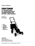
Thase accessorieswere availablewhen thislawn mowerwas produced. They are also
availableat most Sears retailoutletsand servicecenters. Most Sears storescan alsoorder
repairpartsfor you, whan you providethe model numberof your lawn mower. Sorne ofthese
accessoriesmay notapplyto your lawnmower.
LAWN
MOWER
PERFORMANCE
rt
CUPPING DEFLECTOR
FOR REAR DISCHARGE LAWN MOWERS
GRASS CATCHERS
FOR
REAR DISCHARGE
LAWN MOWERS
MULCHER KITS
s'r_iml
rp;q
FOR
SIDE DISCHARGE
GRASS
CATCHERS
LAWN MOWERS
"
GAS CANS
LAWN
MOWER
MAINTENANCE
MUFFLERS
AIR RLTER_
SPARK PLUGS
ENGINE OIL
Read these instTuctionsand this manual in its
entirety before you attempt to assemble or
operate your now lawn mower. Your new lawn
• Rolllawnmoweroutofcartonand check
cartonthoroughly
foradditional
loosepar_.
HOW TO SET UP YOUR LAWN
MOWER
mower has been assembled at the factory with
theexce_
of_se pads k_tunassemb_d
for shipping purposes. All pads such as nuts,
washers, bolts, etc., necessa_ to complete the
assembly have been placed in the parts bag.
To ensure safe and proper operation of your
lawn mower, all parts and hardware you
assemble must be tightened securely. Use the
correct tools as necessary to ensure proper
tightness.
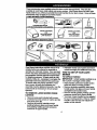
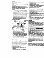
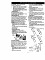
TO UNFOLD HANDLE
IMPORTANT: Unfold handles carefully so as
not to pinch or damage control cables.
• Raise handles u_l lower handle section
locks into place in mowing position.
• Remove protective padding, raise upper
handle section into place on lower handle
and tighten both handle knobs.
• Remove handle padding holding operator
presence control bar to upper handle.
• Your lawn mower handle can be adjusted
for your mowing comforL Refer to "Adjust
Handle" in the Sewice and Adjustment
section of this manual.
TO REMOVE LAWN MOWER FROM
CARTON
• Remove loose parts induded with mower.
• Cut down two end comors of carton and lay
end panel down flaL
• Remove all packing materiais except
padding between upper and lower handle
and padding holding operator presence
control bar to upper handle.
4
Operator
TO PREPARE
bar
BATTERY
NOTE: Your battery must be charged
before you can start your lawn mower.
Lift up
Mowing
position
Lower handle
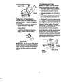
TO INSTALL ATTACHMENTS
Your lawn mower was shipped ready to be
used as a mulcher. To convert to bagging or
discharging:
• Open rear door and remove mulcher plug.
Store mulcher plug in a safe place.
• You can now install catcher or optional
clipping deflector.
• To return to mulching operation, install
mulcher plug into discharge opening of
mower. Be sure all tabs are seated
properly.
• Disconnect engine battery connector
(male) from battery connector (female)
• Connect battery charger connector
(male) to battery connector (female).
• Plug battery charger into 110 volt A.C.
outlet.
• Leave battery charger connected for 24
hours before starting your engine for
the first time.
• After charging, connect engine connector (male) to battery connector (female).
Your engine has an integral altemator for
partial charging. Connect your battery
charger to charge battery as required.
IMPORTANT:
The engine altemator will
not charge a discharged battery.
At the end of the mowing season the
battery should be charged for 48 hours to
protect the battery during winter storage.
ACAUTION:
Always disconnect the
engine connector (male) from the battery
connector (female) to prevent accidental
starting when transporting or storing your
lawn mower after the season.
Engine
connector
(Male)
Mulcher plug
ACAUTION"
Do not run your lawn mower
without mulcher plug in place or approved
clipping deflector or grass catcher in place.
Never attempt to operate the lawn mower
with the rear door removed or propped
open.
_E
Battery
charger
J
Battery
connector
(female)
5
y charger
connectror (male)
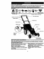
KNOW YOUR LAWN MOWER
READ THIS OWNER'S MANUALAND SAFETY RULES BEFORE OPERATING YOUR LAWN
MOWER. Compare the illustrationswithyour lawn mowerto familiarizeyourself withthe
locationof variouscontrolsand adjustments.Save this manualforfuture reference.
Thesesymbolsmayappearonyourla_nmowerorInlilmatum
supplied
withtheproduct.
Learnandundastand
thaememir_
CAUTION
ENGINE
OR WARNING
ON
ENGINE
OFF
FAST
SLOW
CHOKE
Key start switch
FUEL
OIL
DANGER, KEEP HANDS
AND FEET AWAY
presence control bar
Ddve control lever
Engine zone control cable,
Handle knob
Grass catcher
Mulcher plug
Gasoline cap
Primer
Housing
Engine oil
cap w/
dipstick
Wheel adjuster
(on each wheel)
MEETS CPSC SAFETY REQUIREMENTS
Sears rotary walk-behind power lawn mowers conform to the safety standards of the American
National Standards Institute and the U.S. Consumer Product Safety Commission. The blade
rums when the engine is running.
Operator presence control bar - must be
held dawn to the handle to start the engine.
Release to stop the engine.
Primer - pumps additional fuel from the
carburetor to the cytinder for use when starting
a cold engine.
Starter handle - used for starting the engine.
Ddve control lever - used to engage powerpropelled forward motion of lawn mower.
Mulcher plug - must be removed to convert to
bagging or discharging operation.
Key start switch - used for starting the
engine.
6
The operation of any lawn mowercan
result in foreign objects thrown into the
eyes, which can result in severe eye
damage. Always wear safety glasses or
eye shields while operating your lawn
mower or performing any adjustments or
repairs. We recommend a wide vision
safety mask over spectacles or standard
safety glasses.
HOW TO USE YOUR LAWN MOWER
ENGINE SPEED
•
The engine speed was set at the factory
for optimum performance. Speed is not
adjustable.
ENGINE ZONE CONTROL
TO ATFACH
Hinge
Rear door
ACAUTION:
Federal regulations require
an engine control to be installed on this
lawn mower in order to minimize the risk of
Grass catcher
frame
blade contact injury. Do not under any
circumstances attempt to defeat the
function of the operator control. The blade
turns when the engine is running.
• Your lawn mower is equipped with an
operator presence control bar which
requires the operator to be positioned
behind the lawn mower handle to stad and
operate the lawn mower.
TO ADJUST CUTnNG HEIGHT
• Raise wheels for low cut and lower wheels
for high cut.
• Adjust cutting height to suit your requirements. Medium position is best for most
lawns.
• To change cutting height, squeeze adjuster
lever toward wheel. Move wheel up or
down to suit your requirements. Be sure all
wheels are in the same setting.
NOTE: Adjuster is properly positioned
when plate tab inserts into hole in lever.
Also, 9-position adjusters (if so equipped)
allow lever to be positioned between the
plate tabs.
Formed
tabs
TO EMPTY GiRASS CATCHER
• To remove grass catcher, release operator
presence control bar to stop engine.
• Lift up rear door and remove the grass
catcher by the handle.
NOTE:
Do not drag the bag when
emptying; it will cause unnecessary wear.
Plate Tab
/
Lower Wheels for High Cut._
GRASS CATCHER
• Close the flip lid. Rip lid must be dosed
while operating lawn mower.
• Lift the rear door on the mower housing and
place the grass catcher frame onto the
formed tabs on the rear door hinge bracket.
• The grass catcher is secured to the lawn
mower housing when the rear door is
lowered onto the grass catcher frame.
ACAUTION:
Do not run your lawn mower
without clipping deflector or approved
grass catcher in place. Never attempt to
operate the lawn mower with the rear door
removed or propped open.
_ .,L_
Raise Wheels for Low Cut
7
DRIVECONTROL
• Self-propelling is controlled by holding
the operator presence control bar down
to the handle and pushing the drive
control lever forward until it dicks; then
release the lever.
• Forward motion will stop when the
operator presence control bar is
released. To stop forward motion
without stopping engine, release the
operator presence control bar slightly
until the drive control disengages. Hold
operator presence control bar down tO
handle to continue mowing without selfpropelling.
• To keep drive control engagedwhen
turning comers, push down on handle
and lift front wheels off ground while
tuming lawn mower.
Operator presence control bar
WARNING: Ex_
inSicates that alcohol
blended fuels (called gasohol or using ethanol
or methanol) cen attract moisture which leads
to separation and formation of acids during
storage.Addicgascandamagethefuel
system of an engine while in storage. To avoid
engine problems, the fuel system should be
emptied before storage of 30 days or longer.
Drain the gas tank, start the engine and let it
run until the fuel lines and carburetor are
empty. Use fresh fuel next season. See
Storage Instructions for additional information.
Never use engine or cafouretor cleaner
products in the fuel tank or permanent
damagemayoccur.
Engine il cap
/
Gasoline filler cap
Drive
control
TO START ENGINE
To engage drive
control
BEFORE STARTING
OIL
Drive conb'ol
disengaged
ENGINE
Your lawn mower is shipped without oil in the
engine.
• Be sure mower is level and area around oil
fill is clean.
• Remove engine ell cap and fill to the full line
on the dipslick
• Use 20 ozs. of oil. For type and grade of oil
to use, ,see =ENGINE" in Maintenance
section of this manual.
• Pour oil elowly. Do not over filL
• Check oil level before each use. Add ell if
needed. Fill to full line on dipstick.
• To read proper level, tighten engine oil cap
each time.
°
• Reinstall engine oil cap and tighten.
• Change the oil after every 25 houm of
eperation or each seasen. You may need
to change the oil more often under dusty,
dirty conS_iens.
GAS
• Fill fuel tank. Use fresh, clean, regular
unleaded gasoline with a minimum of 87
octane. Do not mix oil wtih gasoline.
Purchase fuel in quanElles that can be used
within 30 days to assure fuel freshness.
8
• To start a cold engine, push primer five
(5) times before trying to start. Use a
firm push. This step is not usually
necessary when starting an engine
which has already run for a few minutes.
• Hold operator presence control bar
down to the handle.
• Turn electric start key clockwise to crank
engine.
IMPORTANT:
Do not crank engine more
than five continous seconds between each
time you try to start. Wait 5 to 10 seconds
between each attempt.
• To start engine using the auxiliary
starter handle, follow the steps above.
Exchange the use of the start button for
starter handle. Pull starter handle
quickly. Do not allow starter rope to
snap back.
• To stop engine, release operator
presence control bar.
NOTE: In cooler weather it may be
necessary to repeat priming steps. In
warmer weather over priming may cause
flooding and engine will not start. If you do
flood engine wait a few minutes before
attempting to start and do not repeat
priming steps.
MOWING TIPS
MULCHING MOWING TIPS
• Under certain conditions, such as very
tall grass, it may be necessary to raise
the height of cut to reduce pushing effort
and to keep from overloading the engine
and leaving clumps of grass clippings. It
may also be necessary to reduce
ground speed and/or run the lawn
mower over the area a second time.
IMPORTANT: For best psrfonnance, keep
mower housing free of built-up grass and
trash. See "Cleaning" in Maintenance section
of this manual.
• For extremely heavy cutting, reduce the
width of cut by overlapping previously
cut path and mow slowly.
• For better grass bagging and most
cutting conditions, the engine speed
should be set in the fast position.
• When using a roar discharge lawn
mower in moist, heavy grass, clumps of
cut grass may not enter the grass
catcher. Reduce ground speed (pushing speed) and/or run the lawn mower
over the area a second time.
• The special mulching blade will recut the
grass clippings many times and reduce
them in ,_ze so that as they f_ onto the
lawn they will disperse into the grass and
not be noticed. Also, the mulched grass will
biodegrade quickly to provide nutrients for
the lawn. Always mulch with your highest
engine (blade) speed as this will provide the
best recutting action of the blades.
• Avoid cutting your lawn when it is wet. Wet
grass tends to form dumps and interferes
with the mulching action. The best time to
mow your lawn is the early afternoon. At
this time the grass has dried and the newly
cut area WIUnot be exposed to the direct
sun.
• If a trail of clippings is left on the right
side of a rear discharge mower, mow in
a clockwise direction with a small
overlap to collect the clippings on the
next pass.
• Pores in cloth grass catchers can
become filled with dirt and dust with use
• For best results, adjust the lawn mower
cutting height so that the lawn mower cuts
off only the top one-third of the grass blade_
If the lawn is overgrown it will be necessary
to miss the height of cut to reduce pushing
effort and to keep from overloading the
engine and leaving clumps of mulched
grass. For extremely heavy mulching,
reduce your width of cut by overlapping
previously cut path and mow slowly.
• Certain types of grass and grass conditiom
may require that an area be mulched a
second time to completely hide the
and catchers will collect less grass. To
prevent this, regularly hose catcher off
with water and let dry before using.
• Keep top of engine around starter clear
and clean of grass clippings and chaff.
This will help engine air flow and extend
engine life.
cr=ppings.
Wben doinga secondcut,mow
across or perpendicular to the first cut path.
• Change your cutting pattern from week to
week. Mow nodh to ssuth one week then
change to east to west the next week. Thi_
will help prevent matting and graining of th_
lawn.
, "
9
_ ' _.
Max 1/3
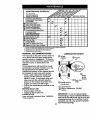
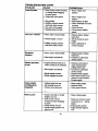
nEGO ,O
/SER IOE
Check for Loose Fasteners
Clean/Inspect Grass Catcher
(If Equipped)
Clean Lawn Mower
Clean Under Drive Cover
(Power-Propelled Mowers)
Check drive bed/pulleys
(Power-Propelled Mowers)
_
W
R
v'
I I/'
"
I/
t__
hi'
Check/Sharpen/Replace Blade
Ifs
LubricationChart
Clean Battery/Recharge
IElectric Start MowersI
t/
E
Check
Oil Level
ChangeEngine
EngineOil
GI
Clean
Air
Filter
Inspect
Muffler
_
-
I/'4
l# °
_2
BE Replace
Clean orAir
Replace
Spark Cartridge
Plug
Filter Paper
1
2
3
4
DATES
2
Change morn o_m when operating under a heavy load ot in high arr_ient temperatures.
Sen_ce more often when operating in ditty of dusty c_tions.
Replace blades more often when mou,tng in sandy soil.
Charge 48 hours at end of season.
GENERAL RECOMMENDATIONS
LUBRICATION
The warranty on this lawn mower does not
cover items that have been subjected to
operator abuse or negligence. To receive
full value from the warranty, operator must
maintain mower as instructed in this
manual.
Some adjustments will need to be made
periodically to properly maintain your unit.
All adjustments in the Service and
Adjustments section of this manual should
be checked at least once each season.
(_) Wheel
adjuster
• Once a year, replace the spark plug,
replace air filter element and check
blade for wear. A new spark plug and
clean/new air filter element assures
(_
CHART
Engine
oil
Brake
spring
bracket
i_
proper air-fuel mixture and helps your
engine run better and la_stlonger.
• Follow the maintenance schedule in this
manual.
BEFORE EACH USE
(_) Handle bracket
mounting pin
Rear door
hinge
(_) Spray lubricant
(_ Referto Maintenance "ENGINE"
section.
• Check engine oil level
• Check for loose fasteners.
LUBRICATION
IMPORTANT: Do not oil or grease plastic
wheel beatings. Viscous lubricants will attract
dust and dirtthat will shorten the life of the self
Keep unit well lubricated (See "LUBRICATION CHART").
10
lubricating bearings. If you feel they must be
lubricated, use only a dry, powdered graphite
type lubricant sparingly.
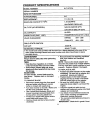
PRODUCT
MODEL
SPECIFICATIONS
NUMBER
SERIAL
917.377574
NUMBER
DATE OF PURCHASE
HORSEPOWER:
6.5
DISPLACEMENT:
11.5 CU. IN.
GASOLINE
1.25 QUARTS
CAPACITY/TYPE:
UNLEADED
OIL TYPE
(API-SF/SG/SH):
REGULAR
SAE 30 (ABOVE
32°F)
SAE 5W-30 (BELOW
OIL CAPACITY:
SPARK PLUG (GAP:
32°F)
20 OZS.
.030")
CHAMPION
VALVE CLEARANCE:
RJ19LM OR J19LM
INTAKE:
.004 - .008
EXHAUST:
.004 - .008
SOLID STATE IGNITION
;AIR GAP:
I
....
BLADE
.0:125 IN.
•
BOLT TORQUE:
35-40 FT. LBS.
The model and serial numbers will be found on a decal attached to the roar of the
lawn mower housing.Record
provided above.
LAWN
both sedal number and date of purchase in space
MOWER
Always observe safety rules when performing
any maintenance.
TIRES
• Keep tires free of gasoline, oil, or insect
control chemicals which can harm robber.
• Avoid stumps, stones, deep ruts, sharp
objects and other hazards that may cause
tim damage.
BLADE CARE
For best results, mower blade must be
kept sharp.
Replace bent or damaged
blades.
TO REMOVE
BLADE
• Disconnect spark plug wire from spark
plug and place wire _vhere it cannot
come in contact with spark plug.
• Turn lawn mower on its side. Make sure
air filter and carburetor are up.
• Use a wood block between blade and
mower housing to prevent blade from
turning when removing blade bolt.
• Protect your hands with gloves and/or
wrap blade with heavy cloth.
• Remove blade bolt by turning counterclockwise.
• Remove blade and attaching hardware
(bolt, lock washer and hardened
washer).
NOTE: Remove the blade adapter and
check the key inside hub of blade adapte=
The key must be in good condition to wor
properly. Replace adapter if damaged.
TO REPLACE
BLADE
• Position the blade adapter on the engi_
crankshaft. Be sure key in adapter anc
crankshaft keyway are aligned.
• Position blade on the blade adapter
aligning the two (2) holes in the blade
with the raised lugs on the adapter.
• Be sure the trailing edge of blade
(opposite sharp edge) is up toward the
engine.
• Install the blade bolt with the lock
washer and hardened washer into blad
adapter and crankshaft.
• Use block of wood between
blade and
lawn mower housing and tighten the
blade bolt, turning clockwise.
• The recommended tightening torque is
35-40 ft. Ibs.
IMPORTANT:
11
Blade bolt is grade 8 heal
treated.
TO SHARPEN
BLADE
NOTE: We do not recommend sharpening
blade - but if you do, be sure the blade is
balanced.
Care should be taken to keep the blade
balanced. An unbalanced blade will cause
eventual damage to lawn mower or
engine.
• The blade can be sharpened with a file
or on a grinding wheel. Do not attempt
to sharpen while on the mower.
• To check blade balance, drive a nail ihto
a beam or wall. Leave about one inch of
the straight nail exposed. Place center
hole of blade over the head of the nail.
If blade is balanced, it should remain in
a horizontal position. If either end of the
blade moves downward, sharpen the
heavy end until the blade is balanced.
GRASS CATCHER
E_ade
Crank shaft
keyway
• To keep your drive system working
properly, the gear case and area aroun
the drive should be kept clean and free
of trash build-up. Clean under the ddv_
cover twice a season.
• The gear case is filled with lubricant to
the proper level at the factory. The onl'
time the lubricant needs attention is if
service has been performed on the ge_
case.
• If lubricant is required, use only Texac(
Starplex Premium 1 Grease, Part No.
750369. Do not substitute.
ENGINE
LUBRICATION
Use only Iligh quality detergent oil rated
with API service classification SF, SG or
SH. Select the oil's SAE viscosity grade
according to your expected operating
temperature.
Blade
bolt
• Remove any trash or grass cuttings fr¢
inside the dust cover, pinion and/or dfi
wheel gear teeth.
• Put wheels back in place.
• tt after cleaning, the drive wheels do n
turn freely, contact your nearest
authorized service center.
GEAR CASE
Crank
shaft
Lock
washer
Blade
Hardened edge
adapter
washer
• The grass catcher may be hosed with
water, but must be dry when used.
• Check your grass catcher o_ten for damage
or deterioration. Through normal use it will
wear. If catcher needs replacing, replace
only with a manu|acturor approved
replacement catcher. Give the lawn mower
model number when ordering.
DRIVE WHEELS
Check front drive wheel*s each time before
you mow to be sure they move freely.
The wheels not turning freely means trash,
grass cuttings, etc. are in the drive wheel
area and must be cleaned to free drive
wheels.
NOTE: Although multi-viscosity oils
(5W30, 10W30 etc.) improve starting in
cold weather, these multi-viscosity oils wil
result in increased oil consumption when
used above 32°F. Check your engine oil
level more frequently to avoid possible
engine damage from running low on oil.
Change the oil after every 25 hours of
operation or at least once a year if the
lawn mower is not used for 25 hours in
one year.
Check the crankcase
oil level before
starting the engine and after each five (5)
hours of continuous use. Tighten oil plug
securely each time you check the oil level
If necessary to clean the drive wheels,
check both front wheels.
• Remove hubcaps, hairpin cotters and
washers.
• Remove wheels from wheel adjusters.
12
TOCHANGE
ENGINE OIL
NOTE: Before tipping lawn mower to drain
oil, drain fuel tank by running engine until
fuel tank is empty.
MUFFLER
• Disconnect spark plug wire from spark plug
and place wire where it cannot come in
contact with spark plug.
• Remove engine oil cap; lay aside on a clean
surface.
• Tip lawn mower on its s'Klea_ _
and
drain oil into a suitable container. Rock lawn
mower back and forth to remove any oil
trapped inside of engine.
• Wipe off any spilled oil on lawn mower and
on side of engine.
• Fill engine with oil. FiUonly to the "FULL"
line on the dipstick. DO NOT overfill.
• Replace engine oil cap.
• Reconnect spark plug wire to spark plug.
Change your spark plug each year to make
your engine start easier and run better. Set
spark plug gap at .03O inch.
CLEANING
Container
AIR RLTER
Your engine will not run propedy and may
be damaged by using a dirty air filter.
Replace the air filter every year, more
often if you mow in very dusty, dirty
conditions. Do not wash air filter.
TO CHANGE AIR FILTER
• Remove the air filter by turning clockwise to the stop and pull away from
collar,
• Remove filter from inside of cover.
• Clean the inside of the cover and the
collar to remove any dirt accumulation.
• Insert new filter into cover.
• Put air filter cover and filter into collar
aligning the tab with the slot.
• Push in on cover and turn counterclockwise to tighten.
Inspect and replace corroded muffler as it
could create a fire hazard and/or damage.
SPARK PLUG
IMPORTANT:
For best performance, keep
mower housing free of built-up grass and
trash. Clean the underside of your mower
after each use.
,&CAUTION:
Disconnect spark plug wire
from spark plug and place wire where it
cannot come in contact with the spark
plug.
•Tum
lawn mower on its side. Make sure air
filter and carburetor are up. Clean the
underside of your lawn mower by scraping
to remove build-up of grass and trash.
• Clean engine often to keep trash from
accumulating. A clogged engine runs hotter
and shortens engine life.
• Keep finished surfaces and wheels free of
all gasoline, oil,etc.
• We do not recommend using a garden
hose to clGan lawn mower unless the
electrical system, muffler, air filter and
carburetor are covered to keep water out.
Water in engine can result in shortened
engine life.
CLEAN UNDER DRIVE COVER
Clean under drive cover at least twice a
season. Serape underside of cover with putty
knife or similar tool to remove any build-up of
trash or grass on underside of drive cover.
Collar
Tum
Remove
Slot
Tum
Air Filter
Tab
Air Filter
Cover
CounterClockwise to
13
Tighten
ACAUTION:
Before performing any
service and adjustments:
•
Release control bar and stop engine.
•
Make sure the blade and all moving
parts have completely stopped.
•
Disconnect spark plug wire from spark
plug and place where it cannot come
in contact with plug.
"
LAWN MOWER
TO ADJUST CuI"nNG
• Remove the controls and operator
presence control bar from the upper
handle.
• Remove hairpin cotters.
• Disconnect the lower handle from the
handle brackets.
• Turn the handle over and reassemble
the hairpin cotters that have been
removed.
• Route cable(s) below crossbar of lower
handle and reassemble the controls and
the operator presence control bar to the
upper handle.
&CAUTION: The operator presence
control bar must pivot freely to permit
blade brake engagement when control bar
is released. Do not over tighten the
fasteners holding the controls to the upper
handle.
HEIGHT
See 'q'O ADJUST CUTI'ING HEIGHT" in the
Operation section of this manual.
REAR DEFLECTOR
The rear deflector, attached between the rear
wheels of your lawn mower, is provided to
minimize the possibilitythat objects will be
thrown out the roar of the lawn mower into the
operator's mowing position, ff the rear
detlector becomes damaged, it should be
• To change from medium low to high
position only the upper handle section will
have to be turned over.
replaced.
TO REMOVE/REPLACE
DRIVE BELT
• Remove drive cover. Remove belt by
pushing down on gear case pulley and roll
belt off.
• Turn lawn mower on its side with carburetor
• To change from medium low to low pesition,
only the lower hanale section will have to be
turned over.
Shipping position
Medium low
and fuel cap up.
• Remove blade.
• Remove debrisshield.
Medium high
• Remove belt from engine pulley on
crankshaft.
• Install new belt by roversing above steps.
• Always use factory approved belt to assure
and
f e.
Drive l_hk
cover
V
Low
High
Belt _.__7--[_=_
Push
down
f
TO ADJUST HANDLE
Your lawn mower handle can be raised or
lowered for your mowing comfort.
Four
(4) positions are available: high, medium
high, medium low and low. Handles are
shipped mounted in the medium low
position.
• To change from medium low to medium
high position, the upper and lower
handle sections will have to be turned
over.
• Remove the cable clips.
_,
Squeeze to
Lower handle
_'__
bracket
14
ENGINE
SPEED
Sewn
hem
Tubular frame
Your engine speed has been factory set.
Do not attempt to increase engine speed
or it may result in personal injury. If you
believe that the engine is running too fast
or too slow, take your lawn mower to an
authorized service center for repair and
adjustment.
CARBURETOR
Your carburetor has a non-adjustable fixed
main jet for mixture control. If your engine
does not operate properly due to suspected carburetor problems, take your
lawn mower to an authorized service
Sewn hem
Lower frame
center for repair and/or adjustment.
IMPORTANT:
Never tamper with the
engine governor, which is factory set for
the proper engine speed. Overspeeding
the engine above the factory high speed
scan be dangerous, if you think the
engine-governed high speed needs
adjusting, contact your nearest authorized
service center, which has proper equipment and experience to make any
necessary adjustments.
TO ASSEMBLE
GRASS CATCHER
o
must be
fully
seated)
_
(Frame_
Tubular frame
• Insert leg of tubular frame through front
opening of grass catcher and thread
frame into sewn hem of bag.
NOTE: Keep bag hem gathered on the
straight leg of the tubular frame.
• When frame comes out the other end of
Lower frame handle
sewn hem, immediately work the end of
frame down inside the bag as shown in
inset.
• Slide sewn hem evenly around the
tubular frame until both ends of frame
are exposed out of the front opening.
• Assemble lower frame to tubular frame
as shown. Be sure handle is outside of
bag and frames
shown in inset.
Flip lid
are fully seated as
• Slip vinyl bindings over frame.
NOTE: If vinyl binding_ are too stiff, hold
them in warm water for a few minutes. If
bag gets wet, let it dry before using.
• CLose the flip lid. Flip lid must be closed
while operating lawn mower.
&CAUTION:
Do not run your lawn mower
without clipping deflector or approved
grass catcher in place. Never attempt to
operate the lawn mower with the rear door
removed or propped open.
15
Immediately prepare your lawn mower for
storage at the end of the season or if the unit
will not be used for30 days or more.
LAWN
Operator presence control bar
Fold foward
for storage
MOWER
When _wn mower is to be stored for a period
of time, clean it thoroughly, remove all dirt,
grease, leaves, etc. Store in a ='lean, d_J area.
• Clean entire lawn mower (See "CLEANING"
in the Maintenance section of this manual).
• Lubricate as shown in the Maintenance '
section of this manual.
• Be sure that all nuts, bolts, screws, and pins
are securely fastened. Inspect moving
parts for damage, breakage and wear.
Replace if necessary.
• Touch up all rusted or chipped paint
surfaces; sand lightlybefore painting.
HANDLE
You can fold your lawn mower handle for
storage.
• Squeeze the bottom ends of the lower
handle toward each other until the lower
handle clears the handle bracket, then
move handle totwerd.
• Loosen upper handle mounting bolts
enough to allow upper handie to be folded
beck.
IMPORTANT: When folding the handle for
storage or transportation, be sure to fold the
handle as shown or you any damage the
control cables.
• When setting up your handle from the
storage position, the lower handle will
automatically lock into the mowing position.
Lower
handle
Squeeze to fold
Upper
Fold
backward
Lower
handle
Mowing
position
ENGINE
FUEL SYSTEM
IMPORTANT: It is important to prevent gum
deposits from forming in essontJalfuel system
parts such as carburetor, f fuel filter, fuel hose
or tank during storaga. Also, experience
indicates that alcohol blended fuels ( called
gasoholor usingethanol or m_anol) can
attract moisture which leads to separation an(
formation of acids during storage. Acidic gas
can damage the fuel system of an engine
while in storage.
• Drain the fuel tank.
• Start the engine and let if run until the fuel
lines and carburetor are empty.
• Never use engine or carburetor cleaner
products in the fuel tank or permanent
damage may occur.
• Use fresh fuel next season.
NOTE: Fuel stabilizer is en aoceptable
alternative in minimizing the formation of fuel
gum deposits during storage. Add stabilizer t(
gasoline in fuel tank or storage container.
Always follow the mix ratio found on stabilizer
container. Run engine at least 10 minutes
after addng stabilizer to allow the stabilizer to
reach the caTburetor. Do not drain the gas
tank and carburetor if using fuel stabilizer.
bracket
Hairpin
(_otter
16
ENGINEOIL
Drainoil(withenginewarm)andreplacewith
cleanengineoil. (See"ENGINE" in the
Maintenance section of this manual).
CYLINDER
• Remove spark plug.
• Pour one ounca (29 ml) of oil threugh spark
plug hole into cylinder.
• Pull starter handle slo_y a few times to
distribute oil.
• Replace with new spark plug.
BATrERY
Disconnect the battery from the engine'
connector and charge battery 48 hours.
OTHER
• Do net store ga_ine
another.
from one season to
TROUBLESHOOTING
PROBLEM
Does not start
• .eplace yourgasolinecan ifyourcan start
to rust. Rustand/or dirtin your gasolinewi
cause problems.
• Ifpossible,store your unitindoorsand cove
itto give protectionfromdustand dirt.
• Cover your unitwith a suitableprotective
coverthat does nol retainmoisture.Do no
use plastic. Plastic cannotbreathe which
allows condensationto form and willcause
your unitto rust.
IMPORTANT: Never cever mowerwhile
engine and e_aust areas are stillwarm.
&CAUTION: Never store the lawn mowe
with gasoline in the tank inside a building
where fumes may reach an open flame or
spark. Allow the engine to cool before
storing in any enclosure.
CHART
CAUSE
CORRECTION
• Dirty air tilter.
• Out of fuel.
• Stale fuel,
Cloan/replace air tilter.
Fill fuel tank.
Drain tank and refill with
• Water in fuel.
fresh clean fuel,
Drain fuel tank and
carburetor and refill tank
with fresh gasoline.
• Spark plug wire is
disconnected.
Connect wire to plug.
• Bad sparkplug.
• Looseblade orbrokenblade
adapter.
• Controlbar in released
position.
• Controlbar defective.
17
• Replacespaxkplug.
• TK:jhtenbladeboltor
replacebladeadapter.
° Depress controlbar to
handle.
* Replacecontrol bar,
TROUBLESHOOTING
CHART
PROBLEM
CAUSE
CORRECTION
Loss of l_-wer
• Rear oflawn mower housing
or cuttingblade dragging
in heavygrass
• Cuttingtoo much grass
• Set to =HigherCut"
position
• Dirty air filter,
• Clean/replace air filter
• Clean underside of mower
• Buildup of grass, leaves,
end trash under mower
• Too much oil in engine
• Walking speed too fast
• Set to "Higher Cut"
position
housing
• Check oil level
• Cut at slower walking
speed
Poor cut - uneven
• Worn, bent'orlooseblade.
• Replace blade T_nten
blade boll
• Wheel heights uneven
• Set ail wheeis at same
• Buildupof grass,leaves
and trashunder mower.
Excessive
• Worn, bent or loose blade.
vibration
• Bent engine crankshaft.
Starter rope haed
to pull
• Engineflywheel brake ison
when controlbar is released
• Bent engine crankshaft
height
• Clean underside of
mower housing
• Replace blade I-_jhten
blade bolt
• Contact an authorized
service center.
• Depress control bar to
upper handle before
pulling starter rope.
• Contact an authorized
service center.
• Blade adapter broken
• Blade dragging in grass
• Replace blade adapter
• Move lawn mower to cut
grass or to hard surtace
to start engine
,Grasscatcher
notfilling('d'so
equipped)
Hard to push
• Cutting height too low.
• Lift oll blade worn off.
• Raise cutting height
• Catcher not venting air
• Replace blade
• Clean grass catcher
• Grass is too high or wheel
• Raise cutting height.
height is too low
• Rear of lawn mower
• Raise rear of lawn mower
housing or blade dragging
in grass
• Grass catcher too full.
• Handle height position not
right for you.
18
housing one (1) setting
higher
• Empty grass catcher
• Adjust handle height to
suit.
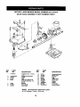
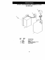
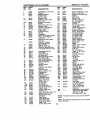
ROTARY
GEAR
LAWN
MOWER
MODEL
CASE ASSEMBLY
NUMBER
PART NUMBER
917.377574
702511
i
14
KEY
NO.
PART
NO.
17490416
2
3
4
6
137055X004
137053
57072
48373
7
8
9
77881
137051
137074
KEY
NO.
DESCRIPTION
Tapping Screw 1/4-20 x
1-1/'4
Engagement Bracket
Shifte_
Seal
Gear Case Halves Kit
(includes Key Nos. 4, 5,
and 7)
Bearing
Worm Shaft
Drive Shaft
10
11
12
13
14
15
16
17
18
19
PART
NO.
57079
131484
700343
86447
137050
750436X
750369
13000003
850848
81585X004
NOTE: All component dimensions given
in U;S. inches. 1 inch = 25.4 mm
36
DESCRIPTION
Hardened Washer
Clutch Yoke
Bushing
Plug
HelicalGear
Clutch Jaw
Grease
E-Ring
Hi-Pro Key
Spdng Bracket
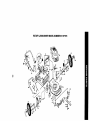
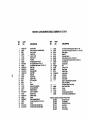
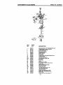
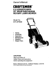
ROTARY LAWN MOWER MODEL NUMBER 917.377574
BATTERY ART
4
3
\
2
KEY
NO.
1
2
3i
4
5
PART
NO.
157553
750909
17411312
86353
111549X
DESCRIPTION
Battery Bracket
Battery
HexWasher Head Screw 13x.750
Connector Mounting Clip
Battery Charger
37
ROTARY LAWN MOWER MODEL NUMBER 917.377574
7s.
2e
io 29
73
32
(.o
co
lO
29
28
75
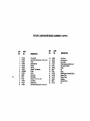
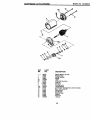
ROTARY LAWN MOWER MODEL NUMBER 917.377574
KEY
NO,
Co
_D
1
2
3
6
7
9
10
11
12
13
14
15
16
17
20
21
22
23
25
26
27
28
29
3O
31
32
34
35
37
38
39
4O
PART
N_
165451X479
158655
63601
136376
751152
151023
128415
150050
STD512505
144929
156374X479
700365X479
13313OX479
14O661X479
140540
150425
85543
87677
83923
57143
151138
142748
61651
750913X004
701037
700331X004
146630
700325X007
15O078
88348
161814X479
161512X479
DESCRIPTION
Upper Handle
Zone ControlAsm.(IncludingCable)
NylonLockNut
HandleKnob
Locknut1/4-20
Rear DoorKit
Pop Rivet
SeflTapplng Screw#10-24
Hex TappingScrew 1/4-20 x 1/2
Hex Washer Head Screw 1/4-20 x 2-1/8
Back Plate
Side Baffle
DischargeBaffle
Rear Baffle
Rear Skirt
MulcherPlug
EnginePulley
Hi-Pro Key#505
Nut
Washer
Wheal & "i'lmAseambly
ShoulderBolt3/6-16
BallavilleWasher
AxleArm Aseambly
SelectorKnob
SelectorSpdng
Spacer
Wheel AdjustingBracket
"l_madCuttingScrew 5/16-18 x 3/4
Washer
HandleBracketAssembly(Left)
Handle BracketAssembly(Right)
KEY
NO.
PART
NO.
41
44
46
47
48
49
50
51
52
53
55
56
57
58
59
61
62
64
150406
160677
851514
157101
851074
850263
851084
165548
85463
74760612
751592
88652
51793
157081X479
131959
132001
134612
......
72
73
74
75
76
--
......
169806
66426 *
151440
161058
166063
DESCRIPTION
Hex Head Thread RollingScrew 3/8-16 x 1-1./8
LawnMowerHousing(Incl.Key #14,15, 17, 51 & 52)
BladeAdapter
Blade22"
HardenedWasher
HelicalWasher 3/8-24 x 1-3/5Grd. 8
Hex Head MachineScrew 3/8-24 )_1-3/8 Grd.8
FrontBaffle Kit
DangerDecal
Bolt
Locknut3/8-16
HingeScrew
Hairpin Cotter
Lower Handle
HandleBolt
Rope Guide
DebdsShield
Engine- (Sea Breakdown)Craftsman
Model 143.996504
Sea Battery RepairParts Page
Zone ControlCable
Wiretie
Hub Cap
Wamlng Decal(NotShown)
Owners Manual(EngllshiSpanlsh)
Availableacceasodasnotincludedwithlawn mowen
71 33623
Gas Can (2.5 gal.)
71 _
FuelStabilizer
71 3.3000
SAE 30W Oil (2Ooz.)
71 33417
DustShield
71 33316
Mower Cover
71 33303
Chute Deflector
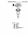
ROTARY LAWN MOWER MODEL NUMBER 917.377574
13
Q
18
14
ROTARY LAWN MOWER MODEL NUMBER 917.377574
=_.
KEY
NO.
PART
NO.
2
4
5
6
8
9
11
12
13
14
15
16
17
18
27
145755
158755
146527
150495
150182
145212
150340
12000058
137054
88080
88118
67725
145793
701037
143603
DESCRIPTION
Drive Control
Hex Washer Head Scrow 1/4-20 x 2-1/8
V-Belt
Spdng Retainer
Hubcap
Hex Nut
Wheel & Tire Assembly
E-Ring
Pinion
Dust Cover
Felt Washer
Washer 1/2 x 1-1/2 x .134
Control Bar
Selector Knob
Hex Washer Head Screw #10-24 x 3/4
KEY
NO.
28
31
32
35
36
37
38
40
41
52
53
54
55
56
PART
NO.
154990
132010
157052
151521
702511
137090
63601
75192
151520
144748
144747
166070
86012
751152
DESCRIPTION
Drive Cover
Hax Flange Nut
Drive Pulley
Wheel Adjuster Assembly (Left)
Gear Case Asserhbly
Spring
Nut
Spring
Wheel Adjuster Assembly (Right)
Catcher Tube
Catcher Throat
Grassbag
Driveshaft Cover
Nut
CRAFTSMAN
4.-CYCLE ENGII_E
MODEL NO. 143.996504
130
120
125
16
1821_
239
178
245
238
250
42
CRAFTSMAN
KEY
NO.
PART
NO.
1
2
6
7
37266
26727
33734
36557
12
12A
36775
36558
12B
14
15
16
17
18
36694
28277
30589
34839A
31335
651018
19
20
30
40
36281
32600
35801
40027
40028
41
40025
40026
42
43
45
46)
46
46
5O
52
69
7O
40006
4O0O7
20381
36777
32610A
27241
36778
29914
35261
34311E
72
73
75
80
81
82
30572
28833
27897
00574A
30590A
30591
83
86
89
90
92
93
100
101
103
50588A
650488
611004
611150
650815
650816
34443B
610118
651007
110
110A
110B
119
120
125
37047
36953
36954
36787
36825
37288
126
130
135
37289
6021A
35395
150
151
151A
169
172
174
31672
31673
40017
36783
36784
30200
4-CYCLE
MODEL NO. 143.996504
ENGINE
DESCRIPTION
Cylinder (Incl. 2,20 & 150)
Dowel Pin
Breather Element
Breather Ass'y.
(Incl. 6 & 12A)
Breather Tube
Breather Cover & Tube
(Incl. 12B) •
Breather Tube Elbow
Washer
Governor Rod (Incl. 14)
Governor Lever
Governor Lever Clamp
Screw, Ton( T-15,
8-32 x 19/64"
Extension Spring
Oil Seal
Crankshaft
Piston, Pin & Ring Set (Std.)
Piston, Pin & Ring Set
(.010" OS)
Piston & Pin Ass'y. (Std.)
(Incl. 43)
Piston & Pin Assay.
(.010" OS) (Incl.43)
Ring Set (Std.)
Ring Set (.010" OS)
Piston Pin Retaining Ring
Connecting Rod Ass'y. (Incl.
KEY
NO.
PART
NO.
178
182
184
29752
6201
26756
185
186
189
191
36785
32653
650831
36559A
195
196
207
216
223
224
238
239
241
245
250
260
261
262
263A
275
277
295
287
290
292
298
300
610973
35035
34336
33086
650451
36796
650932
34338
36919
36905
36920
36980
30200
650831
36921
36790
650988
35000A
650926
29774
26460
28763
36916
DESCRIPTION
Nut & LOckWasher, 1/4-26
Screw, 1/4-28 x 7/8"
* Carburetor To Intake Pipe
Gasket
Intake Pipe
Governor Link
Screw, 1/4-20 x 1/2"
S.I_. Brake Bracket
(Include. 195)
Terminal
Power Restart Switch
Throttle Link
R.P.M. AdjustingLever
Screw, 1/4-20 x 1"
* Intake Pipe Gasket
Screw, 10-32 x 49/64
* Air Cleaner Gasket
Air Cleaner Collar
Air Cleaner Filter
Air Cleaner Cover
Blower Housing
Screw, 10-24 x 9/16"
Screw, 1/4-20 x 1/2"
Starter Grill
Muffler
Screw, 1/4-20 x 2-5/16"
Starter Cup
Screw, 8-32 x 21/64"
Fuel Line
Fuel Line Clamp
Screw, 10-32 x 35/64"
Fuel Tank
(Include. 292 & 301)
Fuel Cap
Oil FillTube
* "O'-Ring
"O'-Ring
Screw, 10-32 x 1/2"
Dipstick
Spacer
Screw, 8-32 x27/64"
Altamator Coil
COnnectorBody
Connector Body
Spring Clip
Spdng Clip
Screw, 10-32 x 51164"
LubricationDecal
Primer Decal
Carburetor (Incl. 184)
Rewind Starter
Electric Starter Motor
(12 Volt)
Gasket Set
(Incl. Items Marked *)
Spark Arrestor Kit
(Incl. 417)(Optional)
Screw, 10-32 x 1/2"
(Optional)
Replacement Engine NONE
Replacement S/B 750832,
order from 71-999
RPM High 2900 to 3200
Connecting Rod Bolt
Valve Lifter
Camshaft (MCR)
301
36246
Oil Pump Ass'y.
305
35647
* Mounting Flange Gasket
306
36996
Mounting Flange
307
35499
(Incl. 72 thru 83,306)
309
650562
Oil Drain Plug (Incl. 73)
310
35648
Drain Plug Gasket
Oil Seal
313
34080
314
650767
Governor Shaft
Washer
315
36952
322
35013
Governor Gear Assay.
322A
610885
(Incl. 81)
325
35249
Governor Spool
325A
37152
Screw, 1/4-20 x 1-1/4"
347
651038
Flywheel Key
370A
36261
Flywheel
Be!leville Washer
370C
37199
380
640174
Flywheel Nut
390
590739
Solid State Ignition
395
35709
Spark Plug Cover
Screw, Ton( T-15,
10-24 x 15/16"
400
36792B
Grour_:lWire
416
36085
Ground Wire
D.C. Starter Wire
417
650821
* Cylinder Head Gasket
Cylinder Head
900
Exhaust Valve (Std.)
9O0
(Include. 151)
Intake Valve (Std.) (Incl. 151)
Screw, 5/16-18 x 1-1/2"
Resistor Spark Plug
NOTE: This engine could have been builtwith 590702
(RJ19LM)
starter
Valve Spdng
Valve Spring Cap
Intake Valve Seal
NOTE: Allcomponent dimensions given in U.S. inches
* Valve Cover Gasket
1 inch = 25.4 mm
Valve Cover
Screw, 10-24 x 9/16"
43
CRAFTSMAN
4-CYCLE
KEY
NO.
ENGINE
PART
NO.
640174
1
631615
2
631767
4
631184
5
631183
6
640070
7
650506
16
631807
17
651025
18
630766
20
640018
20A
640053
25
J 631867
27
631024
28
632019
29
631028
30
631021
31
631022
35
36045A
36
64O08O
36A
632766
37
632547
40
640175
44
27110A
47
630748
48
631027
48A
631027
6O
632760
MODEL NO. 143.996504
DESCRIPTION
Carburetor (Ind. 184 of Engine Parts List)
Throttle Shaft & Lever Assembly
Throttle Return Spring
* Dust Seal Washer
• Dust Seal (Throttle)
Thmttte Shutter
• Shutter Screw
Fuel Fitting
Throtlle Crack Scraw/ldle Speed Screw
Tension Spring
Idle Restrictor Screw
Idle Restrictor Screw Cap
Float Bowl
* Float Shaft
Float
* Float Bowl "O" Ring
• Inlet Needle, Seat, & Clip (Incl. 31)
Spdng Clip
Primer Bulb/Retainer Ring
Main Nozzle Tube
CadouretorTube
* "O" Ring, Main Nozzle Tube
High Speed Bowl Nut
Bowl Nut Washer
• Welch Plug, Idle Mixture Well
• Welch Plug, Atmospheric Vent
* Welch Plug
Repair kit (Incl. Items Marked *)
44
CRAFTSMAN
4-CYCLE
ENGINE
MODEL NO. 143.996504
11C
12
12
KEY
NO.
1
2
3
4A
5B
6
7
8
10A
11C
12
13
14
15
16
17
18
PART
NO.
35709
34955
34950
34954
34949A
34953
33450
o34944
34945
590500
35714
34947
34946
34951
34952
34948
34953
590608
DESCRIPTION
Electric Starter (12 Volt)
Retainer Ring
Spring Retainer
Spdng
Gear
Drive End Cap Ass'y.
Lock Nut
Armature
Housing Ass'y.
Thrust Washer
Commutator End Cap Ass'y. (Incl. brushes)
Bolt. 10-32 x 3-3/16"
Pinion Driver
Cup Washer
Retainer Ring
Washer
Drive Nut
Washer
45
CRAFTSMAN
4-CYCLE
ENGINE
MODEL NO. 143.99650_
--
fl
13
O
,,
'_3
5
O_2
KEY
NO.
1
2
3
t4
5
6
7
8
11
12
13
PART
NO.
DESCRIPTION
590702
590599A
590600
590696
590601
590697
590698
590699
590700
590703
590535
590701
Recoil Starter
Spdng Pin (Incl. 4)
Washer
Retainer
Washer
Brake Spdng
Starter Dog
Dog Spring
Pulley & Rewind Spring Ass'y.
Starter Housing Ass'y, (40 degree grommet)
Starter Rope ( 98" X 9/64" dia.)
Starter Handle
46
CRAFTSMAN
4-CYCLE
ENGINE
MODEL NO. 143.996504
V--14
!
13
Ill /I -7
KEY
NO.
PART
NO.
3
6
7
8
11
590739
590740
590616
590617
590618A
o 590638
12
590535
13
14
590701
590760
DESCRIPTION
Rewind Starter
Retainer
Starter Dog
Dog Spring
Pulley & Rewind SpringAss'y
Starter Housirtg Ass'y (40 degree
grommet)
Starter Rope (Length 98" x 9/64"
dia.)
Starter Handle
Spring Clip
47
FortheTepair
or replacement parts you need
delivered directly to your home
Call 7 am - 7 pm, 7 days a week
1-800-366-PART
(1-800-366-7278)
Para ordenar piezas con entrega
domicilio - 1-800-659-7084
a
For in-house major brand repair service
Call 24 hours a day, 7 days a week
1-800-4-REPAIR
(1-800-473-7274)
Para pedir servicio de reparacJ6n a
domicilio - 1-800-676-5811
For the location of a Sears Parts and
Repair Center in your area
Call 24 hours a day, 7 days a week
1-800-488-1222
For information on purchasing a Sears
Maintenance Agreement or to inquire
about an existing Agreement
Call 9 am - 5 pm, Monday-Saturday
1-800-827-6655
immmm_
H||H|H
When requesting service or ordering
pads, always provide the following
information:
• Product Type
• Model Number
• Part Number
• Part Description
SE ARS
America's Repair Specia/tsts
166063
REV.1
05.07.99
VB
Printed in U.S.A.