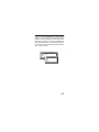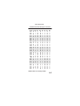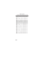
1
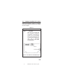
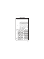
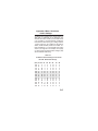
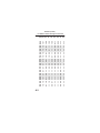
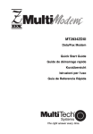
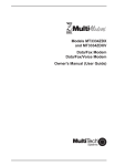
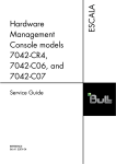
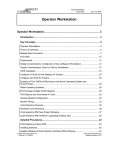
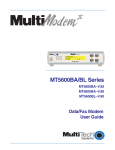
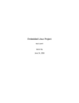
MultiTech Systems Intelligent Serial Interface Model ISI551PC Card (ISI) Owner's Manual 82031702 NOTE: This equipment has been tested and found to comply with the limits for a Class B digital device, pursuant to Part 15 of the FCC Rules. These limits are designed to provide reasonable protection against harmful interference when the equipment is operated in a residential installation. This equipment generates, uses and can radiate radio frequency energy, and if not installed and used in accordance with the instruction manual, may cause harmful interference to radio communications. However, there is no guarantee that interference will not occur in a particular installation. If this equipment cause harmful interference to radio or television reception, which can be determined by turning the equipment off and on, the user is encouraged to try to correct the interference by one or more of the following measures: Reorient or relocate the receiving antenna. Increase the separation between the equipment and receiver. Connect the equipment into an outlet on a circuit different from that of which the receiver is connected. Consult the dealer or an experienced radio/TV technician for help. WARNING: Changes or modifications to this unit not expressly approved by the party responsible for compliance could void the users authority to operate this equipment. This device complies with Part 15 of the FCC rules. Operation is subject to the following conditions: (1) This device may not cause harmful interference, and (2) this device must accept any interference received, including interference that may cause undesired operation. Owner's Manual P/N 82031702, Rev. C ISI551PC This publication may not be reproduced, in whole or in part, without prior expressed written permission from Multi-Tech Systems, Inc.. All rights reserved. Copyright © 1995, by Multi-Tech Systems, Inc. Multi-Tech Systems, Inc., makes no representation or warranties with respect to the contents hereof and specifically disclaims any implied warranties of merchantability or fitness for any particular purpose. Furthermore, Multi-Tech Systems, Inc., reserves the right to revise this publication and to make changes from time to time in the content hereof without obligation of Multi-Tech Systems, Inc., to notify any person or organization of such revisions or changes. Record of Revision C Manual revised with format and editorial (2/6/95) changes TRADEMARKS Multi-Tech, MultiExpress, MultiModemII and the Multi-Tech logo: Multi-Tech Systems, Inc. i386, i486: Intel Corporation PC-DOS: International Business Machines Corporation Multi-Tech Systems, Inc. 2205 Woodale Drive Mounds View, Minnesota 55112 U.S.A. (612) 785-3500 or (800) 328-9717 U. S. FAX 612-785-9874 Technical Support (800) 972-2439 BBS (612) 785-3702 or (800) 392-2432 Internet Address: http://www.multitech.com TABLE OF CONTENTS 1.1 1.2 1.3 1.4 CHAPTER 1 INTRODUCTION & DESCRIPTION Introduction ........................................... 1-1 Product Description .............................. 1-2 How to Use This Manual ...................... 1-2 Technical Specifications ...................... 1-3 2.1 2.2 2.3 CHAPTER 2 HARDWARE INSTALLATION ISI Card Installation .............................. 2-1 Determining Current System Settings . 2-1 Hardware Installation Procedure .......... 2-3 CHAPTER 3 SERVICE, WARRANTY, AND TECHNICAL SUPPORT 3.1 Introduction ........................................... 3-1 3.2 Limited Warranty .................................. 3-1 3.3 Tech Support ........................................ 3-2 3.3.1 Recording ISI551PC Information 3-3 3.3.2 Service ........................................ 3-4 3.4 About the Multi-Tech BBS .................... 3-5 3.4.1 How to Use the Multi-Tech BBS . 3-6 3.5 About CompuServe/Internet ................ 3-7 Appendix A: I/O Address Switch Settings A-1 i 1.1 Introduction The introduction of high speed, data compression modems, such as Multi-Tech's MultiModem II TM Series, has shown that many PC serial ports are unable to keep up, essentially becoming a bottleneck for the entire system. The ISI551PC card provides processing power to reliably transmit data up to 115.2K bps. Using an ISI enables your system's processor to perform more efficiently. This is because the ISI handles all of the byte-by-byte interrupts generated by the asynchronous terminals and stores the data in buffers. The ISI then generates one interrupt for an entire block of information and transfers the block to the system's microprocessor. This manual provides the hardware installation procedures for the ISI551PC card. The ISI551PC card is used with Multi-Tech's high speed modems; and is a high speed, buffered, single-port serial card, with its own on board processor. The operation of the card provides the basis for its name ISI (Intelligent Serial Interface), 551 indicating the processing power of a 16550A UART and one port support, and PC indicating that it is an ISA bus card (8 bit), which is able to operate in any 286, 386, 486 or Pentium ISA or EISA compatible bus personal computer. The ISI551PC card can be accessed by any software written to the 16550A specification. 1-1 This manual contains product specifications, installation instructions, configuration and technical support information which will assist you in the operation process. It is assumed that you have basic PC skills at the very least. Therefore, we have not included step-by-step instructions for basic operations such as logging in and file editing, etc. 1.2 Product Description The ISI551PC card is a single port serial expansion card which adds data buffering for enhanced serial port performance. The ISI551PC features a 9-pin connector (one DB-9), and is a "half-size" expansion card that supports a high-speed interface (up to 115.2K bps via 32K bytes of RAM). The ISI551PC features a bank of 8 DIP-Switches for I/O address selection and one jumper block for IRQ level selection. 1.3 How to Use This Manual This chapter begins with a short introduction, product description, followed by a guide (which you are now reading) to the use of this manual, as well as the ISI551PCs technical specifications. 1-2 This manual includes hardware configuration and installation procedures described in Chapter 2. Chapter 3 covers technical support, warranty and BBS information. Appendix A describes complete information on Base I/O addressing. 1.4 Technical Specifications Computer Requirements · 286-, 386- or 486- based PC or compatible Operating Temperature · 0° to 50°C (32° to 120°F) Serial Interface · RS232C, RS232D Bus Type · IBM PC standard (ISA bus) or EISA Power Consumption · 750 mAmps @ +5 VDC · 100 mAmps @ +12 VDC · 100 mAmps @ -12 VDC 1-3 Card Dimensions ISI551PC · 4.95" L x 2.375" W x .062" D · 12.5 cm L x 6.0 cm W x .16 cm D Baud Rates · Up to 115.2K bps Connector Types · One DB-9 on ISI551PC I/O Address · Set by hardware DIP-Switch, valid range 100H to 3F8H (See Appendix A) Interrupt Request · Set by hardware Jumper, valid IRQs -- 2, 3, 4, 5, 7, 10, 11, 12, & 15 1-4 2.1 ISI Card Installation This chapter provides you with the procedures to install the Multi-Tech ISI551PC card in your ISA or EISA bus personal computer. Hardware installation involves: 1) Opening your PC. 2) Setting card configuration (determining I/O address DIP-Switch setting and IRQ jumper setting). 3) Installing the card into the PC. 2.2 Determining Current System Settings When you install a serial device into your computer, the processor must have a means of routing information to and from the device and the device must have a means of gaining the processor's attention. These are called Input/Output (I/O) addresses and Interrupt Requests (IRQs), respectively. The ISI551PC card requires eight I/O addresses and one IRQ value which are not used by any other device in your system. When selecting a unique base I/O address, be sure that the other addresses are also unused. (For example, if you 2-1 use the base I/O address of 380h, addresses 380h387h must be unused.) To select an unused I/O address and an IRQ value, it may be necessary to find out which values are already in use. To determine your system's current settings, refer to Appendix A. The ISI551PC is shipped with the IRQ set to level 3 and the base I/O address at 2F8 hex. If you are certain that these settings are not already in use, continue with the hardware configuration and installation. Note: If you choose IRQ 3 or 4, you may have to remove the serial I/Odevice from your configuration files. The ISI551PC cards do not allow you to select IRQ 6 because it is almost universally used for the floppy drive of a computer. Also, most computers will not be able to assign IRQ 2 to the ISI because IRQ 2 is used for slave control. 2-2 2.3 Hardware Installation Procedure Perform the procedures in Table 2-1 to configure and install the ISI551PC card into your ISA or EISA bus host computer. Table 2-1 ISI Configuration and Installation Procedure Step 1 Procedure Make sure your computer and any peripheral equipment connected to it, are turned off. Failure to do so may damage both your ISI card and your PC. The card may be installed in any 286-, 386- or 486-based computer with an ISA or EISA bus architecture. Figure 2-1. I/O Address Switch/IRQ Jumpers 2-3 2 Remove the cover of your Table 2-1 (cont'd) ISI Configuration and Installation Procedure Step Procedure computer as instructed in your computers documentation. 3 Locate the unused slot(s) which you will be using for your ISI card, and remove the slot cover(s) per the instructions in your computers documentation. 4a The figure below shows the default settings for this card. Record any changes made to the Base I/O Address settings. The default Base I/O Address is 2F8 (COM2). The valid range is 100H - 3F8 H; refer to Appendix A for a full table of address settings. O(pen) = OFF C(losed) = ON Figure 2-2. I/O Address Default 2-4 Table 2-1 (cont'd) ISI Configuration and Installation Procedure Step Procedure 4b Select a unique I/O Address for your ISI551PC card using the block of 8-position DIP-Switches on your ISI circuit board. Figure 2-3 shows various I/O addressing and IRQ settings. 5 Record any changes you make to these settings and keep them handy for the driver installation. Com Port I/O Address Setting IRQ Level COM1 COM2 COM3 COM4 Figure 2-3. I/O Address and IRQ Level Settings 2-5 Table 2-1 (cont'd) ISI Configuration and Installation Procedure Step Procedure 6 Install the ISI card into the selected expansion slot(s) in the same manner as any other add-on card, as instructed in your computers documentation. 7 Fasten the retaining bracket to the computer chassis and replace the cover. 8 Connect the appropriate cable to the ISI card. The ISI551PC has one DB-9 connector. The DB-9 is a DTE-type serial port suited for the connection of Data Circuitterminating Equipment, or DCEs. Note: Any cables connected to the computer should be shielded to reduce interference. 9 2-6 Turn power on to your computer. If you are using MultiExpress communication software, note during your communication set-up that your ISI card is activated by choosing Serial and then Comm port selection. Do not use the MultiTech ISI selection for this card. The MultiTech ISI selection is used with ISI models ISI502 and ISI508, which are older legacy products. 2-7 3.1 Introduction This chapter starts out with statements about your ISI551PC's 2-year warranty. The next section, Tech Support, should be read carefully if you have questions or problems with your ISI551PC. It includes the technical support telephone numbers, space for recording your ISI551PC information, and an explanation of how to send in your ISI551PC should you require service. The final two sections explain how to use our Bulletin Board Service (BBS), and a brief section on the CompuServe/Internet forums. 3.2 Limited Warranty Multi-Tech Systems, Inc. (MTS) warrants that its products will be free from defects in material or workmanship for a period of two years from the date of purchase, or if proof of purchase is not provided, two years from date of shipment. MTS MAKES NO OTHER WARRANTY, EXPRESSED OR IMPLIED, AND ALL IMPLIED WARRANTIES OF MERCHANTABILITY AND FITNESS FOR A PARTICULAR PURPOSE ARE HEREBY DISCLAIMED. This warranty does not apply to any products which have been damaged by lightning storms, water, or power surges or 3-1 which have been neglected, altered, abused, used for a purpose other than the one for which they were manufactured, repaired by the customer or any party without MTSs written authorization, or used in any manner inconsistent with MTSs instructions. MTSs entire obligation under this warranty shall be limited (at MTSs option) to repair or replacement of any products which prove to be defective within the warranty period, or, at MTSs option, issuance of a refund of the purchase price. Defective products must be returned by Customer to MTSs factory transportation prepaid. MTS WILL NOT BE LIABLE FOR CONSEQUENTIAL DAMAGES AND UNDER NO CIRCUMSTANCES WILL ITS LIABILITY EXCEED THE PURCHASE PRICE FOR DEFECTIVE PRODUCTS. 3.3 Tech Support Multi-Tech has an excellent staff of technical support personnel available to help you get the most out of your Multi-Tech product. If you have 3-2 any questions about the operation of this unit, call 1-800-972-2439. Please fill out the ISI551PC information (below), and have it available when you call. If your ISI551PC requires service, the tech support specialist will guide you on how to send in your ISI551PC (see Section 3.3.2). 3.3.1 Recording ISI551PC Information Please fill in the following information on your Multi-Tech ISI551PC. This will help tech support in answering your questions. ISI551PC Model No.: ISI551PC Serial No.: ISI551PC Firmware Version: DataComm Software Type/Version: Please note the status of your ISI551PC before calling tech support. 3-3 3.3.2 Service If your tech support specialist decides that service is required, ISI551PCs may be sent (freight prepaid) to our factory. Return shipping charges will be paid by Multi-Tech Systems. Include the following with your ISI551PC: a description of the problem. return billing and return shipping addresses. contact name and phone number. check or purchase order number for payment if the ISI551PC is out of warranty. (The standard repair charge for this ISI551PC is $95. This price is valid at the time of this publication but could change in the future. Check with your technical support specialist.) if possible, note the name of the technical support specialist with whom you spoke. If you need to inquire about the status of the returned product, be prepared to provide the serial number of the product sent (see Section 3.3.1). 3-4 Send ISI551PCs to this address: MULTI-TECH SYSTEMS, INC. 2205 WOODALE DRIVE MOUNDS VIEW, MINNESOTA 55112 ATTN: SERVICE OR REPAIRS You should also check with the supplier of your ISI551PC on the availability of local service and/or loaner units in your part of the country. You may call us at 1-800-328-9717 or (612) 785-3500 (in Minnesota). 3.4 About the Multi-Tech BBS Multi-Tech Systems maintains a Bulletin Board Service (BBS) for its customers. The information available via the BBS includes: new product information, product upgrade data, problem solving tips, and a message service for you to leave questions for which you would like additional information. The phone number for the Multi-Tech BBS is (612) 785-9875 or (800) 3922432 (U.S.A. and Canada). The BBS can be accessed by any asynchronous modem operating at 28,800-1200 bps with a setting of 8 bits, 1 stop bit, and no parity (V.34 and downward compatible). 3-5 3.4.1 How to Use the Multi-Tech BBS To use Multi-Tech's BBS, perform the following steps. 1. Dial our BBS at 1-800 392-2432 (U.S.A. and Canada) or 612-785-9875 (International). 2. Set your computer or communications program to "8N1", and to emulate ANSI (e.g., with MultiExpress software, press ALT-S and choose "ANSI"). 3. At the prompt, type your first name, last name, password, then hit RETURN. If you are a first time caller, after you hit RETURN the BBS asks if your name is spelled correctly. If you say yes, our questionnaire is displayed. You can use our BBS on your first call. 4. There are four BBS areas: the Main Menu, the Files Menu, Bulletins (from the main Menu), and the Message Menu. All Bulletins are Menu-driven. To read the Bulletins, enter the number of the bulletin you wish to read. 5. File Menu: from the Main Menu, type F: and the Files are displayed. If you want a list of directories, type L (list directory) and then type L again for a list of all directories. If you do not type the second L, you will list all of 3-6 the files on the BBS. At the list of the directories, select the number of directories required. A list of files and a description for each of the files is displayed. Select a file that you would like to download; if you already know the file name, type D at the Files Menu to download the selected file(s). Pess V to view a text file. 6. At the Message Menu, you can leave a message to the Sysop (you can not read messages at this point). The BBS will tell you if you have a personal message (mail). At the prompt (would you like to read it now?), type R for read now. You must read your message(s) when you first access the BBS. 3.5 About CompuServe/Internet In addition to the BBS, Multi-Tech provides support through CompuServe's Modem Vendor Forum (GOMODEMVEN) under GO MULTITECH. Refer to your CompuServe documentation for special operating procedures. 3-7 Multi-Tech is a commercial user of the Internet, and messages are retrieved from our customers on a periodic basis. If you prefer receiving technical support viathe Internet, plaese address your message to: [email protected]. Multi Tech also maintains a home page on the World Wide Web at the following address: http://www.multitech.com Multi Tech also maintains a FTP Server at the following address: FTP.multitech.com 3-8 Appendix A Base I/O Address Switch Settings The table below provides the DIP-Switch settings for valid base I/O addresses of the ISI551PC. The switches can be set to "OPEN" (O in the table below) or to "CLOSED" (C in the table below). Holding the board with the switch facing you (reading numbers 1-8 left to right), the "UP" position for the switch is OPEN, and the "DOWN" position is CLOSED. "S1" below is labeled as "1" on the left side of the switch and so on, through S8. For an example, turn to page A-3 and compare the default switch settings (2F8) with the address 380h listing. Table A-1 I/O Address Switch Settings for ISI Cards I/O Addr. DIP-Switch Settings (hex) S1 S2 S3 100 108 110 118 120 128 130 138 140 148 150 158 160 168 C O C O C O C O C O C O C O C C O O C C O O C C O O C C C C C C O O O O C C C C O O S4 S5 C C C C C C C C O O O O O O C C C C C C C C C C C C C C S6 S7 S8 O O O O O O O O O O O O O O C C C C C C C C C C C C C C C C C C C C C C C C C C C C A-1 Table A-1(cont'd) I/O Address Switch Settings for ISI Cards (hex) S1 S2 S3 170 178 180 188 190 198 1A0 1A8 1B0 1B8 1C0 1C8 1D0 1D8 1E0 1E8 1F0 1F8 200 208 210 218 220 228 230 238 240 248 250 A-2 C O C O C O C O C O C O C O C O C O C O C O C O C O C O C O O C C O O C C O O C C O O C C O O C C O O C C O O C C O O O C C C C O O O O C C C C O O O O C C C C O O O O C C C S4 S5 O O C C C C C C C C O O O O O O O O C C C C C C C C O O O C C O O O O O O O O O O O O O O O O C C C C C C C C C C C S6 S7 S8 O O O O O O O O O O O O O O O O O O C C C C C C C C C C C C C C C C C C C C C C C C C C C C C O O O O O O O O O O O C C C C C C C C C C C C C C C C C C C C C C C C C C C C C Table A-1(cont'd) I/O Address Switch Settings for ISI Cards (hex) 258 260 268 270 278 280 288 290 298 2A0 2A8 2B0 2B8 2C0 2C8 2D0 2D8 2E0 2E8 2F0 *2F8 300 308 310 318 320 328 330 338 340 S1 S2 S3 S4 O O C O C C O O O C O O C O O O O O O O C C C C O C C C C O C C O O C C C C O C O C O C C O O C O O O C C C C O O C C O C O C O O O C O C C O O O C O O C O O O O O O O C C C C O C C C C O C C O O C C C C O C O C O C C O O C O O O C C C C O S5 C C C C C O O O O O O O O O O O O O O O O C C C C C C C C C S6 S7 C O C O C O C O C O C O C O C O C O C O C O C O C O C O C O C O C O C O C O C O C O O O O O O O O O O O O O O O O O O O *Address 2F8 is the Factory Default S8 C C C C C C C C C C C C C C C C C C C C C C C C C C C C C C A-3 Table A-1(cont'd) I/O Address Switch Settings for ISI Cards (hex) S1 S2 S3 S4 S5 S6 S7 S8 348 350 358 360 368 370 378 380 388 390 398 3A0 3A8 3B0 3B8 3C0 3C8 3D0 3D8 3E0 3E8 3F0 3F8 O O O O O O O C C C C C C C C O O O O O O O O C C C C C C C O O O O O O O O O O O O O O O O O O O O O O O O O O O O O O O O O O O O O O O A-4 O C O C O C O C O C O C O C O C O C O C O C O C O O C C O O C C O O C C O O C C O O C C O O C C C O O O O C C C C O O O O C C C C O O O O O O O O O O O O O O O O O O O O O O O O O O O C C C C C C C C C C C C C C C C C C C C C C C Index A About CompuServe ........................... 3-7 About the Multi-Tech BBS .................. 3-5 B Base I/O Switch Settings ................... A-1 Baud Rates ...................................... 1-4 Bus Type ...................................... 1-3 C Card Dimensions .............................. CompuServe .................................... Computer Requirements ................... Connector Types ............................... 1-4 3-7 1-3 1-4 H Hardware Installation Procedure ........ 2-3 How to Use the Multi-Tech BBS .......... 3-6 How to Use This Manual .................... 1-2 1-Index I I/O Address ....................................... I/O Address Switch and IRQ Jumper Locations .................................. Introduction ....................................... ISI Card Installation ............................ 1-4 2-3 1-1 2-1 L Limited Warranty ............................... 3-1 M Multi-Tech BBS ................................. 3-5 O Operating Temperature ...................... 1-3 P Power Consumption .......................... 1-3 Product Description ........................... 1-2 R Recording ISI551PC Information ........ 3-3 2-Index S Serial Interface ................................ 1-3 Service ............................................. 3-4 T Tech Support .................................... 3-2 Technical Specifications ..................... 1-3 W Warranty ........................................... 3-1 3-Index