1
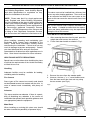
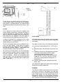
BERRINGTON
SOLID FUEL BOILER
STOVE
INSTALLATION AND OPERATING INSTRUCTIONS
This appliance is hot while in operation and retains its heat for a long period of time after use. Children, aged
or infirm persons should be supervised at all times and should not be allowed to touch the hot working surfaces
while in use or until the appliance has thoroughly cooled.
PLEASE READ THESE INSTRUCTIONS CAREFULLY BEFORE INSTALLATION. These instructions cover
the basic principles to ensure the satisfactory installation of the stove, although detail may need slight
modification to suit particular local site conditions.
TABLE OF CONTENTS
PAGE NO.
1.
General . . . . . . . . . . . . . . . . . . . . . . . . . . . . . . . . . . . . . . . . . . . . . . . . . . . . . . . . . . . . . .
3
2.
Health & Safety Precautions . . . . . . . . . . . . . . . . . . . . . . . . . . . . . . . . . . . . . . . . . . . . . .
3
Handling . . . . . . . . . . . . . . . . . . . . . . . . . . . . . . . . . . . . . . . . . . . . . . . . . . . . . . . . .
3
Fire Cement . . . . . . . . . . . . . . . . . . . . . . . . . . . . . . . . . . . . . . . . . . . . . . . . . . . . . .
3
Asbestos . . . . . . . . . . . . . . . . . . . . . . . . . . . . . . . . . . . . . . . . . . . . . . . . . . . . . . . . .
3
Metal Parts . . . . . . . . . . . . . . . . . . . . . . . . . . . . . . . . . . . . . . . . . . . . . . . . . . . . . . .
3
3.
Pre Installation Assembly . . . . . . . . . . . . . . . . . . . . . . . . . . . . . . . . . . . . . . . . . . . . . . . . .
3
4.
Flues . . . . . . . . . . . . . . . . . . . . . . . . . . . . . . . . . . . . . . . . . . . . . . . . . . . . . . . . . . . . . . . .
4
5.
Flue Pipes . . . . . . . . . . . . . . . . . . . . . . . . . . . . . . . . . . . . . . . . . . . . . . . . . . . . . . . . . . . .
4
6.
Chimney . . . . . . . . . . . . . . . . . . . . . . . . . . . . . . . . . . . . . . . . . . . . . . . . . . . . . . . . . . . . . .
4
7.
Down Draughts . . . . . . . . . . . . . . . . . . . . . . . . . . . . . . . . . . . . . . . . . . . . . . . . . . . . . . . .
5
8.
Ventilation & Combustion Air Requirements . . . . . . . . . . . . . . . . . . . . . . . . . . . . . . . . . .
5
9.
Permanent Air . . . . . . . . . . . . . . . . . . . . . . . . . . . . . . . . . . . . . . . . . . . . . . . . . . . . . . . . .
5
Extractor Fan. . . . . . . . . . . . . . . . . . . . . . . . . . . . . . . . . . . . . . . . . . . . . . . . . . . . . .
5
10.
Commissioning & Handover . . . . . . . . . . . . . . . . . . . . . . . . . . . . . . . . . . . . . . . . . . . . . .
5
11.
Flue Pipes . . . . . . . . . . . . . . . . . . . . . . . . . . . . . . . . . . . . . . . . . . . . . . . . . . . . . . . . . . . .
6
12.
Top Flue Exit . . . . . . . . . . . . . . . . . . . . . . . . . . . . . . . . . . . . . . . . . . . . . . . . . . . . . . . . . .
6
13.
Rear Flue Exit . . . . . . . . . . . . . . . . . . . . . . . . . . . . . . . . . . . . . . . . . . . . . . . . . . . . . . . . .
6
14.
Floor Protection . . . . . . . . . . . . . . . . . . . . . . . . . . . . . . . . . . . . . . . . . . . . . . . . . . . . . . . .
6
15.
Location . . . . . . . . . . . . . . . . . . . . . . . . . . . . . . . . . . . . . . . . . . . . . . . . . . . . . . . . . . . . . .
7
16.
Installation Clearances . . . . . . . . . . . . . . . . . . . . . . . . . . . . . . . . . . . . . . . . . . . . . . . . . .
7
17.
Specification . . . . . . . . . . . . . . . . . . . . . . . . . . . . . . . . . . . . . . . . . . . . . . . . . . . . . . . . . . .
7
18.
Technical Data . . . . . . . . . . . . . . . . . . . . . . . . . . . . . . . . . . . . . . . . . . . . . . . . . . . . . . . . .
7
19.
Plumbing . . . . . . . . . . . . . . . . . . . . . . . . . . . . . . . . . . . . . . . . . . . . . . . . . . . . . . . . . . . . .
8
20.
Regulations . . . . . . . . . . . . . . . . . . . . . . . . . . . . . . . . . . . . . . . . . . . . . . . . . . . . . . . . . . .
8
21.
Gravity Circuit. . . . . . . . . . . . . . . . . . . . . . . . . . . . . . . . . . . . . . . . . . . . . . . . . . . . . . . . . .
8
22.
Injector Tee. . . . . . . . . . . . . . . . . . . . . . . . . . . . . . . . . . . . . . . . . . . . . . . . . . . . . . . . . . . .
8
23.
Water Circuit Temperature . . . . . . . . . . . . . . . . . . . . . . . . . . . . . . . . . . . . . . . . . . . . . . . .
8
24.
Operating Instructions . . . . . . . . . . . . . . . . . . . . . . . . . . . . . . . . . . . . . . . . . . . . . . . . . . .
8
25.
Primary Air Control. . . . . . . . . . . . . . . . . . . . . . . . . . . . . . . . . . . . . . . . . . . . . . . . . . . . . .
9
26.
Low / Slumber Burn . . . . . . . . . . . . . . . . . . . . . . . . . . . . . . . . . . . . . . . . . . . . . . . . . . . . .
9
27.
Recommended Fuels . . . . . . . . . . . . . . . . . . . . . . . . . . . . . . . . . . . . . . . . . . . . . . . . . . . .
9
28.
Important Notes . . . . . . . . . . . . . . . . . . . . . . . . . . . . . . . . . . . . . . . . . . . . . . . . . . . . . . . .
10
29.
Lighting. . . . . . . . . . . . . . . . . . . . . . . . . . . . . . . . . . . . . . . . . . . . . . . . . . . . . . . . . . . . . . .
11
30.
De-Ashing . . . . . . . . . . . . . . . . . . . . . . . . . . . . . . . . . . . . . . . . . . . . . . . . . . . . . . . . . . . .
12
31.
Disposal of Ashes . . . . . . . . . . . . . . . . . . . . . . . . . . . . . . . . . . . . . . . . . . . . . . . . . . . . . .
12
32.
To Clean Chimney Outlet . . . . . . . . . . . . . . . . . . . . . . . . . . . . . . . . . . . . . . . . . . . . . . . . .
12
33.
To Replace Damaged Grate or Bar . . . . . . . . . . . . . . . . . . . . . . . . . . . . . . . . . . . . . . . . .
12
34.
Periods of Prolonged Non-Use . . . . . . . . . . . . . . . . . . . . . . . . . . . . . . . . . . . . . . . . . . . .
13
35.
Fire Safety . . . . . . . . . . . . . . . . . . . . . . . . . . . . . . . . . . . . . . . . . . . . . . . . . . . . . . . . . . . .
13
36.
In Case of Fire . . . . . . . . . . . . . . . . . . . . . . . . . . . . . . . . . . . . . . . . . . . . . . . . . . . . . . . . .
13
1
TABLE OF CONTENTS
PAGE NO.
37.
Vitreous Enamel Cleaning . . . . . . . . . . . . . . . . . . . . . . . . . . . . . . . . . . . . . . . . . . . . . . . .
13
38.
Glass Cleaning. . . . . . . . . . . . . . . . . . . . . . . . . . . . . . . . . . . . . . . . . . . . . . . . . . . . . . . . .
13
39.
Glass Replacement . . . . . . . . . . . . . . . . . . . . . . . . . . . . . . . . . . . . . . . . . . . . . . . . . . . . .
13
40.
Exploded View . . . . . . . . . . . . . . . . . . . . . . . . . . . . . . . . . . . . . . . . . . . . . . . . . . . . . . . . .
14
2
BERRINGTON SOLID FUEL STOVE INSTALLATION & OPERATING INSTRUCTIONS
IMPORTANT WARNING
In all cases the installation must comply with current Building Regulations, Local Authority Bylaws
and other specifications or regulations as they
affect the installation of the stove.
This stove must not be installed into a chimney that
serves any other heating appliance. There must not
be an extractor fan fitted in the same room as the
stove as this can cause the stove to emit fumes into
the room.
NOTE: Please note that it is a legal requirement
under England and Wales Building Regulations
that the installation of the stove is either carried out
under Local Authority Building Control approval or
is installed by a Competent Person registered with
a Government approved Competent Persons
Scheme. HETAS Ltd operate such a Scheme and
a listing of their Registered Competent Persons
can be found on their website at www.hetas.co.uk.
The installation must be completed in accordance
with current National and European Standards and
Local Codes. It should be noted that the requirements and these publications may be superseded
during the life of this manual.
PRE INSTALLATION ASSEMBLY
GENERAL
1. After removing the stove from its pack, open the
ashpit door and remove the contents.
2. Fit the front door handle as shown in Fig.1.
When installing, operating and maintaining your
Berrington Stove respect basic standards of fire
safety. Read these instructions carefully before
commencing the installation. Failure to do so may
result in damage to persons and property. Consult
your local Municipal office and your insurance
representative to determine what regulations are in
force. Save these instructions for future reference.
Fig.1
HEALTH AND SAFETY PRECAUTIONS
Special care must be taken when installing the stove
such that the requirements of the Health and Safety
at Work Act are met.
Handling
Adequate facilities must be available for loading,
unloading and site handling.
3. Remove the stove from the wooden pallet.
4. Unscrew the two 1/4” x 1/2” round head screws
from the base and fit the front ash tray using
the two screws (see Fig.2).
Fire Cement
Some types of fire cement are caustic and should
not be allowed to come into contact with the skin. In
case of contact wash immediately with plenty of
water.
Fig.2
Asbestos
This stove contains no asbestos. If there is a possibility of disturbing any asbestos in the course of
installation then please seek specialist guidance and
use appropriate protective equipment.
Metal Parts
When installing or servicing this stove care should
be taken to avoid the possibility of personal injury.
3
Fig.4
2300
600
Fig.3
Fit the primary air control knob to the flexible drive.
(for the boiler model, ensure that the air damper
knob spacer is placed between the knob and the
flexible drive bracket on the back of the boiler). See
Fig.3
FLUES
Appliance
Flues should be vertical wherever possible and
where a bend is necessary, it should not make an
angle of more than 45o with the vertical. Horizontal
flue runs should be avoided except in the case of a
back outlet from the appliance, when the length of
the horizontal section should not exceed 150mm.
Soot Door
FLUE PIPES
In order to minimise flue resistance and to make
sweeping easier it is recommended to use 2 x 45o
bends rather than a 90o bend.
A flue pipe should only be used to connect an appliance to a chimney and should not pass through any
roof space.
The flue termination point must be located to minimise any wind effects. Wind effects of suction,
pressure zones and turbulence can be created by
the roof and adjacent objects. Wind effects can
also be created by natural land contours.
Flue pipes may be of any of the following materials:
(a) Cast iron as described in BS 41: 1973 (1981),
or
(b) Mild steel with a wall thickness of at least 3mm,
or
(c) Stainless steel with a wall thickness of at least
1mm and as described in BS EN 10095:
1999 Specification for stainless and
heat resisting steel plate, sheet and strip, for
Grade 316 S11, 316 S13, 316 S16, 316 S31,
316 S33, or the equivalent Euronorm 88-71
designation, or
(d) Vitreous enamelled steel complying with BS
6999: 1989.
To minimise the wind effects, the flue termination
point should be located a minimum of 600mm from
the roof measured vertically and 2300mm measured horizontally. Where this termination point
does not suffice it may be necessary to extend the
flue pipe so that the termination point is above the
apex. (See Fig.3)
Flue pipes with spigot and socket joints should be
fitted with the socket uppermost.
CHIMNEY
The stove is a radiant room heater and must be connected to a chimney of the proper size and type.
The chimney must have a cross sectional area of at
least 19350 square mm (30 square inches) or a
diameter of 150mm (6 “). The chimney should be
checked for soundness and draught before installation. The stove must be connected to a chimney
4
with a minimum continuous draught of 15 Pascals.
Poor draught will result in poor performance.
Similarly an excessive draught will result in the appliance over firing or being difficult to control. An
excessive draught may require a flue draught stabiliser to be fitted. Do not connect this appliance to a
chimney serving another appliance. The minimum
required chimney height is 4.5 metres from the floor
on which the appliance is installed. An existing
masonry chimney should be inspected and if necessary, repaired by a competent mason.
Air vents direct to the outside of the building should
be located so that any air current produced will not
pass through normally occupied areas of the room.
An air vent outside the building should not be located less than the dimensions specified within the
Building Regulations from any part of any flue terminal. These air vents must also be fire proofed as per
Building Regulations.
Air vents traversing cavity walls should include a
continuous duct across the cavity. The duct should
be installed in such a manner as not to impair the
weather resistance of the cavity. Joints between air
vents and outside walls should be sealed to prevent
the ingress of moisture. Existing air vents should be
of the correct size and unobstructed for the appliance in use. If there is an air extraction fan or other
air using appliance fitted in the room or adjacent
rooms where this appliance is fitted, additional air
vents will be required to alleviate the possibility of
spillage of products of combustion from the appliance/flue while the fan is in operation.
If the stove is fitted in place of an open fire then the
chimney should be swept one month after installation to clear any soot falls which may have occurred
due to the difference in combustion between the
stove and the open fire.
DOWN DRAUGHTS
However well designed constructed and positioned,
the satisfactory performance of the flue can be
adversely affected by down draught caused by nearby hills, adjacent tall buildings or trees. These can
deflect wind to blow directly down the flue or create
a zone of low pressure over the terminal. A suitable
anti-down draught terminal or cowl will usually effectively combat direct down blow but no cowl is likely
to prevent down draught due to a low pressure zone.
Where such an installation exists, a test for spillage
should be made with the fan or fans and other appliances using air in operation at full rate, (i.e. extraction fans, tumble dryers) with all external doors and
windows closed. If spillage occurs following the
above operation, an additional air vent of sufficient
size to prevent this occurrence should be installed.
VENTILATION & COMBUSTION AIR
REQUIREMENTS
PERMANENT AIR VENT
This appliance is rated at no more than 8kW. It is
imperative that there is sufficient air supply to the
stove in
order to support correct combustion. The air supply
to this appliance must comply with B.S. 8303: Part 1
and current Building Regulations. The minimum
effective air requirement for this appliance is
16.5cm2.
The stove requires an adequate air supply in order
for it to operate safely and efficiently. The installer
may have fitted a permanent air supply vent into the
room in which the stove is installed to provide combustion and/or ventilation air. This air vent should
not under any circumstances be shut off or sealed.
If a draught stabiliser is used then this increases to
40.5cm2. When calculating combustion air requirement for this appliance use the following equation: a
total free area of at least 550mm2 per kW of rated
output above 5kW shall be provided. If there is
another air using appliance fitted in the same or
adjacent room, it will be necessary to calculate additional air supply. All materials used in the manufacture of air vents should be such that the vent is
dimensionally stable and corrosion resistant.
There must not be an extractor fan fitted in the same
room as the stove as this can cause the stove to
emit smoke and fumes into the room.
Extractor Fan
COMMISSIONING AND HANDOVER
Ensure all parts are fitted in accordance with the
instructions.
On completion of the installation allow a suitable
period of time for any fire cement and mortar to dry
out, before lighting the stove. Once the stove is
under fire check all seals for soundness and that the
boiler and water system are operating correctly.
Ensure that the flue is functioning correctly and that
all products of combustion are vented safely to
atmosphere via the chimney terminal.
The effective free area of any vent should be ascertained before installation. The effect of any screen
should be allowed for when determining the effective
free area of any vent.
5
On completion of the installation and commissioning
ensure that the operating instructions for the stove
are left with the customer. Ensure to advise the customer on the correct use of the appliance and warn
them to use only the recommended fuels for the
stove.
Fig. 6
Advise the user what to do should smoke or fumes
be emitted from the stove. The customer should be
warned to use a fireguard to BS 6539 in the presence of children, aged and/or infirm persons.
FLUE PIPES
Flue pipes with spigot and socket joints should be
fitted with the socket upper most. Clearance to
combustibles must be adhered to when fitting the
flue pipe. The connecting flue pipe must not be
less than the diameter of the stove outlet. The flue
gas mass flow is 5.4 g/s mineral fuel and 6.1 g/s
wood logs. The mean flue gas temperature directly
downstream of the spigot at nominal heat output is
262°C. The appliance is suitable for continuous
operation on solid mineral fuel and intermittent
operation on wood logs.
It may be necessary to have an inspection plate in
the flue pipe to assist with access for cleaning the
flue way.
FLOOR PROTECTION
It is recommended that this appliance is installed on
a solid, level, non combustible hearth conforming to
current Building Regulations.
TOP FLUE EXIT
Fig.7
For the top outlet configuration, connect bend (not
supplied) into flue outlet socket at the rear of the
stove and cement into place using approved fire
cement ensuring that no cement blocks the flue
passageway. (See Fig. 6)
Fig. 5
6” Cast Iron
Bend
The appliance is suitable for continuous operation
on solid mineral fuel and intermittent operation on
wood logs. This appliance has been tested using
seasoned wood logs and manufactured briquetted
smokeless fuel (Ancit) for closed appliances, sized
between 20g and 140g. Other fuels are commercially available. Wood logs up to 400 mm long are
suitable. All fuels should be stored under cover and
kept as dry as possible prior to use.
REAR FLUE EXIT
For the rear flue outlet configuration, push in the flue
connector pipe (not supplied) into the flue outlet
socket at the rear of the stove and cement into place
using approved fire cement ensuring that no cement
blocks the flue passageway. (See Fig.7)
6
LOCATION
INSTALLATION CLEARANCES
There are several conditions to be considered in
selecting a location for your Berrington Stove.
Maintain at least the following clearances to all
combustible material:
From the front
900 mm
From the Sides
150 mm
From the rear
150 mm
From the flue pipe
600 mm
a. Position in the area to be heated- central
locations are usually best.
b. Allowances for proper clearances to
combustibles.
Note: Sufficient space should be given around
the back and sides of the stove to allow
access to the air control damper.
SPECIFICATION
Fig 8
NOTE: Dimensions stated are in millimeters and may be subject to a slight +/- variation.
SPECIFICATIONS
Depth
Flue Outlet
Fire Door Size
Log Size
TECHNICAL DATA
Metric
495mm
152mm
455x230mm
400mm
Boiler Tapping: 1” BSP
Boiler Capacity: 12.7 Litres
Maximum Operating Water Pressure 2.0 Bar
Nominal Output: Wood Logs Solid Mineral Fuel
Room:
3.2kW
3.4kW
Water:
4.8kW
4.5kW
Typical refuelling intervals to obtain nominal
outputs:
1.5 hours wood
4 hours solid mineral fuel
Wood Log Size: 400mm
Gross Weight: 167 kgs
7
PLUMBING
Fig.9
REGULATIONS
The plumbing must be in accordance with all
relevant regulations and practices. It must include a
gravity circuit with expansion pipe, open to the
atmosphere. The central heating will be pump-driven as with other types of boilers.
The installation of any electrical services during the
installation of this boiler and the associated heating
system must be carried out by a registered competent electrician and in accordance with the requirements of the latest issue of BS 7671.
The installation of the central heating system should
be in accordance with BS 5449: code of practice for
central heating systems for domestic premises.
INJECTOR TEE
Where the gravity and central heating circuits join
together to return to the stove we recommend the
use of an injector tee connection, situated as close
to the unit as possible. This type of tee encourages
a stable flow of water through both circuits and
helps to prevent priority being given to the stronger
flow, which is most commonly the pumped central
heating circuit.
GRAVITY CIRCUIT
The gravity circuit consists of the domestic hot water
tank of 135 litres indirect cylinder, fixed in an upright
position, recommended for hot water storage and it
should be connected to the boiler by 28mm diameter flow and return piping. The pipes should not
exceed 7.8 meters (25ft) in length and cylinder and
pipework should be fully lagged. The shorter the run
of pipe work the more effective the water heating.
WATER CIRCUIT TEMPERATURE
The return water temperature should be maintained
at not less than 40°C so as to avoid condensation on
the boiler and return piping. Fitting a pipe thermostat to the return pipe of the gravity circuit and wiring
it into the pump control will ensure rapid circulation
of the hot water.
The domestic hot water cylinder should be to
BS1566:Part1.
There must be no gate valves on this circuit and it
must have an expansion pipe exhausting to atmosphere. Cylinder and pipe work should be lagged to
minimise heat loss.
In some circumstances it may be possible to overheat the appliance and the water inside will boil.
This will be evident by the sound of a knocking noise
coming from the appliance and pipes around the
house. If this occurs close off all air controls and
manually start the central heating pump if fitted. Be
aware that steam and boiling water will be expended from any open vent from the heating system
probably in the roof space at the expansion tank.
This diagram illustrates the basic principal of water
heating systems and must not be regarded as a
working drawing.
In the unlikely event that the appliance is not operating in freezing conditions the water must be
drained from the boiler to prevent frost damage.
OPERATING INSTRUCTIONS
Never use gasoline or gasoline type lantern fuel,
kerosene, charcoal lighter fluid or similar liquids to
start or ‘freshen up’ a fire in this heater. Keep all
such liquid well away from the heater at all times.
Operate stove only with fuelling door and ashpit
doors closed. This heater is hot whilst in operation.
8
may not always be in the 12 o’clock position but the
knob will only rotate once between fully open and
fully closed. (See Fig.10)
Keep children, clothing and furniture a safe distance
away.
WARNING NOTE
LOW / SLUMBER BURN
Properly installed, operated and maintained this
stove will not emit fumes into the dwelling.
Occasional fumes from de ashing and re fuelling
may occur. However, persistent fume emission is
potentially dangerous and must not be tolerated. If
fume emission does persist, then the following
immediate action should be taken:
To achieve an overnight or a low burn rate, close the
air wash slider fully by sliding the lever left using the
ashpan tool and rotate the primary air control knob
in an anticlockwise direction until the lowest burning
rate is found without the fire going out. The exact
setting will be governed by individual requirements.
(See Figs 10 &11)
(a) Open doors and windows to ventilate room
(b) Let the fire out or eject and safely dispose of
fuel from the appliance
(c) Check for flue or chimney blockage and clean if
required
(d) Do not attempt to relight the fire until the cause
of the fume emission has been identified and
corrected. If necessary seek expert advice.
RECOMMENDED FUELS
This appliance has been tested using seasoned
wood logs and manufactured briquetted smokeless
fuel (Ancit) for closed appliances, sized between
20g and 140g. Other fuels are commercially available and may give similar results. Wood logs up to
400mm long are suitable. All fuels should be stored
under cover and kept as dry as possible prior to use.
The most common cause of fume emission is flueway or chimney blockage. For your own safety
these must be kept clean at all times.
Do not use fuels with a Petro-coke ingredient as this
may cause the grate to overheat, causing damage.
Reduced outputs will result when fuels of lower
calorific values are used. Never use gasoline or
gasoline type lantern fuel, kerosene, charcoal lighter
fluid or similar liquids to start or freshen up a fire in
this heater. Keep all such liquid well away from the
heater at all times. Operate the stove only with the
fuelling door closed except for re-fuelling.
WARNING Do not attempt to light the stove if there
is a possibility the heating system is frozen (boiler
models only).
Never use an aerosol spray can near the stove
when it is alight as there is a risk of an explosion or
“flare up”.
Fig.11
PRIMARY AIR CONTROL
Fig.10
Setting 0:
Setting 4:
OPEN
CLOSE
Closed
Maximum Heat
Rotate the knob to the required setting. The numbers are a guide only and experience will dictate the
desired setting for comfort. The numbers indicate
the degree of opening of the control flap from 0-4
(closed to maximum). Setting 4 will provide the
most heat from the appliance. The zero position
When burning coal, timber or peat.
When burning anthracite and
smokeless fuels.
WARNING: THE AIR SLIDER IS HOT WHILE
STOVE IS IN USE - USE TOOL TO OPERATE.
WARNING: DO NOT OBSTRUCT PRIMARY
AIR SUPPLY TO THE AIR DUCT AT THE BACK
OF THE STOVE.
9
IMPORTANT NOTES
Now that your Solid Fuel Stove is installed and no doubt you are looking forward to many comforts it will
provide, we would like to give you some tips on how to get the best results from your stove.
1. We would like if you could take some time to read the operating instructions/hints, which we are confident,
will be of great benefit to you.
2. Do not burn fuel with a high moisture content, such as a damp or unseasoned timber. This will only result
in a build up of tar in the stove and in the chimney.
FUEL CALORIFIC VALUES - SOLID FUELS
Anthracite 25-50mm
House Coal 25-75mm
C.V.: 8.2kW/Kg
C.V.: 7.2kW/Kg
14,000 BTUs/lb
12,000 BTUs/lb
Timber - Firebox size
C.V.: 5.0kW/Kg
8,600 BTUs/lb
Peat Briquettes
C.V.: 4.8kW/Kg
8,300 BTUs/lb
3. Clean the flue-ways of the stove weekly and ensure that there are no blockages. Check flueways before
lighting especially after a shut down period. Please refer to manual for instructions.
4. Before loading fresh fuel into the firebox, riddle fully to remove all ashes, this will allow better and cleaner
burning. See Re-Fuelling Section.
5. Never allow a build up of ashes in the ash pan, as this will cause the grate to burn out prematurely. Empty
the ashpan when re –fuelling.
6. Allow adequate air ventilation to ensure plenty of air for combustion.
7. Do not use as an incinerator burning rubbish/household waste.
8. Do not leave ash door open for long periods as this will over heat the unit causing unnecessary damage.
Close the ash door between removing and replacing the ashpan.
9. Clean the chimney at least twice a year.
10. Burning soft fuels such as timber or peat will stain the glass. Regular cleaning will prevent permanent
staining. Clean with soapy water when cool.
11. Keep all combustible materials a safe distance away from unit, please consult manual for clearance to combustibles table.
12. For safety reasons never leave children or the elderly unaccompanied while stove is in use. Use a fire
guard.
13. Avoid contact with the appliance when in use as stove reaches very high operating temperatures.
14. This appliance should be regularly maintained by a competent service engineer.
Use only replacement parts recommended by AGA. Making unauthorised modifications, or using unauthorised
parts will invalidate your guarantee and may cause damage or injury.
IMPORTANT: [SENO PAINTED STOVES ONLY]
AN ODOUR WILL EMIT FROM STOVE ON FIRST FIRING, WHEN FIRE REACHES MAXIMUM
TEMPERATURE OVER A NUMBER OF HOURS THIS ODOUR WILL SUBSIDE.
IT IS BEST ADVISED TO OPEN WINDOWS DURING THIS PERIOD.
THIS ODOUR IS UNPLEASANT BUT NOT TOXIC. YOU MAY WISH TO VACATE THE ROOM WHILE THE
PAINT CURES.
10
LIGHTING
1.
Before lighting the stove, ensure that any build up of ashes in the
fire box has been removed and that the ashpan has been emptied.
2.
Open the firebox and cover the grate with crumpled pieces of paper.
3.
Lay pieces of kindling on top of the paper towards the back of the
fire box.
4.
Open the primary air inlet by turning the control knob to setting 4.
5.
Open the secondary air control by sliding the control lever located
over the top of the fire door to the right. (See Fig.11).
6.
Ignite the paper and close the firedoor.
7.
When the kindling is well alight, open the fire door and add more
kindling of a larger size to sustain the fire. Close the firedoor. Do
not operate this appliance with the firedoor open.
8.
Never use inflammable liquid i.e. gasoline, petrol paraffin etc. to
start or freshen up a fire in this heater.
9.
When a hot bed of fuel is established, add the normal fuel load and
adjust the air controls to the required setting.
10. When re-fuelling open the firedoor and reload, close the firedoor.
11. To shut the fire down, do not add fuel, make sure that the firedoor
is properly closed and that the primary and secondary air controls
are all in the closed position. Cutting off the air supply will reduce
the heat output.
This appliance is hot whilst in operation.
Keep children, clothing and furniture a safe distance away.
11
DE-ASHING
Fig.13
When ash build-up becomes excessive in the fire
chamber shake the firebars by inserting the operating tool into the round slot on the right side of the
stove, twisting clockwise and anti-clockwise.
A riddling tool is also provided for de-ashing.
Fig.12
TO CLEAN CHIMNEY OUTLET
These parts are heavy and must be allowed to
cool before removal.
Remove baffle underneath the boiler cross flow
chamber by lifting it upwards and pulling it outwards
and insert cleaning brush. Replace baffle before
lighting fire.
Fig.14
DISPOSAL OF ASHES
The stove is provided with a steel ashpan. This
ashpan must be emptied every day.
If ashes are allowed to build up to grate level the
firebars could be damaged by overheating. We recommend that you remove ashes after you have riddled the fire following an overnight burn.
Note: The stove should never be operated with the
ashpit door open.
Ashes should be placed in a metal or other noncombustible container with a tight fitting lid. The
closed container of ashes should be placed on a
non-combustible material, pending final disposal. If
ashes are buried in soil, or otherwise dumped they
should be retained in the closed container until they
are thoroughly cooled.
TO REPLACE DAMAGED GRATE OR GRATE
BAR
Remove the front brick, the back brick, all the left
hand side bricks and both small right side bricks
from the stove, taking care not to damage or break
any of the bricks in the process. Tilt the grate
assembly up on the left hand side of the stove and
pull towards the left side of the stove until the driven
rocker bar is clear of the right hand firebricks.
Remove the grate assembly from the firebox,
replace the damaged part and reassemble the firebox by re-positioning the grate assembly and then
reposition all the firebricks.
Ensure the riddling mechanism works properly from
outside the stove before replacing the firebricks.
12
If this stove is finished in a high gloss vitreous
enamel, to keep the enamel in the best condition
observe the following tips:
Fig.15
1. Wipe over daily with a soapy damp cloth,
followed by a polish with a clean dry duster.
2. For stubborn deposits a soap impregnated pad
can be carefully used on the vitreous enamel.
3. Use only products recommended by the
Vitreous Enamel Association, these products
carry the Vitramel label.
Association
PERIODS OF PROLONGED NON-USE
4. DO NOT USE ABRASIVE PADS OR OVEN
CLEANSERS CONTAINING CITRIC ACID
ON ENAMELLED SURFACES. ENSURE
THAT THE CLEANSER MANUFACTURERS INSTRUCTIONS ARE ADHERED TO.
If the stove is to be left unused for a prolonged period of time then it should be given a thorough clean
to remove ash and unburned fuel residues. To
enable a good flow of air through the appliance to
reduce condensation and subsequent corrosion
damage, leave the air controls in the fully open position.
GLASS CLEANING
The glass will self clean when there is sufficient heat
generated by the burning fuel. If a build-up of creosote occurs on the glass it may be due to draft conditions, poor quality fuel or very low burning for a
long time. It is best to clean the glass when it is
thoroughly cooled.
FIRE SAFETY
To provide reasonable fire safety, the following
should be given serious consideration.
1. Do not over fire the stove.
2. Over-firing will also damage painted or enamel
finish.
3. Install a smoke detector in the room.
4. A conveniently located class A fire extinguisher
to contend with small fires resulting from burning embers.
5. A practical evacuation plan.
6. A plan to deal with a chimney fire as follows:-
GLASS REPLACEMENT
(a) Open the firedoor fully.
(b) Remove the screws and the four segments of
the window frame and carefully remove the broken glass.
(c) Clean the glass recess in the door.
(d) Attach adhesive thermal tape to the perimeter of
the replacement glass.
(e) Place the thermal tape side of the glass into
the door recess and replace the four segments
of the window frame.
(f) Tighten screws.
(g) Replace glass only with ceramic glass 5mm
thick. (See Fig.16)
(a) Notify the fire department.
(b) Prepare occupants for immediate
evacuation.
(c) Close all openings into the stove.
(d) While awaiting the fire department watch for
ignition to adjacent combustibles from over
heated flue pipe or from embers or sparks
from the chimney.
Fig.16
IN CASE OF FIRE
Close all openings into the stove and watch for ignition of adjacent combustibles from over heated
stove, or hot embers or sparks from chimney.
VITREOUS ENAMEL CLEANING
General cleaning must be carried out when the
stove is thoroughly cool.
13
1.
2.
3.
4.
5.
6.
7.
8.
9.
10.
11.
12.
13.
14.
15.
16.
17.
18.
19.
20.
21.
RH Side
Leg
LH Side
Front Frame
Base Panel
Hob
Ashtray Front
Boiler
Air Slide Sub Assy
Ashpan
Ash Compartment
Flexible Drive
Front Brick
Side Brick No.1
Side Brick No.2
Front Door Assy
Ash Door Assy
Thermostat Assy
Grate Assy
Coil Handle Assy
Serial Number Plate
22.
23.
24.
25.
26.
27.
28.
29.
30.
31.
32
33.
34.
35.
36.
37.
38.
39.
40.
41.
Air Wash Box
Air Wash Casting
Inner Top
Air Control Knob
Door Catch
AGA Stove Badge
Fire Fence
Boiler Cleaning Door
Glass
Ashpit Door Handle
Handle End Cap
Coil Spring Handle
Nylon Cap Washer
Door Latch
Glass Retainers
Hinge
Door Grill
Hinge
Shaker Bar Sleeve
Spacer To Stat Knob
BERRINGTON SOLID FUEL BOILER STOVE EXPLODED VIEW
14
Aga,
Station Road,
Ketley, Telford,
Shropshire, TF1 5AQ,
UK
15
Ref: N00430AXX
Rev: 004 DP090715