1
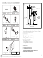
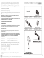
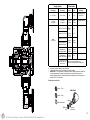
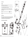
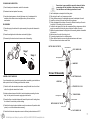
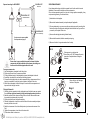
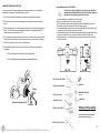
Guarantee & Registration
Guarantee
All products are manufactured to the highest standards and 5-year guarantee covers any defect in
manufacture.
Any part found to be defective during the above guarantee period will be replaced without charge
providing that the product has been installed in accordance with our instructions, used as intended and
maintained/serviced as recommended.
In the unlikely event that any problems are encountered with this product's performance on installation,
you must obtain guidance/authorisation from our Customer Service Department before any remedial
action is taken and be able to supply proof and date of purchase.
The guarantee excludes damage caused by accident, misuse or neglect and does not cover the
following:
-
Those components subject to wear and tear such as 'O' rings and washers etc,
Damage caused by faulty installation,
Damage caused by any waterborne debris,
Damage caused by improper cleaning products,
Damage caused by the use of non-Bristan parts,
The product being used for a purpose other than intended.
Fitting Instructions For Models :-
KN SHXAR C
- Colonial Surface Mounted Thermostatic
Shower Valve With Adjustable Riser Kit
KN SHXRR C
- Colonial Surface Mounted Thermostatic
Shower Valve With Rigid Riser Kit
The company reserves the right, in the event of a claim not covered by the guarantee, to charge the
claimant for parts and labour at current rates. This guarantee is given in addition to and does not affect your
statutory rights.
In the interests of continuous product development we reserve the right to alter the specification as
necessary.
Registration
SOQ SHUAR C - Sonique Universal Thermostatic
Shower Valve With Adjustable Riser Kit
To register your product with us please complete and return the enclosed registration card.
PRODUCT CODE: KN SHXAR C
KN SHXRR C
SOQ SHUAR C
TELEPHONE HELP LINE! 0844 701 6273
Bristan Group Ltd
Birch Coppice Business Park
Dordon
Tamworth
Staffordshire
B78 1SG
UK
Before starting any installation project please consider:
Prior to drilling into walls, check there are no hidden electrical
wires, cables or water supply pipes with the aid of an
electronic detector. If you use power tools do not forget:
- Wear eye protection
- Unplug equipment after use
A Masco Company
www.bristan.com
Web:
Tel:
0844 701 6274
Facsimile: 0844 701 6275
Email: [email protected]
(FI KN / SOQ MINI)
Please keep these instructions for future reference and the
request of replacement parts
800462/A
(REV.D1)
(AJ)
For latest prices and delivery to your door visit MyTub Ltd 0845 303 8383 www.mytub.co.uk
Notes
INTRODUCTION
Your Bristan single control mini shower fitting is a thermostatic mixer incorporating a wax
capsule thermostat to ensure constant showering temperatures.
This valve has been designed to comply with BS EN 1111:1999 and BS EN 1287:1999,
manufactured to the highest quality standards and is a 'Water Regulations Advisory Scheme'
approved product.
These instructions are for your guidance to a safe and successful installation and should be
left with the user.
The valve is supplied with the hot inlet on the left and the cold inlet on the right when
viewed from the front. The hot supply must be connected to the inlet port marked ‘H’.
Please read these instructions carefully, and ensure the shower valve is installed to
Local Water Authority regulations. If in doubt, contact a registered plumber or the
Secretary of Institute of Plumbing, address as follows Institute of Plumbing
64 Station Lane
Hornchurch
Essex
RM12 6NB
Tel: 01708 472791
SITE REQUIREMENTS
To ensure the correct operation of your shower mixing valve it is important to fully
understand your site installation. This thermostatic mixing valve will suit the following HIGH PRESSURE
LOW PRESSURE
MAINS PRESSURE
PUMPED PRESSURE
UNEQUAL PRESSURE
GRAVITY PRESSURE
The shower mixing valve may require slight adjustment depending on your site installation
the following may apply.
GRAVITY FED
Fig A shows a typical layout. The distance between the bottom of the cold water tank
and the shower head must be a minimum of 1 metre (0.1 bar).
The cold water supply for the valve must be connected directly to the cold water tank
and the hot water supply connected to a Essex or Sussex Flange in the side of the
cylinder or to the vent and draw off pipe of the hot water cylinder, as close to the top of the
cylinder as possible.
19
2
For latest prices and delivery to your door visit MyTub Ltd 0845 303 8383 www.mytub.co.uk
Available Shower Valve Spares For Models : SOQ SHUAR C
FIG A
COLD WATER
STORAGE TANK
SHOWER HEAD
O’ring Seals Kit
1m. (39”) min.
Cartridge Assembly
SK1200-1
QTY 1
SK971006
QTY 1
BATH OR
SHOWER
CUBICLE
MAINS
WATER SUPPLY
Thermostat & Piston Assembly
SK1500-3
QTY 1
Backplate Assembly
SK150024CP
QTY 1
HOT WATER TANK
The above installation is recommened for most showers, if however your cold supply is
mains pressure then the following will be required;
MAINS COLD SUPPLY
Sonique Knob Assembly
SK1200-4SQCP
QTY 1
Inlet Elbow Assembly (Pair)
SKINLET-11CP
QTY 2
A) *Hot supply between 1 to 4 metres (0.1-0.4 bar)
Mains cold supply up to 10 bar.
*Fit 7 litre (green) limiter into cold inlet elbow only.
B) *Hot supply above 5 metre (0.5 bar)
Mains cold supply up to 10 bar.
*Fit 5 litre (yellow) limiter into hot inlet elbow.
*Fit 7 litre (green) limiter into cold inlet elbow.
UNVENTED SYSTEM
Fit 5 litre (yellow) limiter into hot inlet elbow.
Fit 7 litre (green) limiter into cold inlet elbow.
This will give a shower outlet of about 10 litres/min. (2.2 gallons per min).
(Cold supply to shower from same source as hot).
Concealing Plate Kit
SK1200-5CP
QTY 1
3
18
For latest prices and delivery to your door visit MyTub Ltd 0845 303 8383 www.mytub.co.uk
INSTANTANEOUS GAS WATER HEATER & COMBINATION BOILER (UNVENTED)
The hot supply from the heater is to be connected to the hot inlet elbow and cold inlet
elbow connected to the cold supply. Fit 7 litre flow limiter (as supplied) into the cold inlet
elbow.
Available Shower Valve Spares For Models : KN SHXAR C
KN SHXRR C
INSTANTANEOUS (NON STORAGE)
7-9kw Electric Water Heaters (Unvented)
O’ring Seals Kit
This will require a 5 litre (yellow) flow limiter as supplied into cold inlet of the shower mixer
only.
IMPORTANT - It is a requirement of Instantaneous Electric Water Heaters that a
stable flow of water passes through the heater.
Cartridge Assembly
SK1200-1
QTY 1
SK971006
QTY 1
This requirement can be satisfied by using a flow stabilizer and should be adjusted to give
a temperature of between 45 & 50°C from the heater.
Flow Stabilizers should be fitted prior to the heater.
PUMPED SHOWERS
Your Thermostatic shower is also ideal for power shower installation and can be matched
to most makes of booster pump. For further information contact your local stockist.
Thermostat & Piston Assembly
WATER REGULATIONS
SK1500-3
QTY 1
Backplate Assembly
SK150024CP
QTY 1
When connecting a mixing valve to gravity hot supply and mains cold water, current
regulations will apply.
“Shower installation in all respects must meet with the requirement of Water Regulations”.
If in doubt you should contact your local Water Authority for advice or a registered member
of the Institute of Plumbers Tel: 0170 847 2791 for a list of your nearest plumbers.
SPECIFICATION
Inlet Connections:
15 mm compression, with 150mm between centres.
Water Pressures:
Min. 0.1 bar - Max. 5 bar - Max. Pressure ratio 5:1
Inlet Elbow Assembly (Pair)
SKINLET-10CP
(Maximum differential between the hot and cold pressures should not exceed 5:1 ratio)
Maximum Outlet Temp:
QTY 2
Factory set to 41°C (can be re-set to suit site conditions).
HOT AND COLD SUPPLY TEMPERATURE
Minimum recommended Hot:
Maximum Hot Supply:
Maxium Cold Supply:
60°C
80°C
25°C
Note: The inlet hot water temperature must be at least 10°C above the required blend
temperature.
Colonial Knob Assembly
SK1200-4KNCP
QTY 1
17
4
For latest prices and delivery to your door visit MyTub Ltd 0845 303 8383 www.mytub.co.uk
Supply System
Flow Limiter
Cold Supply
Hot Supply
Cold
Hot
Comments
0.1 to 1.0 bar
0.1 to 1.0 bar
No
No
Maximum pressure
loss ratio 5:1
1 to 5 bar
or Pumped
1 to 5 bar
or Pumped
Green
(7 litre)
Yellow
(5 litre)
Gravity 0.1 to 0.2 bar
White
Disc
No
Gravity 0.2 to 0.5 bar
Green
(7 litre)
No
Green
(7 litre)
Yellow
(5 litre)
Instantaneous
Gas Water Heater
Green
(7 litre)
*Yellow
(5 litre)
**Instantaneous
Electric Water Heater
Yellow
(5 litre)
No
Any Vented (open outlet)
heater gas/electric. Eg
electric shower
DO NOT USED WITH MIXER VALVETHIS WOULD BE EXTREMELY DANGEROUS
Mains
1.5 to 10 bar
Gravity above 0.5 bar
Unvented Mains/
Mains Pressurised
#
*
**
# Use arrangement
for pumped system
Limiters can be fitted if water economy is required.
Yellow (5 litre) limiter may not be necessary on some gas heaters.
IMPORTANT! - It is a requirement of Instantaneous Electric Water Heaters that a stable flow
of water passes through the heater. This requirement can be satisfied by using a flow
stabiliser (960060) fitted prior to the heater and should be adjusted to give a temperature of
between 45-50°C from the heater.
Fitting limiter or orifice disc
Green - 7 litre
Inlet elbow
Yellow - 5 litre
White orifice disc
Retaining
ring
Washer
Limiter or
orifice disc
5
16
For latest prices and delivery to your door visit MyTub Ltd 0845 303 8383 www.mytub.co.uk
GENERAL
1) Before commencing it is advisable to install isolating valves on both hot and cold
supplies for flushing out and servicing purpose.
Cartridge assembly
SOQ SHUAR C
INSTALLATION
Before mounting the valve to the wall, the position for the pipe work should be decided.
Three inlet positions - top, bottom and rear are possible simply by rotating the elbows in
the valve body. With the elbow screwed fully against the valve body it can be
unscrewed a maximum of 1.5 turns to allow for lateral tolerance.
Concealing plate assembly for
SOQ SHUAR C
PIPE POSITION
Thermostat & Piston assembly
5) In hard water areas the mixing valve may require more frequent cleaning and
servicing.
KN SHXAR C
KN SHXRR C
4) Please ensure filters are fitted correctly. Failure to do so WILL invalidate your
warranty.
Elbow assembly for
KN SHXAR C
KN SHXRR C
3) A simple way of flushing out the pipes is to fit the outlet adaptor to the pipe and
secure with the compression nut and olive, fit the hose to the adaptor and flush out
pipes to the waste.
Handle Fixing
2) It is important that both supply pipes are flushed before connecting mixing valves to
ensure no pipe/plumbing debris enters the mixing valve.
For shower valve spares available for this product see page 17
Elbow assembly for
SOQ SHUAR C
Exposed Mounting For KN SHXAR C
15
6
For latest prices and delivery to your door visit MyTub Ltd 0845 303 8383 www.mytub.co.uk
CLEANING AND LUBRICATION
Ensure there is space available to mount the shower kit before
commencing with the installation of the shower valve taking
Care that there are not hidden pipes/cables in the wall.
1) Soak all metal parts in descalent, wash off in clean water.
2) Examine all seals and replace if necessary.
3) Use silicon based grease on all seals (light smear only). A maintenance kit is
available, which contains all seals and grease from your local stockist or
manufacturer.
RE-ASSEMBLY
1) Place the spring in the bottom of the piston assembly, then place the thermostat in
the top.
2) Screw the cartridge back into the shower valve and fully tighten.
3) Re-assembly the valve head work in reverse order of dismantling.
1) Use the backplate as a template for the fixing holes.
2) Drill and plug the wall to suit, screws are provided.
3) Fit the grubscrew loosely to the backplate and secure the backplate to the wall.
4) Locate the valve body to the wall and lock with the grubscrew.
5) Fit the outlet adaptor to the bottom of the valve for flexible kits and top of the valve
for rigid kits. Fit the outlet plug in the unused outlet.
6) Connect the inlet pipes to the valve with compression fittings, please ensure the hot
supply is connected to the hot inlet port as marked on the base of the valve.
7) Measure the centres between the fixing holes of the mounting brackets. Assembled
to the riser kit.
8) Mark centres on the wall, drill and plug to suit.
9) Fix mounting brackets to wall in a vertical position.
10) Place slider rail brackets over mounting brackets and secure with screw.
11) Connect shower hose to shower valve outlet.
BKT SP 4220C 217 SB TD
Slider Rail Bracket
CAP 114220 30 CA
Stage 1
Stage 2
Mounting Bracket
Securing Srew
HAND102 C
Shower Kit Assembly
BKT 764220 04 CA
GENERAL FAULT DIAGNOSIS
If your thermostatic mixing valve fails to operate either immediately upon installation or
after a period of time, the following points should be checked;
HOSE104 C
RTNR 745112 01 CA
1) Check the hot & cold water feeds have been correctly fitted with hot on the left and
cold on the right when viewed from the front.
2) Isolate supplies and ensure that both hot and cold supplies are reaching the valve
body. You may need to dis-connect supply pipes to ensure this.
760680CP-RAIL
Mounting Bracket
3) Ensure that there is no debris between the faces of the piston and it’s mating faces,
the bottom of the valve body and the cartridge.
Slider Rail Bracket
BKT SP 4220C 217 SB TD
4) Check that the valve has been installed correctly in accordance of its particular feed
system (i.e use of flow limiters where necessary).
5) Check that the hot water temperature source is sufficient; preferred minimum of 60°C.
Securing Srew
CAP 114220 30 CA
7
14
For latest prices and delivery to your door visit MyTub Ltd 0845 303 8383 www.mytub.co.uk
SKJERA-2CP
Exposed mounting for KN SHXRR C
SERVICE/MAINTENANCE
Shower Arm
If your thermostatic mixing valve fails to operate it could be the result of incorrect
installation. Please refer to installation and site requirements.
If the valve has operated correctly for a time, but no longer performs acceptably, it may
require servicing/cleaning. Proceed as follows;
SKJERA-1CP
Showerhead & Swivel
1) Isolate hot and cold supplies.
2) Remove the headwork assembly and spline adaptor if applicable.
SKJERA-3CP
Riser Tube Assembly
For shower valve spares available
For this product see page 17
3) For concealed models, you can remove the concealing surround by inserting a thin
blade at the back of the plate and rotating the blade round the back, you can then
proceed to pull the plate off the valve.
4) Unscrew the cartridge (standard right hand thread).
5) Remove the thermostat, distributor assembly and spring.
6) Remove all visible ‘o’ rings and washers from the body.
FIG E
30mm spanner / socket required.
Ensure that you DO NOT damaged the valve,
pipe work or backplate when undoing the
headwork.
Ensure there is space available to mount the shower kit before
commencing with the installation of the shower valve taking care
that there are not hidden pipes/cables in the wall.
Fitting the Shower valve
1) Use the backplate as a template for the fixing holes.
2) Drill and plug the wall to suit, screws are provided.
3) Fit the grubscrew loosely to the backplate and secure the backplate to the wall.
4) Locate the valve body to the wall and lock with the grubscrew.
5) Connect the inlet pipes to the valve with compression fittings, please ensure the hot
supply is connected to the hot inlet port as marked on the base of the valve.
6) Ensure the outlet adaptor is fitted to the top of the valve with the compression end
exposed to take the rigid riser tube.
Fitting the Shower kit
1) Slide the rigid riser assembly into the outlet adaptor and hold the shower arm against
the wall.Ensure rigid riser assembly is fully pushed together where joints occur
2) Mark the positions of the shower arm fixing holes on the wall. Remove the shower
arm assembly and place safely to one side.
3) Drill and plug wall as per hole position marking.
4) Slide the compression nut and olive onto the bottom of the riser assembly and place
assembly into the valve oultet.
5) Match the shower arm to the holes drilled previously and secure shower arm to the
Wall.
6) Tighten the compression nut and olive to the valve outlet.
7) Fit the shower head to shower arm.
Ensure that you don’t damage
the faces of the piston.
Stage 2
Return Spring
Stage 1
Piston Assembly
Thermostat
Cartridge
13
8
For latest prices and delivery to your door visit MyTub Ltd 0845 303 8383 www.mytub.co.uk
MAXIMUM TEMPERATURE SETTING
Exposed Mounting For SOQ SHUAR C
Ensure there is space available to mount the shower kit before
commencing with the installation of the shower valve taking care
that there are not hidden pipes/cables in the wall.
The maximum mixed water temperature should be limited to ensure no undesirable
temperature is obtained. If necessary adjust as follows 1) Turn the lever/knob anti-clockwise to the maximum flow/temperature position.
2) Remove the control knob using a hexagonal key to expose temperature adjusting
screw.
3) Using a hexagonal key, turn the temperature adjusting screw to alter the temperature.
(Note :- This will be the maximum temperature setting. It is recommended that the
Temperature be set no higher than 43°C)
4) Once correct temperature is achieved, use the knob to close the valve and replace the
control knob. Ensure the stop on the control knob is in the correct position (vertically
down) thus allowing the valve to turn on anti-clockwise.
1) Use the backplate as a template for the fixing holes.
2) Drill and plug the wall to suit, screws are provided.
3) Fit the grubscrew loosely to the backplate and secure the backplate to the wall.
4) Locate the valve body to the wall and lock with the grubscrew.
5) Fit the outlet adaptor to the bottom of the valve for flexible kits and top of the valve
for rigid kits. Fit the outlet plug in the unused outlet.
6) Connect the inlet pipes to the valve with compression fittings, please ensure the hot
supply is connected to the Hot inlet port as marked on the base of the valve.
7) Mount shower kit in a suitable position and connect the flexible hose fo the outlet
of the shower valve
5) Securely tighten the grubscrew to lock the handle in place and re-fit lever where
applicable.
>
Turn the adjusting screw clockwise for cooler temperature.
>
Turn the adjusting screw anti-clockwise for warmer temperature.
BKT SP 4140C 217 SB Td2
RAIL 324140 L25*580BCA
HAND100 C
BKT 764140 04 2CA
WSHR MA076RJ000O
(2 off)
RTNR 745190 01 CA
HOSE104 C
Cooler
Temperature Adjusting Screw
Warmer
DISH SP 4140 217 SB TD
Shower Kit Assembly
For shower valve spares available
for this product see page 18
BKT SP 4140C 217 SB Td3
9
12
For latest prices and delivery to your door visit MyTub Ltd 0845 303 8383 www.mytub.co.uk
Concealed Mounting For SOQ SHUAR C Shower valve
For shower valve spares available
for this product see page 18
Ensure there is space available to mount the shower kit before
commencing with the installation of the shower valve taking
Care that there are not hidden pipes/cables in the wall.
Outlet Plug
Cold Supply Inlet
It is essential that when installing a concealed mixing valve, full access to the valve can be
achieved for servicing purposes. Isolating valves are recommended for ease of isolating the
supplies when servicing is required.
Hot Supply Inlet
Rear access to the mixing valve is always preferred wherever possible (e.g... an airing cupboard
or panelled walls), as this removes the need to disturb any tiling or decorating features at the front
of the valve.
Concealing Plate
Valve outlet
IMPORTANT : Please note the depth of cavity required to mount the concealed valve.
From the back face of the valve to front face of the tiling should be between 68 - 77mm
to ensure correct fixing of the concealing plate.
Plastic cap
1) Cut an aperture in the cavity for the shower valve no larger than 190mm wide and
145mm High.
2) Fit the outlet adaptor to the bottom of the valve. Ensure correct orientation for flat face
connection. Fit the outlet plug in the unused outlet.
3) Rotate the supply inlet elbows to the desired position (Top, Bottom, Rear Supply).
4) Ensure the valve control knob is in the off position (Lever down position).
5) Use the backplate of the shower valve as a template for the fixing holes to secure
the valve in the cavity. Drill and plug the wall to suit, screws are provided and secure
the backplate to the wall.
Grubscrew
From valve
outlet
Wall outlet elbow
NOTE :ENSURE VALVE IS MOUNTED IN THE CENTRE OF THE APERTURE TO
ENSURE THE CONCEALING PLATE FULLY COVERS THE APERTURE OPENING.
6) With the hot inlet port on the left & cold Inlet port on the right (As indicated on the
base of the valve), locate the valve body to the wall and secure with grubscrew in
the backplate.
7) Connect the inlet pipes to the valve with compression fittings, please ensure
the hot supply is connected to the hot inlet port.
8) Secure wall outlet elbow to wall and connect shower valve outlet in cavity.
9) Connect the hose to the wall outlet elbow, turn on the water and test the valve installation for
any leaks.
10) Ensuring there are no leaks, turn off the shower valve (The control knob should be in the
downward position), Remove the plastic cap on the control knob, loosen the grubscrew and
remove the control knob.
11) To fit the concealing plate run a bead of silicon sealant around the groove on the rear outer
seal. Use a smear of washing up liquid around the inner seal (This will aid Installation when
placing the plate onto valve). Slide the concealing plate onto the valve body and press firmly
against the tiling around the edges. Remove any excess sealant from around the edges.
12) Re-fit the control knob with the knob in the downward position, tighten the grubscrew with a
hexagonal key to secure the knob and refit the plastic cap.
For ease of installation
Smear a small amount
of washing up liquid
around this inner seal
Control Knob
off position
To Shower Hose
Tile Face
Rear outer seal
If fitted correctly the valve should turn on anti-clockwise from the 6 o’clock off position to the 9
o’clock maximum on position.
11
10
For latest prices and delivery to your door visit MyTub Ltd 0845 303 8383 www.mytub.co.uk