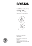
1
Installation Instructions
and User Guide
Capri & Sonique
Thermostatic Surface
Mounted/Recessed Mini
Shower Valves
C
H
Models covered: CAP2 SHUAR C
& SOQ2 SHUAR C
Please note: The Capri Shower Valve is
shown as a typical example.
Please keep this booklet for future
reference.
Installer, when you have read these
instructions please ensure you leave them
with the user.
Contents
Thank you for choosing Bristan, the UK’s leading showers and taps expert.
Your Bristan shower valve is a thermostatic mixer incorporating a wax capsule
thermostat to ensure constant shower temperatures. These instructions are for your
guidance to a safe and successful installation and should be left with the user.
All products manufactured and supplied by Bristan are safe providing they are installed
correctly and receive regular maintenance in accordance with these instructions.
Important Safety Information................................................ 3
General Information.................................................................. 4
Product Features....................................................................... 5
Installation Requirements..................................................... 6-11
Flow Regulators.................................................................... 9-10
Dimensions................................................................................ 12
Specifications............................................................................ 13
Pack Contents....................................................................... 14-15
CAP2 SHUAR C..................................................................... 14
SOQ2 SHUAR C..................................................................... 15
Installation............................................................................ 16-23
Surface Mounted Shower Valve - First Fix........................ 16
Surface Mounted Shower Valve - Second Fix...................... 17
Recessed Shower Valve - First Fix.................................... 18-19
Recessed Shower Valve - Second Fix.................................. 20
Riser Rail.............................................................................. 21-23
Operation............................................................................... 24
Commissioning.......................................................................... 25
Maintenance.............................................................................. 26-28
Map of Hard Water Regions in the UK................................. 28
Troubleshooting......................................................................... 29-30
Guarantee.................................................................................. 31-32
Service Policy............................................................................. 32
2
Important Safety Information
• Please read these instructions thoroughly and retain for future use.
• All products manufactured and supplied by Bristan are safe provided they are installed,
used correctly and receive regular maintenance in accordance with these instructions.
• If you are in any doubt about your ability to install this shower valve safely you must
employ the services of an experienced qualified plumber.
• These fittings need to be installed in accordance with, and meet the requirements of
the Water Supply (Water Fittings) Regulations 1999 and Scottish Byelaws 2004.
•
Warning: Do not operate the shower valve if you suspect it is frozen. Do not site
the shower valve where it might be subjected to freezing conditions.
• Do not crush or kink the shower hose, this could damage the hose and cause leaks.
• Remove all packaging and check the contents for damage before starting installation.
• Before starting any installation please consider the following: before drilling into walls,
check that there are no hidden electrical wires, cables or water supply pipes. This can
be checked with the aid of an electronic detector.
• If power tools are used do not forget to:
- Wear eye protection
- Unplug equipment after use
• Fitting isolating valves to the inlet feeds is required for ease of maintenance.
•
Warning: Before installing the new shower valve it is essential that you thoroughly
flush through the pipework in order to remove any remaining swarf, solder, etc.
Failure to carry out this procedure could cause problems or damage to the workings of
the shower valve.
• It is recommended that when installing the valve in a recessed situation, full access
is provided for servicing purposes.
• This shower valve must not be modified in any way as this will invalidate the
guarantee.
3
General Information
Operating pressure range: Minimum 0.1 bar, Maximum 5.0 bar.
Maximum static pressure: 10.0 bar.
This product has been tested to the TMV2 scheme which complies with the BS EN
1287:1999 (LP) and BS 1111:1999 (HP) thermostatic mixing valve standards and satisfies
the requirements of the water supply (water fittings) regulations 1999 and current
bylaws.
BS 6700 recommends the temperature of stored water should never exceed 65°C.
A stored water temperature of 60°C is considered sufficient to meet all normal
requirements and will minimise the build up of lime scale in hard water areas (see
Map of Hard Water Regions in the UK on page 28).
If the fitting is installed at low pressure (tank fed), then the minimum distance from the
highest installed position of the showerhead to the underside of the cold tank should be
at least 1 metre to ensure adequate performance.
Note: Nominally equal (balanced) inlet supply pressures are recommended for optimum
performance with mixer showers.
These shower valves should be installed in compliance with the Water Regulations.
If in doubt, contact a registered plumber or your Local Water Authority or the Secretary
of The Institute of Plumbing, address as follows;The Institute of Plumbing,
64 Station Lane,
Hornchurch,
Essex, RM12 6NB
Tel: 01708 472791
4
Product features
1. On/Off and Temperature Control
Capri Shower Valve (Surface Mounted)
Turn lever anti-clockwise to turn on and
increase temperature.
C
H
Turn lever clockwise to turn off and
decrease temperature.
2. Shower Hose (Surface mounted option)
Connects the showerhead to the shower
valve (recessed option attaches to wall
outlet).
C
H
1
2
Sonique Shower Valve (Surface Mounted)
1
2
Recommended Usage
Domestic
Heavy
Commercial
Light
Commercial
Health Care
5
Installation Requirements
This shower valve must be installed
in compliance with current water
regulations. If you have any doubts about
the water regulation requirements contact
your local water services provider or use
the services of a professional plumber.
Important: If you install this shower
valve with a gravity fed system, there must
be a minimum head (vertical distance)
from the underside of the cold water
storage tank to the showerhead position
of at least 1 metre.
This shower valve is suitable for use with
the following water supply systems:
Note: Pumped system (with Essex
flange) If you install this shower valve to
a pumped gravity fed system where the
minimum head (vertical distance) from
the underside of the cold water storage
tank to the top of the hot water cylinder
is less than 1 metre we recommend an
Essex flange is used as shown.
• Gravity Fed Hot and Cold
(pressure balanced)
• Gravity Fed Hot and Mains Cold
(differential pressure - see Specification
section on page 13)
• Instantaneous water heater
(combination boiler)
Flushing Pipe-work
• Pumped System
Important: Before connecting the
shower valve (see ‘Installation’ on pages
16-23), supply pipe-work must be flushed
to clear debris before connecting the
shower valve. Debris will reduce the
performance and life of the shower.
Gravity Fed Hot and Cold
Gravity Fed Hot and Mains Cold
• Unvented System
1m min.
1m
min.
cold mains supply
6
cold mains supply
Installation Requirements
Instantaneous Water Heater
Unvented System
cold mains supply
Pumped System
cold mains supply
Pumped System (with Essex flange)
1m min.
1m min.
If less
than 1m
see note.
50mm
cold mains supply
Key:
Isolating
Valve
cold mains supply
Reducing
Valve
Shower
Valve
Pump
Essex
Flange
7
Installation Requirements
Conditions of use for Type 2 (Thermostatic mixer) valves
High Pressure
Low Pressure
10
10
Maximum Static Pressure (Bar)
Flow Pressure, Hot & Cold (Bar)
0.5 to 5
0.1 to 1
Hot Supply Temperature (˚C)
55 to 65
55 to 65
Cold Supply Temperature (˚C)
Equal to or Less than 25
Equal to or Less than 25
Note: Valves operating outside these
conditions cannot be guaranteed by the
Scheme to operate as Type 2 valves.
If a water supply is fed by gravity then
the supply pressure should be verified
to ensure the conditions of use are
appropriate for the valve.
Recommended outlet
temperatures
The BuildCert TMV scheme recommends
the following set maximum mixed
water outlet temperatures for use in all
premises:
44˚C for bath fill but see notes below;
41˚C for showers;
41˚C for washbasins;
38˚C for bidets.
The mixed water temperatures must
never exceed 46˚C.
The maximum mixed water temperature
can be 2˚C above the recommended
maximum set outlet temperatures.
8
Note: 46˚C is the maximum mixed water
temperature from the bath tap. The
maximum temperature takes account of
the allowable temperature tolerances
inherent in thermostatic mixing valves and
temperature losses in metal baths.
Warning: It is not a safe bathing
temperature for adults or children.
The British Burns Association
recommends 37 to 37.5˚C as a
comfortable bathing temperature for
children. In premises covered by the Care
Standards Act 2000, the maximum mixed
water outlet temperature is 43˚C.
The thermostatic mixing valve (TMV)
will be installed in such a position that
maintenance of the TMV and its valves and
the commissioning and testing of the TMV
can be undertaken.
The fitting of isolation valves is required
as close as is practical to the water supply
inlets of the thermostatic mixing valve.
Installation Requirements
Selecting Flow Regulators
Supply System
Flow Regulator
Cold Supply
Hot Supply
Cold
Hot
Comments
0.1 to 1.0 bar
0.1 to 1.0 bar
No
No
Maximum pressure
loss ratio 5:1
1 to 5 bar
or pumped
1 to 5 bar or pumped
Green
(7 litre)
Yellow
(5 litre)
◊ Use arrangement
for pumped system
Gravity
0.1 to 0.2 bar
White Disc
No
Gravity
0.2 to 0.5 bar
Green
(7 litre)
No
Green
(7 litre)
Yellow
(5 litre)
Instantaneous Water
Gas Heater
Green
(7 litre)
* Yellow
(5 litre)
** Instantaneous Water
Electric Heater
Yellow
(5 litre)
No
Mains
1.5 to 10 bar
Gravity
above 0.5 bar
Unvented Mains /
Mains Pressurised
Any Vented (open outlet)
Heater Gas / Electric.
Eg electric shower
Do not use with a mixer valve this would be extremely dangerous
◊ Regulators can be fitted if water economy is required.
*
Yellow (5 litre) regulator may not be necessary on some gas water heaters.
**
Important: It is a requirement of Instantaneous Electric Heaters that a stable
flow of water passes through the heater. This requirement can be satisfied by
using a ‘flow stabiliser’ fitted prior to the heater and should be adjusted to give a
temperature of between 45 - 50˚C from the heater.
9
Installation Requirements
Flow Regulators etc.
Flow regulators are factory fitted.
Study the table on the previous page and
decide which flow regulators etc. are
required for your particular situation.
4
Compression
nut
Unscrew both inlet elbows from the valve
body and both compression nuts from the
elbows.
Insert filters (4), washers (5), required
flow regulators / white disc (7, 8 or 9) and
retaining rings (6).
Reattach the compression nuts (ensuring
the olives are in place) and screw the inlet
elbows back into the valve body.
10
Inlet
elbow
5
7, 8 or 9
6
Installation Requirements
This fitting needs to be installed in
accordance with the following Installation
Requirements and Notes (IRN) to ensure
they meet the requirements of the Water
Supply (Water Fittings) Regulations 1999
and the Scottish Byelaws 2004.
IRN R001: See text of entry for Installation
Requirements or Notes.
IRN R040 - Schedule 2-15 (1): The
fitting shall be installed so that its outlet
discharges above the spill-over level of
any fixed appliance as indicated below:-
Size of tap or
combination fitting
Vertical distance
of outlet above
spill-over level
1. Not exceeding ½” 20mm
2. Exceeding ½”
but not
exceeding ¾”
25mm
3. Exceeding ¾”
70mm
For backflow protection in domestic or
installations up to, and including, Fluid
Category 3.
If the fitting cannot be installed as
indicated in the table opposite it shall be
installed as either a or b below:
a: with an approved double check valve
assembly or some other no less effective
backflow prevention device immediately
upstream of the inlet.
b: so that it draws water by gravity only
from a cistern, or cylinder having a
permanently open vent pipe, and the
distributing pipe supplies no other fittings
(other than a draining tap) at a lower level.
For backflow protection in premises or
installations up to, and including Fluid
Category 5.
The vertical distance of the outlet above
the spill-over level shall be not less
than 20mm or twice the diameter of the
inlet pipe to the fitting, which ever is the
greater. If the fitting cannot be installed
as indicated it shall be installed with a
backflow prevention arrangement suitable
for the Fluid Category.
11
117
74
Dimensions (mm’s)
Surface Mounted Shower Valve
74
117
660
148 - 152
C
H
92
C
660
660
H
*
Recessed Shower Valve
148 - 152
165
C
H
C
*Note: The Riser rail wall brackets can be
positioned up or down the riser rail (max.
600mm apart) as required. This allows any
existing holes to be reused or covered by
the wall brackets. The brackets can also
be adjusted to sit in the middle of the tiles
or in the tile joints.
210
68 - 77
C
H
C
12
H
H
Specifications
Specifications
Inlet connections: 15mm compression, with approximately 150mm between centres.
Operating pressure range: Min. 0.1 bar - Max. 5.0 bar - Maximum recommended
imbalance between hot and cold supply should not exceed a ratio of 5:1.
Maximum outlet temp: Factory pre-set to 41°C (can be re-set to suit site conditions).
Supply requirements:
Minimum cold water supply temperature: 5°C.
Maximum cold water supply temperature: 25°C.
Maximum hot water supply temperature: 80°C.
(a maximum hot water supply temperature of 60 - 65°C is recommended for
ablutionary purposes)
Note: The inlet hot water temperature must be at least 10°C above the required blend
temperature (eg. shower temperature 43°C: minimum hot supply 53°C).
Minimum dynamic pressure: 0.1 bar.
Maximum dynamic pressure: 5.0 bar.
Maximum static pressure: 10.0 bar.
13
Pack Contents - CAP2 SHUAR C
1 Shower valve
1
2 Concealing plate
C
3 Covers x2
H
4 Filters x2
2
5 Washers x2
6 Retaining rings x2
7 White disc
8 Green flow regulator
9 Yellow flow regulator
10 Hexagonal key
11 Showerhead (single function)
3
12 Wall outlet / Backnut
13 Rubber washers x2
14 Shower hose
4
15 Riser rail
5
16 Riser rail fixings x4/4
6
15
8
7
9
16
10
12
11
13
14
14
17
17 Backplate fixings x2/2
Pack Contents - SOQ2 SHUAR C
1 Shower valve
1
2 Concealing plate
3 Covers x2
4 Filters x2
2
5 Washers x2
6 Retaining rings x2
7 White disc
8 Green flow regulator
9 Yellow flow regulator
10 Hexagonal key
11 Showerhead (single function)
3
12 Wall outlet / Backnut
13 Rubber washers x2
14 Shower hose
4
15 Riser rail
5
16 Riser rail fixings x4/4
6
15
8
17 Backplate fixings x2/2
7
9
16
10
12
11
13
17
14
15
Surface Installation - First Fix
Surface Mounted Shower Valve
Before Installation
Flush through the pipework to ensure
removal of debris. Turn off the mains
water supply and close any isolating
valves.
Important: Water supplies to the mixer
must be with hot on the left and cold on
the right when viewed from the front.
148 - 152mm
1. Inlet positions
The shower valve has three inlet positions
- top, bottom and rear. Rotate the inlet
elbows as required.
With the elbows screwed fully against
the valve body it can be unscrewed a
maximum of 1.5 turns to allow for lateral
tolerance.
Hot
Cold
43.5mm
Backplate
fixing holes
Sufficient 15mm diameter supply pipes
should protrude through the finished
wall surface to fit fully into shower valve
elbows.
2. Attach backplate to wall
Loosen the ‘backplate’ grub screw on the
back of the valve using the hexagonal key.
Use the backplate as a template and mark
the centres of the fixing holes onto the
wall.
Warning: Please check for any hidden
pipes and cables before drilling holes in
the wall.
Drill suitable holes and insert the wall
plugs. Securely attach the backplate to
the wall using countersunk screws (17).
Note: If required, any decorating should
be complete now before starting the
Second Fix (page 17).
16
17
Backplate
Surface Installation - Second Fix
1. Attach shower valve
Place the covers (3) over the water supply
pipes. Insert the 15mm hot and cold water
supply pipes into the inlet connections and
tighten the nuts. Ensure the olives and
filters are in place.
Re-attach the shower valve to the
backplate by tightening the grub screw.
Hot
supply
Cold
supply
3
3
C
H
Note: The shower valve inlet positions are
shown at the rear as an example.
See pages 21-23 for installation of riser
rail and shower hose.
17
Recessed Installation - First Fix
Recessed Shower Valve
Before Installation
Important: Water supplies to the mixer
must be with hot on the left and cold on
the right when viewed from the front.
Flush through the pipework to ensure
removal of debris. Turn off the mains water
supply and close any isolating valves.
148 - 152mm
1. Inlet positions
The shower valve has three inlet positions
- top, bottom and rear. Rotate the inlet
elbows as required.
With the elbows screwed fully against
the valve body it can be unscrewed a
maximum of 1.5 turns to allow for lateral
tolerance.
Hot
Cold
43.5mm
Sufficient 15mm diameter supply pipes
should protrude through the finished
wall surface to fit fully into shower valve
elbows.
Backplate
fixing holes
2. Attach backplate to wall
Loosen the ‘backplate’ grub screw on the
back of the valve using the hexagonal key.
17
Use the backplate as a template and mark
the centres of the fixing holes onto the
wall.
Backplate
Hot
supply
Warning: Please check for any hidden
pipes and cables before drilling holes in
the wall.
Cold
supply
Drill suitable holes and insert the wall
plugs. Securely attach the backplate to
the wall using countersunk screws (17).
3. Attach shower valve
Insert the 15mm hot and cold water
supply pipes into the inlet connections
and tighten the nuts. Ensure the olives
and filters are in place.
Re-attach the shower valve to the
backplate by tightening the grub screw.
18
C
H
Note: The shower valve
inlet positions are shown at
the rear as an example.
Recessed Installation - First Fix
3. Fit wall outlet
There are two methods of fixing the wall
outlet depending on the type of wall:
a: With rear access once wall finished
Remove the backnut from the wall outlet
(12). Insert the wall outlet through a 2124mm hole in the wall and secure with the
backnut.
Backnut
12
Plumb in the wall outlet assembly to the
shower valve outlet.
b: Without rear access once wall finished
Fit a ‘wall plate elbow’ (not supplied)
within the wall cavity and plumb in from
the shower valve.
Once the wall has been finished, remove
the backnut from the wall outlet (12).
Note: The backnut is not required.
Screw the wall outlet into the ‘wall-plate
elbow’ using a suitable thread sealant.
Note: If required, any decorating should
be complete now before starting the
Second Fix (page 20).
Important note: Please note the depth of
the cavity required to mount the recessed
shower valve. From the back face of the
valve to the front face of the tiling should
be between 68-77mm to ensure correct
fixing of the concealing plate.
Take care to protect the shower valve
whilst finishing the surround.
19
Recessed Installation - Second Fix
1. Fit concealing plate
Note: The concealing plate (2) can be
used as a template by drawing around the
plate and measuring in by 15mm to give
sufficient clearance.
Run a bead of silicon sealant around
the groove on the rear outer seal. Use a
smear of washing up liquid around the
inner seal (this will help when fitting over
the valve lever).
C
Slide the concealing plate over the valve
lever and press firmly against the tiling
around the edges.
C
2
Note: If required the valve lever can be
removed from the valve before fitting
the concealing plate. Remove the plastic
cap, loosen the grub screw using the
hexagonal key (10) and carefully pull the
lever off. Once the concealing plate is
fitted, re-fit the valve lever.
C
20
H
H
H
Installation - Riser Rail
1. Mark the position
Position the assembled riser rail on the
wall, bearing in mind the different heights
of people likely to use the shower and the
length of the hose when connected to the
wall outlet.
Note: If replacing an existing riser rail,
check to see if the existing holes can
be reused or covered by the new wall
brackets. Try to avoid drilling close to the
edge of tiles, drill in the middle of the tiles
or in the tile joints.
With the riser rail vertical, mark the wall
bracket positions onto the wall.
Wall bracket
Release the slider handle and remove the
slider and wall brackets from the rail.
2. Attach wall brackets
Remove the end caps and clamps from
the wall brackets.
Slider
handle
Position the wall brackets in the marked
positions against the wall, ensure they
are vertically in line with each other and
mark the centres of the fixing holes onto
the wall.
Warning: Please check for any hidden
pipes and cables before drilling holes in
the wall.
Drill suitable holes and insert the wall
plugs. Securely attach the wall brackets to
the wall using the screws (16).
Tips: A piece of insulation or masking
tape positioned where holes are to
be drilled and before marking out the
exact position for the fixing holes will
help stop the drill bit from wandering,
particularly on a tiled surface.
Wall bracket
When working near a basin, bath or
shower insert plug or cover waste to
prevent losing small parts.
Take care not to drop tools/equipment
into basin, bath or shower during
shower installation.
16
Wall bracket
21
Installation - Riser Rail cont.
3.Insert rail clamps
Insert the rail clamps into both wall
brackets.
4. Insert riser rail
Push the riser rail up through the bottom
wall bracket.
Push the slider down onto the riser,
ensuring it is the correct way up - as
shown.
Then push the riser rail up through the
top wall bracket.
Rail clamp
Bottom wall
bracket
5. Tighten rail clamps
Centre the riser rail within the wall
brackets and tighten both clamps onto the
rail.
6. Fit wall bracket end caps
Push-fit the wall bracket end caps onto
both wall brackets.
End cap
22
Installation - Riser Rail cont.
Attaching the Shower hose
7. Connect shower hose to shower valve /
wall outlet
Screw the shower hose (ribbed nut
end) onto the shower valve / wall outlet
ensuring that the rubber washer is fitted.
C
H
8. Connect shower hose to showerhead
Screw the shower hose (conical end) onto
the showerhead ensuring that the rubber
washer is fitted.
Place the showerhead into the slider.
23
Operation
Hot
On/Off and Temperature Control
Turn the lever anti-clockwise to turn on
and increase temperature.
Turn the lever clockwise to decrease
temperature and turn off.
Riser rail
C
H
Turning the slider handle will allow the
slider to be raised and lowered and the
angle of the showerhead to be adjusted.
Off
Cold
Slider
handle
24
Commissioning
Commissioning notes for
Thermostatic Mixing Valves
The first step in commissioning a
thermostatic mixing valve is to check the
following:
1. The designation of the thermostatic
mixing valve matches the application.
2. The supply pressures are within the
valves operating range.
3. The supply temperatures are within the
valves operating range.
4. Isolating valves (and strainers
preferred) are provided.
If all these conditions are met, proceed to
set the temperature as stipulated in the
Maintenance section.
The mixed water temperature at the
terminal fitting must never exceed 46˚C.
It is a requirement that all TMV2 approved
valves shall be verified against the original
set temperature results once a year.
When commissioning / testing is due the
following performance checks shall be
carried out:
• Measure the mixed water temperature
at the outlet.
If there is no significant change to the set
outlet temperature (+/-2˚C or less change
from the original settings) and the failsafe shut off is functioning, then the valve
is working correctly and no further service
work is required.
Notes: If there is a residual flow during
the commissioning or the annual
verification (cold water supply isolation
test), then this is acceptable providing the
temperature of the water seeping from
the valve is no more than 2˚C above the
designated maximum mixed water outlet
temperature setting of the valve.
Temperature readings should be taken at
the normal flow rate after allowing for the
system to stabilise.
The sensing part of the thermometer
probe must be fully submerged in the
water that is to be tested.
Any TMV that has been adjusted or
serviced must be re-commissioned
and re-tested in accordance with the
instructions in the Maintenance section.
The installation of thermostatic mixing
valves must comply with the requirements
of the Water Supply (Water Fittings)
Regulations 1999.
• Carry out the cold water supply isolation
test by isolating the cold water supply to
the TMV, wait for five seconds, if water is
still flowing check that the temperature
is below 46˚C.
25
Maintenance
General Cleaning
Cartridge Maintenance
Your fitting has a high quality finish and
should be treated with care to preserve
the visible surfaces. All surfaces will
wear if not cleaned correctly, the only safe
way to clean your mixer is to wipe with a
soft damp cloth. Stains can be removed
using washing up liquid. All bath cleaning
powders and liquids will damage the
surface of your fitting, even the nonscratch cleaners.
We advise that the shower valve is
regularly serviced in hard water areas to
maintain the flow of water (see Map of
Hard Water Regions in the UK on page 28).
Note: Never use abrasive detergents or
disinfectants or those containing alcohol,
hydrochloric acid or phosphoric acid.
Bristan recommend E-cloth for
cleaning all of our bathroom
& kitchen products. Using
just water, E-cloth gives a
smear free, deep clean by breaking up
and holding dirt, which normal cloths
leave behind. Order through your Bristan
stockist (order code: ECLOTH).
Cleaning the Showerhead
Your Bristan showerhead has rub-clean
nozzles for easy cleaning. Simply rub
your fingers across the rubber spray jets
regularly and before you turn the shower
on to remove any scale or debris.
The hardness of the water in your area
will determine how often you should clean
your showerhead. Build up of scale in
particularly hard water areas combined
with constant use means you may need
to clean your showerhead once a week.
To ensure continued performance of
your shower the showerhead needs to be
regularly descaled.
26
Isolate both hot and cold water supplies to
the shower valve by either:
• Turning the water supply off at the
mains stopcock or
• Turning off the isolation valves to the
shower valve
1. Remove the lever: remove the plastic
cap, loosen the grub screw using the
hexagonal key (10) and carefully pull the
lever off.
2. Unscrew the cartridge anti-clockwise
(using a 30mm spanner) and remove from
the valve body.
3. Carefully remove the cartridge
assembly and spring. Remove all visible
‘O’ rings and washers from the body.
4. Place the cartridge in a bowl and
carefully add hot water (just off the boil)
and vinegar to de-scale the cartridge.
Leave in the solution until the water has
cooled and rinse with clean water.
5. Replace all seals and grease with a
silicon grease supplied by Bristan (part
number: SP-495-0002) and carefully refit.
6. Reset the maximum temperature and
refit the handle and cover.
Maintenance - cont.
Adjusting the Temperature
The shower valve has been factory set
with equal (balanced) hot and cold water
supply pressures with the hot water
supply at 65˚C.
If your operating conditions are different
from those above, the outlet water
temperature may differ from the factory
setting.
If required the shower valve can be recalibrated to suit your own temperature
requirements.
Set the temperature control lever to
maximum and check the temperature
of the water with a thermometer. If the
temperature is not correct, re-calibrate
the shower valve:
1. Turn the lever anti-clockwise to the
maximum temperature position.
2. Remove the lever: remove the plastic
C
cap, loosen the grub screw using the
hexagonal key (10) and carefully pull the
lever off.
3. Using the hexagonal key, turn the
temperature adjusting screw to alter the
temperature.
• Turn clockwise for a cooler temperature
• Turn anti-clockwise for a warmer
temperature
Note: This will be the maximum
temperature setting, it is recommended
that the temperature is set no higher than
43˚C.
4. Once the correct temperature is
achieved, re-attach the lever and close
the valve. Ensure the stop on the lever is
in the correct position (vertically down),
allowing the valve to turn on anticlockwise.
5. Tighten the grub screw to lock the lever
in place and push fit the plastic cap.
H
Temperature
adjusting screw
Cooler
Warmer
27
Hard Water Regions in the UK
Soft to
moderately soft
0 - 100mg/l as
calcium carbonate
equivalent
Hard to very hard
Above 200mg/l as
NE
calcium carbonate
SR
equivalent
DH
NE
SR
DH
CA
CA
DL
TS
NE DL
LA
LA
Slightly hard to
moderately hard
100 - 200mg/l as
calcium carbonate
equivalent
BD
FY
L
LL
CH
LL
SY
LD
SA
NP
CF
TA
EX
PL
TR
BB
PR
YO
HG
BD
CA
FY HU PR
LS
BB
DH
HG
DL
TS
SR
YO
TS
LS
HU
HX
HX
WF
LA
WF
BL OL HD
BL OL HD
DN
YODN
WN
HG
WN
L
MBD
M
S
WA
S
WA
LN
SK
LN
SK LL
HU
BB
LS
CHPR CW
FY
CW
HG
HX
HG
WF
LL
BL OL HDDE
DN
ST
DE
ST
WN
L
M
NR
S
WA
PE TF SKWS
LE
LN PE
LE
TF
WSLL
SY
WV
WV
CH
CW
HG
B
B
DY
IP
LL
DY
NN
NN
DECV
CBST
CV
WR
WR
LDMK
MK
PE
HR TF
HR
LE
WS
SG
SG
CO
SY
WV
LU
SA
LU
OX
CM
AL
OX
GLB
AL
GL
HP
HP NP
DY
NN
CV
SS
CF
RM
SL
SL
WR SN
LD
MK
DA
SN
HR
RG
RG
KTSG
BS
ME
KT
BS
CT
LU
SA
OX
BA GL
BA
GU ALRH
HP
TN
GU NP RH
SO
SO
SP
TA
SP
CF
BN
PO
SL
PO
EX
SN
BH
DT
BH
DT
RG
KT
BS
PO
PO
PL
TQ
PL
TR
BA
SO
TA London areaSP
postcodes
BR EN
CR DTHA
IG
E
EC N
EX
TR
28
TQ
TQ
NW
BH
SE
SM
SW
GU
TW WD PO
UB
W PO
WC
RH
Troubleshooting
Symptom
Cause
Remedy
No flow or low
flow rate and
/ or varying
temperatures.
Check showerhead, hose and
filters for any blockage.
Clean as necessary, refer to
Maintenance section (page 26).
Partially closed stop or service
valve in water supply pipework
to the shower valve.
Open stop or service valve.
Instantaneous water heater
cycles on and off as the flow
rate or pressure is too low.
Increase water flow rate or
pressure through system.
Head of water is below the
minimum distance required.
Raise the cistern or fit a shower
booster pump.
Inlet filter is partially blocked.
Clean or replace, flush through
pipework before refitting.
Hot or cold water being drawn
off elsewhere causing pressure
changes or instantaneous
boiler temperature changes.
Do not use other water outlets
when using the shower.
Make sure the maintained
inlet pressures are nominally
balanced and sufficient.
Refer to Installation Requirements
section (pages 6-11).
Airlock or partial blockage of
the pipework.
Flush through pipework to ensure
removal of debris and any airlocks.
No hot or cold water reaching
the shower valve.
Check hot and cold feeds (the
valve will shut down if either the
hot or cold supply fails).
This is normal for a short time
after turning off.
Adjust angle of showerhead
in holder as necessary to vary
draining time.
Shower control valve failing
to close fully, possibly due to
water borne debris.
Remove shower control valve
assembly and check. Refer to
Maintenance section (page 26)
before dismantling shower valve.
Flow control valve seals
damaged.
Check condition of flow control
valve and replace as necessary.
Water
leaking from
showerhead.
Contact the boiler manufacturer.
continued on next page
29
Troubleshooting - cont.
Symptom
Cause
Remedy
Maximum water
temperature too
hot or cold.
Maximum water temperature
set incorrectly.
Reset maximum water
temperature. Refer to ‘Maximum
Temperature Setting’ in
Commissioning section (page 25)
and ‘Adjusting the Temperature’
in Maintenance section (page 27).
Outlet water
temperature too
hot / cold.
Inlet filter is partially blocked.
Check insert filters for any
blockages and clean as
necessary.
Installation conditions outside
operating parameters.
Refer to Installation Requirements
section (pages 6-11).
Service shower valve as
recommended. Refer to
Maintenance section (page 26).
Refer to Adjusting the
Temperature section (page 27).
Water
temperature
too cold maximum water
temperature
incorrectly set.
Hot water temperature is less
than 10˚C above the required
blend temperature.
Adjust hot water temperature or
wait for water to reheat if stored
system is used.
Instantaneous water heater
not igniting because water flow
rate is too low.
Increase water flow rate through
the system.
Check cartridge inlet filters
and clean or replace. Refer to
Maintenance section (page 26).
Contact the boiler manufacturer.
Only hot or cold
water from
shower valve
outlet.
30
Instantaneous water heater
not igniting because water
pressure is too low.
Increase water pressure through
system.
Inlet water supplies are
reversed (hot to cold supply).
Check the connections are the
correct way round. Hot on the
left and cold on the right when
viewed from the front. Rework
pipework as necessary.
Inlet filter is partially blocked.
Clean or replace, flush through
pipework before refitting.
Contact the boiler manufacturer.
Guarantee
Bristan offers solid guarantees to provide
you with complete peace of mind.
Taps and Mixers
5 year parts and 1 year labour*.
Gold, painted and special finishes
3 years parts only.
All subject to proof of purchase.
Mixer Shower Valves
5 year parts. 5 year labour* (subject
to registration), or 1 year with proof of
purchase.
Gold, painted and special finishes 3 years
parts only.
Pumps and Power Showers
2 year parts. 1 year labour* (subject to
registration).
Electric Showers/Instantaneous Water
Heaters
2 year parts. 1 year labour* (subject to
registration).
Accessories
5 year parts only. Includes bathrooms
accessories, shower accessories (e.g. hoses,
handsets and poles), wastes, WC levers and
light pulls. Gold, painted and special finishes
3 years parts only.
Sanitaryware
5 year parts only. Subject to proof of
purchase.
Shower Enclosures and Shower Trays
10 year parts (subject to registration), or 2
years with proof of purchase. 1 year labour*
(subject to registration), or 1 year with proof
of purchase.
Heated Towel Rails
5 year parts only. Gold, painted and special
finishes 3 years parts only. All subject to
proof of purchase.
*Labour provided by an approved Bristan
engineer. Guarantee only applies to products
with a manufacturing fault. A deferred
payment will be necessary in order to secure
any visits by our engineers which will be
charged if the problem is found not to be
a manufacturing fault. If the fault is found
to be down to a manufacturing error, the
payment will be released and not charged.
This guarantee applies to products
purchased within the United Kingdom or
Republic of Ireland, but does not apply to
products used commercially.
The guarantee is only available to original
purchasers who have proof of purchase.
The installation must allow ready access to
all products for the purpose of inspection,
maintenance or replacement.
Any part found to be defective during the
above guarantee period will be replaced
without charge, providing that the product
has been installed in accordance with the
instructions, used as intended, and regularly
serviced.
Servicing should be carried out at regular
intervals of no more than 12 months and
more frequently in hard water areas (heavy
lime scale) areas.
In the unlikely event that any problems are
encountered with the product’s performance
on installation, you must obtain guidance/
authorisation from our Customer Service
Department, and be able to supply proof and
date of purchase, before any remedial action
is taken.
The guarantee excludes general wear and
tear and damage caused by accident, misuse
or neglect, and does not cover the following:
31
Guarantee & Service Policy
• Components that are subject to general wear and tear such as filters, seals, ‘O’ rings and
washers etc.
• Damage caused by faulty installation
• Damage caused by lime scale or any waterborne debris
• Damage caused by inappropriate cleaning products (see maintenance section)
• Damage caused by the use of non-Bristan parts
• The product being used for a purpose other than intended by the manufacturer.
In the interests of continuous product improvement Bristan reserves the right to alter
specification as necessary.
If your product is out of its guarantee period, or you would like to extend the guarantee, then
please see our extended warranty offer. Please refer to the Bristan website.
Replacement Parts Policy
Important:
In the event of product or component malfunction, DO NOT tamper with or remove the
product from site. Telephone the Customer Services Department and be prepared with the
date of purchase, model number and a clear description of the complaint.
Our service staff are fully qualified to advise on correct installation procedures and will be
able to diagnose whether the fault will require a replacement part or a visit from a Bristan
engineer.
If required, a service call will be booked and either yourself or an appointed representative
(who should be a person of 18 years or over) must be present during the visit.
All site visits to product within the guarantee period will be carried out free of any parts or
labour charges provided the conditions of the guarantee have been adhered to (the 2nd to 5th
year of the guarantee is parts only, unless registered).
All site visits to product out of guarantee will be subject to charges for parts and labour.
Charges will also be levied on cancelled appointments, unless advised to Bristan at least 24
hours in advance of the agreed date and time.
Should a product be discontinued, spare parts stocks will be maintained, but in the event of a
part becoming unavailable Bristan reserve the right to supply a substitute of equal quality.
In order to log an enquiry with us please visit http://www.bristan.com/customerservice
Opening times: Please refer to the Bristan website.
Customer Service: Tel: 0844 701 6273 • Fax: 0844 701 6275
32
Notes
Please use this space to add any notes you or your installer may have regarding the plumbing
system/installation of this product.
33
Notes
34
Notes
35
Part Number: 800079 A
Issue: FI CAP2/SOQ2 SHUAR D1
Bristan Group Ltd.
Birch Coppice Business Park
Dordon
Tamworth
Staffordshire
B78 1SG
Web: www.bristan.com
Email: [email protected]
A Masco Company
36