1
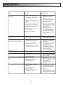
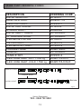
Installation Manual Shaker Dual Control Thermostatic Intergrated Shower Valve SSPC03 www.heritagebathrooms.com SSPC03 DESIGN REGISTRATION GRANTED PATENTS 800399 800399/B 00911649-0019 UK: Gb2426564 EU: Ep1893904 INTRODUCTION Thank you for buying the Heritage Semi-Intergrated Thermostatic Bolt through unit. The unit has undergone vigorous quality control procedures to ensure you receive a quality product. The unit has been factory pre-set to a temperature of 43°Celsius. Please read these instructions carefully and ensure the shower valve is installed to Local Water Authority regulations. If in doubt, contact a registered plumber or the Secretary of Institute of Plumbing, address as follows: Institute of Plumbing 64 Station Lane Hornchurch Essex RM21 6NB. Tel: 0170 847 2791 SITE REQUIREMENTS. To ensure the correct operation of your shower mixing valve it is important to fully understand your site installation. This valve will suit the following HIGH PRESSURE MAINS PRESSURE PUMPED PRESSURE UNEQUAL PRESSURE GRAVITY PRESSURE Please note:-The shower mixing valve may require slight adjustment depending on your site installation. See Fig 1. GENERAL. The installation, commissioning and maintenance must be carried out in accordance with instructions supplied and be installed by qualified and competent persons. 1) Before commencing isolating valves should be installed on both hot and cold supplies for flushing out and servicing purpose. 2) Both supply pipes must be flushed before connecting mixing valves to ensure no pipe/plumbing debris enters the mixing valve. 3) A simple way of flushing out the pipes is to fit the outlet adaptor to the pipe and secure with the compression nut and olive, fit the hose to the adaptor and flush out pipes to the waste. 4) Please fit strainers / filters supplied to ensure no debris enters the mixing valve. 5) In hard water areas the mixing valve may require more frequent de-scaling and cleaning and servicing. IMPORTANT INFORMATION This product is supplied with dish filters that go between the straight isolators and the non- return valve adaptors. Failure to fit these will invalidate the guarantee. TEMPERATURE CONTROL. Minimum cold water supply temperature: 5°C Maximum cold water supply temperature: 20°C Maximum hot water supply temperature: 85°C (a temperature of 60-65°C is recommended for ablutionary installations) Note! A suitable hot water temperature control device should be installed to reduce temperatures exceeding the above maximum hot water supply temperature. Minimum temperature differential between hot supply and outlet temperature: 10°C (eg. shower temperature 43°C: minimum hot supply 53°C) Factory pre-set temperature: 43°C. See Table 1. Minimum dynamic pressure: 0.2 bar Maximum dynamic pressure: 5 bar Maximum static pressure: 10 bar PERFORMANCE Pressure (Bar) Rose Handset (Spray Mode) 0.2 7.5 4.5 0.3 9.5 6 0.4 11 7 0.5 12.5 7.5 1 18 11 2 25 15.5 3 31 19 Table 1 The above flow rates are in L/min with no flow limiters fitted. 2 COMPATIBLE SYSTEMS Instantaneous heated system (Gas or Electric) Key Shower inc. non-return valves Isolating valve Tempering valve Pressure regulating valve Strainer Expansion vessel (optional) Twin Impeller Pump Gravity fed system Pumped system 10 metre Head Unvented mains pressure system Mains pressurised hot water system System includes: Expansion vessel Pressure relief valve Temperature relief valve Pressure reducing valve Energy cut-outs Fig 1 The above systems are typical types that this product will accommodate. If however your cold water supply to the valve is mains pressure then the following will apply:Hot supply above 5 metre (0.5 bar). Mains cold supply up to 10 bar. Fit 10 litre (yellow) limiter into cold inlet elbow & 6 litre (grey) into hot inlet. 3 INSTALLATION REQUIREMENTS GRAVITY FED SYSTEM. The distance between the bottom of the cold water tank and the shower head must be a minimum of 2 metre (0.2 bar). The cold water supply for the valve must be connected directly to the cold water tank and the hot water supply connected to an Essex or Sussex Flange in the side of the cylinder or to the vent and draw off pipe of the hot water cylinder, as close to the top of the cylinder as possible. INSTANTANEOUS GAS WATER HEATER & COMBINATION BOILER (UNVENTED). The hot supply from the heater is to be connected to the hot inlet flexi hose connection and cold inlet flexi hose connection to the cold supply. Fit 10 litre flow limiter (as supplied) into the cold non- return valve adapter prior to the non- return valve. INSTANTANEOUS (NON STORAGE). 7-9kw Electric Water Heaters (Unvented) This will require a 10 litre (yellow) flow limiter as supplied into Cold outlet only. IMPORTANT - It is a requirement of Instantaneous Electric Water Heaters that a stable flow of water passes through the heater. This requirement can be satisfied by using a Flow Stabilizer (Available from Plumbing stockist) and should be adjusted to give a temperature of between 50 & 55°C from the heater. PUMPED SHOWERS. Your Thermostatic shower is also ideal for power shower installation and can be matched to most makes of booster pump. For further information contact your local stockist. WATER BYLAWS. “Shower installation in all respects must meet with the requirement of Water Bylaws. If in doubt you should contact your local Water Authority for advice or a registered member of the Institute of Plumbers Tel: 0170 847 2791 for a list of your nearest plumbers. PIPE POSITION. Before finalising the position of the shower cubicle and showers, the position for the pipe work should be checked to ensure the manifold will not foul on the floor joists. The manifold can be rotated a full 360 degrees and can therefore be fed from any side of the room. It is essential that when installing your multi-function valve, full access can be achieved for servicing purposes. Underfloor access to the manifold is always preferred wherever possible, as this removes the need to disturb any flooring laid. 4 COMPATIBLE SYSTEMS For optimum performance from the thermostatic mixing valve, use the table below for Recommendations for flow limiter selection. See Table 2. The flow limiters should be fitted in the inlet ports of the inlet manifold. (See Fig 8) Supply System Flow Limiter Cold Supply Hot Supply Cold Hot 0.2 to 1.0 bar 0.2 to 1.0 bar N/A N/A 1 to 5 bar or Pumped 1 to 5 bar or Pumped Yellow (10 litre) Grey (6 litre) N/A N/A Comments Unsuitable # Use arrangement for pumped system, leave flow limiters out for better flow Gravity 0.2 to 0.2 bar N/A Gravity 0.2 to 1.0 bar Gravity above 1.0 bar Mains 1.5 to 10 bar Yellow (10 litre) Grey (6 litre) # Not required for the functionality of the shower valve Instantaneous Gas Water Heater Yellow (10 litre) Grey (6 litre) **# Not required for the functionality of the shower valve ***Instantaneous Electric Water Heater Yellow (10 litre) No **# Not required for the functionality of the shower valve Unvented Mains/ Mains Pressurised Table 2 # Limiters can be fitted if water economy is required. ** The bottom cap is factory set at 3/4 turn from fully closed position. *** IMPORTANT! - It is a requirement of Instantaneous Electric Water Heaters that a stable flow of water passes through the heater. This requirement can be satisfied by using a flow stabiliser fitted prior to the heater and should be adjusted to give a temperature of between 45-50°C from the heater. Note. Flow limiters can be obtained from calling the service department who’s number is on page 13 of this booklet. Mark Point Drawing for reference only. Fig 2 Remove wall bracket from mixing valve (see Installation). Peel off label to reveal Bottom Cap, with a marker pen, mark a point in-line with slot. Turn extra anticlockwise ½ (180°) turn using a screw driver. See Fig 2. 5 INSTALLATION 1) Before starting installation of the shower valve careful consideration must be taken to ensure when the Ø25 riser pipe is fed through the floor that this will not interfere with existing pipe work, joists or electrical equipment and adequate space exists between floors. 2) Once the Position to fit has been established and if all is well proceed to cut a Ø30mm (1 3/16”) hole through floor. 3) Hot and Cold water supplies are to be fed to the manifold assembly via 15mm copper or the optional flexi hoses See Fig. 12. These connect to the isolation elbow and the side inlet of the manifold. Cold feed to the side inlet of the manifold and the hot feed to the isolating elbow. Flexible hoses can be used by utilising the flat face adaptors or 15mm copper can be used utilising the compression nut and olive. Ensure filters, flow restructures and check valves are in place to protect the system. NOTE:-Failure to fit both filters will invalidate the guarantee. Care should be taken if using flexi hoses that the hoses don’t get crushed or kinked at any point as this will reduce the flow through the shower. See Fig 8 Note 1: An access panel will be required to attach the manifold to the inlet tubes beneath the shower tray, also it is advisable to have an access panel near the other end of the flexible hoses for servicing purposes. With access panel on the wall and floor. The two inlet tubes are 915mm long as supplied, the 25mm tube needs minimum of 57mm cutting off using pipe cutters (do not use hacksaw) to give the required 57mm differential between the two tubes. See Fig 4. Both tubes can be reduced even more to suit installation but the 57mm differential must be maintained. Also the 25mm tube must be long enough to get the manifold on with the tray in position. 4) Feed the tube into the floor then place the Ø15mm brass tube inside the Ø25 chrome tube and push into the manifold taking care to not damage the o-ring inside the Manifold body as this must provide a watertight seal. Secure the Ø25mm tube using the Compression nut. (Use 38mm a/flats spanner). Ensure watertight seals. Note 2: The Hot water will be fed to the valve via the Ø15mm tube and the Elbow Isolator. The Cold water is fed to the valve via the Ø25mm tube and side inlet of the Manifold forming a cooling jacket around the Hot supply. 5) Place the floor rose and clamp ring onto the Ø25mm riser. See Fig 8 Note. To ensure a water tight seal between the Ø25mm tube and the tray, use bathroom sealant to seal the floor rose to the tray, the rose has an O ring in it’s bore to seal the Ø25mm tube. 6) Now with the Ø15mm hot and Ø25mm cold inlet pipes to the valve sticking vertically up out of the shower tray, it is time to fit the vertical dual control shower valve to the inlet pipes and the glass screen that already has the pre-drilled holes, ready for the installation. 7) Remove the cubicle backplate off the valve by releasing the two grub screw retainers using a 2.5mm allen key. Remove the backplate by undoing the connecting bolt using a 2.5mm allen key. Remove the external flow handle off the valve by removing the large and small levers to reveal the grub screw which must be loosened to remove handle. Once the handle is removed the lock nut can be removed using 20mm a/flats spanner. See Fig 7 8) Place the cubical backplate on the inside of the glass at the bottom valve locating hole of the glass. Place the backplate cover on the outside of the glass and clamp both items together with the connecting bolt. Apply a force of no greater than 10n/m. 9) Lubricate the 15mm brass tube using washing up liquid to help internal o-ring to slide over tube to create water tight seal. 10) Place the shower valve over the riser and push fit the Ø15mm and Ø25mm tubes into the body with the o ring in place for the Ø15mm tube, to ensure a water tight seal. Lightly nip the 25mm nut and olive. See Fig 8. 11) Line up the body to the cubicle and the spindle with the second hole, lock body in place using the lock nut and external shroud Fix the shower valve to the cubicle backplate, secure using the 2 grub screws . 12) Align the external shroud with the top valve locating hole and secure in place using the lock nut. Apply a force of no greater than 10n/m. 13) Do the final tightening of the 25mm nut and olive. Care should be taken not to put excessive force on the shower screen. 14) Re-fit the external flow handle, secure using the grub screw, re-attach the large and small levers to the handles. See Fig 7. 15) If not already fitted to the valve , Screw on the short extension tube and shroud to the top of the valve. 16) Connect the Diverter to the short extension tube using the 25mm nut and olive supplied. See Fig 5. 17) Screw the shower hose onto the diverter swivel elbow and attach handset. Please note there should be a rubber washer between each of these connections to prevent water leaks. See Fig 6. 18) Position the top support bracket on the overhead tube to be in line with the pre-drilled hole in the glass, once the tube has been fitted to the top of the diverter using the 1” nut and olive. Fit support bracket to glass using relevant fittings. Apply a force of no greater than 10n/m. Note the handset slider bracket must already be on the overhead tube prior to fitting as it cannot be put on after the tube is fitted to valve. 19) The overhead bracket can now be secured to the assembly, and the end bracket can be fitted to solid wall by means of the wall fixing. Note there is an adjustment of between 800 and 900 mm to allow for differing widths of showering cubicles. See Fig 3. Once you are satisfied with the position fully tighten all compression fittings to ensure watertight seals. Fit overhead shower rose. 20) Establish the water supply to product and check for leaks. Tighten compression fittings if and where necessary. 21) The Shower Valve is factory set with a maximum temperature of 43°Celsius. Due to system variations, the product should always be re- calibrated to achieve the correct maximum working temperature. Please refer to Maximum Temperature Setting. See Fig 9. 6 SEMI-INTERGRATED BASIC DIMENSIONS. The line drawing below, Fig 3, shows the dimensions for the semi-intergrated shower valve. All dimensions are in mm. Note: Items being secured to the shower screen in positions A B and C should be at a maximum torque of 10n/m. 915.0 as supplied Hot and Cold feeder tubes A B C Fig 4 Fig 3 7 SEMI-INTERGRATED VALVE BLOW-OUT DRAWING O Rings Diverter Cover Diverter Adaptor Glass screen Swivel Elbow Adaptor O Ring Rubber Washer Large Lever Diverter Body Fibre Washer 1” Diverter Adaptor 1” Olive 1” Compression Nut Diverter Handle Diverter Body Grub Screw Small Lever Diverter Cartridge Diverter Swivel Elbow Grub Screw Grub Screw DIVERTER BLOWOUT DIVERTER SWIVEL ELBOW BLOWOUT Fig 6 Fig 5 1” Tube Valve Top Shroud 1” Extension tube 13 12 Bolt thro’ shower valve Flow Handle Connecting bolt Large Lever Grub screw Spindle assembly Flow handle Small Lever Temperature handle Cartridge 25mm Olive 25mm Comp.Nut 10 VALVE BLOWOUT Valve Bottom Shroud Lock nut External shroud Backplate cover Fig 7 Backplate / backcap Cubical backplate Ø25mm Cold inlet Ø15mm Hot inlet 4 O Ring Floor rose 5 Floor 25mm Compression Nut 25mm Olive O Ring Flat face adaptors Cold inlet Inlet Manifold OR 15mm Compression Nut & Olive Check Valve Flow Restrictor Filter Fibre Washer Flat face adaptors Hot inlet MANIFOLD BLOWOUT OR 15mm Compression Nut & Olive Fig 8 8 Maximum Temperature Setting The shower valve is factory set to 43°C maximum but may require calibration on installation. If necessary adjust as below 1) Turn the temperature handle anti-clockwise to the maximum (hottest) temperature position. 2) Remove the spokes, unscrew grub screw, then pull off handle. See Fig 9. 3) Turn valve on to maximum flow, (anti-clockwise if facing valve from inside the cubicle and clockwise from the external control). 4) Using a 2.5mm allen key through the head of the cartridge, turn the adjusting screw to alter the temperature. > Turn the adjusting screw clockwise for cooler temperature. > Turn the adjusting screw anti-clockwise for warmer temperature. The temperature should be set to a maximum of 43°C for user safety. Hotter temperatures may cause serious injury. 5) Replace the temperature handle. Flow control Temperature control Fig 9 9 SERVICE MAINTENANCE If your thermostatic mixing valve fails to operate it could be the result of incorrect installation. Please refer to installation and site requirements. If the valve has operated correctly for a time, but no longer performs acceptably, it may require servicing/cleaning. Proceed as follows; 1) Isolate water supplies by turning shut offs through 90°(flat blade screwdriver required) . 2) Unscrew Temperature and Flow handle spokes to expose M5 grubscrew. Remove this using 2.5mm allen key and remove all three control handles. See Fig 10. 3) Remove the temperature headwork assembly using a 32mm a/flats spanner. 4) Remove the flow control headwork including the spindles. 5) Remove the thermostat, piston assembly and spring. 6) Remove all visible ‘o’ rings and washers from the body. Ensure that you don’t damage the faces of the piston. Flow control Temperature control 32mm spanner required (standard thread). Ensure that you DO NOT damage the valve, pipe work or backplate when undoing the headwork. Fig 10 CLEANING AND LUBRICATION 1) Soak all metal parts in descalent, wash off in clean water. 2) Examine all o-rings and replace if necessary. 3) Use silicon based grease on all seals (light smear only). A maintenance kit is available, which contains all seals and grease from your local stockist or manufacturer. 10 RE-ASSEMBLY (You may find it easier to take the unit off the glass and hold it horizontally to re-assemble) 1) Replace the spring in the bottom of the valve followed by the piston assembly and thermostat. See Fig 11. 2) Screw the cartridge assembly into the barrel valve, taking care not to cross thread, and fully tighten. 3) Replace the spindle assembly, and fully tighten, after checking for correct operation and damage. NOTE- Do not adjust the backcap unless you are installing a new cartridge. If this is the case, screw the bottom cap fully clockwise until it stops, then unscrew anti-clockwise 3/4 turn only. See Fig 2. Fig 11 GENERAL FAULT DIAGNOSIS If your Thermostatic Mixing Valve fails to operate either immediately upon installation or after a period of time, the following points should be checked; 1) Isolate supplies and ensure that both hot and cold supplies are reaching the valve body. You may need to dis-connect supply pipes to ensure this. 2) Ensure that there is no debris between the faces of the piston and it’s mating faces, the bottom of the valve body and the cartridge. 3) Check that the valve has been installed correctly in accordance of its particular feed system (i.e use of flow limiters where necessary). 4) Check that the hot water temperature source is sufficient; preferred minimum of 60°C. 5) Refer to fault finder chart. See Table 3. Please note ALL drawings in this booklet are reference only. 11 FAULT FINDER Fault Cause Rectification No or reduced flow and/or fluctuating temperature. - Shower head blocked. - Isolating valve partially closed. - Instantaneous boiler cycling on and off as flow rate/pressure too low. - - Bottom cap setting incorrect. - Gravity head of water below minimum required. - Blockage in supplies/mixing valve. - - Other draw offs in use causing pressure or temperature changes. - Supply pressures unequal. - Flow limiters incorrectly fitted. - Air lock in system. - Shower cross circulating. - Clear debris from shower head. Open valve. Adjust bottom cap setting. Check boiler settings are correct. Contact boiler manufacturer. Adjust bottom cap setting. Raise tank or fit pump. Dismantle and check for debris. Flush supplies before refitting. Do not use other draw offs whilst showering. See maximum pressure differential in Specifications. Check Application Selection. Check System Requirements for correct installation method. Check non return valves and condition of seals. Maximum outlet temperature too hot or - Maximum temperature incorrectly set. too cold. - Reset maximum temperature. Refer to Instructions. Maximum temperature too cold or runs - Hot water is less than 10°C above the cold after a short time (maximum outlet temperature required. temperature set or fully adjusted). - - Instantaneous boiler not igniting as water flow rate/pressure too low. - Adjust tank temperature to 6065°C. Ensure hot water is up to temperature. Check tank or heater capacities. Low capacity equals shorter showering time. Adjust bottom cap setting. Increase flow through system. Increase pressure in system. Check for blockages. Contact boiler manufacturer. - Flow limiters incorrectly fitted. - Check Application Selection. - Inlet supplies reversed/backwards. - Ensure supplies are connected correctly to hot and cold inlets. Clean out debris. - Insufficient hot water supply or storage (running out of hot water). Outlet flow too much. Only hot or cold water at outlet Shower will not shut off or leaking from body. - No thermostatic fail safe. Inlet supplies blocked. - Seal damage or wear. Scale build up inside mixer. Inlet pressures above maximum recommendations. - - Inlet temperatures not within specification. - - - Piston assembly jammed. Thermostat failure. Debris trapped in mechanism. Inlet supplies reversed. - Renew all seals. Dismantle and check for debris. Ensure supply pressures are within Specification. Fit pressure regulating valve if necessary. Check inlet temperatures, hot supply should be 10°C higher than shower outlet temperature. Dismantle and check for debris. Replace thermostat. Dismantle and check for debris. Ensure supplies are connected correctly to hot and cold inlets. Table 3 12 SPARE PART ORDERING CODES DESCRIPTION VALVE SEALS KIT MANIFOLD ASSY. DIVERTER ASSY. VALVE CARTRIDGE SPINDLE ASSY. VALVE INLET TUBES 10" SHOWER ROSE THERMO & PISTON PISTON ASSY. THERMOSTAT ONLY CHROME HOSE HANDSET HANDLE SET FLEXI HOSE INLET -HOT 1.7Mtr Lg FLEXI HOSE INLET -COLD 1.7Mtr Lg ORDERING CODE SK1400-1 SKINLET-14 SKSS03-1 SK1400-4 SK680000 SK760602CP SK760888CP SK1500-3 SK320078 SK740012 SK420104CP SK730968CP SKSS03-2 SK420118-HOT SK420118-COLD SK420118-COLD Cold inlet Flexible Hoses Hot inlet SK420118-HOT Fig 12 Service Department TEL . 0844 701 8503 13 HERITAGE GUARANTEE All products are manufactured to the highest standards and 5-year guarantee covers any defect in manufacture. In the unlikely event that you encounter a problem with your Heritage bathroom products, you should, in the first instance, return to the retailer who supplied you. They will advise whether it is due to faulty product or faulty installation. If the problem is due to a manufacturing fault, they will contact Heritage to arrange supply of a replacement product as soon as possible. The guarantee excludes damage caused by accident, misuse or neglect and does not cover the following: Those components subject to wear and tear such as 'O' rings and washers etc, Damage caused by faulty installation, Damage caused by any waterborne debris, Damage caused by improper cleaning products, Damage caused by the use of non-Bristan parts, The product being used for a purpose other than intended. The company reserves the right, in the event of a claim not covered by the guarantee, to charge the claimant for parts and labour at current rates. This guarantee is given in addition to and does not affect your statutory rights. In the interests of continuous product development we reserve the right to alter the specification as necessary. If you require further assistance please contact Heritage Sales and Technical Enquiries: Sales: 0844 701 8501 Technical: 0844 701 6245 Technical fax: 0844 701 6246 Heritage Bathrooms Unit 6 Albert Road St Philips Central Bristol BS2 0XJ UK www.heritagebathrooms.com 14