1
TC12 Installation, Commissioning & Maintenance Handbook
SIEMENS TRAFFIC CONTROLS
Sopers Lane
POOLE
Dorset
BH17 7ER
SYSTEM:
TC12
TC12
Installation, Commissioning
and Maintenance Handbook
PREPARED: A Pickering
FUNCTION:
Engineer
This document is electronically held and approved in Meridian
© Siemens plc. 1997 - 2004 All rights reserved.
The information contained herein is the property of Siemens plc. and is supplied without
liability for errors or omissions. No part may be reproduced or used except as
authorised by contract or other written permission. The copyright and the foregoing
restriction on reproduction and use extend to all media in which the information may be
embodied.
666/HE/43100/000
Page i
Issue 10
TC12 Installation, Commissioning & Maintenance Handbook
Appendix A consists of the latest issue of 667/HB/26628/000.
The current issue of the following A3 drawings are included in the back of this manual:
667/CA/22741/000
667/DZ/22600/000
667/GA/22600/000
667/GA/22603/000
667/GA/22626/000 and 001
667/GA/22635/000
667/GA/22654/000 and 001
667/GA/22670/000
667/GA/22693/000
666/HE/43100/000
Page ii
Issue 10
TC12 Installation, Commissioning & Maintenance Handbook
SAFETY WARNING
In the interests of health and safety, when using or servicing this equipment the
following instructions must be noted and adhered to:
Only skilled or instructed personnel with relevant technical knowledge and experience,
who are also familiar with the safety procedures required when dealing with modern
electrical/electronic equipment are to be allowed to use and/or work on the equipment.
All work shall be performed in accordance with the Electricity at Work Regulations 1989.
Such personnel must take heed of all relevant notes, cautions and warnings in this
handbook, the General Handbook (666/HB/43100/000) and any other document or
handbook associated with the equipment.
The equipment must be correctly connected to the specified incoming power supply.
The equipment must be disconnected/isolated from the incoming power supply before
removing protective covers or working on any part from which protective covers have
been removed.
The Outstation PCB contains a lithium battery that must be disposed of in a safe
manner. If in doubt as to the correct procedure refer to Siemens Instructions CP562
Only authorised/trained personnel are allowed to have access behind the doors/panels
of the TC12 Instation Cabinet. Users/operators must not attempt to access anything
behind these doors/panels.
Only an authorised/trained person (trained in the safety aspects of working on mains
powered equipment) is allowed to setup/change any switch positions in the Instation
equipment and/or use any of the free mains sockets within the equipment and/or
connect/use the TC12 Instation Test Set at the Instation.
If the Audible alarm on the system fault indication panel (SIP) sounds it should be
cancelled as required from the UTC TCC terminal. If the reason for the alarm is a
UTC TCC failure, an authorised/trained person (trained in the safety aspects of
working with mains powered equipment), should be asked to cancel the audio alarm,
using the audio off switch on the PSU PCB.
666/HE/43100/000
Page iii
Issue 10
TC12 Installation, Commissioning & Maintenance Handbook
TELECOMMUNICATIONS APPROVAL WARNING
The Siemens TC12 Modems 667/1/22669/000, 667/1/22668/000 and 667/1/22668/001
and the TC12 OTU/LMU PCB Assemblies 666/1/02262/001 and 666/1/02262/021 are
Approved for connection to British Telecommunications Private Circuits in a Multipoint
or Point to Point configuration as defined in BS6328: Part 1: 1982, subject to the
conditions set out in the instructions for use.
TC12 Modems
Approval Number: NS/1143/2/N/603301
Date: 18/8/92
TC12 OTU/LMU PCB
Approval Number: NS/1143/2/N/603385
Date: 10/11/92
Integral OTU kit
(677/1/27004/000)
The Modem apparatus is intended for use when supplied with power from a source with
the following characteristics: +5 V (700 mA), +12 V (110 mA) and –12 V (160 mA).
Ensure that the power drawn by this modem together with any other auxiliary apparatus
drawing power from the host lies within the rating of the host power supply.
The OTU/LMU is intended for use when supplied with power from a source with the
following characteristics: +5 V (2.2 A), +24 V (250 mA). Ensure that the power drawn by
the OTU/LMU together with any other auxiliary apparatus drawing power from the host
lies within the rating of the host power supply. Other usage will invalidate any approval
given to this apparatus if as a result it ceases to comply with BS6301: 1989.
The Integral OTU apparatus is intended for use when supplied with power from a
source with the following characteristics: +5 V (2.2 A), +24 V (250 mA). Ensure that the
power drawn by the Integral OTU together with any other auxiliary apparatus drawing
power from the host lies within the rating of the host power supply.
This apparatus is NOT suitable for connection to the PSTN or to circuits with British
Telecommunications signalling at a nominal frequency of 2280 Hz. It is not intended that
there shall be any DC interaction between this apparatus and British
Telecommunications private circuits, nor does this apparatus use the frequency range
DC to 200 Hz.
The approval of this apparatus for connection to British Telecommunication Private
Speechband circuits is INVALIDATED if the apparatus is subject to any modification in
any material way not authorised by STC.
All apparatus connected to this modem and thereby connected directly or indirectly to
British Telecommunication Private Speechband circuits must be approved apparatus
defined in Section 16 of the British Telecommunication Act 1981.
The Siemens TC12 Instation 667/1/22600/ETC, TC12 Freestanding OTU/LMU
667/1/22670/ETC and TC12 Integral OTU 667/1/21611/100 are CE marked and self
certified to Directive 99/5/EC R&TTE.
666/HE/43100/000
Page iv
Issue 10
TC12 Installation, Commissioning & Maintenance Handbook
This Handbook must be supplied with the apparatus. Validity of the approval depends
on this information being supplied including the User Guide in the General Handbook
666/HB/43100/000.
666/HE/43100/000
Page v
Issue 10
TC12 Installation, Commissioning & Maintenance Handbook
TABLE OF CONTENTS
1
INTRODUCTION ................................................................................................. 1
1.1
PURPOSE ........................................................................................................... 1
1.2
SCOPE ................................................................................................................ 1
1.3
RELATED DOCUMENTS .................................................................................... 1
1.3.1
1.3.2
1.3.3
Parent Documents............................................................................................ 1
Kindred Documents.......................................................................................... 1
Reference Documents...................................................................................... 1
1.4
DEFINITIONS ...................................................................................................... 1
1.5
ISSUE STATE AND AMENDMENTS................................................................... 2
1.6
TC12 SYSTEM OVERVIEW ................................................................................ 4
2
TC12 INSTATION.............................................................................................. 10
2.1
SPECIFICATION ............................................................................................... 10
2.1.1
2.1.2
2.1.3
2.1.4
2.1.5
2.2
2.2.1
2.2.2
2.2.3
2.2.4
2.2.5
2.2.6
2.2.7
2.3
2.3.1
2.3.2
2.4
2.4.1
2.4.2
2.4.3
2.4.4
2.4.5
2.4.6
2.4.7
2.4.8
2.4.9
2.4.10
Mains voltage ranges ..................................................................................... 10
Mains frequency range................................................................................... 10
Mains current ................................................................................................. 10
Temperature and humidity requirements........................................................ 10
Size and Weight ............................................................................................. 11
INSTALLATION ................................................................................................. 12
Cabinet........................................................................................................... 12
PC .................................................................................................................. 13
Systems Fault Indication Panel (SIP) ............................................................. 22
19" Racking PCBs .......................................................................................... 22
Digital Output Rack, PCBs and PSUs ............................................................ 36
PSTN Modem................................................................................................. 39
External Cables .............................................................................................. 39
COMMISSIONING ............................................................................................. 44
Safety Tests on the TC12 Instation ................................................................ 44
Commissioning Procedure after Power Up .................................................... 46
MAINTENANCE................................................................................................. 47
Status LEDs ................................................................................................... 47
Effect of Incorrect Switch Settings on the PSU PCB ...................................... 48
Effect of Incorrect Switch Settings on the Modem PCB.................................. 49
Effect of Incorrect Switch Settings on the Transformer PCB .......................... 50
Effect of Incorrect Switch Settings on the Digital Output PCBs ...................... 50
Fault Finding at the Instation .......................................................................... 50
Replacing Modem, Transformer and Digital Output PCBs ............................. 52
TC12 Instation PC Help / Diagnostic Screens ................................................ 52
Fuses ............................................................................................................. 59
PSU................................................................................................................ 60
666/HE/43100/000
Page vi
Issue 10
TC12 Installation, Commissioning & Maintenance Handbook
2.4.11
2.4.12
Digital Output PCB ......................................................................................... 61
Recommended Spares................................................................................... 61
3
TC12 OUTSTATION.......................................................................................... 62
3.1
SPECIFICATION ............................................................................................... 62
3.1.1
3.1.2
3.1.3
3.1.4
3.1.5
3.1.6
3.2
3.2.1
3.2.2
3.2.3
3.2.4
3.2.5
3.2.6
3.2.7
3.3
3.3.1
3.3.2
3.3.3
3.3.4
3.3.5
3.4
3.4.1
3.4.2
3.4.3
3.4.4
3.4.5
3.4.6
3.4.7
Mains voltage ranges ..................................................................................... 62
Mains frequency range................................................................................... 62
Mains current ................................................................................................. 62
Temperature and humidity requirements........................................................ 62
Size and Weight ............................................................................................. 62
Detector Power Supply................................................................................... 62
INSTALLATION ................................................................................................. 62
General .......................................................................................................... 62
Configuring the Outstation PCB ..................................................................... 63
Connectors and Cables.................................................................................. 69
Lamp Monitor Unit Connections ..................................................................... 78
Current Transformer Ratings.......................................................................... 80
Lamp Monitor Unit - Number of Current and Voltage Sensors ....................... 83
TC12 Outstation Mechanical Modules and Number of Detectors Supported . 85
COMMISSIONING ............................................................................................. 86
Safety Tests on the TC12 Outstation ............................................................. 86
Commissioning Procedure after Power Up .................................................... 87
Configuration Using the Handset.................................................................... 88
Examples of Lamp Monitor Unit Configuration Using the Handset............... 119
TCSU TC12 OTU Commissioning Procedure .............................................. 130
MAINTENANCE............................................................................................... 132
Status LEDs ................................................................................................. 132
Effect of Incorrect Switch Settings on the OTU PCB .................................... 134
Fault Finding at the Outstation ..................................................................... 134
Fuses ........................................................................................................... 135
Lithium Battery ............................................................................................. 135
PSU.............................................................................................................. 135
Recommended Spares................................................................................. 137
4
TC12 INSTATION TEST SET.......................................................................... 138
4.1
SPECIFICATION ............................................................................................. 138
4.1.1
4.1.2
4.1.3
4.2
4.2.1
4.2.2
4.2.3
4.2.4
4.2.5
Mains voltage and frequency ranges............................................................ 138
Mains Current............................................................................................... 138
Size and Weight ........................................................................................... 138
INSTALLATION ............................................................................................... 139
Setting the Working Voltage Range Of the Instation Test Set...................... 139
TC12 Instation Test Set Software Installation .............................................. 139
Error Messages during Test Set Software Start Up ..................................... 139
Terminal Emulation Software ....................................................................... 140
Installation of Handset Software................................................................... 140
666/HE/43100/000
Page vii
Issue 10
TC12 Installation, Commissioning & Maintenance Handbook
4.3
OVERVIEW OF THE TC12 INSTATION TEST SET SETTINGS/SELECTIONS
AND CONNECTIONS................................................................................................. 141
4.3.1
4.3.2
4.3.3
Introduction .................................................................................................. 141
Connection to Unit Under Test ..................................................................... 141
Front Panel Switches ................................................................................... 142
4.4
OVERVIEW OF TEST SET SOFTWARE SETTINGS/SELECTIONS AND
OPERATION .............................................................................................................. 145
4.4.1
4.4.2
4.5
4.5.1
4.5.2
4.5.3
Modes of Operation...................................................................................... 145
Screens / Functions of the ITS ..................................................................... 145
USING THE TEST SET FOR FAULT FINDING ON TC12 SYSTEM ............... 147
General ........................................................................................................ 147
Starting up the Test Set................................................................................ 147
Fault Diagnosis............................................................................................. 148
4.6
USING THE TEST SET AS A MONITOR FOR THE INSTATION PC.............. 154
4.7
USING THE TEST SET AS HANDSET ........................................................... 155
4.8
MAINTENANCE OF INSTATION TEST SET................................................... 156
4.8.1
4.8.2
Recommended Spares................................................................................. 156
Periodic Testing............................................................................................ 156
5
TC12 OUTSTATION TEST SET...................................................................... 157
5.1
SPECIFICATION ............................................................................................. 157
5.1.1
5.1.2
5.1.3
5.2
5.2.1
5.3
5.3.1
5.3.2
5.3.3
Mains voltage and frequency ranges............................................................ 157
Mains Current............................................................................................... 157
Size and Weight ........................................................................................... 157
USING THE OUTSTATION TEST SET ........................................................... 158
Facilities ....................................................................................................... 158
OPERATION.................................................................................................... 163
General ........................................................................................................ 163
OTU Mode (Simulating an Outstation) ......................................................... 163
Controller Mode (Simulating Traffic Control Equipment) .............................. 164
5.4
MAINTENANCE............................................................................................... 166
6
INTEGRAL OUTSTATION TRANSMISSION UNIT (OTU/LMU) ..................... 167
6.1
GENERAL OVERVIEW ................................................................................... 167
6.2
SPECIFICATION ............................................................................................. 168
6.2.1
6.2.2
6.2.3
6.2.4
6.3
Mains voltage and frequency ranges............................................................ 168
Mains Current............................................................................................... 168
Temperature and Humidity Requirements.................................................... 168
Size .............................................................................................................. 168
INSTALLATION ............................................................................................... 169
666/HE/43100/000
Page viii
Issue 10
TC12 Installation, Commissioning & Maintenance Handbook
6.3.1
6.3.2
6.3.3
6.3.4
6.4
6.4.1
6.4.2
6.4.3
6.4.4
6.5
6.5.1
6.5.2
6.5.3
6.5.4
6.5.5
General ........................................................................................................ 169
Configuring the Integral OTU PCB ............................................................... 169
Connectors and Cables................................................................................ 172
Lamp Monitor Unit - Number of Current and Voltage Sensors ..................... 178
COMMISSIONING ........................................................................................... 179
Commissioning Procedure after Power Up .................................................. 179
Configuration Using the Handset.................................................................. 180
Examples of Lamp Monitor Unit Configuration Using the Handset............... 185
LMU Commissioning .................................................................................... 188
MAINTENANCE............................................................................................... 191
Status LEDs ................................................................................................. 191
Effect of Incorrect Switch Settings on the OTU PCB .................................... 191
Fault Finding at the Outstation ..................................................................... 192
Lithium Battery ............................................................................................. 192
Recommended Spares................................................................................. 192
FIGURES
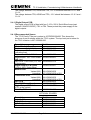
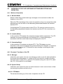
FIGURE 1 - SYSTEM DIAGRAM FOR DIGITAL OUTPUT RACK CONNECTION TO A
WALL MAP ................................................................................................. 8
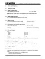
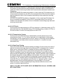
FIGURE 2 - SYSTEM CONNECTION FOR TWO ITU RACKS ...................................... 9
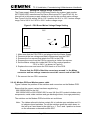
FIGURE 3 - TC12 CABINET - EXTERNAL DIMENSIONS ........................................... 11
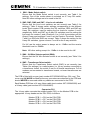
FIGURE 4 - TC12 INSTATION PC INSTALLATION SCREEN (7.4) ............................ 19
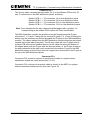
FIGURE 5 - TC12 INSTATION PC INSTALLATION SCREEN (8.3 & LATER)............. 19
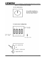
FIGURE 6 - ITU 19" RACK (FRONT VIEW) ................................................................. 22
FIGURE 7 - PSU BOARD LAYOUT ............................................................................. 25
FIGURE 8 - PSU BOARD SWITCH SETTINGS........................................................... 26
FIGURE 9 - PSU BOARD MAINS VOLTAGE RANGE SETTING ................................ 27
FIGURE 10 - MODEM PCB LAYOUT .......................................................................... 30
FIGURE 11 - TRANSFORMER PCB LAYOUT............................................................. 35
FIGURE 12 - ITU 19" RACK (REAR VIEW) ................................................................. 35
FIGURE 13 - DIGITAL OUTPUT PCB LAYOUT........................................................... 36
FIGURE 14 - MODEM PCB - MDF CONNECTIONS ................................................... 41
FIGURE 15 - TRANSFORMER PCB - MDF CONNECTIONS...................................... 43
FIGURE 16 - MODEM AND PSU PCB STATUS LEDS................................................ 48
FIGURE 17 - MASTER SWITCH PANEL FUSES ........................................................ 60
FIGURE 18 - OUTSTATION PCB LAYOUT ................................................................. 64
FIGURE 19 - OUTSTATION PCB AND DAUGHTER BOARD LAYOUT ...................... 64
FIGURE 20 - OTU LITHIUM BATTERY ON / OFF SWITCH (S2) ................................ 67
FIGURE 21 - OTU 2/4 WIRE SELECT SWITCH (S4) .................................................. 67
FIGURE 22 - OTU 600 Ω HIGH IMPEDANCE SWITCH (S6)....................................... 67
FIGURE 23 - MODEM DAUGHTER CARD JUMPER POSITIONS.............................. 68
FIGURE 24 - OTU 6-WAY TELECOM SOCKET CONNECTIONS............................... 70
FIGURE 25 - OUTSTATION INPUT CONNECTIONS.................................................. 73
FIGURE 26 - OUTSTATION OUTPUT CONNECTIONS.............................................. 74
FIGURE 27 - FREESTANDING OUTSTATION INPUTS.............................................. 76
FIGURE 28 - LMU INPUT CONNECTOR..................................................................... 78
666/HE/43100/000
Page ix
Issue 10
TC12 Installation, Commissioning & Maintenance Handbook
FIGURE 29 - PHASES IN STAGES FOR EXAMPLE 6 .............................................. 127
FIGURE 30 - OUTSTATION PCB STATUS LEDS ..................................................... 133
FIGURE 31 - OUTSTATION PSU VOLTAGE CHECKS............................................. 136
FIGURE 32 - OUTSTATION TEST SET FRONT PANEL........................................... 159
FIGURE 33 - OUTSTATION TEST SET CONNECTIONS ......................................... 160
FIGURE 34 - INTEGRAL OTU PCB LAYOUT AND SWITCH SETTINGS ................. 170
FIGURE 35 - LMU INPUT CONNECTOR................................................................... 175
TABLES
TABLE 1 - MODEM PCB MODE SELECT SWITCH (SW1) ......................................... 31
TABLE 2 - MODEM PCB LINE LEVEL SWITCHES (SW2, 3, 6 AND 7) ...................... 32
TABLE 3 - MODEM PCB 2/4 WIRE SELECT SWITCH (SW4)..................................... 33
TABLE 4 - MODEM PCB TRANSFORMER SELECT SWITCH (SW5) ........................ 33
TABLE 5 - OTU LINE LEVEL SWITCH (S3)................................................................. 68
TABLE 6 - OUTSTATION PROCESSOR PCB - PL1 ................................................... 79
TABLE 7 - TCSU DEFAULT CONFIGURATION VALUES ......................................... 131
TABLE 8 - INTEGRAL OTU LINE LEVEL SWITCH (S3)............................................ 172
TABLE 9 - INTEGRAL OTU PLA - 40 WAY CONNECTOR........................................ 172
TABLE 10 - INTEGRAL OTU SK2 SK3 - TEST JACKS ............................................. 173
666/HE/43100/000
Page x
Issue 10
TC12 Installation, Commissioning & Maintenance Handbook
1
INTRODUCTION
1.1
PURPOSE
This document is a guide for professional Installation and Maintenance personnel.
It describes how to install, commission and maintain the TC12 Instation and
Outstation.
1.2
SCOPE
Section 2 covers the Instation cabinet and all the equipment contained within the
TC12 Instation. Section 3 covers all equipment associated with the TC12
Outstation. Sections 4 and 5 describe the Instation and Outstation test sets.
Section 6 describes the integral OTU that may be fitted in T400 and ST800
controllers.
1.3
RELATED DOCUMENTS
1.3.1 Parent Documents
a) Requirements Specification for Data Transmission System, 666/UH/43100/000
issue 5.
1.3.2 Kindred Documents
a) General Handbook for the TC12 System, 666/HB/43100/000
b) Handbook for the TC12 Serial Environmental Monitor Sensor interface
667/HB/26628/000.
1.3.3 Reference Documents
a) Technical Handbook for Telecommand 8 Outstation Test Set, PTM112/01.
b) TRRL Supplementary Report 526, Automatic Incident Detection - TRRL
algorithms HIOCC and PATREG.
1.4
DEFINITIONS
IMD
ITS
ITU
LMU
MDF
OTS
OTU
PITS
PC
STC
TCC
UTC
666/HE/43100/000
Intelligent Modem Driver
Instation Test Set
Instation Transmission Unit
Lamp Monitoring Unit
Main Distribution Frame
Outstation Test Set
Outstation Transmission Unit
Portable Intelligent Terminal System
Personal Computer
Siemens Traffic Controls
Traffic Control Computer
Urban Traffic Control
Page 1
Issue 10
TC12 Installation, Commissioning & Maintenance Handbook
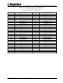
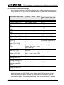
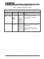
1.5
ISSUE STATE AND AMENDMENTS
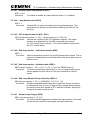
Issue 1 - First formal issue
Issue 2 - Significant changes this issue are listed below:
Table 3 and Table 6 Modem PCB and OTU PCB Receive threshold switch settings
for –39 dBm and –33 dBm were reversed in issue 1.
Instation recommended spares, PSU PCB and PSU added.
Modem PCB, Transformer PCB and OTU PCB all have covers - the part numbers
have been corrected.
Section 5 Outstation Test Set - connections have been corrected (Figure 27
updated), there are now 6 cableforms 666/1/22658/000 to 005.
Section on Outstation Test Set Controller Mode - Corrected OTS switch function
and LED indicator function in this mode.
Safety Tests on the TC12 Instation - updated to say that if rack or panel is
removed then earth continuity must be rechecked. PSU PCB OV added to earth
continuity tests.
Safety notes added in various places to state that only authorised/trained
personnel can access behind the doors/panels on the TC12 Instation.
PSU PCB Installation updated to include connection of an earth strap.
OTU Telephone connections updated since cable is terminated in a plug. Note
added about ferrite core being cable tied to stop it moving/interfering.
Instation PC Software Installation section and PC card switch settings updated.
Instation software - IMD information screen, layout of information corrected.
Modem PCB switch settings clarified (Figure (8) and Tables 2,3 and 5)
Paragraph added to Modem PCB section to clarify IMD distribution module
connections.
LMU Information Expanded and corrected:
Red Lamp monitoring has not been approved by the Department of
transport and should not be used.
Maximum Number of signal heads for current transformers updated,
including information on 50-0-50 operation.
Voltage sensors can only be used down to first dim tap when monitoring
50-0-50 supplies.
LMU input 24 is commoned with the ZXO (voltage monitor input).
Section added on the number of current and voltage sensors required.
Section added showing examples of LMU handset configuration.
• Section added on LMU Commissioning.
• Handset commands updated - GSA, GUD, GDI, KDI, KMS, KFD, KAD, KPT,
KRE, KLS.
• New handset commands added - KLV and GLT.
Issue 3 - Significant changes for this issue listed below.
Section 6 added, contains details of the Integral OTU - Export only.
Handset commands for High Occupancy software (HIOCC) added:
GHA, GHZ, GHV, GHL, GHN, GHF, and GHE.
New functions for HIOCC added to GRL command.
Setting up the 600R / High Impedance switch. Instructions now allow for Multi-drop
line configuration. Agreement with BABT or other line supplier to be sought before
use.
666/HE/43100/000
Page 2
Issue 10
TC12 Installation, Commissioning & Maintenance Handbook
Example of lamp monitoring on a more complex junction added.
Drawing of OTU input, and reply bytes added.
Replacement current sensor part number added. (667/7/25171/000)
• Replacement voltage monitoring transformer part number added.
(667/7/25172/000)
Issue 4 - Significant changes for this issue listed below.
• Handbook converted to Word v6.
• 667/HB/26628/000 OTU Serial Environmental Monitor handbook added.
• Remote Handset details added.
• OTU default values for TCSU added.
• OTU Handset commands GPV, KPV, GIU, KCF, KFS, KEV, KEL, GDO, GDT,
KML, GOT and KLP added.
• OTU Handset command GCT updated.
• Table 2 corrected.
• Additional Phase types added to handset commands KMS and KPT.
Issue 5 - Significant changes for this issue listed below.
• Cross references resolved
• Headers and footers updated
• Spelling corrected
• References to VAX changed to UTC TCC
• References to T400 changed to reflect addition of ST800 Controller
• Table 1 rewritten
• Table 2 amended
• 2.2.2.1 to 2.2.2.5 rewritten
• 3.3.3.4 amended
• 3.3.3.10 note added
• 3.3.3.24 text added
• 3.3.3.25 amended
• 6.4.2 table RFL command amended
• Figure 22 PL12 changed to PL2
• 3.2.3.5 Current Transformers and following text changed to heading 3.2.3.6
Current Transformer Ratings
Issue 6 - Significant changes for this issue listed below.
• Integral OTU now has BABT approval (leased line) and consequential
changes are:
• 6.1 amended
• 6.2.1.amended
• 6.3.1.amended
• 6.3.2.3 amended
• Table 8 amended to show prohibited power level settings
• Figure 1 and 2 redrawn (deleted in error from previous issue)
Issue 7 - Significant changes for this issue:
666/HE/43100/000
Page 3
Issue 10
TC12 Installation, Commissioning & Maintenance Handbook
• Equipment is CE marked and self-certified to RTE Directive 99/5/CE R&TTE.
BABT approval no longer appropriate. References to BABT removed
throughout document.
• Clarification to battery change procedures, sections 3.4.5 and 6.5.4.
• Instation Power Supply replacement procedure added to section 2.4.10.
• General updates to formatting and spelling.
• Preface removed, since the information it gave is available from the table of
contents.
Issue 8 - Significant changes for this issue:
• Changes to reflect introduction of RS232 OTU communications interface.
• Instation software installation procedure revised
Issue 9 - Significant changes for this issue:
• Changed OTU PCB part number to /100 from /001 and added Integral OTU kit
part number to section 6.5.5.
• Added TC12 inputs specification to section 3.2.3.5.
• Edited section 3.4.1 – Status LEDs.
• Added codes 83-91 to Function Group 1 of Display Fault Data section
3.3.3.28.
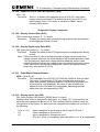
Issue 10 - Significant changes for this issue (Oct 2011):
• Added new Remote Handset Mode handset command GRH to section
3.3.3.87
• Added new Echo/Repeat Display Disable handset command ERD to section
3.3.3.51
• Added “Also see the ERD command” to notes on section 3.3.3.67
1.6
TC12 SYSTEM OVERVIEW
TC12 is a telecommunications system designed for Urban Traffic Control (UTC). It
consists of a number of Outstation Transmission Units (OTUs) positioned in the
traffic controllers or detector cabinets. These communicate with a central office
containing a number of Instation Transmission Units (ITUs). Communication
between the two is by means of private wire telephone lines, which can be
operated at different baud rates and signal levels.
The ITU sends a Control message to the OTU that will cause the OTU to form the
appropriate Reply message, which it will send back. These messages are of
configurable size depending on the amount of data transfer needed.
The ITU connects to a Traffic Control Computer (TCC) system consisting of one or
more UTC TCC computers and one or more PCs communicating with each other
via an Ethernet link. This system drives the ITU modems, which communicate with
the OTU via the telephone lines.
The ITU also drives the System Fault Indication Panel (SIP) which indicates, by
means of LEDs and an audible alarm, failures in the TCC. The SIP is housed in
666/HE/43100/000
Page 4
Issue 10
TC12 Installation, Commissioning & Maintenance Handbook
the ITU cabinet but there is also the option of driving a remote SIP. The ITU can
also be used to drive a TC8 Instation.
There is also facility for an Instation Test Set which can be used to measure signal
levels and monitor communications (both data and errors) on the telephone lines.
It can also be used to take the place of either Instation or Outstation for testing.
The Outstation test set is used in place of the controller to both set Reply bits and
monitor Control bits at the OTU.
666/HE/43100/000
Page 5
Issue 10
TC12 Installation, Commissioning & Maintenance Handbook
Instation
The Instation comprises of one or more Traffic control computers (TCC) and one
or more Instation Transmission Units (ITUs). The ITU cabinets are 32U high with
grey panelling and a smoked glass front door.
Traffic Control Computer
The TCC is a system containing a minimum of one machine and one PC per ITU
cabinet. The UTC TCC system communicates with the PC(s) via an Ethernet link.
More than one UTC TCC will be used should the number of modems required
demand it.
Instation Unit
The ITU cabinet is fitted with a PC at the top, and space for up to four racks below
it. These racks will be either ITU or Digital output racks, but the bottom space can
be used for an OTU if required. There is also a mains distribution system with
spare sockets, and facility for mounting a PSTN modem that would connect to the
UTC TCC to allow remote interrogation.
System Fault Indication Panel
The System Fault Indication Panel (SIP) is positioned in front of the PC and
houses LEDs to warn of various failures. There is also an audible alarm on the SIP
that can be cancelled by a switch next to it or disabled by a switch on the PSU
board.
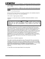
ITU Rack
A full ITU rack contains three types of board; four modem boards, four transformer
boards and a power supply board.
The modem board has four modem chips that communicate with the PC via a V.24
link. These modems are connected to the OTU via the telephone lines in either
radial, multidrop or multipoint format. There is also a pair of test jacks on the
modem board to allow connection to the Instation test set to monitor
communications data and measure signal levels.
The transformer board is used, when the system is in radial configuration, to split
each modem to up to eight telephone lines. This gives a maximum of 128
telephone lines per rack.
The PSU board supplies power to the ITU rack. It also interfaces between the PC
and the SIP and allows connection to a TC8 ITU rack. This facility would be used
should a TC8 system be expanded with TC12.
666/HE/43100/000
Page 6
Issue 10
TC12 Installation, Commissioning & Maintenance Handbook
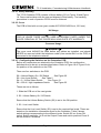
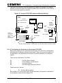
Digital Output Rack
The Digital output rack contains one Instation rack Power Supply Card and
between one and sixteen Digital Output boards, each capable of driving 64 LEDs
at up to 30 V 25 mA. There are two variants of Digital Output board, one sources
current and the other sinks current. The system could be used for any application
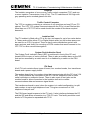
requiring digital output, not just wallmap driving.
Instation Test Set
The Instation Test Set (ITS) is housed in an attaché case, and connects to either
the Modem PCBs or the OTU PCBs. It contains a PC, a modified ITU modem
board, an ITS logic board and two power supplies. One power supply is the same
unit as on the PSU board in the ITU rack and is used to power both the boards,
whilst the other is the PC PSU. The ITS provides for connection to the Modem or
OTU board as well as use as a handset.
Outstation Test Set
The Outstation test set is a portable unit housed in a small grey metal case. It
requires a mains supply for operation and two cable forms with which to interface
with the OTU being tested.
Freestanding Outstation
The freestanding outstation is a rack that can be bolted into any Traffic Controller.
It contains a Power Supply, an OTU PCB and up to four detector PCBs. Two
connectors allow the OTU inputs and outputs to be wired up to the controller and
or detector cards, and the OTU is delivered with a cable for this purpose. The
outstation can also provide an LMU facility, and a connector allows current and
voltage monitoring transformers to be attached for this purpose. There is a pair of
test jacks on the board to allow connection to the Instation test set to monitor
communications data and measure signal levels.
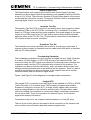
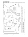
Figure 1 and Figure 2 show diagrams of example system connections.
Integral OTU
The integral OTU is a printed circuit card that can be installed in a T400 or ST800
Traffic Controller. It is a version of the T400 Ancillary processor with suitable
firmware to configure it to be an OTU. A single 40-way ribbon cable connector
supplies communication to the controller and all power. A 60 way ribbon cable
connector is fitted for connection to current and voltage monitoring transformers
for use as an LMU. There is no provision for detector inputs - the controller
supplies all detector information.
Connection to the line is via a captive lead terminated in a 6-way BT plug.
There is a pair of test jacks on the board to allow connection to the Instation test
set to monitor communications data and measure signal levels.
666/HE/43100/000
Page 7
Issue 10
TC12 Installation, Commissioning & Maintenance Handbook
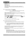
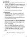
Figure 1 - System Diagram for Digital Output Rack connection to a Wall Map
666/HE/43100/000
Page 8
Issue 10
TC12 Installation, Commissioning & Maintenance Handbook
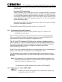
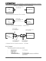
Figure 2 - System Connection for two ITU Racks
666/HE/43100/000
Page 9
Issue 10
TC12 Installation, Commissioning & Maintenance Handbook
2
TC12 INSTATION
2.1
SPECIFICATION
2.1.1 Mains voltage ranges
The Instation will work over: 98 – 132 V RMS
198 – 264 V RMS
Note. The voltage range of the PC used in the Instation should be checked in the
manufacturer's literature and note should be taken of any links/switches
that need setting for different voltage ranges.
2.1.2 Mains frequency range
All TC12 equipment will work from 47 Hz to 63 Hz
2.1.3 Mains current
Instation Cabinet and PC without racks
ITU Rack (Fully equipped)
1.0 A @ 240 V
200 mA @ 240 V
Digital Output Rack (Fully equipped)
1024 LEDs at 24 V 25 mA per LED
4.5 A @ 240 V
Digital Output Rack (Fully equipped)
1024 LEDs at 24 V 15 mA per LED
2.75 A @ 240 V
The figures above are added together for the system used:
An ITU cabinet with two ITU racks will use:
1.0 + 0.2 + 0.2 =
1.4 A
An ITU cabinet with two 15mA Digital output racks will take:
+ 2.75 + 2.75 =
6.5 A
2.1.4 Temperature and humidity requirements
The ITU will work over:
0 °C to 40 °C
Humidity:
666/HE/43100/000
20%-80% non-condensing
Page 10
Issue 10
TC12 Installation, Commissioning & Maintenance Handbook
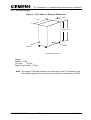
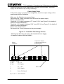
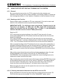
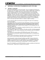
2.1.5 Size and Weight
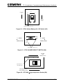
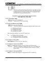
Figure 3 - TC12 Cabinet - External Dimensions
585
875
1540 1625
SIDE
FRONT
All dimensions in mm
Weight:
Cabinet 111 Kg
ITU Rack
8.4 Kg
Digital Output Rack 8.3 Kg
Note: The weight of the cabinet does not include any of the PC equipment, and
the weights specified for the racks are with their full complement of PCBs.
666/HE/43100/000
Page 11
Issue 10
TC12 Installation, Commissioning & Maintenance Handbook
2.2
INSTALLATION
Safety Notes on TC12 Instation
Only authorised/trained personnel are allowed to have access behind the
doors/panels of the TC12 Instation Cabinet. Users/operators must not attempt to
access anything behind these doors/panels.
Only an authorised/trained person (trained in the safety aspects of working on
mains powered equipment, is allowed to setup/change any switch positions in the
Instation equipment and/or use any of the free mains sockets within the equipment
and/or connect/use the TC12 Instation Test Set at the Instation.
If the Audible alarm on the system fault indication panel (SIP) sounds it should be
cancelled as required from the UTC TCC terminal. If the reason for the alarm is a
UTC TCC failure, an authorised/trained person (trained in the safety aspects of
working with mains powered equipment), should be asked to cancel the audio
alarm, using the audio off switch on the PSU PCB.
On site safety tests, as described in section 2.3.1, must be carried out before the
Instation is attached to the mains. If after the on site earth continuity test, any rack
or panel is removed or replaced, then the earth continuity check to that item
should be repeated.
2.2.1 Cabinet
The TC12 Family Tree part number is 667/DZ/22600/000. This shows the
structure of part numbers within the TC12 system. The top-level part number for
the TC12 Instation is 667/1/22600/000.
The racking space is 32U high, and contains five 6U positions and one 2U
position, refer to drawing 667/GA/22600/000 which shows the position of the major
components fitted to the cabinet. These include:
Master Switch Panel Assembly fitted to rear of cabinet, height 2U
(667/1/22603/000)
Mains Socket Assembly, fitted to front of cabinet, height 2U (667/1/22605/000)
System Fault Indication Panel (FIP), height 6U (667/1/22667/000)
TC12 PC Mounting Chassis (667/2/22621/000)
IMD Distribution Mounting Panel (667/2/22636/000)
Additionally 1 or more TC12 19" Instation Racks (height 6U, refer to separate
drawing 667/GA/22626/000) will be fitted - these contain PSU PCBs, Modem
PCBs and possibly Transformer PCBs, all of which are described in later sections.
The Instation may contain 19" Digital Output Racks (height 6U, refer to drawing
667/GA/22626/001) as well as, or instead of TC12 19" Instation Racks.
Optionally a TC12 Outstation can also be fitted to the Instation cabinet, for test
purposes. The Outstation is 5U high and therefore, if fitted, a 1U blanking panel is
also included (667/1/22613/000)
666/HE/43100/000
Page 12
Issue 10
TC12 Installation, Commissioning & Maintenance Handbook
Unused 6U positions are fitted with a 6U blanking panel
(561/4/20899/022)
2.2.2 PC
The TC12 PC is not like most PCs in that it does not have a motherboard;
instead the processor card and the other cards are plugged into a back plane.
There are 2 types of TC12 PC which may be used and are described below:
2.2.2.1 Rack Mount PC
The Rack Mount PC is a convention desktop style of PC which sits on a shelf in
the TC12 cabinet. It has a conventional keyboard attached to it and needs a
separate monitor for software installation and any checking of its operation.
2.2.2.2 Flat Panel PC
The Flat Panel PC may be used in situations where a compact TC12 Instation is
required. The PC is normally mounted in a 19” rack and has an integrated LCD
screen and membrane keyboard.
2.2.2.3 TC12 PC Operating System
The TC12 PC software uses DOS as its operating system. The TC12 PC
normally comes with DOS pre-installed. If, however, if DOS is not installed then
the PC manufacturer's set up instructions should be followed.
SAFETY NOTE!
When initialising the PC, check the working voltage range of the PC is
suitable for the mains supply that is going to be used. Follow the
manufacturer's instructions for any switches/links etc., which need to be
changed in order for the PC to work with the intended mains supply.
2.2.2.4 TC12 PC Configurations
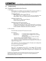
The following combinations of TC12 PC may be used:
2.2.2.4.1 Rack Mount Data Transmission PC
A rack mount PC which is to be used for data transmission would normally have
the following, additional, cards installed in it.
• Ethernet Card (Etherlink 3) (not needed if processor card has built-in
Ethernet)
• Digi I/O Card
• Intelligent Modem Driver Card (IMD) either Xi or Xe (1 per ITU rack)
666/HE/43100/000
Page 13
Issue 10
TC12 Installation, Commissioning & Maintenance Handbook
2.2.2.4.2 Rack Mount Wall Map PC
A rack mount PC which is to be used for driving the LEDs on a wall map would
normally have the following, additional, cards installed in it.
• Ethernet Card (Etherlink 3) (not needed if processor card has built-in
Ethernet)
• Digi I/O Card (1 per digital output rack)
2.2.2.4.3 Flat Panel Data Transmission PC
A flat panel PC which is to be used for data transmission would normally have
the following, additional, cards installed in it.
• Digi I/O Card
• Intelligent Modem Driver Card (IMD) Xem.
2.2.2.5 3Com Etherlink 3 Ethernet Card Set Up
The Ethernet card (part number 667/7/22609/014) needs a half slot in the PC; a
full slot can be used if there are no half slots available.
The setting up of a 3Com Etherlink 3 card is described below. There are no links
or jumpers on the card and the set up is performed using a configuration program.
With the Ethernet card installed in the PC, the PC booted up and at the C: DOS
prompt The TC12 software installation disk should be inserted into the PC’s floppy
drive and the following command used to run the set up program:
A:\ELNK3\3C5X9CFG.EXE
The set up part of the program to set the parameters listed below to the values
shown:
Plug and Play
Disabled
I/O Base Address
300H
Interrupt Request Level 3
Transceiver type
Auto Select
Network Driver Optimisation DOS Client
Note: If Plug and Play is enabled, this should be disabled first, the configuration
saved and the PC rebooted before any other settings are changed.
2.2.2.6 UM9008 On-Board Ethernet Set Up
Where the processor card has a built-in Ethernet controller (UM9008) the UM9008
configuration and diagnostic utility program should be run before any boards are
installed in the PC. To run the program the TC12 software installation disk should
be inserted into the PC’s floppy drive and the following command used to run the
diagnostic utility program:
A:\UM9008\DIAG9008.EXE
The first screen of the DIAG9008 program shows the current configuration with the
options of Accept and Exit, Diagnostics, or Configuration. To change the
configuration, select Configuration, followed by Modify Configuration. The arrow
666/HE/43100/000
Page 14
Issue 10
TC12 Installation, Commissioning & Maintenance Handbook
keys are then used to select the items to change; only the Interrupt Request Level
and the Base Address can be changed. The parameters should be set to the
values shown below:
I/O Base Address
300H
Interrupt Request Level 3
Note: If an Etherlink 3 card is to be used in a PC with a built-in Ethernet
connection the Etherlink 3 card settings must be those in 2.2.2.5; The UM9008
settings of Interrupt Request Level and the Base Address must be changed to be
different from those of the Etherlink 3 card, choosing values which do not conflict
with those required for the IMD cards and the DIGI I/O card.
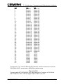
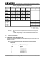
2.2.2.7 Digi I/O card and cables
This Digi I/O card (part number 667/7/22609/004, PCDIO48-P needs a half slot in
the PC; a full slot can be used if there are no half slots available.
The various blocks of jumpers on the board should be set as follows:
Jumper
JP1
JP2
JP3
JP4
JP5
Setting
The N/A jumper, only, should be bridged
No jumpers should be fitted
All Jumpers should be set to position B
All Jumpers should be set to position B
All Jumpers should be set to position B
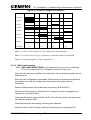
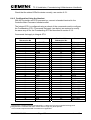
The address of the board(s) should be set using S1, the Base Address DIP switch,
as follows:
Board Number
1
2 (if required)
Address
320H
328H
The corresponding address switch settings are:
A9
OFF
OFF
A8
OFF
OFF
A7
ON
ON
A6
ON
ON
A5
OFF
OFF
A4
ON
ON
A3
ON
OFF
A2
ON
ON
Address
320H
328H
Board
1
2
The switch positions are labelled to indicate which switch corresponds to A2
through to A9. A label also indicates what position the switches should be in for
ON
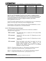
Two 50-way ribbon cables (part number 667/1/22629/000) are used to connect the
Digi I/O card to the PSU board in the ITU rack:
One cable is attached from the connector labelled J1 or P1 on the DIGI I/O Card to
connector PL4 on the PSU board, (the PSU board has a note on the silk screen
next to PL4 which reads 'CONNECTION TO P1 DIGI I/O (PC)'.
666/HE/43100/000
Page 15
Issue 10
TC12 Installation, Commissioning & Maintenance Handbook
The second cable is attached from the connector labelled J2 or P2 on the DIGI I/O
Card to connector PL3 on the PSU board, (the PSU board has a note on the silk
screen next to PL3 which reads 'CONNECTION TO P2 DIGI I/O (PC)'.
Note: The two 50-way ribbon cables are to be connected to the card before it is
installed into the PC.
WARNING
Please ensure cables are connected correctly, as they are not
polarised. After installation the cables should be labelled to show
which is connected to P1 and which is connected to P2.
2.2.2.8 IMD cards and cables
There are 3 different types of IMD cards and distribution unit which have been
used in TC12 Instations. Their differences and installation is described below:
2.2.2.8.1 DIGI PC/16i
The DIGI PC/16i comprises a full length ISA card (DIGI part number 50000160)
and an IMD Distribution Unit (labelled PC/16I I/O MATE INTERFACE). The PC
board has 3 jumpers (J1, J2 and J3) and 2 DIP switches (DS1 and DS2).
The 3 jumpers are used to set the local program memory size, which should be
64K. Each of the 3 jumpers has 3 pins which are numbered from top to bottom.
Each jumper should be set so that pins 2 and 3 are bridged.
Set the address of the dual-ported RAM to E0000 using DIP switch 1 (DS1)
positions 1 to 8, as shown below:
Address
E0000
D0000
A0000
SW1
ON
OFF
ON
SW2
OFF
ON
OFF
SW3
OFF
OFF
ON
SW4
OFF
OFF
OFF
SW5
ON
ON
ON
SW6
ON
ON
ON
SW7
ON
ON
ON
SW8
ON
ON
ON
[ON = PUSH SWITCH DOWN]
If, when the program is run, an address error is reported, the next available
address from the three listed above, should be tried.
If, more than one IMD board is installed in a TC12 PC, the address of the dualported RAM on each board be set the same.
666/HE/43100/000
Page 16
Issue 10
TC12 Installation, Commissioning & Maintenance Handbook
Set the I/O Port addresses of the boards using DIP switch 1 (DS1) positions 9 to
11, as shown below:
Board
1
2
3
4
SW9
ON
ON
OFF
ON
SW10
OFF
ON
OFF
OFF
SW11
OFF
OFF
ON
ON
Address
0x100
0x120
0x200
0x220
Set the interrupts using DIP switch 2 (DS2), positions 1 to 8, as shown below:
Board
1
2
3
4
SW1
OFF
OFF
OFF
OFF
SW2
OFF
OFF
OFF
OFF
SW3
ON
OFF
OFF
OFF
SW4
OFF
OFF
OFF
ON
SW5
OFF
OFF
OFF
OFF
SW6
OFF
ON
OFF
OFF
SW7
OFF
OFF
OFF
OFF
SW8
OFF
OFF
ON
OFF
Interrupt
IRQ5
IRQ11
IRQ15
IRQ7
2.2.2.8.2 DIGI AccelePort 16e
The DIGI PC/16i comprises a full length ISA card (DIGI part number 60000200)
and an IMD Distribution Unit (labelled Digi AccelePort 16e ISA DB25M RS232).
The PC board has a single jumper (J1) and 2 DIP switches (DS1 and DS2).
The jumper is used to set the local program memory size, which should be 64K.
The jumper has 3 pins which are numbered from left to right. The jumper should
be set so that pins 2 and 3 are bridged.
The setting of the2 DIP switches, DS1 and DS2, is the same as for the DIGI
PC/16i board (See 2.2.2.8.1).
2.2.2.8.3 DIGI AccelePort Xem
The DIGI AccelePort Xem comprises a three quarter length Xem ISA Host Adapter
(419/4/95931/000 - DIGI part number 77000211), a 16em DB25 Module
(653/4/05229/000 - DIGI part number 76000073) and a Xem 5ft Cable
(707/4/08514/000 - DIGI part number 62080060). Each 16em DB25 Module is
supplied with a short cable which enables a maximum of 4 16em DB25 Modules to
be daisy chained together. Two 16em DB25 Modules may be powered from the
ISA Host Adapter. Additional Modules require auxiliary power supplies
(605/4/08678/000 - DIGI part number 76000321).
The PC must be powered off before the Xem host adapter card is installed. The
PC should remain off until the 16em DB25 Modules have been connected to the
host adapter. The only set up required on the Xem host adapter is to set the I/O
port address to 124H-127H using DIP switch DS1
Address
124H-127H
666/HE/43100/000
SW1
OFF
SW2
ON
SW3
ON
Page 17
SW4
ON
Issue 10
TC12 Installation, Commissioning & Maintenance Handbook
2.2.2.9 IMD Distribution Modules (16i and 16e Units)
The IMD distribution Units (part number 667/7/22609/010), which are part of the
DIGI 16i and DIGI AccelePort 16e units are secured by clamps (667/2/22638/000)
to the IMD Distribution Mounting Panel (667/2/22636/000, see TC12 cabinet
assembly drawing 667/GA/22600/000 and TC12 IMD/Modem Panel assembly
drawing 667/GA/22635/000). This mounting panel is a hinged aluminium panel at
the back of the Instation. Each IMD Distribution Unit has two ribbon cables labelled
P2 and P3. The other end of these ribbon cables connects to the two connectors,
labelled P2 and P3, on the IMD card in the PC.
One IMD module contains 16 25-way D-type connectors. A group of four DConnectors connect via a single 24-way cable to one modem PCB, see section
2.2.4.2. This cable provides V.24 signals from the PC to the four modems on one
modem PCB.
The IMD Cables should be secured to the bottom of the hinged IMD panel.
Note: If it becomes necessary to replace either the IMD distribution box or the IMD
PCB they should both be changed at the same time.
Note: Before fitting the card into the PC, the card and the distribution unit should
be laid out on the bench and positions of the folds in the two ribbon
cables, determined. Where the ribbon cables pass through the rear of the
PC they should be strapped together with insulating tape. The card has to
be fitted to the PC before the ribbon cables are finally plugged into the
card.
2.2.2.10 IMD Distribution Modules (Xem Units)
The 16em DB25 Module is the wrong shape to be mounted on the hinged
aluminium panel and is normally mounted on a shelf within the TC12 cabinet. A
suitable shelf is a 1U Modem shelf (RS Part No 228-9441).
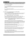
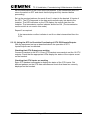
2.2.2.11 TC12 Instation PC Software Installation
The TC12 PC Software is supplied on a single floppy disk. There are 2 versions of
TC12 software currently in use, Version 7.4 should be used if it is required to
update an existing installation; Version 8.3 should be used on all new installations.
The installation procedure for both software versions is basically the same, but
version 8.3 has the following additional features:
•
•
•
•
Allows a PC processor card with onboard Ethernet to be used
An option to disable the playing of the start up tune
An option to disable the driving of the SIP.
The default screen display shows the state of the TCC Ethernet connection,
and the System and Operational alarm states.
If the TC12 PC does not have a built-in monitor, a VGA monitor should be
attached before starting the software installation process.
666/HE/43100/000
Page 18
Issue 10
TC12 Installation, Commissioning & Maintenance Handbook
The software installation procedure is as follows:
SAFETY NOTE
The PC should be plugged directly into the mains, and not via the mains
distribution panel on the Instation, since the Instation has not undergone on-site
safety tests, described in the commissioning section, at this stage.
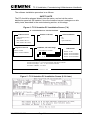
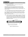
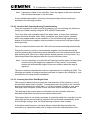
Figure 4 - TC12 Instation PC Installation Screen (7.4)
TC 12 INSTATION PC INSTALLATION
Ethernet Card
EtherLink II (3c503)
DEPCA
DEC Etherworks LC
DEC Etherworks Turbo
Digital I/O boards
Start Installation
Number of boards
No
Yes
Quit Installation
1
IMD-DS1, SW1-8 Settings
IMD boards
Use address 0 x E0000
Board #1 OK
Board #2 Not Installed
1
2
3
4
5
6
7
8 . .
.
Board
Board
Board
Board
#1 OK
#2 Not Installed
#2 Not Installed
#2 Not Installed
Use the cursor keys ↑ or ↓ to move between selections on menu
Use the cursor keys → or ← to move between menus
Use Enter or Return ↵ to select
Press Esc to exit
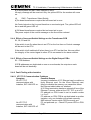
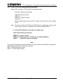
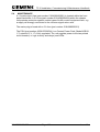
Figure 5 - TC12 Instation PC Installation Screen (8.3 & later)
666/HE/43100/000
Page 19
Issue 10
TC12 Installation, Commissioning & Maintenance Handbook
(1)
Before starting the TC12 software installation the Ethernet connection
should be configured using the instructions given in 2.2.2.5 or 2.2.2.6, as
appropriate.
(2)
Insert the TC12 Software disk into the PC and then switch the PC On. The
Installation software will auto-boot and 'SIEMENS' will be displayed for a
short time followed by the TC12 Instation PC Installation Screen, which
should look something like Figure 4 if the software is Version 7.4. If the
software is Version 8.3 it should something like Figure 5.
(3)
Check that the status for each IMD board is correctly indicated (see below
for possible display messages and actions).
If the Installation screen has locked up altogether and does not respond to
key presses check the Ram address switches are set up correctly on each
card (see section 2.2.2.8). If the switches are set correctly change to the
next available address as indicated in 2.2.2.8.1 and restart the installation.
(4)
Follow the instructions displayed for moving around the screen.
(5)
Select the type of Ethernet card that was installed in the PC from the
options on the 'Ethernet card' menu. (If an on-bard Ethernet connection is
being used, select the ‘Panel PC (UM9008)’ option.) On Version 7.4
software, move across to the 'Number of boards' menu and enter the
number of Ethernet cards that are installed in the PC - normally 1.
(6)
On version 8.3 Software, move to the ‘Tune’ menu and select YES or NO,
depending upon whether or not you wish the tune to be played when the
TC12 PC boots up. Move across to the 'SIP' menu and select YES if a SIP
is installed in the TC12 cabinet, otherwise select NO.
(7)
On Version 8.3 Software, move to the ‘Comms’ menu and select one of the
following options:
Modem
If a conventional leased line is being used to connect
the Instation to the OTUs.
Direct/Flow Control
If direct Instation to outstation, RS232,
communications are being used with CTS/RTS
flow control.
Direct/No Flow Cntrl
If direct Instation to outstation, RS232,
communications are being used without
CTS/RTS flow control.
(8)
Check the status of the DIGI I/O cards shown in the Digital I/O box.
Correctly installed cards will show as ‘OK’, cards which are not installed will
show as ‘Not installed’ and cards which are incorrectly installed will show an
error message which may give a clue as to the nature of the problem.
(9)
Check the status of the IMD cards shown in the IMD Cards box. Correctly
installed cards will be shown as ‘OK’ together with 2 numbers separated by
a ‘/’. The first number is the address of the board and the second number
the IRQ number of the board. Also shown will be the type of IMD board
which has been detected, either ‘Xi or Xe’ or ‘Xem’. Any boards which have
not been detected by the software will be shown as ‘Not detected’.
666/HE/43100/000
Page 20
Issue 10
TC12 Installation, Commissioning & Maintenance Handbook
(10) If the indications for the DIGI I/O and IMD cards are as expected, move
across to the 'Install' menu, select the 'Yes' option and hit return. The TC12
Software will now be installed on the Hard disk of the PC. Should the DIGI
I/O cards and/or IMD cards not be shown as expected then choose the
‘Quit’ option and correct the problem.
(11) Exit the Installation software. Eject the TC12 Software disk and keep this as
a backup.
(12) Disconnect the PC from the mains and disconnect the monitor. The PC can
now be installed in the TC12 cabinet.
2.2.2.11.1 Error Messages during TC12 Instation PC Software Installation
Messages and Errors that may be displayed on the 'Digital I/O boards' and 'IMD
boards' status menus during the software installation and suggested corrective
actions are shown below:
Displayed Message
OK
Not Installed
Ram Error
Faulty
Int. Failed
Action to be taken
None - Card installed OK
None unless card should be present; check card is inserted
correctly in PC slot, check switch settings of Port address
for IMD cards or address for Digi I/O cards (see section
2.2.2.7 or 2.2.2.8).
IMD cards only - check Ram address switches set up
correctly on card (see section 2.2.2.8).
Switches set correctly - change to next available address
as indicated in 2.2.2.8and restart installation.
Switches set incorrectly - correct and restart installation.
Replace card.
Check Interrupts set up correctly on the card (see2.2.2.8).
2.2.2.12 PC Mounting Chassis
The PC is accessible from the back of the Instation. It is placed on the PC
mounting chassis (667/2/22621/000), which is a shelf at the top of the Instation.
The PC is not visible from the front of the Instation as the System Fault Indication
Panel is fitted across the front. The PC mains lead plugs into a socket on the
Master switch Panel assembly at the back of the Instation.
Note: Lengths of 'U' channel (e.g. 915/4/03641/000) should be cut and placed
along the edges of the cut-outs in the back of the PC through which cables
pass, in order to eliminate the possibility of the cables chafing against the
edges.
If there is more than one IMD card in the PC, care should be taken to
avoid the possibility of the IMD cables chafing on the solder side of
adjacent PCBs. As far as is possible the IMD PCBs should be located
such that a spare slot exists between the IMD cables and adjacent PCBs.
666/HE/43100/000
Page 21
Issue 10
TC12 Installation, Commissioning & Maintenance Handbook
2.2.3 Systems Fault Indication Panel (SIP)
The SIP (part number 667/1/22667/000) is 6U high and is screwed to the Instation
racking in front of the PC.
If the Audible alarm on the system fault indication panel (SIP) sounds it should be
cancelled as required from the UTC TCC terminal. If the reason for the alarm is a
UTC TCC failure, an authorised/trained person (trained in the safety aspects of
working with mains powered equipment), should be asked to cancel the audio
alarm, using the audio off switch on the PSU PCB.
Under System Failure conditions the output relays for a remote SIP switch on and
off, which gives rise to a clicking sound. If the customer wishes to stop this sound
and there is no remote SIP fitted the following Resistor links may be removed from
the PSU board: R25, R41, R44, and R47. See 666/CF/02249/102 at the back of
the Handbook.
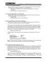
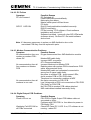
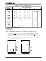
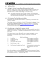
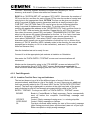
2.2.4 19" Racking PCBs
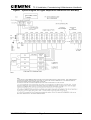
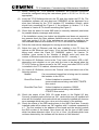
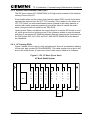
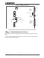
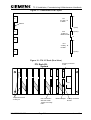
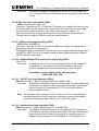
Figure 6 shows a front view of a fully equipped rack (there is an assembly drawing
for the rack, part number 667/GA/22626/000). The cards should only be put in the
slots in the order shown. A maximum of four racks may be fitted to an Instation.
Figure 6 - ITU 19" Rack (Front View)
6U Rack, Radial System
PSU
M
O
D
E
M
1
T
R
A
N
S
1
M
O
D
E
M
2
T
R
A
N
S
2
M
O
D
E
M
3
T
R
A
N
S
3
M
O
D
E
M
4
T
R
A
N
S
4
1.5”
666/HE/43100/000
Page 22
Issue 10
TC12 Installation, Commissioning & Maintenance Handbook
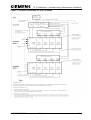
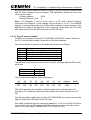
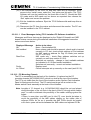
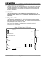
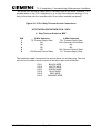
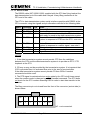
2.2.4.1 PSU PCB (inc. Digi I/O, SIP (local and remote), Watchdog and TC8 cables)
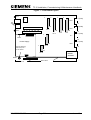
See Figure 7 for a diagram of the board layout showing the position of connectors,
LEDs, switches, volume control.
SAFETY NOTE
When installing the PSU PCB in the TC12 Instation cabinet the earth strap should
be bolted on to the PCB before the mains cable is plugged into the PCB. Similarly
when the PSU PCB is being removed, disconnect the mains plug from the mains
socket on the PCB, before removing the earth strap. Four earth straps are situated
on the right-hand 19" upright of the Instation cabinet, i.e. there is one strap
available at the correct height for up to four racks of TC12 that may be installed.
The earth strap comes with a bolt (+ star washer) and tag on one end which is
attached to the hole situated below the power supply on the PCB (see Figure 7 for
position of ground hole).
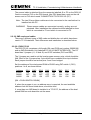
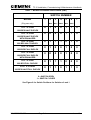
The switches on the PSU PCB should be set as follows:
(See Figure 8 for diagrams of switch settings)
S1 - PC Address
This should be set to '1'. If a second rack is fitted in the Instation then the position
of the switch, on the PSU Board in the second rack, does not matter. If there is
more than one PC connected to the same Ethernet link, the switch should be set
to 2 for the PSU Board connected to the second PC, 3 for the PSU Board
associated with the third PC, etc. The switch setting should correspond to the last
digit of the TC12 PC SCN in the associated UTC System’s database.
S2 - Audio Alarm Configuration Switch
This is a 4-way DIL switch. The usual setting for this switch is as follows:
switch position 1 should be closed
switches 2, 3 and 4 should be open.
The function of this switch is to enable certain inputs to the board, to cause the low
frequency alarm tone to sound.
Switch position
1
2
3
4
Input signal
Audio 1 Signal
Audio 2 Signal
Failure of PC
Failure of UTC TCC
Closing the appropriate switch causes the input signal indicated to cause a low
frequency alarm tone, should the signal become active. Note if more than one
switch is closed, any of the associated input signals becoming active, will cause
the alarm to sound.
The high frequency alarm tone is sounded if the Audio 2 Signal becomes active.
This is not configurable. It can only be disabled using the audio on/off switch (see
below).
666/HE/43100/000
Page 23
Issue 10
TC12 Installation, Commissioning & Maintenance Handbook
S3 - Audio ON/OFF
This switch should normally be set to on. If it is set off then LED LP2 will light once
the board is powered up and the local SIP audio alarm will not sound in the event
of any faults.
If the Audible alarm on the system fault indication panel (SIP) sounds it should be
cancelled as required from the UTC TCC terminal. If the reason for the alarm is a
UTC TCC failure, an authorised/trained person (trained in the safety aspects of
working with mains powered equipment), should be asked to cancel the audio
alarm, using the audio off switch on the PSU PCB.
Volume Control
The volume of the audio alarm is adjusted by turning the screw on potentiometer
RV1.
Connector PL1
Connect the cable (part number 667/1/22612/000) from the local SIP into
connector PL1 on the PSU PCB in the first rack. The PCB will need to be in the
card guide for the cable to reach. If there are additional 19" racks in the Instation
there is no connection to connector PL1 on the other PSU boards in these racks.
Connector PL2
Connector PL2 - No connection normally. This is used to connect to digital output
boards when used in a digital output rack (See section 2.2.5.2), as well as for
interfacing with the Telecommand 8 highway.
Connectors PL3 and PL4
Connectors PL3 and PL4 connect to the Digi I/O card as described in section
2.2.2.7.
Connectors PL5 to PL8
Connectors PL5 to PL8 connect to Modem PCBs as described in section 2.2.4.2.
Connector PL9
Connector PL9 - No connection normally (used for a remote SIP only).
Connector PL10 - Additional Racks In the Same Cabinet
If a further rack are included in the Instation then the PSU board on the second
rack is set up as follows
Connect from PL10 on the first PSU PCB to PL10 on the second PSU PCB, using
cable 667/1/22655/000. If a third rack is fitted, connect from PL10 on the second
PSU PCB to PL10 on the third PSU PCB and so on.
Connectors PL1, 2, 3, 4 and 9 are not used on the PSU PCBs of additional racks.
Connectors PL5 to PL8, on the PSU PCBs of additional racks, connect to modem
boards in those racks.
666/HE/43100/000
Page 24
Issue 10
TC12 Installation, Commissioning & Maintenance Handbook
Figure 7 - PSU Board Layout
LP1
1
1
1
1
1 (TOP)
S2
S1
PL5
14
S3
20
TP4 TP5 TP6 TP7 TP8 TP9
1 (TOP)
PL1
LP2
PL6
50
50
50
14
+12V +5V +5V GND AGND -12V
PL2
PL3
PL4
1 (TOP)
1
PL7
Variant
14
1 (TOP)
Power Supply
26
1
Hole for attaching
earth strap from
TC12 cabinet
PL8
PL9
14
10
PL10
MAINS
SOCKET
GND
Mains Wires
Ser. No.
666/HE/43100/000
Page 25
Issue 10
TC12 Installation, Commissioning & Maintenance Handbook
Figure 8 - PSU Board Switch Settings
666/HE/43100/000
Page 26
Issue 10
TC12 Installation, Commissioning & Maintenance Handbook
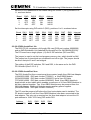
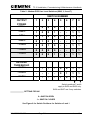
Setting the Voltage Range of the PSU
The Power supply fitted to every PSU board used in the system (part number
667/7/22631/000, manufactured by Daren Electronics PLC type PP40-30). An
internal link in this power supply needs to be set for the nominal mains voltage.
See Figure 9 for link setting; set to 110 V position for 98 V to 132 V mains voltage
range, set to 240 V for 198 V to 264 V mains voltage range.
Figure 9 - PSU Board Mains Voltage Range Setting
PSU
240V
110V
Mains
Connections
Low Voltage
Connections
1. Make sure that the PSU PCB is not plugged into the Mains Supply.
2. Disconnect the low voltage and Mains connectors from the PSU.
3. Remove the four screws that attach the PSU to the PCB.
4. Remove the cover from the PSU by removing a further four screws.
5. Set the Mains voltage link inside the PSU to the required position:
110 V or 240 V, as shown in Figure 9.
6. Replace the cover and screw the PSU back on to the PCB.
Ensure that the PCB is fitted the correct way around i.e. the Mains
connector and low voltage connector are at the correct ends of the PCB.
7. Re-connect the two PSU connectors
2.2.4.2 Modem PCB and Modem power cable
Figure 9 shows the position of the switches and connectors on the Modem PCB.
Ensure that the correct variant has been supplied e.g.
666/1/02243/000 for the UK.
666/1/02243/000 or 666/1/02243/001 for non-UK (the /001 variant includes extra
components; metal oxide varistors and gas discharge tubes, for surge protection).
The switches on the Modem PCB should be set as follows:
Note: The tables referred to below contain 0's to indicate open switches and 1's
to indicate closed switches. For all the switches push the switch down to
the left for a 0 and down to the right for a 1. The 0 and 1 position is shown
on the silkscreen underneath switch SW7.
666/HE/43100/000
Page 27
Issue 10
TC12 Installation, Commissioning & Maintenance Handbook
1. SW1 - Mode Select switch
Ensure that the Mode Select switch is set correctly; see Table 1 for
settings. One of the modes shown is selected on a 7-way DIL switch.
Note NO other settings are to be used in the UK.
2. SW2, SW3, SW6 and SW7 - Line Level switches
Ensure that the Line Level switches are set correctly see Table 2 for
settings). Table 2 shows switch settings corresponding to the different
levels. Each modem PCB contains four DIL switches. SW2 and SW3 are
8-way DIL switches, used for setting the line levels for modem 1 and 2
respectively. SW6 and SW7 are 6-way DIL switches used for setting the
line levels for modem 3 and 4.Positions 1 to 4 of all four switches set the
Output Power and positions 5 and 6 set the Receive Threshold. Position
7 and 8 on SW2 and SW3 are unused. Table 2 shows the setting for the
8-way DIL switches, ignore columns 7 and 8 for the 6-way switches.
For UK use the output power is always set to -13dBm and the receive
threshold is set to -39dBm.
Note: NO other setting except for -13dBm is to be used in the UK.
3. SW4 - 2/4 Wire Selector switch (SW4).
Ensure that the 2/4 Wire Selector switch is set correctly (see Table 3 for
settings).
4. SW5 - Transformer Select switch.
Ensure that the Transformer Select switch (SW5) is set correctly (see
Table 4 for settings). In a radial system (i.e. for any modem connecting to
a transformer board, the switch is set to off board transformers. For all
modems not connected to transformer boards, on board transformers are
selected.
The PCB is fitted with a cover (part number 667/2/22642/000 top, /001 rear). This
cover must ALWAYS be fitted before any connectors are attached to the PCB and
should NEVER be removed whilst any cables are connected to the PCB.
Each Modem PCB has a 14-way ribbon cable (part number 667/1/22643/000) and
a 24-way cable (part number 667/1/22640/000):
Connector PL2
The 14-way cable connects the middle header (PL2) on the Modem PCB to the
appropriate 14-way header on the PSU PCB, as follows:
Modem PCB 1 -> PL8 on the PSU PCB
Modem PCB 2 -> PL7 on the PSU PCB
Modem PCB 3 -> PL6 on the PSU PCB
Modem PCB 4 -> PL5 on the PSU PCB
666/HE/43100/000
Page 28
Issue 10
TC12 Installation, Commissioning & Maintenance Handbook
Connector PL1
The 24-way cable connects the top header (PL1) on the Modem PCB to four 25way 'D' connectors on the IMD distribution panel, as follows:
Modem PCB 1 ->
Modem PCB 2 ->
Modem PCB 3 ->
Modem PCB 4 ->
'D' connectors 1-4 on the distribution panel
'D' connectors 5-8 on the distribution panel
'D' connectors 9-12 on the distribution panel
'D' connectors 13-16 on the distribution panel
Note: Once installed the 24-way cables should be tagged with a number 1-4
corresponding to the modem PCB number for future identification.
The IMD distribution modules are positioned on the hinged panel with D-type
connectors 1, 5, 9 and 13 along the top row and D-types 4, 8, 12 and 16 along the
bottom row (the numbers are printed alongside the D-types on the IMD distribution
module). The ribbon cables from the IMD distribution modules therefore point back
towards the hinged side of the plate. The 24-way cable with four D-types (from a
modem PCB connections detailed above) can be cable tied along the bottom of
the hinged panel, with the D-type with the shortest wires (i.e. the D-type closest to
the berg connector at the other end) connected to the bottom D-type on the IMD
distribution panel, and the D-type with the longest wires connected to the D-type at
the top of the IMD distribution panel.
Connector PL3
Connector PL3 is used to connect to transformer boards in a system where
transformer boards are used (see section 2.2.4.3).
Connector PL3 connects via a special cable to directly to the MDF in a system
where transformer boards are not used (see Figure 14).
666/HE/43100/000
Page 29
Issue 10
TC12 Installation, Commissioning & Maintenance Handbook
Figure 10 - Modem PCB Layout
Mode
Select
S1
1 (TOP)
PL1
24 Way to
IMD panel
0 1
S2
Line
Level
S3
Line
Level
4 Wire
S4
Level
Off PCB ‘0’
S5
Level
S6
Line
Level
S7
Line
Level
24
Variant
PL2
14 Way to
PSU card
2/4 Wire 2 Wire
Selector
Level
Level
Transformer On PCB ‘1’
Select
Level
1 (TOP)
14
37
PL3
37 Way ‘D’
to MDF or
Transformer
PCB.
1 (TOP)
0 1
For switches SW1, SW2, SW3, SW3, SW5, SW6 and SW7 the switch is:
OPEN i.e. ‘0’ WHEN PUSHED DOWN TO THE LEFT, and
CLOSED i.e. ‘1’ WHEN PUSHED DOWN TO THE RIGHT
As a reminder the ‘0’ and ‘1’ positions are shown on the silkscreen below SW1 and
SW7.
For SW4, 4-wire is selected with the switch to the left and 2-wire is selected with the
switch to the right as shown above.
666/HE/43100/000
Page 30
Issue 10
TC12 Installation, Commissioning & Maintenance Handbook
Table 1 - Modem PCB Mode Select Switch (SW1)
SWITCH NUMBER
MODE
1
2
3
4
5
6
!MC0
!MC1
!MC2
!MC3
!MC4
0
1
0
0
1
1
0
0
0
0
0
1
1
0
0
1
1
1
0
1
0
0
1
0
0
1
0
0
0
0
0
0
1
0
0
0
1
1
1
0
0
0
0
1
1
0
1
1
0
(Eng use only)
CCITT V.23 M2
7
1200 BPS HALF DUPLEX
CCITT V.23 M2
1200 BPS HALF DUPLEX
WITH EQUALIZER
CCITT V.23 M1
600 BPS HALF DUPLEX
CCITT V.23 M2
1200 BPS FULL DUPLEX
CCITT V.23 M2
1200 BPS FULL DUPLEX
WITH EQUALIZER
CCITT V.23 M1
600 BPS FULL DUPLEX
CCITT V.21 ORIG
300 BPS HALF/FULL DUPLEX
0 = SWITCH OPEN
1 = SWITCH CLOSED
See Figure 8 for Switch Positions for Switches 0 and 1
666/HE/43100/000
Page 31
Issue 10
TC12 Installation, Commissioning & Maintenance Handbook
Table 2 - Modem PCB Line Level Switches (SW2, 3, 6 and 7)
SWITCH NUMBER
OUTPUT
1
2
3
4
5
6
7
8
POWER
0dBm
1
0
0
0
-
-
1
1
-3dBm
1
0
0
1
-
-
1
1
-6dBm
0
1
0
0
-
-
1
1
-9dBm
0
1
0
1
-
-
1
1
-10dBm
0
0
1
0
-
-
1
1
-13dBm
0
0
0
0
-
-
1
1
-16dBm
0
0
0
1
-
-
1
1
RECEIVE
THRESHOLD
-42dBm
-
-
-
-
0
0
1
1
-39dBm
-
-
-
-
0
1
1
1
-33dBm
-
-
-
-
1
0
1
1
↑
↑
Switch positions 7 and 8
apply to SW2 and SW3 only.
SW6 and SW7 are 6-way switches.
SETTING FOR UK
0 = SWITCH OPEN
1 = SWITCH CLOSED
See Figure 8 for Switch Positions for Switches 0 and 1
666/HE/43100/000
Page 32
Issue 10
TC12 Installation, Commissioning & Maintenance Handbook
Table 3 - Modem PCB 2/4 Wire Select Switch (SW4)
2 - Wire Operation
Switch 1 → 2 - Wire
Switch 2 → 2 - Wire
Switch 3 → 2 - Wire
Switch 4 → 2 - Wire
MODEM 1
MODEM 2
MODEM 3
MODEM 4
4 - Wire Operation
Switch 1 → 4 - Wire
Switch 2 → 4 - Wire
Switch 3 → 4 - Wire
Switch 4 → 4 - Wire
1
2
4 - WIRE
2 - WIRE
3
4
SW4
Table 4 - Modem PCB Transformer Select Switch (SW5)
Switch numbers (Corresponds to Modem with same number)
1
2
3
4
Set switch to 1 (Closed) to select on board
transformer for the Modem in question i.e. for
any Modem NOT connected to a transformer
board.
5
6
NOT USED
Set switch to 0 (Open) to select off board
transformers for the Modem in question i.e. for
any Modem connected to a transformer board.
See Figure 8 for Switch Positions for Switches 0 and 1
666/HE/43100/000
Page 33
Issue 10
TC12 Installation, Commissioning & Maintenance Handbook
2.2.4.3 Transformer PCB and Modem/Transformer Cable
Figure 10 shows the layout of the Transformer PCB.
Ensure that the correct variant has been supplied e.g.
666/1/02245/000 for the UK.
666/1/02245/000 or 666/1/02245/002 for non-UK.
The PCB is fitted with a cover (part number 667/2/22647/000 top, /001 rear). This
cover must ALWAYS be fitted before any connectors are attached to the PCB, and
should NEVER be removed whilst any cables are connected to the PCB.
Each Transformer PCB has a ribbon cable (part number 667/1/22646/000) with a
14-way connector at one end and a 37-way 'D' connector at the other. This
connects the Transformer PCB (T1, T2 etc.) to its associated Modem PCB (i.e.
M1, M2 etc.).
Transformer Board Connector PL2
The cable connects from PL2 on a transformer PCB to PL3 on its associated
modem PCB.
Figure 11 shows a rear view of a fully equipped rack. The positions of the ribbon
cables are indicated.
Transformer Board Connectors PL1 and PL3
These connectors are used for connection to the MDF (see Figure 15).
Transformer Board Switches S1, S2, S3 and S4
Ensure that for any unused telephone lines the corresponding switches on the
front of the PCB are set to ON. For example, if the 7th and 8th radial lines of
modem 2 are not used then switches 7 and 8 of S2 should be put to the on
position.
666/HE/43100/000
Page 34
Issue 10
TC12 Installation, Commissioning & Maintenance Handbook
Figure 11 - Transformer PCB Layout
37
S1
PL1
37 Way ‘D’
to MDF.
Variant
1 (TOP)
S2
PL2
14 Way to
Modem PCB
1 (TOP)
14
S3
37
PL3
37 Way ‘D’
to MDF.
S4
1 (TOP)
Figure 12 - ITU 19" Rack (Rear View)
ITU Rack 6U ,
System
24 Way connector
to PC
PSU
Telephone line I/F
37 way ‘D’.
666/HE/43100/000
IDC connectors
with IDC cable:
14way to 37 Way
PSU
Page 35
Modem Output 14 Way connector
to PSU
Issue 10
TC12 Installation, Commissioning & Maintenance Handbook
2.2.5 Digital Output Rack, PCBs and PSUs
The digital output rack is the same size as the ITU rack except that 17 card guides
are fitted. These take one PSU PCB and between 1 and 16 Digital Output PCBs.
The assembly drawing for the rack is 667/GA/22626/001. One or two racks may
be fitted to an Instation.
2.2.5.1 PSU PCB
The PSU PCB is identical to the ITU rack PSU PCB so see section 2.2.4.1 for
configuration details. Details of how to connect to the digital output rack are in the
next section.
2.2.5.2 Digital Output PCB
There are several variants of the PCB, /000 to /099 have current source outputs
and /100 to /199 have current sink outputs. The variants in those two groups are to
cope with different output current limit values.
See Figure 13 for a diagram of the board layout showing the position of
connectors, LEDs and switches.
Figure 13 - Digital Output PCB Layout
Variant No.
1 (TOP)
S1
PL1
LP1 POWER LED
40
LP1 WATCHDOG LED
1 (TOP)
14
PL4
PL2
1 (TOP)
50
FS1FS2
40
FS3FS4
1 (TOP)
PL3
1 (TOP)
666/HE/43100/000
PL5
Serial Number
Page 36
14
Issue 10
TC12 Installation, Commissioning & Maintenance Handbook
Switch S1 PCB Address
Set the switch on the card closest to the PSU PCB to 0, the next card to 1 and so
on up to F if 16 boards are fitted.
Connectors PL1 and PL2
These connectors are used to take the digital outputs out of the cabinet. Either a
ribbon cable kit (667/1/22742/000) or a discrete wire cable kit (667/1/22742/001)
are used to make up the cables on installation. The pin outs are as follows:
666/HE/43100/000
Page 37
Issue 10
TC12 Installation, Commissioning & Maintenance Handbook
Pin
1
2
3
4
5
6
7
8
9
10
11
12
13
14
15
16
17
18
19
20
21
22
23
24
25
26
27
28
29
30
31
32
33
34
35
36
37
38
39
40
PL1
Output 0
Output 1
Output 2
Output 3
Output 4
Output 5
Output 6
Output 7
Output 8
Output 9
Output 10
Output 11
Output 12
Output 13
Output 14
Output 15
Output 16
Output 17
Output 18
Output 19
Output 20
Output 21
Output 22
Output 23
Output 24
Output 25
Output 26
Output 27
Output 28
Output 29
Output 30
Output 31
XVCC
XVCC
XVCC
XVCC
XGND
XGND
XGND
XGND
PL2
Output 32
Output 33
Output 34
Output 35
Output 36
Output 37
Output 38
Output 39
Output 40
Output 41
Output 42
Output 43
Output 44
Output 45
Output 46
Output 47
Output 48
Output 49
Output 50
Output 51
Output 52
Output 53
Output 54
Output 55
Output 56
Output 57
Output 58
Output 59
Output 60
Output 61
Output 62
Output 63
XVCC
XVCC
XVCC
XVCC
XGND
XGND
XGND
XGND
Connect pins 1 to 32 to the LEDs on the wall map, and the common pin for those
32 LEDs to XVCC current sink or XGND for current source.
Connector PL3
Connect cable 667/1/22743/000, a 50 way cable with 17 sockets, to PL2 of the
PSU PCB and to PL3 of all the Digital Output PCBs in the rack.
666/HE/43100/000
Page 38
Issue 10
TC12 Installation, Commissioning & Maintenance Handbook
Connector PL4
Connect cable 667/1/22744/000, a 14 way cable with 17 sockets, to PL5 of the
PSU PCB and to PL4 of all the Digital Output PCBs in the rack.
Connector PL5
Connect cable 667/1/22717/000 to PL5. The other end wires into a terminal block
on the wall map PSU mounting panel, the other side of which connects to the DC
outputs of the power supply.
2.2.5.3 Wall Map PSU
Two Wall Map PSU mounting panels (667/1/22740/000 and /001) can be fitted to
the sides of the cabinet, giving a maximum of eight power supplies. Each can
supply 6 A at 24 V. There is a terminal block on each panel to connect the mains
to all the PSUs. Each Wall Map PSU (667/1/22741/000) contains another terminal
block and wires to enable wiring of low voltage power (for driving outputs) to PL5
of a number of Digital Output PCBs. The actual number of digital output PCBs will
depend on the amount of current each PCB is supplying to its outputs. See
667/CA/22741/000 and Figure 2 for wiring details.
2.2.6 PSTN Modem
If a PSTN modem (667/1/22662/000) is required this may be fitted to the back of
the hinged IMD distribution panel at the back of the Instation.
2.2.7 External Cables
2.2.7.1 Mains Cable
The mains cable to the Instation should be at least 15 Amp cable, and the plug
should be fitted with a fuse appropriate to the cable rating. The mains cable is
wired to the input of the master switch panel RCD; refer to drawing
667/GA/22603/000 for connection details.
2.2.7.2 Ethernet cable
The TC12 Ethernet Cabling must only be used to connect a UTC Traffic Control
Computer (TCC) to its associated TC12 PCs. No other equipment should be
connected to this, dedicated, TC12 Ethernet cabling.
There are three different situations for connection of the Ethernet.
(1)
System with a single PC using Thinwire Cable
Fit an Ethernet cable T piece (part number 667/7/22609/007) to the UTC TCC and
Ethernet card on the PC.
Fit an Ethernet cable terminator (part number 667/7/22609/008) to the T piece on
the UTC TCC and PC.
Fit the UTC TCC to PC Ethernet cable (part number 667/7/22609/006) between
the remaining connectors on the Ethernet cable T pieces at the UTC TCC and PC.
666/HE/43100/000
Page 39
Issue 10
TC12 Installation, Commissioning & Maintenance Handbook
(2)
System with multiple PCs using Thinwire Cable
Fit an Ethernet cable T piece (part number 667/7/22609/007) to the UTC TCC and
the Ethernet card on each PC.
Fit an Ethernet cable terminator (part number 667/7/22609/008) to the T piece on
the UTC TCC.
Fit the UTC TCC to PC Ethernet cable (part number 667/7/22609/006) between
the Ethernet cable T pieces at the UTC TCC and the first PC.
Fit PC to PC Ethernet cables (part number 667/7/22609/005) between the
Ethernet cable T pieces at the first and the second PC.
Fit PC to PC Ethernet cables (part number 667/7/22609/005) between the
Ethernet cable T pieces to link up any other PCs in the system.
Fit an Ethernet cable terminator (part number 667/7/22609/008) to the T piece on
the final PC.
(3)
System with single or multiple PCs using Twisted Pair Cabling
For a System which uses Twisted Pair (also known as CAT5) cabling an Ethernet
hub is normally used between the UTC Traffic Control Computer (TCC) and the
TC12 PC(s). CAT5 (Twisted Pair) cable is used to connect the TCC to the hub and
to connect the hub to the TC12 PC(s).
2.2.7.3 Modem PCB to BT cable
This cable is only fitted if there is no associated Transformer PCB with the Modem
PCB. Figure 14 shows the cable terminations for connection to the MDF.
The cable is a 10 pair cable (part number 667/1/22654/000) with 8 pairs actually
used. Refer to drawing 667/GA/22654/000 for wire colours etc. The cable
connects to PL3 on the modem PCB.
BT cable tool, part number 667/7/22648/000 is used when installing the cable.
Cable termination depends on whether the modem is connected in 2 or 4 wire
mode:
2 Wire Connection (Control and reply use same wire pair)
Modem 1
Control/Reply
TD1+
Modem 2
Control/Reply
TD2+
Modem 3
Control/Reply
TD3+
Modem 4
Control/Reply
TD4+
TD1TD2TD3TD4-
4 Wire Connection (Control and reply use separate wire pairs)
Modem 1
Control
TD1+ TD1Reply
RD1+ RD1Modem 2
Control
TD2+ TD2Reply
RD2+ RD2Modem 3
Control
TD3+ TD3Reply
RD3+ RD3Modem 4
Control
TD4+ TD4Control
RD4+ RD4-
666/HE/43100/000
Page 40
Issue 10
TC12 Installation, Commissioning & Maintenance Handbook
Figure 14 - Modem PCB - MDF Connections
MODEM PCB - PL3
PIN
1.
2.
3.
4.
5.
6.
7.
8.
9.
10.
11.
12.
13.
14.
15.
16.
17.
18.
19.
20.
21.
22.
23.
24.
25.
26.
27.
28.
29.
30.
31.
32.
33.
34.
35.
36.
37.
666/HE/43100/000
37 Way ‘D’ Connector
to transformer PCB or MDF
NAME
NOTES
TD1+
To MDF
RD1+
To MDF
TD2+
To MDF
RD2+
To MDF
TD3+
To MDF
RD3+
To MDF
TD4+
To MDF
RD4+
To MDF
NC
NC
NC
NC
NC
RTN4
To Transformer PCB
NC
MD3
To Transformer PCB
RTN2
To Transformer PCB
NC
MD1
To Transformer PCB
TD1To MDF
RD1To MDF
TD2To MDF
RD2To MDF
TD3To MDF
RD3To MDF
TD4To MDF
RD4To MDF
NC
NC
NC
NC
NC
MD4
To Transformer PCB
RTN3
To Transformer PCB
NC
MD2
To Transformer PCB
RTN1
To Transformer PCB
Page 41
Issue 10
TC12 Installation, Commissioning & Maintenance Handbook
2.2.7.4 Transformer PCB to BT cable
Figure 14 shows the cable terminations for connection to the MDF.
Two identical cables are used (part number 667/1/22654/001). These connect to
PL1 and PL3 on the appropriate Transformer PCB. The cable connected to PL1
connects all the OTUs associated with modems 1 and 2. The cable connected to
PL3 connects all the OTUs associated with modems 3 and 4. Each of the two
cables is a 20 pair cable with up to 16 pairs actually used. Refer to drawing
667/GA/22654/001 for wire colours etc.
If only one modem (of the four available on a modem PCB) is being used then a
10 pair cable can be used, part number 667/1/22654/000. Refer to drawing
667/GA/22654/000 for wire colours associated with particular connector pins.
If the 10 pair cable is used then the following two connections are possible:
1) 10 Pair cable connected to PL1:
Modem 2 only used with pair
TP9 of 10 pair cable to OTU 2A
TP8 of 10 pair cable to OTU 2B
TP7 of 10 pair cable to OTU 2C
TP6 of 10 pair cable to OTU 2D
TP5 of 10 pair cable to OTU 2E
TP4 of 10 pair cable to OTU 2F
TP3 of 10 pair cable to OTU 2G
TP2 of 10 pair cable to OTU 2H
2) 10 Pair cable connected to PL3:
Modem 4 only used with pair
TP9 of 10 pair cable to OTU 4A
TP8 of 10 pair cable to OTU 4B
TP7 of 10 pair cable to OTU 4C
TP6 of 10 pair cable to OTU 4D
TP5 of 10 pair cable to OTU 4E
TP4 of 10 pair cable to OTU 4F
TP3 of 10 pair cable to OTU 4G
TP2 of 10 pair cable to OTU 4H
BT cable tool, part number 667/7/22648/000 is used when installing the cable.
666/HE/43100/000
Page 42
Issue 10
TC12 Installation, Commissioning & Maintenance Handbook
Figure 15 - Transformer PCB - MDF Connections
TRANSFORMER PCB PL1 and PL3
PIN
1.
2.
3.
4.
5.
6.
7.
8.
9.
10.
11.
12.
13.
14.
15.
16.
17.
18.
19.
20.
21.
22.
23.
24.
25.
26.
27.
28.
29.
30.
31.
32.
33.
34.
35.
36.
37.
666/HE/43100/000
37 Way ‘D’ Connector to MDF
PL1 NAME
PL3 NAME
NC
NC
OTU2HOTU4HOTU2GOTU4GOTU2FOTU4FOTU2EOTU4EOTU2DOTU4DOTU2COTU4COTU2BOTU4BOTU2AOTU4AOTU1HOTU3HOTU1GOTU3GOTU1FOTU3FOTU1EOTU3EOTU1DOTU3DOTU1COTU3COTU1BOTU3BOTU1AOTU3ANC
NC
NC
NC
NC
NC
OTU2H+
OTU4H+
OTU2G+
OTU4G+
OTU2F+
OTU4F+
OTU2E+
OTU4E+
OTU2D+
OTU4D+
OTU2C+
OTU4C+
OTU2B+
OTU4B+
OTU2A+
OTU4A+
OTU1H+
OTU3H+
OTU1G+
OTU3G+
OTU1F+
OTU3F+
OTU1E+
OTU3E+
OTU1D+
OTU3D+
OTU1C+
OTU3C+
OTU1B+
OTU3B+
OTU1A+
OTU3A+
NC
NC
Page 43
Issue 10
TC12 Installation, Commissioning & Maintenance Handbook
2.3
COMMISSIONING
2.3.1 Safety Tests on the TC12 Instation
2.3.1.1 Test Equipment Required
Multimeter (e.g. Fluke 77 or similar).
Comark Insulation Meter 1905 (or similar capable of 1000 V).
Clare R133R10 Earth Continuity Tester (or similar).
RCD Tester (e.g. Seaward RC500).
2.3.1.2 Safety Considerations
Statutory and Company legislation relating to safety must be followed. During
testing hazardous voltages will be present, only qualified personnel are allowed to
operate the equipment with hazardous voltages present.
ELECTRIC SHOCK RISK - hazardous voltages are present within the equipment observe any warning labels and do not remove any protective covers.
2.3.1.3 Pre-test Inspection
Check that the correct fuses are fitted to the Instation (see section 2.4.9 for a
description of fuses fitted to the Instation). Carry out a visual inspection to check
all earth connections are made and that the associated screws are done up firmly.
Check that the mains cables are plugged into each PSU PCB and PC used.
2.3.1.4 Outline of Tests to be Performed
The sequence of tests will be:
(1)
(2)
(3)
Earth Continuity Check
Insulation Check (1000 V DC Test)
RCD Test.
2.3.1.5 Earth Continuity/Insulation Resistance Test Set Up
The Instation is disconnected from the mains during these tests.
2.3.1.6 Earth Continuity Test Procedure
Connect one probe of the Earth Continuity Tester to the Earth wire of the Instation
mains cable. Connect the other probe to the following points (it may be necessary
to find a suitable place to test without paint) and make sure the reading is below
0.5 Ohms:
Cabinet Uprights
666/HE/43100/000
Page 44
Issue 10
TC12 Installation, Commissioning & Maintenance Handbook
Cabinet Side Cover stud left hand side
Cabinet Side Cover stud right hand side
Cabinet Top Cover
Cabinet rear door
Metal Part of front door along hinged side
SIP Panel
IMD Panel
Master Switch Panel at the rear of the cabinet
Master Switch panel cover (aluminium plate behind the master switch panel).
Mains socket panel at the front of the cabinet
Any installed 19" racks - both left and right mounting flanges should be checked
PC Mounting metalwork
Case of power supply on every PSU Board Installed.
Volt rail on the PSU PCB of every TC12 rack installed in the cabinet The 0 Volt rail
is accessible at terminal pin TP7 on the PSU PCB, see Figure 7 for position of this
terminal pin on the PCB.
All earthed points on any other equipment which may have been included in the
cabinet.
If after the on site earth continuity test, any rack or panel is removed or replaced,
then the earth continuity check to that item should be repeated.
2.3.1.7 Insulation Resistance Test Procedure
SAFETY NOTE
Personnel should take care that they do not come into contact with the high
voltages generated by the Test Instrument.
Set the insulation meter to 1000 V DC.
Make Sure that the Instation is not connected to the mains, but that all fuses are in
place, all switches are on (i.e. master Switch and Switches for front and rear mains
socket panels) and that all PCBs etc. are in place.
Connect the LIVE and NEUTRAL of the Instation mains wire together.
Connect the meter to measure between the Instation mains wire EARTH and the
combined LIVE and NEUTRAL.
Allow the meter reading to settle during the test.
The insulation resistance should be not less than 10 MOhm.
Note Once the Instation has passed the Insulation resistance test it should not
be repeated unnecessarily as the mains filters may be damaged.
WARNING Mains filters may remain charged for some time after the insulation
tests have been completed.
666/HE/43100/000
Page 45
Issue 10
TC12 Installation, Commissioning & Maintenance Handbook
2.3.1.8 RCD Tests
Turn the Instation master Switch OFF.
Connect the Instation to the mains.
Switch the Instation master Switch ON.
Plug the RCD Tester into a mains socket at the front of the Instation. Set the trip
current on the tester to 30 mA. Press the button on the tester. Check on the RCD
tester display that the RCD has tripped within 200 ms. Reset the RCD.
Set the trip current on the tester to 150 mA. Press the button on the tester. Check
on the RCD tester display that the RCD has tripped within 40 ms.
Disconnect the tester from the controller and reset the RCD.
2.3.1.9 Safety of Mains Supply at Customer Site
The customer is to ensure that the mains supply that the Instation is to be
plugged into meets the requirements of IEE Wiring Regulations (BS7671).
2.3.2 Commissioning Procedure after Power Up
Switch on and check all power LEDs on the PSU and Modem PCBs are lit.
Check that the transmit LEDs (green) and receive LEDs (yellow) on the modem
PCBs illuminate correctly - see section 2.4.1.
666/HE/43100/000
Page 46
Issue 10
TC12 Installation, Commissioning & Maintenance Handbook
2.4
MAINTENANCE
2.4.1 Status LEDs
LEDs are provided on the front edge of the Modem Board and PSU Board to
provide basic status information. The position of these LEDs and their functions
are shown in Figure 16.
Modem PCB
All power LEDs on the modem PCB should be ON.
The yellow transmit LEDs indicate that the particular modem has received a
request to send. In normal working this means that the control signal is being
transmitted on the line. However if switches/cables have been set up incorrectly
the LED may be ON, without the control signal actually reaching the line. All yellow
LEDs on all modem PCBs should go on together (though not necessarily go off at
the same time) once per second.
The green receive LED (Carrier detect) should come on once for every OTU which
replies on the line during the second (the LED is set by the modem carrier detect
output and does not indicate that the carrier detected was a valid reply message).
PSU PCB
The PC power LED on the PSU PCB should be ON. IF it is OFF then there is a
fault, however no audible alarms will sound and no LEDs will illuminate on SIP
panel if the PC has no power.
Digital Output PCB
The Digital output PCB has two status LEDs. The top LED indicates that the
Power to the board is OK (5 V supply from PSU PCB).
The second LED on the digital output PCB indicates a watchdog fail. If this occurs
all digital outputs are switched off on that board.
666/HE/43100/000
Page 47
Issue 10
TC12 Installation, Commissioning & Maintenance Handbook
Figure 16 - Modem and PSU PCB Status LEDs
MODEM BOARD STATUS LEDs
LP1 (RED LED) - +12v
LP2 (RED LED) - -12v
LP3 (RED LED) - +5v
LP4 (YELLOW LED) - MODEM 1 TRANSMIT (TX1)
LP5 (GREEN LED) - MODEM 1 RECEIVE (RX1)
LP6 (YELLOW LED) - MODEM 2 TRANSMIT (TX2)
LP7 (GREEN LED) - MODEM 2 RECEIVE (RX2)
LP8 (YELLOW LED) - MODEM 3 TRANSMIT (TX3)
LP9 (GREEN LED) - MODEM 3 RECEIVE (RX3)
LP10 (YELLOW LED) - MODEM 4 TRANSMIT (TX4)
LP11 (GREEN LED) - MODEM 4 RECEIVE (RX4)
PSU BOARD STATUS LEDs
PC POWER
AUDIO OFF
2.4.2 Effect of Incorrect Switch Settings on the PSU PCB
(1)
S1 - PC Address
If this switch is set to a PC number which does not exist, the UTC TCC FAIL
indicator on the local SIP will light up. The traffic control computer will display an
error message to say that the PC is disconnected.
(2)
S2 - Audio Alarm Configuration Switch
666/HE/43100/000
Page 48
Issue 10
TC12 Installation, Commissioning & Maintenance Handbook
This controls what signals can cause the low frequency audio alarm to sound. If it
is incorrectly set, the alarm may sound for reasons other than those expected or
may not sound when expected.
(3)
S3 - Audio ON/OFF
If the audio alarm does not sound when expected check that this switch is set
correctly. If it is set to off the audio off LED, on the front of the PCB, will be
illuminated.
(4)
Alarm Volume Control (RV1)
If the Audio alarm volume control is set too low it may not be possible to hear the
audio alarm.
2.4.3 Effect of Incorrect Switch Settings on the Modem PCB
(1)
SW1 - Mode Select Switch
If this is set incorrectly the four modems on the modem PCB may not work at all or
will be set to a spurious mode. The yellow LED (request to send) may light for
each modem, but the green LED (carrier detect) may not.
(2)
SW2, SW3, SW6 and SW7 - Line Level Switches
SW2 and SW3 are 8-way switches used to set line levels for modem 1 and
modem 2 on the Modem PCB. If switch positions 1 to 4, of the DIL switch, are set
incorrectly the particular modem will transmit at the wrong output power.
WARNING - FOR UK USAGE THE OUTPUT POWER MUST NOT BE SET TO
GREATER THAN –13 dBm.
If switch positions 5 and 6 are set incorrectly the receive threshold for the
particular modem will be wrong. If it is set too low, corrupted reply messages may
occur, in which case reply too early errors may be displayed on the TCC. If set too
high the reply messages from the OTUs may be undetected - the yellow LED will
light for the appropriate modem but the green LED will not.
If Switch position 7 is set open, there will be no Control Signal on the line. The
yellow LED will light but the green LED will not light.
If Switch position 8 is set open, there will be no Reply Signal on the line. The
yellow LED will light but the green LED will not light.
SW6 and SW7 are 6-way DIL switches used to set line levels for modem 3 and
modem 4 on the Modem PCB. Incorrect setting of these switches will have the
same effect on these modems, as switch positions 1 to 6 described above.
(3)
SW4 - 2/4 Wire Selector Switch
a) 4 wire system but with 2 wire selected in error:
No reply messages will be received. In Full duplex mode the yellow and green
LED for the modem will come on simultaneously every second. In half duplex
mode only the yellow LED will come on.
666/HE/43100/000
Page 49
Issue 10
TC12 Installation, Commissioning & Maintenance Handbook
b) 2 wire system but with 4 wire selected in error:
No reply message will be received. Only the yellow LED for the modem will come
on.
(4)
SW5 - Transformer Select Switch
a) On board transformers required but off board set in error.
No Control signal on the line and therefore no received signal. The yellow LED will
be on and the green LED off.
b) Off board transformers required but on board set in error.
The power output of the control message on the line will be reduced.
2.4.4 Effect of Incorrect Switch Settings on the Transformer PCB
S1, S2, S3 and S4:
If the switch is set On when there is an OTU on the line then no Control message
will be sent to the OTU.
If the switch is left switched off when there is no OTU on that line, this may affect
the integrity of the control signal to other OTUs connected to the same modem.
2.4.5 Effect of Incorrect Switch Settings on the Digital Output PCBs
S1 - PCB Address
If PCB addresses are duplicated on one or more boards, the outputs on each
board will be set identically.
2.4.6 Fault Finding at the Instation
2.4.6.1 UTC TCC Communication Problems
Symptom
Possible Reason
No UTC TCC
Incorrect installation of PC Ethernet card or cables or
communications with
faulty Ethernet card. On the 3Com Ethernet card,
Instation, SIP VAX LED on. failure to disable the memory can cause this failure.
No Ethernet cable/cable not attached.
A 50 Ohm termination has been missed off one of the
Ethernet T-pieces, either at the UTC TCC or at a PC.
PC address on PSU board is set to invalid number
i.e. 0 or F.
PC address on PSU PCB is set duplicated in another
Instation; only one Instation will operate correctly.
IMD Interrupt Vector switch DS2 incorrectly set.
No UTC TCC
PC not powered up - Check PC power LED on PSU
communication with
PCB.
Instation, SIP VAX LED off
666/HE/43100/000
Page 50
Issue 10
TC12 Installation, Commissioning & Maintenance Handbook
2.4.6.2 PC Failure
Symptom
PC not Powered
SIP PC 1 LED ON
Possible Reason
PC Switched off.
Power cable disconnected/faulty.
Mains plug fuse blown
Master switch panel off/fuse blown.
PC faulty.
Digi I/O card card/cables installed incorrectly.
Digi I/O card faulty.
PC Not running TC12 software. Check software
installation and re-boot PC.
Software has failed - ignore all other SIP LEDs/audio
(software driven). Re-boot PC. Re-install software
and re-boot.
Note. If it becomes necessary to replace an IMD distribution box or the
associated PCB they must be replaced in pairs.
2.4.6.3 Modem Communication Problems
Symptom
Possible Reason
No communication from one D-type disconnected from IMD distribution module
modem on modem PCB others OK
Modem/IMD cable faulty
Incorrect MDF connection
OTU Disconnected/faulty
No communication from all
Incorrect Mode set on Modem PCB.
four modems on Modem
Radial system with modem PCB to transformer PCB
PCB
cable, disconnected/ faulty
Modem/IMD cable not connected/ connected to
wrong four D-types/ cable faulty
No power to modem PCB - check power LEDs,
check modem PCB to PSU PCB cable
Telephone line connection problem at MDF
No communication from all
No mains connection to PSU PCB
modems in one rack
Low Voltage side of PSU not connected on PSU PCB
PSU faulty on PSU PCB
No PSU PCB to modem PCB cables attached
IMD card/cables installed incorrectly/ faulty
2.4.6.4 Digital Output PCB Problems
Symptom
Possible Reason
Power LED not on
PSU PCB to Digital Output PCB ribbon cable not
connected or faulty.
Problems with PSU PCB i.e. fuse blown/no power to
PSU/faulty PSU
Watchdog Fail LED ON for
Check SIP Panel PC 1 LED. If on, PC software is not
all PCBs connected
running - reboot PC
666/HE/43100/000
Page 51
Issue 10
TC12 Installation, Commissioning & Maintenance Handbook
Symptom
Watchdog Fail LED ON for
only one
Digital Output PCB of
several
Digital Outputs Not Driven
Possible Reason
PSU to Digital Output PCB watchdog ribbon cable
faulty/not connected
Watchdog ribbon cable faulty
Digital Output PCB faulty
Watchdog Failure
Digital Output PCB fuse(s) blown
Incorrect/faulty wiring
Digital Output PSU not connected
Digital Output PSU fuse blown/faulty
2.4.7 Replacing Modem, Transformer and Digital Output PCBs
The modem and transformer and Digital Output PCBs can be removed and
replaced whilst the rack is powered up. Disconnect the attached cables from the
PCB, push down the latch on the front of the PCB guide and slide the PCB out of
the rack. Insert the new PCB and reconnect.
2.4.8 TC12 Instation PC Help / Diagnostic Screens
If a monitor is attached to the TC12 PC (note the TC12 Instation Test Set can be
used as the monitor) a number of Help/Diagnostic screens are available in the
TC12 PC Software. These are described below.
2.4.8.1 Help screen, Key to Press 'H'
This Screen lists all of the diagnostic and help screens and keys to be pressed to
activate them.
2.4.8.2 First 22 TC12 OTUs on an Instation, Key to Press '2'
This screen displays the replies received from the first 22 TC12 OTUs on an
Instation. It displays each OTU’s reply on a separate line on the screen, OTU 0 at
top. This screen only shows the first 22 OTUs on an Instation but can be used to
obtain indication of the health of the system.
The first eight digits on a line are characters indicating what errors were detected
with the particular OTU reply. The characters represent the errors as follows.
A = Address error
M = MT (message transfer) bit set in reply
N = No reply
S = Short reply
C = reply CRC error
P = parity error (not used in TC12)
F = framing error in reply
O = over run error on reply message
666/HE/43100/000
Page 52
Issue 10
TC12 Installation, Commissioning & Maintenance Handbook
The remaining characters on each line are the hexadecimal representation of the
reply bytes (__ means no data) for that OTU, each line is the correct length
(number of characters) for the number of reply bytes for the OTU.
2.4.8.3 First 22 TC8 OTUs on an Instation, Key to Press '8'
This screen displays the replies received from the first 22 TC8 OTUs on an
Instation. It displays each OTUs reply on a separate line on the screen OTU 0 at
top. The format of each line is as for TC12 above.
This screen only shows the first 22 OTUs on an Instation but can be used to obtain
an indication of the health of the system.
666/HE/43100/000
Page 53
Issue 10
TC12 Installation, Commissioning & Maintenance Handbook
2.4.8.4 Active tasks, RX/TX packets and time events, Key to Press 'A'
This screen, as its name suggests, shows the processes going on within the
Instation against time, each dot represents 400ths of a second and the screen
shows processes in any one second. For its full understanding a good working
knowledge of the Instation is required, however it is possible to see if one
particular task or time event is running more often than is normal or using up more
time than normal.
The graphical representation noted below are described as if viewing a
monochrome screen, however notes are made alongside to state what the colour
would be if a colour display were employed.
Meanings of the graphics
A dot . is a single 400th of a second time period
Inverse video blocks (brown) Indicate time events during which for example data is
output to TC8 OTUs. Digit above indicates time spent on event, should not
normally go above 5.
Indicates a packet received from the host UTC TCC via
the Ethernet, usually on bottom line of those displayed
and right hand corner.
It should be within the following bounds
It can be in yellow area
It should be in the red or green area as shown below
If it goes into the blue area it will be rejected and not acted upon.
17 dots
3rd line .................| Start of yellow area........
8 dots 8 dots 10 dots
4th line ...continuation of yellow area |........|........|.......... end of 4th line
RED | GREEN BLUE.
Indicates a packet transmitted to the host UTC TCC
normally on top line of display
Characters 0 to C indicates task with the following significance
C=
B=
A=
9=
8=
1 second timer update task, not normally visible.
High priority message received from the host UTC TCC ready for
output
Input from IMD usually reply data and process ready to transmit as
a packet back to host UTC TCC.
Message ready received across Ethernet from host/UTC TCC.
This is then distributed as necessary to High and Low priority
message tasks and configuration message task.
Not Used
666/HE/43100/000
Page 54
Issue 10
TC12 Installation, Commissioning & Maintenance Handbook
7=
Low priority message ready from UTC TCC to output e.g. digital
outputs
6=
Replies to a particular host UTC TCC where the Instation is only
handling digital Output for the particular host UTC TCC, with delays
on answering to maintain communication timings.
5=
Configuration processing i.e. processing of configuration packets
from host UTC TCC to setup Instation.
4=
Sumchecking IMDs done at beginning of every second (top left
hand corner of display. To ensure IMDs have correct timings and
data before allowing them to proceed with their transmission of
data to the modem boards and ultimately the OTUs.
3=
Discarding memory, this task is passed memory by the other task
for it to discard.
2=
processing for the Keyboard and Instation VDU i.e. standard
monitor if connected not emulated monitor.
1=
Serial processing including emulated monitor.
0=
Lowest task Instation initialisation.
2.4.8.5 Internal Error Counts, Key to Press 'B'
This screens shows counts of memory allocation errors associated with the
allocation of memory into which a packet received from the host UTC TCC is
placed and memory in which a packet is built prior to transmission back to the host
UTC TCC.
Rx packet allocation failures
Packet buffer allocation failure
These should never be other than zero 0.
2.4.8.6 Computer Links, Key to Press 'C'
Decnet Address = Address of the Instation PC on the Ethernet.
Timeout_count (usually 3) = Number of consecutive missing messages before
PC times out and ignores Ethernet link.
Sip_output = Indicates last states of 8 outputs which are sent to the Systems
Indication Panel, 1 = On.
Sip_Flash = Indicates which outputs were required to be flashing when last
sent to the Systems Indication Panel, 1 = Flash.
Sip_input_last_sent = States of 8 input available from Systems Indication panel
when last checked.
666/HE/43100/000
Page 55
Issue 10
TC12 Installation, Commissioning & Maintenance Handbook
2.4.8.7 Digital Outputs states, Key to Press 'D'
This screen displays the output states, of the first 24 TC12 digital output boards;
each line represents 64 digital outputs i.e. one board. As there is the possibility of
16 boards in a rack the first 16 lines therefore would represent first rack.
This display is in colour and CTERM should be switched into the colour mode to
gain any information from this screen Press CNTRL K.
The colours used are as follows and correspond to shades as detailed below for
the monochrome screen used on the test set.
Colour
Shade
Meaning
Blue
Red
White
Lightest
Medium
Darkest
Not used
In use for driving TC8
Actual states of inputs when in use.
NB
If only two shades can be seen it may be possible to distinguish what is
being shown in the following ways.
If 'O' is pressed the screen will be blank if there is NO TC8, if TC8 is being driven
screen will show data. With this knowledge above screen can be interpreted as
TC8 Outputs are always the first shown on the above screen i.e. top lines.
2.4.8.8 Event flags, Key to Press 'E'
This screen and the flags are self descriptive, however on the terminal emulator
the line showing the state of the flags cannot be viewed and this screen is
therefore of no use under normal circumstances.
2.4.8.9 Free time, Key to Press 'F'
This screen shows the current, worst, best and average free time as percentages.
NB After re-booting the Instation PC worst percent free time goes to 0%, as during
initialisation it is allowed to use all time available for processing. To determine the
worst percentage free time during normal operation reset counters once operating
normally by pressing 'Z'. The worst percentage free after five minutes should be an
accurate figure for the system.
2.4.8.10 Help Screen, Key to Press 'H'
This screen lists all of the screens detailed in this section.
666/HE/43100/000
Page 56
Issue 10
TC12 Installation, Commissioning & Maintenance Handbook
2.4.8.11 IMD Information Screen, Key to Press 'I'
This provides information about the Intelligent Modem Driver boards in the PC as
follows.
Top Line: Address of the dual ported RAM through which the PC communicates
with the IMDs.
Below this there are details of each of the four possible IMDs, as follows.
Status of the IMD:
Either OK / NOT INSTALLED / FAULTY / SUM CHECK ERROR.
Followed by a series of digits. These series of digits for each IMD relate to the
states of certain MODEM lines as defined below.
Current
Raised RTS and did not 0000000000000000
receive CTS
Started transmitting and
0000000000000000
lost CTS before completed
666/HE/43100/000
Page 57
Cumulative
0000000000000000
0000000000000000
Issue 10
TC12 Installation, Commissioning & Maintenance Handbook
2.4.8.12 Link Statistics, Key to Press 'L'
This screen gives details of the Ethernet link to the host UTC TCC.
The addresses of the Instation on the
Ethernet
The type of driver card being used Thin wire, Thick wire or both as detected
by the driver software
Type of Ethernet card selected when
installation programme used
The type of communication being used
NB The count increments against the
form of communication being used.
Whether or not adapter card has failed.
This is '1' if failed
Count indicating number of times the
status / set up of the link driver has
changed
Details on bad packets from Ethernet
Count of packets that were too short
(since starting PC)
Count of packets with wrong protocol
(since starting PC)
Count of packets which had invalid
destination address i.e. were not
intended to be picked up by this
Instation PC (since starting PC)
Bad Packet Protocol
Bad Packet Source
Bad Packet Destination
ADDRESS and
MULTICAST ADDRESS
MODULE TYPE
ADAPTER CARD
RECEIVE LOOK AHEAD or
RECEIVE CHAIN
ADAPTER CHECK
STATUS INDICATION
TOO SHORT
WRONG PROTOCOL
INVALID DESTINATION
Protocol number of last bad
packet
Source address of last bad
packet
Destination address for last
bad packet
2.4.8.13 Free memory, Key to Press 'M'
This gives an indication in Kbytes of the memory free within the PC that the
software could make use of.
2.4.8.14 Telecommand 8 Output, Key to Press 'O'
This screen shows any data being Output (2 words allowed for each OTU) to the
first 88 Telecommand 8 OTUs if there are any connected to the instation. If there
are no TC8 OTUs connected to the Instation this screen is blank.
666/HE/43100/000
Page 58
Issue 10
TC12 Installation, Commissioning & Maintenance Handbook
2.4.8.15 Received Characters IMD, Key to Press 'R'
This screen displays the data received from OTUs on IMD 0 port 0. It displays
each OTUs reply on a separate line on the screen OTU 0 at top. This screen only
shows the OTUs on IMD 0 port 0 but can be used to obtain indication of the health
of the system.
The characters on each line are the hexadecimal representation of the reply bytes
(__ means no data) for that OTU, each line is the correct length (number of
characters) for the number of reply bytes for the OTU.
2.4.8.16 Test Characters, Key to Press 'T'
Displays a set of characters to test the modes of the display. Not of any real use in
maintenance of the Instation, as in normal use the Instation has no display.
2.4.8.17 Reset Free time counters and IMD status indicators, Key to Press 'Z'
Simply resets counters to best condition i.e. 100% free, and IMD cumulative status
indicators to 0.
2.4.8.18 Exit
This text shows the combination of keys to press to exit the TC12 software on the
PC and return to DOS.
2.4.9 Fuses
Internal Power Supply Fuse on the PSU PCBs
The Power supply fitted to every PSU board used in the system (part number
667/7/22631/000, manufactured by Daren Electronics PLC type PP40-30) is fitted
with an Anti surge 1 A, 250 V 20 x 5 mm fuse (part number 518/4/90631/015).
Master Switch Panel Assembly
Figure 16 shows the layout of the Master Switch Panel and RCD. The positions of
the fuses are shown.
666/HE/43100/000
Page 59
Issue 10
TC12 Installation, Commissioning & Maintenance Handbook
Figure 17 - Master Switch Panel Fuses
MASTER SW
CABINET
RCD
FS1
FS2
FS3
FS4
FS5
FS6
FS7
5A
FRONT
13A SKT
5A
REAR
13A SKT
5A
MAINS
SKT B
5A
MAINS
SKT C
5A
MAINS
SKT D
5A
MAINS
SKT E
10A
WALL
MAP
PSU
Master Switch and RCD.
The diagram above shows the layout of the fuses on the Master Switch Panel
assembly. The position of the fuses FS1 to FS7 is shown along with the fuse value.
Fuse FS1 protects the front Mains sockets.
Fuse FS2 protects the rear Mains sockets.
Fuses FS3 to FS6 protect the Mains supply to up to four 19” racks.
Fuse FS7 protects the Wall Map power supply, if fitted.
2.4.10 PSU
The part number of the power supply fitted to the PSU board is 667/7/22631/000.
The Instation power supply should be replaced every five years, otherwise it may
become prone to overheating. There may be a label already on the PSU showing
the date it was shipped. This should be covered with a label showing the date the
PSU is fitted into the equipment. The replacement date is therefore five years
after the date on the label.
Power Supply Tests
If the power supply is suspected of being faulty, check the voltage outputs of the
power supply using a Multimeter.
Slide the PSU Board forward slightly to make access easier.
Wires connect from the power supply to terminal pins on the PCB. The terminal
pins are labelled TP4 to TP9 and each is also labelled with a voltage. Check these
as follows:
The voltage between TP7, GND and TP5, +5 V should be between 4.75 V and
5.25 V.
666/HE/43100/000
Page 60
Issue 10
TC12 Installation, Commissioning & Maintenance Handbook
The voltage between TP8, AGND and TP4, +12 V should be between 12.6 V and
11.4 V.
The voltage between TP8, AGND and TP9, -12 V should be between -12.6 V and 11.4 V.
2.4.11 Digital Output PCB
The digital output PCB is fitted with four 3.15 A, 250 V Quick Blow fuses (part
number 518/4/97023/007), FS1 to FS4. These protect the power supply to the
digital outputs.
2.4.12 Recommended Spares
The TC12 Family Tree part number is 667/DZ/22600/000. This shows the
structure of part numbers within the TC12 system. The top level part number for
the TC12 Instation is 667/1/22600/000.
Description
Master Switch Panel Fuses:
Replacement 5 A, 240 V fuse
Replacement 5A Fuse holder
(including fuse)
Replacement 10 A, 240 V fuse
Replacement 10A Fuse holder
(NO fuse)
PSU PCB - PSU Fuse (1 A, 250
V Anti-surge)
Digital Output PCB Fuses
(3.15 A, 250 V Quick Blow)
Modem PCB
Variant (UK)
(overseas)
Transformer PCB
Variant (UK)
(overseas)
PSU PCB
PSU PCB Power Supply
Digital Output PCB
(ETC is the variant)
Wall Map PSU
Part No
518/4/90638/000
516/4/97053/000
518/4/90351/006
516/4/97063/001
518/4/90631/015
518/4/97023/007
666/1/02243/000
667/1/02243/000 or 001
666/1/02245/000
666/1/02245/000 or 001
666/1/02249/002
667/7/22631/000
666/1/02259/ETC
667/7/22631/000
OPTIONAL SPARES:
Description
Instation PC
DIGI I/O Card
IMD Distribution KIt
Ethernet Card
666/HE/43100/000
Part No
667/7/22609/002
667/7/22609/004
667/7/22665/000
667/7/22609/014
Page 61
Issue 10
TC12 Installation, Commissioning & Maintenance Handbook
3
TC12 OUTSTATION
3.1
SPECIFICATION
3.1.1 Mains voltage ranges
The Outstation will work over:
85 – 264 V RMS
Note the power supply used is auto-ranging over the above voltage range.
3.1.2 Mains frequency range
All TC12 equipment will work from 47 Hz to 63 Hz.
3.1.3 Mains current
OTU rack including four Detector cards
250 mA at 240 V
3.1.4 Temperature and humidity requirements
The OTU will work over
-15 °C to 75 °C.
96% at 40 °C non-condensing
Humidity:
3.1.5 Size and Weight
Size:
Height
Width
Depth
222.3 mm
482.6 mm
305.0 mm
Weight
5.4 Kg
NOTE: The weight of the OTU does not include detectors or their backplanes.
3.1.6 Detector Power Supply
The standard OTU PSU can supply 750 mA @ 24 V for detectors.
If a double OTU is fitted the 24 V supply for detectors is limited to 400 mA.
3.2
INSTALLATION
3.2.1 General
Installation and commissioning of the Outstation is carried out in the following
order:
- Configure the Outstation PCB via PCB switches
- Install the mechanical assembly
666/HE/43100/000
Page 62
Issue 10
TC12 Installation, Commissioning & Maintenance Handbook
- Connect the cabling
- Configure the Outstation using the Handset terminal
The items that need configuring include:
Output Power Level (Switch S3)
Receive Threshold (Switch S3)
2 or 4 Wire Line Connection
(Switch S4)
600 Ω / High Impedance Line Termination
(Switch S6)
Instation Communications Method (Jumpers)
Baud Rate / Mode
(GMM)
Outstation Address (GAD)
Number of Outstations on the Line (GNO)
Number of Control Bytes for all Outstations on the line (GCW)
Number of Reply Bytes for all Outstations on the line (GRW)
Digital Inputs and Reply Bytes
Fault Flag and Data Displays
LMU Information
Additional Propagation Delay
(GPD)
Items (1) to (4) are configured using switches on the Outstation PCB as described
in section 3.2.2.3. These switches relate to telephone line communications via
modems.
Item (5) is configured using the jumpers on the daughter board fitted to OTUs that
require RS232 communications with the Instation – see section 3.2.2.4.
All other items are configured using the handset terminal.
The TC12 Family Tree part number is 667/DZ/22600/000. This shows the
structure of part numbers within the TC12 system. The top level part number for
the TC12 Free-standing OTU is 667/1/22670/000.
Drawing 667/GA/22670/000 shows the mechanical arrangement of the TC12 OTU.
The layout of the mechanical rack and the positions of the OTU PCB, power
supply and detector cards are shown.
Note 1:The 11" version of the rack will accept a maximum of four single
backplanes. The 19" version of the rack will accept up to 12 single
backplanes. The double backplane is now obsolete.
Note 2:If a TC12 OTU is to be fitted into Microsense pole mounted Pelican
controller then use kit 667/1/22945/000 that contains the brackets and
fixings required.
3.2.2 Configuring the Outstation PCB
Figure 18 and Figure 19 are diagrams of the two variants of Outstation PCB.
Figure 18 corresponds to a PCB that operates using a modem communications
link only. Figure 19 corresponds to a PCB that is capable of operating with a
modem or an RS232 communications link.
The position of the switches, connectors, fuses and status LEDs are shown.
Ensure that the correct variant of the PCB has been supplied.
666/HE/43100/000
Page 63
Issue 10
TC12 Installation, Commissioning & Maintenance Handbook
Figure 18 - OUTSTATION PCB LAYOUT
LP7 +5V LED
Firmware
PROM
SK1
25 Way Connector
to Handset
terminal
PL1
50-Way
connector
to LMU inputs
1
1 (TOP)
PL2
40 Way for 32
buffered
inputs
40
LP2
LP3
LP4
Status
LEDs
50
Lithium Battery
S2 ON / OFF
14
LP5
SK2
FS2
Fuse for
Buffered
inputs, +24V
Line Level
S3
S4
SK3
2/4 Wire
Selector
1 (TOP)
PL3
14-Way
connector
to PSU
B1
Battery
Line Jack Sockets
1
PL4
34 Way
for 16 Relay
outputs &
Transmit
Confirm
output
S6
SK4
Variant No
600R / HI-Z Selector
34
Serial Number
6-Way T elecom Socket
Figure 19 - OUTSTATION PCB and DAUGHTER BOARD LAYOUT
LP7 +5V LED
Firmware
PROM
1
PL1
50-Way
connector
to LMU inputs
Daughter
Board
PL2
40 Way for 32
buffered
inputs
40
50
Lithium Battery
S2 ON / OFF
SK2
14
FS2
Fuse for
Buffered
inputs, +24V
Line Level
S3
S4
SK3
Line Jack Sockets
SK4
1 (TOP)
2/4 Wire
Selector
B1
Battery
1
PL3
14-Way
connector
to PSU
S6
600R / HI-Z Selector
1 (TOP)
PL4
34 Way
for 16 Relay
outputs &
Transmit
Confirm
output
34
Serial Number
6-Way Telecom Socket
666/HE/43100/000
Variant No
Page 64
Issue 10
TC12 Installation, Commissioning & Maintenance Handbook
3.2.2.1 Safety Warning
The TC12 Outstation PCB contains a lithium battery, B1 on Figure 18 and Figure
19. Care must be taken with the use and disposal of this battery. The handling
precautions in code of practice CP526 must be followed.
3.2.2.2 Cover
The PCB is fitted with a cover (part number 667/2/22610/000 front, /001 rear).
UK Usage
0 WARNING 0
FOR UK USAGE THERE ARE NO USER ACCESSIBLE PARTS UNDER THE
COVER. REMOVAL OF THE COVER WILL INVALIDATE STC WARRANTY.
Overseas Usage
0 WARNING 0
The cover must ALWAYS be fitted before any cables are installed, and should
NEVER be removed whilst the telephone cable (from socket SK4 on the PCB) is
connected to the telephone network.
3.2.2.3 Configuring the Switches on the Outstation PCB
Before any connectors are attached to the Outstation PCB, the configuration
switches need to be set up as described below. Refer to Figure 18 or Figure 19 for
the position of the switches on the PCB.
There are four switches on the PCB.
S2 = Lithium Battery On / Off Switch
See Figure 20
S3 = Line Level Switch
See Table 5
S4 = 2 / 4 Wire Select Switch
See Figure 21
S6 = 600 Ω / High Impedance Switch
See Figure 22
These are set as follows:
1. Slide the PCB out of the card guides.
2. S2 - Lithium Battery On / Off Switch
Ensure that the Lithium Battery Switch (S2) is set to the ON position.
3. S3 - Line Level Switch
Ensure that the Line Level Switch (S3) is set to the required line levels. These are
stated on the installation information sheet for the Outstation. Table 5 shows
switch settings corresponding to the different levels. Switch S3 is a 6-way DIL
switch. Switch positions 1 to 4 set the Output Power and switch positions 5 and 6
set the Receive Threshold.
666/HE/43100/000
Page 65
Issue 10
TC12 Installation, Commissioning & Maintenance Handbook
For UK use the output power is always set to -13dBm and the receive threshold is
set to –39dBm.
No other setting except for –13dBm is to be used in the UK for the output power
setting.
4. S4 - 2 / 4 Wire Select Switch
Set the 2/4 Wire Select Switch to the setting indicated on the installation sheet for
the Outstation (see Figure 21 for switch positions).
5. S6 - 600 Ω / High Impedance Switch
Installation is to be performed by a qualified / authorised installation / service
engineer.
0 WARNING 0
THIS SWITCH IS LOCATED UNDER THE PCB COVER. FOR UK USAGE
THERE ARE NO USER ACCESSIBLE PARTS UNDER THE COVER. STC
WARRANTY WILL BE INVALIDATED IF THE COVER IS LEFT OFF OR
MISSING.
This switch is always set to the 600 Ω position for all Radial, Multi Point and/or
Multi Terminal lines. The switch is set to 600 Ω during manufacture and therefore
does not need to be changed. Where British Telecom or other telephone line
supplier has agreed to provide Multi-drop circuits i.e. where more than one OTU is
to be connected to one line, the final OTU on the line is set to 600 Ω, all others on
the line need to be set to high impedance. Then the switch may be set as
appropriate for the OTU, as noted below. This also applies to dual OTUs where
both OTUs are connected to the same line - only one of the OTUs may be set for
600 Ω if appropriate. The switch on the other OTU should be set to high
impedance.
Note to Service / Installation engineers:
This switch is located underneath the cover. The top half of the cover should be
removed in order to set the switch. No cabling should be connected at this stage,
but before removing the cover make sure that the cable connected to socket SK4
of the PCB is not connected to the telephone network. Ensure the cover is re-fitted
correctly after setting the switch. See Figure 21 for switch settings.
Make a note of the switch setting on the OTU installation sheet for future
reference.
6. The PCB can now be replaced back in the card guides.
666/HE/43100/000
Page 66
Issue 10
TC12 Installation, Commissioning & Maintenance Handbook
BATTERY
ON
ON
S2
BAT
BATTERY
OFF
OFF
Information on the silk screen
Figure 20 - OTU Lithium Battery On / Off Switch (S2)
4W
2 - WIRE
OPERATION
1
A
4 - WIRE
2W
S4
OPERATION
Information on Silk Screen
Figure 21 - OTU 2/4 WIRE SELECT SWITCH (S4)
600 OHM
LINE
TERMINATION
HI-Z
S6
600
Information on
the silk screen
HIGH IMPEDANCE
LINE TERMINATION
Figure 22 - OTU 600 Ω High Impedance Switch (S6)
666/HE/43100/000
Page 67
Issue 10
TC12 Installation, Commissioning & Maintenance Handbook
Table 5 - OTU Line Level Switch (S3)
OUTPUT
POWER
SWITCH NUMBERS
3
4
1
0 dB
1
0
0
0
-3 dB
1
0
0
1
-6 dB
0
1
0
0
-9 dB
0
1
0
1
-10 dB
0
0
1
0
-13 dB
0
0
0
0
-16 dB
0
0
0
1
2
5
6
SEE BELOW
Å
Æ
RECEIVE
THRESHOLD
-42 dB
0
0
-39 dB
0
1
1
0
SEE ABOVE
-33 dB
= Setting for the UK
0 = Switch Open
1 = Switch Closed
3.2.2.4 Configuring the Jumpers on the Outstation PCB Daughter Card
A daughter card must be factory fitted to the Outstation PCB (see Figure 19)
where RS232 communications to an Instation is required. RS232 or normal
telephone line communications via modems is selectable with the daughter card
fitted.
There are 3 jumper triples (LK1, LK2 and LK3) on the daughter card. The jumpers
must be selected as in Figure 23.
LK3 LK2
213213
LK3 LK2
LK1
213213
213
Modem Operation
LK1
213
RS232 Operation
Figure 23 - Modem Daughter Card Jumper Positions
666/HE/43100/000
Page 68
Issue 10
TC12 Installation, Commissioning & Maintenance Handbook
The GRX handset command (see section 3.3.3.8) must be used together with the
above jumper positions in order to activate the desired communications interface.
3.2.3 Connectors and Cables
3.2.3.1 PSU Cable - OTU and Detectors
Connect the PSU cable (part number 667/1/22690/000) to the Outstation PCB.
This cable connects from the power supply to the 14-way connector, PL3 on the
PCB.
2 wires from the Molex connector at the PSU are used to connect to the detectors.
The Brown wire is +24 V and the Blue wire is the 0 V. These connect to the first
detector nearest to the power supply. Additional detectors are supplied with 24 V
by 'daisy chaining' wires from the first detector.
NOTE. Do not connect/disconnect the cable whilst the power is switched on.
3.2.3.2 Mains Cable
The mains cable (part number 508/4/27193/000) should be wired into the mains
distribution panel of the traffic controller. There is no separate on/off switch on the
Outstation.
3.2.3.3 Telephone Cable with 6-way Plug
The OTU comes fitted with a telephone cable terminated in a 6 way telecom plug.
Connect the telephone plug to the telephone socket in the traffic control
equipment.
[For information only - the other end of the telephone cable attaches to SK4 on the
PCB underneath the cover. Connection at the network termination unit uses either
2 or 4 wires. The wire colours/functions for the 2 and 4 wire cases are shown in
Figure 24].
Note The cable should never be disconnected from the PCB Socket (SK4)
whilst the other end is connected to the telephone network (via the
network termination unit). In order to prevent the cable being
disconnected from the PCB by accident, the release lever on the 6way plug that connects to Socket SK4 is cut off. The top PCB cover
also fits around the end of the plug.
Ferrite Core
The telephone cable comes fitted with a ferrite core (the cable is passed twice
through the core (part number 905/4/10615/000), close to the PCB end of the
cable).
666/HE/43100/000
Page 69
Issue 10
TC12 Installation, Commissioning & Maintenance Handbook
The ferrite core should be cable tied to a suitable point in the traffic controller, or a
suitable place on the OTU mechanics (e.g. on top of the detector racking), if it is
likely to interfere with the controller door or any other installed equipment.
Figure 24 - OTU 6-Way Telecom Socket Connections
OUTSTATION PROCESSOR PCB - SKT4
6 - Way Telecom Socket to MDF
PIN
1
2
3
4
5
6
2-Wire Selected
TX Transmit Reply Data
NC
NC
NC
NC
RX Receive Control Data
4-Wire Selected
TX+ Transmit Reply Data
RX+ Receive Control Data
NC
NC
RX- Receive Control Data
TX- Transmit Reply Data
The telephone cable connects to the socket above via a 6-way plug. The wire
colours on this cable, which connect to the above pins, are as follows:
PIN 1
PIN 2
PIN 3
PIN 4
PIN 5
PIN 6
666/HE/43100/000
BLACK WIRE
WHITE WIRE
GREEN WIRE
BLUE WIRE
RED WIRE
ORANGE WIRE
Page 70
Issue 10
TC12 Installation, Commissioning & Maintenance Handbook
3.2.3.4 RS232 Cable
The RS232 cable (667/1/22611/000) supplied with the OTU has flying leads at the
data transmission end of the cable and a keyed 14-way Berg connector at the
OTU end of the cable.
The OTU to data transmission system serial interface complies with RS232 at the
OTU connector using the signals and pin allocations defined in the following table.
Name
TX
RX
RTS
Direction
From OTU
To OTU
From OTU
Pin
6
10
7
CTS
To OTU
9
CD
To OTU
8
DSR
DTR
GND
To OTU
From OTU
-
5
4
Notes
Transmit Data
Receive Data
Request to Send - activated by the OTU when it has
data ready for send to the data transmission system
Clear to Send - activated by the data transmission
system in response to RTS from the OTU - see note
1
Carrier Detect - activated by the data transmission
system in response to a carrier signal - see note 2
Not used
Data Terminal Ready - see note 3
Signal Ground
NOTES
1. If the data transmission system cannot provide CTS then the cableform
between the OTU and the data transmission system is to provide an RTS / CTS
loopback at the OTU.
2. CD may or may not be provided by the transmission system. It is important that
if CD is provided then it is activated 8ms prior to the start of received data.
If the data transmission system cannot provide CD then GRX=1 handset
command should be used.
3. The DTR signal is maintained at an active state by the OTU at all times except
when the modem mode is changed e.g. GMM handset command. The OTU does
not check for the OTU modem asserting DSR in order to start data transfer to the
Instation.
The Berg connector pin out viewed from the front of the connector (socket side) is
shown below.
NC
1
3
5
7
9
NC
NC
2
4
6
8
10
NC
NC = not connected.
666/HE/43100/000
Page 71
Issue 10
TC12 Installation, Commissioning & Maintenance Handbook
3.2.3.5 Input/Output Cable
Connect the Input/Output Cable (part number 667/1/22693/000) to 40-way
connector PL2 and 34-way connector PL4.
Note. When pushing the connectors into PL2 and PL4 the OTU PCB must
be supported from underneath to stop the board from bending and
possible damage being caused.
Refer to Drawing 667/GA/22693/000 for wire colours of particular inputs and
outputs (inputs are labelled R1, R2, etc. and outputs are labelled C1, C2, etc.).
Figure 25 and Figure 26 show the pin out of the input connector (PL2) and (PL4)
on the PCB.
Outputs - Each output has two wires. It does not matter which way round these are
connected. Outputs 1 to 8 and Transmit Confirm (labelled TC) extend from the
thicker multi-core cable (labelled 11 on the drawing). Outputs 9 to 16 extend from
the thinner multi-core cable (labelled 10 on the drawing).
Inputs - Inputs 1 to 8 extend from the thicker multi-core cable (labelled 11 on the
drawing). Inputs 9 to 16 extend from the thinner multi-core cable (labelled 10 on
the drawing). The ground for each of these 16 inputs is wired as follows:
A white wire from the thicker multicore cable is paired with one end of a looped
white wire. This pair of wires should be connected together to provide the ground
for one of the inputs. Fifteen other input grounds are formed by the looped white
wire.
Individual wires provide inputs 17 to 24 directly from the 40-way Berg connector
(Refer to cable drawing). These inputs are for use with the detectors. A single
white ground wire is included with the individual wires from the 40-way connector.
This should be wired to the input ground of the first detector and 'daisy chained' to
the other detectors.
Individual wires also provide inputs 25 to 32 directly from the 40-way Berg
connector (Refer to cable drawing).
Inputs on 40 way connector PL2 are also used to connect voltage sensors when
these are required for lamp monitoring (see section 3.2.5).
The inputs conform to MCE0141, i.e. an impedance of less than 250 ohms to
ground will deactivate the input and an impedance of greater than 100K to ground
will activate the input.
666/HE/43100/000
Page 72
Issue 10
TC12 Installation, Commissioning & Maintenance Handbook
Figure 25 - Outstation Input Connections
OUTSTATION PROCESSOR PCB - PL2
40-way connector to buffered inputs.
PIN
1
2
3
4
5
6
7
8
9
10
11
12
13
14
15
16
17
18
19
20
21
22
23
24
25
26
27
28
29
30
31
32
33
34
35
36
37
38
39
40
666/HE/43100/000
NAME
Input 1
Input 2
Input 3
Input 4
Input 5
Input 6
Input 7
Input 8
Input 9
Input 10
Input 11
Input 12
Input 13
Input 14
Input 15
Input 16
Input 17
Input 18
Input 19
Input 20
Input 21
Input 22
Input 23
Input 24
Input 25
Input 26
Input 27
Input 28
Input 29
Input 30
Input 31
Input 32
Input GND
Input GND
NC
NC
NC
NC
NC
NC
Page 73
NOTES
The +24 V supply to the buffered
inputs is fused by a 500 mA quick
blow fuse (FS2).
Issue 10
TC12 Installation, Commissioning & Maintenance Handbook
Figure 26 - Outstation Output Connections
OUTSTATION PROCESSOR PCB - PL4
34-way connector to Relay Outputs.
PIN
1
2
3
4
5
6
7
8
9
10
11
12
13
14
15
16
17
18
19
20
21
22
23
24
25
26
27
28
29
30
31
32
33
34
NAME
Output 1
Output 2
Output 3
Output 4
Output 5
Output 6
Output 7
Output 8
Output 9
Output 10
Output 11
Output 12
Output 13
Output 14
Output 15
Output 16
Transmit Confirm Relay Output
3.2.3.6 Connection of SCOOT Detector Inputs to Free-Standing TC12 OTU
On a free-standing TC12 OTU, the SCOOT detector inputs to the OTU should be
connected to the normally closed contacts on the detector backplane. On an STC
detector back plane these are the odd numbered pins starting at pin 9.
666/HE/43100/000
Page 74
Issue 10
TC12 Installation, Commissioning & Maintenance Handbook
666/HE/43100/000
Page 75
Issue 10
TC12 Installation, Commissioning & Maintenance Handbook
Figure 27 - Freestanding Outstation Inputs
666/HE/43100/000
Page 76
Issue 10
TC12 Installation, Commissioning & Maintenance Handbook
666/HE/43100/000
Page 77
Issue 10
TC12 Installation, Commissioning & Maintenance Handbook
3.2.4 Lamp Monitor Unit Connections
NOTE.RED LAMP MONITORING is not approved by the Department of
Transport and should not be used.
If the installation uses the lamp monitoring facility then Current and voltage
monitoring transformers are connected to PL1 on the OTU PCB via a 54-way
connector housing (part number 508/4/26138/004). The current and voltage
monitor transformers have two wires each, terminated in crimps that push in to the
connector housing.
Note - only 50 positions are used on the 54 way housing. Positions 1, 2, 53 and
54 are unused, as they do not line up with any of the 50 pins on plug PL1.
Figure 28 shows the pin out of PL1. LMU input 1+ and LMU input 1- (PL1 pins 1
and 2), correspond to positions 3 and 4 respectively on the 54 way housing. ZXO
input + and ZXO input - (PL1 pins 49 and 50), correspond to positions 51 and 52
respectively on the 54 way housing.
Note - LMU Input 24 (pins 47 and 48) is internally connected to the ZXO input
(pins 49 and 50). The voltage monitoring transformer can therefore
connect to either LMU input 24 or the ZXO input. Whichever input is used,
the other input must not be used for anything else. Under the voltage
monitoring transformer heading, later in this section the description
explains how to connect to the ZXO input; if this is used LMU input 24
must be left unconnected.
Polarising Pip
49
1
2
50
End Connector Socket Positions not used
Connector Viewed from the BACK
Figure 28 - LMU Input Connector
666/HE/43100/000
Page 78
Issue 10
TC12 Installation, Commissioning & Maintenance Handbook
Table 6 - Outstation Processor PCB - PL1
50-way connector to LMU inputs.
PIN
1
2
3
4
5
6
7
8
9
10
11
12
13
14
15
16
17
18
19
20
21
22
23
24
25
26
666/HE/43100/000
NAME
LMU Input 1+
LMU Input 1LMU Input 2+
LMU Input 2LMU Input 3+
LMU Input 3LMU Input 4+
LMU Input 4LMU Input 5+
LMU Input 5LMU Input 6+
LMU Input 6LMU Input 7+
LMU Input 7LMU Input 8+
LMU Input 8LMU Input 9+
LMU Input 9LMU Input 10+
LMU Input 10LMU Input 11+
LMU Input 11LMU Input 12+
LMU Input 12LMU Input 13+
LMU Input 13-
Page 79
PIN
27
28
29
30
31
32
33
34
35
36
37
38
39
40
41
42
43
44
45
46
47
48
49
50
NAME
LMU Input 14+
LMU Input 14LMU Input 15+
LMU Input 15LMU Input 16+
LMU Input 16LMU Input 17+
LMU Input 17LMU Input 18+
LMU Input 18LMU Input 19+
LMU Input 19LMU Input 20+
LMU Input 20LMU Input 21+
LMU Input 21LMU Input 22+
LMU Input 22LMU Input 23+
LMU Input 23LMU Input 24+
LMU Input 24ZX0 Input +
ZX0 Input -
Issue 10
TC12 Installation, Commissioning & Maintenance Handbook
3.2.5 Current Transformer Ratings
Each controller phase or illuminated indicator that is to be monitored requires one
current sensor 667/7/25171/000 as detailed below. The table also indicates which
lamp feeds are passed through the current sense transformer for each type.
Monitorable lamp/phase
types
Current
feeds
Intersection Vehicle (IV)
Pelican Vehicle (PV)
Intersection Pedestrian
(IP)
Pelican Pedestrian (PP)
Wait Indicator 40 Watt
(W4)
Wait Indicator 60 Watt
(W6)
Regulatory Sign (RS)
Red, Amber, Green
Red, Amber, Green
Red man, Green man
Maximum number of
Signal Heads (see note
1)
8{3}
16 { 6 }
16 { 6 }
Red man, Green man
Wait Indicator(s)
16 { 6 }
16 { 6 }
Wait Indicator(s)
16 { 6 }
Sign
Switched Sign - Bulb type
(SB)
Switched Sign - Tube
type (ST)
Pelican Pedestrian +
Wait (PPW / PP4)
Pelican Stream (PS /
PS4)
Sign
7 signs (21 tubes)
2 signs (6 tubes)}
16 lamps {6 (note 5)}
Intersection Pedestrian +
Wait (IPW / IP4)
Intersection Pedestrian
Stream (IPS / IS4)
Export Pedestrian with
flashing Red (XP1)
Export Vehicle with
flashing Green (XV1)
Export Vehicle Filter flashing Amber Ball
(XV2)
Export Vehicle - flashing
Amber signal group
(XV3)
sensor
lamp
Sign
Red man, Green man,
7 signs (21 tubes)
{2 signs (6 tubes) note 5
16 (note 2) { 6 }
Wait Ind Red, Amber,
Green, Red man, Green
man, Wait Ind
Red man, Green man,
Wait Ind
Red, Amber, Green, Red
Man, Green man, Wait
Ind
Red man, Green man
16 (note 3) { 6 }
Red, Amber, Green
8{3}
Flashing Ball
16 { 6 }
Red, Amber, Green
8{3}
16 (note 2) { 6 }
8 (note 4) { 6 }
16 { 6 }
Notes:
These limits apply to 240 V RMS supply voltage and 50W lamp loads (unless
stated). Where the supply is lower or the lamp loads are higher the limits are
reduced accordingly. For example the figures given in curly brackets {}, are the
666/HE/43100/000
Page 80
Issue 10
TC12 Installation, Commissioning & Maintenance Handbook
maximum loads when a 50-0-50 V RMS mains supply is used. The limits are only
reduced if the actual voltage being monitored is at the lower level, i.e. if a 50-0-50
V RMS supply (derived from a transformer) is used but the monitoring is on the
240 V RMS side of the transformer, then the limits do not need to be reduced.
If the nominal load current (including red/ambers) of a particular controller
output exceeds 4.0 A RMS, at nominal mains voltage, then that output
should be split and treated as two separate outputs (although the same
voltage sensor can be used for both).
For example, 8 pedestrian plus 8 wait indicator.
For example, 8 vehicle plus 4 pedestrian plus 4 wait indicator.
The limit of 8 applies if they are all vehicle signals. For fewer than 8 vehicles the
limit is greater, i.e. 6 vehicle plus 2 pedestrian plus 2 wait indicator.
To allow monitoring of tube type signs at 50-0-50 V sites, the signs must be driven
with the 50-0-50 V supply and the tubes must have the standard voltage-current
characteristic.
CAUTION The current sensors may produce a high voltage, when not
terminated into the OTU board, if current is passed through the core.
The Current transformers measure the current flowing in conductors that are
passed through their core. To maintain the correct relationship between the
current flowing in the conductors and the output from the sensor, the sensors must
be connected the correct way round.
The current transformers are toroidal and one side is marked with a red spot to
indicate the input direction. The Live conductor(s) should pass from the controller
output terminal(s) through the centre of the current transformer, entering the side
with the red spot marker, and on to the lamp(s).
The output wires from the current transformer are red (positive) and white
(negative) and are terminated with Berg mini PV terminals which are clipped into a
Berg mini latch housing to provide a complete sensor assembly which plugs into
PL1 on the OTU board. Referring to Figure 35, the red wire connects to the
required number LMU input shown with a +, and the white wire connects to the
corresponding - input. Inputs should normally be allocated consecutively starting
from number 1. The current sensors should then be anchored by passing a
TYWRAP or equivalent through the sensor hole and around a suitable fixing point.
Up to 23 current transformers can be used per Outstation when equipped with
LMU facilities.
666/HE/43100/000
Page 81
Issue 10
TC12 Installation, Commissioning & Maintenance Handbook
Voltage Monitoring Transformer
A Voltage monitoring transformer (part number 667/7/25172/000) is used per
Outstation when equipped with LMU facilities. The red and black wires connect to
the lamp supply mains live and neutral being monitored (Red to Live and Black to
Neutral). The orange and white output wires connect to PL1. Referring to Figure
35 the orange wire connects to pin 49 (ZXO Input +) and the white wire connects
to pin 50 (ZXO Input -. LMU Input 24, pins 47 and 48, is internally connected to the
ZXO input, pins 49 and 50, see note earlier in this section).
The sensor should then be anchored to a suitable point in the cabinet (using the
grooves on the sensor as a guide).
Monitoring Dual Controllers
A facility to monitor two controllers operating from a common mains supply is
provided (e.g. for use with some dual pelican controllers). The voltage monitoring
and current sense transformers for the first controller are connected as described
above. When all these have been allocated the next available input is used for the
second controller voltage monitor transformer. This input will be configured as the
second supply voltage monitoring input (see handset commands). The current
sense transformers for the second controller are then connected consecutively to
the remaining input numbers.
Note: The above arrangement does not provide independent monitoring of each
controller. Switching the lamps off on the first controller will stop all
monitoring. If this is not acceptable an alternative configuration is
available:
Connect an unswitched mains supply to the first voltage monitoring
transformer (output to PL1 pins 49 and 50).
Connect the first controller lamp supply monitor to Pl1 input 1, and
configure this input as not monitored.
Proceed as described above - starting controller 1 current inputs at PL1
input 2.
Voltage Sensors
With the exception of the regulatory signs, each controller output that is to be
monitored requires a means of determining the state of the green lamp drive
voltage for that output. For single aspect outputs (e.g. switched signs) the state of
the drive to the monitored aspect is required. In the case of Red lamp monitoring
there is an additional requirement for a red lamp mains state indication.
For normal lamp monitoring (NOT RED LAMP MONITORING) there are two
possible methods of obtaining the mains state inputs.
a) Using suitably configured green confirm outputs from the controller. The output
is connected to the appropriate input on PL2.
Note: It may not be possible to use stage confirm bits if the following situations
exist:
Phase overlaps from one stage to another.
Staggered phase introduction due to phase delays or intergreens.
666/HE/43100/000
Page 82
Issue 10
TC12 Installation, Commissioning & Maintenance Handbook
Leaving phase delays.
Use of phases that are not fixed in the stage.
b) Using voltage sense transformers to produce a suitable logic signal direct from
the lamp drive voltage.
Note: If voltage sensors are used to monitor a dimmed 50-0-50 V RMS supply
(on the 50-0-50 V RMS side of the transformer), they will only work down
to the first dim voltage tapping (i.e. dimming to 66% of the nominal
undimmed voltage). The voltage sensors will not work with lower voltage
tappings.
If Voltage sense transformers (part number 667/1/22734/000) are used then these
connect to inputs as follows. There are four wires from the voltage sensors. Two
wires connect to the mains lamp drive voltage being monitored (Blue wire to
neutral, Brown wire to live). The white and black wires connect to the required
input on 40-way connector PL2. Connector PL2 has Input/Output cable
(667/1/22693/000) connected to PL2 (as described in section 3.2.5). Using a
suitable terminal block connect the white (ground) wire of the voltage sensor to the
white (ground) wire on the Input/Output cable and connect the yellow wire on the
voltage sensor to the appropriate coloured wire on the Input/Output cable
(corresponding to the required input number).
The voltage sensors should then be fastened (e.g. Tywrap) to a suitable point in
the cabinet, such as the cabinet cross-member or other free unobtrusive rail or
wire bundle.
Ferrite Clamp
A Ferrite clamp (part number 905/4/10616/000) is fitted over all wires from the 50
way connector, PL1, as close to PL1 as possible. The ferrite clamp should be
cable tied to a suitable point on the OTU mechanics to prevent it moving.
3.2.6 Lamp Monitor Unit - Number of Current and Voltage Sensors
LMU Configuration
Before the detailed configuration of an installation takes place, it is often
necessary to calculate the number of current and voltage sensors required. Tables
to assist with this are given on the next page. To use these, fill in the appropriate
information in the spaces provided and a final addition/subtraction of the values
will give the number of sensors required.
666/HE/43100/000
Page 83
Issue 10
TC12 Installation, Commissioning & Maintenance Handbook
Number of Current Sensors
Number of phases (include vehicle, green arrow and pedestrian
phases
Number of pedestrian phases with wait indicators
+___
Number of switched sign drives
+___
Number of separately monitored regulatory sign drives
+___
Add one for each monitored load above 4A rms
+___
Subtract one for each wait indicator to be monitored by the same
current sensor as the pedestrian phase
Subtract one for each pedestrian phase to be monitored by the same
current sensor as the opposing vehicle phase
Total current sensors
+___
+___
+___
=___
Number of Voltage Sensors
Number of phases (include vehicle, green arrow and pedestrian
phases
Number of pedestrian phases with wait indicators
+___
Number of switched sign drives.
+___
Subtract one for each phase green state which coincides with a green
confirm reply available from the controller
Note: This is only applicable where Red Lamp Monitoring is not
required.
Subtract one for each wait indicator state that coincides with a wait
confirm reply available from the controller
Add one for each vehicle phase with Red Lamp Monitoring
+___
For export lamp monitoring only:
Add one where the controller can enter flashing red/amber mode
Note: Not needed if a signal indicating flash mode active is available
from the controller.
Add one for each flashing amber signal group
Total voltage sensors
666/HE/43100/000
Page 84
+___
+___
+___
+___
+___
=___
Issue 10
TC12 Installation, Commissioning & Maintenance Handbook
3.2.7 TC12 Outstation Mechanical Modules and Number of Detectors Supported
There are five separate mechanical modules available for the TC12 Outstation.
These are listed below the top level part number 667/1/22670/000, and are as
follows:
Part number
Description
667/1/22691/000
667/1/22691/001
Module Assembly for OTU only
Module Assembly for OTU and
Detectors for use in 11" racking
Module Assembly for OTU and
Detectors for use in 19" racking
Module Assembly for Dual OTU and
Detectors for use in 19" racking
Module Assembly for OTU for use in
19" racking
667/1/22691/002
667/1/22691/003
667/1/22691/004
Maximum No. of
detector backplanes
no detector racking
4
12
10
no detector racking
Single Detector Backplane part number is 667/1/15990/003.
Note that the double detector backplane (667/1/15990/002) is obsolete.
666/HE/43100/000
Page 85
Issue 10
TC12 Installation, Commissioning & Maintenance Handbook
3.3
COMMISSIONING
3.3.1 Safety Tests on the TC12 Outstation
3.3.1.1 Test Equipment
Multimeter (e.g. Fluke 77 or similar).
Comark Insulation Meter 1905 (or similar capable of 1000 V).
Clare R133R10 Earth Continuity Tester (or similar).
RCD Tester (e.g. Seaward RC500).
3.3.1.2 Safety Considerations
Statutory and Company legislation relating to safety must be followed. During
testing hazardous voltages will be present, only qualified personnel are allowed to
operate the equipment with hazardous voltages present.
ELECTRIC SHOCK RISK
Hazardous voltages are present within the equipment - observe any warning
labels and do not remove any protective covers.
3.3.1.3 Pre-Test Inspection
Check that the correct fuses are fitted to the Outstation (see section 3.4.4 for a
description of the fuses fitted to the Outstation).
3.3.1.4 Outline of Tests to be Performed
The sequence of tests will be:
(1)
(2)
Earth Continuity Check.
Insulation Check (1000 V DC Test).
3.3.1.5 Earth Continuity/Insulation Resistance Test Set Up
The Outstation is not wired to the mains during these tests; however make sure
that the Outstation mains plug is fully pushed into the Outstation mains socket with
the unconnected wires on the other end of the mains cable accessible.
3.3.1.6 Earth Continuity Test Procedure
Connect one probe of the Earth Continuity Tester to the Earth wire of the
Outstation mains lead. Connect the other probe to the following points (it may be
necessary to find a suitable place to test without paint) and make sure the reading
is below 0.5 Ohms:
666/HE/43100/000
Page 86
Issue 10
TC12 Installation, Commissioning & Maintenance Handbook
PCB Mounting plate
PCB Frame
Rack Cross members
Rack Side plate
Case of power supply
Power supply 0 V (pin 4 on OTU PSU 14-way connector, see Figure 18).
All earthed points on any other equipment that may have been attached to the
OTU mechanics.
3.3.1.7 Insulation Resistance Test Procedure
Safety Note
Personnel should take care that they do not come into contact with the high
voltages generated by the Test Instrument.
Make sure that the Outstation is not connected to the mains but that all fuses are
in place and that the PCB is connected.
Make sure that the Outstation mains plug is fully pushed into the Outstation mains
socket.
Set the insulation meter to 1000 V DC.
Connect the LIVE and NEUTRAL of the Outstation mains wire together.
Connect the meter to measure between the Outstation mains wire EARTH and the
combined LIVE and NEUTRAL.
Allow the meter reading to settle during the test.
The insulation resistance should be not less than 10 MOhm.
3.3.2 Commissioning Procedure after Power Up
Check that the power LED (LP7) comes on when the Outstation is powered up.
Note: If the system fault LED lights on power up (see section 3.4.1 for LED
positions) then switch the Outstation off. Make sure the lithium battery
switch on the PCB is in the on position and then power the Outstation
back up again.
Configure the Outstation using a handset terminal connected to the 25-way 'D'
type connector, SK1, on the PCB. See section 3.3.3 for an explanation of
commands that need to be entered.
If required the wiring of OTU inputs and outputs (cable 667/1/22693/000) can be
checked as follows:
Checking OTU Output wiring:
Attach a handset to the controller and enter controller handset commands
that display the status of the 16 controller inputs. Attach a handset to the
OTU and enter handset commands to set different output bit patterns on the
OTU outputs. Ensure that the controller inputs displayed on the handset
666/HE/43100/000
Page 87
Issue 10
TC12 Installation, Commissioning & Maintenance Handbook
terminal connected to the Controller are in the correct position and are the
correct value.
Checking OTU Input wiring:
Attach a handset to the controller and enter controller handset commands
to set the status of the 16 controller outputs. Set different output bit patterns
on the controller handset terminal. Attach a handset to the OTU and enter
commands to display the status of the OTU inputs. Ensure that the OTU
inputs displayed on the OTU handset terminal are in the correct position
and are the correct value.
Alternatively the OTU I/O cable wiring can be checked using the outstation
test set as described in section 5.
Check that the status LEDs illuminate correctly; see section 3.4.1.
3.3.3 Configuration Using the Handset
Note: Configuration of the OTU is also possible using IPT1. Refer to IPT
handbook for instructions.
With the OTU powered up connect a handset terminal needs to be connected.
Once connected the handset will display the sign on message 'SIEMENS OTU'
and commands can then be entered to configure the OTU.
The PC in the TC12 Instation Test Set can be used as a handset terminal refer to section 4.7. The PC keyboard makes entry of commands easier than with
a conventional handset terminal. Alternatively a conventional handheld handset
terminal (the same type as used to configure controllers; part number
667/4/13296/000) can be used.
If the OTU is newly installed at the site or is a replacement unit it is to necessary to
perform a full OTU reset to clear any previous configuration data.
The descriptions of the handset commands listed below are arranged, as far as
possible, in functional groups in the order that they should be entered to configure
the OTU.
Note: Curly brackets {} in a command indicate numbers that are stated on the
Outstation Information Sheet. Curved brackets () after configuration items
indicate the default configuration value.
Commands to enable handset access and reset Outstation
3.3.3.1 Write access enable (GME, KME)
GME=???
Comment: Enable write access to OTU data. This is required to change any
configuration data in the OTU.
666/HE/43100/000
Page 88
Issue 10
TC12 Installation, Commissioning & Maintenance Handbook
3.3.3.2 OTU reset (CNN, LRN, TKE)
(1)
CNN=???
(2)
LRN=???
(3)
TKE=???
Comment: The above reset commands may be entered in any order, the reset
is actioned by switching the OTU power off for a few seconds then
re-applying power. On restart the default OTU configuration data
will replace all existing configuration data.
Commands to set up communication with the Instation
GAD, GMM, GNO, GCW, GRW
3.3.3.3 OTU address (GAD)
GAD={address of OTU: 0 to 14 (0)}
Comment: Address of the OTU being installed.
3.3.3.4 Baud rate/Modem mode (GMM)
GMM={Baud rate/mode: 0 to 24 (6)}
Comment: Code that configures the appropriate baud rate and modem mode.
6 = 1200 Baud half duplex
8 = 600 Baud half duplex
22 = 1200 Baud full duplex
24 = 600 Baud full duplex
Other codes are available, but consult STC before use:
E.g.
5 = 300 baud half or full duplex
7 = 1200 baud half duplex with equaliser
23 = 1200 baud full duplex with equaliser.
3.3.3.5 Number of OTUs (GNO)
GNO={Number of OTUs on the line: 1 to 15 (1)}
3.3.3.6 Number of control words (GCW)
GCW{OTU Address: 0 to 14}={No. of control words for OTU: 0 to 3 (2)}
Comment: The above command is repeated for each OTU on the telephone
line. For each OTU enter its address and the number of control
words it uses.
3.3.3.7 Number of reply words (GRW)
GRW{OTU Address: 0 to 14}={No. of reply words for OTU: 0 to 14 (4)}
666/HE/43100/000
Page 89
Issue 10
TC12 Installation, Commissioning & Maintenance Handbook
Comment:
The above command is repeated for each OTU on the telephone
line. For each OTU enter its address and the number of reply words
it uses.
3.3.3.8 Receive Data Control Mode (GRX)
GRX={Control Mode: 0 or 1 (0)}
Comment:- Instructs the OTU to use the CD control line to detect the start and end
of receive data from the instation (0) or ignore the CD control line and use a gap
timer instead to detect the start of the receive data from the instation (1).
The CD control line is used for telephone line communications using modems.
The gap timer is used for RS232 serial link communications.
3.3.3.9 Additional Propagation Delay (GPD)
GPD={Delay: 0 to 90 (0)}
Comment:- Instructs the OTU to include an additional number of milliseconds of
propagation delay to its calculations.
Propagation delay is considered to be the time from a signal transition being made
on the OTU UART Tx line to the same transition being presented at the Instation
UART Rx line (or vice versa).
3.3.3.10 Enable/Disable OTU control and reply facility (GOE)
GOE=1 (0)
Comment: Causes the OTU UTC control and reply function to be enabled (1)
or disabled (0). The facility should not be enabled until all the
required configuration items have been set up and checked.
Commands to set up digital inputs and reply bytes
GSA, GUD, GRL, GIS
3.3.3.11 SCOOT loop input allocation (GSA)
GSA{Scoot loop no.: 0 to 11}={Digital input no.: 0 to 31} (255)
Comment: Repeat this command for up to 12 scoot loops. For each scoot loop
used enter the number of the scoot loop and the input (on Buffered
Input Connector PL2 see section 3.2.3.5) to which its detector
output signal connects.
Note. The 32 inputs are numbered 1 to 32 in section 3.2.3.5, corresponding to
the associated pin on the 40 way input connector, however the handset
command numbers the inputs from 0 to 31, for the 32 inputs.
3.3.3.12 Unidirectional loop allocation (GUD)
GUD{U/D loop no.: 0 to 3}={Digital input no.: 0 to 30} (255)
Comment: Unidirectional loop allocation on a free standing OTU. Repeat this
command for up to four unidirectional loops. For each unidirectional
loop used enter the number of the loop (0 to 3) and the input (on
Buffered Input Connector PL2 see section 3.2.3.5) to which the
666/HE/43100/000
Page 90
Issue 10
TC12 Installation, Commissioning & Maintenance Handbook
normal direction loop connects (the reverse direction loop is
connected to the next input after the normal direction loop).
Note. The 32 inputs are numbered 1 to 32 in section 3.2.3.5, corresponding to
the associated pin on the 40 way input connector, however the handset
command numbers the inputs from 0 to 31, for the 32 inputs.
The controller provides U/D for an Integral OTU. See the Controller Handset
Commands CUD and UDT. Note: These functions only work if they are enabled in
the T400’s configuration.
3.3.3.13 Reply bit function (GRL)
GRL{Reply byte no.: 0 to 13} {bit no.: 0 to 7}={function: 0 to 255} (0)
Comment: For each reply byte set up the function of each bit in this reply byte.
This command is therefore repeated up to eight times for each reply
byte. The {function} field defines the source that sets the bit, or in
the case of SCOOT loops a group of four bits.
The various functions are as follows:
0 =
1
2
3
4
5
6
7
8
9
10
11
12
=
=
=
=
=
=
=
=
=
=
=
=
For GRL command, this indicates that the reply bit is driven directly.
For GOL command, this indicates that the output bit is driven directly
from the corresponding UTC control bit.
Red Lamp Monitor group 0 - first red fail (RL1)
Red Lamp Monitor group 0 - second red fail (RL2)
Red Lamp Monitor group 0 - any lamp fail (LF)
Red Lamp Monitor group 1 - first red fail
Red Lamp Monitor group 1 - second red fail
Red Lamp Monitor group 1 - any lamp fail
Red Lamp Monitor group 2 - first red fail
Red Lamp Monitor group 2 - second red fail
Red Lamp Monitor group 2 - any lamp fail
Red Lamp Monitor group 3 - first red fail
Red Lamp Monitor group 3 - second red fail
Red Lamp Monitor group 3 - any lamp fail
33
34
35
36
37
38
39
40
41
42
43
44
=
=
=
=
=
=
=
=
=
=
=
=
Red Lamp Monitor group 4
Red Lamp Monitor group 4
Red Lamp Monitor group 4
Red Lamp Monitor group 5
Red Lamp Monitor group 5
Red Lamp Monitor group 5
Red Lamp Monitor group 6
Red Lamp Monitor group 6
Red Lamp Monitor group 6
Red Lamp Monitor group 7
Red Lamp Monitor group 7
Red Lamp Monitor group 7
666/HE/43100/000
Page 91
- first red fail
- second red fail
- any lamp fail
- first red fail
- second red fail
- any lamp fail
- first red fail
- second red fail
- any lamp fail
- first red fail
- second red fail
- any lamp fail
Issue 10
TC12 Installation, Commissioning & Maintenance Handbook
45 =
46 =
Any lamp failure
Any Red failure
Note: These bits are also set if the lamps are switched off at the controller. If
dual controller monitoring is configured switching either controller lamps
off will set these bits. If independent monitoring is required use separate
group outputs allocated to each controller.
47* =
48* =
13 =
14 =
Combined direct input or OTU fault present - used to provide a single
reply bit for controller or OTU fault
DFM failure indication
OTU handset attached
OTU Fault present in Log
15*
16*
17*
18*
19*
20*
=
=
=
=
=
=
Count/Occupancy/Queue Unit 0 output
Count/Occupancy/Queue Unit 1 output
Count/Occupancy/Queue Unit 2 output
Count/Occupancy/Queue Unit 3 output
Count/Occupancy/Queue Unit 4 output
Count/Occupancy/Queue Unit 5 output
21*
22*
23*
24*
25*
26*
27*
28*
29*
30*
31*
32*
=
=
=
=
=
=
=
=
=
=
=
=
Scoot loop 0 output
Scoot loop 1 output
Scoot loop 2 output
Scoot loop 3 output
Scoot loop 4 output
Scoot loop 5 output
Scoot loop 6 output
Scoot loop 7 output
Scoot loop 8 output
Scoot loop 9 output
Scoot loop 10 output
Scoot loop 11 output
49
50
51
52
53
54
55
56
57
=
=
=
=
=
=
=
=
=
unit 0, HIOCC alarm bit,
unit 1, HIOCC alarm bit,
unit 2, HIOCC alarm bit,
unit 3, HIOCC alarm bit,
unit 4, HIOCC alarm bit,
unit 5, HIOCC alarm bit,
unit 6, HIOCC alarm bit,
unit 7, HIOCC alarm bit.
Serial data input
Note: 1) SCOOT loop allocations MUST be on either bit 0 or bit 4 of a reply byte.
The following three bits are automatically reserved for SCOOT, overriding
the previous configuration for these bits, hence giving a total of four reply
bits per SCOOT loop.
2) Functions marked * are NOT available for use with the GOL command.
666/HE/43100/000
Page 92
Issue 10
TC12 Installation, Commissioning & Maintenance Handbook
3) There will be a separate bit allocated for each loop monitored by
HIOCC. There is a maximum of eight loops in total. Eight new reply bit
functions have been allocated, as above.
3.3.3.14 OTU output bit source (GOL, KOL)
GOL {Output bit number: 0 - 15} = { Output function: 0 - 255 } (0)
Comment: Defines the function of the OTU hardware outputs. The output
function is as described for the GRL command above. (Except
those marked *) The normal default is direct from the UTC control
bytes.
3.3.3.15 Count/Occupancy/Queue unit input allocation/function (GIA)
GIA {Count/Occupancy/Queue unit no.:0 to 5} 0 ={Digital input no.:0 to 31} (0)
GIA {Count/Occupancy/Queue unit no.:0 to 5} 1 ={Unit function no.:0 to 7} (0)
Comment: The command has two index fields:
1) count/occupancy/queue unit number
2) data selector - enter 0 or 1 as indicated below
0 to allocate the input line number for the unit
1 to allocate the unit function (see below)
Note: For N + 1 sites the input line allocation represents the kerbside lane loop.
The remaining loops are connected consecutively to the next two or three
inputs for two or three lane sites respectively. If required an additional
unidirectional loop may be allocated to the innermost loop using the GUD
command.
Function definitions for count/occupancy/queue configuration (GIA n 1 = x)
0 = Count/Occupancy/Queue unit not configured
1 = N count unit (single lane)
2 = 2 lane N + 1 count unit
3 = 3 lane N + 1 count unit
4 = N occupancy unit (single lane)
5 = 2 lane N + 1 occupancy unit
6 = 3 lane N + 1 occupancy unit
7 = Queue unit
3.3.3.16 Queue unit active time (Call time) (GAQ)
GAQ{Count/Occupancy/Queue unit no.:0 to 5} = {Queue active time.:0 to 255} (0)
Comment: To specify the time in seconds that a configured queue unit input
must be active before its output becomes active.
666/HE/43100/000
Page 93
Issue 10
TC12 Installation, Commissioning & Maintenance Handbook
3.3.3.17 Queue unit inactive time (Cancel time) (GIQ)
GIQ{Count/Occupancy/Queue unit no.:0 to 5}={Queue inactive time.:0 to 255} (0)
Comment: To specify the time in seconds that a configured queue unit input
must be inactive before its output which was previously active is
cleared.
3.3.3.18 Count weighting factor (GCF)
GCF{Count unit no.:0 to 5} = {Count weighting factor code.:1 to 8} (5)
Comment: The count weighting factor for each count unit is the number of
internal counts required to cause the reply bit to change state. The
data is selected using the table below. The value used depends on
the maximum vehicle flow rate at each count site, generally a
weighting factor of approximately twice the maximum flow will be
required.
Data value
1
2
3
4
5
6
7
8
Count/Occupancy weighting factor
1
2
4
8
16
32
64
128
3.3.3.19 Occupancy weighting factor (GOF)
GOF{Occupancy unit no.:0 to 5} = {Occupancy weighting factor.:1 to 8} (6)
Comment: The occupancy weighting factor is the number of internal counts
required to cause the reply bit to change state. The value is
selected using the table above (see GCF command). The internal
count rate is 25 Hz for 100% occupancy so a weighting factor of 32
is normally used, giving a change of state every 1.28 seconds.
666/HE/43100/000
Page 94
Issue 10
TC12 Installation, Commissioning & Maintenance Handbook
3.3.3.20 Input sense control (GIS)
GIS{Group of 8 inputs: 0 to 3} = {Binary byte to indicate polarity of each Input, 1 =
inverted (default 0), see below}
Comment: Enables any of the 32 buffered inputs to be inverted. This facility is
required to cater for detectors with normally open output contacts.
The first field is set as follows:
0 - Inputs 0 to 7 (Port 0)
1 - Inputs 8 to 15 (Port 1)
2 - Inputs 16 to 23 (Port 2)
3 - Inputs 24 to 31 (Port 3)
The second field is a binary byte, each bit of which indicates the polarity of an
input for the selected port. As an example, if inputs 9 and 12 need to be inverted
the command is:
GIS1 = 00010010 where GIS1 indicates inputs 8 to 15 and 00010010 indicates the
sense of these eight inputs as follows:
Input Number:
Input sense:
15
0
14
0
13
0
12
1
11
0
10
0
9
1
8
0 (1 = inverted)
3.3.3.21 Fault log entry reporting (GFA)
GFA{0 to 31} = {0 to 11111111} (11111111)
Comment: Used in conjunction with the OTU fault present reply bit function.
The default configuration is that setting any bit of any fault flag will
cause the OTU fault present status to be active. If a fault flag is not
required to set the OTU fault present bit enter a data value of zero
for the appropriate fault flag number. Special conditions apply to
certain LMU faults, refer to LMU section for further information.
3.3.3.22 DFM stuck active time limit (GMA)
GMA (group select: 0-7) = (active limit: 0-255)
Comment: Used to set the required stuck active time limit for DFM for the
selected group. The limit specifies the time in MINUTES unless 255
is entered when it is assumed that the inactive time limit should be
used for both stuck active and inactive. The default values for all
the active limits is 30 minutes.
3.3.3.23 DFM stuck inactive time limit (GMI)
GMI (group select: 0-7) = (inactive limit: 0-255)
Comment: Used to set the required stuck inactive time limit for DFM for the
selected group. The limit specifies the time in HOURS unless 255 is
entered when it is assumed that no stuck inactive monitoring is
required. The default values for all the inactive limits is nine hours.
666/HE/43100/000
Page 95
Issue 10
TC12 Installation, Commissioning & Maintenance Handbook
3.3.3.24 DFM time limit (GMG)
GMG {input byte select: 0-11} {input bit select: 0-7} = {group select: 0-7,255}
Comment: Used to select the DFM time limits set up by GMA and GMI for the
input specified. The default value for all inputs is 255, which
indicates that no DFM is required on those inputs. To start the
monitoring of an input, use this command to allocate an input to a
DFM group. Although any value above 7 disables monitoring, it is
suggested that only 255 is used.
3.3.3.25 Lamp Test Facility (GLT)
GLT={Digital input no.: 0 to 31} (255)
Comment: Setting this value to a valid input number (i.e. 0 to 31) provides a
lamp test facility (for use with a green wave box). If the allocated
input is active (i.e. "1") then all the OTU output relays are
energised. The default value is 255 - lamp test facility disabled.
Notes.
The 32 inputs are numbered 1 to 32 in section 3.2.3.5, corresponding to the
associated pin on the 40 way input connector, however the handset command
numbers the inputs from 0 to 31, for the 32 inputs.
This facility is included in PB391 issue 2 firmware (and above).
Fault Flag and Data displays
3.3.3.26 Display Fault Log (GFS/KFS)
GFS (Fault Flag number : 0-31)
Comment: Displays Fault Flags and data as text. (This is available on PB392
issue 6 or later)
Refer to the following section (3.3.3.27) for more details of Fault Flags and their
explanations.
666/HE/43100/000
Page 96
Issue 10
TC12 Installation, Commissioning & Maintenance Handbook
3.3.3.27 Display Fault Flags (GLF)
GLF (Fault flag number : 0-31)
Comment: When the OTU detects a recognised fault the system error led is
illuminated and an entry made in the fault log. The majority of the
fault flags are set to 1 (i.e. bit 0 set) to indicate a fault, however
flags 0,1 and 2 are a special case where each bit represents a lamp
fault for a particular current sensor. Some fault flags have further
information available in the fault data array that can be accessed
using the GLD command.
Lamp Monitor Unit Fault Flags
Fault flag number
Fault Description
(see GLD command)
0
Lamp faults sensors 1 to 7
1
Lamp faults sensors 8 to 15
2
Lamp fault sensors 16 to 23
Associated Fault Data
9 - 71
72 - 143
144 - 215
3
4
Controller dim/bright change failure
As 3 but for second lamp supply
Comment: Indicates that no dim/bright changes have
occurred in a 24 hour period
5
6
Too many dim/bright changeovers
As 5 but for second lamp supply
Comment: The allowed number of dim/bright changes
has been exceeded in a 24 hour period
7
Lamp monitor reset indication
Comment: Warning that the lamp monitor has been
reset by handset command.
8
Lamp monitor failure
216 - 220
Configuration Fault Flags
9
Configuration data for flashing
aspects incorrect
Comment: Not applicable to U.K. Lamp sequences
10
Configuration Data Fault
Comment: Configuration data corrupted
Reset OTU and re-enter data
11
Reserved
OTU error Fault Flags
12
666/HE/43100/000
Recoverable software error
Page 97
221 - 226
Issue 10
TC12 Installation, Commissioning & Maintenance Handbook
13
Hardware fault
14
OTU battery switch off
Comment: Configuration data will be lost
Reset OTU and re-enter configuration data
15
DFM failure
16 [PB392]
Facility not available
(The facility is not allowed on this board.
See GAF/KAF and GPV/KPV commands)
17
Controller configuration changed
Integral OTU only. See the Controller
Handset Handbook information on the Integral OTU
for more information.
666/HE/43100/000
Page 98
227
228 - 239
Issue 10
TC12 Installation, Commissioning & Maintenance Handbook
3.3.3.28 Display Fault Data (GLD)
GLD (Fault data index : 0 - 227)
Comment:
To examine fault data associated with certain fault flags
Fault data index 0 - 215 Lamp Fault Data (Fault flags 0 - 3 Lamp Faults)
If the KLP command is supported this information is also available using KLP.
The data for each current sensor is as follows:
Offset from starting index
0
Phase identification 0 = A, 1 = B etc
1
Number of current rises / Lamp failures - aspect pattern 0. Rises
in high 4 bits - failures in low 4 bits
2
Rise/fail counts - aspect pattern 1
3
Rise/fail counts - aspect pattern 2
4
Rise/fail counts - aspect pattern 3
5
Rise/fail counts - aspect pattern 4
6
Rise/fail counts - aspect pattern 5
7
Rise/fail counts - aspect pattern 6
The data in the log is generally indicated against aspect pattern number as
follows:
Aspect Pattern No Lamp Colour
0
Red (R) or Red Man (Rm)
1
Green (G), Green Man (Gm), Wait (Wt) or Sign (S)
2
Amber (A)
- for Export lamp sequences the following pattern numbers are used:
1
Flashing Amber Ball (FL.B) (for XV2 type)
3
Flashing Amber (FL.A) (for XV3 type)
The following monitor types can record a fault in more than one aspect pattern
number for failure of one colour. The aspect number where the failure is actually
logged will depend on which aspects were showing at the time of the failure.
Monitor type
- UK Pelican and Intersection Ped. Including wait
Failed Colour
Rm
Wt
Gm
UK Pelican and Intersection Ped. Stream
R
A
G
Rm
Wt
Gm
666/HE/43100/000
Page 99
Pattern No.
0 if Wt off
2 if Wt on
2
1
3
1
2
1 if A on
2 if G on
5 if A on
6 if G on
3
Issue 10
TC12 Installation, Commissioning & Maintenance Handbook
Phase types 19 to 22 (Pedestrians with 40 Watt Waits) may report two lamp faults
for only one lamp failure. Consequently these types will automatically clear all the
faults when one lamp is replaced.
The following table gives the starting index value for the lamp fault data for each
current sensor:
Data Index
0
9
18
27
36
45
54
63
72
81
90
99
Data index
108
117
126
135
144
153
162
171
180
189
198
207
Sensor 0
Sensor 1
Sensor 2
Sensor 3
Sensor 4
Sensor 5
Sensor 6
Sensor 7
Sensor 8
Sensor 9
Sensor 10
Sensor 11
Sensor 12
Sensor 13
Sensor 14
Sensor 15
Sensor 16
Sensor 17
Sensor 18
Sensor 19
Sensor 20
Sensor 21
Sensor 22
Sensor 23
Fault data index 216 - 220 Lamp Monitor Failure Data (Fault flag 8)
216
Lamp monitor unit protected data corruption
217
Voltage monitor failure or ZXO failure - 1st lamp supply
218
Voltage monitor failure or ZXO failure - 2nd lamp supply
Note: above fault data (index 217 and 218) is only provided if RED LAMP
monitoring is configured
219 Mains state input failure - If a sensor monitoring a vehicle type has the
second mains state input set to anything other than 255 it is assumed that
it is the Red mains state input and it is expected that input will become
active within a pre-set time after the mains state input goes active.
220
Reserved
Fault data index 221 - 226 Soft Error Codes (Fault flag 12)
Contains code numbers for the last three soft errors. The latest error is in data
index 221 and 222. The first byte of each code is a data identity byte followed by a
function identity byte. The function identity identifies the task or module that raised
the error and the data identity identifies the specific cause for the error within that
task (or module).
Firmware Scheduler (EDS) errors - Function Group 1:
es list range error
es sublist range error
es free list empty
es boost count restore error
es boost count task error
es 20ms task case error
es 100ms task case error
666/HE/43100/000
Page 100
1
2
3
4
5
6
7
Issue 10
TC12 Installation, Commissioning & Maintenance Handbook
es await 20ms/100ms tick error
es sp list empty error
es ready range error
es task range error
es aa event range error
es event range error
es image range error
es dummy load task case error
interrupt in-service stack overflow errors – ZXO
interrupt in-service stack overflow errors – tick
interrupt in-service stack overflow errors – peak
interrupt in-service stack overflow errors – UTC RX
interrupt in-service stack overflow errors – UTC TX
interrupt in-service stack overflow errors – handset
type 0 divide error
type 1 single step
type 3 1-byte intl
type 4 overflow
type 5 array bounds
type 6 undefined op-code
type 7 ESC op-code
any other unused vector
too many nested zxo timer interrupts
8
9
a
b
c
d
e
f
83
84
85
86
87
88
89
8A
8B
8C
8D
8E
8F
90
91
Handset Task errors - Function Group 2:
handset task case out of range
handset config change failed
1
2
Shared RAM Task errors - Function Group 3:
control shared RAM task case out of range
1
System Control Task errors - Function Group 4:
system control task case out of range
invalid PLD facility code
PROM background check fail
1
2
3
Configuration Data errors - Function Group 5:
config compatibility error
configuration task case out of range
config data validation failure
handset config update identity out of range
handset config update offset out of range
handset config update length out of range
handset config update access error
1
2
3
4
5
6
7
UTC Task errors - Function Group 6:
UTC control and reply task case out of range
UTC control data not actioned
UTC loop function case out of range
protocol config data range error
1
2
3
4
666/HE/43100/000
Page 101
Issue 10
TC12 Installation, Commissioning & Maintenance Handbook
Free Standing OTU interface task errors - Function Group 7:
free standing interface task case out of range
1
free standing interface task port verify error
2
LMU task errors - Function Group 8:
LMU task case out of range
LMU RLM data fault
RAM fault
1
2
3
Interrupt Function errors - Function Group 9:
local port verify error
ADC failure error
1
2
DFM Task error - Function Group A
DFM task case out of range
1
Fault data index 227 Hard Error Code (Fault flag 13)
Contains hard error code number:
0 - Unspecified error
1 - RAM enable error
2 - RAM Pattern test error
3 - RAM read/write error
4 - PROM error
5 - Too many Soft Errors
Fault data index 228 - 239 DFM failure data (Fault flag 15)
228 - port 0 DFM data ( Bit 0 = input 0)
239 - port 11 DFM data
Each bit that is set indicates a failed detector input
Note: Only ports 0 to 3 apply to Freestanding OTU.
3.3.3.29 Display Lamp Faults with Phase information (KLP)
KLP displays the lamp fault data in KLD0 to KLD215 in a more user friendly
format. This command is supported by PB392 firmware Issue 3 onward.
The response is in the format “P/cccccc +I -F”
Where - ‘P’ is the phase letter
‘cccccc’ is the phase colour
‘+I’ is the number of current increases (if any)
‘-F’ is the number of lamp failures (or 0 if none).
Example
Type ‘KLP’ <Enter> “A/Red
0” is displayed
Press the ’+’ key <Enter> “B/RedMan -1” 1st non-zero fault
Press the ’+’ key <Enter> “B/GrnMan +1 -0” 2nd non-zero fault
Press the ’+’ key <Enter> “P/Wait
+1 -0” 2nd non-zero fault
Press the ’+’ key <Enter> “KLP End of log (no more faults)
666/HE/43100/000
Page 102
Issue 10
TC12 Installation, Commissioning & Maintenance Handbook
Indexes can be used as follows:
KLP [<Sensor number: 1-23> [aspect ID: 0-6>]]
If no index is used the lowest value is used as default, hence, ‘KLP’ on its own is
the same as ‘KLP 1’ and ‘KLP 1 0’.
If a sensor is not configured (or configured as type ‘0’), or the aspect pattern
requested is not used by the phase type, then KLP displays just the sensor
number and aspect ID number followed by the number of faults, i.e.
“KLP S A: +I -F”
3.3.3.30 Reset Fault Log (RFL)
RFL = 1
Comment: Clears the OTU fault log and extinguishes the fault LED provided
that fault conditions are no longer present.
LMU configuration commands
Note RED LAMP MONITORING on a Free standing OTU is not approved by
the Department of Transport and should not be used.
3.3.3.31 Enable LMU data access (AMB) (NEC)
AMB = 35
NEC = 249
Some LMU configuration commands require these additional access commands to
allow the data to be changed. Commands requiring this special access level are
indicated by L after the command mnemonic.
3.3.3.32 Clear LMU Faults (KCF) - PB392 Firmware
KCF={Sensor Number:1 - 23}
Comment: This will clear all lamp faults associated for the specified sensor,
e.g. “KCF=3” clears all faults on Sensor 3, KCF:0 will then be
displayed.
Caution:
The lamps on the junction should be inspected before using this
command to ensure that no lamps are actually faulty.
Safety:
This command will not clear a Red Lamp Fault on a sensor
configured for Red Lamp Monitoring.
3.3.3.33 Aspect drive identification (KAD) L
KAD {sensor number: 1 - 23} = {aspect id. number 0 - 255}
Comment: This command is used to allocate an aspect drive identity to each
current sensor.
666/HE/43100/000
Page 103
Issue 10
TC12 Installation, Commissioning & Maintenance Handbook
For sensors monitoring a phase or wait indicator, the value entered defines the
phase identity, i.e. 0=phase A, 1=phase B, 2=phase C etc.
For sensors monitoring a vehicle and a pedestrian phase together, the value
entered defines the vehicle phase identity and the pedestrian phase is by default
allocated the next phase identity, e.g. a value of 0 allocates the vehicle to phase A
and by default the pedestrian is allocated phase B.
For sensors monitoring switched signs, the value entered defines the drive phase
and colour:
0 = phase A, red drive
1 = phase B, red drive
etc
16 = phase A, amber drive
17 = phase B, amber drive
etc
32 = phase A, green drive
33 = phase B, green drive
etc.
For sensors which are unused or monitoring regulatory signs the value = 255.
3.3.3.34 Controller dim/bright changes expected (KDP)
KDP = { 0 or 1 } (1)
Comment: The default configuration assumes that the controller will perform
dim/bright changeovers. If there is no change in a 24 hour period a
dim change fault is indicated. For controllers with no dimming
facility set KDP = 0 to disable this monitoring function.
3.3.3.35 Maximum allowable dim/bright changes (KDL)
KDL = (0 to 255) (63)
Comment: Maximum number of dim/bright changes in a 24 hour period that
are allowed before a dim change fault is indicated.
Note: Setting KDP = 0 does not affect this monitoring.
3.3.3.36 Flashing Signals LMU disable input (KFD) L
KFD (0 - 1) = (0 - 255)
Comment: Some export controllers have a long term flashing mode that
cannot be monitored by the LMU. During the flashing period the
LMU can be disabled by allocating an input to inform the LMU that
the signals are flashing. There are two possible input types that can
be used:
KFD 0 = (input number: 0 - 31) (255 to disable).
This allocates a suitably configured controller output to the OTU
input that goes active when the signals enter flashing mode.
666/HE/43100/000
Page 104
Issue 10
TC12 Installation, Commissioning & Maintenance Handbook
KFD 1 = (input number: 0 - 31) (255 to disable).
This allocates a mains state input driven by the actual flashing
supply.
Note 1.Only one of the above input types must be configured.
Note 2.The 32 inputs are numbered 1 to 32 in section 3.2.3.5, corresponding to
the associated pin on the 40 way input connector, however the handset
command numbers the inputs from 0 to 31, for the 32 inputs.
666/HE/43100/000
Page 105
Issue 10
TC12 Installation, Commissioning & Maintenance Handbook
3.3.3.37 Mains states input configuration (KMS) L
KMS {mains state input: 0-2 }{ sensor: 1 - 23 }= Input line number: {0 - 31} (255)
This item defines the digital inputs that provide the mains state(s) for the
associated current sensor. Up to three input line numbers are required depending
on the phase type being monitored (see table below).
The following is a list of the lamp mains state entries required for the different
phase types that the current sensors can monitor. If no mains state is required
enter the default value of 255.
Monitored Phase Type
IV
IVRLM
IP
PV
PP
PPW
PS
IPW
IPS
XP1
XV1
XV2
XV3
W4
W6
RS
SB
ST
PP4
PS4
IP4
IS4
1st entry
GREEN
GREEN
GREEN
GREEN
GREEN
GREEN
VEH. GREEN
GREEN
VEH. GREEN
RED
GREEN
BALL
GREEN
WAIT
WAIT
SIGN
SIGN
In addition, for PB392 Firmware:
GREEN
VEH GREEN
PED GREEN
VEH GREEN
2nd entry
RED
VEH. GREEN
PED. GREEN
WAIT
PED. GREEN
VEH. GREEN
PED. GREEN
AMBER
-
WAIT
PED GREEN
VEH GREEN
PED GREEN
3rd entry
WAIT
WAIT
WAIT
-
WAIT
WAIT
WAIT
Note The 32 inputs are numbered 1 to 32 in section 3.2.3.5, corresponding to
the associated pin on the 40 way input connector, however the handset
command numbers the inputs from 0 to 31, for the 32 inputs.
666/HE/43100/000
Page 106
Issue 10
TC12 Installation, Commissioning & Maintenance Handbook
3.3.3.38 Phase type for current sensor (KPT) L
KPT {sensor number: 1 - 23} = {phase type no.: 0 - 255}
Comment: To specify the lamp or phase type for a current sensor as defined in
the table below. See GLD command for further information on how
lamp faults are reported.
Monitorable lamp/phase types
Reserved
Intersection Vehicle (IV)
Pelican Vehicle (PV)
Intersection Pedestrian (IP)
Pelican Pedestrian (PP)
Wait Indicator 40 Watt (W4)
Wait Indicator 60 Watt (W6)
Regulatory Sign (RS)
Switched Sign - Bulb type (SB)
Switched Sign - Tube type (ST)
Pelican Pedestrian + 60 W Wait (PPW)
Pelican Stream + 60 W Wait (PS)
Intersection Pedestrian + 60 W Wait (IPW)
Intersection Pedestrian Stream (IPS)
Reserved
Export Pedestrian with flashing Red (XP1)
Export Vehicle with flashing Green (XV1)
Export Vehicle Filter - flashing Amber Ball (XV2)
Export Vehicle - flashing Amber signal group
(XV3)
Pelican Pedestrian + 40 W Wait (PP4)
Pelican Stream + 40 W Wait (PS4)
Intersection Pedestrian + 40 W (IP4)
Intersection Stream + 40 W Wait (IS4)
Sensor Unused - No type defined
Type
no.
0
1
2
3
4
5
6
7
8
9
10
11
12
13
14
15
16
17
18
19
20
21
22
255
Reported Fail
Colours
R, A, G
R, A, G
Rm, Gm
Rm, Gm
Wt
Wt
S
S
S
Rm, Gm, Wt
R, A, G, Rm, Gm, Wt
Rm, Gm, Wt
R, A, G, Rm, Gm, Wt
Rm, Gm
R, A, G
Fl.B
R, A, G, FL.A
Rm, Gm, Wt
R, A, G, Rm, Gm, Wt
Rm, Gm, Wt
R, A, G, Rm, Gm, Wt
3.3.3.39 Mains States Input Sense (KIS) L
KIS{0 - 3} = {00000000 - 11111111} (0)
Comment: Enables the sense of the signals used to indicate lamp mains
states to be inverted for any input line. This would be required if the
controller provided closed contacts for active Green confirm
outputs. Usage is similar to the GIS command.
3.3.3.40 Confirmation and Learn Count (KLC)
KLC={4 - 1500} (12)
Comment: To change number of readings required to confirm a failure or
replacement, or learn a new characteristic.
666/HE/43100/000
Page 107
Issue 10
TC12 Installation, Commissioning & Maintenance Handbook
3.3.3.41 Disable/enable Lamp Monitor (KLE)
KLE = 0 or 1
Comment:
To enable or disable the Lamp Monitor facility (1 = enabled)
3.3.3.42 Lamp Monitor reset (KLR)
KLR = 1
Comment: Causes LMU to reset and relearn the lamp characteristics. This
command must always be used before enabling the LMU for the
first time.
3.3.3.43 OTU output bit source (KOL, GOL)
GOL {Output bit number: 0 - 15} = { Output function: 0 - 255 } (0)
Comment: Defines the function of the OTU hardware outputs. The output
function is as described for the GRL command (see section
3.3.3.13 except those marked *). The normal default is direct from
the UTC control bytes.
3.3.3.44 Red lamp monitor - 2nd failure disable (KRD)
KRD = 1
Comment: Used to temporarily remove the 2nd Red lamp failure output. This is
required to restart part time controllers that shut down when two red
failures occur.
3.3.3.45 Red lamp monitor - disable/enable (KRE) L
KRE {sensor number 1 - 23 } = { 0 or 1 } (0), [ (1) for pre PB392 issue 2.]
Comment: To select normal lamp monitoring (i.e. not red lamp monitoring) on
vehicle phases set this value to 0 for each intersection vehicle
sensor.
3.3.3.46 Red Lamp Monitor Group allocation (KRG) L
KRG {sensor number 1 - 23 } = { 00000000 - 11111111 } (0)
Comment: Enables lamp faults associated with a particular sensor number to
be allocated to one or more of eight monitor groups whose outputs
provide the lamp fault signals to UTC and the controller. Setting bit
0 maps the sensor to group 0 etc.
3.3.3.47 Second Lamp Supply (KSS)
KSS = {sensor number 0 - 22 } (0)
Comment: For dual controller applications defines the input number to be used
for the second controller lamp supply voltage transformer.
666/HE/43100/000
Page 108
Issue 10
TC12 Installation, Commissioning & Maintenance Handbook
3.3.3.48 Enable 50-0-50 V rms LMU Operation (KLV)
KLV=1 (0)
Comment: Set to 1 to enable LMU operation when a 50-0-50 V rms mains
supply is being monitored. The default value is 0 for a 240 V rms
mains supply. Note. This facility is included in PB391 issue 2
firmware (and above).
Diagnostic Display Commands
3.3.3.49 Display Control Data (GCD)
GCD (control byte number: 0 - 3) <enter>
Comment: Enables the control data currently being received from the instation
to be displayed in binary format.
3.3.3.50 Display Digital Input Data (GDI)
GDI (input port number: 0 - 3) <enter>
Comment: Enables the state of the OTU digital inputs to be displayed in binary
format.
Note: If this command is used to display the state of digital inputs which have
voltage sensors attached, the value displayed will fluctuate between 0 and
1 for the particular inputs with voltage sensors attached, as the mains
voltage waveform crosses the voltage sensor threshold during each mains
cycle. Use the KDI command to display the value of the input at mains
peaks only (see section 3.3.3.63).
3.3.3.51 Echo/Repeat Display Disable
ERD = { 0 to 2 } (0)
Comment: Only available if the PLD 667/1/12399/106 (VMS/Car Park) is fitted.
The value '1' prevents the OTU from echoing keys as they are
typed and updating changing displays; only the first response from
a command is ever displayed. The value '2' also modifies the
display from the GDI and GCU commands, displaying decimal
rather than hex and appending a CRC.
3.3.3.52 Display Inputs use (GIU)
GIU (Input number 0-95)<enter> [PB392 issue 6 or later]
Displays what facility is assigned to each input, e.g. Reply ‘S2‘ - indicates that the
input has been assigned to Scoot unit 2. This command can be used to check the
configuration of the inputs. For each input the command will display one or more of
the following:
‘U?a’ or ‘U?u’
‘C?’
‘O?’
666/HE/43100/000
Input is assigned to the A loop or the U loop of U/D unit ?.
Input is assigned to Count Unit ?
Input is assigned to Occupancy Unit ?
{For N+1 count, or occupancy sites, the letters ‘a’ to ‘d’ are appended
Page 109
Issue 10
TC12 Installation, Commissioning & Maintenance Handbook
‘Q?’
‘H?’
‘S?’
‘L?’
to identify up to four loops.}
Input is assigned to Queue Unit ?
Input is assigned to HIOCC Unit ?
Input is assigned to Scoot Unit ?
Input is assigned as a Mains state for sensor ?
3.3.3.53 Display Firmware Identity and Issue state (GIC, KIC)
GIC<enter>
Comment:
Displays Firmware Reference Number and Issue State.
3.3.3.54 Display PLD Variant (GPV, KPV)
GPV<enter>
Comment:
Displays PLD Reference Number and Issue State.
3.3.3.55 Display Reply Data (GRD)
GRD (reply byte number: 0 - 14) <enter>
Comment: Enables the reply data currently being transmitted to the instation to
be displayed in binary format.
Note: GRD 0 displays the first byte of the reply message that is the OTU
address, MT bit etc. The first byte of reply data is accessed using GRD 1.
The display is only valid for the configured number of reply bytes.
3.3.3.56 Display Lamp Monitor ADC readings (KAC)
KAC (sensor number: 1-23) (current/voltage selector: 0-1) <enter>
Comment: Displays the ADC current or voltage readings for configured Lamp
Monitor sensors.
Note: The lamp monitor facility must be enabled for ADC readings to be
available.
3.3.3.57 Display learnt load (KEL)
KEL (sensor number: 1 - 23)(aspect pattern number, 0-6):<enter>[PB392 issue 6
or later]
Comment: Displays the learnt loan in Watts at 240 V, with the associated
phase and colour. If the load is not learnt, the display will indicate
zero.
3.3.3.58 Display actual current (KES)
KES (sensor number: 1-23)<enter>
Comment: Displays the last current reading in milliamps on the Red or the
associated phase and colour.
3.3.3.59 Display lamp supply voltage (KEV)
KEV (Lamp Supply: 0-1)<enter>
666/HE/43100/000
Page 110
Issue 10
TC12 Installation, Commissioning & Maintenance Handbook
Comment:
Displays the lamp supply in volts. If no second lamp supply is
defined KEV will display ‘KEV 1:N/A’.
3.3.3.60 Display LMU Aspect Learn Status (KAS)
KAS (sensor number: 1-23) (aspect pattern number: 0 - 6)<enter>
Comment: Displays a binary byte containing a set of flags (i.e. bits) indicating
the status of LMU monitoring. There is one set of flags for each
possible aspect pattern of each possible current sensor.
Note: Only those flags for valid aspect patterns of used sensors are generated,
all others are set to zero.
The meaning of each bit is listed below:
Bit 0 - AWAIT_DIM - Aspect not yet appeared in DIM
Set if current dim/bright state is known to be bright and AWAIT_DIM_CHANGE is
set. Cleared when dim/bright state is dim and AWAIT_DIM_CHANGE is clear
Bit 1 - AWAIT_BRIGHT - Aspect not yet appeared in BRIGHT
Set if current dim/bright state is known to be dim and AWAIT_DIM_CHANGE is
set. Cleared when dim/bright state is bright and AWAIT_DIM_CHANGE is clear.
Note: Under certain conditions both AWAIT_DIM and AWAIT_BRIGHT bits can
be set for an aspect. If this occurs neither bit will be cleared until the LMU
has learnt the aspect in both dim and bright states.
Bit 2 - AWAIT_ASPECT - Aspect not yet appeared
Set on LMU initialisation. Cleared when aspect first learnt
Bit 3 - AWAIT_DIM_CHANGE - First dim/bright change assessment enabled
Set on LMU initialisation if dim/bright changeover monitoring is enabled. Cleared
after first dim/bright change assessment for the aspect has been completed
Bit 4 - CONF_LOAD - Aspect being assessed for load change
Set when either the 'rise' or 'fall' load change counter is non-zero. Cleared when
both the 'rise' and 'fall' change counters are zero.
Bit 5 - CONF_DIM - Aspect being assessed for dim/bright change
Set when either the 'dim' or 'bright' load change counter is non-zero. Cleared when
both the 'dim' and 'bright' change counters are zero
Bits 6 and 7 - Not used
3.3.3.61 Display LMU Aspect Learn Status (KML)
KML<enter> [PB392 issue 6 or later]
Comment: Cycles round all the unlearnt phases and aspects indicating how
complete the learning is as a percentage. If a Dim/Bright change is
required the percentage will stop at 50%. When all the aspects are
learnt in one state (Dim or Bright) and the LMU is waiting for the
first Dim/Bright changeover, the KML indicates ‘Awaiting D/B’.
When the learning is complete, KML displays ‘Complete’. If the
LMU is not enabled (KLE:0), then the KML displays ‘LMU Disabled’.
3.3.3.62 Display Controller Dim/Bright State (KDB)
KDB (lamp supply: 0 - 1) <enter>
666/HE/43100/000
Page 111
Issue 10
TC12 Installation, Commissioning & Maintenance Handbook
Comment:
Indicates the dim/bright state for each of the controller lamp
supplies as shown below:
0 - state undefined (no change has occurred)
1 - dim
2 - bright
3.3.3.63 Display Mains State Inputs (KDI)
KDI (input port number: 0 - 3) <enter>
Comment: Enables the state of the LMU mains state inputs to be displayed in
binary format.
The state of the input is only sampled at mains peaks so that the value displayed
indicates whether the particular mains supply is on or off (because the voltage
sensor output fluctuates depending on the point in the mains cycle, if the input was
sampled at other times e.g. the zero cross over point, the display may indicate that
the particular mains supply was off, erroneously).
3.3.3.64 Display Lamps ON/OFF State (KLM)
KLM (lamp supply: 0 - 1) <enter>
Comment: Indicates the state for each of the controller lamp supplies as
shown below:
6 - lamps off
7 - lamps on
8 - change in progress (debounce period)
3.3.3.65 Display LMU Learn Status (KLS)
KLS <enter>
Comment: Displays the combined learn status bits for all aspects of all
configured sensors. Refer to KAS command, bits 0 to 3, for the
status bit definitions and layout. Only bits 0 to 3 are displayed, bits
4 to 7 are always 0.
3.3.3.66 Display Comms Message Log (GCT)
GCT (comms log code: 0 - 6)
Comment: Enables comms message and error counts to be displayed.
Note: To clear the comms log enter the command GCT 0 = 65535
Comms Log Code
0
1
2
3
4
5
6
666/HE/43100/000
Item
good messages
CRC errors
framing errors
sync errors
sync timing errors
sync byte corrupt errors
4 second time out errors
Page 112
Issue 10
TC12 Installation, Commissioning & Maintenance Handbook
7
8
9
10
Upload / Download framing errors
Upload / Download block CRC errors
Upload / Download good blocks
Upload / Download good messages
Test / Maintenance Commands
3.3.3.67 Flow Counters (GCU)
GCU (Unit number: 0 - 5)
Comment: Enables the flow counters to be displayed.
Note: The counts are stored as words, so only the least significant byte is
displayed. Also see the ERD command.
3.3.3.68 Occupancy Counters (GOU)
GOU (Unit number: 0 - 5)
Comment: Enables the occupancy counters to be displayed.
Note: The counts are stored as words, so only the least significant byte is
displayed.
3.3.3.69 Queue Signals (GQU)
GQU (Unit number: 0 -5)
Comment:
Enables the queue signal counters to be displayed.
3.3.3.70 Override Digital Inputs Enable/Disable (GIO)
GIO = 1 <enter>
Comment: Replaces the reply data with test data entered using the GID
command - see below. The override can be disabled by entering
GID = 0 and is also removed when the handset is disconnected.
3.3.3.71 Digital Inputs Override Data (GID)
GID (Reply byte number: 0-13) = (binary byte: 0 - 11111111)
Comment: Allows test data patterns for up to 13 reply bytes to be entered. The
data is actually output when the override is enabled using the GIO
command.
3.3.3.72 Override Digital Outputs Enable/Disable (GOO)
GOO = 1 <enter>
Comment: Replaces the control data with test data entered using the GOD
and GTC commands - see below. The override can be disabled by
entering GOO = 0 and is also removed when the handset is
disconnected or after the ‘GOT’ timeout has expired (see below).
With PB392 firmware (issue 4 or later) the GOO command displays
GOO:2 whilst the override is active. If the special PLD is fitted
666/HE/43100/000
Page 113
Issue 10
TC12 Installation, Commissioning & Maintenance Handbook
(667/1/12399/106 - VMS + LMU) then the override is not removed
when the handset is unplugged.
666/HE/43100/000
Page 114
Issue 10
TC12 Installation, Commissioning & Maintenance Handbook
3.3.3.73 Override Digital Outputs Timeout (GOT)
GOT=(1-254 minutes, 255 disable timecount)
Comment: Displays the current timeout value, normally one minute. With a
special PLD (667/1/12399/106 - VMS + LMU), the value can be
changed. Without the special PLD, the value will always return one
minute for reasons of safety.
Note The timeout facility is only present on PB392 issue 6 or later firmware.
{Issues 4 and 5 include GOT but the timeout is in seconds.}
3.3.3.74 Digital Outputs Override Data (GOD)
GOD (Control byte number: 0-2) = (binary byte: 0 - 11111111)
Comment: Allows test data patterns for up to three control bytes to be entered.
The data is actually output when the override is enabled using the
GOO command.
3.3.3.75 Transmit Confirm Override data (GTC)
GTC = (0 - 1)
Comment: In conjunction with the GOO command enables the state of the
Transmit confirm LED output to be manually controlled.
3.3.3.76 Default Digital Outputs (GDO, GDT)
These commands define the default state of the outputs, i.e. the state to which
the outputs default when the override is removed. Only available with special
667/1/12399/106 PLD.
3.3.3.77 OTU Reply Time (GTR)
GTR<enter>
Comment: Displays the time in milliseconds after receipt of the sync byte that
the OTU will start its reply message.
High Occupancy Commands
Note that the HIOCC software is based upon a TRRL algorithm. For further details
regarding operation and use of this algorithm see "TRRL Supplementary report
526, Automatic Incident Detection TRRL Algorithms HIOCC and PATREG".
3.3.3.78 High Occupancy Alarm threshold (GHA)
GHA {unit number: 0-7} = {percentage occupancy: 0-100} (100)
Comment: Occupancy alarm threshold (0 - 100%), is used to determine alarm
conditions.
666/HE/43100/000
Page 115
Issue 10
TC12 Installation, Commissioning & Maintenance Handbook
3.3.3.79 High Occupancy, timed zero occupancy (GHZ)
GHZ = {time in seconds: 0-255} (8)
Comment: Zero occupancy will be assumed after the pre-set time.
3.3.3.80 High Occupancy, smoothed occupancy high value (GHV)
GHV = {percentage smoothed occupancy high level: 0-100} (90)
Comment: Smoothed occupancy high value used for alarm detection.
3.3.3.81 High Occupancy, loop input allocation (GHL)
GHL = {Hi-Occ Unit: 0-7} = {input bit: 0-31} (255)
Comment: HIOCC loop input allocation, assigns an input bit (0-31) for each
HIOCC unit (or 255 to indicate that the unit is not configured).
3.3.3.82 High Occupancy, number of consecutive samples (GHN)
GHN {loop no. 0 to 7} = {1 to 10}. (3)
Comment: The number of consecutive occupancy samples used to determine
if an alarm condition exists.
3.3.3.83 High Occupancy, smoothing factor (GHF)
GHF = {Smoothing factor: 0-100} (2).
Comment: The smoothing factor used in calculating the new smoothed
occupancy. This value represents actual smoothing factors of 0 to
1, i.e. the default value of 2 represents 0.02 for calculation
purposes.
3.3.3.84 High Occupancy, clearance threshold (GHC)
GHC = {clearance threshold: 0 to 100} (70).
Comment: The fixed clearance threshold is used to determine an alarm
clearance condition in the event that the smoothed occupancy
average is at an abnormal level prior to an alarm.
Remote Handset Commands
3.3.3.85 Open link to controller
XXC {Opens Link to Controller}
Comment: If the OTU is connected via a cable to the controller handset port,
inputting XXC <CR> opens the link. Note that there will be a delay
after initiating this command and the user should wait for about five
seconds before attempting to enter controller handset commands.
3.3.3.86 Close link to controller
XXO {Returns Link to OTU}
Comment: Closes controller link and returns control to the OTU.
666/HE/43100/000
Page 116
Issue 10
TC12 Installation, Commissioning & Maintenance Handbook
3.3.3.87 Remote Handset Mode
GRH = { 0 or 1 } (0)
Comment: Customises the Remote Handset facility. Not normally changed
from its default of zero. The value of '1' disables the delay used by
the OTU to help recognise the response to the new handset
command entered.
Engineering and Special Function Commands
The following commands are for engineering diagnostic use only and would not
normally be required for maintenance operations. Refer to Siemens Engineering
for further information.
3.3.3.88 Scheduler Dummy Routine Control (GDC, KDC)
3.3.3.89 Engineering Display Base (GEB, KEB)
3.3.3.90 Display Engineering data Items (GEG, KEG)
3.3.3.91 Display Engineering RAM data (GER, KER)
3.3.3.92 Display Processor Free Time (GFE, KFE)
3.3.3.93 Display Power-Up Data (GPU, KPU)
3.3.3.94 Run Time Monitor (GRT, KRT)
3.3.3.95 Display Soft Error Count (GSC, KSC)
OTU development test commands
The following commands are for OTU development test purposes only.
3.3.3.96 Message Count (Bit Error Test) (GMC)
666/HE/43100/000
Page 117
Issue 10
TC12 Installation, Commissioning & Maintenance Handbook
3.3.3.97 Bit Error Count (GBE)
3.3.3.98 Modem Override (Test) (GMO)
666/HE/43100/000
Page 118
Issue 10
TC12 Installation, Commissioning & Maintenance Handbook
3.3.4 Examples of Lamp Monitor Unit Configuration Using the Handset
NOTE.RED LAMP MONITORING on the Freestanding OTU is not approved by
the Department of Transport and should not be used.
The LMU is configured via the handset and there are several example
configurations detailed on the following pages. The main items of data to be
entered and their associated handset commands are listed below:
- Define the type of output to be monitored by each current sensor (KPT)
- Specify the mains state inputs that are associated with each current sensor
(KMS)
- Allocate an aspect drive identity to each current sensor (KAD)
- Select normal lamp monitoring (i.e. NOT Red Lamp Monitoring) for each vehicle
phase (KRE)
Depending on the controller configuration, the following additional data may need
to be entered:
- If the controller does not have dimming fitted, disable dim/bright checking (KDP)
- If the controller enters a flashing red/amber mode (export only), define the input
to disable monitoring during the flashing period (KFD)
- Specify any inversions required on green state input signals (KIS)
- For dual controller monitoring, define the analogue input number to be used for
the lamp supply voltage transformer on the second controller (KSS)
- Where the LMU is required to signal lamp fails to a separate OTU, define the
output lines to be used (KOL)
- To monitor 50-0-50 lamps, select low voltage operation (KLV)
Example 1 - Simple 2 phase controller
Description: This is an intersection controller with two vehicle phases and lamp
dimming.
The configuration commands are detailed below.
Enable LMU write access:
AMB = 35
NEC = 249
666/HE/43100/000
Page 119
Issue 10
TC12 Installation, Commissioning & Maintenance Handbook
Allocate function of each current sensor:
KPT 1 = 1
KPT 2 = 1
:current sensor 1 monitors a vehicle phase
:current sensor 2 monitors a vehicle phase
Allocate mains state inputs for each current sensor:
Note: Input numbers 1 to 32 on the buffered input connector are referenced as 0
to 31 on the handset commands.
KMS 0 1 = 31
KMS 0 2 = 30
:mains state for sensor 1 is on
:digital input 32
:mains state for sensor 2 is on
:digital input 31
Allocate phase identity to each current sensor:
KAD 1 = 0
KAD 2 = 1
:sensor 1 is phase A
:sensor 2 is phase B
Select normal lamp monitoring (not RLM) on vehicle phases:
KRE 1 = 0
KRE 2 = 0
:sensor 1
:sensor 2
Reset the lamp monitor and enable lamp monitoring:
KLR = 1
KLE = 1
:reset lamp characteristics
:enable lamp monitoring
Example 2 - 4 phase controller with signs
Description: Four phase intersection controller with no lamp dimming. Two of
the phases are vehicle and two are pedestrian. The controller also
drives regulatory signs and two switched signs.
The wait indicators in this example are monitored using their own
current sensors, separately from those used to monitor the
pedestrian red and green (see example 3 for combined wait and
pedestrian monitoring on one current sensor).
The configuration commands are detailed below.
Enable LMU write access:
AMB = 35
NEC = 249
Allocate function of current sensor 1 to 9:
666/HE/43100/000
Page 120
Issue 10
TC12 Installation, Commissioning & Maintenance Handbook
KPT 1 = 1
KPT 2 = 1
KPT 3 = 3
KPT 4 = 3
KPT 5 = 5
KPT 6 = 5
KPT 7 = 8
KPT 8 = 9
KPT 9 = 7
:a vehicle phase
:a vehicle phase
:a pedestrian phase
:a pedestrian phase
:40 Watt wait indicators
:40 Watt wait indicators
:switched sign (bulb type)
:switched sign (tube type)
:regulatory sign
Allocate the mains state inputs associated with each current sensor:
Note: Input numbers 1 to 32 on the buffered input connector are referenced as 0
to 31 on the handset commands.
Note: No mains state required for regulatory sign.
KMS 0 1 = 31
KMS 0 2 = 30
:sensor 1 green is on digital input 32
:sensor 2 green is on digital input 31
KMS 0 3 = 29
KMS 1 3 = 31
:sensor 3 ped green is on digital input 30
:sensor 3 opposing vehicle green is on
:digital input 32 (i.e. phase A green)
KMS 0 4 = 28
KMS 1 4 = 30
:sensor 4 ped green is on digital input 29
:sensor 4 opposing vehicle green is on
:digital input 31 (i.e. phase B green)
KMS 0 5 = 27
KMS 0 6 = 26
KMS 0 7 = 25
KMS 0 8 = 24
:sensor 5 wait is on digital input 28
:sensor 6 wait is on digital input 27
:sensor 7 switched sign is on digital input 26
:sensor 8 switched sign is on digital input 25
Allocate aspect drive identity to each current sensor:
Note: No aspect drive required for regulatory sign.
KAD 1 = 0
KAD 2 = 1
KAD 3 = 2
KAD 4 = 3
KAD 5 = 2
KAD 6 = 3
KAD 7 = 4
KAD 8 = 20
:sensor 1 is phase A
:sensor 2 is phase B
:sensor 3 is phase C
:sensor 4 is phase D
:sensor 5 is phase C (wait)
:sensor 6 is phase D (wait)
:sensor 7 is phase E, red drive
:sensor 8 is phase E, amber drive
Select normal lamp monitoring (not RLM) on vehicle phases:
Note: Sensors 3 to 9 do not monitor vehicle phases and so they are configured
for normal lamp monitoring by default - their configuration does not need
to be changed.
KRE 1 = 0
666/HE/43100/000
:sensor 1
Page 121
Issue 10
TC12 Installation, Commissioning & Maintenance Handbook
KRE 2 = 0
:sensor 2
Turn off dim/bright checks:
KDP = 0
Example 3 - 4 phase controller
Description: Four phase intersection controller with two vehicle and two
pedestrian phases.
Each pedestrian phase is monitored with a single current sensor (see example 2
for separate wait and pedestrian monitoring using two current sensors per phase)
The configuration commands are detailed below.
Enable LMU write access:
AMB = 35
NEC = 249
Allocate function of current sensor 1 to 4:
KPT 1 = 1
KPT 2 = 1
KPT 3 = 12
KPT 4 = 12
:a vehicle phase
:a vehicle phase
:a pedestrian phase, including wait indicators
:a pedestrian phase, including wait indicators
Allocate the mains state inputs associated with each current sensor:
Note: Input numbers 1 to 32 on the buffered input connector are referenced as 0
to 31 on the handset commands.
KMS 0 1 = 31
KMS 0 2 = 30
:sensor 1 green is on digital input 32
:sensor 2 green is on digital input 31
KMS 0 3 = 29
KMS 1 3 = 31
:sensor 3 ped green is on digital input 30
:sensor 3 opposing vehicle green is on
:digital input 32 (i.e. phase A green)
:sensor 3 wait is on digital input 28
KMS 2 3 = 27
KMS 0 4 = 28
KMS 1 4 = 30
KMS 2 4 = 26
:sensor 4 ped green is on digital input 29
:sensor 4 opposing vehicle green is on
:digital input 31 (i.e. phase B green)
:sensor 4 wait is on digital input 27
Allocate aspect drive identity to each current sensor:
KAD 1 = 0
KAD 2 = 1
666/HE/43100/000
:sensor 1 is phase A
:sensor 2 is phase B
Page 122
Issue 10
TC12 Installation, Commissioning & Maintenance Handbook
KAD 3 = 2
KAD 4 = 3
:sensor 3 is phase C
:sensor 4 is phase D
Select normal lamp monitoring (not RLM) on vehicle phases:
Note: Sensors 3 and 4 do not monitor vehicle phases and so their configuration
does not need to be changed.
KRE 1 = 0
KRE 2 = 0
:sensor 1
:sensor 2
Example 4 - Pelican (single current sensor)
Description:
This is a pelican controller with dimming.
In this example, the pelican is monitored with a single current sensor (see example
5 for separate wait and pedestrian and vehicle monitoring using three current
sensors)
The configuration commands are detailed below.
Enable LMU write access:
AMB = 35
NEC = 249
Allocate function of current sensor 1:
KPT 1 = 11
:the current sensor monitors a complete
:pelican stream
Allocate the mains state inputs associated with each current sensor:
Note: Input numbers 1 to 32 on the buffered input connector are referenced as 0
to 31 on the handset commands.
KMS 0 1 = 31
KMS 1 1 = 30
KMS 2 1 = 29
:sensor 1 vehicle green is on digital input 32
:sensor 1 pedestrian green is on digital input 31
:sensor 1 wait is on digital input 30
Allocate aspect drive identity to each current sensor:
KAD 1 = 0
:sensor 1, vehicle is phase A (and so
by implication, the pedestrian is phase B)
Example 5 - Pelican (three current sensors)
Description:
666/HE/43100/000
This is a pelican controller with dimming.
Page 123
Issue 10
TC12 Installation, Commissioning & Maintenance Handbook
In this example, the pelican is monitored with three current sensors (see example
4 for combined wait, pedestrian and vehicle monitoring using a single current
sensor).
The configuration commands are detailed below.
Enable LMU write access:
AMB = 35
NEC = 249
Allocate function of current sensors 1 to 3:
KPT 1 = 2
KPT 2 = 4
KPT 3 = 6
:pelican vehicle phase
:pelican pedestrian phase
:60 Watt wait indicators
Allocate the mains state inputs associated with each current sensor:
Note: Input numbers 1 to 32 on the buffered input connector are referenced as 0
to 31 on the handset commands.
KMS 0 1 = 31
KMS 1 1 = 29
:sensor 1 vehicle green is on digital input 32
:sensor 1 opposing pedestrian green is on digital input
30
KMS 0 2 = 30
KMS 0 3 = 29
:sensor 2 pedestrian green is on digital input 31
:sensor 3 wait is on digital input 30
Allocate aspect drive identity to each current sensor:
KAD 1 = 0
KAD 2 = 1
KAD 3 = 1
:sensor 1, vehicle is phase A
:sensor 2, pedestrian is phase B
:sensor 3, wait is phase B
Example 6 - 8 phase controller with phase overlaps, non fixed phases in stages
Description: Eight phase intersection controller with no lamp dimming. Six of the
phases (A to F) are vehicle and one is pedestrian (H), Phase G is a
Green arrow phase which only appears when demanded. Phase D
appears in two stages which may run sequentially.
The wait indicators in this example are monitored using their own current sensors,
separately from those used to monitor the pedestrian red and green (see example
3 for combined wait and pedestrian monitoring on one current sensor).
General:
666/HE/43100/000
Refer to Figure 27, which shows the relationship between the OTU
inputs, the OTU software modules and the OTU Reply bytes. For
the phase to stage allocation see Figure 29.
Page 124
Issue 10
TC12 Installation, Commissioning & Maintenance Handbook
Phase D green cannot be monitored using a standard UTC 'G' bit
because it will stay at green when the phase appears in successive
stages. It must monitored using a voltage sensor. Other phases in
the stage with phase D may still be monitored (i.e. Phase F) using
'G' bits, providing that they meet the normal requirements. Note that
voltage sense transformers are normally assigned sequentially
starting at digital input 31 and working back through 30 etc.
Phases G and H greens cannot be monitored using a standard
UTC 'G' bit because they will not necessarily be at green in their
respective stages. They must be monitored using a voltage sensor.
Green confirm bits may be used to report greens for phases A, B,
C, E and F providing that leaving phase delays, or intergreens
causing staggered phase introduction, are not used. If it is probable
that phase delays and/or intergreens are going to be subject to on
site changes in this way, it may be worth considering using voltage
monitoring transformers on any phases likely to be changed.
The configuration commands are detailed below.
Enable LMU write access:
AMB = 35
NEC = 249
Allocate function of current sensor 1 to 9:
KPT 1 to 6 = 1
KPT 7 = 1
KPT 8 = 3
KPT 9 = 5
:vehicle phases A to F
:Green arrow phase is declared as a vehicle phase
:a pedestrian phase
:40 Watt wait indicators
Allocate the mains state inputs associated with each current sensor:
Note: Input numbers 1 to 32 on the buffered input connector are referenced as 0
to 31 on the handset commands.
KMS 0 1 = 31
KMS 0 2 = 30
KMS 0 3 = 29
KMS 0 4 = 28
KMS 0 4 = 0
KMS 0 5 = 1
KMS 0 6 = 2
KMS 0 7 = 3
KMS 1 8 = 31
666/HE/43100/000
:sensor 1 green (phase D) is on digital input 32.
:sensor 2 green (phase G) is on digital input 31.
:sensor 3 green (phase H) is on digital input 30.
:sensor 4 green (phase H Wait) is on digital input 29.
:UTC 'G1' bit green (phase A, B) is on digital input 1.
:UTC 'G2' bit green (phase F) is on digital input 2.
:UTC 'G'3 bit green (phase C) is on digital input 3.
:UTC 'G'4 bit green (phase E) is on digital input 4.
:A vehicle green which conflicts with phase H is chosen.
It is recommended that the most heavily trafficked phase
passing through the pedestrian crossing point be chosen.
Page 125
Issue 10
TC12 Installation, Commissioning & Maintenance Handbook
Allocate aspect drive identity to each current sensor:
NOTE: No aspect drive required for regulatory sign.
KAD 1 = 0
KAD 2 = 1
KAD 3 = 2
KAD 4 = 3
KAD 5 = 4
KAD 6 = 5
KAD 7 = 6
KAD 8 = 7
KAD 9 = 7
:sensor 1 is phase A
:sensor 2 is phase B
:sensor 3 is phase C
:sensor 4 is phase D
:sensor 5 is phase E
:sensor 6 is phase F
:sensor 7 is phase G
:sensor 8 is phase H
:sensor 9 is phase H, Wait drive
Select normal lamp monitoring (not RLM) on vehicle phases:
Note: Sensors 8 and 9 do not monitor vehicle phases and so they are configured
for normal lamp monitoring by default - their configuration does not need
to be changed.
KRE 1 = 0
KRE 2 = 0
KRE 3 = 0
KRE 4 = 0
KRE 5 = 0
KRE 6 = 0
KRE 7 = 0
:sensor 1
:sensor 2
:sensor 3
:sensor 4
:sensor 5
:sensor 6
:sensor 7
Turn off dim/bright checks:
KDP = 0
Reset lamp monitor
KLR = 1
:Resets LMU, and LMU relearns the lamp
characteristics.
Enable lamp monitor facility
KLE = 1
666/HE/43100/000
Page 126
Issue 10
TC12 Installation, Commissioning & Maintenance Handbook
Figure 29 - Phases in Stages for Example 6
PHASE
STAGE 1
STAGE 2
STAGE 3
STAGE 4
A (Traffic)
B (Traffic)
C (Traffic)
D (Traffic)
E (Traffic)
F (Traffic)
G (G/Arrow)
H (PED)
UTC REPLY
G1
G2
G3
G4
Phases A to F are Vehicle phases of Type 0 appearance and termination.
Phase G is a Green Arrow of Type 2 appearance, terminating when E gains ROW
Phase H is a Pedestrian phase of Type 1 appearance.
3.3.4.1 LMU Commissioning
Note: RED LAMP MONITORING is not approved for use on the free-standing
OTU by the Department of Transport and should not be used.
Once the LMU has been installed in the controller, the commissioning steps are as
detailed below:
Enter the LMU configuration commands, if these have not already been loaded in
(one option is to enter the configuration commands at the depot, prior to
installation)
Reset the lamp monitor and enable lamp monitoring (KLR and KLE)
With the junction signals on, check that the voltage and current readings are as
expected on each input (KAC)
Check that the mains states indicate on/off in line with the junction red, green and
wait indicator displays (KDI)
Check that all lamps are working, including wait indicators
Allow the LMU to learn the lamps and check that learning is complete (KLS)
666/HE/43100/000
Page 127
Issue 10
TC12 Installation, Commissioning & Maintenance Handbook
Note: If dimming is fitted to the controller, force the signals to dim and allow the
LMU to learn the lamps in the dim state.
A more detailed description of junction learning and lamp failure checking is
provided in the following sections.
3.3.4.2 Junction Self Learning during Commissioning
Force the controller to cycle round all the stages (e.g. by switching into fixed time
mode) and initiate learning using the KLR and KLE commands.
To be sure that each controller output has been learnt, at least three complete
cycles should be allowed. Note: Some controllers may have outputs (phases)
which only appear under certain conditions. The commissioning engineer may
decide to force these to appear (where possible) to ensure they are learnt before
leaving the site.
Once an output has been learnt the LMU will commence monitoring automatically.
During the learning cycle the commissioning engineer should walk around the
junction pressing any pedestrian push buttons that have wait indicators with them,
and checking that there are no lamp failures already present on the junction. Any
failed lamps should be replaced after the junction has been learnt.
Note: It is not necessary to invoke the self learning function again if a faulty lamp
is found during the engineer's inspection of the junction, as the lamp
monitor will automatically adjust to the new situation when the lamp is
replaced.
The above sections describe the minimum requirements for installing an LMU. The
following give details of extra procedures and tests to improve the reliability of, and
confidence in the lamp monitor installation.
3.3.4.3 Learning the Other Dim/Bright State
The sequence above will have learnt the characteristics of the junction in one of
the controller states (dim or bright). To completely learn the junction the controller
should be switched to the other state, i.e. to dim if already in bright or vice-versa,
and again three complete cycles of each controller output should be allowed.
The learning of the second state is automatic once the controller has been
switched to that state and requires no manual intervention.
This means that it is not strictly necessary to manually switch the controller into the
other state as the second learning sequence will be invoked automatically at the
first dim/bright change, after the initial learning sequence was invoked.
It should be noted however, that lamp failures cannot be detected when the
controller is in a particular state (dim or bright) unless the characteristics of the
666/HE/43100/000
Page 128
Issue 10
TC12 Installation, Commissioning & Maintenance Handbook
junction have been learnt in that state. If the learning of the second state is left to
occur automatically at the next dim/bright change, and the lamp failure occurs
during or just after the change, it will not be detected by the LMU until the
controller reverts back to the original state in which the junction learning was
invoked.
3.3.4.4 Checking that Lamp Failures are Detected
The installation engineer may check that lamp failures are indicated when they
occur and that lamp replacements remove the fault indication.
These checks should be carried out after the junction characteristics have been
learnt.
Remove any lamp and wait for the LMU to find the failure. Indication that the lamp
failure has been found will be given by the lighting of the system fail LED on the
OTU PCB, and by the appropriate entry in the fault log. The installation engineer
may check that fault information produced by the LMU is recognised by the
equipment (OTU or controller) to which the fault outputs are connected if required.
Further lamps may be removed to check that lamp failures can be detected on
other controller outputs.
666/HE/43100/000
Page 129
Issue 10
TC12 Installation, Commissioning & Maintenance Handbook
3.3.5 TCSU TC12 OTU Commissioning Procedure
Reset OTU and select TCSU default configuration data.
Enter the following commands:
GME=249 (Access code)
LRN=53 }
CNN=117 } (Reset Codes)
TKE=191 }
Remove Mains power from the OTU, wait for a few seconds, then re-apply
power.
Note: The value of 191 for TKE selects TCSU default configuration data but only
when used to perform a complete OTU reset as detailed above.
To set up OTU address and enable communication.
Enter the following commands:
GME=249 (Access Code)
GAD=0 to 5 (OTU address - 6 OTUs on an Instation Modem)
GOE=1
(Enables Control and Reply)
Note
The read-only handset command GDD can be used to indicate the default configuration
data loaded when the OTU was last initialised.
GDD = 0 Normal Default values
GDD = 1 TCSU Default values
666/HE/43100/000
Page 130
Issue 10
TC12 Installation, Commissioning & Maintenance Handbook
The following table shows the TCSU default configuration values:
Table 7 - TCSU default configuration values
SUMMARY OF DEFAULT CONFIGURATION DATA CHANGES FOR TCSU TC12 OTU
Handset Item
GNO
Standard
1
TCSU
6
GRW0 → GRW5
GSA0 → GSA11
4
No SCOOT
loops
allocated
(255)
GRL2 0 etc
From OTU
input (0)
6
GSA0 = 16
GSA1 = 17
GSA2 = 18
GSA3 = 19
GSA4 = 20
GSA5 = 21
GSA6 = 22
GSA7 = 23
GRL2 0 =21
GRL2 4 =22
GRL3 0 =23
GRL3 4 =24
GRL4 0 =25
GRL4 4 =26
GRL5 0 =27
GRL5 4 =28
666/HE/43100/000
Page 131
TCSU Default Comments
Maximum number of OTUs per Instation
modem.
Number of Reply words for each OTU
SCOOT LOOP- input allocation:
8 loops allocated to input port 2 inputs 16 to 23.
Reply bit function:
Reply words 2, 3, 4, 5 allocated to 8
SCOOT nibbles.
Reply words 0,1 default to OTU
inputs to provide 16 traffic controller
reply bits.
Issue 10
TC12 Installation, Commissioning & Maintenance Handbook
3.4
MAINTENANCE
3.4.1 Status LEDs
LEDs are provided on the front edge of the board to provide basic status
information. The position of these LEDs and their functions are shown in Figure
30.
The +5 V LED should be on.
If the system fail LED is on, information about the type of fault that has occurred
can be accessed using a handset terminal (see section 3.3.3.27 on handset
commands).
Note: the OTU may still be operating normally, even with the system fail LED
on, depending on the type of failure that has been detected.
If the Watchdog fail LED is illuminated the software is not running correctly. All
transmission from the OTU will be halted and all relay outputs will be set to their
de-energised state. The only way to reset the board is to power off and then on
again.
The Transmit confirm LED is on whilst correctly formatted control messages are
being received by the OTU, and the information is being transferred to the relay
outputs. If a valid control message is not received for four seconds the transmit
confirm LED will go out. Note this LED does NOT indicate that a reply message
has been sent.
The Carrier detect / Rx Data LED should come on once a second for each control
signal on the line. For modem systems this LED indicates carrier is detected on
the line. For RS232 systems where carrier is not required (see GRX command)
the LED indicates data is being received. It does not indicate that the OTU
received a valid control message.
666/HE/43100/000
Page 132
Issue 10
TC12 Installation, Commissioning & Maintenance Handbook
Figure 30 - Outstation PCB Status LEDs
LP7 (GREEN LED) - +5v
LP2 (RED LED) - SYST EM FAIL
LP3 (RED LED) - WAT CHDOGFAIL
LP4 (GREEN LED) - T RANSMIT CONFIRM
LP5 (GREEN LED) - CARRIER DET ECT / RX DATA
666/HE/43100/000
Page 133
Issue 10
TC12 Installation, Commissioning & Maintenance Handbook
3.4.2 Effect of Incorrect Switch Settings on the OTU PCB
(1)
S2 - Lithium Battery On/Off Switch
If this switch is off the system fail LED will illuminate on the OTU PCB the OTU will
not communicate with the Instation.
(2)
S3 - Line level switch
A 6-way DIL switch is used to set line levels. If switch positions 1 to 4 of the DIL
switch are set incorrectly the OTU will transmit at the wrong output power.
WARNING - FOR UK USAGE THE OUTPUT POWER MUST NOT BE SET TO
GREATER THAN –13 dBm.
If switch positions 5 and 6 are set incorrectly the receive threshold for the OTU
modem will be wrong. If it is set too low corrupted control messages may occur. If
set too high the control messages from the Instation may be undetected.
(3)
SW4 - 2/4 Wire Select Switch
Four wire system but with two wire selected in error or two wire system but with
four wire selected in error: the OTU will not receive the control signal and will not
reply, therefore the carrier detect and transmit confirm LEDs will be OFF.
(4)
S6 - 600 Ohm/High Impedance Switch
If the switch is set to high impedance when it should be set to 600 Ohms, the
transmit signal for all OTUs on the line and the receive signal for the particular
OTU will be up to 3dB higher than if the switch was set correctly. The
characteristics of the line may also be affected.
If the switch is set to 600 Ohms when it should be set to high impedance this will
reduce signal levels and may upset the characteristics of the line.
3.4.3 Fault Finding at the Outstation
Symptom
System Fault LED On
Watchdog LED On
OTU not replying to control message
OTU Inputs not working
666/HE/43100/000
Page 134
Possible Reason
Use handset to access fault log for
information on the type of fault that has
occurred.
Software not running correctly. Switch off
and on again.
OTU Switch settings incorrect
OTU configured incorrectly via the handset repeat configuration.
NO power - Power led off, cable
disconnected/fuse blown.
No control data - low line level, interference,
BT lead disconnected or faulty.
Check fuse protecting 24 V rail
Issue 10
TC12 Installation, Commissioning & Maintenance Handbook
Symptom
No power to handset terminal
Possible Reason
Check handset fuse
3.4.4 Fuses
3.4.4.1 Outstation PCB Fuses
The outstation PCB is fitted with two fuses - FS1 and FS2; see Figure 18 for the
position of the fuses.
Fuse FS1 is used to protect the +5 V supply for the handset terminal.
Fuse FS2 is used to protect the +24 V for the 32 Digital Inputs.
Both fuses are 500 mA 250 V Quick Blow 20x5 mm, part number
518/4/90285/004.
3.4.4.2 5 V Supply Fuse on the OTU Module Assembly
The 5 V signal from the PSU is fitted with a 5 A, 32 V, 1.25” Quick Blow fuse (part
number 518/4/90286/007). This is situated on the side plate of the mechanics near
the PSU and is labelled FS1.
3.4.4.3 Internal Power Supply Fuse
The Power supply (part number 667/7/22671/000) manufactured by XP PLC type
NFS110-7602PK is fitted with a 5 A, 250 V fuse (518/4/90624/009). The power
supply needs to be removed and the case taken off in order to change the fuse.
3.4.5 Lithium Battery
The outstation PCB is fitted with a Lithium Battery (B1, part number
418/4/97186/000), see Figure 18 for the position of the battery on the PCB.
This battery must be replaced every four years.
There may be a label already on the battery showing the date the battery was
shipped. This should be covered with a label showing the date the battery is
fitted into the equipment. The replacement date is therefore four years after the
date on the label.
WARNING - Care should be taken when handling or disposing of Lithium
batteries. Refer to code of practice CP526.
3.4.6 PSU
The power supply part number is 667/7/22671/000. To remove the power supply
remove the OTU PCB, loosen the four screws inside the PCB bracket that hold the
power supply in place. The power supply should now be pulled upwards until the
666/HE/43100/000
Page 135
Issue 10
TC12 Installation, Commissioning & Maintenance Handbook
retaining screws line up with large holes in the slots for the screws. The power
supply can be taken off by moving it sideways.
Power Supply Tests
If the power supply is suspected as being faulty, check the output voltage of the
power supply on the Outstation.
Make sure the Outstation is powered down.
Disconnect the 13-way connector from the end of the power supply.
Power up the Outstation.
Check the +5 V output is between 4.75 V and 5.25 V (see Figure 31 for details of
where to connect Multimeter).
Check the +24 V output is between 22.8 V and 25.2 V (see Figure 31 for details of
where to connect Multimeter).
Power down the Outstation.
Re-connect the 13-way connector to the power supply.
Figure 31 - Outstation PSU Voltage Checks
This diagram shows the end view of the Outstation Power Supply
(Computer Products NFS110-7602PK)
Connectors shown
without mating halves,
to show pins.
Mains
connector
L
N
E
13
1
CONNECTIONS
1,2 & 3
5V } 5V
4,5 & 6
0V }Supply
7
13
0V } 24V
24V} Supply
10
Power Fail Signal
8,9,11 & 12
Not connected
666/HE/43100/000
PSU Case
Page 136
Issue 10
TC12 Installation, Commissioning & Maintenance Handbook
3.4.7 Recommended Spares
The TC12 Family Tree part number is 667/DZ/22600/000. This shows the
structure of part numbers within the TC12 system. The top level part number for
the TC12 Freestanding OTU is 667/1/22670/000.
Outstation PCB Fuses
FS1 and FS2 are 500mA 250 V
20x5 mm Quick Blow fuse 518/4/90285/004.
5 V Supply Fuse on the OTU Module Assembly:
The 5 V signal from the PSU is fitted with a
5 A 32 V 1.25”Quick Blow fuse 518/4/90286/007
Internal Power Supply Fuse 5 A, 250 V Quick Blow fuse
Lithium battery
518/4/90624/009
418/4/97186/000
Outstation PCB
(Note swap IC23, PLD, from old 666/1/02239/001
board to new board when making
replacement)
OTU Power Supply 667/7/22671/000
OTU Input/Output Cable
667/1/22693/000
LMU Spares (if equipped):
Current Transformer
667/7/25171/000
Voltage Monitoring Transformer 667/7/25172/000
Voltage Sensor
667/1/22734/000
LMU cable Ferrite 905/4/10616/000
Optional spares:
Handset terminal
666/HE/43100/000
667/4/13296/000
Page 137
Issue 10
TC12 Installation, Commissioning & Maintenance Handbook
4
TC12 INSTATION TEST SET
4.1
SPECIFICATION
4.1.1 Mains voltage and frequency ranges
The Instation test set will work over:
98 – 132 V RMS @ 47-63 Hz
198 – 264 V RMS @ 47-63 Hz
Note. The voltage range of the PC used in the Instation Test Set should be
checked in the manufacturer's literature and note should be taken of
any links/switches that need setting for different voltage ranges.
4.1.2 Mains Current
Instation test set
400 mA at 240 V
4.1.3 Size and Weight
Size:
Height
Width
Depth
530 mm
354 mm
215 mm
Weight
666/HE/43100/000
13 Kg
Page 138
Issue 10
TC12 Installation, Commissioning & Maintenance Handbook
4.2
INSTALLATION
4.2.1 Setting the Working Voltage Range Of the Instation Test Set
The power supply for the modem PCB and Instation Test Set Logic PCB is the
same type as used on the Instation PSU PCB. Refer to section 2.2.4.1 for a
description of how to set the voltage range of this power supply.
Note. The voltage range of the PC used in the Instation Test Set should be
checked in the manufacturer's literature and note should be taken of any
links/switches that need setting for different voltage ranges.
4.2.2 TC12 Instation Test Set Software Installation
The Instation Test Set software is installed by Engineering at Poole before the
Test Set is shipped.
The software set up on the Instation Test Set PC should not be changed. If there
are operational reasons for changing the software set up, the UTC Software
Support Desk (01202 782440 or [email protected]) should be
consulted before making any changes.
4.2.3 Error Messages during Test Set Software Start Up
During start up the test set software checks that it can access all the items that it
needs. If any errors occur a message will be displayed which indicates the cause
of the error.
If the test set cannot access either of the two necessary serial ports, an error
message will be displayed in which the status number has the following
significance:
-2
-4
-5
-6
Serial Port Errors
Invalid Port
Contact engineering at Poole
Invalid Buffer Size
Contact engineering at Poole
No Memory
Contact engineering at Poole
Port Not Set Up Correctly
Contact engineering at Poole
-3
Port Is Already In Use
Re-boot PC
-14
Port Required Could Not Be Found
Ensure machine is configured for
two serial ports; COM1 and
COM2
System faults
If the software fails to complete start up with the PC with error message "Internal
Stack Overflow". This can indicate that the hardware connected to the parallel port
is not powered correctly, i.e. the test set logic PCB.
666/HE/43100/000
Page 139
Issue 10
TC12 Installation, Commissioning & Maintenance Handbook
Check that the mains switch on the test set is on and illuminated, indicating mains
supply is reaching the test set.
Check that low voltage DC is present on the PCBs. Look at power monitor LEDs
etc on test set modem PCB, by looking down at the rear of the PC where the LEDs
are visible below the edge of the PC.
The power monitor LEDs on the modem PCB should indicate that power is
reaching the logic PCB, as the modem PCB is powered via the logic PCB.
If power is ON switch PC off and then on again and start up the ITS software
again. If it still fails contact engineering at Poole.
4.2.4 Terminal Emulation Software
As most TC12 Instations contains a PC which has no monitor the Instation test set
PC may be used as the monitor to assist the installation commissioning and fault
diagnosis of the Instation PC. To this end the test set is supplied with a copy of the
CTERM program (an STC Terminal Emulator package).
4.2.5 Installation of Handset Software
A handset is used during installation, commissioning and testing of TC12 OTUs. It
is used to configure the OTU, and when an OTU is installed in MCE0141
controllers a handset may also be used to interrogate the controller. It is
recommended that the test set PC has a handset emulation package installed on
it. To this end the test set may be supplied with the STC PITS (Portable Intelligent
Terminal System) software.
666/HE/43100/000
Page 140
Issue 10
TC12 Installation, Commissioning & Maintenance Handbook
4.3
OVERVIEW OF THE TC12 INSTATION TEST SET SETTINGS/SELECTIONS
AND CONNECTIONS
4.3.1 Introduction
The TC12 Instation test set (part number 667/1/22702/000) is used to monitor and
test the operation of the TC12 system. It can be used at all the TC12 baud rates
and at any signal level between 0dBm and -63dBm. There is a pair of headphones
that may be connected to the ITS to allow the user to listen to both control and
reply messages.
There are three modes of operation for the ITS; Monitor mode, Instation mode,
Outstation mode. Whichever mode the ITS is operating in, the physical connection
to the unit under test does not change.
The Test Set can also be used as a handset for configuring OTUs and as a
monitor for the Instation PC (for use during installation of the PC).
4.3.2 Connection to Unit Under Test
4.3.2.1 Control and Reply Test Jacks
The test set interfaces to the control and reply sockets on either a Modem PCB or
OTU PCB. A cable is provided with a 15-way D-type at one end and two jack plugs
at the other end. The D-type connects to the 'LINE INTERFACE' connector on the
test set front panel. The jack plugs connect to the line jack sockets of the PCB
under test. The control jack plug is marked with a white band. The reply jack plug
is unmarked. The control sockets on the Modem and OTU PCBs have a white bar
silk screened next to them to distinguish them from the reply socket.
4.3.2.2 Connection to the Modem PCB in the Instation
(1)
System with Modem PCBs connected direct to MDF
There are four modems on one Modem PCB. For each modem there is a control
and reply jack socket. Modem 1 is connected to the top two sockets on the modem
PCB, modem 2 to the next pair of sockets, etc. For each pair of sockets the top
socket is the reply signal, and the bottom socket (with a white bar next to it) is the
control signal.
(2)
Radial System with Modem PCBs and Transformer PCBs
Connection is made to the relevant modem PCB as described above. However
each of the four modems on the modem PCB communicates with up to eight
OTUs via the associated transformer PCB. Hence the signal at a control jack on
the Modem PCB will be sent to up to eight OTUs simultaneously. The signal at a
reply socket contains the reply from up to eight OTUs.
666/HE/43100/000
Page 141
Issue 10
TC12 Installation, Commissioning & Maintenance Handbook
4.3.2.3 Connection to OTU PCB
There are two sockets on the front of the OTU PCB. The sockets are labelled on
the silk screen. The top socket is reply and the bottom socket is control.
4.3.3 Front Panel Switches
4.3.3.1 Mains Switch
Mains switch and PC switch
Switching the Test Set off, using the rocker switch on the front panel, does NOT
guarantee isolation from the mains.
4.3.3.2 Modem Mode Switch and Mode Set Switch
To select the transmission mode the following procedure should be followed;
Press and hold down the modem set button (before moving the modem mode
select switch).
Whilst keeping the mode set button depressed, turn the modem mode switch to
the appropriate setting.
Release the modem set button.
Note. If the modem set button is not depressed whilst the modem mode select
switch is being moved, the test set may enter an unknown mode.
BELL Modes:
Switch Setting (Baud)
1200 equ
1200
300
CCITT Modes:
Switch Setting (Baud)
1200 equ
1200
600
300
Full Description
Bell 202 with Equaliser Loopback
Bell 202 Main Loopback
Bell 103
Full Description
CCITT V.23 M2 with Equaliser Loopback
CCITT V.23 M2 Main Loopback
CCITT V.23 M1
CCITT V.21
Note Selections at 300 Baud are Originate when the test set is in Instation
mode and Answer when the test set is in Outstation mode, and a mixture
when in monitor mode (i.e. test set modem 1 control in Answer mode, test
set modem 2 reply in Originate mode). This requirement is an automatic
selection made by the test logic board. The user simply has to select 300
baud and ITS mode.
666/HE/43100/000
Page 142
Issue 10
TC12 Installation, Commissioning & Maintenance Handbook
4.3.3.3 Carrier Detect Level Switch
This switch selects the carrier detect sensitivity when:
The test set is in Instation mode and is receiving Reply messages from OTUs.
The test set is in Outstation Mode and is receiving Control messages from the
Instation.
The test set is in Monitor mode and is receiving both Control and Reply
Turn the Carrier Detect Level Switch to the desired sensitivity, -33 dBm, -39 dBm
or -42 dBm (these levels are equal to the carrier detect levels that can be set on
the Modem PCB and OTU PCB). –39 dBm is the standard selection for use in the
U.K.
4.3.3.4 Transmit Level Attenuation Switches
IMPORTANT NOTE - For UK Usage the Transmit Level of the Test Set should
only be set between –13 dBm and –63 dBm. Under NO circumstances should
the transmit level be set higher than –13 dBm, i.e. the attenuation switches
should be set to at least 13 dBm (see below).
The test set front panel contains six transmit level attenuation switches. These
switches select the transmit level when:
The test set is in Instation mode and is sending Control messages to OTUs.
The test set is in Outstation Mode and is sending Reply messages to the Instation.
The Maximum transmit Level is 0 dBm when all attenuation switches are in the
OFF position. Setting the appropriate attenuation switch to ON, allows this 0 dBm
level to be reduced by 1, 2, 4, 8, 16, 32dBm or any level between 0 dBm and –63
dBm by setting combinations of the attenuation switches to the ON position.
4.3.3.5 Test set/Handset Selection Switch
This switch allows the switching of the PC serial port 1 between the test set
modem 1 (when it is being used in test set mode, where it is used for Control
messages) and the 25 way D type "HANDSET" when the PC is to be used to
communicate with other hardware via its serial port comm1, e.g. controller handset
port when PC is acting as a handset.
When being used as a test set this should be in test set position.
IF the test set is to be used as a handset for an STC controller etc, using the
STC PITS software also supplied with the test set. The switch should be set to
handset and the appropriate cable connected from the test set HANDSET
socket to the controller etc.
OR
IF it is to be used as a monitor for a TC12 Instation PC, using the STC CTERM
software also supplied with the test set. The switch should be set to handset
666/HE/43100/000
Page 143
Issue 10
TC12 Installation, Commissioning & Maintenance Handbook
and the appropriate cable connected from the test set HANDSET socket to the
TC12 Instation PC serial port 1.
666/HE/43100/000
Page 144
Issue 10
TC12 Installation, Commissioning & Maintenance Handbook
4.4
OVERVIEW OF TEST SET SOFTWARE SETTINGS/SELECTIONS AND
OPERATION
4.4.1 Modes of Operation
4.4.1.1 Monitor Mode
Monitor mode allows control and reply messages to be monitored at either the
Instation or at an OTU.
When the ITS is operating in this mode, the operation of any key (except the mode
selection key) has no effect on the data being transmitted between the Instation
and the OTU.
Connecting the ITS (in this mode) to the OTU or ITU does not cause an error in
the data being transmitted between the Instation and the OTU for more than one
second.
4.4.1.2 Instation Mode
In this mode the ITS replaces the computer and the Instation equipment. The ITS
transmits at one second intervals to a selected OTU, a control message in
accordance with the control data setup and displayed on the PC
4.4.1.3 Outstation Mode
In this mode the ITS replaces a selected OTU. The ITS displays any two
characters of the control message being transmitted by the computer. In response
to the control message the ITS transmits a reply message containing the data
setup on the display.
4.4.2 Screens / Functions of the ITS
4.4.2.1 Manager
Under this menu option, the user can choose to recall or save the data entered for
the current line configuration i.e. number of OTUs on the line, number of control
and reply bytes for each OTU, optional OTU identifier strings for each OTU, baud
rate, 2 or 4 wire and full or half duplex.
4.4.2.2 System Setup
Under this menu option the user can select screens to enter various items of data
concerning the system and test set up.
4.4.2.2.1 ITS Modes
This allows the setting up of the mode of operation for the ITS.
666/HE/43100/000
Page 145
Issue 10
TC12 Installation, Commissioning & Maintenance Handbook
MONITOR MODE monitors i.e. receives both control and reply messages from the
line picking out the particular parts/messages associated with the selected/OTU
under test. Whilst continuing to allow free communications between Instation and
Outstations.
INSTATION MODE Simulates the Instation. In this mode the ITS isolates the line
(if connected at Instation) or the OTU (if connected at the OTU) from the Instation
and simulates the action of the Instation transmitting control data and receiving
reply data.
OUTSTATION MODE Simulates an Outstation. In this mode the ITS isolates the
line (if connected at Instation) or the OTU (if connected at the OTU) from the
Instation and simulates the action of the an Outstation transmitting reply data and
receiving control data.
4.4.2.2.2 OTU Info
On this screen all data pertaining to OTUs is entered i.e. Address/number of OTU
selected/under test, line identifier string, OTU identifier string, number of OTUs on
line and number of control and reply bytes for each OTU.
4.4.2.2.3 Transmission System
On this screen all data pertaining to transmission can be entered, plus a few
miscellaneous items, i.e. 2 or 4 wire, baud rate, full or half duplex, which signal
control/reply is to be measured for line level, where is ITS being used at Instation
or at Outstation, and delay before transmit (normally 0 i.e. transmit at exact
calculated time).
4.4.2.2.4 Data Entry/Testing
Once this screen has been entered testing is initiated. On this screen the state of
each bit of control and reply data for the selected OTU is displayed for 3 control
bytes and 14 reply bytes. When in Instation mode the control data can be
changed, (using cursor keys to select the bit and space bar to toggle its state).
When in Outstation mode the reply data can be changed, (using cursor keys to
select the bit and space bar to toggle its state). When in Monitor mode no data can
be changed the screen simply displays received data. The screen also indicates
the status of CRCs received and to be transmitted, whether transmissions are
occurring i.e. TX, whether carrier is being detected when receiving i.e. CD, what
mode the ITS is in, what transmit mode is active i.e. transmit on tick or when
prompted and if errors are being detected in received data i.e. Rx errors.
There are also a number of special/quick keys that are effective when in this
screen, to perform special actions.
USE F1 TO GET UP-TO-DATE HELP INFORMATION ON ALL SCREEN AND
KEY FUNCTIONS.
666/HE/43100/000
Page 146
Issue 10
TC12 Installation, Commissioning & Maintenance Handbook
4.5
USING THE TEST SET FOR FAULT FINDING ON TC12 SYSTEM
4.5.1 General
By connecting the test set into the TC12 system both at the Instation and
Outstation and using the three modes available, it should be possible to isolate the
item causing the problem i.e. the Instation, Outstation or the line between the two.
4.5.2 Starting up the Test Set
Ensure mains supply is suitable for ITS (see rating label), Connect to mains and
switch on the mains at the test set (switch should illuminate).
IMPORTANT NOTE - For UK Usage make sure that the Transmit Level of the
Test Set is set between –13 dBm and –63 dBm. Under NO circumstances
should the transmit level be set higher than –13 dBm, i.e. the attenuation
switches should be set to at least 13 dBm (see below).
Switch on PC
If PC auto boots into test set software, then after PC has done all of its own
checks and loaded DOS the ITS software should auto load and the front screen
should be displayed.
If PC does not auto boot then after the PC has done all of its own checks and
loaded DOS and the C: prompt is displayed type in batch file name as follows ITS
<CR>. The ITS software should load and the front screen should be displayed.
After successful loading of the ITS software the front screen will be replaced by a
prompted indicating what baud rate the test set has been initialised to (taken from
default.sav file which contains the set up of ITS as it was when last used). The
user is prompted to ensure that the hardware (MODEMS) is set to the same baud
rate.
After setting correct baud rate and confirming this by pressing any key, the user
will be prompted for the location of the test set, AT INSTATION or AT
OUTSTATION. This is important as this enables the correct loading factor to be
employed to obtain accurate line levels.
After choosing the correct location and confirming by pressing ENTER, this prompt
will be replaced by the main menu of the test set. Pressing F1 will obtain help on
the menu system. Activating one of the sub menus then any of the choices in
those sub menus and then pressing F1 will obtain help on that choice.
Before plugging the test set into the system the user must now configure the test
set for the line to be tested.
4.5.2.1 Entering Information About the line and OTUs into the ITS
IF the information for the line has previously been entered and saved as an ITS
DATA file this may now be recalled. Go to the "MANAGER" option, select
666/HE/43100/000
Page 147
Issue 10
TC12 Installation, Commissioning & Maintenance Handbook
"RECALL" and enter relevant filename or choose from directory of "DATA"
directory, and recall it (Press enter whilst on filename field).
ELSE Go to "SYSTEM SET UP" and select "OTU INFO". Now enter the number of
OTUs on the line, and then for each of those OTUs enter its number of control and
reply bytes in the appropriate fields. OPTION The line can be given an identifier
string if required (9 alpha numeric characters) and this is simply entered in the
"LINE REF" field. OPTION Each OTU may be given its own individual identifier
string if required (9 alphanumeric characters). To do this select the OTU by
entering the appropriate address in the "SELECTED OTU" field, and then move to
the "OTU REF" field and enter the identifier. Repeat this for all OTUs as required.
Now close this screen (press ESC) and select "TRANSMISSION SYSTEM". Now
select on this screen the correct information for the line, i.e. 2 or 4 wire, baud rate
and half or full duplex. OPTION This information can now be saved, from top
menu select "MANAGER", then select "SAVE" enter relevant filename (8
characters which usually give a good indication of which line it is) or choose from
directory of "DATA" directory (NB if it already exists in the directory the user will be
prompted as to whether or not it is to be overwritten), and save it (Press enter
whilst on filename field).
Now the Instation test set is ready for use.
Connect it in at the appropriate jack sockets at Instation or Outstation
Now enter the "DATA ENTRY / TESTING" screen and communications will
commence.
Modes can be changed by going to the "ITS MODES" screen and selected OTU
can be changed by going to "OTU INFO" screen. Quick keys are available for
these actions to allow easy changing from the "DATA / ENTRY TESTING" screen.
4.5.3 Fault Diagnosis
4.5.3.1 Instation Test Set Error Log and Indicators
The test set keeps a log of all of the different types of errors it finds in the
communications, and below is a list of the faults, (to see if there are any additional
fault logs recently added to the ITS check HELP on the "DATA ENTRY/TESTING"
screen). The fault log is displayed in a window at the right hand side of the screen
and is switched on and off and cleared using special keys whilst in the "DATA
ENTRY / TESTING". For keys see HELP on "DATA ENTRY / TESTING" screen.
BIC/BIR
CFE/RFE
CCRC/RCRC
SL
666/HE/43100/000
Break in Control/Break in Reply message. Carrier unexpectedly
went off before the complete Control/Reply message was
received.
Control / Reply message framing error, i.e. missing stop bits.
Control / Reply message crc failures.
First byte received when looking for start of the control message
(after having previously been synchronised) was not a Sync byte.
Either corrupted or simply wrong message.
Page 148
Issue 10
TC12 Installation, Commissioning & Maintenance Handbook
IOR
MTS
SCM/SRM
CNL1/CNL2
CMSL / RMSL
RSE
RTE
Address of OTU in message received whilst expecting reply from
OTU under test, was not address of OTU under test.
MT bit set in reply message received from OTU under test.
Short Control / Reply Message, i.e. insufficient bytes received.
Port1 / Port2 Carrier not low when expected.
The Instation Test Set uses two comms ports to communicate
with the system, it uses comms port 1 for all CONTROL
communications, and comms port 2 for all REPLY
communications.
The ITS uses timings such that it starts checking for the start of a
particular message during what should be the inter message gap
prior to that message. Thus if when it starts checking for the
message the carrier is still present and after a further short delay
(see note below) it is still present, then it is adjudged to have
missed the inter-message gap and indicates this error.
NB 5 ms are allowed from start of checking before this error is
flagged, in case it is simply a slight timing error which will then be
flagged by the message started late error.
Control / Reply message started late. After the point at which the
message should have started, the ITS opens a window (as does
the Instation) during which it expects to receive the first byte of
the message. If it does not receive the first byte the message is
indicated as having started late.
Spare bit in reply message was in wrong state. Should always be
0
Type bits in reply message were in wrong state. They should
always be zero for reply.
INDICATORS
IDLE
TX and CD
RX Errors
Indicator which will come up against each port if no data has been
received for at least two consecutive seconds. Appears at left hand
side of screen. (NB This is hidden by fault log when fault log is being
displayed).
These two displays give an indication that communications are
occurring.
This field generally indicates the last fault to be registered in the fault
log. However one fault "Not Yet Synchronised" (which is displayed if
data is being received but none of the data appears to be control data
i.e. none of first characters in messages received are sync byte), may
be displayed but there is no log for these.
4.5.3.2 Faults and their Indications
Below is a list of common faults and the possible indications with regard to the
faults likely to be logged.
WHILST CHECKING AT INSTATION:
666/HE/43100/000
Page 149
Issue 10
TC12 Installation, Commissioning & Maintenance Handbook
If ONLY any of the following faults are recorded when in Outstation or Monitor
mode, Whilst OTUs respond with out faults to test set in Instation mode:
RTS (amber led) on Instation modem board not lighting
On test set, both Control and Reply Idle or only Control Idle, and/or CD indicator
not showing carrier being detected.
POSSIBLE FAULT: Instation not transmitting.
If ONLY any of the following faults are recorded when in Instation or Monitor
mode, Whilst UTC TCC/Instation see no faults with test set simulating the OTU,
i.e. in Outstation mode:
CD (green led) on Instation modem board not lighting.
On test set RFE, IOR, SRM, BIR, RSE, RTE, CNL2, RCRC, RMSL.
POSSIBLE FAULT:
Data corruption due to line or OTU, Now test at OTU.
When tested at OTU If no faults recorded when
simulating the Instation this would indicate that one of
the other OTUs on the line might be interfering with the
message. NB This can be checked from the Instation
end if it is allowable to switch all other OTUs on the line
off-line. Do this by going to the "TRANSMISSION
SYSTEM" screen and selecting CRCs to all other OTUs
except one under test to be incorrect. After
approximately four messages with the incorrect CRCs all
other OTUs will switch off line. If communications with
OTU under test are now error free then one of other
OTUs is interfering. NB OTUs will have logged the CRC
errors and will need fault log(s) clearing if they are to
remain accurate.
If ONLY any of the following faults are recorded when in Instation or Monitor
mode, Whilst UTC TCC/Instation see no faults with test set simulating the OTU,
i.e. in Outstation mode:
RMSL Reply not starting on time
BIR, RMS If OTU not replying with sufficient bytes
RCRC If OTU replying with too many reply bytes
POSSIBLE FAULT:
Minor incorrect timing / configuration in OTU. Now
test at OTU.
IF the test set is in Outstation mode and OTU faults are still being registered by
UTC TCC/Instation and no OTU faults are recorded by the test set when
simulating the Instation i.e. when in Instation mode, this indicates fault is with
Instation, e.g. numbers of reply bytes for OTUs incorrect, baud rate incorrect, 2/4
wire selection incorrect or full/half duplex selection incorrect, for the line.
666/HE/43100/000
Page 150
Issue 10
TC12 Installation, Commissioning & Maintenance Handbook
If ONLY any of the following faults are recorded when in Outstation or Monitor
mode, Whilst OTUs respond with out faults to test set in Instation mode:
BIC, CMS If Instation not transmitting sufficient bytes and OTU is last on the
line
RCRC If OTU replying with too many of to few control bytes
POSSIBLE FAULT:
Due to Control data errors e.g. incorrect numbers for
OTU or incorrect numbers of OTUs on the line.
If ANY of the following Recorded whilst in Outstation Or Monitor mode.
On test set, CFE, CCRC, BIC, SCM, SL, Not Yet Synchronised.
POSSIBLE FAULT:
Data corruption due to incorrect baud rate at in station
or faulty modem board.
WHILST CHECKING AT OUTSTATION:
If ONLY any of the following faults are recorded when in Instation or Monitor
mode, Whilst UTC TCC/Instation operates with out OTU faults when test set is
used to simulate the OTU, i.e. in Outstation mode:
On test set, Reply Idle and/or CD indicator not showing carrier being
detected.
POSSIBLE FAULT:
Outstation not transmitting, to confirm simulate OTU
with test set, i.e. switch ITS to Outstation and check that
UTC TCC/Instation is communicating with it. If the ITS is
replying and Instation is not recording OTU faults.
Check OTU fault log to determine reason for OTUs
failure to reply.
If ONLY any of the following Recorded whilst in Outstation Or Monitor modes,
Whilst OTU responds with out faults to test set in Instation mode.
On test set CFE, CCRC, Not Yet Synchronised, BIC, SL.
CNL1 Inter message gap between last reply message and start of next
control message being infringed upon, check OTU replies especially
OTU at last address.
POSSIBLE FAULT:
Data corruption due to line or Instation. If already tested
at Instation and no fault indicated by test set when this
OTU is simulated with test set in Outstation mode, this
would now indicate Line or Interference from another
OTU on the line.
If ONLY any of the following Recorded whilst in Outstation Or Monitor modes,
Whilst OTU responds with out faults to test set in Instation mode.
666/HE/43100/000
Page 151
Issue 10
TC12 Installation, Commissioning & Maintenance Handbook
CMSL Control not starting on time more then one second between control
messages.
BIC, CMS If Instation not transmitting sufficient bytes for this OTU if last OTU
on line.
CCRC If Instation transmitting too many or too few control bytes for this OTU.
POSSIBLE FAULT:
Minor incorrect timing / configuration for this OTU
at Instation. If already tested at Instation and no
control errors were recorded in Outstation or Monitor
modes (test 6 and 7), then this would indicate a
problem with the line.
If ONLY any of the following faults are recorded when in Instation or Monitor
modes:
RMSL Reply not starting on time
BIR, RMS If OTU not replying with sufficient bytes
RCRC If OTU replying with too many reply bytes
CNL2 OTU replying too early.
POSSIBLE FAULT: Minor incorrect timing / configuration in OTU.
If any of the following faults are recorded when in Instation or Monitor mode:
CD (green led) on Instation modem board not lighting.
On test set the following errors occur
RFE, RCRC, IOR, SRM, BIR, RSE, RTE,
POSSIBLE FAULT: Data corruption due OTU. Check for baud rate incorrect,
2/4 wire selection incorrect or full/half duplex selection incorrect, for
the line.
4.5.3.3 Fault finding - Where to start?
Firstly, it is best to determine from the errors recorded on the UTC TCC whether it
appears to be a complete line that is faulty or individual OTU(s); i.e. some but not
all OTUs experiencing faulty communications, and keep this in mind whilst testing.
Then ensure that the test set is configured correctly for the line in question. Check
the configuration against the UTC TCC database information for the line. If
possible this information should have previously been validated in the test set as
detailed in "Commissioning a line".
IF it is acceptable to take all the OTUs on the line OFF LINE set the test set in
Outstation mode.
ELSE set it in monitor mode.
Connect the test set to the appropriate line test jacks on the modem boards in the
TC12 Instation cabinet.
666/HE/43100/000
Page 152
Issue 10
TC12 Installation, Commissioning & Maintenance Handbook
By checking each OTU in turn and checking the errors it should be possible to
determine where the fault lies or what the next step to take is. If errors are
detected in monitor mode it is best to obtain authority to take all OTUs on that line
off line and re test in Outstation mode.
If the fault appears to lie with the OTUs in the field or the line, then testing at the
OTU using the test will determine if it is the line, the OTU or other OTUs.
Connect the test set to the appropriate line test jacks on the OTU board.
By checking the OTU with the test set in Instation mode then any errors would
indicate a problem with the OTU. Checking in Monitor mode any control error
would indicate a possible problem with the line. Errors in the reply message for the
OTU under test (when there were none during its testing with the ITS in Instation
mode) would indicate interference from the line or other OTUs, check other OTUs
starting with those either side of address of OTU under test.
4.5.3.4 Commissioning a Line
Configure the test set with the appropriate OTU and line details.
Connect the test set to the appropriate line test jacks on the modem boards in the
TC12 Instation cabinet.
With the test set in Outstation mode check each OTU in turn simulate all OTUs on
the line and repeat until all configuration faults are removed. You will have now
ended up with a validated test set configuration for the line. The test set and this
configuration can now be used to go round to each OTU in the field in turn and
together with an Outstation test set and handset for the OTU, it will be possible to
test all of the OTU interfaces prior to connection to the line.
666/HE/43100/000
Page 153
Issue 10
TC12 Installation, Commissioning & Maintenance Handbook
4.6
USING THE TEST SET AS A MONITOR FOR THE INSTATION PC
Exit from any software currently being used on the test set PC. At the C: prompt,
type TERM <CR>. This will activate the batch file TERM.BAT (which should be in
the top level directory C:\ when copied from the ITS software master disk), which
in turn will activate the STC terminal emulator CTERM.
Now switch Handset/Test Set switch to handset, then connect cable
667/7/15998/101 from the 25 way handset port on the test set, to the serial port on
the Instation PC.
If using to assist fault diagnosis, take the Instation PC keyboard and Press H to
get the help screens listing up (this should now appear on the test set PC screen)
now choose help/diagnostic screens as required.
If using to provide a monitor for the PC whilst installing software/hardware into the
TC12 Instation PC connect as above and then refer to installation process for
TC12 Instation. Installation prompts and choices should be displayed on the test
set PC screen when connected like this.
666/HE/43100/000
Page 154
Issue 10
TC12 Installation, Commissioning & Maintenance Handbook
4.7
USING THE TEST SET AS HANDSET
Exit from any software currently being used on the test set PC. At the C: prompt,
type TERM <CR>. This will activate the batch file LITEMNS.BAT (which should be
in the top level directory C:\ after installation of PITS software), which in turn will
activate the STC handset software.
The handset port on the equipment to which the handset is to be connected
should be a 25 way D-type socket, connect it, to the handset port on the test set,
using cable 667/7/15998/100.
Now the test set PC can be operated in "RS232 handset" mode as a handset for
all equipment with handset ports to DTP specification MCE0141 / TR0141.
Operate with reference to the PITS manual 667/HB/22406/000 and the appropriate
handset handbook for the equipment for which it is being used as a handset.
NB The use of the "Intelligent facilities" i.e. Upload, Download, Guided mode and
Intelligent handset mode is dependent upon the PITS software having built in
specific details about the equipment for which it to act as a handset, and the PITS
manual should be consulted to see if these intelligent facilities are applicable to the
equipment.
666/HE/43100/000
Page 155
Issue 10
TC12 Installation, Commissioning & Maintenance Handbook
4.8
MAINTENANCE OF INSTATION TEST SET
4.8.1 Recommended Spares
Switching the Test Set off, using the rocker switch on the front panel, does NOT
guarantee isolation from the mains.
The mains plug must only be fitted with a 3 A or 5 A fuse.
Recommended spares:
test jack cable
mains lead
Kit of cables, part number 667/1/22705/000
667/7/15998/100
Cable used when using test set as handset for controller etc
This is a 25 way male D-Type connector to 25 way male DType connector with two metres of cable with straight
through connections with at least pins 1, 2, 3, 4, 5, 6, 7 and
20 connected.
667/7/15998/101
Cable used when using test set as a monitor for Instation
PC
This is a 9 way female D-Type connector to 25 way male DType connector with two metres of cable with the following
connections:
9 Way D type Socket
2
3
4
5
6
25 Way D type plug
2
3
6
7
20
4.8.2 Periodic Testing
Equipment must be regularly tested with a PAT (portable appliance tester).
Results must comply with the following limits OR with the values in the relevant
clauses of the IEE wiring regulations in force at the time if they are more stringent.
Earth bonding impedance <= 0.1 Ohms (Testing Case, Front panel and panel on
which PC sits).
Insulation impedance > 100 MOhms
Flash test impedance > 1 MOhms
Leakage during flash test < 3 ma
666/HE/43100/000
Page 156
Issue 10
TC12 Installation, Commissioning & Maintenance Handbook
5
TC12 OUTSTATION TEST SET
5.1
SPECIFICATION
5.1.1 Mains voltage and frequency ranges
The Outstation test set will work over:
100/120/220/230/240 VAC
all +10%,-13%
Different internal connections are necessary for different voltage ranges.
The outstation test set will work over the frequency range 47 Hz - 63 Hz.
5.1.2 Mains Current
Outstation test set
100 mA at 240 V
5.1.3 Size and Weight
The test unit is housed within an Imhof Bedco equipment cabinet constructed of
mild steel (Model 1280A) and having the following overall dimensions:
Size:
Height
Width
Depth
191 mm
330 mm
229 mm
Weight
666/HE/43100/000
6Kg
Page 157
Issue 10
TC12 Installation, Commissioning & Maintenance Handbook
5.2
USING THE OUTSTATION TEST SET
The Outstation Test Set (part number 667/1/22657/000) is supplied with six cable
forms (part number 667/1/22658/000 to /005). The Outstation Test Set is designed
to simulate an OTU (OTU Mode) or traffic control equipment (Controller Mode) and
is connected into the system via special test cables.
Note: THE SPECIAL TEST CABLES MUST ALWAYS BE USED WHEN
CONNECTING THE OTS TO EITHER AN OTU OR TRAFFIC CONTROL
EQUIPMENT
5.2.1 Facilities
All controls, connectors and indicators are mounted on the front panel.
5.2.1.1 Interconnections
Figure 29 shows the Outstation Test Set Front Panel. For operation in the OTU
mode (i.e. to simulate an OTU) the front panel D-type plugs provide the
connections to the traffic control equipment. For operation in the controller mode
(i.e. to simulate traffic control equipment) the front panel D-type sockets provide
the connections to the OTU.
Six OTS Test Cables are supplied for connecting to the equipment under test. Two
pairs of D-type connectors mounted on the front panel provide for connections to
either the OTU or the traffic control equipment. Figure 33 shows how to connect
the Outstation Test Set to an OTU or controller.
Note that there are two cables in each case. The reason for this is that the test set
has 16 switches to set outputs and 16 LEDs to display inputs, whereas the actual
OTU has 16 outputs and 32 inputs. In controller mode cables 667/1/22658/000
and /001 when connected, both allow all 16 OTU outputs to be displayed on the
LEDs. However the /000 variant of the cable also allows OTU inputs 1-16 to be
controlled using the OTS switches, whereas the /001 variant of the cable allows
OTU inputs 17-32 to be controlled.
In OTU mode cables 667/1/22658/000 and /001 when connected, both allow the
setting of all 16 OTU outputs to be simulated using the OTS switches. These
cables are connected using two pairs of adaptors, fitted at each end. The
connection to the D-type plugs on the OTS is made using cables 667/1/22658/002
and 003 while the connection to the OTU input/output cable is made using cables
667/1/22658/004 and 005. These adaptors fit on the ends of the cableforms
667/1/22658/000 and 001, dependent on which one is being used. The /000
variant of the cable also allows OTU inputs 1-16 to be displayed on the OTS
LEDs, whereas the /001 variant of the cable allows OTU inputs 17-32 to be
displayed.
ON NO ACCOUNT SHOULD CONNECTIONS BE MADE TO BOTH
OTU AND TRAFFIC CONTROL EQUIPMENT SIMULTANEOUSLY.
666/HE/43100/000
Page 158
Issue 10
TC12 Installation, Commissioning & Maintenance Handbook
A CONNECTION FAULT indicator is lit if the test cable is incorrectly connected.
The mains lead is connected directly to the OTS.
Figure 32 - Outstation Test Set Front Panel
LEDs
Case Lid
OUTSTATION TEST SET
OFF
CONNECT TO
CONTROLLER
ONLY
ON
CONNECT TO
OTU ONLY
7
6
5
4
3
2
1
FUSE
Trans
Confirm
0
37
way
skt
15
14
13
12
11
10
9
Connection
Fault
8
25
way
skt
Modem
Mode
25
way
plg
37
way Set
Modem
plg
WORD 2 ONLY
Carrier Detect Level
Mode
Lamp
Test
OTU
OFF
1 Word
CONTROLLER
2 Word
Space for
Mains Cable
Handset
Test Set FUSE
MAINS
ON
Handset
Attenuator
POCKET FOR CABLES
SWITCHES
666/HE/43100/000
CONNECTION
TO OTU
Page 159
Issue 10
TC12 Installation, Commissioning & Maintenance Handbook
Figure 33 - Outstation Test Set Connections
OTU Input/Output Cable
667/1/22693/000
40 Way Plug
OTU
CONTROLLER
34 Way Plug
a) Normal Equipment connection OTU to Controller
Test Set Cable
667/1/22658/000 OR
667/1/22658/001
OTU
25 Way Socket
OUTSTATION
TEST SET
34 Way Plug
37 Way Socket
40 Way Plug
b) OTU to Outstation Test Set connection - Controller Mode
Test Set Cables
667/1/22658/002 &
667/1/22658/003
OTU Input/Output Cable
667/1/22693/000
25 Way Plug
OUTSTATION
TEST SET
CONTROLLER
37 Way Plug
Test Set Cables
667/1/22658/000 OR
667/1/22658/001
Test Set Cables
667/1/22658/004 &
667/1/22658/005
c) Outstation Test Set to Controller connection - OTU Mode
5.2.1.2 Controls
The following switch controls are provided:
-
Word Selector
MODE Switch
LAMP Test
16 Data Switches
Transmission Confirm
666/HE/43100/000
: 1 or 2 words
: Two 8-bit words
: For intersection controllers to MCE0105
specification.
Page 160
Issue 10
TC12 Installation, Commissioning & Maintenance Handbook
Switch operation:
Word Selector
If this switch is set to 1 word, only the 37 way plug (OTU mode) or 37 way socket
(controller mode) can be attached. Only the first eight data switches then operate.
Generally this switch should be left in the 2 word position. Both the 37 way
and 25 way plug (OTU mode) or 37 and 25 way socket (controller mode) must be
connected up. All 16 data switches then function.
Mode Switch
Selects mode; OTU/OFF/CONTROLLER
Lamp Test
Checks all LEDs are working
Data Switches
Controller Mode
OTU Mode
: Switch down = set reply bit (e.g. confirm stage)
: Switch down = set control bit (e.g. force stage)
Transmission Confirm
For use in OTU Mode only, to confirm valid control message to MCE 0105
specifications.
5.2.1.3 Indicators
The following LED (Light Emitting Diode) indicators are provided:
A transmission confirm indicator active in the controller mode only.
A connection fault indicator which is lit if a mode is selected without the correct test
led connections, or conversely, if the correct test lead connections are made but
the mode selection is incorrect.
16 data bit indicators for the two 8-bit words operating as follows:
CONTROLLER MODE
LED ON = set reply bit (e.g. force stage)
OTU MODE
LED ON = set control bit (e.g. confirm stage)
5.2.1.4 Connection Check Logic
The connection Check Logic circuit is incorporated within the OTS to ensure that:
- The correct test cable is used and is fully inserted into the D connectors.
- The word switch is selected appropriately to correspond with the requirements of
the OTU/Controller.
- The mode switch is set to the respective simulation mode.
666/HE/43100/000
Page 161
Issue 10
TC12 Installation, Commissioning & Maintenance Handbook
The above conditions are automatically checked when the appropriate plug/socket
is inserted because the connectors incorporate links that activate the inputs to the
Connection Check Logic.
If any condition proves faulty, operation of the rest of the circuit is inhibited and the
Connection Fault LED is lit.
5.2.1.5 Mains Supply and Mains Voltage Range Selection
The mains supply is connected via a cable through the front panel of the OTS,
which is wired for operation from a 240 V 50 Hz supply. A conventional 13 A plug
with 2 A fuse is fitted to the power supply lead for connection to the mains. A neon
lamp gives an indication of mains ON.
The outstation test set uses a Coutant Lambda HSB-1.7, 12 V 1.7 A power supply.
This is supplied for use with a 240 V AC mains supply. It is possible to select any
of the following mains supply voltages, 100/120/220/230/240 V AC +10%,-13%, all
47 Hz to 63 Hz.
To change the voltage range the power supply needs to be accessed. Remove
four screws, two from the far right and two from the far left of the test set front
panel. Lift out the front panel with attached electronics and power supply. Rest the
front panel face down. The transformer of the Coutant Lambda power supply can
now be seen. Follow the manufacturer's instructions for setting the different
voltage ranges. The instructions are displayed on a label on the inside of the
power supply side panel. Changing the voltage range involves moving the
incoming mains connections to specified transformer taps and/or shorting together
other transformer taps as specified.
666/HE/43100/000
Page 162
Issue 10
TC12 Installation, Commissioning & Maintenance Handbook
5.3
OPERATION
5.3.1 General
Set the MODE and TRANSMISSION CONFIRM (TC) switches to the OFF
positions. Connect the mains supply. Procedure is now according to the operating
mode required.
5.3.2 OTU Mode (Simulating an Outstation)
5.3.2.1 Operation
Note. Using the OTS in OTU mode will affect transmission since the OTU
input/output cable is detached from the OTU. This forces all OTU inputs to
the "1" state and this will be transmitted to the Instation.
Connect the two D-type plugs on the test cable 667/1/22658/000 or /001
(depending on whether inputs 1 to 16 or 17 to 32 of the OTU wish to be monitored)
to the D-type sockets on test cables 667/1/22658/002 and 003. Connect the test
cables 667/1/22658/002 and 003 to the D-type plugs on the test unit marked
'connect to controller only'. The berg sockets on the test cable 667/1/22658/000 or
001 are connected to the test cables 667/1/22658/004 and 005. The test cables
are then connected to the berg sockets on the end of the Outstation Input/Output
cable (667/1/22693/000) which will be wired into the traffic control equipment.
Check LED operation by using the LAMP TEST switch. Set the word selection to 2
WORDS.
Set the MODE switch to the OTU position. (If the connection fault indicator is lit
return the switch to OFF and check that correct plugs are fully inserted before
proceeding).
Set up the required patterns for data Words 0 and 1 output to the traffic control
equipment (Switches down to send control bit) - this simulates the 16 outputs on
the OTU PCB.
Note. With both cable 667/1/22658/000 or /001 attached all 16 outputs are
controlled.
Set the TRANSMISSION CONFIRM switch ON (DOWN position). The controller
should respond to the data pattern set on the switches. The reply words from the
controller are monitored on the data indicators - the indicators show what the
status of 16 of the OTU inputs would be.
Note: Controllers manufactured to MCE106 are not fitted with a Transmission
Confirm facility.
Repeat 5 as required allowing sufficient time for the controller to sequence
according to the stipulated plan (approximately seven seconds).
666/HE/43100/000
Page 163
Issue 10
TC12 Installation, Commissioning & Maintenance Handbook
Return MODE and TC switches to the OFF position.
Switching the TC switch OFF at any time simulates the word fail condition on the
reed interface of the OTU, thus causing the traffic controller to revert to local
operation independent of the test unit. Transmission Confirm does NOT indicate
that the controller is under Computer control.
Notes: When changing the data switch settings during a test, operate the
switch(es) for the new pattern before restoring the switches not required.
If all switches are returned to '0' the Controller reverts to the free-running
mode and will not respond immediately to any new instruction.
5.3.2.2 Using the OTS to Check the Wiring of OTU Inputs/Outputs
With the equipment set up as described above, the wiring of OTU Inputs/outputs to
the controller via the Outstation Input/Output cable 667/1/22693/000 can be
checked if a handset can be attached to the controller:
Checking OTU Output wiring:
Attach a handset to the controller and enter controller handset commands that
display the status of the 16 controller inputs. Set different output bit patterns on the
Outstation Test Set using the data switches. Ensure that the controller inputs
displayed on the handset terminal are in the correct position and are the correct
value.
Checking OTU Input wiring:
Attach a handset to the controller and enter controller handset commands to set
the status of the 16 controller outputs. Set different output bit patterns on the
controller handset terminal. Ensure that the OTU inputs displayed on the OTS
LEDs are in the correct position and are the correct value.
5.3.3 Controller Mode (Simulating Traffic Control Equipment)
5.3.3.1 Operation
Note. Using the OTS in controller mode will affect transmission since the OTU
inputs are set by the OTS switches, and these values will be sent to the
Instation.
Connect the two D-type plugs on the test cable 667/1/22658/000 or /001
(depending on whether inputs 1 to 16 or 17 to 32 of the OTU, wish to be
controlled) to the D-type sockets on the test unit marked 'connect to OTU only'.
Remove the 34 way and 40 way berg sockets from the OTU plugs and replace
with the berg sockets of the test cable.
Check LED operation using the LAMP TEST switch. Set the word selector to 2
WORDS.
666/HE/43100/000
Page 164
Issue 10
TC12 Installation, Commissioning & Maintenance Handbook
Set the Mode switch to the CONTROLLER position. (If the connection fault is lit
return the switch to OFF and check that the plugs are fully inserted before
proceeding).
Set up the required patterns for words 0 and 1 output to the desired 16 inputs of
the OTU. The OTU responds to the data and transmits reply bits back to the
Instation. The LED indicators on the OTS display the control data from the
Instation. The transmission confirm indicator should be ON. (The transmission
confirm switch is not used in this mode).
Repeat 5 as required.
If the transmission confirm indicator is not lit no data is transmitted from the
OTU.
5.3.3.2 Using the OTS to Check the Functioning of OTU PCB Inputs/Outputs
With the equipment set up as described above the operation of OTU
Inputs/Outputs can be checked:
Checking that OTU Outputs are working
Connect a handset to the OTU. Enter OTU handset commands to set the 16 OTU
outputs. Check that the appropriate LEDs display the status of the outputs as set
on the handset.
Checking that OTU Inputs are working
Enter OTU handset commands to display the status of the OTU inputs. Set
different patterns on the OTS data switches and check that these are correctly
displayed on the handset.
666/HE/43100/000
Page 165
Issue 10
TC12 Installation, Commissioning & Maintenance Handbook
5.4
MAINTENANCE
A 1 A mains input fuse (part number 518/4/98042/001) is located within the front
panel fuseholder. A 2 A fuse (part number 518/4/98009/004) within the chassis
unit provides protection against certain types of traffic control equipment fault, e.g.
a supply rail wrongly connected to the common signal return wire.
The mains plug is fused with a 2 A fuse (part number 518/4/98020/001)
The PSU (part number 605/4/97029/014) is a Coutant Power Pack (Model HSB121.7) rated at 12 V 1.7 A fully regulated. The unit supplies power to the two printed
circuit boards (i.e. logic circuitry and relays) and LEDs.
666/HE/43100/000
Page 166
Issue 10
TC12 Installation, Commissioning & Maintenance Handbook
6
6.1
INTEGRAL OUTSTATION TRANSMISSION UNIT (OTU/LMU)
GENERAL OVERVIEW
This section describes the Integral OTU/LMU. This is an additional PCB that can
be used in the TC12 System. It can be fitted in T400 or ST800 traffic controllers or
the ST700 pelican controller and used to communicate with a central office
Instation Transmission Unit. In this respect the description of the relationship
between OTUs and ITUs, given in the TC12 System Overview of section 1.6, is
applicable. However there are a number of differences between the Integral OTU
described in this section and the Freestanding OTU described in detail in Section
3. The main difference is that the Integral OTU can only be fitted in T400 and
ST800 Traffic Controllers and the ST700 Pelican Controller. The Freestanding
OTU on the other hand can be fitted to a variety of traffic controllers.
In more detail the differences between the Integral OTU and the Freestanding
OTU are as follows:
The Integral OTU does not contain the two input/output connectors (used on the
freestanding OTU to connect to the controller and/or detector cards), instead it
contains a connector which is attached to the Extended System Bus Cable. All
Information between the Controller and the Integral OTU is exchanged over this
extended system bus.
The Integral OTU does not contain a separate handset port but is configured using
a handset attached to the Controller.
The Integral OTU uses the UD facilities of the host controller. Handset commands
such as CUD and UDT require maintenance level access as they are ST400/800
commands.
The Integral OTU can provide an LMU/RLM facility on the T400 only, and a
connector allows current and voltage monitoring transformers to be attached for
this purpose.
There is a pair of test jacks on the board to allow connection to the instation test
set to monitor communications data and measure signal levels.
Note that except for physical board installation and LMU Voltage sensing the
Integral OTU is the same as the Freestanding OTU. For message protocol and
handset commands etc refer to earlier sections of the handbook. This Section
details the differences between the Freestanding OTU and the Integral OTU.
See 667/1/25190/000 and 667/DZ/25190/000 for options available and family tree
for this product. These are not included in this manual.
666/HE/43100/000
Page 167
Issue 10
TC12 Installation, Commissioning & Maintenance Handbook
6.2
SPECIFICATION
6.2.1 Mains voltage and frequency ranges
The Integral OTU PCB is powered from the Controller power supply unit. The
working voltage and frequency ranges are equal to those specified for the
Controller.
6.2.2 Mains Current
Integral OTU
20 mA at 240 V
6.2.3 Temperature and Humidity Requirements
The OTU will work over the temperature range
-15 to 75 °C.
96% at 40 °C. non condensing
Humidity
6.2.4 Size
Size: Double extended Euro card length PCB (220 mm) by 6U high (234 mm), with
a maximum component height, off the board, of 19 mm (including cover and
fixings).
666/HE/43100/000
Page 168
Issue 10
TC12 Installation, Commissioning & Maintenance Handbook
6.3
INSTALLATION
6.3.1 General
Installation and commissioning of the Outstation is carried out in the following
order:
- Configure the Outstation PCB via PCB switches
- Install PCB in Controller and Connect the cabling
- Configure the Outstation using the Handset terminal
The parameters that need configuring include:
Output power level. Warning - for use in the UK the power level must not be set to
greater than -13 dBm.
Receive Threshold
2 or 4 wire line connection
600 Ohm or High Impedance line termination
Baud Rate/Mode
Outstation Address
Number of Outstations on the line
Number of control bytes for all Outstations on the line
Number of reply bytes for all Outstations on the line
Reply Bit Function
Fault Flag and Data Displays
LMU Information
(1), (2), (3) and (4) above are configured using switches on the Outstation PCB, as
described below.
ALL others are configured using the handset terminal.
6.3.2 Configuring the Integral OTU PCB
Figure 31 shows a diagram of the Integral OTU PCB layout. The position of the
switches, connectors and status LEDs are shown.
Ensure that the correct variant of the PCB has been supplied against the Works
Specification, if this is available.
6.3.2.1 Safety Warning
The TC12 Integral OTU PCB contains a lithium battery, B1 on Figure 34. Care
must be taken with the use and disposal of this battery. The handling precautions
in code of practice CP526 must be followed.
6.3.2.2 Cover
The PCB is fitted with a cover (part number 667/2/25192/000 front,
667/2/25193/000 rear).
666/HE/43100/000
Page 169
Issue 10
TC12 Installation, Commissioning & Maintenance Handbook
The cover must ALWAYS be fitted before any cables are installed, and should
NEVER be removed whilst the telephone cable (from socket SK1 on the PCB) is
connected to the telephone network.
Figure 34 - Integral OTU PCB Layout and Switch Settings
Status
LEDs
LP2 - Carrier Detect
PLA
Processor
LP3 - Transmit confirm
LP4 - Watchdog Fail
Firmware
SK2 - Reply
Line Jack
Sockets
Closed ‘1’
when pushed
up. Open ‘0’
when pushed
down.
(Example
shown open)
Serial
No.
PLD
S3
Line level
switches
2 wire
4 wire
S1 2/4 Wire
Selector
On
S2
Battery
ON/OFF
SK3 - Control
Lithium Battery
600R
S4
40-Way
extended
system bus
connector
Off
B1
PLB
Cover fixing
HI-Z
600R / HI-Z
Selector
SK1
60-Way
connector for
LMU inputs
6-Way Telecom Socket Covered area. (Cover same shape on bottom of PCB)
6.3.2.3 Configuring the Switches on the Integral OTU PCB
Before any connectors are attached to the Integral OTU PCB, the configuration
switches need to be set up as described below. Figure 34 shows the position of
the switches on the PCB and the directions to set the switches to for different
options.
There are four switches on the PCB:
S1
S2
S3
S4
-
2/4 Wire Select Switch
Lithium Battery On/Off Switch
Line Level Switch
600 Ohm/High Impedance Switch
These are set as follows:
1.
S1 - 2/4 Wire Select Switch
Set to either 2 or 4 wire (see Figure 34) as required by the position indicated on
the installation sheet for the Integral OTU.
666/HE/43100/000
Page 170
Issue 10
TC12 Installation, Commissioning & Maintenance Handbook
2.
S2 - Lithium Battery On/Off Switch
Set the Lithium Battery Switch (S2) to ON (see Figure 34).
3.
S3 - Line Level Switch
Ensure that the Line Level switch (S3) is set to the required line levels. These are
stated on the installation information sheet for the Integral OTU. Table 8 shows
switch settings corresponding to the different levels. Switch S3 is a 6-way DIL
switch. Switch positions 1 to 4 set the Output Power and switch positions 5 and 6
set the Receive Threshold. Warning - for use in the UK the power level must
not be set to greater than -13 dBm.
4.
S4 - 600 Ohm/High Impedance Switch
Switch S4 - Installation (To be performed by qualified/authorised installation/
service engineer.)
WARNING -
THIS SWITCH IS LOCATED UNDER THE PCB COVER. THE
STC WARRANTY WILL BE INVALIDATED IF THE COVER IS
LEFT OFF OR MISSING.
This switch is always set to the 600 Ohms position for all Radial, Multi Point and/or
Multi Terminal lines. The switch is set to 600 Ohms during manufacture and
therefore does not need to be changed. Where British Telecom or other telephone
line supplier has agreed to provide Multi-drop circuits, i.e. where more than one
OTU is to be connected to one line, the final OTU on the line is set to 600 Ohm,
all others on the line must be set to high impedance. Then the switch may be set
as appropriate for the OTU, as noted below.
Note to Service / Installation engineers:
This switch is located underneath the cover. The top half of the cover should be
removed in order to set the switch. No cabling should be connected at this stage,
but before removing the cover make sure that the cable connected to socket SK1
of the PCB is not connected to the telephone network. Ensure the cover is re-fitted
correctly after setting the switch.
Make a note of the switch setting on the OTU installation sheet for future
reference.
5. The PCB can now be replaced back in the card guides.
Set the 600 Ohm / High Impedance line termination Switch (S4) to the setting
indicated on the installation sheet for the Integral OTU (see Figure 34 for switch
positions).
666/HE/43100/000
Page 171
Issue 10
TC12 Installation, Commissioning & Maintenance Handbook
Table 8 - Integral OTU Line Level Switch (S3)
←
SW 1
Switch
SW 2
Number
SW 3
SW 5
→
SW 6
SW 4
1
0
0
0
-3 dBm
1
0
0
1
-6 dBm
0
1
0
0
-9 dBm
0
1
0
1
-10 dBm
0
0
1
0
-13 dBm
0
0
0
0
-16 dBm
Receive
Threshold
-42 dBm
0
0
0
1
0
0
-39 dBm
0
1
-33 dBm
1
0
Output
Power
0 dBm
0 = Switch Open
1 = Switch Closed
Warning -
For use in the UK the power level must not be set to greater
than
-13 dBm. Only settings in the non-shaded area are allowed.
6.3.3 Connectors and Cables
6.3.3.1 Extended System Bus Ribbon Cable
Connect the Controller extended system bus cable to Plug PLA on the back of the
Integral OTU PCB.
Note: Do not connect/disconnect the cable whilst the controller power is
switched on.
Table 9 - Integral OTU PLA - 40 Way Connector
PIN
NAME
1
2
3
4
5
6
0V
ADDRESS BIT 0
ADDRESS BIT 1
ADDRESS BIT 2
ADDRESS BIT 3
ADDRESS BIT 4
666/HE/43100/000
Page 172
Issue 10
TC12 Installation, Commissioning & Maintenance Handbook
7
8
9
10
11
12
13
14
15
16
17
18
19
20
21
22
23
24
25
26
27
28
29
30
31
32
33
34
35
36
37
38
39
40
ADDRESS BIT 5
ADDRESS BIT 6
ADDRESS BIT 7
0V
ADDRESS BIT 8
ADDRESS BIT 9
ADDRESS BIT 10
ADDRESS BIT 11
ADDRESS BIT 12
ADDRESS BIT 13
0V
DATA BIT 0
DATA BIT 1
DATA BIT 2
DATA BIT 3
DATA BIT 4
DATA BIT 5
DATA BIT 6
DATA BIT 7
0V
MEMORY WRITE
0V
MEMORY READ
0V
DATA TX / RX
DATA ENABLE
+5 V
WATCHDOG FAIL
POWER FAIL
RESET OUT
+5 V
ZERO CROSS-OVER
EXPANSION I/O PCB SELECT
+5 V
Table 10 - Integral OTU SK2 SK3 - Test Jacks
PIN
1
2
3
4
5
6
Transmit Jack SK2 (REPLY)
NC
TC IN
TC OUT
TC OUT
GND
GND
Receive Jack SK3 (CONTROL)
NC
RC IN
RC OUT
RC OUT
GND
GND
6.3.3.2 Telephone Cable with 6-way Plug
The OTU comes fitted with a telephone cable terminated in a 6 way telecom plug.
Connect the telephone plug to the telephone socket in the traffic control
equipment.
Note The cable should never be disconnected from the PCB Socket SK1
whilst the other end is connected to the telephone network (via the
666/HE/43100/000
Page 173
Issue 10
TC12 Installation, Commissioning & Maintenance Handbook
network termination unit). In order to prevent the cable being
disconnected from the PCB by accident the PCB cover fits around
the end of the plug on the cable in order to retain it.
6.3.3.3 Connection of SCOOT Detector Inputs to an Integral TC12 OTU
On an integral TC12 OTU the SCOOT detector inputs to the controller should be
connected to the normally open contacts on the detector backplane (make for
vehicle presence). On an STC detector back plane these are the even numbered
pins starting at pin 10.
6.3.3.4 Lamp Monitor Unit Connections
If the installation uses the lamp monitoring facility on the integral OTU card, then
Current and voltage monitoring transformers are connected to PLB on the OTU
PCB via a 64-way connector housing (part number 508/4/26138/008). The current
and voltage monitor transformers have two wires each, terminated in crimps that
push in to the connector housing.
Note: Only 60 positions are used on the 64 way housing. Positions 1, 2, 63 and
64 are unused as they do not line up with any of the 60 pins on the plug
PLB.
Figure 33 shows the pin out of PLB. LMU input 1+ and LMU input 1- (PLB pins 1
and 2), correspond to positions 3 and 4 respectively on the 64 way housing and so
on.
666/HE/43100/000
Page 174
Issue 10
TC12 Installation, Commissioning & Maintenance Handbook
Figure 35 - LMU Input Connector
PLB
PIN
1
2
3
4
5
6
7
8
9
10
11
12
13
14
15
16
17
18
19
20
21
22
23
24
60 Way Connector to LMU Inputs
SIG NAME
BERG
PLB SIG NAME
PIN
PIN
LMU input 1 +
3*
25
LMU input 13 +
LMU input 1 4
26
LMU input 13 LMU input 2 +
5
27
LMU input 14 +
LMU input 2 6
28
LMU input 14 LMU input 3 +
7
29
LMU input 15 +
LMU input 3 8
30
LMU input 15 LMU input 4 +
9
31
LMU input 16 +
LMU input 4 10
32
LMU input 16 LMU input 5 +
11
33
LMU input 17 +
LMU input 5 12
34
LMU input 17 LMU input 6 +
13
35
LMU input 18 +
LMU input 6 14
36
LMU input 18 LMU input 7 +
15
37
LMU input 19 +
LMU input 7 16
38
LMU input 19 LMU input 8 +
17
39
LMU input 20 +
LMU input 8 18
40
LMU input 20 LMU input 9 +
19
41
LMU input 21 +
LMU input 9 20
42
LMU input 21 LMU input 10 + 21
43
LMU input 22 +
LMU input 10 - 22
44
LMU input 22 LMU input 11 + 23
45
LMU input 23 +
LMU input 11 - 24
46
LMU input 23 LMU input 12 + 25
47
LMU input 24 +
LMU input 12 - 26
48
LMU input 24 49 to No Connection
60
BERG
PIN
27
28
29
30
31
32
33
34
35
36
37
38
39
40
41
42
43
44
45
46
47
48
49
50
* Important note: The Berg connector is a 64 position header to allow correct mating
with the 60 Way IDC connector. There are four unused positions on the Berg which
have no associated mate on the IDC connector located on the PCB. Consequently,
positions 1, 2, 63 and 64 on the Berg header have no connection to them. This
corresponds to the top pair of holes and the bottom pair of holes.
666/HE/43100/000
Page 175
Issue 10
TC12 Installation, Commissioning & Maintenance Handbook
Current Transformers
Each controller phase or illuminated indicator that is to be monitored requires one
current sensor as detailed below. The table also indicates which lamp feeds are passed
through the current sense transformer for each type.
Monitorable lamp/phase
types
Current sensor lamp
feeds
Intersection Vehicle (IV)
Pelican Vehicle (PV)
Intersection Pedestrian (IP)
Pelican Pedestrian (PP)
Pelican Pedestrian (PP4)
Wait Indicator 40 Watt (W4)
Wait Indicator 60 Watt (W6)
Regulatory Sign (RS)
Red, Amber, Green
Red, Amber, Green
Red man, Green man
Red man, Green man
Red man, Green man
Wait Indicator(s)
Wait Indicator(s)
Sign
Switched Sign - Bulb type
(SB)
Switched Sign - Tube type
(ST)
Pelican Pedestrian + Wait
(PPW)
Pelican Stream (PS)
Sign
Pelican Stream (PS4) [40 W]
Sign
Red man, Green man,
Wait Ind
Red, Amber, Green, Red
man, Green man, Wait Ind
Wait Ind Red, Amber,
Green, Red man, Green
man, Wait Ind
Red man, Green man,
Wait Ind
Red man, Green man,
Wait Ind
Red, Amber, Green, Red
man, Green man, Wait Ind
Red, Amber, Green, Red
man, Green man, Wait Ind
Red man, Green man
Intersection Pedestrian +
Wait (IPW)
Intersection Pedestrian +
Wait (IP4) [40 W)
Intersection Pedestrian
Stream (IPS) [60 W]
Intersection Pedestrian
Stream (IS4) [40 W]
Export Pedestrian with
flashing Red (XP1)
Export Vehicle with flashing
Red, Amber, Green
Green (XV1)
Export Vehicle Filter - flashing Flashing Ball
Amber Ball(XV2)
Export Vehicle - flashing
Red, Amber, Green
Amber signal group(XV3)
666/HE/43100/000
Page 176
Maximum number of
Signal Heads (see note
1)
16 { 6 }
16 { 6 }
16 { 6 }
16 { 6 }
16 { 6 }
16 { 6 }
16 { 6 }
7 signs (21 tubes)
{2 signs (6 tubes)}
16 lamps {6 (note5)}
7 signs (21 tubes)
{2 signs (6 tubes) note 4}
16 (note 2) { 6 }
16 (note 3) { 6 }
16 (note 3) { 6 }
16 (note 2) { 6 }
16 (note 2) { 6 }
16 (note 3) { 6 }
16 (note 2) { 6 }
16 { 6 }
16 { 6 }
16 { 6 }
16 { 6 }
Issue 10
TC12 Installation, Commissioning & Maintenance Handbook
Notes:
These limits apply to 240 V RMS supply voltage and 50 W lamp loads (unless
stated). Where the supply is lower or the lamp loads are higher the limits are
reduced accordingly. For example the figures given in curly brackets {} are the
maximum loads when a 50-0-50 V RMS mains supply is used. The limits are only
reduced if the actual voltage being monitored is at the lower level, i.e. if a 50-0-50
V RMS supply (derived from a transformer) is used but the monitoring is on the
240 V RMS side of the transformer, then the limits do not need to be reduced.
If the nominal load current (excluding red/ambers) of a particular controller
output exceeds 4.0 A RMS, at nominal mains voltage, then that output
should be split and treated as two separate outputs (although the same
voltage sensor can be used for both).
For example, 8 pedestrian plus 8 wait indicator.
For example, 8 vehicle plus 4 pedestrian plus 4 wait indicator.
To allow monitoring of tube type signs at 50-0-50 V sites, the signs must be driven
with the 50-0-50 V supply and the tubes must have the standard voltage-current
characteristic.
CAUTION! The current sensors may produce a high voltage when not
terminated into the OTU board if current is passed through the core.
The Current transformers (part number 667/7/25171/000) measure the current
flowing in conductors that are passed through their core. To maintain the correct
relationship between the current flowing in the conductors and the output from the
sensor, the sensors must be connected the correct way round.
The current transformers are toroidal and one side is marked with a spot to
indicate the input direction. The Live conductor(s) should pass from the controller
output terminal(s) through the centre of the current transformer, entering the side
with the spot marker, and on to the lamp(s).
The output wires from the current transformer are red (positive) and white
(negative) and are terminated with Berg mini PV terminals which are clipped into a
Berg mini latch housing to provide a complete sensor assembly which plugs into
PL1 on the OTU board. Referring to Figure 35, the red wire connects to the
required number LMU input shown with a +, and the white wire connects to the
corresponding - input. Inputs should normally be allocated consecutively starting
from number 1. The current sensors should then be anchored by passing a
TYWRAP or equivalent through the sensor hole and around a suitable fixing point.
Up to 23 current transformers can be used per Outstation when equipped with
LMU facilities.
666/HE/43100/000
Page 177
Issue 10
TC12 Installation, Commissioning & Maintenance Handbook
Voltage Monitoring Transformer
A Voltage monitoring transformer (part number 667/7/25172/000) is used per
Outstation when equipped with LMU facilities. The red and black wires connect to
the lamp supply mains live and neutral being monitored (Red to Live and Black to
Neutral). The orange and white output wires connect to PL1. Referring to Figure
35, the orange wire connects to pin 47 (LMU Input 24+ on PLB, i.e. pin 49 on the
Berg mini latch) and the white wire connects to pin 48 (LMU Input 24- on PLB, i.e.
pin 50 on the Berg mini latch).
The transformer should then be anchored to a suitable point in the cabinet.
Voltage Sensors
Voltage sense transformers (667/1/22734/000) are not required with the Integral
OTU. Instead mains states are obtained from aspect drive information passed
from the Controller Main Processor over the extended system bus.
6.3.4 Lamp Monitor Unit - Number of Current and Voltage Sensors
LMU Configuration
Before the detailed configuration of an installation takes place, it is often
necessary to calculate the number of current sensors required. Tables to assist
with this are given on the next page. To use these, fill in the appropriate
information in the spaces provided and a final addition/subtraction of the values
will give the number of sensors required.
Number of Current Sensors
Number of phases (include vehicle, green arrow and pedestrian phases
Number of pedestrian phases with wait indicators
Number of switched sign drives
Number of separately monitored regulatory sign drives
Add one for each monitored load above 4 A RMS
Subtract one for each wait indicator to be monitored by the same
current sensor as the pedestrian phase
Subtract one for each pedestrian phase to be monitored by the same
current sensor as the opposing vehicle phase
+___
+___
+___
+___
+___
-___
Total current sensors
=___
666/HE/43100/000
Page 178
-___
Issue 10
TC12 Installation, Commissioning & Maintenance Handbook
6.4
COMMISSIONING
6.4.1 Commissioning Procedure after Power Up
1. Initialisation
The operator can initialise just the Integral OTU, just the Controller, or
both together by using the appropriate handset command value:
Initialising OTU only:
Enter CNN=117, LRN=53 and TKE=199.
The Integral OTU is initialised as soon as the commands have
been entered. There is no need to power off and then back on.
Initialising Controller only:
Enter CNN=117, LRN=53 and TKE=241.
Power off and then back on.
Initialising both the OTU and controller:
Enter CNN=117, LRN=53 and TKE=100.
Power off and then back on. Note: If the Integral OTU is not fitted or
is disabled, the initialisation commands to the OTU will be ignored
but the controller initialisation will continue unaffected.
2. OTU Override
The OTU fitted command OTF has level 3 access.
On a Pelican:
Enter OTF=1
Enter OTF=0
To indicate that an Integral OTU is fitted.
To indicate that an Integral OTU is not fitted.
(Default state.)
This change will have no effect until either,
- Only the OTU is reset (no power off/on) or
- Power is switched off and back on (whether resetting or not).
If the response is *C, this indicates that the configuration Prom does not
support the Integral OTU.
If the response is *M, this indicates that the Firmware and configuration
Proms do not support the Integral OTU.
On an Intersection Controller:
Enter OTF. The response will be OTF:1 if the Integral OTU has been
configured as required in the configuration Prom. The response will be
OTF:0 if the Integral OTU has been configured as not required in the
configuration Prom.
Configure the Outstation using a handset terminal connected to the Controller
Main Processor Board. See sections 6.3.2 and 6.3.4 for an explanation of
commands that need to be entered.
666/HE/43100/000
Page 179
Issue 10
TC12 Installation, Commissioning & Maintenance Handbook
Check that the status LEDs illuminate correctly, see section 6.5.1.
6.4.2 Configuration Using the Handset
With the Controller and OTU powered up, connect a handset terminal to the
Controller Main Processor handset socket.
The Integral OTU is configured using a subset of the commands used to configure
the Freestanding OTU. Commands that apply (see below) are entered in exactly
the same way as for the Freestanding OTU as described in section 3.3.3.
Commands that apply to Integral OTU:
Section 3.3.3
Subsection No
1
3
4
5
6
7
8
9
11
13
14
15
16
17
19
24
25
26
27
28
29
30
31
32
33
34
35
36
38
39
40
Command
GME, KME
GAD
GMM
GNO
GCW
GRW
GOE
GSA
GRL
GIA
GAQ
GIQ
GCF
GOF
GFA
GFS, KFS
GLF
GLD
KLP
RFL 1 2
AMB, NEC
KCF
KAD
KDP
KDL
KFD
KMS
KPT
KLC
KLE
KLR
Section 3.3.3
Subsection No.
49
50
51
52
53
54
55
56
57
58
59
60
61
62
63
67
68
69
70
71
72
73
74
84
85
86
87
88
89
90
91
Command
GIU
GIC, KIC
GPV, KPV
GRD
KAC
KEL
KES
KEV
KAS
KML
KDB
KDI
KLM
KLS
GCT
GIO
GID
GOO
GOT
GOD
GCT
GDO, GDT
GTR
GDC, KDC
GEB, KEB
GEG, KEG
GER, KER
GFE, KFE
GBE
GRT, KRT
GSC, KSC
1
Note that the controller handset command RFL=1 clears the OTU and controller fault logs, and
extinguishes the controller fault LED, if there are no longer any faults present.
2
This command requires the PME command to be typed first.
666/HE/43100/000
Page 180
Issue 10
TC12 Installation, Commissioning & Maintenance Handbook
Section 3.3.3
Subsection No
42
43
44
46
47
48
Command
KRD
KRE
KRG
KLV
GCD
GDI 3
Section 3.3.3
Subsection No.
92
93
94
Command
GMC
GBE
GMO
The PC in the TC12 Instation Test Set can be used as a handset terminal Refer to section 4.6. The PC keyboard makes entry of commands easier than with
a conventional handset terminal. Alternatively a conventional handheld handset
terminal (the same type as used to configure controllers, part number
667/4/13296/000) can be used.
If the OTU is newly installed at the site or is a replacement unit it is to necessary to
perform a full OTU reset to clear any previous configuration data.
For full details of T400 Handset commands refer to 667/HH/20200/000, or for the
ST800 Handset commands refer to 667/HH/27000/000.
6.4.2.1 OTU Handset command changes
The following OTU Handset commands are new or have been modified or
extended for the Integral OTU:
ENO command:
This allows the user to examine the OTU shared RAM.
Range 0 to FFF.
OTS command:
Integral OTU Soft error codes. For Engineering use only.
(Read Only).
OTH command:
Integral OTU Hard error codes. For Engineering use only.
(Read Only).
OTO command:
Define the function and output line number for the two
special OTU/LMU outputs. Index 1. Range 0 to 1 for
function. Index 2, Range 0 to 1 for output line. Index 3,
Range 0 to 255. Default is 255 on all 4, i.e. no functions
allocated, no output lines used.
OTO 0 0 = Function for first output, e.g. 100 gives any lamp failure in group 0.
OTO 0 1 = Output line for above function, e.g. 88 gives port 11 bit 0.
OTO 1 0 = Function for 2nd output, e.g. 101 gives first lamp failure in group 0.
OTO 1 1 = Output line for above function, e.g. 89 gives port 11 bit 1.
3
This command will give the same result as the controller command, IOP.
666/HE/43100/000
Page 181
Issue 10
TC12 Installation, Commissioning & Maintenance Handbook
Functions available:
0
1
..
23
Control Bit 0 (Bit 0 of Word 0)
Control Bit 1 (Bit 1 of Word 0)
..........................
Control Bit 23 (Bit 7 of Word 2)
24 - 97
Not used
98
99
Any lamp failure in any group
Any Red Lamp failure in any group
100
101
102
Any lamp failure in group 0
1st Red Lamp failure in group 0
2nd Red Lamp failure in group 0
110
111
112
Any lamp failure in group 1
1st Red Lamp failure in group 1
2nd Red Lamp failure in group 1
..
.. .. .. .. .. .. .. ..
170
171
172
Any lamp failure in group 7
1st Red Lamp failure in group 7
2nd Red Lamp failure in group 7
255
No function.
Note: Functions 103 - 109, 113 - 119 etc and 173 to 254 are not used.
6.4.2.2 Fault Flags/Data associated with Integral OTU
Fault Flag 58 - Fault with the Integral OTU and/or the facility (FLD 81)
Fault Data 81
This single fault data byte indicates the problem with the integral OTU
facility or the integral OTU itself.
Bit 0: Automatically set when the integral OTU has any fault in its fault
log, use the OTU commands 'GLF' and 'KLF' to examine the OTU
fault log.
Bit 1: The Integral OTU has appeared to have failed or is not connected.
RFL=1 will clear this fault if the OTU is now running, i.e. it failed for
just a short time.
The following faults cannot be cleared by RFL=1 alone, most require the
OTU facility to be reset by either:
Changing the value of the OTU fitted flag - OTF command,
666/HE/43100/000
Page 182
Issue 10
TC12 Installation, Commissioning & Maintenance Handbook
The power is turned off and back on, or
The OTU is re-initialised using the three reset commands.
Bit 2: The Integral OTU/LMU has appeared to have failed or is not
connected and integral RLM is configured. This will switch the
lamps off and not allow them back on even if the OTU/LMU has
come back on line.
Bit 3: The controller has detected an inconsistency in the lamp fault
indications generated by the OTU. The OTU should detect such
faults before the controller and put a fault in its own log.
Bit 4: The shared RAM format used by the fitted OTU is not compatible
with the firmware on the Controller.
Bit 5: The integral OTU facility is enabled and an integral OTU has been
detected but one is not supposed to be fitted.
Bit 6: Configuration Fault: The integral OTU facility is enabled in the
config PROM but the use of the second config area in the PROM
(where the default OTU configuration resides) is not enabled.
Bit 7: Not Used
6.4.2.3 Engineering Commands associated with Integral OTU
ENG 198 0 to 31
OTUCFLG - Integral OTUs current fault flags
The Integral OTUs Current Fault Log Flags - see OTU documentation.
Normal examination of the OTU's fault logs should be made using the OTU
commands 'GLF' and 'GLD' rather than these engineering commands.
Note: This command can still be entered even if no Integral OTU is fitted or one
is connected but has failed but will obviously not return the correct values.
ENG 199 0 to 255
OTUCDAT - Integral OTUs current fault data
The Integral OTUs Current Fault Log Data - see OTU documentation.
Normal examination of the OTU's fault logs should be made using the OTU
commands 'GLF' and 'GLD' rather than these engineering commands.
Note: This command can still be entered even if no Integral OTU is fitted or one
is connected but has failed but will obviously not return the correct values.
666/HE/43100/000
Page 183
Issue 10
TC12 Installation, Commissioning & Maintenance Handbook
ENG 200 0 to 31
OTUHFLG - Integral OTUs historic fault flags
The Integral OTUs Historic Fault Log Flags - see OTU documentation.
Normal examination of the OTU's fault logs should be made using the OTU
commands 'GLF' and 'GLD' rather than these engineering commands.
Note: This command can still be entered even if no Integral OTU is fitted or one
is connected but has failed but will obviously not return the correct values.
ENG 201 0 to 255
OTUHDAT - Integral OTUs historic fault data
The Integral OTUs Historic Fault Log Data - see OTU documentation.
Normal examination of the OTU's fault logs should be made using the OTU
commands 'GLF' and 'GLD' rather than these engineering commands.
Note: This command can still be entered even if no Integral OTU is fitted or one
is connected but has failed but will obviously not return the correct values.
ENG 202 0 to 21
OTULMUF - Integral OTUs lamp fault indications
ENG 202 0
ENG 202 1
ENG 202 2
... ... .
... ... .
ENG 202 8
ENG 202 9
ENG 202 10
ENG 202 11-21
Not Used
Lamp faults on RLM group 0 (see below for format)
Lamp faults on RLM group 1
.... ...... .. ... ..... .
.... ...... .. ... ..... .
Lamp faults on RLM group 7
Any red lamp failure (if 1)
Any lamp failure (if 1)
Binary inverse of the previous 11.
Lamp faults format:
X
X
X
X
X
LF1
RL2
RL1
X - Not Used
RL1 - 1st Red Lamp failure within this group
RL2 - 2nd Red Lamp failure within this group
LF1 - Any lamp failure within this group
Note: This command can still be entered even if no Integral OTU is fitted or one
is connected but has failed but will obviously not return the correct values.
666/HE/43100/000
Page 184
Issue 10
TC12 Installation, Commissioning & Maintenance Handbook
ENG 203 - 210 0 to 255
OTUSRx - Integral OTUs shared RAM sections 0-7
These eight codes can be used to display any byte within the shared RAM
interface between the Integral OTU and the controller. For ease of use, it is
recommended that the 'ENO' command is used rather than this one.
For example, to access byte number 234 (hex):
2XX requires OTUSR2, i.e. ENG 205
34 hex is 52 in decimal, therefore the command will be:
ENG 205 52
6.4.3 Examples of Lamp Monitor Unit Configuration Using the Handset
The LMU is configured via the handset and there are several example
configurations detailed on the following pages. The main items of data to be
entered and their associated handset commands are listed below:
- Define the type of output to be monitored by each current sensor (KPT)
- Allocate an aspect drive identity to each current sensor (KAD)
- Select normal lamp monitoring (i.e. NOT Red Lamp Monitoring) for each vehicle
phase (KRE)
Depending on the controller configuration, the following additional data may need
to be entered:
- If the controller does not have dimming fitted, disable dim/bright checking (KDP)
- If the controller enters a flashing red/amber mode (export only), define the input
to disable monitoring during the flashing period (KFD)
- To monitor 50-0-50 lamps, select low voltage operation (KLV)
Example 1 - Simple 2 phase controller
Description: This is an intersection controller with 2 vehicle phases and lamp
dimming.
The configuration commands are detailed below.
Enable LMU write access:
AMB = 35
NEC = 249
Allocate function of each current sensor:
KPT 1 = 1
:current sensor 1 monitors a vehicle phase
666/HE/43100/000
Page 185
Issue 10
TC12 Installation, Commissioning & Maintenance Handbook
KPT 2 = 1
:current sensor 2 monitors a vehicle phase
Allocate phase identity to each current sensor:
KAD 1 = 0
:sensor 1 is phase A
KAD 2 = 1
:sensor 2 id phase B
Select normal lamp monitoring (not RLM) on vehicle phases:
KRE 1 = 0
:sensor 1
KRE 2 = 0
:sensor 2
Reset the lamp monitor and enable lamp monitoring:
KLR = 1
:reset lamp characteristics
KLE = 1
:enable lamp monitoring
Example 2 - 4 phase controller with signs
Description: Four phase intersection controller with no lamp dimming. Two of
the phases are vehicle and two are pedestrian. The controller also
drives regulatory signs and two switched signs.
The wait indicators in this example are monitored using their own current sensors,
separately from those used to monitor the pedestrian red and green (see example
3 for combined wait and pedestrian monitoring on one current sensor).
The configuration commands are detailed below.
Enable LMU write access:
AMB = 35
NEC = 249
Allocate function of current sensor 1 to 9:
KPT 1 = 1
:a vehicle phase
KPT 2 = 1
:a vehicle phase
KPT 3 = 3
:a pedestrian phase
KPT 4 = 3
:a pedestrian phase
KPT 5 = 5
:40 W wait indicators
KPT 6 = 5
:40 W wait indicators
KPT 7 = 8
:switched sign (bulb type)
KPT 8 = 9
:switched sign (tube type)
KPT 9 = 7
:regulatory sign
Allocate aspect drive identity to each current sensor:
Note: No aspect drive required for regulatory sign.
KAD 1 = 0
:sensor 1 is phase A
KAD 2 = 1
:sensor 2 is phase B
KAD 3 = 2
:sensor 3 is phase C
KAD 4 = 3
:sensor 4 is phase D
KAD 5 = 2
:sensor 5 is phase C (wait)
KAD 6 = 3
:sensor 6 is phase D (wait)
KAD 7 = 4
:sensor 7 is phase E, red drive
666/HE/43100/000
Page 186
Issue 10
TC12 Installation, Commissioning & Maintenance Handbook
KAD 8 = 20
:sensor 8 is phase E, amber drive
Select normal lamp monitoring (not RLM) on vehicle phases:
Note: Sensors 3 to 9 do not monitor vehicle phases and so they are configured
for normal lamp monitoring by default - their configuration does not need
to be changed.
KRE 1 = 0
KRE 2 = 0
:sensor 1
:sensor 2
Turn off dim/bright checks:
KDP = 0
Example 3 - 4 phase controller
Description:
Four phase intersection controller with two vehicle and two
pedestrian phases.
Each pedestrian phase is monitored with a single current sensor (see example 2
for separate wait and pedestrian monitoring using two current sensors per phase)
The configuration commands are detailed below.
Enable LMU write access:
AMB = 35
NEC = 249
Allocate function of current sensor 1 to 4:
KPT 1 = 1
:a vehicle phase
KPT 2 = 1
:a vehicle phase
KPT 3 = 12
:a pedestrian phase, including wait indicators
KPT 4 = 12
:a pedestrian phase, including wait indicators
Allocate aspect drive identity to each current sensor:
KAD 1 = 0
:sensor 1 is phase A
KAD 2 = 1
:sensor 2 is phase B
KAD 3 = 2
:sensor 3 is phase C
KAD 4 = 3
:sensor 4 is phase D
Select normal lamp monitoring (not RLM) on vehicle phases:
Note: Sensors 3 and 4 do not monitor vehicle phases and so their configuration
does not need to be changed.
KRE 1 = 0
:sensor 1
KRE 2 = 0
:sensor 2
Example 4 - Pelican (single current sensor)
Description:
666/HE/43100/000
This is a pelican controller with dimming.
Page 187
Issue 10
TC12 Installation, Commissioning & Maintenance Handbook
In this example, the pelican is monitored with a single current sensor (see example
5 for separate wait and pedestrian and vehicle monitoring using three current
sensors)
The configuration commands are detailed below.
Enable LMU write access:
AMB = 35
NEC = 249
Allocate function of current sensor 1:
KPT 1 = 11
:the current sensor monitors a complete
:pelican stream
Allocate aspect drive identity to each current sensor:
KAD 1 = 0
:sensor 1, vehicle is phase A (and so
:by implication, the pedestrian is phase B)
Example 5 - Pelican (three current sensors)
Description:
This is a pelican controller with dimming.
In this example, the pelican is monitored with three current sensors (see example
4 for combined wait, pedestrian and vehicle monitoring using a single current
sensor)
The configuration commands are detailed below.
Enable LMU write access:
AMB = 35
NEC = 249
Allocate function of current sensors 1 to 3:
KPT 1 = 2
:pelican vehicle phase
KPT 2 = 4
:pelican pedestrian phase
KPT 3 = 6
:60 Watt wait indicators
Allocate aspect drive identity to each current sensor:
KAD 1 = 0
:sensor 1, vehicle is phase A
KAD 2 = 1
:sensor 2, pedestrian is phase B
KAD 3 = 1
:sensor 3, wait is phase B
6.4.4 LMU Commissioning
Once the LMU has been installed in the controller, the commissioning steps are as
detailed below:
- Enter the LMU configuration commands, if these have not already been loaded in
(one option is to enter the configuration commands at the depot, prior to
installation)
666/HE/43100/000
Page 188
Issue 10
TC12 Installation, Commissioning & Maintenance Handbook
- Reset the lamp monitor and enable lamp monitoring (KLR and KLE)
- With the junction signals on, check that the voltage and current readings are as
expected on each input (KAC)
- Check that all lamps are working, including wait indicators
Allow the LMU to learn the lamps and check that learning is complete (KLS)
Note: If dimming is fitted to the controller, force the signals to dim and allow the
LMU to learn the lamps in the dim state.
A more detailed description of junction learning and lamp failure checking is
provided in the following sections.
6.4.4.1 Junction Self Learning during Commissioning
Force the controller to cycle round all the stages (e.g. by switching into fixed time
mode) and initiate learning using the KLR and KLE commands.
To be sure that each controller output has been learnt, at least three complete
cycles should be allowed. Note: Some controllers may have outputs (phases)
which only appear under certain conditions. The commissioning engineer may
decide to force these to appear (where possible) to ensure they are learnt before
leaving the site.
Once an output has been learnt the LMU will commence monitoring automatically.
During the learning cycle the commissioning engineer should walk around the
junction pressing any pedestrian push buttons that have wait indicators with them,
and checking that there are no lamp failures already present on the junction. Any
failed lamps should be replaced after the junction has been learnt.
Note: It is not necessary to invoke the self learning function again if a faulty lamp
is found during the engineer's inspection of the junction, as the lamp
monitor will automatically adjust to the new situation when the lamp is
replaced.
The above sections describe the minimum requirements for installing an LMU. The
following give details of extra procedures and tests to improve the reliability of, and
confidence in the lamp monitor installation.
6.4.4.2 Learning the Other Dim/Bright State
The sequence above will have learnt the characteristics of the junction in one of
the controller states (dim or bright). To completely learn the junction the controller
should be switched to the other state, i.e. to dim if already in bright or vice-versa,
and again 3 complete cycles of each controller output should be allowed.
666/HE/43100/000
Page 189
Issue 10
TC12 Installation, Commissioning & Maintenance Handbook
The learning of the second state is automatic once the controller has been
switched to that state and requires no manual intervention.
This means that it is not strictly necessary to manually switch the controller into the
other state as the second learning sequence will be invoked automatically at the
first dim/bright change, after the initial learning sequence was invoked.
It should be noted however, that lamp failures cannot be detected when the
controller is in a particular state (dim or bright) unless the characteristics of the
junction have been learnt in that state. If the learning of the second state is left to
occur automatically at the next dim/bright change and the lamp failure occurs
during or just after the change, it will not be detected by the LMU until the
controller reverts back to the original state in which the junction learning was
invoked.
6.4.4.3 Checking that Lamp Failures are Detected
The installation engineer may check that lamp failures are indicated when they
occur and that lamp replacements remove the fault indication.
These checks should be carried out after the junction characteristics have been
learnt.
Remove any lamp and wait for the LMU to find the failure. Indication that the lamp
failure has been found will be given by the lighting of the system fail LED on the
Controller Main Processor PCB, and by the appropriate entry in the fault log.
Further lamps may be removed to check that lamp failures can be detected on
other controller outputs.
666/HE/43100/000
Page 190
Issue 10
TC12 Installation, Commissioning & Maintenance Handbook
6.5
MAINTENANCE
6.5.1 Status LEDs
LEDs are provided on the front edge of the board to provide basic status
information. The position of these LEDs and their functions are shown in Figure
34.
A System fail on the Controller Main Processor PCB may indicate a fault on the
Integral OTU PCB.
If the system fail LED is on, information about the type of fault that has occurred
can be accessed using a handset terminal (see section 6.4.2 on handset
commands).
Note: The OTU may still be operating normally, even with the system fail LED
on, depending on the type of failure that has been detected.
If the Watchdog fail LED is illuminated the software is not running correctly and all
transmission from the OTU will be halted. The only way to reset the board is to
power off and then on again.
The Transmit confirm LED is on whilst correctly formatted control messages are
being received by the OTU, and the information is being transferred to the
controller. If a valid control message is not received for 4 seconds the transmit
confirm LED will go out. Note this LED does NOT indicate that a reply message
has been sent.
The Carrier detect LED should come on once a second for each control signal on
the line (the LED is set by the software in response to the modem carrier detect
output being set, it does not indicate that the carrier detected was a valid control
message).
6.5.2 Effect of Incorrect Switch Settings on the OTU PCB
(1) S1 - 2/4 Wire Select Switch
4 wire system but with 2 wire selected in error or 2 wire system but with 4 wire
selected in error; the OTU may not receive the control signal and will not reply,
therefore the carrier detect and transmit confirm LEDs will be OFF.
(2) S2 - Lithium Battery On/Off Switch
If this switch is off the system fail LED will illuminate on the Controller Main
Processor PCB and the Integral OTU will not communicate with the Instation.
(3) S3 - Line level switch
A 6-way DIL switch is used to set line levels. If switch positions 1 to 4, of the DIL
switch, are set incorrectly the OTU will transmit at the wrong output power.
If switch positions 5 and 6 are set incorrectly the receive threshold for the OTU
modem will be wrong. If it is set too low corrupted control messages may occur. If
set too high the control messages from the Instation may be undetected.
666/HE/43100/000
Page 191
Issue 10
TC12 Installation, Commissioning & Maintenance Handbook
(4) S4 - 600 Ohm/High Impedance Switch
If the switch is set to high impedance when it should be set to 600 Ohms, the
transmit signal for all OTUs on the line and the receive signal for the particular
OTU will be up to 3dB higher than if the switch was set correctly. The
characteristics of the line may also be affected.
If the switch is set to 600 Ohms when it should be set to high impedance this will
reduce signal levels and may upset the characteristics of the line.
6.5.3 Fault Finding at the Outstation
Symptom
Possible Reason
System Fault LED lit on Controller Use handset to access fault log for
Main Processor
information on the type of fault that has
occurred, this may be an Integral OTU
fault
Watchdog LED On
Software not running correctly. Power
down and up again.
OTU not replying to control message
OTU Switch settings incorrect
OTU configured incorrectly via the
handset - repeat configuration.
Extended system bus cable
disconnected/faulty.
No control data - low line level,
interference BT lead disconnected /
faulty.
6.5.4 Lithium Battery
The outstation PCB is fitted with a Lithium Battery (B1, part number
418/4/97186/000). This battery must be replaced every 4 years.
There may be a label already on the battery showing the date the battery was
shipped. This should be covered with a label showing the date the battery is
fitted into the equipment. The replacement date is therefore four years after the
date on the label.
WARNING - Care should be taken when handling and disposing of Lithium
batteries. Refer to code of practice CP526.
6.5.5 Recommended Spares
Integral OTU kit
Lithium battery
LMU Spares (if equipped):
Current Transformer
Voltage Monitoring Transformer
Optional spares:
Handset terminal
666/HE/43100/000
667/1/27004/000
418/4/97186/000
667/7/25171/000
667/7/25172/000
667/4/13296/000
Page 192
Issue 10
TC12 Installation, Commissioning & Maintenance Handbook
Appendix A – TC12 OTU Serial Environmental Monitor Sensor Interface Handbook
The following pages comprise the full handbook 667/HB/26628/000.
666/HE/43100/000
Page 193
Issue 10