1
R-807
Network AV Receiver
Récepteur réseau AV
Receptor A/V con conexión de red
Netzwerk-AV-Receiver
Сетевой AV-ресивер
OPERATING INSTRUCTIONS
GUIDE D’UTILISATION
INSTRUCCIONES DE FUNCIONAMIENTO
BEDIENUNGSANLEITUNG
ИНСТРУКЦИЯ ПО ЭКСПЛУАТАЦИИ
Safety Information
READ THIS BEFORE OPERATING YOUR UNIT
CAUTION
RISK OF ELECTRIC SHOCK
DO NOT OPEN
CAUTION
TO REDUCE THE RISK OF ELECTRIC SHOCK, DO NOT
REMOVE FRONT OR BACK COVER. NO USER-SERVICEABLE
PARTS INSIDE. REFER SERVICING TO QUALIFIED SERVICE
PERSONNEL.
This symbol indicates the presence of uninsulated “dangerous voltage” within the product’s enclosure
that may be of sufficient magnitude to constitute a risk of electric shock.
This symbol indicates important operating and maintenance (servicing) instructions in the literature
accompanying the appliance.
WARNING: TO REDUCE THE RISK OF FIRE OR ELECTRIC SHOCK, DO NOT EXPOSE THIS APPLIANCE TO
RAIN OR MOISTURE.
CAUTION
Notes on the AC power cord and the wall outlet
•• Leave space around the unit for sufficient ventilation.
•• Avoid installation in extremely hot or cold locations,
or in an area that is exposed to direct sunlight or
heating equipment.
•• The unit remains connected to AC power as long as
it is plugged into the wall outlet, even if the unit has
been turned off.
•• Keep the unit free from moisture, water, and dust.
•• Do not let foreign objects in the unit.
•• Keep the ventilation openings clear of items, such as
newspapers, linens, or curtains.
•• Keep open flame from candles or other sources
away from the unit.
•• To completely disconnect this product from AC
power, disconnect the plug from the wall socket
outlet.
•• When setting up this product, make sure that the AC
outlet you are using is easily accessible.
•• Disconnect the plug from the wall outlet when not
using the unit for long periods of time.
•• Observe the local regulations regarding disposal of
packaging materials, exhausted batteries and old
equipment.
•• Do not expose the unit to dripping or splashing, or
place objects filled with liquids such as vases.
•• Do not let insecticides, benzene, or thinner come in
contact with the unit.
•• Never disassemble or modify the unit in any way.
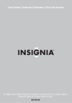
Caution regarding installation
Note
Wall
Do not block ventilation openings or stack other equipment on the top.
Note: For heat dispersal, do not install this unit in a confined space such as a bookcase or similar enclosure.
2
Table of Contents
2 Safety Information
26 Operating Your System
5
What's Included
6
Installing the Remote Control Battery
6
Operating the range of the Remote Control
7 Parts Description
7
Front Panel
8
Front Display
8
Rear Panel
9Remote Control
10Making Connections
English
26 Listening to Your System
5 Getting Started
26 Basic Operation
26 Muting the Sound
27 Enjoying Surround Effects
27 Setting the Surround Mode
30 Cancelling the Surround Mode for Stereo
Operation
30 Adjusting the Current Channel Level
31 Listening to Music on USB
31
31
31
32
32
To Stop Playback
To Pause Playback
To Skip Forward or Backward
To Play Repeatedly
To Play Randomly
32 Listening to Internet Radio
33 Listening to Music from the Media Server
10 Connection Overview
11 Connecting Speakers
11 Placing Speakers
13 Connecting Speakers
14 Setting the Speaker
15 Connecting a TV
15 Connecting with an HDMI TV
16 Connecting with a non-HDMI TV
17 Connecting Playback Components
17
17
18
20
Connecting HDMI Components
Connecting Video Components
Connecting Audio Components
Connecting Recording Components
33 Configuring the Windows Media Player
34 Listening to Music from the Media Server
34 Using the Sherwood Remote Application
34 Preparing for the Application
35 Using the Application
39 Listening to FM Radio
39
39
39
40
40
40
Auto Tuning
Manual Tuning
Manual Presetting
Auto Presetting
Tuning in to Preset Stations
RDS Tuning
41Recording
20 Connecting to a Network
21 Connecting an Antenna
21 Connecting FM Antenna
22 Connecting AM Antenna
23 Connecting to Muti-Room
24 Connecting to the System's Internal Amplifier
24 Connecting to an External Amplifier
25 Controlling Room2
25 Connecting Power
3
R-807 Network AV Receiver
42 Customizing Settings
42 Setting the System
43 Setting Options Overview
44 Setting the System Setup
44 AMP Assign
44 Automatic Power Control
44 Network Standby Control
44 Setting the Speaker Setup
44
46
46
46
46
Auto Setup
Speaker Setup
Speaker Crossover
Speaker Distance
Speaker Channel Level
47 Setting the HDMI Setup
47HDMI
47 CEC Control
47 Setting the Surround Parameter Setup
47 Height Gain
47PANORAMA
47 Center Width
47Dimension
47 Center Image
48DRC
48Tone
48 Sound Delay
48 Low Frequency Effect
49 Setting the Multi Room Setup
49 Setting the Network Setup
49 Network Settings Overview
49 Setting the Direct Wireless Network
Connection
50 Setting the Wired Network Connection
50 Setting Other Network Options
50 Viewing the Network Information
4
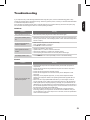
51Troubleshooting
51GENERAL
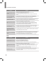
51SOUND
52VIDEO
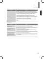
53 USB device
54 NETWORK CONNECTION
54 Important Information Regarding the HDMI
Connection
55 Additional Information
55 Specifications
56 Trademarks and Licenses
56 DTS-HD Master Audio
56 Dolby TrueHD
56HDMI
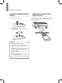
Getting Started
English
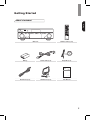
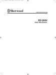
What's Included
Main unit
Battery
Remote control (1 ea)
Power Cable (1 ea)
Setup Mic (1 ea)
R807
NETWORK AV RECE VER
OP RA ING NS RUC IONS
FM antenna (1 ea)
AM Antenna (1 ea)
User Manual
5
R-807 Network AV Receiver
Installing the Remote Control
Battery
1
2
Remove the battery cover.
Insert two AAA size batteries with the polarity
matched properly.
Caution
•• Always use alkaline batteries, and do not use the
rechargeable batteries (Ni-Cd type).
•• If the batteries run out, remove the old batteries
and replace them with new ones within several
minutes.
•• If the batteries are removed or have been
exhausted for a longer period of time, memorized
contents will be cleared. In this case, you should
memorize them again.
•• If the battery is placed incorrectly, it can cause
explosion.
•• Remove the battery if the remote control is not
used for a long period of time.
•• Do not leave the product in a hot or humid place.
•• Do not handle and store the battery with metallic
tools.
6
Operating the range of the
Remote Control
Use the remote control within a range of about 7 meters
(23 feet) and angles of up to 30 degrees aiming at the
remote control sensor.
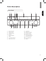
Parts Description
1
2
9
1
2
3
4
5
6
7
8
3
45
10 11 12
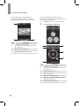
Main Power Switch
Standby Indicator
On/Standby Switch
IR Sensor
Band Select Button
Display
Surround Select Buttons
Master Volume Control
6
13
7
14
9
10
11
12
13
14
15
16
15
English
Front Panel
8
16
Input Selector
Headphone Connector
Aux Input Connector
Setup MIC Connector
Tuning Up/Down Buttons
Preset Select Buttons
Stereo Mode Button
USB Port
7
R-807 Network AV Receiver
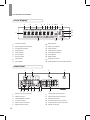
Front Display
2
3
4
5
6
7 8
9 10 11
12
13
14
15
1
18
1
2
3
4
5
6
7
8
9
17
10
11
12
13
14
15
16
17
18
Information Display
Dolby Digital Surround indicator
Auto Detecting Indicator
RDS Indicators
Stereo Indicator
Tuning indicator
Room2 Indicator
USB Indicator
MP3 Indicator
16
WMA Indicator
Sleep Timer Indicator
Preset Indicator
Station Memory Indicator
Preset Station Indicator
Direct Indicator
HDMI Indicator
Digital Input Indicator
Dolby/DTS/DSP Surround mode indicators
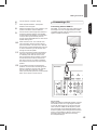
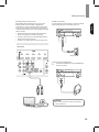
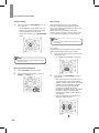
Rear Panel
1
5
1
2
3
4
5
6
8
6
2
7
8
Monitor OUT (ARC) Connector
HDMI Connectors
LAN/ETHERNET Connector
AC Input Connector
Radio Antenna Connectors
Digital Audio Connectors
3
9
10 11
4
12
7
8
9
10
11
12
Analog Audio Input Connectors
Analog Audio Output Connectors
Subwoofer Connector
Composite Video Input Connectors
Composite Video Output Connectors
Speaker Connectors
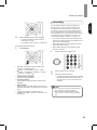
Parts Description
Remote Control
1
2
24
23
22
3
21
1
2
3
4
5
6
20
4
5
6
19
18
17
16
Power On Button
Room2 Input Select Button
Source Select Buttons
Surround Select Buttons
Top Menu Button
▲/▼/◄/►
Select Buttons
ENTER/MEMO Enter/Memory Button
SEARCH.M
7
8
9
10
English
25
RDS Search Button
Display/Mode Button
Stop Button
Repeat Button
Tuning Up/Down Buttons
Rewind/Fast forward Buttons
15
11
Preset Station Up/Down Buttons
Previous/Next Buttons
7
8
9
10
14
13
12
11
12
13
14
15
16
17
18
19
20
21
22
23
24
25
Random Button
Play/Pause Button
Return Button
Volume Up/Down Buttons
Setup Menu Button
Mute Button
Stereo Mode Button
Audio Assign Button
Channel Level Button
Test Tone Sequence Button
Tone Control Button
Room2 ON/OFF Button
Standby Button
Room2 Volume Up/Down Buttons
9
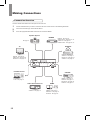
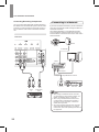
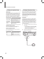
Making Connections
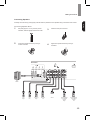
Connection Overview
Connect various external devices to the ports on the main unit.
1
2
3
Find an external device you want to connect to the main unit as shown on the following illustration.
Check the connection type of the external device.
Go to the appropriate illustration and check the connection details.
Speaker System
BD/BDR
See page 11.
HDMI IN - See page 15.
VIDEO IN/OUT - See page 17, 20.
DIGITAL IN - See page 18.
AUDIO IN/OUT - See page 19, 20.
DVD/DVR
TV
HDMI IN - See page 15.
VIDEO IN - See page 17.
DIGITAL IN - See page 18.
AUDIO IN - See page 19.
HDMI IN - See page 15.
VIDEO OUT - See page 16.
DIGITAL IN - See page 18.
Portable Devices
STB/CBL
F.AUX - See page 19.
Audio External Devices
AUDIO IN - See page 19.
10
GAME
HDMI IN - See page 15.
DIGITAL IN - See page 18.
AUDIO IN - See page 19.
HDMI IN - See page 15.
VIDEO IN - See page 17.
DIGITAL IN - See page 18.
AUDIO IN - See page 19.
Making Connections
Connecting Speakers
English
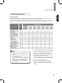
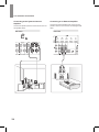
Placing Speakers
Determine the locations for your speaker placement according to their manufacturer’s directions and the layout of
your listening room. Use the illustration on page 12 as a guide for speaker placement.
To create the most realistic surround-sound environment possible, you should place your speakers in a circle around
the listener. You should angle each speaker so it directly faces the listening position. Use the diagram below as a
guide.
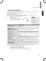
Speaker System
Speaker Type
Abbr.
7.1 Channel
(for Dolby
Pro Logic IIz
playback)
7.1
Channel
6.1
Channel
5.1
Channel
4.1
Channel
3.1
Channel
2.1
Channel
Front Left
FL
●
●
●
●
●
●
●
Front Right
FR
●
●
●
●
●
●
●
Front Height Left
FHL
●
Front Height Right
FHR
●
C
●
●
●
●
Subwoofer
SW
●
●
●
●
●
Surround Left
SL
●
●
●
●
●
Surround Right
SR
●
●
●
●
●
Surround Back Left
SBL
●
Surround Back
Right
SBR
●
Surround Back
SB
Center
●
●
●
●
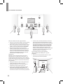
Front left and right speakers and center speaker
Note
•• If you’re using only one surround back speaker,
connect it to the surround back left speaker
terminals.
•• Front high and surround back speakers cannot
be used at the same time.
•• To avoid interference with the TV picture when
using a conventional TV, use only magnetically
shielded front left, right, and center speakers.
•• To obtain the best surround effects, all the
speakers except the subwoofer should be full
range speakers.
•• Place the front speakers with their front surfaces as
flush to the TV or monitor screen as possible.
•• Place the center speaker between the front left and
right speakers and its distance should not be further
from the listener than the front speakers.
•• Place each speaker so that sound is aimed at where
listener's ears would be in the main listening position.
Surround left and right speakers
•• Place the surround speakers approximately 60 ~
90 cm (24 ~ 36 inches) above on the direct left/
right side or slightly behind the ear level of a seated
listener.
11
R-807 Network AV Receiver
FHR
FHL
TV
FL
SW
FR
C
SR
SL
SBL
SBR
SB
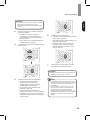
Surround back left and right speakers
•• Place the surround back speakers at the back facing
forward together and closer than front speakers.
•• When using a single surround back speaker, place it
at the rear center facing forward at a slightly higher
position (0 to 20 cm) than the surround speakers.
•• We recommend installing the surround back
speaker(s) facing slightly. This effectively prevents
the surround back channel signals from bouncing
off the TV or screen at the front center, resulting in
interference and making the sense of movement
from the front to the back less sharp.
Subwoofer
Because a room’s shape and volume can have a
dramatic effect on a subwoofer’s performance, you
should experiment with placement in order to find the
location that produces the best results in your particular
listening room. With that in mind, these rules will help
you get started.
•• In some rooms, the best performance comes from
placing the subwoofer behind the listener. A good
way to determine the best location for the subwoofer
is by temporarily placing it in the listening position
and playing music with strong bass content. Move
around to various locations in the room while the
system is playing (putting your ears where the
subwoofer would be placed), and listen until you find
the location where the bass performance is best.
Place the subwoofer in that location.
Front height left and right speakers
(Recommended for Dolby Pro Logic IIz
playback)
•• Place the front height speakers at least 1 meter
(40 inches) above the front speakers.
Front height
speaker
•• Placing the subwoofer next to a wall generally will
increase the amount of bass in the room.
•• Placing the subwoofer in a corner generally will
maximize the amount of bass in the room.
•• In many rooms, placing the subwoofer along the
same plane as the left and right speakers can
produce the best integration between the sound of
the subwoofer and that of the left and right speakers.
12
Surround
speaker
At least 1 m
60 ~ 90 cm
Front
speaker
Surround back
speaker
Making Connections
Connecting Speakers
English
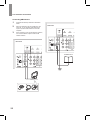
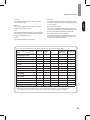
Carefully check the left (L) and right (R) channels and the polarities on the speakers being connected to this receiver.
Connecting Speaker Wires
1
2
Strip away approx. 10 mm (3/8 inch) of wire
insulation, and then tightly twist the wire ends.
3
4
Loosen the speaker terminal by turning it
counter-clockwise.
Insert the bare part of the wire.
Tighten the speaker terminal by turning it
clockwise.
Rear Panel
Sub
Woofer
Font
Right
Font
Left
Surround
Right
Surround
Left
Center
Surround Back/
Front Height/
Room2
Right
Surround Back/
Front Height/
Room2
Left
13
R-807 Network AV Receiver
•• Be sure to connect speakers firmly and accurately
according to the channel (left and right) and the
polarity (+ and −). If the connections are incorrect, no
sound will be produced by the speakers, and if the
polarity of the speaker connection is incorrect, the
sound will be unnatural and tinny.
•• When listening in Dolby Pro Logic IIz mode, connect
the front height speakers.
•• To install the speakers, see “Placing Speakers” on
page 11.
•• For ROOM 2 playback, connect the ROOM
2 speakers. For details, see “Connecting to
Multi‑Room” on page 23.
•• After installing the speakers, first adjust the speaker
settings according to your environment and speaker
layout. For details, see “Setting the Speaker”.
Caution
•• Be sure to use the speakers with the impedance
of 6 ohms or above.
•• Do not let bare speaker wires touch each other or
any metal part of this receiver. This could damage
the main unit and/or the speakers.
•• Never touch the speaker terminals while the AC
input cord is connected to the wall AC outlet.
Doing so could result in electric shock.
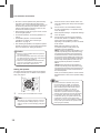
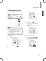
Setting the Speaker
You will be using the following remote control buttons
to configure the main unit. For details on the speaker
setup, see page 44.
2
3
4
5
Press the remote control’s SETUP button. The
main unit’s OSD System Setup menu will appear
on the TV.
Use the remote’s arrow and ENTER buttons
to select “Speaker Setup”. The Speaker Setup
menu will appear.
Select “Speaker Settings”. The Speaker Settings
menu will appear.
Use the remote’s left and right arrow buttons
to select OFF, SMALL or LARGE for the Front,
Center and Surround speaker positions,
depending on the speakers you have connected
to the receiver.
OFF: Select this setting if you have not
connected a speaker in that position (not
available for the front speakers).
SMALL: Select this setting if the speaker is not
capable of producing clean, deep bass energy
at output levels that match those produced by
a powered subwoofer. All bass in that channel
is removed from that speaker and is sent to the
subwoofer (or to the front speakers if subwoofer
is set to NO). Most speakers (unless they are
large and powerful) should be considered
SMALL.
LARGE: Select this setting if the speaker is
capable of producing clean, deep bass energy
at output levels that match those produced by a
powered subwoofer. All bass in that channel is
sent to that speaker.
When you’re finished, press the remote control’s
RETURN button to return to the Speaker Setting
menu.
Note
1
Turn on your TV and select the TV input.
Note
•• Although you can configure the main unit using
only its front-panel message display, it is much
easier to use the On-Screen Display (OSD) menu
system.
14
•• If your system has a subwoofer and you set
the front speakers to LARGE, the subwoofer
may only play Dolby Digital-audio signals and
DTS-encoded program material that contains
LFE channel information. If you set your
front speakers to LARGE and you want your
subwoofer to reproduce bass from all program
material, set the Subwoofer to PLUS (see below).
•• For subwoofer, select YES (if your system has
a subwoofer), NO (if your system does not have
a subwoofer), or PLUS (if your system has a
subwoofer, you set your front speakers to LARGE
and you want your subwoofer to reproduce bass
from all program material).
Making Connections
You can skip the “Crossover” setting.
8
Measure the distance from each speaker in your
system to the listener. Set the distances.
9
10
11
12
Select “Speaker Distance”. The Speaker
Distance menu will appear.
Use the remote’s left and right arrow buttons to
change the distance setting for each speaker
so that it matches the distance you wrote down
in step 8. When you’re finished, press the
remote control’s RETURN button to return to the
Speaker Setting menu.
Connecting a TV
Connecting with an HDMI TV
English
6
7
With HDMI, you can easily enjoy high quality sounds
and images. The main unit plays audio from HDMI
compatible products while also passing on the video
signal to a HDMI-connected TV.
Select “Channel Level”. The Channel Level
menu will appear. Use the remote’s left and
right arrow buttons to set Test Tone to “Manual”
and press the remote’s ENTER button. After the
on-screen countdown you will hear test noise
through the front left speaker.
Sit in the main listening position and adjust the
main unit’s volume control so the test sound
is moderately loud. Note the volume of the
test sound through the first speaker. Press the
remote’s down arrow button to advance the
test noise to each of your system’s speakers
and note the volume level of the noise in each
speaker.
As you advance the test sound through the
speakers, use the remote’s left and right arrow
buttons to adjust the volumes of the channels
until all of them play at the same volume.
When you’re finished, press the remote’s SETUP
button to turn off the on-screen menus.
Rear Panel
About HDMI
HDMI (High Definition Multimedia Interface) supports
both audio and video on a single digital connection
for use with DVD players, DTV, set-top boxes, and
other AV devices. HDMI was developed to provide
the technologies of High Bandwidth Digital Content
Protection (HDCP) as well as Digital Visual Interface
(DVI) in one specification. HDCP is used to protect
the digital content transmitted and received by
DVI‑compliant displays.
15
R-807 Network AV Receiver
HDMI has the capability to support standard,
enhanced, or high-definition video plus standard to
multi-channel surround-sound audio. HDMI features
include uncompressed digital video, a bandwidth of up
to 2.2 gigabytes per second (with HDTV signals), one
connector (instead of several cables and connectors),
and communication between the AV source and AV
devices such as DTVs.
This main unit is also compatible with the DeepColor
and x.v.Color feature (x.v.Color is trademarks of Sony
Corporation).
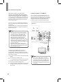
Connecting with a non-HDMI TV
If your TV does not have an HDMI connector, or if
your TV does have an HDMI connector but you are
connecting some source devices with only composite
video connectors, use a composite video cable (not
included) to connect the composite Monitor Out
connector to your TV’s composite video connector.
Rear Panel
HDMI, the HDMI logo and High-Definition Multimedia
Interface are trademarks or registered trademarks of
HDMI Licensing, LLC.
Note
•• Check the setup of the connected component
if an image is poor or there is no sound from a
component connected via the HDMI cable.
•• Audio signals (sampling frequency, bit length,
etc.) transmitted from an HDMI jack may be
suppressed by the connected component.
•• When the connected component is not
compatible with copyright protection technology
(HDCP), the image and the sound from the HDMI
TV OUT jack may be distorted or may be not
output. In this case, check the specification of the
connected component.
•• Regardless of which input is selected for the
system, the video signal from the HDMI input jack
(BD, DVD, SAT) that was last selected is output
from the HDMI TV OUT jack.
Composite Video Cable
(not supplied)
TV
Confirming the HDMI control functions
Composite
VIDEO IN
To use the HDMI control functions properly, it is
recommended to confirm the HDMI control functions
usable with each connected component by performing
the following operations.
1
2
Turn on all the components connected with HDMI
cables.
Turn the TV off to standby mode.
•• Confirm that all the components are turned off.
3
With all the components off, start playback of a
device (connected with HDMI cable).
4
Confirm that all the components are turned on and
the inputs of the main unit and TV are switched
automatically.
16
Note
•• The on-screen display (OSD) only appears
through the Composite Monitor Out connector.
If you want to use the main unit's OSD menus
you will need to connect its Composite Monitor
Out connector to your TV even if you are not
connecting any composite video source devices
to the system.
Making Connections
Source devices are components from which a playback
signal originates, e.g., a Blu-ray Disc™ or DVD player;
a set-top box, or HDTV tuner, etc. The receiver has
several different types of input connectors for your
audio and video source devices: HDMI, composite
video, optical digital audio, coaxial digital audio and
analog audio.
Connecting Video Components
You will need to make composite video connections
from your source devices that do not have HDMI video
connections. You will also need to make an audio
connection from the device to the main unit.
English
Connecting Playback
Components
Rear Panel
Connecting HDMI Components
If any of your source devices have HDMI connectors,
using those connectors will provide the best possible
video and audio performance quality. Since the HDMI
cable carries both digital video and digital audio
signals, you do not have to make any additional audio
connections for devices you connect via HDMI cables.
If you have an HDMI or DVI (with HDCP) equipped
component (Blu-ray disc player, etc.), you can connect
it to this receiver using a commercially available HDMI
cable.
Rear Panel
Composite Video Cable
(not supplied)
Composite
VIDEO OUT
Composite Video-Equipped
Source Device
HDMI Cable
(not supplied)
HDMI-Equipped Source
Device
17
R-807 Network AV Receiver
Connecting Audio Components
Coaxial Digital Audio Connection
Optical Digital Audio Connection
If your source devices have a coaxial digital output,
connect it to the main unit's coaxial digital audio
connector.
You can connect components equipped with an optical
output jack. On the main unit, you can enjoy the full
sound of components, such as DVD players, set-top
box, BD (Blu-ray Disc™) players or TVs.
* “Blu-ray Disc” is a trademark of Blu-ray Disc
Association.
Rear Panel
Rear Panel
OUT
OPTICAL
OUT
TV, DVD Player, etc.
TV, DVD Player, etc.
18
Making Connections
F.AUX Connection
Make analog audio connections from your source
devices that do not have HDMI or digital audio
connections. If you’re connecting video sources to the
main unit, you must also connect the source device’s
composite video output to the corresponding composite
video connector.
You can use the F.AUX input jack to connect portable
audio components such as an MP3 player, etc.
English
Analogue Audio Connection
•• Ensure the left (L) and right (R) channels and the
inputs and outputs are correctly connected.
•• To listen to the sound of a connected audio device,
select AUX as the input source.
•• To listen to TV audio, select TV as the input source.
Rear Panel
MP3 player, etc.
Listening with Headphones
1
R
Connect the headphones to the PHONES jack
on the front panel.
L
Caution
•• Be careful not to set the volume too high when
using headphones.
TV, DVD Player, etc.
19
R-807 Network AV Receiver
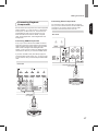
Connecting Recording Components
You can connect video and audio recording devices to
the VIDEO OUT and AUDIO OUT jacks. You can make
an audio or a video recording from the built-in tuner or
from an audio or video source connected to the main
unit.
Rear Panel
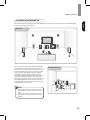
Connecting to a Network
If you have an internet connection, you can connect the
main unit to the internet as well as using a wireless or a
wired LAN connection.
The following illustration is a configuration example
of a home network with the system and a server. It is
recommended to connect the server to the router with a
wired connection.
Modem
Internet
To WAN side
Router
PC
To LAN port
To LAN port
LAN port/Ethernet connector
Main Unit
R
AUDIO
IN
L
IN
(COMPOSITE)
VIDEO
Note
•• After making a broadband internet connection,
you should set the communication settings. For
details, see “Network Setup” on page 49.
•• When using a broadband internet connection,
a contract with an internet service provider is
required. For more information, contact local
internet service provider.
•• Since the connected equipment and connection
method may differ depending on your internet
environment, refer to the operating instructions of
the equipment.
20
Making Connections
Connecting an Antenna
Connecting FM Antenna
To strengthen the signal reception, extend the antenna
to its full length.
Outdoor Antenna
1
2
English
To listen to radio stations, connect the FM wire antenna
and AM loop antenna as illustrated below.
Remove the indoor antenna if it is connected.
Connect the FM outdoor antenna to the FM
antenna terminal.
Indoor Antenna
1
2
Connect the FM indoor antenna to the FM
antenna terminal.
Change the position of the antenna until you get
the best reception of your favorite FM stations.
Rear Panel
Rear Panel
21
R-807 Network AV Receiver
Connecting AM Antenna
1
2
3
Assemble the AM loop antenna as illustrated
below.
Place the antenna as far as possible from the
main unit, TV set, speaker cords and the AC
input cord, and set the direction for the best
reception.
Rear Panel
If the reception is poor with the AM loop antenna,
it is recommended to replace it with an AM
outdoor antenna.
Rear Panel
AM Outdoor Antenna
AM Loop Antenna
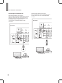
22
Making Connections
Connecting to Muti-Room
English
The multi-zone function allows you to play back different input sources in the room where the unit is installed (Main
Room) and in another room (Room2).
Main Room
You can enjoy sounds from the equipment connected
to the main unit in a room other than the main room.
For example, you can watch the DVD in the main room
and listen to a CD in the sub room. The main unit can
power up to two independent systems in separate
rooms after you have made the proper multi-room
connections. Different sources can play in two rooms
at the same time or, depending on your needs, the
same source can also be used. The main and sub room
have independent power (the main room power can
be off while sub room is on) and the sub room can be
controlled by the remote control.
Sub Room (Room2)
Note
•• When the Room2 output is enabled, the surround
back speakers in the main room do not produce
sound.
•• Remove the unit’s power cable from the AC wall
outlet before connecting speakers or an external
amplifier.
23
R-807 Network AV Receiver
Connecting to the System's Internal
Amplifier
Connect the speakers placed in Room2 to the main unit
with speaker cables.
Rear Panel
Connecting to an External Amplifier
Connect the external amplifier (with volume control)
placed in Room2 to the main unit with analogue audio
cable.
Rear Panel
External Amplifier Audio Input
24
Making Connections
4
Connect the external amplifier (with volume control)
placed in Room2 to the unit with analogue audio cable.
You can select different sources for main room and
second room (ROOM 2) and play them at the same
time.
1
•• The tone level can be adjusted within the
range of -10 ~ +10 dB.
•• In general, we recommend the bass and
treble to be adjusted to 0 dB (flat level).
Press ROOM2 on the remote control.
•• The ROOM 2 indicator is displayed on the
fluorescent display.
Caution
•• Extreme settings at high volume may damage
your speakers.
5
2
Adjust the tone (bass and treble) for ROOM 2
source.
English
Controlling Room2
Use the remote’s left and right arrow buttons
to select OFF, SMALL or LARGE for the Front,
Center and Surround speaker positions,
depending on the speakers you have connected
to the receiver.
Press the ROOM2 input select button to select
the desired mode.
•• Each time the button on the universal remote
control is pressed, the input source changes
in the following order:
DVD STB AUX F.AUX TUNER
Connecting Power
Make sure to plug in only after you have connected all
your components to the main unit. Plug the supplied AC
input cord into the AC inlet and then into the wall outlet.
Rear Panel
Note
•• If you press the ROOM 2 INPUT SELECTOR
button when the ROOM 2 function is off, it is
automatically turned on.
3
Adjust the ROOM 2 volume by pressing the
ROOM 2 VOLUME UP(+)/DOWN(−) buttons.
AC power cord
To he wall outlet
25
Operating Your System
Listening to Your System
Basic Operation
You can listen to audio by following the basic
procedures below.
1 Turn on the connected component.
2
4
Start playback of the component you selected in
step 1.
5
During playback, you can adjust the volume
level.
•• On the main unit, rotate the volume controller.
•• On the remote control, press VOLUME -/+.
Turn on the main unit.
•• On the main unit, press POWER and ON/
STANDBY.
•• On the remote control, press POWER ON
and STANDBY.
VOL -
VOL +
Muting the Sound
Note
•• When the power button is pressed on the main
unit, you cannot turn on the main unit by pressing
the power button on the remote control.
3
You can mute the sound temporarily by pressing MUTE.
1
Press MUTE to mute the sound.
Select the input source you want to play back.
•• On the main unit, rotate INPUT SELECTOR.
•• Each time the button is pressed, the display
changes in the following order:
BD/BDR DVD/DVR STB/CBL GAME
AUX NETWORK USB TV F.AUX
TUNER
•• On the remote control, press a source select
button.
INPUT SELECTOR
26
2
Press MUTE or VOLUME -/+ to turn on the
sound.
Operating Your System
Enjoying Surround Effects
English
This main unit incorporates a sophisticated Digital Signal Processor that allows you to create optimum sound quality
and sound atmosphere in your personal Home Theater.
Setting the Surround Mode
Before surround playback, first perform the speaker setup procedure, etc. on the OSD settings for optimum
performance. For details, see “Setting the Speaker Setup” on page 44.
1 Select the desired surround mode by pressing
the SURROUND buttons.
•• Each time the buttons are pressed, the
surround mode changes depending on the
input signal format as the table below:
Signal format being input
Selectable surround mode
Dolby Digital Plus sources
DOLBY DIGITAL PLUS
Dolby TrueHD sources
DOLBY TRUEHD
Dolby Digital EX 6.1 channel
sources
Dolby Digital 5.1 channel
sources
<DOLBY DIGITAL EX, DOLBY D + PLIIx MUSIC>, (DOLBY D + PLIIx MOVIE),
{DOLBY D + PLIIz}, DOLBY DIGITAL, DSP Surround modes*
Dolby Digital 2 channel
sources
<DOLBY PLIIx MOVIE, DOLBY PLIIx MUSIC, DOLBY PLIIx GAME>, [DOLBY
PLII MOVIE, DOLBY PLII MUSIC, DOLBY PLII GAME], {DOLBY PLIIz
HEIGHT}, DTS NEO: 6 MUSIC, DTS NEO: 6 CINEMA, DSP Surround modes*
DTS-HD High Resolution
Audio sources
DTS-HD HRA
DTS-HD Master Audio sources
DTS-HD MSTR
DTS ES Discrete/Matrix 6.1
channel sources
<Corresponding DTS ES mode, DTS + PLIIx MUSIC>, (DTS + PLIIx MOVIE),
DTS, {DTS + PLIIz}, DSP Surround modes*
DTS sources
DTS 96/24 sources
Corresponding DTS mode, <DTS + NEO: 6, DTS + PLIIx MUSIC>, (DTS +
PLIIx MOVIE), DTS, {DTS + PLIIz}, DSP Surround modes*
PCM (multi-channel) sources
**
MULTI PCM, <MCH + PLIIx MOVIE, MCH + PLIIx MUSIC>, {MCH + PLIIz},
DSP Surround modes*
PCM (2 channel) sources
Analog stereo sources
Music files from USB
<DOLBY PLIIx MOVIE, DOLBY PLIIx MUSIC, DOLBY PLIIx GAME>, [DOLBY
PLII MOVIE, DOLBY PLII MUSIC, DOLBY PLII GAME], DTS NEO: 6 MUSIC,
DTS NEO: 6 CINEMA, {DOLBY PLIIz HEIGHT}, DSP Surround modes*
Depending on surround back speaker setting, some surround modes can be selected or not as follows:
< >
[ ]
( )
{ }
*
**
:
:
:
:
:
:
Possible only when surround back speaker is not set to “NO”.
Possible only when surround back speaker is set to “NO”.
Possible only when surround back speaker is set to “2ch”.
Possible only when front height speaker is set to “ON”.
Stand for THEATER, MOVIE, HALL, GAME, STADIUM, MCH STEREO, ALC.
on the signal format being input, the Do by Pro Logic IIx modes may not be selected.
27
R-807 Network AV Receiver
DTS Digital Surround
Dolby Digital
DTS Digital Surround (also called simply DTS) supports
up to 5.1 discrete channels and uses less compression
for high fidelity reproduction. Use it with DVDs and CDs
bearing the DTS logo.
Dolby Digital is the multi-channel digital signal format
developed by Dolby Laboratories. Discs bearing
the Dolby Digital logo include the recording of up to
5.1 channels of digital signals. This will put you right
in the middle of the action, just like being in a movie
theater or concert hall.
DTS-ES™ Discrete 6.1
This is a 6.1 channel discrete digital audio format
which adds a surround back channel to the DTS
digital surround sound. The seven totally separate
audio channels provide better spatial imaging and
360 degrees sound localization, perfect for sounds that
pan across the surround channels. Use it with DVDs
bearing the DTS-ES logo, especially those with a DTS
ES Discrete sound track.
Dolby Digital EX
This mode expands 5.1-channel sources for
6.1/7.1 channel playback. It's especially suited to Dolby
Digital EX soundtracks that include a matrix-encoded
surround back channel. The additional channel adds an
extra dimension and provides an enveloping surround
sound experience, perfect for rotating and fly-by sound
effects.
DTS - ES™ Matrix 6.1
This is a 6.1 channel discrete digital audio format
inserting a surround back channel to the DTS digital
surround sound through matrix encoding. Use it with
DVDs bearing the DTSES logo.
DTS Neo: 6™ Surround
DTS Neo: 6 is a matrix decoding technology for
achieving 7.1 channel surround playback with 2 channel
sources. It includes 'DTS Neo: 6 Cinema’ suited for
playing movies' and 'DTS Neo: 6 Music’ suited for
playing music'.
DTS 96/24
This is high resolution DTS with a 96 kHz sampling rate
and 24 bit resolution, providing superior fidelity. Use it
with DVDs bearing the DTS 96/24 logo.
DTS-HD High Resolution Audio
Developed for use with HDTV, including the new video
disc formats Blu-ray and HD DVD, this is the latest
multi-channel audio format from DTS. It supports up
to 7.1 channels with 96 kHz/24 bit sampling rate and
signal resolution.
DTS-HD Master Audio
Designed to take full advantage of the additional
storage space offered by the new Blu-ray and HD
DVD disc formats, this new DTS format offers up to
7.1 discrete channels of uncompressed digital audio
with 96 kHz/24 bit sampling rate and signal resolution.
Manufactured under license under U.S. Patent Nos:
5,956,674; 5,974,380; 6,226,616; 6,487,535; 7,212,872;
7,333,929; 7,392,195; 7,272,567 & other U.S. and
worldwide patents issued & pending. DTS-HD, the
Symbol, & DTS-HD and the Symbol together are
registered trademarks & DTS-HD Master Audio is a
trademark of DTS, Inc. Product includes software.
© DTS, Inc. All Rights Reserved.
Dolby Digital Plus
Developed for use with HDTV, including the new video
disc formats Blu-ray and HD DVD, this is the latest
multichannel audio format from Dolby. It supports up
to 7.1 channels with 48 kHz/24-bit sampling rate and
signal resolution.
Dolby TrueHD
Designed to take full advantage of the additional
storage space offered by the new Blu-ray and HD
DVD disc formats, this new Dolby format offers up to
7.1 discrete channels of lossless audio performance
with 96 kHz/24 bit sampling rate and signal resolution.
Dolby Pro Logic IIz
This mode adds front height channels to surround
sound, creating a 7.1 channel palyback for music,
movies and video games. Dolby Pro Logic IIz brings
enhanced spatial effects, added depth, and an overall
airiness to listening experience.
Dolby Pro Logic IIx
This mode expands any 2-channel source for
7.1-channel playback. It provides a very natural
and seamless surround sound experience that fully
envelopes the listener. As well as music and movies,
video games can also benefit from the dramatic spatial
effects and vivid imaging. It includes ‘Dolby Pro Logic
IIx Movie’ suited for playing movies, ‘Dolby Pro Logic IIx
Music’ suited for playing music and ‘Dolby Pro Logic IIx
Game’ suited for playing games.
Dolby Pro Logic II
If you are not using any surround back speakers, Dolby
Pro Logic II surround will be used instead of Dolby Pro
Logic IIx surround. It includes Dolby Pro Logic II Movie,
Dolby Pro Logic II Music and Dolby Pro Logic II Game
like Dolby Pro Logic IIx surround.
Manufactured under license from Dolby Laboratories.
Dolby, Pro Logic, and the double-D symbol are
registered trademarks of Dolby Laboratories.
28
Theater
Stadium
This mode provides the effect of being in a theater
when watching a play.
This mode provides an expansive sound field in order
to achieve a true stadium effect when watching baseball
or soccer games.
Movie
Multi Channel Stereo
This mode provides the effect of being in a movie
theater when watching a movie.
This mode is designed for playing background music.
The front, surround and surround back channels create
a stereo image that encompasses the entire area.
Hall
This mode provides the ambience of a concert hall for
classical music sources such as orchestral, chamber
music or an instrumental solo.
ALC (Auto Volume Level Control)
This mode automatically equalizes playback sound
levels if each sound level varies with the music source
recorded in a portable audio player.
Game
This mode is suitable for video games.
•• The sound from each channel can be reproduced according to the surround modes as follows:
Channels
FRONT L/R
CENTER
Modes
SURROUND
SURROUND
BACK/FRONT
L/R
HEIGHT L/R
DTS-HD HIGH RESOLUTION
AUDIO/MASTER AUDIO
O
O
O
SUBWOOFER
O/-
O
DTS, DTS 96/24
O
O
O
-
O
DTS ES DISCRETE/MATRIX
O
O
O
O
O
DTS NEO: 6 CINEMA/MUSIC
O
O
O
O
- (*)
DOLBY DIGITAL PLUS/DOLBY
TRUEHD
O
O
O
O/-
O
DOLBY DIGITAL
O
O
O
-
O
DOLBY DIGITAL EX
O
O
O
O
O
DOLBY PRO LOGIC IIz HEIGHT
O
O
O
O
O
DOLBY PRO LOGIC IIx MOVIE/
MUSIC/GAME
O
O
O
O
O
DOLBY PRO LOGIC II MOVIE/
MUSIC/GAME
O
O
O
-
O
(MULTI) PCM
O
O
O
O/-
O
AUTO VOLUME LEVEL CONTROL
O
-
-
-
- (*)
Other Surrounds
O
O
O
O
- (*)
STEREO
O
-
-
-
- (*)
(*): Depending on the subwoofer setting, the sound from the subwoofer channel may be reproduced.
•• Depending on the speaker settings and the number of the encoded channels, etc., the sound from the
corresponding channels may not be reproduced. For details, see “Setting the Speaker” on page 44.
29
English
Operating Your System
R-807 Network AV Receiver
Cancelling the Surround Mode for Stereo
Operation
1
Press STEREO.
•• Depending on the input signal format, either
the stereo mode or the 2CH downmix mode is
selected.
2
To cancel either the stereo mode or the 2CH
downmix mode, press the SURROUND buttons
to select the surround mode.
Adjusting the Current Channel Level
After adjusting each channel level with test tone, adjust
the channel levels according to the program sources or
to suit your tastes.
1
Press the CHANNEL LEVEL button.
2
Select the desired channel by pressing or .
•• Each time the buttons are pressed, the
corresponding channel changes as follows:
FL [ FHL] C [ FHR] FR
SR ( SBR SBL) SL SW
( ) : Poss ble when the surround back channel
is set to “2ch” or “1ch”.
[ ] : Poss ble only when the front height
speaker is not set to “NO”.
Note
•• 2 CH downmix mode allows the multi-channel
signals encoded in DTS or Dolby Digital format,
etc. to be mixed down into 2 front channels and
to be reproduced through only two front speakers
or through headphones.
•• If headphones are plugged in to the main unit
while playing the multi-channel digital signals
from DTS or Dolby Digital sources, etc., it will
enter the 2CH downmix mode automatically.
Note
•• Depending on the speaker settings (such as “NO”)
and surround mode, some channels cannot be
selected.
3
4
30
Adjust the level of the selected channel as
desired by pressing or .
Repeat the steps 2 and 3 to adjust each channel
level.
Operating Your System
Listening to Music on USB
English
You can play audio files from a USB device.
However, editing or copying a data file is not possible.
To Pause Playback
1
During playback, press
.
•• Playback will stop at the point where the
button is pressed.
•• To resume playback from this point, press the
button again.
USB storage device
Note
•• The USB jack does not support the connection of
other USB devices except for a USB flash drive
or a USB memory card reader.
•• When the USB device does not fit into the USB
jack, a USB extension cable is required.
•• You can play back only the content from a
connected USB device.
•• Copy-protected contents are not playable.
To Stop Playback
1
During playback, press
To Skip Forward or Backward
1
.
During playback, press
or
.
•• Each time the button is pressed, a track is
skipped forward or backward.
2
To resume playback, press
.
31
R-807 Network AV Receiver
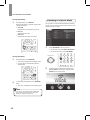
Listening to Internet Radio
To Play Repeatedly
1
During playback, press REPEAT.
Each time the button is pressed, repeat mode
changes as follows:
•• RPT ONE
Repeats the currently playing music file.
You can listen to Internet radio broadcasts provided by
vTuner. You can control the internet radio with the menu
displayed on the TV screen.
•• RPT ALL
Repeats all music files.
•• RPT FLDl
Repeats all music files in the folder.
1
Select NETWORK as an input source.
•• On the main unit, rotate INPUT SELECTOR.
•• On the remote control, press NETWORK.
INPUT SELECTOR
To Play Randomly
1
During playback, press RANDOM.
•• “SFL ON” is displayed on the display panel.
•• All music files in the folder are played in
random order.
2
2
To cancel random playback, press RANDOM
again.
•• “SFL OFF” is displayed on the display panel.
Note
•• You can only use the skip mode, repeat mode
and random mode when playing music files
stored on a USB memory device.
32
When the image is displayed as below, select
Internet Radio on the screen, and then press
ENTER on the remote control.
Operating Your System
Listening to Music from the
Media Server
Select the desired category by pressing
and , then press ENTER on the remote
control.
You can play music files stored on a computer (media
server) connected to this receiver via a wired or wireless
network. You can share the music files easily by using
Windows Media Player 11 or later versions.
Configuring the Windows Media Player
On Windows Media Player 11 version
1
2
3
4
5
Note
•• To use this function, the unit should be connected
to the internet. Refer to “Network Settings” on
page 49 for details.
•• The service may be discontinued without notice.
•• You may not be able to receive some internet
radio stations.
Run the Windows Media Player 11 version on
your computer.
Click the “Library” tab in the menu bar, and then
select “Media Sharing”.
In the “Media Sharing” dialog box, select the
“Share my media” check box, and then click
“OK”.
Select this receiver in the list of devices, and
then click “Allow”.
Click “OK” to close the dialog box.
On Windows Media Player 12 version
1
Run the Windows Media Player 12 version on
your computer.
2
3
Click “Stream” at the top of the player.
4
Select “Local Network” next to Show devices on
if it is not already selected.
5
Click “OK” to close the dialog box.
Click “Turn on media streaming” when it appears
in the next window.
Note
•• Windows Media Player 11 and 12 versions can
be downloaded for free from the Microsoft web
site.
•• If the firewall restricts access, Windows Media
Player 11 and 12 cannot be configured.
33
English
3
R-807 Network AV Receiver
Listening to Music from the Media Server
1
2
5
Start your computer.
Repeat step 3 above until the desired music file
is selected.
The playback functions are the same as those
for USB. Refer to ** for details on playback.
Select NETWORK as an input source.
•• On the main unit, rotate INPUT SELECTOR.
•• On the remote control, press NETWORK.
Using the Sherwood Remote
Application
INPUT SELECTOR
Preparing for the Application
Setting the Network on the System
1
3
Select NETWORK as an input source.
•• On the main unit, rotate INPUT SELECTOR.
•• On the remote control, press NETWORK.
Select Media Server on the screen, and then
press ENTER on the remote control.
INPUT SELECTOR
2
4
Press SETUP on the remote control.
Select the desired category by pressing and ,
then press ENTER on the remote control.
3
Tap Hotspot & Wi-Fi Direct > Soft Wi-Fi
hotspot or Wi-Fi direct.
Note
•• Wi-Fi hotspot is enabled as a default connection
setting.
34
Operating Your System
1
2
3
4
5
Visit Play Store on your Android Smartphone.
Or visit AppStore on your iPhone.
Search for Sherwood Remote.
Download and install the application on your
phone.
Open the application.
Tap Select Product and R-807.
Using the Application
The Sherwood Remote application helps you to control
the main unit remotely by allowing you to select input
source, to set a surround mode, to control Room2, and
use Wiink.
1
2
Open the Sherwood Remote application.
When the product search window is activated,
select and tap R-807. Then, you can use your
smartphone as a remote control for the main
unit.
Connecting Your Phone with the System
•• On a Android phone
1 Go to Wireless & networks settings in your
Android smartphone.
2
3
Enable Wi-Fi direct or Portable Wi-Fi hotspot.
•• When you connect your phone with the main
unit using a Wi-Fi hotspot, you should enter
the password (1234567890) for the system
connection.
Go to Wi-Fi settings to select and tap R-807 and
Connect.
Note
•• When Ethernet is not connected to the main unit,
you cannot use Wi-Fi connection even though
Wi-Fi hotspot is enabled on your phone.
Note
When a network error occurs, the following screen
will pop up.
•• On an iPhone
1 Go to Wi-Fi hotspot settings to select and tap
R-807.
•• Select Product: Check your smartphone network
connection, and select R-807 again.
•• Demo Mode: Uses the application in Demo
Mode.
•• Retry: Tries to open the application again.
35
English
Installing the Application on Your Phone
R-807 Network AV Receiver
Overview of the Main Screen
Using Direct AV
8
1
1
2
2
3
4
Tap Wiink at the bottom of the phone screen.
Or tap INPUT SELECT and select and tap
NETWORK.
Tap Direct AV.
7
5
No.
36
On Direct AV, you can listen to songs, watch videos,
and view photos stored on your Android phone or
iPhone.
6
Description
1
Turns on or off the main unit
•• To activates the function, you should set
N.S.C to ON. If you set the function on,
the power consumption may increase.
2
Selected input source
Surround mode
3
Volume control bar
4
Selects input source
5
Selects surround mode
6
Controls Room2
7
Wiink
(Direct AV, Internet Radio, Media Server)
8
Settings
3
Tap Audio to listen to the songs stored on your
phone.
Tap Video to watch video stored on your phone.
Tap Photo to view photos stored on your phone.
•• iOS
Operating Your System
Watching Videos on Your Smartphone
•• Android
1
You can select a song on the song list and play it over
the main unit.
1
8
2
3
7
6
5
4
No.
7
6
2
3
4
Listening to Songs on Your Smartphone
English
You can select a video on the video file list and enjoy it
on the main unit.
5
No.
Description
1
Moves to the previous menu
•• This menu is not displayed on the Android
smartphone.
2
Plays or pauses a video
3
Moves to a previous video
4
Volume control bar
5
Moves to the next video
6
Controls display size
7
Progress bar
Description
1
Moves to the previous menu
•• This menu is not displayed on Android
smartphone.
2
Plays or pauses a song
3
Plays a previous song
4
Sets shuffle function
5
Volume control bar
6
Sets the repeat function
(Repeat for all song or one song)
7
Plays the next song
8
Progress bar
37
R-807 Network AV Receiver
Viewing Photos on Your Smartphone
Using Internet Radio and Media Server
You can view photos as a slideshow and set the
slideshow transition time at 10, 20, or 30 seconds.
You can use your smartphone as a remote controller for
Internet Radio and Media Server.
1
2
1
2
No.
Tap Wiink at the bottom of the phone screen.
Tap Internet Radio or Media Server.
3
Description
1
Moves to the previous menu
•• This menu is not displayed on the Android
smartphone.
2
Starts the photo slideshow.
3
Sets the slideshow transition time.
1
2
6
5
4
3
No.
38
Description
1
Moves to the previous menu
•• This menu is not displayed on the Android
smartphone.
2
Turns off the main unit.
3
Volume control bar.
4
Returns to the previous menu.
5
Selects or confirms a broadcast in Internet
Radio and Media server.
6
Moves to the settings menu.
Operating Your System
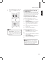
Auto Tuning
1
Press TUNE + or TUNE - for more than
2 seconds.
Manual Presetting
1
Tune to the desired station with auto or manual
tuning.
2
Press ENTER/MEMO.
3
Select a desired preset number (1~30) by
pressing TUNE + or TUNE -.
English
Listening to FM Radio
•• A preset number blinks.
•• The tuner keeps searching until a station with
strong signal strength is found. The display
shows the tuned frequency.
•• If the found station is not the desired one,
simply repeat this operation.
•• Stations with weak signal strength are
skipped during auto tuning.
•• A station has now been stored in the memory.
•• A stored station is erased from the memory
by storing another station in its place.
Manual Tuning
1
Press TUNE + or TUNE - repeatedly until the
desired station is found.
4
Press ENTER/MEMO again to confirm your
selection.
•• The station has now been stored in the
memory.
•• A stored station is erased from the memory
by storing another station in its place.
5
Repeat the above steps 1 - 4 to store another
station.
39
R-807 Network AV Receiver
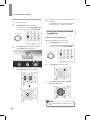
Auto Presetting
RDS Tuning
1
RDS (Radio Data System) is a way of sending
information signals along with transmitter signals.
Your tuner is capable of translating these signals and
displaying the information.
These codes contain the following information:
Program Service name (PS), A list of Program Types
(PTY), Traffic Announcement (TA), Radio Text (RT).
Press and hold down ENTER/MEMO for more
than 2 seconds.
•• “AUTO MEMORY” blinks and the main unit
begins to preset stations with strong signals.
•• Up to 30 FM stations may be stored.
•• To stop auto presetting, press ENTER/MEMO
again.
Note
•• In some countries, RDS tuner function may not
be available.
PTY search
Use this function to automatically search and receive
stations broadcasting a desired type of program.
1
In the FM mode, select the PTY search mode in
the following order:
•• “PTY SEARCH (PTY NAME)” is displayed.
Note
•• FM stations with weak signal strength cannot be
stored to memory.
Tuning in to Preset Stations
1
2
Select FM TUNER as the input source.
Select a desired preset number by pressing
PRESET - or PRESET +.
2
Press or and ENTER/MEMO to select a
program type.
•• Each time these buttons are pressed, one of
29 different types of programs is selected.
(NEWS, AFFAIRS, INFO, SPORT, EDUCATE,
DRAMA, CULTURE, SCIENCE, VARIED,
POP M, ROCK M, EASY M, LIGHT M,
CLASSICS, OTHER M, WEATHER,
FINANCE, CHILDREN, SOCIAL, RELIGION,
PHONE IN, TRAVEL, LEISURE, JAZZ,
COUNTRY, NATION M, OLDIES, FOLK M,
DOCUMENT)
•• When “PTY SEARCH (PTY NAME)” is not
displayed, repeat from step 1.
40
Operating Your System
Recording
3
While a desired program type is displayed:
•• The tuner automatically seeks a station
offering PTY services.
•• If no station is found, “NO PTY” is displayed.
Displaying RDS information
1
Press DISPLAY.
•• The receiver’s volume, Audio parameters (the tone
controls, for example), and surround effects have no
effect on the recorded signal.
•• Some digital sources are copy-protected, and can
only be recorded in analog.
•• Some video sources are copy-protected. These
cannot be recorded.
1
•• Each time this button is pressed, display mode
changes in the following order:
Function Surround Mode Volume Radio
Text(RT) Program Service Name(PS) Program
Type (PTY) Frequency
•• Program Service Name(PS)
The name of the radio station.
•• Program Type(PTY)
This indicates the kind of program currently being
broadcast.
•• Radio Text(RT)
Messages sent by the radio station. For example, a
talk show radio station may provide a phone number
as RT.
•• If signals are too weak or no RDS service is
available, “NO NAME”, “NO PTY” or “NO TEXT” will
be displayed.
English
You can make an audio or a video recording from
the built-in tuner, or from an audio or video source
connected to the receiver (such as a CD player or
TV). Keep in mind you can’t make a digital recording
from an analog source or vice-versa, so make sure
the components you are recording to/from are hooked
up in the same way. (For details on connection, see
“Connecting Playback Components” on page 17.)
2
3
Select the desired recording source.
Start recording on the component.
Start play on the desired input.
•• The audio and video signals from the desired
input will be dubbed on the recorder and you
can enjoy them on the TV set and from the
speakers.
Note
•• The volume and tone (bass and treble) settings
have no effect on the recording signals.
•• When recording the analog signals from CD,
AUX, F.AUX etc., be sure to select the analog
input.
41
Customizing Settings
Setting the System
You can program additional sound settings.
5
1
Press SETUP.
2
Press or to select a main menu.
6
Press or to set a value.
3
Press ENTER/MEMO to confirm.
7
Press ENTER/MEMO to confirm.
Press ENTER/MEMO to confirm the selected
setting.
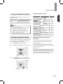
•• To return to the previous menu, press
RETURN.
•• To exit the menu, press SETUP again.
4
42
Press or to select an option.
Customizing Settings
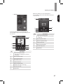
Main Menu
1. SYS SET
2. SPK SET
Sub Menu
Go to Page
5. MLT. RM
Description
AMP
44
Assigns the power amplifier.
A.P.C.
44
Automatic Power Control.
N.S.C.
44
Sets the standby time for the network.
A. SETUP
44
Automatically optimizes the speaker settings.
SPK SET
46
Sets the speaker system.
X.OVER
46
Sets the crossover frequency.
DISTANCE
46
Sets the speaker distance.
CH.LEVEL
46
Sets the current channel levels.
HDMI
47
Sets the connected HDMI input source.
CEC
47
Allows input selection of the main unit to be interlocked
with the operation of the connected components.
H.GAIN
47
Sets the front height channel level.
PNRM
47
Sets to broaden the width of the front stereo image when
using the Dolby Pro Logic IIx Music listening mode.
C.WIDTH
47
Sets the center image so it may be heard only from the
center speaker.
DIEMN
47
Sets the sound field either towards the front or towards
the rear.
C.IMG
47
Sets the center image.
DRC
48
Controls the dynamic range for movie soundtracks
optimized for Dolby Digital, DTS, Dolby Digital Plus and
Dolby TrueHD.
TONE
48
Sets the tone (bass and treble) as desired.
S.DLY
48
Adjust the time delay of audio signals to synchronize the
sound with the picture.
LFE
48
Sets the front height channel level.
Z2
49
Sets to enable or disable the Room2 function.
3. HDMI SET
4. PARAMTR
English
Setting Options Overview
43
R-807 Network AV Receiver
Setting the System Setup
AMP Assign
The surround back channels’ power amplifier can drive
surround back speakers, front height speakers, and
the ROOM 2 speakers. Depending on the purpose of
the speakers, you should assign the power amplifier
accordingly. For details, see “Connecting Speakers” on
page 13 and “Connecting Multi-Room” on page 23.
Menu item
Description
Surround Back
Drives the surround back speakers
when connecting the SURROUND
BACK channels to them.
Front Height
Drives the front height speakers
for Dolby Pro Logic IIz playback.
Room2
Drives the ROOM 2 speakers for
ROOM 2 playback.
Automatic Power Control
Setting the Speaker Setup
After you have installed this receiver and connected
all the components, you should adjust the speaker
settings for the optimum sound acoustics according to
your environment and speaker layout. Whenever you
change speakers, speaker positions, or the layout of
your listening environment, you should also adjust the
speaker settings, too.
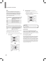
Auto Setup
Auto Setup lets you avoid the more difficult listeningbased speaker setup and achieve good surround
sound automatically. Auto Setup provides the optimum
listening environment for the listening position in your
room. When performing the Auto Setup procedure,
you do not need to perform the Speaker Configuration,
Speaker Crossover, Speaker Distance and Channel
Level setup procedures.
1
•• If your subwoofer has a volume control and
crossover frequency, set the volume halfway
and set the crossover frequency to the
maximum or the low pass filter off.
You can set the standby time for the system to be
turned off. The default setting value is 4H.
Network Standby Control
You can set whether the main unit can be turned on
from other network devices.
Menu item
Description
ON
Enables the network standby
function.
OFF
Disables the network standby
function.
44
Check that the speakers are firmly connected to
this receiver.
2
Connect the supplied microphone to the SETUP
MIC jack on the front panel.
Customizing Settings
Caution
3
English
•• Since the microphone for Auto Setup is designed
exclusively for this receiver, do not use a
microphone other than the one supplied with this
receiver.
Place the microphone on a flat level surface at
the listening position.
•• If possible, use a tripod or to fix the
microphone at the same height as your
ears would be when you are seated in your
listening position.
6
•• The results are memorized and the Speaker
Setup menu is displayed.
•• When is pressed to select “CANCEL”, the
results are not memorized.
•• Ensure there are no obstacles between the
speakers and the microphone.
4
Press to memorize the results.
•• Check the results on each setup menu
(“Speaker Config”, “Speaker Crossover”,
“Speaker Distance” and “Channel Level”
menu on page 46).
Press or to select the Auto Setup, and then
press button.
7
Disconnect the microphone after you have
completed the auto setup procedure.
Caution
•• Because the test tones are loud, ensure there are
no infants or young children in the room.
5
Press to start the auto setup procedure.
•• Loud test tones are output played
successively and when the auto
setup procedure has been completed,
“COMPLETED” will be displayed.
•• To stop the auto setup procedure while
performing it, press .
•• If there is a problem with speaker or
microphone connection, an error message will
be displayed. In this case, turn off the power,
check the connection and then retry the auto
setup procedure.
Note
•• For best results, ensure the room is as quiet as
possible during the auto setup procedure. If there
is too much ambient noise, the results may not
be satisfactory.
•• If the results are not satisfactory, you can retry
the auto setup procedure or personalize your
speaker setup and channel level setup by
choosing the settings manually. For details, see
“Speaker Config”, “Speaker Crossover”, “Speaker
Distance” and “Channel Level” procedure on
page 46.
45
R-807 Network AV Receiver
Speaker Setup
Speaker Distance
There are several ways you can use the speaker
channels with the main unit. In addition to a normal
home theater setup where they are used for the front
height speakers, they can be used as an independent
speaker system in another room.
•• Select the desired unit (Meter or Feet) before setting
the speaker distance. Once a unit is selected, the
distances are automatically converted to the selected
unit.
•• Select the desired speaker, and then press to
enter its setting menu.
Menu item
Description
Yes/No
Selects the desired item
depending on whether the
speakers are connected or not.
2 Channel/
1 Channel (Left)
Selects the desired item
depending on the number of
speakers connected to Surround
Back/Multi channels.
Note
•• When a speaker is not set to “NO”, you need
to set their distances from listening position
and crossover frequencies according to their
frequency characteristics. For details, see
“Speaker Crossover” on page 46 and “Speaker
Distance” on page 46.
•• When the “SR” is set to “NO”, “SB” cannot be set
to “2 Channel” or “1 Channel (Left)”.
•• When the surround back channels’ power
amplifier is assigned to “Room 2”, the “SB”
cannot be selected. For details, see “AMP
Assign” on page 44.
Speaker Crossover
You can set the crossover frequency according to the
frequency characteristics of the connected speakers.
For details on the frequency characteristics, refer to the
operating instructions of the speakers.
•• You can select the crossover frequency among Full
Range, 40 Hz, 60 Hz, 80 Hz, 100 Hz, 120 Hz, 150 Hz,
200 Hz, and 250 Hz. The default setting is 100 Hz.
•• Select “Full Range” when the selected speaker can
fully reproduce frequencies below 40 Hz.
Note
•• You cannot select the subwoofer and the speaker
set to “NO”.
•• If the frequency range of your speaker is
100 Hz~20 kHz, the crossover frequency should
be set to 100 Hz or slightly higher. For details,
refer to the operating instructions of the speakers
to be connected.
•• Frequencies below the crossover frequency are
output from the subwoofer or the speakers when
they are set to “Full Range” (when not using a
subwoofer).
46
•• You can set the distance within the range of 0.1 ~
9.0 meters in 0.1 meter intervals (or 0.5 ~ 30.0 feet
in 0.5 foot intervals).
•• About the speaker distance
When enjoying multi-channel surround playback with
sources such as Dolby Digital and DTS sources, etc.,
it is ideal that the center, surround, and surround
back speakers should be the same distance from
the main listening position as the front speakers.
By entering the distance between the listening
position and each speaker, the delay times of center,
surround and surround back speakers, etc. are
automatically adjusted to create an ideal listening
environment virtually as if they were in their ideal
locations.
Speaker Channel Level
You can adjust the current channel levels as desired.
After adjusting each channel level with the test tone,
adjust the channel levels either according to the program
sources or to suit your tastes. For details, see “Adjusting
each channel level with test tone” on page 30.
Customizing Settings
Setting the Surround
Parameter Setup
HDMI
You can specifies the routing of the HDMI audio signal
from the system or through to a TV or flat screen TV.
The HDMI connection can carry uncompressed digital
video signals and digital audio signals. Depending on
whether the digital audio signals input into the HDMI
IN are output from the HDMI MONITOR OUT of the
main unit or not, you should set the HDMI Audio Output
correctly.
Menu item
You can adjust the front height channel level as desired
(This setting is valid only when listening in Dolby Pro
Logic IIz mode).
Menu item
AMP
TV
Enables HDMI digital audio signals
output from the HDMI MONITOR
OUT of the main unit. Then,
these signals are heard from the
speakers of your TV.
Note
•• If the HDMI Audio Output is set to “TV”, no sound
will be heard from the speakers connected to this
receiver (except ROOM 2 speakers) even if an
input source is selected.
CEC Control
The CEC Control function allows input selection of the
main unit to be interlocked with the operation of the
connected components.
Description
On
Enables the CEC Control function.
Off
Disables the CEC Control function.
Description
L : Low
Decreases the front height
channel level.
M : Mid
Outputs the front height channel
sound with standard sound volume
level.
H : High
Increases the front height channel
level.
Description
Disables HDMI digital audio
signals output from the HDMI
MONITOR OUT of this main unit.
Then, these signals are heard
from the speakers connected to
this receiver.
Menu item
Height Gain
PANORAMA
You can extend the front stereo image to include the
surround speakers for an exciting effect with side wall
imaging.
Menu item
Description
On
Enables the panorama effect.
Off
Disables the panorama effect.
Center Width
This adjusts the center image so it may be heard only
from the center speaker, only from the left or right
speakers as a phantom image, or from all three front
speakers to varying degrees. The control can be set in
8 steps from 0 to 7.
Dimension
This function gradually adjusts the sound field either
towards the front or towards the rear.
The control can be set in 7 steps from -3 to +3.
Center Image
When one of the Neo:6 is enabled, you can adjust
the level of the center image so it may be heard from
the center speaker more The level can be adjusted in
11 steps from 1 to 10.
47
English
Setting the HDMI Setup
R-807 Network AV Receiver
2
DRC
This function compresses the dynamic range of
previously specified parts of the Dolby Digital, Dolby
TrueHD or DTS sound track (with extremely high
volume) to minimize the difference in volume between
the specified and non-specified parts. This makes
it easier to hear the full sound track when watching
movies at night at low levels.
Menu item
Adjust the selected tone as desired by
pressing or .
•• The tone level can be adjusted within the
range of -10 ~ +10 dB.
•• It is recommended the bass and treble to be
adjusted to 0 dB (flat level).
Description
Auto
Adjusts the dynamic range
compression automatically (Dolby
TrueHD only).
Off
Turns off the DRC function.
Mid
Sets to Mid compression.
Max
Sets to Max compression.
Tone
You can adjust the tone (bass and treble) as desired.
Menu item
Description
On
Adjusts the tone for your taste.
Off
Listens to a program source
without the tone effect.
Adjusting the tone (Bass and Treble)
You can adjust the tone if the Tone is set to “ON”.
1
Select the desired tone by pressing or , and
then press .
Caution
•• Extreme settings at high volume may damage
your speakers.
Sound Delay
Some monitors have a slight delay during video
playback, so the soundtrack will be slightly out of sync
with the picture. By slightly increasing delay, you can
sync the sound to the video. The delay can be adjusted
within the range of 0 ms ~ 90 ms.
Low Frequency Effect
This channel reproduces low-frequency bass signals
and has a frequency range from 20 Hz to 120 Hz. This
channel is added to the channels for all bands with
Dolby Digital or DTS to enhance low frequency audio
effects. When the receiver is connected to a subwoofer,
you can produce LFE (low-frequency effect) channel
sounds and reinforce the bass parts of other channels.
The Low Frequency Effect can be disabled and set in
4 steps from -20 dB to 0 dB.
48
Customizing Settings
In addition to your main room, you can also enjoy
playback in Room2.
Menu item
Network Settings Overview
Main Menu
Description
On
Turns on the Room2 function.
Off
Turns off the Room2 function.
NETWORK
CONNECT
Sub Menu
Soft AP
Direct hotspot
AV Set
Wi-Fi direct
Wired
Note
•• When Room2 is set to “OFF”, the input and the
volume cannot be selected.
•• When you do not use the Room2 function, set
the Room2 to “OFF” to save electricity.
•• The digital signals (including signals from the
USB IN) cannot be output to the other rooms,
meaning no playback in Room 2.
To listen to Internet radio stations or music files stored
on your computer via a wired/wireless network, you
should configure network settings first.
1
2
49
49
Ethernet
50
Ethernet
Configuration
50
AP Name
50
Resolution
50
Display size
50
Factory Setting
50
Network Information
50
Passcode Information
50
OTHER
INFORMATION
Setting the Network Setup
Go to Page
English
Setting the Multi Room Setup
Setting the Direct Wireless Network
Connection
You can connect the main unit with a mobile device
wirelessly through Soft AP hotspot or Wi-Fi direct.
Press SETUP on the remote control.
Soft AP hotspot
Press or to navigate up or down the menu.
When you enable Soft AP hotspot, you can use the
main unit as a wireless access point. It provides internet
access to network devices.
Wi-Fi direct
Wi-Fi Direct is a standard that allows Wi-Fi devices to
connect to the main unit without the need for a wireless
access point. When you enable Wi-Fi Direct, you can
directly transfer data between Wi-Fi direct devices and
the main unit without the need for full setup.
3
Press ENTER to confirm the desired menu.
Press RETURN to move to the previous menu.
49
R-807 Network AV Receiver
Setting the Wired Network Connection
Before you setup the connection, check that the LAN
cable is connected to the LAN/ETHERNET connector
properly and securely. For details, see “Connecting to
LAN cable” on page 20.
Setting Other Network Options
Menu item
Description
AP Name
Views and changes the name of
the unit displayed on the network.
Ethernet
Resolution
You can enable and set the Ethernet connection
automatically on the main unit.
Sets the resolution of the video
output.
Display size
Adjusts the screen display size
manually.
Factory Setting
Resets all the settings to the
factory default.
Ethernet Configuration
You can set the Ethernet connection settings manually.
Menu item
Description
Ethernet Device
Inputs an Ethernet device name.
Viewing the Network Information
Connection Type
Sets the connection type as DHCP
or Static IP.
Network Information
IP Address
Inputs IP Address.
Netmask
Inputs subnet mask when the
DHCP function is disabled.
DNS address
Inputs DNS address when the
DHCP function is disabled.
Default Router
Inputs Default Router when the
DHCP function is disabled.
Note
•• When you set DHCP as a connection type, you
do not need to set the IP Address, Netmask, or
DNS address etc.
•• When you set Static IP as a connection type, you
should set the network connection manually by
entering the IP Address, etc. In this case, some
knowledge of networks is required. If you do not
understand internet connections, contact your
internet service provider.
50
You can view the detailed information of a connected
network.
Passcode Information
You can view and change the passcode of the main
unit. When you use the main unit for the first time, you
should input this passcode when you enable Soft AP
hotspot and try to connect the mobile device to the main
unit.
Troubleshooting
If you experience any of the following difficulties while using the system, use this troubleshooting guide to help
remedy the problem before requesting servicing. Should any problem persist, consult your nearest authorized dealer
or authorized independent company.
English
If the unit does not operate normally due to external influence such as static electricity, disconnect the power plug
from the outlet and insert again to return to normal operating conditions.
GENERAL
Problem
Remedy
The power does not turn on.
•• Disconnect the power plug from the outlet, and connect again.
The system suddenly turns
off.
•• After about a minute (you won’t be able to turn the main unit on during this time),
turn the system back on. If the message persists, call an authorized independent
service company.
No sound is heard after a
function is selected.
•• Make sure the component is connected correctly.
(See “Connections” on page 10.)
•• Press MUTE to restore the sound.
Can’t operate the remote
control.
•• Replace the batteries. (See page 6.)
•• Operate within 7 m, and 30° of the remote sensor.
•• Remove any obstacles, or operate from another position.
•• Avoid exposing the remote sensor on the front panel to direct light.
The display is dark or off.
•• Press DIMMER on the control repeatedly to return to the default setting.
SOUND
Problem
There is no sound from the
selected component.
Remedy
•• Check that the component is connected correctly to the audio input jacks of
components.
•• Ensure that the cords are fully inserted into the jacks on both the component
and the main unit.
•• Ensure that the component is selected correctly.
•• Ensure that the equipment is connected correctly to the HDMI jack for that
equipment.
•• Depending on the playback equipment, you may need to adjust the HDMI
setting of the equipment. Refer to the operating instructions supplied with the
equipment.
•• Be sure to use a High Speed HDMI cable when you view images or listen to
sound, especially for the 1080p, Deep Color (Deep Colour) or 3D transmission.
•• Audio signals (format, sampling frequency, bit length, etc.) transmitted from an
HDMI jack may be suppressed by the connected equipment. Check the setup of
the connected equipment if the image is poor or the sound does not come out of
the equipment connected via the HDMI cable.
•• When the connected equipment is not compatible with copyright protection
technology (HDCP), the image and/or the sound from the HDMI TV OUT jack
may be distorted or may not be output. If this is the case, check the specification
of the connected equipment.
51
R-807 Network AV Receiver
Problem
Remedy
Sound is interrupted or there
is noise.
•• Check the output audio formats support system.
•• Check that the speakers and equipment are connected securely.
•• Move your audio equipment away from the TV.
•• The plugs and jacks are dirty. Wipe them with a cloth slightly moistened with
alcohol.
No sound is heard or there
is noise when software with
DTS is played back.
•• Set the digital volume level of the system to full, or to the neutral position.
•• Ensure the main unit's settings are correct and/or the DTS signal out is on.
Refer to the instruction manual supplied with the DVD player.
The left and right sounds are
unbalanced or reversed.
•• Ensure that the speakers and equipment are connected correctly and securely.
•• Adjust the sound level parameters using the Speaker Settings menu.
Recording cannot be carried
out.
•• Ensure that the equipment is connected correctly.
•• Select the source equipment using the input buttons (See page 26).
•• Audio input signals via HDMI IN and DIGITAL IN jacks cannot be recorded.
•• Copyright protection to prevent recording is contained in the sources. In this
case, you may not be able to record from the sources.
A test tone is not produced
from the speakers.
•• The speaker cords may not be connected securely. Check to see if they are
connected securely and cannot be disconnected by pulling on them slightly.
•• The speaker cords may have a short-circuit problem.
A test tone is heard from a
different speaker than the
speaker displayed on the TV
screen.
•• The speaker pattern set up is incorrect. Make sure that the speaker connections
and the speaker pattern match correctly.
No sound, or sound suddenly
ceases.
•• If you’ve made separate connections for audio, make sure you have assigned
the analog/digital jack(s) to the corresponding HDMI input for the component.
•• Check the audio output settings of the source component.
•• If the component is a DVI device, use a separate connection for the audio.
VIDEO
Symptom
52
Remedy
No image appears on the TV.
•• Select the appropriate input using the input buttons.
•• Set your TV to the appropriate input mode.
•• Move your audio equipment away from the TV.
•• Assign the component video input correctly.
•• Make sure that cables are correctly and securely connected to equipment.
Recording cannot be carried
out.
•• Check that the equipment is connected correctly.
•• Select the source equipment using the input buttons (See page 26).
•• Video input signals via HDMI IN and COMPONENT VIDEO IN jacks cannot be
recorded.
•• Copyright protection to prevent recording is contained in the sources. In this
case, you may not be able to record from the sources.
No picture or sound.
•• If the problem still persists when connecting your HDMI component directly
to your monitor, consult the component or monitor manual or contact the
manufacturer for support.
Troubleshooting
No picture.
Remedy
•• Depending on the output settings of the source component, the video format
may not be displayed. Change the output settings of the source, or connect your
source component directly to TV using the component or composite video jacks.
•• This system is HDCP-compatible. Check that the components you are
connecting are also HDCP-compatible. If they are not, please connect your
source component directly to TV using the component or composite video jacks.
•• Some source components will not work with the main unit (even if it is
HDCP‑compatible). In this case, connect your source component directly to TV
using the component or composite video jacks.
•• If video images do not appear on your TV or flat screen TV, try adjusting the
resolution, DeepColor or other setting for your component.
•• To output signals in DeepColor, use an HDMI cable (High Speed HDMITM
Cable) to connect the main unit to a component or TV with the DeepColor
feature.
English
Symptom
USB device
Symptom
Remedy
There is noise, skipping, or
distorted sound.
•• Turn off the receiver and reconnect the USB device, then turn on the main unit.
•• The music data itself contains noise, or the sound is distorted.
The USB device is not
recognized.
•• Turn off the main unit, then disconnect the USB device. Turn on the main unit
again and reconnect the USB device.
•• Connect the supported USB device (See page 31).
•• The USB device does not work properly. Refer to the USB device operating
instructions on how to deal with this problem.
Playback does not start.
•• Turn off the main unit and reconnect the USB device, then turn on the main unit.
•• Connect the supported USB device (See page 31).
The USB device cannot be
connected into the (USB)
port.
•• The USB device is being inserted upside down. Connect the USB device in the
correct orientation.
53
R-807 Network AV Receiver
NETWORK CONNECTION
Symptom
Remedy
The main unit cannot
connect to the WPS via a
wireless LAN connection.
•• You cannot connect to a network using WPS when your access point is set to
WEP. Set up your network after searching the access point using the access
point scan.
The receiver cannot connect
to the network.
•• Check the network status.
•• When the system is connected through a wireless network, move the main unit
and the wireless LAN router/access point closer to each other and do the setup
again.
•• Check the settings of the wireless LAN router/access point and do the
setup again. For details on the settings of the devices, refer to the operating
instructions of the devices.
•• Make sure that you use a wireless LAN router/access point.
•• Wireless networks are influenced by electromagnetic radiation emitted by
microwave ovens and other devices. Move the main unit away from these
devices
Cannot select the Network
Settings menu.
•• Wait for a few moments after you have turned on the main unit, and then select
the Network Settings menu again.
Important Information Regarding the HDMI Connection
Some HDMI signals cannot be routed through this system. (This depends on the HDMI-equipped component you are
connecting. Check with the manufacturer for HDMI compatibility information.)
If you cannot receive HDMI signals properly through the main unit (from your component), please try the following
configuration when connecting.
54
Additional Information
English
Specifications
Audio Section
Multichannel power
75 W per channel, two channels driven @ 6 ohms,
20 Hz – 20 kHz, <0.1 % THD; 100 W per channel,
two channels driven @ 6 ohms, 1 kHz, <1 % THD
Input sensitivity/impedance
200 mV/47k ohms
Signal-to-noise ratio (IHF-A)
95 dB
Surround system adjacent-channel separation
Dolby Pro Logic/PLII: 40 dB
Dolby Digital: 55 dB
DTS: 55 dB
Frequency response
10Hz – 100kHz: ±3 dB
High instantaneous-current capability (HCC)
±25 amps
FM Tuner Section
Frequency range
87.5 – 108.0 MHz
Usable sensitivity IHF
1.3 μV/13.2 dBf
Signal-to-noise ratio (mono/stereo)
65 dB/62 dB
Distortion (mono/stereo)
0.2 %/0.3 %
Stereo separation
35 dB @ 1 kHz
Image rejection
80 dB
IF rejection
80 dB
AM Tuner Section
Frequency range
522 – 1161 kHz
Signal-to-noise ratio
45 dB
Usable sensitivity (loop)
500 μV
Selectivity (±10kHz)
30 dB
IF rejection
80 dB
55
R-807 Network AV Receiver
Video Section
Television format
NTSC/PAL
Input level/impedance
1 Vp-p/75 ohms
Output level/impedance
1 Vp-p/75 ohms
Video frequency response (composite video)
10 Hz – 8 MHz (–3 dB)
HDMI
With 3 D and Deep Color
General Specifications
Power requirement
AC 230 V/50 Hz
Power consumption
<0.5 W (standby), 280 W maximum
Dimensions (W x H x D)
17.12" x 4.9" x 13" (435 mm x 125 mm x 331 mm)
Weight
22.9 lb (10.4 kg)
Trademarks and Licenses
This system incorporates a sophisticated Digital Signal Processor that allows you to create optimum sound quality
and sound atmosphere in your personal Home Theater.
DTS-HD Master Audio
Manufactured under license under U.S. Patent Nos:
5,956,674; 5,974,380; 6,226,616; 6,487,535; 7,212,872;
7,333,929; 7,392,195; 7,272,567 & other U.S. and
worldwide patents issued & pending. DTS-HD, the
Symbol, & DTS-HD and the Symbol together are
registered trademarks & DTS-HD Master Audio is a
trademark of DTS, Inc. Product includes software.
© DTS, Inc. All Rights Reserved.
Dolby TrueHD
Manufactured under license from Dolby Laboratories.
Dolby and double-D symbol are trademarks of Dolby
Laboratories.
56
HDMI
HDMI, the HDMI Logo, and High-Definition Multimedia
Interface are trademarks or registered trademarks of
HDMI Licensing LLC in the United States and other
countries.
R-807
Network AV Receiver
Récepteur réseau AV
Receptor A/V con conexión de red
Netzwerk-AV-Receiver
Сетевой AV-ресивер
5707-00000-795-0S
Printed in China
Imprimé en Chine
Impreso en China
Gedruckt in China
Отпечатано в Китае