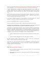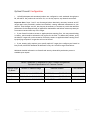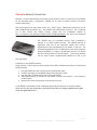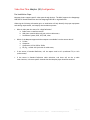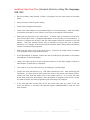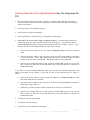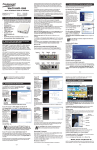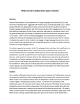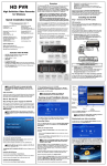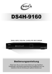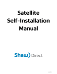
1
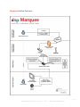
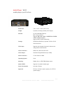
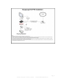
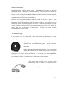
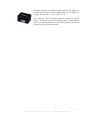
Technical Guide
Marquee W610 Media Player
November 19, 2010
Marquee W610 Technical Guide - Version 1.0 – 111610
DMX ©2010 All Rights Reserved
Page | 1
Table of contents
Marquee Introduction ............................................................................................ 3
Marquee Solution Overview ..................................................................................... 4
Media Player – W610 ............................................................................................. 5
media player specifications .................................................................................. 5
installation of W610 player .................................................................................. 6
step by step instructions....................................................................... 7
prior to leaving client premise................................................................ 8
Network Configuration........................................................................................... 9
Wireless Network Activation and / or Static IP ........................................................... 9
optimal firewall configuration.............................................................................. 10
alternate Network Connection ............................................................................. 11
Video pass-thru adapter (standard) configuration ......................................................... 12
installing video pass-thru (standard definition) using the Hauppauge HVR-1950................... 13
installing video pass-thru (high definition) using the Hauppauge HD-PVR........................... 15
Quick Start Installation of W610 player...................................................................... 18
Audio Visual Best Practices Guide ............................................................................ 19
Troubleshooting ............................................................................................... 20
Tested and Approved for Best Practices .................................................................. 23
Marquee W610 Technical Guide - Version 1.0 – 111610
DMX ©2010 All Rights Reserved
Page | 2
Marquee Introduction
Welcome!
This Marquee Technical Guide has been designed to walk you through the technical
aspects and installation of the Marquee system with the W610 media player - step by step
- giving you the detail and supporting information you will need to perform a standard
installation.
Towards the end of the document, you will find recommendations on how to handle less
ordinary installations. You will also find a one page “Quick Start Installation” guide,
which is included with each player.
Please remember, you may always call DMX customer support at 800–345-5000 for
assistance in all installation matters.
Marquee W610 Technical Guide - Version 1.0 – 111610
DMX ©2010 All Rights Reserved
Page | 3
Marquee Solution Overview
Marquee W610 Technical Guide - Version 1.0 – 111610
DMX ©2010 All Rights Reserved
Page | 4
Media Player – W610
media player specifications
Dimensions
7.56” x 8.27” x 2.44” (W x D x H)
Weight
5 pounds, including external power supply
Network
10/100/1000 Mbps Ethernet
802.11b/g/n wireless
Supports WEP, WPA, WPA2, CIPHER-TKIP & CIPHERCCMP wireless encryption
Supports DHCP & static addressing
Storage
250 GB Hard Disk Drive, Optional 16 GB or 32 GB
Solid State Drive
Video Input
Supports pass-through of external video sources
using optional video encoder
Video Connectors
HDMI, DVI-I (Dual Link) and VGA
Video Output
Standard & High Definitions up to 1080p
Audio Connectors
3.5 mm Stereo or HDMI
Operating System
Linux
Mounting
Rubber feet, or VESA/FDMI display mount
Media CODECs
Supports all standard media types
Power Consumption
Less than 32 watts
Approvals
FCC Part 15 Class A (entire system), UL/CE/TUV
(power supply)
Marquee Technical Guide ‐ Version 6.2.4 – 100610 11Giraffes ©2010 All Rights Reserved Page | 5
installation of W610 player
required tools & equipment
• Ethernet patch cable (for wired configuration)
• HDMI, VGA (DDC2 Recommended) or DVI display cable(s)
• Male 1/8” (3.5mm) cable (for non-HDMI audio)
helpful tools for player configuration and troubleshooting
• Laptop computer
• USB keyboard
• Network cable tester
• label maker (to label any cables that may run a long distance)
• Spare RJ-45 (Ethernet) connectors
• Tie wraps
• Cable cutter
DMX support hours
• M-F 7:30 AM to 7:30 PM, CST
• Saturday 9:00 AM to 6:00 PM, CST
pre installation steps
1. Standard wired or wireless broadband Internet access is required. In addition, HTTP,
HTTPS and SFTP ports (80, 443 and 22, respectively) should be enabled. Specific IP ranges to
configure firewall settings are listed in the Optimal Firewall Configuration section of this
document.
2. Verify displays support Marquee. Most displays on the market today will support Marquee.
If the client has an existing video distribution solution, the below recommendations will help
ensure the monitors take maximum advantage of Marquee:
a. Identify inputs (e.g., HDMI, VGA, DVI) that can / will be used.
b. Determine the location where Marquee player(s) will be installed. Ensure that dedicated
(non-switched) power is present, and that network cabling or wireless coverage is
available.
c. Review the video distribution requirements for distances and numbers of screens.
The distance from the signage player to each monitor, and functionality required, dictates
the type of connection. Distances of less than 100 feet may not need any amplification of
signal and may be able to split signal to up to three monitors using VGA two way splitters and
high quality VGA cables. Review supporting documentation for any solution over three
monitors and or a distance of over 100 feet. Please verify if content is being presented in
landscape or
Marquee Technical Guide ‐ Version 6.2.0 – 090110 11Giraffes ©2010 All Rights Reserved Page | 6 portrait mode, and if live TV or other external video is to be presented on the screens. For
more detailed information on these and other scenarios, consult the current Marquee
Installation Instructions.
3. Out of the box, the W610 defaults to operate from a wired network connection. If
performing a wireless setup, you will need to know the following information in advance of
performing configuration:
–
–
–
–
SSID
Encryption Key Type (e.g., WEP/WPA)
Passphrase type (ASCII/Hex). If this is unknown, and the key contains
only the letters A-F and numbers, it is most likely a Hex key.
Passphrase or Key
After obtaining this information, please follow the instructions later in this document under
Wireless Installations.
4. The default network configuration uses DHCP to acquire a network address. If a static IP
address if preferred or required, follow the instructions later in this document.
step by step instructions
Identify a discreet location for placement of the media player. Ideally, it should have limited
access and be near an existing network port to the Internet. A network/phone closet, manager’s
office or other secure location is recommended. Place the media player in a location near the
dedicated power source, the available network port, and where at least 3” of airflow is
available around the unit. The media player may be mounted on its side if necessary.
Confirm availability of a dedicated (non-switched) power source. The media player receives
content and software updates overnight. It should not be powered by a source that is turned off
at any time.
Note that standard broadband Internet access is required. In addition, HTTP, HTTPS and SFTP
ports (80, 443 and 22, respectively) should be enabled.
Recommended Step – Verify Internet Access: Using a laptop (or other network device), connect
to the existing network and confirm that www.Marquee11.com can be pinged. If it is not
accessible, network connectivity must be corrected prior to proceeding.
Wired - Connect one end of the included Ethernet patch cable to the existing host network port.
Connect the other end of the Ethernet patch cable to the RJ-45 Ethernet port on the rear of the
media player.
Wireless - Connect the wireless antenna to the antenna post on the rear of the media player.
Marquee Technical Guide ‐ Version 6.2.0 – 090110 11Giraffes ©2010 All Rights Reserved Page | 7 Connect the appropriate cables from the video screen to the appropriate connector on the rear
of the media player. The screen should be powered on prior to powering the media player.
If audio is being installed, and HDMI video cables are not being used, connect a male 1/8”
(3.5mm) connector cable (not included) to the GREEN analog audio connector on the rear of
the media player. Connect the other end of this cable to the audio amplifier or display audio
input.
NOTE: The W610 media player defaults to using audio over HDMI. If analog audio is to be used,
this must be communicated when contacting Dealer Support. The player settings will be
remotely changed to output analog audio at this time.
If the player is required to support live video content from an external source (e.g., cable or
satellite TV), please see the required installation steps later in this document.
Connect the included power cable to the rear of the media player.
Connect the other end of the power cable to a dedicated (non-switched) power source.
Unit should power on automatically. If not, press the power button on the front faceplate of the
media player. The screen will be black for about 25 seconds as the player starts.
Upon startup, the media player will display a series of diagnostic messages for approximately
90 seconds. Green Pass messages throughout indicate that the player is successfully installed
and able to communicate with Marquee servers. Any Red Fail messages indicate the location of
a network problem. Note these and provide them to the local network administrator to
troubleshoot. At the conclusion of this diagnostic screen, the image will either:
•
change to a Marquee logo until the client playlist has completed the download process;
or
•
continue to display the Marquee logo until a client playlist is assigned.
Call DMX Customer Support at 800-345-5000 to confirm connectivity, provide serial
number, validate location information and activate player.
Please advise your client that download times will vary substantially, and are based upon the
number of files being downloaded, the type of files (video or image) and the amount of
available bandwidth to the media player.
Prior To Leaving Client Premise
•
Point out location of the serial number, power button, power cord, Internet and cable
connections to the customer.
•
Ensure your customer knows how to contact DMX Customer Service should they experience
any problems.
Marquee Technical Guide ‐ Version 6.2.0 – 090110 11Giraffes ©2010 All Rights Reserved Page | 8 Network Configuration
Wireless Network Activation and / or Static IP
The Marquee media player will automatically connect with Marquee servers using a wired
network. In some installations, you may wish to utilize a wireless network. To do so, perform
the following steps to activate the wireless network on the Marquee media player.
Note: If performing a wireless setup you will need to know the following information in advance
of performing configuration:
–
–
–
–
SSID
Encryption Key Type (e.g., WEP/WPA)
Passphrase type (ASCII/hex). If this is unknown, and the key contains only the letters
A-F and numbers, it is most likely a hex key.
Passphrase or Key
Step By Step Instructions
•
•
•
•
•
•
•
•
•
•
•
Attach a USB keyboard to the player.
Apply power and start the media player.
After the diagnostic screen concludes playback, simultaneously press CTRL – ALT – Q on
the keyboard. Playback will cease for 10 minutes. If you do not complete the following
within 10 minutes, you will need to press CTRL – ALT – Q again to exit playback.
Simultaneously press CTRL – ALT – D on the keyboard. This will bring up the Network
Setup Utility. If during this process the player restarts or covers part of the screen, use
ALT – TAB to view the Network Setup Utility window. To close the Network Setup Utility
without saving changes, simultaneously press CTRL – C.
Proceed with the setup process by entering your selection to each question and pressing
<Enter> to proceed to the next question.
Once all the data has been entered the player will try to connect using the data entered
and display the message “* Reconfiguring network interfaces…”.
When this is completed the IP address will be displayed near the bottom of the window.
If a message is received stating “No DHCPOFFERS received.” Please recheck your
settings, exit the utility and restart the Network Setup Utility to begin again.
Once setup is completed press <enter> as instructed to exit network setup.
Reboot the media player. Upon restart, confirm connectivity and communication with
remote servers using the feedback provided on the Loading Screen.
Should you require assistance, call DMX Customer Service at 800-345-5000.
Marquee Technical Guide ‐ Version 6.2.0 – 090110 11Giraffes ©2010 All Rights Reserved Page | 9 Optimal Firewall Configuration
11Giraffes Marquee and associated products are configured to work outbound through ports
80, 443 and 22. Our products do not listen for, nor do they require, any inbound connections.
1.
Important Note: Steps 2 and 3 are discouraged unless absolutely necessary because such IP
ranges need to be periodically audited and modified, creating additional maintenance to your
network. These changes are rare, but they may be necessary to continue to provide the maximum
performance for the Marquee family of applications. Maintenance and failover events may cause you
to connect to servers within any of the ranges.
If your firewall includes a content or application data scanning filter, this may cause blocking
or latency, which would be indicated in the log files for the filter. To address this problem, verify
the below IP ranges will not be scanned or filtered by content or application data scanning filters
by specifying exception IP ranges that will not be filtered.
2.
If your security policy requires you to specify explicit IP ranges, then configure your firewall to
limit port 80, 443 and 22 destination IP addresses to only the 11Giraffes ranges listed below.
3.
Additional detailed information on firewalls and security vulnerability evaluation process is
available upon request.
Server / Datacenter IP Addresses for Use in Firewall Configurations
Equivalent Specifications in 3 Common Formats
Assigned Range
by Block*
Numeric IP Address Range
Netmask Notation
CIDR Notation
Block 1
216.27.66.144 - 216.27.66.159
216.27.66.144
255.255.255.240 216.27.66.144/28
Block 2
74.213.132.16 - 74.213.132.31
74.213.132.16
255.255.255.240 74.213.132.16/28
Block 3
74.213.132.224 - 74.213.132.239 74.213.132.224
255.255.255.240 74.213.132.224/28
Marquee Technical Guide ‐ Version 6.2.0 – 090110 11Giraffes ©2010 All Rights Reserved Page | 10 Alternate Network Connection
Marquee is a networked solution and requires active internet access. If a network is not available
for the Marquee player, Cradlepoint’s CBA250 can be used to provide cellular over-the-air
wireless networking.
This device supports all major data carriers (e.g., AT&T, Sprint, T-Mobile and Verizon) as well as
USB or PCMCIA-express devices (e.g., the Franklin U301 USB modem via Sprint). For a complete
list of data carriers and express devices, please visit the Cradlepoint website at
http://cradlepoint.com/products/cba250-cellular-broadband-adapter and select the Supported
Devices tab.
The CBA250 may be purchased directly from Cradlepoint’s
website, or via other internet sources. The CBA250 requires an
agreement with one of the supported mobile data carriers.
Agreements are the responsibility of the dealer or end user. We
recommend agreements with a 5 GB monthly limit which should be
enough bandwidth to support the Marquee solution and should
prevent overage charges on the data plans. The average monthly
cost for most carriers is approximately $60.00 for a one or two
year agreement.
Installation of the CBA250 is simple:
Using a laptop, confirm that the wireless data carrier USB or PCMCIA-express device is authorized
and functioning.
1.
2.
3.
4.
Plug the CBA250 into the wall using the included power cable.
Connect the player to the CBA250 using an Ethernet patch cable.
Plug the USB or PCMCIA-express device into the CBA250.
Wait approximately 15 seconds for the CBA250 to access the network. It will display a
network signal.
5. Apply power to the media player and proceed as normal.
If the CBA250 is unavailable, other Cradlepoint devices should function in the same manner.
When selecting one, be certain that it provides IP Pass-Thru (or bridging) capability and, again,
verify the supported devices.
Marquee Technical Guide ‐ Version 6.2.0 – 090110 11Giraffes ©2010 All Rights Reserved Page | 11 Video Pass-Thru Adapter (SD) Configuration
Pre-Installation Steps
Marquee players support specific video pass through devices. The W610 supports the Hauppauge
HVR1950 for standard definition and the Hauppauge HD-PVR for high definition.
Gathering the following information prior to installation will help identify the proper equipment
and cabling requirements, and simplify the installation process:
•
What is video pass-thru source? Is it High Definition?
a. Cable tuner or satellite receiver
b. Wall-plate (coaxial cable wall-jack with no cable tuner)
c. Surveillance system, DVD, VCR, DVR, other
•
Which of the Marquee-supported video outputs are available from the source device?
d. S-Video
e. Composite
f. Component (YCrCb, RGB or YPbPr)
g. RF (e.g., coaxial wall-jack with no cable tuner)
•
If the source is Standard Definition, will the aspect ratio be 4:3 (traditional TV) or 16:9
(wide-screen)?
•
If the source is Standard Definition cable television, and there will not be a cable
tuner/receiver, is there a specific channel that the Marquee player should be tuned to?
Marquee Technical Guide ‐ Version 6.2.0 – 090110 11Giraffes ©2010 All Rights Reserved Page | 12 Installing Video Pass-Thru (Standard Definition) Using The Hauppauge
HVR-1950
•
Run the necessary cable (Coaxial, S-Video or Composite) from the video source to the media
player.
•
Verify the source video using this cabling.
•
Power down the digital media player.
•
Connect the Video Adapter to any available USB port on the media player. Note that ideally
it should be connected to a port where it is not likely to be bumped or disconnected.
•
Determine the connection to the video source. If Coaxial cable (F-Connector) will be used,
then the included S Video / Composite cable adapter is not necessary for this installation. If
S-Video or Composite will be used, then the cable adapter should be connected to the USB
Adaptor. Note that multiple sources may be installed as long as each uses a separate
connection. For example, a cable tuner may be connected using S-Video while a surveillance
camera is connected using Composite.
•
Determine the aspect ratio of the output source. Determine if output source is standard
(4:3), standard (16:9) or high definition (16:9).
•
If the cable adapter is required, connect the mail mini-USB end of the adapter to the female
mini-USB port on the Video Adapter.
•
Connect the video source(s) to their respective connector on the Video Adapter (Coaxial) or
cable adapter (S-Video and/or Composite).
•
Turn power on to (1) the video source(s); (2) display(s); (3) media player.
•
Instruct the client which device (e.g., HVR-1950) connection(s) was / were used during the
installation. If Coaxial cable is used, instruct the client of the source video output channel.
Instruct the client what the aspect ratio of their output source is. It is critical the client
knows which connection (and channel, where applicable) is assigned to each source, as they
will need to identify this when programming the media player for playback.
•
If the video pass-thru content does not fill the entire video zone (e.g. black on the top
and/or the bottom, or the sides), call technical support at 888.825.9496 to resize the video
zone remotely.
Marquee Technical Guide ‐ Version 6.2.0 – 090110 11Giraffes ©2010 All Rights Reserved Page | 13 Marquee Technical Guide ‐ Version 6.2.0 – 090110 11Giraffes ©2010 All Rights Reserved Page | 14 Installing Video Pass-Thru (High Definition) Using The Hauppauge HDPVR
•
Run the necessary cable (Component, S-Video or Composite video and RCA-Type Stereo
Audio) from the video source to the media player. Note that HD video requires component
video to be utilized.
•
Verify the source video using this cabling.
•
Power down the digital media player.
•
Place the HD-PVR in close proximity to the Marquee media player.
•
Determine if the source video is high or standard definition. You have several options for
connecting the source video, HD-PVR and Marquee media player. If you desire to utilize
source High Definition video, follow these instructions and refer to Figure 1, below. If you
desire to utilize source Standard Definition video, skip to step 6.
a. Connect the source video to the rear panel Component Video In using the included
cable.
b. Connect the source audio to the rear panel red & white RCA-type Audio In connectors
on the bottom-left. Note: When using component video, you must utilize the audio
connectors on the rear of the HD-PVR. The optical audio in is not supported.
c. Connect the included USB cable to the connector labeled USB on the rear of the HDPVR. Connect the other end of the USB cable to any rear-panel USB port on the back of
the Marquee player.
If you desire to utilize Standard Definition video, you may use the included component video
cable as described in step (above), or you may do one of the following (refer to Figure 2,
below).
a. Connect the source video to the front panel S-Video In or Composite Video In. Note
that these cables are not provided.
b. Connect the source audio to the front panel red & white RCA-type Audio In connectors.
Note: When using S-Video or
c. Composite, you must utilize the audio connectors on the front of the HD-PVR.
d. Connect the included USB cable to the connector labeled USB on the rear of the HDPVR. Connect the other end of the USB cable to any rear-panel USB port on the back of
the Marquee player.
•
Turn power onto the video source.
•
Turn power onto the displays.
•
Turn power onto the Marquee media player.
Marquee Technical Guide ‐ Version 6.2.0 – 090110 11Giraffes ©2010 All Rights Reserved Page | 15 • Instruct the client which connectors were used (component, S-Video or Composite). This is
critical for the client to properly configure the Marquee software for playback.
• Should you require assistance, call DMX Customer Service at 800-345-5000
Please see diagrams below.
Figure 1: Rear Panel Figure 2: Front Panel Marquee Technical Guide ‐ Version 6.2.0 – 090110 11Giraffes ©2010 All Rights Reserved Page | 16 Marquee Technical Guide ‐ Version 6.2.0 – 090110 11Giraffes ©2010 All Rights Reserved Page | 17 Quick Start Installation of W610 player
NOTE: if this is the first time you have installed a Marquee player, you may want to review
the current Marquee Technical Guide located in the support section of marquee.dmx.com.
Placement - Install the media player:
a. In a discrete, secure location with minimal access
b. On a non-switched, grounded power outlet
c. With convenient access to a broadband internet connection
1. Video/Audio
Video
Connect video cable (HDMI or VGA recommended) from the video screen to the
appropriate port on the rear of the W610 player. (Monitor must be connected and
powered on before powering the player.)
TV Pass-through (optional)
Refer to the instructions in the Marquee W610 Technical Guide.
Audio
HDMI – Player default. If the video screen is connected to the W610 player via HDMI,
audio will play through the tv.
External amplifier / non HDMI – Connect a male 1/8” (3.5mm) connector cable (not
included) to the GREEN audio connector on the rear of the media player. Connect the
other end to the audio amplifier or display audio input. Contact DMX Customer
Support at 1-800-345-5000 to configure the player’s audio.
2. Network
The default network configuration uses a wired connection and DHCP network addressing. If
this is the configuration you’re using, connect an Ethernet cable to the player, and connect
the other end to a broadband router. If a static IP is required, consult the networking section
of the Marquee W610 Technical Guide.
Wireless – To configure wireless refer to the instructions in the Marquee W610 Technical
Guide.
3. Power
Attach the external power supply to a grounded outlet. Attach the other end to the player.
Your Marquee W610 unit should power on automatically. If not, press the power button on the
front faceplate of the media player. The screen will be black for about 25 seconds while the
player starts.
4. Call
The startup screen will verify Internet access or identify if there are any connectivity
problems. Once the video, power, and network have been configured, call DMX customer
service to confirm that network connectivity is set up properly.
We can be reached at 1-800-345-5000.
Marquee Technical Guide ‐ Version 6.2.0 – 090110 11Giraffes ©2010 All Rights Reserved Page | 18 Audio Visual Best Practices Guide
monitors / displays
If the client does not have an existing video distribution solution, most screens on the market
will work, however the recommendations below will help in the decision on types of monitors
to use:
•
•
•
LCD over Plasma
Recommended resolution of 1080p and at least 60 Hz. video processing
Inputs HDMI, DVI and RGB (PC Input)
If the client has an existing video distribution solution, the recommendations below will help
ensure the monitors take maximum advantage of Marquee:
•
•
•
•
•
Determine the resolution supported by each monitor. Older monitors may be ED and
not HD, with no HDMI inputs and DVI only.
Verify the video processing speed is at least 60 Hz.
Identify inputs that can / will be used.
Be prepared to use additional engineering solutions, e.g., if you find data not being
retained in the monitors from nightly resets.
For best results, all displays connected to a single player should be the same brand,
make and/or model, e.g., size will not matter if this is followed. However, disparate
brands meeting the requirements, etc., may be used.
distance from Marquee player to monitor / display
The second area of concern to any digital signage solution comes with the distance from
player to each monitor. Depending on the processor in each monitor, distances of less than
100 feet may not need any amplification of signal and may be able to split signal to three
monitors using VGA two way splitters and high quality VGA cables. To manage any situation
that is more than three monitors and or a distance of over 100 feet we suggest using one of
the approved methods tested below:
Distances have been tested with splitters in two methods. First is with a standard VGA
splitter. This will take the digital signal and split to two screens, and with additional splitter,
the signal can be sent to three screens. Data can be sent without using distribution amp
under 100 feet and should maintain aspect ratio in each monitor at refresh. The second
method is with HDMI. This should be done on distances of less than 100 feet with a single
matrix distribution system. The equipment tested was an Atlona AT-HD-V14 (1 X 4) with HDMI
cables 1.3 and higher to ensure proper transfer to monitors. For distances over 50 feet, use
an HMDI cable with built in signal repeater. Distances of 100 feet or longer may require
additional engineering and certain products and being released as the test was completed and
at this writing.
The most common digital signage problem will be either loss of signal (connection or
amplification) and will require additional engineering. AV integrators should adhere to best
practices (**scenarios 1 and 2).
Marquee Technical Guide ‐ Version 6.2.0 – 090110 11Giraffes ©2010 All Rights Reserved Page | 19 cables and distribution
The Marquee player supports various outputs. VGA, HDMI and DVI Cables are supported
distribution methods. Cables prices can vary dramatically. Firefold Industries in Concord, NC
(704 979 7100; www.firefold.com) has very competitive prices and usually will have many
lengths in stock, including the new HDMI 1.4. Rapid run cables are also an excellent option for
ease of quick connect attachments. In all systems with more than 3 monitors and / or runs of
over 100feet, using CAT 5/CAT 6 is recommended.
Minicom is the recommended distribution amplifier of VGA over 100 feet or when 4 or more
monitors are used. They can be expanded to more than eight outputs using an additional
Broadcaster. The DS3000 was tested using short and long receivers. Each receiver has a gain
that can be adjusted once the signal gets to the monitor. These settings will ensure the signal
will be refreshed once the Marquee player completes maintenance daily. This system will
need a higher level of competency of the integrator. Power at each monitor needs to
accommodate the receiver as well.
Troubleshooting
If using straight VGA, DVI or HDMI cable, check connection at source and monitor to verify
signal completion. Look at pins in male end of connector to verify that each is erect and in
position. This should solve most signal transfer problems.
If using distribution amplifier (approved MINICOM, FSR and Altona
devises), refer to troubleshooting guides in product literature.
Enclosed are brochures and tech sheets for approved tested
equipment.
HDMI or "High-Definition Multimedia Interface,” is an uncompressed
digital audio/video format that has become the standard connection
for HDTVs. A "passive" or non-amplified HDMI cable, can achieve
distances of 40 to 50 feet. Beyond this distance, an "active" cable, such as an EQUALIZER or
REPEATER cable should be employed in order to deal with signal loss. All of our HDMI cables
are "high speed" Category 2 cables, and are certified to the industry standards.
A VGA Splitter cable provides a fast and easy way to
simultaneously connect 2 monitors to a Marquee W610 via
the VGA output.
•
Splits one VGA signal into two VGA signals
Marquee Technical Guide ‐ Version 6.2.0 – 090110 11Giraffes ©2010 All Rights Reserved Page | 20 10 feet to 100 Feet Double Shielded SVGA Male to
Male With Dual Ferrites – Black
•
•
•
•
•
Ferrites protect against EMI/RFI interference
Constructed of premium grade double-shielded
video cable
Three internal coax lines for red, green and blue
125% foil shielding; 90% tinned copper braid shielding
Ideal for video presentation devices, video splitters
and KVM switches
The Atlona AT-HD-V14 1x4 HDMI (Ver. 1.3c) distribution
amplifier is a unique device that allows users to connect
any digital video source with up to 4 digital HDMI displays.
AT-HD-V14 splits HDMI signal between up to 4 outputs
without signal loss, maintaining high resolutions up to
1080p or 1920x1200.
The test of any leading “DS last mile™” network is
whether it can deliver high-definition video and stereo-audio from a single player, over
CAT5/6/7 cable, to multiple plasma/LCD screens located up to 600m/2000ft away. The most
comprehensive system of its kind, DS Vision combines the longest range available with full bidirectional control and the industries’ only GUI based management program.
The only system on the market to include fully bidirectional RS-232 communication, DS Vision enables you
to send a command and also query the screen and get a
response. No more walking from screen to screen.
Remotely monitor screen operation time, view console.
Monitoring screen time helps you to minimize screen wear
and tear, allowing you to double or even triple the life of
your digital signage network.
Place your screens in the most optimal locations to achieve
the widest public coverage. Keep your players out of sight
and harm’s way where they can easily be used, serviced and
maintained, significantly reducing network downtime. The
Dual Cascade Receiver Unit (DCL) for the DS Vision
significantly expands the system's potential by supporting
not only star configurations, but also daisy chains. With the
DCL, you can cascade up to ten units in a row enabling easier
positioning of screens and reduced cable clutter. In addition,
the DCL has double the power of a regular video receiver allowing you to put two back-toback screens on a single unit while still controlling each screen separately.
Marquee Technical Guide ‐ Version 6.2.0 – 090110 11Giraffes ©2010 All Rights Reserved Page | 21 DVI Doctor features two female DVI connections that are designed to
be used with DVI cables or DVI to HDMI cables up to 10 meters (33
ft.) long. Dimensions: 1.5” H x 2.6” W x 2.2” D.
Note: does not work with HDCP protected media (e.g. Blu-ray
movies). The device is utilized in situations where a client needs to
power off the display screen at any point during the day, but they do
not want to have to reboot the player.
Marquee Technical Guide ‐ Version 6.2.0 – 090110 11Giraffes ©2010 All Rights Reserved Page | 22 Tested and Approved for Best Practices
Scenario 1
1 Marquee player to 1 screen; distances 3 feet to 50 feet
-VGA output from Marquee to VGA Input on Monitor
-DVI output from Marquee to DVI Input on Monitor
-HDMI output from Marquee to HDMI Input on Monitor
Scenario 2
1 Marquee player to 1 screen distances of over 50 feet to 100 feet
-In all instances where the Marquee player can be installed using small L brackets on the back
of the monitor, install network cable for Internet connection from router to Marquee Player
connect to monitor using VGA, DVI or HDMI patch cable. DVI and HDMI may need cables with
repeaters built in and should be used.
Scenario 3
1 Marquee player to 2 screens; distances 3 to 50 feet
-VGA output from Marquee to VGA 2 way splitter with 2 VGA cables with 1 input into each
monitor. In some instances the distance can be longer than 50 feet, but should only be split
once to two monitors.
-HDMI output from Marquee to HDMI splitter (Atlona AT-HD-V14 1x4 HDMI) that will feed input
on each monitor with HDMI patch cables to each monitor.
Scenario 4
1 Marquee player to 2+ screens; distance 3 to 50 feet
-VGA output from Marquee to DS VISION 3000. DS VISION 3000 CAT5 output to each monitor.
Cable runs will determine which DS VISION 3000 receiver is used. Runs of less than 150 feet
will use the short receivers and runs of over 150 feet will need to use the long receivers.
Once the receiver has been chosen and placed at the monitor, connect to monitor with short
VGA patch cable.
HDMI output from Marquee to HDMI splitter (Atlona AT-HD-V14 1x4 HDMI); choose HDMI patch
cables that correspond to the lengths needed. If under 50 feet, cables without repeaters
may be used, but are recommended for best practice. Connect feed to input on each
monitor.
Marquee Technical Guide ‐ Version 6.2.0 – 090110 11Giraffes ©2010 All Rights Reserved Page | 23 Scenario 5
1 Marquee player to 2 or 2 or more screens; distances 50 feet or more
-See scenario 4 and use appropriate cables. HDMI solutions of over 50 feet to 100 feet, use
Atlona AT-HD v14 and adhere to best practices. Resolutions will decrease if distances exceed
the above scenarios from 1080p to 720p, and lower as the distances increase.
Scenarios 1 through 4 are considered Best Practices and will ensure best resolution to
monitors. Most manufacturers offer advanced solutions and should be utilized.
Marquee Technical Guide ‐ Version 6.2.0 – 090110 11Giraffes ©2010 All Rights Reserved Page | 24