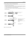
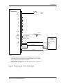
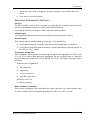
1
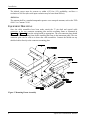
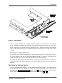
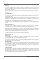
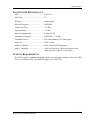
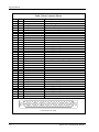
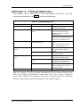
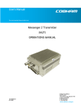
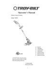
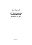
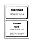
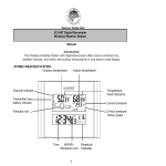
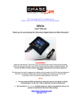
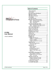
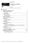
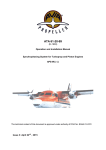
Apollo
Mode A/C Transponder
Model SL70
Installation Manual
October 1999
560-0402-00a
1999 by UPS Aviation Technologies. All rights reserved.
Printed in the U.S.A.
No part of this document may be transmitted, reproduced, or copied in any form or by any means
without the prior written consent of UPS Aviation Technologies. Due to our commitment to
constantly improve the quality and performance of our products, information contained in this
document is subject to change without notice.
UPS Aviation Technologies and Apollo are registered trademarks of UPS Aviation
Technologies.
UPS Aviation Technologies
P.O. Box 13549
Salem, OR 97309
Phone (503)581-8101
1-800-525-6726
In Canada 1-800-654-3415
FAX (503)364-2138
2345 Turner Rd. S.E.
Salem, OR 97302
U.S.A.
HISTORY OF REVISIONS
Revision
--00a
Date
8/26/99
10/4/99
Description
Initial release.
Added new connector pins and crimping tools, added radar
altimeter checkout and limitations
IMPORTANT NOTE
The conditions and tests required for TSO approval of this article are minimum performance
standards. It is the responsibility of those desiring to install this article on or within a specific
type or class of aircraft to determine that the aircraft operating conditions are within TSO
standards. The article may be installed only if further evaluation by the applicant documents
an acceptable installation and is approved by the Administrator.
ORDERING INFORMATION
To receive additional copies of this publication, order part # 560-0402, Apollo SL70 Mode
A/C Transponder Installation Manual.
REFERENCE PUBLICATIONS
Following are other publications referenced in this guide.
NOTES
Table of Contents
TABLE OF CONTENTS
SECTION 1 - INTRODUCTION................................................................................................. 1
ABOUT THIS MANUAL ...................................................................................................................... 1
APOLLO SL70 DESCRIPTION ............................................................................................................. 1
FEATURES ......................................................................................................................................... 2
REGULATORY COMPLIANCE ............................................................................................................. 2
UNPACKING THE EQUIPMENT............................................................................................................ 3
PACKAGE CONTENTS ........................................................................................................................ 3
OTHER REQUIRED MATERIALS ......................................................................................................... 3
SPECIAL TOOLS REQUIRED ............................................................................................................... 4
SECTION 2 - INSTALLATION .................................................................................................. 5
PRE-INSTALLATION INFORMATION.................................................................................................... 5
INSTALLATION OVERVIEW ................................................................................................................ 5
INSTALLATION CONSIDERATIONS...................................................................................................... 5
MOUNTING CONSIDERATIONS.................................................................................................................................... 5
MINIMUM SYSTEM CONFIGURATION ......................................................................................................................... 5
ALTITUDE INPUT........................................................................................................................................................ 5
ANTENNA .................................................................................................................................................................. 6
EQUIPMENT MOUNTING .................................................................................................................... 6
UNIT INSTALLATION / REMOVAL ............................................................................................................................... 7
ELECTRICAL CONNECTIONS .............................................................................................................. 7
POWER ...................................................................................................................................................................... 8
ALTITUDE INPUT........................................................................................................................................................ 8
SERIAL INTERFACE .................................................................................................................................................... 8
DISCRETE INPUTS ...................................................................................................................................................... 8
ANTENNA INSTALLATION AND CONNECTIONS .................................................................................. 9
POST INSTALLATION CHECKOUT..................................................................................................... 12
TEST MODE CHECKOUT AND SETUP ........................................................................................................................ 12
OPERATION / PERFORMANCE CHECKOUT ................................................................................................................ 13
INSTRUCTIONS FOR CONTINUED AIRWORTHINESS........................................................................... 15
SECTION 3 - SPECIFICATIONS............................................................................................. 17
ELECTRICAL ................................................................................................................................... 17
PHYSICAL ....................................................................................................................................... 17
ENVIRONMENTAL ........................................................................................................................... 18
ALTITUDE INPUT ............................................................................................................................. 18
DISCRETE INPUTS ........................................................................................................................... 18
SERIAL INTERFACE ......................................................................................................................... 18
TRANSPONDER PERFORMANCE ....................................................................................................... 19
ANTENNA REQUIREMENTS.............................................................................................................. 19
SECTION 4 - LIMITATIONS ................................................................................................... 21
INSTALLATION ................................................................................................................................ 21
OPERATIONAL ................................................................................................................................ 21
APPENDIX A - TROUBLESHOOTING.................................................................................. 23
CONTACTING THE FACTORY FOR ASSISTANCE ................................................................................ 24
Apollo SL70 Installation Manual
i
Table of Contents
APPENDIX B - PERIODIC MAINTENANCE ....................................................................... 25
BIENNIAL CHECK ........................................................................................................................... 25
CLEANING THE FRONT PANEL ........................................................................................................ 25
APPENDIX C - ENVIRONMENTAL QUALIFICATIONS .................................................. 27
APPENDIX E - SERIAL DATA PROTOCOL ........................................................................ 29
ALTITUDE INPUT / OUTPUT ......................................................................................................................................29
LIST OF TABLES
TABLE 1
TABLE 2
TABLE 3
TABLE 4
PACKAGE CONTENTS ........................................................................................................ 3
REAR CONNECTOR PINOUT ............................................................................................. 20
TROUBLESHOOTING GUIDE ............................................................................................. 23
ALTITUDE DATA FORMAT ............................................................................................... 29
LIST OF FIGURES
FIGURE 1
FIGURE 2
FIGURE 3
FIGURE 4
FIGURE 5
FIGURE 6
FIGURE 7
ii
SL70 FRONT PANEL ........................................................................................................ 2
MOUNTING FRAME ASSEMBLY ........................................................................................ 6
CABLE ROUTING .............................................................................................................. 7
COAX CABLE ASSEMBLY................................................................................................. 9
WIRING DIAGRAM - GRAY CODE ALTITUDE INPUT ....................................................... 10
WIRING DIAGRAM - SERIAL ALTITUDE INPUT................................................................ 11
UNIT DIMENSIONS ......................................................................................................... 17
Apollo SL70 Installation Manual
Introduction
SECTION 1 - INTRODUCTION
ABOUT THIS MANUAL
This manual describes the installation of the Apollo SL70 transponder . It is intended for use
by persons certified by the Federal Aviation Administration (FAA) to install aircraft avionics.
Section 1
Provides an introduction to the Apollo SL70 unit. TSO certification information
is also included in this section.
Section 2
Includes installation and checkout procedures.
Section 3
Includes complete specifications.
Section 4
Includes limitations for the equipment and installation.
Appendix A
Includes troubleshooting information.
Appendix B
Includes periodic maintenance requirements.
Appendix C
Includes the environmental qualification form.
Appendix E
Includes serial data protocol specifications.
APOLLO SL70 DESCRIPTION
The Apollo SL70 is a TSO-C74c, Class A2, mode A/C transponder. The SL70, in addition to
providing replies to ATC interrogations, includes an altitude display and altitude hold function
and user-friendly interface features including rotary knob squawk code selection, a VFR
button, and built-in self-test and diagnostics.
Apollo SL70 Installation Manual
1
Introduction
Figure 1 SL70 Front Panel
FEATURES
• small size 1.3” panel height
• full range input supply voltage
• high brightness LED display
• altitude display
• altitude hold function
• gray code or RS-232 serial data altitude input
• RS-232 altitude data output
• built-in self-test and diagnostics
REGULATORY COMPLIANCE
The Apollo SL70 is designed and tested to meet the following TSO:
•
FAA TSO-C74c, Class A2
The SL70 complies with the FCC requirements specified in:
•
CFR 47, Part 87, Aviation Services, Subpart D, Technical Requirements
The SL70 software is designed and tested to RTCA/DO-178B, level C.
Note: Un-authorized changes or modifications to the SL70 may void the
compliance to regulatory agency requirements and authorization for continued
equipment usage.
2
Apollo SL70 Installation Manual
Introduction
UNPACKING THE EQUIPMENT
Carefully unpack the equipment. Visually inspect the package contents for any evidence of
shipping damage. Retain all shipping containers and packaging material in case reshipment is
necessary.
PACKAGE CONTENTS
As shipped from the UPS Aviation Technologies factory, the Apollo SL70 package includes
most necessary items for installation other than supplies normally available at the installation
shop, such as wire and coax cable, the antenna, or any optional switches. The items included
in the package are listed in Table 1.
Table 1 Package Contents
Part #
Description
Apollo SL70 Installation Kit, Part # 424-0306-xx
162-0103 or
37 pin dsub connector shell
162-1577
162-0043
Right angle coax plug
202-0001
Cable tie
204-0037
Edge grommet
221-0400
4-40 x ¼ SS pan head Phillips machine screw with lock
washer
224-0404
4-40 x ¼ flat head Phillips machine screw
240-0008
9/16 OD flat washer
245-0022 or
Crimp contact for dsub, 20 to 24 awg wire
245-0027
265-0007
7/16” retaining ring
310-2295-00
Connector mounting bracket
310-5181-00
Mounting frame
998-0048
3/32 hex driver
Apollo SL70 Manual Kit, Part # 564-0072-xx
560-0401-00
SL70 User’s Manual
560-0402-00
SL70 Installation Manual
Qty
1
1
2
6”
10
2
1
37
1
1
1
1
1
1
OTHER REQUIRED MATERIALS
In addition to the materials supplied with the SL70, the following is required.
•
a suitable 2A circuit breaker
•
an altitude data source – either gray code or RS232
•
a standard transponder antenna (see Antenna information on pages 6 and 19)
Apollo SL70 Installation Manual
3
Introduction
SPECIAL TOOLS REQUIRED
Crimp Tool
A crimp tool meeting MIL specification M22520/1-01 and a positioner/locater are required to
ensure consistent, reliable crimp contact connections for the rear 15 pin connector. These tools
are available from:
For pin p/n 162-0100
Astro Tool Corp.
21615 SW TV Highway
Beaverton, OR 97006
Phone (503) 642-9853
Fax (503) 591-7766
Crimp tool:
Positioner:
Astro Tool part #615708
Astro Tool part #616356
For pin p/n 162-1575
4
ITT Cannon
1851 E. Deere Ave.
Santa Ana, CA 92705-6500
Phone (714) 261-5300
Fax
(714) 575-8324
Insertion tool:
Regular duty Crimp tool:
Regular duty Locator tool:
Heavy duty Crimp tool:
Heavy duty Locator tool:
ITT part # 274-7006-000 (Desc. CIET-20HD)
ITT part #995-0001-585 (Desc. M22520/1-01)
ITT part #995-0001-244 (Desc. TH25)
ITT part #995-0001-584 (Desc. M22520/2-01)
ITT part #995-0001-604 (Desc. M22520/2-08)
Apollo SL70 Installation Manual
Installation
SECTION 2 - INSTALLATION
This section describes the installation of the Apollo SL70 including mounting, wiring, and
connections. A post installation check-out procedure is included at the end of this section.
PRE-INSTALLATION INFORMATION
Always follow good avionics installation practices per FAA Advisory Circulars AC 43.13-1B,
43.13-2A, or current FAA guidance.
Follow the installation procedure in this section as it is presented for a successful installation.
Read the entire section before beginning the procedure. Perform the post installation checkout before closing the work area in case problems occur.
INSTALLATION OVERVIEW
A successful installation should start with careful planning including determination of
mounting location for the SL70, antenna location and mounting, connections to an altitude
data source, power, cable routing, and other required modifications.
Once the mounting location has been determined, prepare the mounting frame for installation.
It may be easier to complete the wiring harness and attach the connectors to the mounting
frame prior to installing the mounting frame in the aircraft.
INSTALLATION CONSIDERATIONS
MOUNTING CONSIDERATIONS
The SL70 is designed to mount in the avionics stack in the aircraft instrument panel within
easy view and reach of the pilot. The standard package includes the mounting frame for ease
of mounting, connections, and service of the unit. Allow an additional one inch clearance to
the rear of the mounting frame for connections and cables.
For typical installations, the SL70 does not require external cooling. When mounting the unit,
leave a clearance of 1/8 to 1/4 inch between avionics to allow for air circulation.
MINIMUM SYSTEM CONFIGURATION
The SL70 requires connections to the following equipment as a minimum:
•
power input
•
altitude data – gray code or RS232
•
a standard transponder antenna
ALTITUDE INPUT
The SL70 can use either a standard altitude gray code input from an encoding altimeter or an
RS-232 input from a serial encoder. For new installations, a serial encoder is recommended
because it simplifies the wiring and is more reliable. The SL70 can detect failures on the RS232 input, thereby eliminating erroneous mode C altitude replies.
Apollo SL70 Installation Manual
5
Installation
The altitude source must be accurate to within ±125 feet, 95% probability, and have a
resolution of 100 feet (the serial input resolution may be better than 100feet).
ANTENNA
The antenna shall be a standard transponder quarter wave monopole antenna, such as the TED
#104-12 or Comant CI-101.
EQUIPMENT MOUNTING
Once the cable assemblies have been made, attach the 37 pin dsub and coaxial cable
connectors to the rear connector mounting plate and the mounting frame as illustrated in
Figure 2 and Figure 3. Route the wiring bundle as appropriate. The rear connector plate should
be attached to the mounting frame before installing the frame in the instrument panel. The rear
connector plate can be used to tie down the cable assemblies. Connect the shields on any
shielded cables directly to the connector mounting plate.
Figure 2 Mounting Frame Assembly
6
Apollo SL70 Installation Manual
Installation
Figure 3 Cable Routing
Once the cable assemblies are complete and the connectors are attached to the mounting
frame, install the mounting frame assembly in the aircraft instrument panel. Be sure to use low
profile head screws so the unit will slide in and out freely. Attach the front of the mounting
frame to the instrument panel. Use support brackets to attach the rear of the frame to the
aircraft.
UNIT INSTALLATION / REMOVAL
To install the SL70 in the mounting frame, make sure the cam lock is rotated so the rear part
is up, then slide the unit into the frame and tighten with the 3/32 hex tool. The unit will be
pulled into the frame by the cam lock and the connectors will fully engage.
To remove the SL70 from the mounting frame, use the hex tool and turn the tool CCW. The
unit will be pushed out of the frame by the cam lock assembly. No special extraction tools are
required.
ELECTRICAL CONNECTIONS
The SL70 installation kit includes a 37 pin dsub shell and crimp contacts. The crimp contacts
are specified for 20 to 24 AWG wire. Make the crimp connections with a crimp tool as
specified in the Special Tools Required section on page 4. All wires should be 20 to 24 AWG
unless otherwise specified. Wiring diagrams are included on pages 10 and 11.
Apollo SL70 Installation Manual
7
Installation
POWER
The SL70 is internally fused at 3 amps. A separate 2 amp circuit breaker or fuse should be
installed for downline overload or short circuit protection. Make the power connections to the
SL70 using 20 AWG wire.
Note: Circuits should be protected in accordance with guidelines in AC 43.13-1B, chapter 11,
section 4.
ALTITUDE INPUT
The SL70 can use altitude data from either a standard gray code altitude or from an RS-232
serial altitude source.
If using the gray code altitude input, connections can be made directly from the SL70 to the
altitude source. Isolation diodes are included within the SL70. Make sure a common ground
connection exists, or connect a ground wire between the source and the SL70.
If using the RS-232 serial altitude input, make the connections as described in the following
section.
SERIAL INTERFACE
The SL70 includes an RS-232 serial port which can be used for inputting or outputting
altitude data. This is an optional connection if the altitude gray code input is used.
When making serial connections to the SL70, use a shielded two or three conductor cable.
Make the RxD, TxD, and serial ground connections on the 37 pin dsub connector. Connect the
shield to the rear of the mounting frame on the connector plate.
Complete serial interface specifications are included in Appendix E.
DISCRETE INPUTS
Remote Ident
The ident input can be connected to a remotely mounted momentary switch to initiate the
ident function the same as using the front panel IDENT button.
When using the ident input, connect it to a remotely mounted momentary switch, and connect
the other terminal of the switch to ground.
Remote Standby
The standby input is for use when the installation includes more than one transponder. When
two transponders are installed, connect the standby input to a two position selector switch,
with the common on the switch connected to ground. The SL70 will be in standby when the
input is pulled low to ground.
Suppresion Input
The suppress input is used when installed with a DME that includes a suppression output. The
transponder will be suppressed, or will not generate replies, when the input is driven high
from the DME (or other source). To use the suppression input, connect it to the suppression
output on a DME (or other appropriate suppression source).
8
Apollo SL70 Installation Manual
Installation
ANTENNA INSTALLATION AND CONNECTIONS
The antenna should be mounted in a vertical position in an area on the bottom of the aircraft
away from other antennas or landing gear.
The antenna coax cable should be a double shielded low loss cable and must have a cable loss
of < 3 dB at 1090MHz, including connectors. A typical installation should have a cable loss of
1½ to 2 dB. Several suitable coaxes are RG142B and RG400.
The assembly of the rear panel coax connector included with the installation kit is illustrated
in the following figure.
Shield 0.250
Cable
1.000
0.125
STEP 1
Insulation
-Slide shrink tube over cable.
-Strip cable as shown.
Shrink
Tube
.125
STEP 2
-Flare Outer Shield as Shown
Cap
Solder Outer Shield
to Connector
STEP 3
Matching Ring
Solder Center
Conductor
-Place cable in connector as shown placing inner
shield inside connector.
-Flatten outer shield against connector.
-Solder outer shield to connector.
-Solder center conductor
-Slide matching ring into connector and around
conductor.
-Attach cap.
Solder Cap
2 Places
STEP 4
-Solder cap into place, 2 Places.
-Shrink tube as shown.
Figure 4 Coax Cable Assembly
Apollo SL70 Installation Manual
9
Installation
SL70
Transponder
2A Breaker
Power
1
+
Ground
2
-
C4
15
C2
34
Avionics
Power
Altitude
Encoder or
C2 Digitizer
C4
C1
C1
16
B4
32
B4
B2
14
B2
B1
33
B1
A4
12
A4
A2
31
A2
A1
13
A1
D4
35
D4
Ground
30
Ground
Ident
10
Standby
29
Note 2 (Optional)
Suppress
19
Note 3 (Optional)
Ground
37
Suppress return
TxD
5
RxD
4
Ground
3
Remote
Ident
(Optional)
GPS Unit
RS-232 Serial Altitude
Output (Optional)
RxD
Ground
Shielded Cable
Chassis Ground
Chassis Ground
Coax Cable
To Antenna
Notes:
1. Select the gray code input in the setup mode when using the parallel gray code
altitude input.
2. Use standby input to select between two transponders using a selector switch.
Unit is in standby when input switched to ground.
3. Suppression input, typically connected to DME suppression output. Transponder is
suppressed when input is high.
Figure 5 Wiring Diagram - Gray Code Altitude Input
10
Apollo SL70 Installation Manual
Installation
SL70
Transponder
2A Breaker
Power
1
+
Ground
2
-
C4
15
C2
34
C1
16
B4
32
B2
14
B1
33
A4
12
A2
31
A1
13
D4
35
Ground
30
Ident
10
Standby
29
19
Note 3 (Optional)
Ground
37
Suppress return
TxD
5
RxD
4
Ground
3
Remote
Ident
(Optional)
Note 2 (Optional)
Suppress
Avionics
Power
Altitude
Encoder or
Serializer
RS-232 Serial Altitude Input
TxD
Ground
Shielded Cable
Chassis Ground
Chassis Ground
Coax Cable
To Antenna
Notes:
1. Select altitude input in the setup mode when using RS-232 serial altitude input.
2. Use standby input to select between two transponders using a selector switch.
Unit is in standby when input switched to ground.
3. Suppression input, typically connected to DME suppression output. Transponder is
suppressed when input is high.
Figure 6 Wiring Diagram - Serial Altitude Input
Apollo SL70 Installation Manual
11
Installation
POST INSTALLATION CHECKOUT
Once the unit is installed, complete the checkout procedure to verify proper operation. Refer
to the user’s guide for operating instructions.
The steps that are not applicable to a particular installation may be skipped. Fill out the
checkout log sheet during the checkout procedure. The log sheet of page 14 may be
photocopied if desired.
Mounting / Wiring Check
Verify that all cables are properly secured and shields are connected to the rear of the
mounting frame. Check that cables do not interfere with the movement of the aircraft controls.
TEST MODE CHECKOUT AND SETUP
The SL70 has a built-in setup mode to simplify the checkout. To operate the SL70 in the setup
mode, hold down the “IDENT” and “ALT” buttons while switching on the power. To return to
normal operation, switch the power off, then back on.
Altitude Input Source Selection
The SL70 altitude input type must be selected. To select the altitude input type:
1. In test mode, rotate the LARGE knob to the “SL70 CONF” (SL70 Configuration) page,
then rotate the SMALL knob to the “ASRC” (Altitude source) page.
2. Press IDENT (the altitude type field will start to flash), rotate the SMALL knob to select
the altitude type, then press IDENT to save the selection.
The altitude types that can be selected are:
GRAY ..................................... to use the parallel gray code input
SER ........................................ to use the RS-232 serial altitude input
RS-232 Baud Rate Selection
If using the RS-232 serial interface, the baud rate must be selected to match the connected
equipment. To select the baud rate:
1. In test mode, rotate the LARGE knob to the “SL70 CONF” (SL70 Configuration) page,
then rotate the SMALL knob to the “BAUD” (baud rate) page.
2. Press IDENT (the baud rate field will start to flash), rotate the SMALL knob to select the
desired baud rate, then press IDENT to save the selection.
The baud rates available are 1200, 2400, 4800, 9600, and 19200.
VFR Code Selection
The VFR code used by the SL70 when pressing the “VFR” button can be selected as
appropriate for the aircraft’s operating area. To change the VFR code:
1. In test mode, rotate the LARGE knob to the “SL70 CONF” (SL70 Configuration) page,
then rotate the SMALL knob to the “VFR” (VFR code selection) page.
2. Press IDENT (the first VFR code character will start to flash).
12
Apollo SL70 Installation Manual
Installation
3.
Rotate the SMALL knob to change the character, rotate the LARGE knob to move the
cursor.
4. Press IDENT to save the selection.
OPERATION / PERFORMANCE CHECKOUT
Self Test
The SL70 includes a self test that is executed every time the unit is turned on that checks the
receiver and transmitter operation as well as other internal functions.
Verify that the unit does not display a failure indication when turned on.
Altitude Input
Verify that the displayed altitude matches the altimeter pressure altitude (at 29.92).
External Inputs
If the external ident or standby inputs are connected, verify operation by:
a) Verify that the unit goes to standby when the external standby input is pulled low.
b) Verify that the ident LED turns on when the external ident button is pressed (must be in
the “ON” or “ALT” modes).
Performance (Ramp) Test
After installation, the transponder should be tested as specified in Appendix F of CFR 14 part
43, to AC 43-6A, and/or other appropriate regulations. The test is typically done as a ramp test
using a transponder ramp test set, such as the IFR ATC-600A. The ramp test includes checks
as follows.
Reference part 43 Appendix F:
a)
reply frequency
b) suppression
c)
receiver sensitivity
d) reply RF output power
Reference AC 43-6A:
• altitude reporting
Radar Altimeter (if installed)
If the aircraft is equipped with a radar altimeter, proper operation of the radar altimeter must
be verified with the SL70 Transponder operating in the ON (A) or ALT (C) mode.
Apollo SL70 Installation Manual
13
Installation
APOLLO SL70 POST-INSTALLATION CHECKOUT LOG
Date: ___/___/___
By: _______________
CONFIGURATION INFORMATION:
Apollo SL70 430-6090-____ Mod ___
Serial #_______________
TEST MODE CHECKOUT AND SETUP:
Self Test:
[ ] Pass
[ ] Fail
Altitude source:
[ ] Gray code (GRAY)
[ ] Serial RS-232 (SER)
OPERATION / PERFORMANCE CHECK:
Altitude data (on display):
[ ] Pass
External inputs:
[ ] Remote ident checked [ ] N/A
[ ] External standby
[ ] N/A
RS-232 baud rate: _________
VFR Code: ________
Performance verification:
[ ] Pass
Radar Altimeter (if installed):
[ ] No interference
COMMENTS:
14
Apollo SL70 Installation Manual
Installation
INSTRUCTIONS FOR CONTINUED AIRWORTHINESS
Modification of an aircraft for the installation of the SL70 obligates the aircraft operator to
include the maintenance information provided by this section in the operator’s Aircraft
Maintenance Manual and the operator’s Aircraft Scheduled Maintenance Program.
1. Maintenance Manual information (system description, operation, location, removal,
testing, etc) is contained within this document and any information should be copied to,
and /or included with, the operator’s airplane Maintenance Manual.
2. Line Replaceable Unit (LRU) part numbers and other necessary part numbers contained in
the installation data package should be placed into the aircraft operator’s airplane
Illustrated Parts Catalog (IPC).
3. The specific wiring diagram information, along with the supplemental information
described in the Installation Manual, pertaining to the installation of this unit, should be
placed into the aircraft operator’s airplane Wiring Diagram Manuals.
4. Scheduled Maintenance Program task to be added to the operator’s maintenance program
are found in Appendix B - Periodic Maintenance, of this installation manual.
Apollo SL70 Installation Manual
15
Installation
NOTES
16
Apollo SL70 Installation Manual
Specifications
SECTION 3 - SPECIFICATIONS
This section includes detailed electrical, physical, environmental, and performance
specifications for the Apollo SL70.
ELECTRICAL
Input voltage ............................................. 10VDC to 35VDC, reverse polarity protected
Input current.............................................. 500mA typical, 1.4A max at 14VDC
270mA typical, 660mA max at 28VDC
Input power............................................... 7 watts typical (8 pulse reply, 200 replies / second)
20 watts max (12 pulse reply, 1200 replies / second)
5.8 watts standby
Internal fuse .............................................. 3 amp slow blow (UPS Aviation Technologies
#S172-0007-012)
Memory backup ........................................ Internal EEPROM
PHYSICAL
Height ....................................................... 1.30 inches (3.30 cm)
Width ........................................................ 6.25 inches (15.88 cm)
Depth ........................................................ 11.452 inches (29.09cm) behind panel, including
mounting frame and connectors
Weight (with mounting frame) ................. 2.64 lb. (1.2 kg)
Required clearance.................................... Allow one inch behind unit for connector and cable
clearance
0.648
11.452
10.420
1.038
Mounting Holes (8x)
0.219
0.862
0.375
3.625
3.025
1.750
1.300
1.625
6.250
1.300
Figure 7 Unit Dimensions
Apollo SL70 Installation Manual
17
Specifications
ENVIRONMENTAL
The Apollo SL70 is designed and tested to meet appropriate categories of RTCA/DO-160D.
The Environmental Qualification Form is included in Appendix C.
Operating temperature.............................. -20°C to +55°C
Storage temperature.................................. -55°C to +85°C
Temperature variation .............................. 2°C per minute
Humidity................................................... 95% at 50°C for 6 hours (2 day cycle)
Maximum altitude .................................... 25,000 feet
Cooling ..................................................... Not required
ALTITUDE INPUT
10 bit gray code ........................................ Uses 10 bit gray code altitude data, includes
isolation diodes.
Range: -1000feet to 63,000 feet
On: <= 3.5 volts, Off: open
Serial input ............................................... Uses RS-232 serial data input (See Appendix E –
Serial Interface Specifications)
Note: The altitude data input type must be selected using the setup function during the post
installation checkout.
DISCRETE INPUTS
Remote Ident ............................................ Input pulled low momentarily to initiate ident
transmission (same function as front panel button)
On: <= 3.5 volts, Off: open
Standby input............................................ Input pulled low to disable the transponder (will not
generate replies)
On: <= 3.5 volts, Off: open
Suppression input ..................................... Input pulled high to initiate suppression – typically
connected to DME suppression output
Suppressed: >= 5.0 volts;
Not suppressed: < 2.5 volts (or open)
SERIAL INTERFACE
RS-232...................................................... Defined in Appendix E – Serial Interface
Specifications
18
Apollo SL70 Installation Manual
Specifications
TRANSPONDER PERFORMANCE
TSO........................................................... TSO-C74c
TSO Class ................................................. 2A
Warm-up................................................... none required
Receiver Frequency .................................. 1030 MHz
Sensitivity (MTL) ..................................... –72 dBm
Dynamic Range......................................... > 50 dB
Side Lobe Suppression ............................. 2 pulse (P1,P2)
Transmitter Frequency.............................. 1090 MHz +/- 120 kHz
Transmitter Power .................................... 250 watts minimum, 325 watts typical
Reply rate.................................................. 1200 / second
Mode A Capability ................................... 4096 codes plus SPI ident pulse
Mode C Capability.................................... -1000 to 63,000 feet, 100 foot increments, from
either gray code or RS-232 serial inputs
ANTENNA REQUIREMENTS
The SL70 requires a standard transponder quarter wave monopole antenna, such as the TED
#104-12 or Comant CI-101, and should be approved to TSO-C74c.
Apollo SL70 Installation Manual
19
Specifications
Table 2 Rear Connector Pinout
Pin #
I/O
Connection
Function
1
2
3
4
5
6
7
8
9
10
11
12
13
14
15
16
17
18
19
20
21
22
23
24
25
26
27
28
29
30
31
32
33
34
35
36
37
I
I
O
I
O
O
O
I
I
I
-I
I
I
I
I
--I
O
I
O
--I
I
--I
-I
I
I
I
I
---
Power +
Power ground
Serial ground
RxD
TxD
Reserved
Reserved
Reserved
Reserved
Ident
NC
A4
A1
B2
C4
C1
Reserved
Reserved
Suppress
NC
Reserved
Reserved
NC
Ground
Reserved
Reserved
Ground
Ground
Standby
Ground
A2
B4
B1
C2
D4
Reserved
Ground
main DC power input
main DC power ground
RS-232 serial ground
RS-232 serial data input
RS-232 serial data output
remote ident input (ground momentarily for ident)
no connection
A4 altitude gray code input
A1 altitude gray code input
B2 altitude gray code input
C4 altitude gray code input
C1 altitude gray code input
remote suppression input (high for suppression)
no connection
no connection
remote standby input (ground for standby)
A2 altitude gray code input
B4 altitude gray code input
B1 altitude gray code input
C2 altitude gray code input
D4 altitude gray code input
1
19
20
37
Viewed from rear of unit
20
Apollo SL70 Installation Manual
Limitations
SECTION 4 - LIMITATIONS
INSTALLATION
Aircraft installation must be made in accordance with this installation manual and applicable
FAA regulations and advisory circulars.
Harmonic Interference
Transponders reply to interrogation on a frequency of 1090 MHz. The 4th harmonic (4.36
GHz) may be in the range of some radar altimeter devices. If the SL70 is installed in an
aircraft with a radar altimeter, proper operation of the radar altimeter must be verified with the
SL70 Transponder operating in the ON (A) or the ALT (C) mode.
OPERATIONAL
The SL70 must be operated within the limitations as follows, or by other regulatory guidance
as appropriate.
1. The altitude reply data may be verified by comparing the pressure altitude display to the
aircraft altimeter relative to a barometric setting of 29.92.
2. The transponder is to be operated in compliance with CFR 14 section 91.215 for ATC
transponder and altitude reporting equipment.
3. The transponder must be tested as specified in CFR 14 section 91.413 within the previous
24 months.
Apollo SL70 Installation Manual
21
Limitations
NOTES
22
Apollo SL70 Installation Manual
Troubleshooting
APPENDIX A - TROUBLESHOOTING
This appendix provides information to assist troubleshooting if problems occur after
completing the installation. Use Table 3 to assist in troubleshooting.
Table 3 Troubleshooting Guide
Problem
Cause
The SL70 does not power on.
The unit is not getting power.
The altitude is not correct.
The altitude display is “---“
The unit fails the start-up
self-test.
The unit does not generate
replies.
Solution
Check power connections, breakers,
and main avionics switch.
The unit is not getting the correct
If the gray code inputs are used,
altitude.
check all connections from the
altitude source and/or verify the
altitude source.
If the serial altitude input is used,
check for the correct baud rate and
connections to the altitude source.
The unit is not getting an altitude, or Check the connections to the altitude
the altitude is invalid.
source.
Check the altitude source to make
sure it is operating correctly.
TX fails.
Check antenna connections. May
have an open, a short, or a bad
VSWR.
Other failure.
The unit may need repair. Contact the
factory for assistance.
The unit is in standby.
The unit must be in either the “On” or
“Alt” modes to generate replies.
The unit is not receiving interrogation Check the antenna connections. If the
signals.
unit does not “Fail” the receive test,
then check antenna connections.
No interrogation signal available.
Need to either use a ramp test set or
climb to altitude where ATC radar
service is available.
If the SL70 displays a “Test Fail” message when turned on, the test status and source of the
failure can be displayed by rotating the SMALL knob. If the source is either a transmit or
receive failure, the unit will not operate. If the source is any other item, the unit should
continue to operate (press any of the mode buttons), but should be repaired.
Apollo SL70 Installation Manual
23
Troubleshooting
CONTACTING THE FACTORY FOR ASSISTANCE
If the Apollo SL70 unit fails to operate despite troubleshooting efforts, contact the UPS
Aviation Technologies factory for assistance.
UPS Aviation Technologies
2345 Turner Rd. S.E.
Salem, Oregon 97302
U.S.A.
Phone (503)581-8101 or 1-800-525-6726
Be prepared to offer the following information about the installation:
24
•
Installation configuration (accessories, antenna, ...)
•
Model number, part number with mod levels, and serial number
•
Software versions (The software versions can be displayed in the setup mode by
rotating the LARGE knob to the “SW VER” page, and rotating the SMALL knob to
display the microcontroller and FPGA versions.)
•
Description of problem
•
Efforts made to isolate the problem
Apollo SL70 Installation Manual
Periodic Maintenance
APPENDIX B - PERIODIC MAINTENANCE
The Apollo SL70 is designed to not require any regular general maintenance except as
included in this section.
BIENNIAL CHECK
The transponder must be tested within the previous 24 months as specified in 91.413 of the
FAA regulations.
No other periodic maintenance is required.
CLEANING THE FRONT PANEL
The front bezel, keypad, and display can be cleaned with a soft cotton cloth dampened with
clean water. DO NOT use any chemical cleaning agents. Extreme care must be taken to avoid
scratching the surface of the display.
Apollo SL70 Installation Manual
25
Periodic Maintenance
NOTES
26
Apollo SL70 Installation Manual
Environmental Qualifications
APPENDIX C - ENVIRONMENTAL QUALIFICATIONS
The Apollo SL70 has been tested to the following environmental categories per procedures
defined in RTCA/DO-160D.
Environmental Qualification Form
Manufacturer:
UPS Aviation Technologies
2345 Turner Road S.E.
Salem, Oregon 97302
Nomenclature: Apollo SL70
Part No.: 430-6090-xxx
TSO No.: TSO_C74c
Conditions
Temperature and Altitude
In-flight Loss of Cooling
Altitude
Decompression
Overpressure
Temperature Variation
Humidity
Section Description of Conducted Tests
Vibration
8.0
Explosion Proofness
Waterproofness
Fluids Susceptibility
Sand and Dust
Fungus Resistance
Salt Spray
Magnetic Effect
Power Input
9.0
10.0
11.0
12.0
13.0
14.0
15.0
16.0
Voltage Spike
Audio Frequency Conducted
Susceptibility – Power Inputs
Induced Signal Susceptibility
Radio Frequency Susceptibility
(Radiated and Conducted)
Emission of Radio Frequency
Energy
Lightning Induced Transient
Susceptibility
Lightning Direct Effects
Icing
Electrostatic Discharge (ESD)
Remarks:
17.0
18.0
Equipment tested to Category B1 with .......
No cooling required
Equipment tested to 25,000 feet
Equipment tested for decompression to 25,000 feet
Equipment tested for overpressure
Equipment tested to Category C, 2°C/min
Equipment tested to Category A, standard humidity
environment
Equipment tested for both operational and crash safety
shocks. (Equipment operates normally after both the crash
safety shocks.)
Equipment tested without shock mounts to Categories
S(B,M)
Equipment identified as Category X, no test required
Equipment identified as Category X, no test required
Equipment identified as Category X, no test required
Equipment identified as Category X, no test required
Equipment identified as Category X, no test required
Equipment identified as Category X, no test required
Equipment is Class Z
Equipment tested to Categories A (28volt systems) & B (14
and 28 volt systems)
Equipment tested to Category A
Equipment tested to Categories A & B
19.0
20
Equipment tested to Category Z
Equipment tested to Category V
21
Equipment tested to Category M
22.0
Equipment tested to A3 and B2
23.0
24.0
25.0
Equipment identified as Category X, no test required
Equipment identified as Category X, no test required
Equipment tested to Category A
Operational Shocks and Crash
Safety
Apollo SL70 Installation Manual
4.0
4.5.4
4.6.1
4.6.2
4.6.3
5.0
6.0
7
27
Environmental Qualifications
NOTES
28
Apollo SL70 Installation Manual
Serial Data Protocol
APPENDIX E - SERIAL DATA PROTOCOL
This appendix includes the RS-232 serial port interface specifications.
ALTITUDE INPUT / OUTPUT
The SL70 will output altitude data whenever it is available, either from the gray code or serial
input.
The SL70 will accept altitude input data when the serial altitude data source is selected.
The format for the altitude input and output data is as follows.
Baud rate................................ 1200 to 19200 (default = 1200)
Data bits................................. 8
Stop bits................................. 1
Parity...................................... none
Message length ...................... 17 characters
Expected input rate ................ once per second
Output rate ............................. once per second
Table 4 Altitude Data Format
Byte
1
2
3
4
5
6-10
11
12
13-14
15-16
17
Data Format
“#”
“A”
“L”
““
“+” or “-“
ddddd
“T”
“+” or “-“
dd
dd
<CR>
Description
ASCII “#” (023h)
ASCII “A” (041h)
ASCII “L” (04Ch)
ASCII space (020h)
Altitude sign: ASCII “+” or “-“ (02Bh or 02Dh)
Altitude in feet, right justified, with leading zeros
ASCII “T” (054h)
Temperature sign: ASCII “+” or “-“ (02Bh or 02Dh)
Altimeter temperature
Checksum of bytes 1 through 14, computed in hex, output is
ASCII format (i.e., “FA” hex)
ASCII carriage return (0Dh)
The SL70 will interpret several altitude input codes as status or error codes, in the place of the
altitude data, as follows.
“-09980” ................................ Encoder heater not ready, expected during encoder warmup or if there is a loss of signal from the encoder. The SL70
will reply with only framing pulses to mode C
interrogations.
Apollo SL70 Installation Manual
29
Serial Data Protocol
“-09981”................................ Possible hardware problem, expected from the encoder
indicating a temperature above normal. The SL70 will reply
with only framing pulses to mode C interrogations.
“-09982”................................ Altitude out of range, expected from the encoder indicating
that the altitude is out of a valid range. The SL70 will reply
with only framing pulses to mode C interrogations.
When the gray code input is selected, the SL70 will output “-09981” if an invalid code is
detected or “-09982” if the altitude is out of range.
30
Apollo SL70 Installation Manual
Serial Data Protocol
NOTES
Apollo SL70 Installation Manual
31