1
282
282
Service.
AUDI A8 ´03 - Technical Features
Self Study Programme 282
All rights reserved. Subject to
technical modification.
Copyright* 2002 AUDI AG, Ingolstadt
Department I/VK-35
D-85045 Ingolstadt
Fax 0841/89-36367
000.2811.02.20
Technical status as at 09/02
Printed in Germany
For internal use only
Complete vehicle information
The design and operation of the Audi A8 ´03 are described in the following Self Study
Programmes:
SSP 283 – 6-speed automatic gearbox 09E in the Audi A8 '03 - Part 1
SSP 284 – 6-speed automatic gearbox 09E in the Audi A8 '03 - Part 2
SSP 285 – Running gear in the Audi A8 '03
SSP 286 – New data bus systems - LIN, MOST, BluetoothTM
SSP 287 – Audi A8 '03 - Electrical components
SSP 288 – Audi A8 '03 - Distributed functions
SSP 289 – Adaptive cruise control in the Audi A8 '03
SSP 292 – Adaptive air suspension in the Audi A8 '03
SSP 293 – Audi A8 '03 - Infotainment
Other helpful information on the
Audi A8 ´03 can be found on the adjacent
CD ROMs.
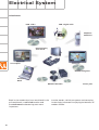
Electrical system
CAN data bus 2
Contents
Page
Introduction . . . . . . . . . . . . . . . . . . . . . . . . . . . . . . . . . . . . . . . . . . 4
Body . . . . . . . . . . . . . . . . . . . . . . . . . . . . . . . . . . . . . . . . . . . . . . . . 6
Passenger Protection
System layout . . . . . . . . . . . . . . . . . . . . . . . . . . . . . . . . . . . . . . . . . . . . . . . . 14
Block diagram . . . . . . . . . . . . . . . . . . . . . . . . . . . . . . . . . . . . . . . . . . . . . . . . 16
Safety systems . . . . . . . . . . . . . . . . . . . . . . . . . . . . . . . . . . . . . . . . . . . . . . . 18
Engine, Mechanics
Technical data of V8 4.2 l 5V engine . . . . . . . . . . . . . . . . . . . . . . . . . . . . . .
Technical data of V8 3.7 l 5V engine . . . . . . . . . . . . . . . . . . . . . . . . . . . . . .
System layout . . . . . . . . . . . . . . . . . . . . . . . . . . . . . . . . . . . . . . . . . . . . . . . .
Electrohydraulic torque reaction support . . . . . . . . . . . . . . . . . . . . . . . . .
Exhaust system . . . . . . . . . . . . . . . . . . . . . . . . . . . . . . . . . . . . . . . . . . . . . . .
Fuel tank . . . . . . . . . . . . . . . . . . . . . . . . . . . . . . . . . . . . . . . . . . . . . . . . . . . .
Automatically controlled starting . . . . . . . . . . . . . . . . . . . . . . . . . . . . . . . .
24
25
30
32
33
34
41
Gearbox . . . . . . . . . . . . . . . . . . . . . . . . . . . . . . . . . . . . . . . . . . . . 45
Running Gear
Front axle . . . . . . . . . . . . . . . . . . . . . . . . . . . . . . . . . . . . . . . . . . . . . . . . . . .
Rear axle . . . . . . . . . . . . . . . . . . . . . . . . . . . . . . . . . . . . . . . . . . . . . . . . . . . .
4-level air suspension . . . . . . . . . . . . . . . . . . . . . . . . . . . . . . . . . . . . . . . . .
System layout . . . . . . . . . . . . . . . . . . . . . . . . . . . . . . . . . . . . . . . . . . . . . . . .
Electric parking brake . . . . . . . . . . . . . . . . . . . . . . . . . . . . . . . . . . . . . . . . .
Adaptive cruise control . . . . . . . . . . . . . . . . . . . . . . . . . . . . . . . . . . . . . . . .
49
50
51
52
53
54
Electrical System
Bus topology . . . . . . . . . . . . . . . . . . . . . . . . . . . . . . . . . . . . . . . . . . . . . . . . . 58
Convenience and security electronics . . . . . . . . . . . . . . . . . . . . . . . . . . . . 64
Lighting system . . . . . . . . . . . . . . . . . . . . . . . . . . . . . . . . . . . . . . . . . . . . . . 68
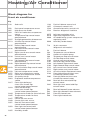
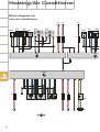
Heating/Air Conditioner
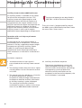
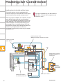
Design and operation. . . . . . . . . . . . . . . . . . . . . . . . . . . . . . . . . . . . . . . . . .
Operating principle . . . . . . . . . . . . . . . . . . . . . . . . . . . . . . . . . . . . . . . . . . .
Blower unit/air routing . . . . . . . . . . . . . . . . . . . . . . . . . . . . . . . . . . . . . . . . .
System layout . . . . . . . . . . . . . . . . . . . . . . . . . . . . . . . . . . . . . . . . . . . . . . . .
Block diagram for front air conditioner . . . . . . . . . . . . . . . . . . . . . . . . . . .
Block diagram for rear air conditioner . . . . . . . . . . . . . . . . . . . . . . . . . . . .
The Self Study Programme contains information on design
features and functions.
New
72
74
76
80
86
88
Attention
Note
The Self Study Programme is not intended as a Workshop
Manual. Values given are only intended to help explain the
subject matter and relate to the software version applicable at
the time of SSP compilation.
Use should always be made of the latest technical publications
when performing maintenance and repair work.
3
Introduction
Introduction
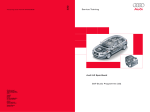
The new Audi A8 is designed to replace its
predecessor of the same name which achieved
a total production figure of 105,092 since its
introduction in June 1994. This was the first
standard saloon with aluminium body and
epitomised a new philosophy in the luxury
vehicle sector.
This body concept was further perfected in
the Audi A2 and the design of the Audi A8 ´03
reflects the experience gained from both
projects.
The aim when developing the Audi A8 ´03 was
not merely to surpass its predecessor in
terms of technical features and details.
The weight-saving Audi Space Frame ASF
represented a major breakthrough in terms of
enhanced vehicle dynamics, whilst at the same
time solving the problem of increasing weight.
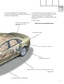
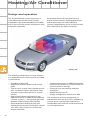
Active head restraints
for front seats
Convenience/infotainment control
via multimedia interface (MMI)
3.7 or 4.2 l V8 engine
with intake manifold
changeover function
Adaptive cruise control (ACC)
with radar sensor
in front bumper
4
Headlight with adaptive
light function
As the Audi flagship, the new Audi A8 is
intended to symbolise the product identity of
the next Audi generation.
An uncompromising sporty character, clearcut design, innovative technological systems
and the highest possible quality level
combine to provide an unforgettable driving
experience.
In other words:
Automatic boot lid opening
and closing function
(optional)
Audi at its proverbial best.
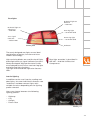
LED-type tail lights
4-level air suspension
Electric parking brake
"Advanced Key" entry and start authorisation system
SSP282_025
6-speed automatic gearbox 09E
5
Body
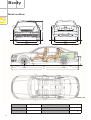
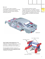
1444
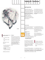
Brief outline
976
1615
1894
2028
125
714
1629
971
2944
1136
5051
SSP282_026
Kerb weight
6
1,780 kg
Turning circle
12 m
Tank capacity
approx. 90 litres
Gross weight
Luggage compartment volume
Drag coefficient
2,380 kg
approx. 500 l
0.27 Cd
Body
The Audi A8 ´03 sets new standards in its
class by combining lightweight construction
with outstanding stability. This is achieved
through the use of innovative Audi Space
Frame technology for the body design of the
Audi A8.
The technical progress reflected by the
unique body concept stems from the
consistent implementation of experience
gained from the aluminium Audi A8 and A2
models.
Based on the findings obtained from these
vehicles, it was possible to further reduce the
number of body components and
significantly increase the level of automation
in the production process as compared to the
Audi A8 predecessor model.
SSP282_027
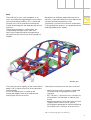
The static torsional rigidity of the new Audi A8
body is 60 % higher than that of the previous
Audi A8 body.
A crucial contribution is made to the
increased rigidity level by the advanced
Audi Space Frame structure.
Characteristic features of the new structure:
– Large castings with numerous integrated
functions and a high degree of joint
strength
– IHF* sections – optimum cross sections at
all locations, for example at side of roof
frame
– Sheet metal panels with high levels of local
rigidity thanks to the use of special
technologies designed to achieve differing
functional cross sections and structures
*IHF = Internal high-pressure forming
7
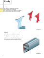
Body
A-pillar
The A-pillar is made of two cast shells
connected by rivets and welds.
The shells enclose the sill panel at the bottom
and the continuous roof frame at the top.
SSP282_029
Sill panel
Use is made for the sill panel of a 3-piece
extruded section.
The extruded section must be replaced in the
event of sill panel damage.
Depending on the nature of the damage,
either the entire section has to be replaced or
parts of it by way of three separating sleeves.
SSP282_030
8
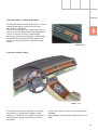
Rear end
The rear end has been completely
redeveloped. The two large central castings
are the one connecting the sill panel/
longitudinal member and the C/D-pillar
connecting element.
The sill panel/longitudinal member
connecting element is the largest casting. It
supports the entire rear sub-frame and links
the rear longitudinal member to the sill panel.
Its great rigidity is designed to protect the
tank in between in the event of a rear-end
collision.
SSP282_032
Large upper castings
Extruded sections
The C/D-pillar connecting element (large
upper casting) accommodates the
suspension strut at the top and the seat belt
at the front, in addition to forming the
terminating side section of the roof frame.
The large upper and lower castings are
interlinked by way of two straight extruded
sections and form the framework for the air
suspension strut holder.
Large lower castings
SSP282_033
9
Body
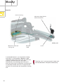
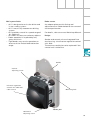
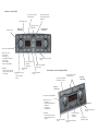
Boot lid
Foam encasing
Electronic boot lid lock
with microswitch
SSP282_035
Motor for automatic
closing aid
Bowden
cable
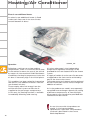
A standard feature is an automatic closing
aid, which is actuated by a Bowden cable
separately from the catch. After the latch has
closed, a mechanism pulls the catch
downwards, overcoming the build-up of
pressure occurring. On locking, a microswitch
in the boot lid lock transmits a signal to the
control unit to activate the automatic closing
aid.
10
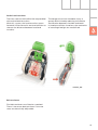
Catch
The drive unit is only encased in foam and
inserted between side panel and battery.
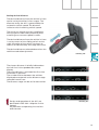
Automatic boot lid
Hinge mechanism
(open)
Boot lid
control unit J605
Button in driver's door
Button on boot lid
Vehicle key
SSP282_036
Pressing the button in the driver's door or on
the boot lid, or remote control actuation,
effects release and motor-driven opening of
the boot lid. Automatic boot lid closing can
only be implemented by way of the boot lid
button.
In the event of manual boot lid actuation, the
electric motor is disconnected by way of a
magnetic coupling, thus permitting the boot
lid to be moved by hand. On closing the boot
lid, the drive is deactivated via a microswitch
at the latch and the automatic closing aid
activated.
An electric motor flanged directly to the
swivel joint of the right boot lid hinge opens
or closes the boot lid.
As a general rule, interruption of automatic
actuation always causes the boot lid to be
disconnected from the drive unit and thus
set to manual mode.
11
Body
Front doors
The doors are made up of a combination of
aluminium panels, aluminium sections and
aluminium castings.
Optimised rib geometry and wall thickness in
the hinge and lock mounting castings formed
the basis for ideal implementation of the
lightweight construction concept.
Door shell and door frame are connected at
the door pre-assembly stage by means of
fitted bolts to ensure the accurate
assignment of both components. Window
lifter frame, window lifter motor/gear
mechanism, door control unit and speaker
are pre-assembled on a base plate and bolted
to the door subframe.
SSP282_039
Rear doors
Large, high-strength side impact members
are integrated into the door to provide even
load distribution in the event of side impact.
12
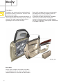
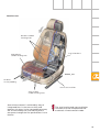
Seats
Backrest adjustment –
The angle of the top 1/3 of the
backrest can be adjusted by 15°
for enhanced shoulder comfort.
Lumbar support with massage
function over a length of 60 mm
Crash-active, electronic
head restraint with 70 mm height
adjustment
Thorax/pelvis
side airbag
Backrest fan
SSP282_116
Electric seat depth adjustment – As the
structure moves forwards it pulls the
padding with it and so extends the seat
area by 50 mm.
Seat cushion fan
A new seat concept was developed for the
Audi A8 ´03.
The basic seat features the following
standard functions:
Extra features of sports and comfort seats:
– Electric seat length, height and angle
adjustment
– Electric backrest angle adjustment
– Front crash-active head restraints (refer to
Page 21)
Optional extras for comfort seat:
The basic seat can additionally be fitted with
– Four-way lumbar support
– Seat memory for driver and front
passenger
– Electrically adjustable head restraints
– Electric belt height adjusters
– Electric top 1/3 backrest adjustment
– Electric seat depth adjustment
– Climate function (refer to Page 85)
– and/or massage function
The massage function is implemented by way
of rhythmic action of the electromechanical
lumbar support, thus massaging and relaxing
the back muscles.
The fixed rear seat bench versions correspond
to those of the front seats, with the third head
restraint being fully retractable. Electric
individual seats are however only available as
"Basic" and "Comfort" versions.
13
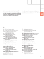
Passenger Protection
System layout
G 284
G 283
K145
AIRBAG
J623
OFF
J285/K75
AIRBAG
E224
AUS EIN
T16
J533
N95/G85
N131
J234
E24
E25
J526
N199
G179
N200
N154
N153
N201
N251
G180
N202
N196
N198
N252
N197
G 256
G 257
J393
J655
14
SSP282_068
Use is made in the Audi A8 ´03 of the 8.4E+
The wide range of sensors permits detection
airbag system with the aim of attaining greater not only of head-on collision and side impact,
occupant safety whilst reducing the impact.
but also of rear-end collisions.
This was achieved, for example, by way of twostage front airbag triggering, active front head
restraints and a battery cut-off element.
Key
E24 Driver side belt switch
E25 Front passenger side belt switch
E224 Airbag disabling key switch,
front passenger side
G85 Steering angle sender
G179 Side airbag crash sensor,
driver side (B-pillar)
G180 Side airbag crash sensor,
front passenger side (B-pillar)
G256 Rear side airbag crash sensor,
driver side
G257 Rear side airbag crash sensor,
front passenger side
G283 Front airbag crash sensor,
driver side
G284 Front airbag crash sensor,
front passenger side
K75 Airbag warning lamp
K145 Airbag disabled warning lamp,
front passenger side
N95
N131
N153
N154
N196
N197
N198
N199
N200
N201
J234 Airbag control unit
J285 Control unit with display
in dash panel insert
J393 Convenience system central
control unit
J526 Telephone/telematics control unit
J533 Data bus diagnostic interface
(gateway)
J623 Engine control unit
J655 Battery cut-off relay
N202
N251
N252
T16
Driver side airbag igniter
Airbag igniter 1, front passenger side
Belt tensioner igniter 1, driver side
Belt tensioner igniter 2,
front passenger side
Rear belt tensioner igniter,
driver side
Rear belt tensioner igniter,
front passenger side
Rear belt tensioner igniter,
centre
Side airbag igniter, driver side
Side airbag igniter,
front passenger side
Rear side airbag igniter,
driver side
Rear side airbag igniter,
front passenger side
Curtain airbag igniter, driver side
Curtain airbag igniter,
front passenger side
16-pin connector
(diagnostic connection)
15
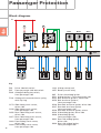
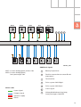
Passenger Protection
Block diagram
15
3
1
G283
G284
G179
J655
E224
2
J234
F138
N95
N131
N199
N200
N201
N202
Key
E24 Driver side belt switch
E25 Front passenger side belt switch
E224 Airbag disabling key switch,
front passenger side
F138 Airbag coil connector/return spring
with slip ring
16
G179 Side airbag crash sensor,
driver side
G180 Side airbag crash sensor,
front passenger side
G256 Rear side airbag crash sensor,
driver side
G257 Rear side airbag crash sensor,
front passenger side
G283 Front airbag crash sensor,
driver side
G284 Front airbag crash sensor,
front passenger side
J234 Airbag control unit
J655 Battery cut-off relay
N95
N131
N153
N154
N196
N197
N198
N199
N200
N201
N202
Driver side airbag igniter
Airbag igniter 1, front passenger side
Belt tensioner igniter 1, driver side
Belt tensioner igniter 2,
front passenger side
Rear belt tensioner igniter, driver side
Rear belt tensioner igniter,
front passenger side
Rear belt tensioner igniter, centre
Side airbag igniter, driver side
Side airbag igniter,
front passenger side
Rear side airbag igniter,
driver side
Rear side airbag igniter,
front passenger side
G180
G256
G257
E24
E25
4
N251
N252
N153
N154
N196
N198
5
6
7
N197
SSP282_069
Additional signals
N251 Curtain airbag igniter, driver side
N252 Curtain airbag igniter,
front passenger side
1
Battery A (positive)
2
Positive connection to starter B and
alternator C
3
Terminal 58s
4
Drive system CAN (High)
5
Drive system CAN (Low)
6
Crash signal
7
Airbag disabled warning lamp,
front passenger side K145
Colour code
= Input signal
= Output signal
= Positive supply
= Earth
17
Passenger Protection
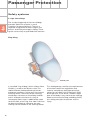
Safety systems
2-stage front airbags
The 2-stage triggering of the front airbags
provides optimum restraint in crash
situations at around 30 km/h. There is a
separate firing pellet for each stage in the
driver's and front passenger's airbag. These
ignite successively at specified time intervals.
Ring airbag
SSP282_070
A so-called "ring airbag", which inflates like a
life belt, is used on the driver's side. This
radial inflation method affords particular
protection to drivers sitting very close to the
steering wheel. The centre of the steering
wheel does not move as the airbag unfolds
and is inflated in the form of a ring. A
rectangular fabric layer is additionally sewn
to three sides of the ring. One side is left free
to allow the airbag to slide over the nonmoving centre section of the steering wheel.
18
This airbag design satisfies the requirements
of the latest American legislation and
involves compliance with biomechanical
values for so-called "Out Of Position" (OOP)
driver posture. If the driver's head or upper
part of the body is very close to the steering
wheel at the time of airbag unfolding (OOP),
this airbag concept can prevent serious
injury.
Front passenger's airbag deactivation
An optional feature of the Audi A8 ´03 is a new
airbag disabling key switch for the front
passenger's side E224.
Two resistance paths are integrated into this
switch to permit detection of individual faults.
A fault in the key switch is indicated by
flashing of the front passenger's side airbag
disabled warning lamp K145 located in the
centre console next to the hazard warning
switch.
SSP282_081
Front knee airbags (USA)
SSP282_114
The USA version of the Audi A8 ´03 is fitted
with driver's and front passenger's knee
airbags as standard, thus optimising driver
and front passenger movement in a crash
situation.
In this way, severe impact in the knee zone is
avoided.
Knee airbags are required by legislation in the
USA.
19
Passenger Protection
Detection of rear-end collision
Rear-end collisions are detected by way of a
sensor in the airbag control unit J234 and a
plausibility function involving the driver's and
front passenger's front airbag crash sensors
G283 and G284.
Up-front sensors
For the first time, use is made in the
Audi A8 ´03 of so-called up-front sensors.
These take the form of two additional frontend acceleration sensors on the right and left
beneath the corresponding headlight.
SSP282_072
Lateral acceleration sensors
Further acceleration sensors are
located at the B and C-pillars.
C-pillar sensor
B-pillar sensor
SSP282_073
20
Active head restraints
The front seats of the Audi A8 ´03 are provided
with active head restraints.
With this system, the head restraints move
forwards in the event of a rear-end collision to
shorten the distance between head and
restraint.
The danger of cervical vertebrae injury is
greatly diminished by reducing the relative
acceleration between shoulder and head.
In head-on collision situations, the mechanics
of centrifugal weight are neutralised.
SSP282_082
Belt tensioners
Five belt tensioners are fitted as standard.
There is no centre belt tensioner if the rear
seats are electrically adjustable.
21
Passenger Protection
Battery cut-off relay J655
The battery cut-off relay is a battery isolating
element designed to disconnect starter and
alternator power from the electrical system in
the event of a crash.
Terminal
Pin
Input/output
Description
30, battery
A
Input
(screw connection)
Ubat. term. 30/battery
87
B
Output
(screw connection)
Output
Terminal 15
1
Input
(plug connection)
Positive power supply,
interruptible
Vehicle earth
2
Input
(plug connection)
Earth from
airbag control unit J234
Crash signal
3
Input
(plug connection)
Crash signal from
airbag control unit J234
Diagnosis
4
Input
(plug connection)
Diagnostic wire from
airbag control unit J234
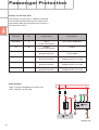
Block diagram
J644 Energy management control unit
J655 Battery cut-off relay
30
15
4
3
1
A
+
J655
B
2
J644
31
SSP282_076
22
Fitting location
The battery cut-off relay is located in front of
the battery.
Triggering
SSP282_083
The airbag control unit J234 provides the
battery cut-off element with the triggering
command via a discrete wire.
Triggering of this element by the airbag
control unit causes a white panel to appear in
the element window instead of a copper coil.
Following isolation, the battery cut-off
element can be manually reset by way of the
yellow knob.
Control element test
The control element test in the airbag control
unit also triggers the battery cut-off relay. It
should be ensured that the relay is manually
reset, as otherwise the battery cannot be
charged.
SSP282_079
Window
Reset knob
SSP282_077
23
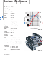
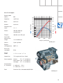
Engine, Mechanics
Technical data
V8 4.2 l 5V engine
4,172
Bore:
84.5 mm
Compression
ratio:
Power:
Torque:
93.0 mm
11 : 1
246 kW (335 hp)
at 6,500 rpm
430 Nm at 3,500 rpm
Camshaft
adjustment
range:
22° CS advance
Valves:
5 per cylinder
Engine
management:
ME7.1.1
Emission
standard:
EU 4
Firing
order:
1-5-4-8-6-3-7-2
Capacities:
7.5 l engine oil (incl. filter)
Consumption:
Urban:
17.5 - 17.6 l/100 km
Non-urban: 8.7 - 8.8 l/100 km
Average: 11.9 - 12.0 l/100 km
Acceleration
0 - 100 km/h:
Fuel:
CS = Crankshaft
460
240
440
220
420
200
400
180
380
160
360
140
340
120
320
100
300
80
280
60
260
40
2000
4000
Power [kW]
cm3
Capacity:
Stroke:
24
BFM
Torque [Nm]
Engine code
letters:
6000
Engine speed [rpm]
SSP282_002
0 - 80 km/h – 4.8 s
0 - 100 km/h – 6.3 s
Premium Plus Unleaded
98/95 RON
SSP282_012
BFL
Capacity:
3,697 cm3
Bore:
84.5 mm
Stroke:
Compression
ratio:
Power:
Torque:
82.4 mm
11 : 1
206 kW (280 hp)
at 6,000 rpm
360 Nm at 3,750 rpm
Camshaft
adjustment
range:
13° CS advance
Valves:
5 per cylinder
Engine
management:
ME7.1.1
Emission
standard:
EU 4
Firing
order:
1-5-4-8-6-3-7-2
Capacities:
7.5 l engine oil (incl. filter)
Consumption:
Urban:
17.1 - 17.3 l/100 km
Non-urban: 8.6 - 8.8 l/100 km
Average: 11.7 - 11.9 l/100 km
Acceleration
0 - 100 km/h:
Fuel:
460
240
440
220
420
200
400
180
380
160
360
140
340
120
320
100
300
80
280
60
260
40
2000
4000
Power [kW]
Engine code
letters:
Torque [Nm]
V8 3.7 l 5V engine
6000
Engine speed [rpm]
SSP282_001
0 - 80 km/h – 5.6 s
0 - 100 km/h – 7.3 s
Premium Plus Unleaded 98/95 RON
SSP282_011
25
Engine, Mechanics
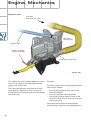
V8 5V 3.7 l/4.2 l engine
The 3.7 l and 4.2 l V8 engines were adopted
from the predecessor model with certain
modifications.
Design and operation are described in
SSP 217.
These modifications relate to the intake and
exhaust systems and are described in the
following.
Variable-intake manifold in 4.2 l engine
This takes the form of a 2-stage variable-intake
manifold made of a die-cast magnesium alloy,
bonded and bolted together in four sections.
The intake manifold must be replaced as
a complete unit when performing
repairs.
The two-stage design permits the use of two
intake paths with large cross section.
SSP282_013
26
– Long intake path, 705 mm
– Changeover flap closed for high torque
SSP282_014
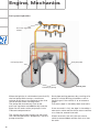
Each of the two splined shafts is fitted with
four flaps per cylinder bank.
The shape of the rubber-encased flaps
ensures unimpeded air flow in the torque
position and reliable power position sealing
of the duct. This is a prerequisite for
utilisation of the gas-dynamic resonance
effects. In the power position, the backs of
the flaps take on the shape of the duct wall,
thus allowing low-resistance intake air flow
into the cylinders.
Mechanical couplings provide a link with the
vacuum units for adjustment of the two
shafts and thus the intake manifold flaps.
SSP282_016
– Short intake path, 322 mm
– Changeover flap open for high power
with high air throughput
Changeover from long to short at 4,480 rpm
Changeover from short to long at 4,320 rpm
SSP282_015
27
Engine, Mechanics
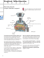
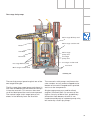
Variable-intake manifold in 3.7 l engine
Changeover flap, stage 3
Intake air (inlet)
t
nic
o
ctr e
ele valv
m e
Fro rottl
Th
Vacuum unit
Changeover flap, stage 3
o
hr
ttl
e
Injector
mounts
Changeover flap, stage 2
(open)
Vacuum unit
Changeover flap, stage 2
Resonance tube, cyl. 5
(inlet end)
This is the same 3-stage variable-intake
manifold as previously fitted in the V8 engine.
Due to the piston stroke of only 82.4 mm,
three resonance tube lengths are required to
achieve resonance effects in the lower engine
speed range.
Changeover points:
Operation of the 3-stage variable-intake
manifold is described in SSP 217.
28
SSP282_017
– Long to short
at 3,280 rpm
– Short to long
at 3,120 rpm
– Short to shorter
at 5,120 rpm
– Shorter to short
at 4,920 rpm
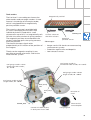
Air cleaner
A round filter is employed instead of a flat filter
to achieve a larger filter surface area for more
air throughput in view of the different amount
of space available.
SSP282_018
Furthermore, an additional intake air flap in the
air cleaner is opened as a function of load at
engine speeds as of 3,000 rpm to attain the
large volume of air required at full throttle. This
flap enables additional air to be drawn in from
the engine compartment and reduces the air
velocity in the air cleaner.
SSP282_019
29
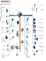
Engine, Mechanics
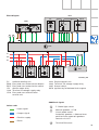
Fuel pump relay J17
Fuel pump G6
System layout
Fuel pump II relay J49
Fuel pump G23
Actuators/sensors
Engine control unit J623
Hot-film air-mass meter G70
Engine speed sender G28
Injectors N30, N31, N32, N33 (bank 1)
Hall sender G40 (bank 2) and
Hall sender 2 G163 (bank 1)
Lambda probe G39
(bank 1)
Lambda probe II G108
(bank 2)
Lambda probe after catalyst G130
(bank 1)
Lambda probe II after catalyst G131
(bank 2)
Pedal position sender/accelerator
pedal module with accelerator pedal
position sender G79 and accelerator
pedal position sender 2 G185
Injectors N83, N84, N85, N86 (bank 2)
Intake manifold changeover valve
N156 and
Intake manifold changeover valve 2
N261
Steering
angle sender G85
Ignition coils N (no. 1 cyl.), N128 (no. 2 cyl.),
N158 (no. 3 cyl.), N163 (no. 4 cyl.)
Automatic
gearbox
control unit J217
Brake light switch F and
Brake pedal switch F47
Ignition coils N164 (no. 5 cyl.), N189 (no. 6 cyl.),
N190 (no. 7 cyl.), N191 (no. 8 cyl.)
Left electrohydraulic engine mounting
solenoid valve N144 and
Right electrohydraulic engine mounting
solenoid valve N145
Activated charcoal filter system solenoid
valve 1 N80
Throttle valve control
part J338 with
Throttle valve drive G186
(electric power control)
Throttle valve drive angle sender 1 G187
Throttle valve drive angle sender 2 G188
ESP
control unit J104
Clutch pedal switch F36
(manual gearbox only)
Secondary-air pump relay J299 and
Secondary-air pump motor V101
Torque rod valve N382
Secondary air inlet valve N112
Coolant temperature sender G62
Knock sensor I G61 (bank 1) and
Knock sensor II G66 (bank 2)
Additional signals:
– Air conditioner requirement
– Cruise control switch
– Term. 50, stage 1
– Automatic gearbox selector lever position
30
Dash panel
insert CAN
Control unit with display in dash
panel insert J285
Data bus diagnostic
interface J533
Airbag
control unit J234
Drive system CAN
Diagnosis CAN
Lambda probe heater Z19
(bank 1) and
Lambda probe 2 heater Z28
(bank 2)
Throttle valve control part J338
With throttle valve drive G186
Inlet camshaft timing adjustment valve 1
N205 (bank 1)
Lambda probe 1 heater
after catalyst Z29
Lambda probe 2 heater
after catalyst Z30
Additional signals:
– Starter relay term. 50, stage 2
– Tank leakage pump (USA only)
– Air conditioner compressor (out)
and
N208 (bank 2)
SSP282_091
Engine, Mechanics
Fuel pump relay J17
Fuel pump G6
System layout
Fuel pump II relay J49
Fuel pump G23
Actuators/sensors
Engine control unit J623
Hot-film air-mass meter G70
Engine speed sender G28
Injectors N30, N31, N32, N33 (bank 1)
Hall sender G40 (bank 2) and
Hall sender 2 G163 (bank 1)
Lambda probe G39
(bank 1)
Lambda probe II G108
(bank 2)
Lambda probe after catalyst G130
(bank 1)
Lambda probe II after catalyst G131
(bank 2)
Pedal position sender/accelerator
pedal module with accelerator pedal
position sender G79 and accelerator
pedal position sender 2 G185
Injectors N83, N84, N85, N86 (bank 2)
Intake manifold changeover valve
N156 and
Intake manifold changeover valve 2
N261
Steering
angle sender G85
Ignition coils N (no. 1 cyl.), N128 (no. 2 cyl.),
N158 (no. 3 cyl.), N163 (no. 4 cyl.)
Automatic
gearbox
control unit J217
Brake light switch F and
Brake pedal switch F47
Ignition coils N164 (no. 5 cyl.), N189 (no. 6 cyl.),
N190 (no. 7 cyl.), N191 (no. 8 cyl.)
Left electrohydraulic engine mounting
solenoid valve N144 and
Right electrohydraulic engine mounting
solenoid valve N145
Activated charcoal filter system solenoid
valve 1 N80
Throttle valve control
part J338 with
Throttle valve drive G186
(electric power control)
Throttle valve drive angle sender 1 G187
Throttle valve drive angle sender 2 G188
ESP
control unit J104
Clutch pedal switch F36
(manual gearbox only)
Secondary-air pump relay J299 and
Secondary-air pump motor V101
Torque rod valve N382
Secondary air inlet valve N112
Coolant temperature sender G62
Knock sensor I G61 (bank 1) and
Knock sensor II G66 (bank 2)
Additional signals:
– Air conditioner requirement
– Cruise control switch
– Term. 50, stage 1
– Automatic gearbox selector lever position
30
Dash panel
insert CAN
Control unit with display in dash
panel insert J285
Data bus diagnostic
interface J533
Airbag
control unit J234
Drive system CAN
Diagnosis CAN
Lambda probe heater Z19
(bank 1) and
Lambda probe 2 heater Z28
(bank 2)
Throttle valve control part J338
With throttle valve drive G186
Inlet camshaft timing adjustment valve 1
N205 (bank 1)
Lambda probe 1 heater
after catalyst Z29
Lambda probe 2 heater
after catalyst Z30
Additional signals:
– Starter relay term. 50, stage 2
– Tank leakage pump (USA only)
– Air conditioner compressor (out)
and
N208 (bank 2)
SSP282_091
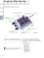
Engine, Mechanics
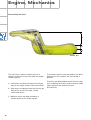
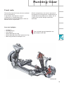
Electrohydraulic
torque reaction support
Stress-free alignment of the torque reaction
support is implemented by way of the lock
nut.
Lock nut
Isolation
diaphragm
Shell
Upper section of
nozzle plate
Top section
Plastic ring with sheet metal ring
Connecting
pipe
Solenoid
Bellows cap
SSP282_020
Bottom
section
The purpose of torque reaction support is to
cushion the drive shaft and propshaft torque.
The position of the support bearing at the
front right of the engine is ideal, as this is
where the engine motion resulting from drive
shaft and propshaft torque accumulates.
The torque reaction support is divided into
two halves by the plastic ring, the sheet metal
ring and the isolation diaphragm. Both halves
are filled with fluid (glycol). The isolation
diaphragm is flexibly linked to the plastic and
sheet metal rings.
If the torque reaction support is subjected to
load, the fluid can be displaced between the
top and bottom section by way of a
connecting pipe, the dimensions of which are
such that it acts as a restrictor as of a defined
frequency.
32
When the solenoid is deenergised, vibration
causes the plastic ring with sheet metal ring
and isolation diaphragm to oscillate as well.
The moments are damped slightly and thus
transmitted to a lesser extent to the body.
As of an engine speed of approx. > 1,100 rpm
and a vehicle speed of > 5 km/h, the solenoid
is energised and attracts the sheet metal ring
together with the plastic ring.
This restricts the movement of the isolation
diaphragm, which can then only vibrate
slightly. In this case there is a high level of
vibration damping and the torque reaction
support is "hard".
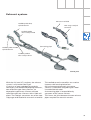
Exhaust system
Exhaust manifold
Lambda probe G39,
cylinder bank 1
Two-stage catalytic
converter
Lambda probe
after catalyst G130
Connecting pipe
Lambda probe II G108,
cylinder bank 2
Lambda probe II
after catalyst G131
SSP282_028
With the 4.2 l and 3.7 l engines, the exhaust
system is of the dual-flow type.
It consists of two underbonnet catalytic
converters, two flexible decoupling elements,
two reflection-type front silencers, an
absorption-type centre silencer and two
reflection-type rear silencers with visible tail
pipes. The catalytic converters are of the twostage type and fitted with a ceramic monolith.
Thin-walled ceramic monoliths are used to
improve cold starting behaviour.
On environmental grounds, the centre
silencer is fitted with long-fibre glass wool
instead of basalt wool.
A connecting pipe is located directly
upstream of the centre silencer.
This forms the joint between the two exhaust
pipes required for acoustic reasons.
33
Engine, Mechanics
Fuel tank
The fuel tank capacity is approximately
90 litres.
The basic unit consists of two plasma-welded
stainless steel shells. There are no differences
between petrol and diesel engine versions.
The tubing system for the tank breather at the
filler pipe has been considerably simplified as
compared to the predecessor model. With the
exception of diesel vehicles, the pipe
connections have been converted to quickrelease couplings.
The filler neck is a single piece and welded to
the basic unit. For reasons of crash safety, the
centre section of the filler neck takes the form
of a corrugated tube.
A new feature is the use of a 2-stage delivery
pump for each tank chamber in
separate reservoirs.
In crash situations, this section is subject to
defined deformation to prevent cracks and
fuel spillage.
The fuel level is measured by two immersion
tube senders combined with two angle
senders.
To create the best possible ergonomic
conditions for the rear passengers in
combination with maximum luggage
compartment volume, the two tank
compartments are shallower than in the
predecessor model.
The additional expansion tank has been taken
out of the filler pipe and moved to the fuel
tank.
Activated charcoal filter
Fuel filler neck
The switch from plastic to stainless steel
was necessary for compliance with
American LEV II legislation, which
demands a further significant reduction in
permissible emission levels.
Tank
compartment
breather
Diagnostic
connection
SSP282_007
34
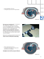
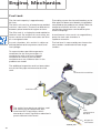
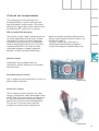
Interior of fuel tank (filling)
Float-type shutoff valve
Filler pipe
Breather pipe
to filler pipe
Reservoir
with pump unit, right
Reservoir
with pump unit, left
Baffle housing
of expansion tank
SSP282_006
Overflow channel
The fuel is conveyed via the filler pipe into the
right tank chamber (as viewed in direction of
travel). The fuel passes via an additional
overflow channel at the end of the filler pipe
predominantly into the right pump reservoir.
Use of the small overflow channel ensures
that even small quantities of fuel (e.g. filling
from canister) pass directly into the pump
reservoir.
The breather function for the side
compartments is provided by two breather
pipes to the main chamber.
Routing the filler pipe beneath the
longitudinal member means that the lowest
point of the pipe is not at the connection to
the fuel tank, thus producing a siphon effect.
A residual quantity of fuel remains in the filler
pipe. This necessitates a separate pipe to the
filler neck for the main chamber breather
function and for OBD II leakage diagnosis.
When the tank is full, the filler hose is closed
by a float-type shutoff valve at the end of the
filler pipe.
35
Engine, Mechanics
Expansion tank
Inlet pipe
from tank filler neck
Float-type
rollover valve
Breather pipe
Suction jet pump
intake connection
Float-type shutoff valve
SSP282_009
The expansion tank (capacity approx. 2 litres)
consists of a plastic housing clipped to the
upper shell of the tank.
The internal expansion tank houses a floattype rollover valve and a small suction jet
pump which constantly pumps the tank empty
whilst driving.
Function
The main functions of the float-type rollover
valve are as follows:
– Closing-off of pipe to filler neck in the
event of rollover
– Closing in dynamic driving mode
– Closing by rising of float in valve in the
event of a brief excess of fuel in the tank
due to sloshing
Closing-off of the pipe to the activated
charcoal filter stops fuel overflowing into it.
36
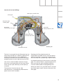
Two-stage fuel pumps
Main stage delivery end
Main stage suction end
Return
Overflow
Reservoir
Main stage
pump unit
Pre-stage
pump unit
Pre-stage suction end
Pre-stage delivery end
Fuel tank
Main stage suction end
SSP282_003
The two fuel pumps (petrol engine) are of the
two-stage flow type.
The first stage (pre-stage) pump unit draws in
fuel from the bottom of the tank and conveys
it into the reservoir. This ensures that even
small residual quantities can be transported.
The second stage (main stage) pump unit
draws in fuel directly from the reservoir.
The reservoirs with pumps and immersion
tube senders rest on and are clipped to the
bottom of the tank. Flanged covers provide
access to the components.
Single-stage pumps are used for diesel
engines (Common Rail). On account of the
higher viscosity of diesel fuel, pre-delivery
(extraction from bottom of tank) is not
implemented by way of separate pump units,
but rather by suction jet pumps.
37
Engine, Mechanics
Fuel system (hydraulics)
Pressure regulator
(4 bar)
Fuel pump G23
Fuel pump G6
Suction jet pump
When the ignition is switched on (terminal 15),
the fuel pump G23 conveys a maximum
volume to the pressure regulator at the fuel
rail to achieve short starting times.
The pump G6 also conveys fuel to the
pressure regulator and additionally into the
pipes for the two suction jet pumps in the
side tank compartments.
The suction jet pumps convey the fuel from
the side compartments "diagonally" into the
pump reservoirs.
38
SSP282_005
Such pipe routing prevents dry running of a
pump in critical driving situations such as
cornering or if the vehicle is at an extreme
angle.
The return pipe is shared by both reservoirs.
If one reservoir is full, the pipe is closed by a
non-return valve and the entire return volume
runs into the second reservoir.
If both reservoirs are full, the non-return
valves are overridden and the fuel runs into
the tank.
Tank senders
Magnetically soft foil
The fuel level is sensed by two immersion
tube senders and two angle senders. A new
feature is the design of the angle sender,
which is equipped with a magnetically
passive position sensor.
The ceramic substrate is provided with
51 series-connected film resistors with
individual pick-off. Fitted with a small
clearance on top of this is a magnetically soft
foil with the same number of spring contacts.
The magnetic position sensor beneath the
ceramic substrate pulls the spring contacts
onto the pick-offs.
The electrical output signal varies
proportionally as a function of the position of
the magnet.
Thanks to the magnetic coupling it was
possible to provide a hermetic seal for the
measurement system.
SSP282_010
Ceramic substrate
with film resistors
Magnetic
position sensor
Advantages:
– Longer service life thanks to noncontacting
measurement system
– Protection against dirt and deposits
– Low contact currents
Fuel gauge sender G
(immersion tube sender, 70 - 158 W)
Fuel gauge sender 3 G237
(immersion tube sender,
70 - 158 W)
Fuel gauge sender 2 G169
(angle sender, 50 - 300 W)
Fuel gauge sender 4 G393
(angle sender, 50 - 300 W)
Fuel pump
G23
Fuel pump
G6
Direction of
travel
SSP282_008
Characteristic
curve adaption
Control unit with display
in dash panel insert J285
Fuel gauge G1
39
Engine, Mechanics
Determining fuel level
b
c
a
SSP282_004
The fuel level is determined by way of a
logical system of immersion tube and angle
sender signals.
The sender signals are evaluated by the dash
panel insert. All senders are connected in
parallel.
a - Low levels are determined exclusively by
way of the angle sender measured values
The wires are bunched beneath the fuel tank,
thus enabling resistance measurements to be
taken without the need for further
dismantling.
b - High levels are determined exclusively by
way of the immersion tube sender
measured values.
c - Medium levels are determined by a
combination of all sender signals
40
Automatically controlled
starting
The automatic start control is integrated into
the engine control unit.
A new feature is that starter control is no
longer implemented by way of the ignition/
starter switch D (switching of terminal 50),
but rather it is performed automatically by
the engine control unit.
Release for starter actuation is always
transmitted by the entry and start
authorisation control unit J518 to the engine
control unit J623.
In addition to general release by the
immobilizer, the following start release
conditions also have to be satisfied:
– Start signal from entry and start
authorisation switch E415 or entry and
start authorisation button E408
– 1 Clutch pedal pressed, signal from clutch
pedal switch F194 (manual gearbox only)
1
– 1 Selector lever position P or N (automatic
gearbox control unit J217)
– 2 In the event of start signal via entry and
start authorisation button E408, brake
must be pressed (signal from brake light
switch F via separate interface)
2
As a safeguard, P/N signal or signal from
clutch pedal switch F194 must be applied
to the separate interfaces of the two
control units (J623 and J518).
Additional safeguard, as entry and start
authorisation button E408 can be
actuated by front passenger.
41
Engine, Mechanics
Sequence of operations
1 Entry and start authorisation switch E415/
entry and start authorisation button E408
The driver triggers a brief start signal
(min. 20 ms) by turning the ignition key to
start position or by pressing the entry and
start authorisation button E408.
2 Entry and start authorisation control unit
J518
The entry and start authorisation control
unit checks for authorisation – in the form
of information on selector slide position N
or P – from the automatic gearbox control
unit J217 and for brake application in the
case of a start signal from the entry and
start authorisation button E408.
If the start prerequisites have been
satisfied, the entry and start authorisation
control unit J518 transmits a start request
– terminal 50 ON – to the engine control
unit J623.
The entry and start authorisation control
unit J518 also controls the terminal 15 and
terminal 75x circuits.
3 Engine control unit J623
Application of selector slide position P/N or
"clutch pressed" information to the engine
control unit (separate interface) causes the
two starter relays J53 and J695 to be
actuated simultaneously. The relays then
switch terminal 50 for starter actuation.
The starter operates and cranks the engine.
On exceeding a defined engine speed, the
engine control unit J623 recognises that
the engine has started and the relays are
deenergised (thus terminating starting
process).
As a safeguard, two relays are connected in
series. In the event of fusion welding of the
make contacts (relay remains closed
following deenergisation), the engine
control unit J623 can thus interrupt the
circuit (terminal 50) by way of the other
relay in each case.
The two relays are deenergised alternately
in order to ensure even make contact wear
(break spark) in both relays. The
deenergisation sequence alternates.
42
Relay operation is monitored and faults
diagnosed by evaluating the alternating
deenergisation with the aid of the terminal
50R interface.
The terminal 50R interface represents a link
with terminal 50 and provides the engine
control unit J623 with feedback for start
control/diagnosis.
Automatically controlled starting is not
permitted in the event of undervoltage or a
system fault.
The engine can however be started
manually by way of corresponding start
signal actuation.
To relieve the load on the starter and
battery, the relay actuation time is
limited to approx. 10 seconds per starting
operation (automatic or manual starting).
Block diagram
E415
N376
D1
E408
2 1 0
STOP
1
6x
2 1 0
START
2
58s
J518
50R
15
1
2
75x
30
50R
3
J623
J329
D1
E408
E415
J53
J329
J518
J694
J53
Inhibitor reading unit
Entry and start authorisation button
Entry and start authorisation switch
Starter motor relay
Terminal 15 voltage supply relay
Entry and start authorisation
control unit
J695
J623
J694
J695
N376
SSP282_024
Engine control unit
Terminal 75x voltage supply relay
Starter relay 2
Ignition key withdrawal lock magnet
Additional signals
Colour code
= Input signal
1
F - Brake light switch
2
Manual gearbox -> F194
Clutch pedal switch
Automatic gearbox -> Selector lever
position from automatic gearbox
control unit J217
3
Terminal 50/starter
= Output signal
= Positive supply
= Earth
43
Engine, Mechanics
Explanatory notes on internal control unit
sequence chart
Request for starting (terminal 50 ON from
entry and start authorisation control unit
J518) energises the two relays. Locking-in
takes place during the initialisation phase of
engine control unit J623.
After initialisation, the engine control unit
assumes further starter control tasks as described
under item 3.
Term. 15
Start request from
driver authorisation
system
Engine start
recognition
(engine speed)
Start request retained manually
Start request briefly activated
Engine speed increases
Starter speed
Relay deenergisation
Relay deenergisation by
engine control unit
Starter operation feedback signal
Term. 50R/diagnosis
Engine control unit
initialisation
Locking-in
Engine control unit active
Engine control unit active
Starting
Engine running
Ignition on
SSP282_064
44
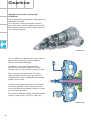
Gearbox
To satisfy high comfort requirements, the
Audi A8 ´03 features a new 6-speed automatic
gearbox capable of handling a high engine
torque of max. 600 Nm.
Two different versions are available:
– 420 Nm for the V8 5V 4.2 l or
3.7 l engine and
– 600 Nm for the V8 TDI 4.0 l or
6.0 l W12 engine
Design and operation of the 09E gearbox
are described in SSP 283 (Part 1) and
SSP 284 (Part 2).
SSP282_043
Technical data
Designation:
Factory
designation:
ZF
designation:
Type:
Control:
09E
Max. torque
transmission:
AL 600-6Q
600 Nm for
V8 TDI 4.0 l /W12
6.0 l engine
6HP-26 A61
6-speed planetary
gearbox, featuring electrohydraulic control
with hydrodynamic
torque converter and
slip-controlled lockup clutch
Via mechatronic system
(integration of hydraulic
control unit and
electronic control
to form one unit)
420 Nm for
V8 5V 4.2 l /3.7 l engine
Front/rear axle
torque distribution:
50/50
Gear oil capacity
(total):
10.4 litres ATF
Gear oil capacity
(replacement):
10 litres ATF
Total weight:
approx. 138 kg
(420 Nm version)
approx. 142 kg
(600 Nm version)
45
Gearbox
Highlights of automatic gearbox 09E
(AL 600-6Q)
The 6-speed planetary gearbox is based on the
Lepelletier principle.
This concept is characterised by harmonic
gear ratio steps and the implementation of six
forward gears and one reverse gear with only
five selector elements.
SSP282_044
Use is made in this gearbox of a new internal
gear oil pump featuring a lower delivery
volume and reduced leakage.
In addition, it was possible to achieve
optimisation of the oil supply with lower
leakage rates in the hydraulic control system.
The "stationary disconnection" function
reduces engine output when the vehicle is
stopped with a gear engaged by interrupting
power transmission.
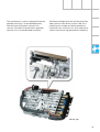
A particularly noteworthy feature of the 09E
automatic gearbox is the relocation of the
front-axle differential (flange shaft) to in front
of the torque converter.
The distance between flange shaft and engine
flange is now only 61 mm (01L = 164 mm).
SSP282_045
46
The mechatronic system integrated into the
gearbox housing is a new development,
combining the hydraulic control unit,
sensors, actuators and electronic gearbox
control unit in a coordinated assembly.
All data exchange with the vehicle periphery
takes place via the drive system CAN, thus
reducing the number of vehicle periphery
interfaces to a minimum (11 pins) and at the
same time enhancing operational reliability.
SSP282_046
47
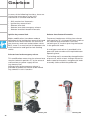
Gearbox
In terms of the following functions, there are
interesting new aspects to the shift
mechanism in the new Audi A8 '03:
–
–
–
–
–
Shift mechanism kinematics
Ignition key removal lock
Selector lever lock
Selector lever lock emergency release
Selector lever/lock button kinematics
Ignition key removal lock
Selector lever/button kinematics
Major modifications have been made to
operation of the ignition key removal lock and
selector lever lock (shiftlock). On account of
the new entry and start authorisation switch
E415, there is no mechanical link between the
shift mechanism and ignition lock (locking
cable).
To prevent inadvertent shifting into selector
lever position "S", a change has been made to
the selector lever kinematics such that
switching to "S" involves pressing the button
in the gearstick knob.
A small gear mechanism is provided in the
gearstick knob to reduce the required button
operating force.
Selector lever lock emergency release
The locking rod is actuated by the application
This modification means that the selector lever of pressure, which means changes have also
remains locked in position "P" in the event of
been made to kinematics and gearstick knob
malfunctions or power supply failure
assembly (refer to Workshop Manual).
(e.g. battery flat).
Selector lever lock emergency release is
provided to enable the vehicle to be moved
(e.g. towed) in such situations.
SSP282_048
48
SSP282_049
Running Gear
Front axle
The familiar four-link front axle was retained
for the Audi A8 '03.
A significant new feature is the air
suspension in combination with
electronically controlled dampers (refer to
Section on air suspension).
All axle components are new on account of
the geometric and kinematic modifications as
compared to the predecessor model, the air
suspension and the weight reductions
achieved.
Front axle highlights
–
–
–
–
–
–
Subframe
Auxiliary frame
Anti-roll bar
Wheel bearing housing
Wheel bearing with wheel speed sensing
Mounting bracket for damper unit
Front axle design and operation are
described in SSP 285.
SSP282_050
49
Running Gear
Rear axle
The rear axle is a more advanced version of
the familiar Audi A8 trapezium-link axle.
All axle components are new on account of
the geometric and kinematic modifications as
compared to the predecessor model, the air
suspension and the weight reductions
achieved.
Rear axle highlights
– Use of air suspension in conjunction with
electronically controlled damping
– Aluminium subframe to help
reduce weight
– Connection of anti-roll bar to trapezium
link
– Use of shorter track rod to reduce change
in toe on compression and extension of
suspension
– Use of ball studs to connect wheel bearing
housing and track rod, thus reducing
secondary spring rate
– Use of slotted bonded rubber bushes in
upper transverse link and connection
between trapezium link and subframe
50
Rear axle design and operation are
described in SSP 285.
SSP282_051
4-level air suspension
The introduction of the Audi A8 ´03 is
accompanied by a system featuring new
technical details and functions. The major
differences with respect to the familiar Audi
allroad quattro® system are as follows:
EDC instead of PDC damping
The control system makes allowance for the
currently applicable driving status. Wheel
movement (unsprung masses) and body
movement (sprung masses) are detected.
Various damping characteristic curves are
implemented within the scope of three
selectable programs (modes) and each
damper can be controlled individually.
Optimal comfort and road safety are thus
always guaranteed whichever mode is set
(comfort or sports).
The term "mode" thus describes a
coordinated combination of adaptive
suspension program and damping map.
Control concept
Integration into the MMI makes for
convenient, logical and easy to remember
control action.
Extended range of sensors
Use is made of three acceleration sensors to
detect body movement.
SSP282_052
External air springs
The air spring not only replaces the steel
spring, it also offers major advantages (refer
to SSP 242). The new external routing of the
air spring through an aluminium cylinder
permits the use of thinner-walled bellows.
This results in an even more sensitive
response to road surface irregularities.
SSP282_053
51
Running Gear
System layout
Rear axle
acceleration sensors
Control unit with
display in dash panel
insert J285
Front information and
display and operating
unit control unit J685
Rear axle
air suspension struts
Pressure
accumulator
Adaptive suspension
control unit
Front axle
air suspension struts
SSP282_054
Rear axle
level sensors
Front axle
level sensors
Solenoid valve block
Compressor
Front axle acceleration sensors
Design and operation of 4-level air
suspension are described in SSP 292.
52
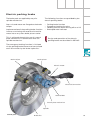
Electric parking brake
The brake pads are applied by way of a
spindle mechanism.
The following functions are provided by the
electric parking brake:
Gear unit and motor are flanged to the brake
caliper.
–
–
–
–
Implementation of the parking brake function
involves translating the rotation of the drive
motor into a very short brake piston stroke.
This is achieved through the use of a swash
plate mechanism in combination with the
spindle mechanism.
Parking brake function
Emergency braking function
Holding function when driving off on a hill
Brake pad wear indicator
Design and operation of the electric
parking brake are described in SSP 285.
The emergency braking function is initiated
via the parking brake button and transmitted
to all four wheels by the brake hydraulics.
Brake caliper
Brake piston
Electric motor
Electrical connection
Toothed belt
Swash plate mechanism
Spindle
SSP282_055
Brake disc
53
Running Gear
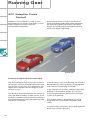
ACC (Adaptive Cruise
Control)
Adaptive Cruise Control is a new system
designed to assist drivers and offers a much
wider range of functions than the
conventional Tempomat.
Driver convenience is further enhanced, as
fewer accelerator and brake pedal operations
are required. Speed restrictions and safety
factors are reliably observed and the flow of
traffic thus better regulated.
SSP282_057
Summary of Adaptive Cruise Control (ACC)
The basic Adaptive Cruise Control function is
to maintain a driver-selectable distance from
the vehicle in front. ACC thus represents the
logical next step on from the original cruise
control system.
The distance from and speed of the vehicle in
front are determined by a radar sensor. If the
distance is greater than desired, the vehicle is
accelerated until the required speed input by
the driver is achieved.
If the distance is less than desired, the vehicle is
decelerated by reducing power, changing gear
and if necessary applying the brakes.
In the interests of comfort, maximum possible
braking is restricted to approx. 25 % of the
maximum deceleration potential of the brake
system (full braking).
The control action is designed to assist the
driver and thus contributes to greater road
safety.
In certain traffic situations, active braking by the
driver may still be necessary.
54
ACC system limits
Radar sensor
– ACC is designed to assist the driver and
is not a safety system.
– ACC is not a fully autonomous driving
system.
– ACC provides control in a speed range of
30 - 200 km/h.
– ACC does not react to stationary objects.
– Radar operation is impaired by rain,
spray and slush.
– Tight bends may restrict operation on
account of the limited radar detection
range.
An adapter plate permits fitting and
adjustment at a holder bolted to the centre of
the bumper bracket.
For details, refer to current Workshop Manual.
Design
Sender and control unit are integrated into
one housing - the distance regulation control
unit J428.
The entire assembly has to be replaced if the
control unit is defective.
Holder
Vertical
adjusting screw
Distance regulation
control unit J428 with
radar sensor
Mounting hole
SSP282_058
Horizontal
adjusting screw
55
Running Gear
Setting desired speed
The desired speed is the maximum speed to
be controlled by the ACC on an open road
(corresponds to cruise control system
function).
Pressing the SET button stores the current
speed as desired speed.
SSP282_061
The set speed is displayed by a bright red LED
in the speedometer rim and the "ACC active"
symbol appears in the speedometer.
The "ACC active" status is indicated by faint red
illumination of all LEDs in the range between
30 and 200 km/h.
SSP282_060
56
Setting desired distance
The desired distance from the vehicle in front
can be set by the driver in four stages. The
distance set by the ACC is governed by the
respective vehicle speed. The distance
increases with increasing vehicle speed.
The minimum setting ensures compliance
with the permissible safety distance when
travelling at a constant speed in traffic.
The desired distance from the vehicle in front
is set by means of the sliding switch on the
stalk. Actuation of the switch increases or
reduces the distance by one stage each time.
The desired distance selected determines the
vehicle acceleration dynamics.
SSP282_059
The chosen distance is briefly indicated on
the info line in the speedometer centre
display.
The centre display is activated the first time
the button is pressed.
The number of bars between the vehicles
displayed corresponds to the distance stage
selected in each case.
The distance stage can be set for each driver.
Design and operation of the ACC are
described in SSP 289 – Adaptive Cruise
Control.
Pay attention to operating instructions
and manuals.
SSP282_062
57
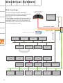
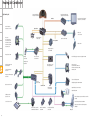
Electrical System
Bus topology
Distance regulation
control unit J428
Dash panel insert CAN
Adaptive cruise control
CAN
The increasing demand for additional
functions and convenience in the vehicle calls
for the use of ever more wide ranging
electronics.
The increased use of electronics also requires
a new approach to data transfer between the
individual control units. This also applies to
the Audi A8 ´03, in which more than 70 control
units have to communicate.
Control unit with
display in dash panel
insert J285
Electric park and
handbrake control
unit J540
Headlight range
control unit
J431
Engine control unit
J623
Airbag control unit
J234
Engine control
unit 2 J624
ABS with EDL
control unit
J104
Adaptive
suspension control
unit J197
Automatic gearbox
control unit
J217
Internal bus link
Anti-theft/
tilt system control
unit J529
Boot lid control unit
J605
Wiper motor control
unit J400
Garage door
operation control
unit J530
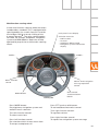
Multifunction
steering wheel
E221
Convenenience
system central
control unit J393
On-board power
supply control unit
J519
On-board power
supply control unit 2
J520
Steering column
electronics control
unit J527
Front passenger
side door
control unit J387
Rear left door
control unit J388
Rear right door
control unit J389
Seat adjustment
control unit
J136
LIN
Driver side door
control unit J386
58
Steering angle
sender G85
Front passenger
seat adjustment
control unit J521
Convenience CAN
Diagnostic connection T16
Drive system CAN
Diagnosis CAN
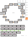
Rear DVD changer
R162
Telephone/
telematics control
unit J526
Control unit for rear
right
information display
and operating
unit J649
BluetoothTM
Telephone
handset
R37
Control unit for rear
left
information display
and operating
unit J648
Front information
display and operating
unit control unit J523
DSP control unit
J525
Data bus diagnostic
interface J533
Navigation system
control unit
J401
MOST bus
CD ROM drive
R92
TV tuner
R78
CD changer
R41
Digital radio
R147
Chip card reader
control unit
J676
Fresh-air blower
control unit
J126
Heated windscreen
control unit J505
Rear left footwell
heater element Z42
Radio module R
Rear right footwell
heater element Z43
Driver seat
ventilation
control unit J672
Front passenger
seat ventilation
control unit J673
LIN
Climatronic control
unit J255
Rear seat
adjustment with
memory control
unit J522
Trailer detector
control unit J345
Energy
management
control unit J644
Entry and start
authorisation
control unit J518
Rear Climatronic
control and
display unit E265
Tyre pressure
monitor control unit
J502
Sun roof electronics
control unit J528
Additional heater
control unit J364
Driver identification
control unit J589
Front passenger
side rear seat
ventilation
control unit J675
Sliding sun roof
motor V1
Auxiliary heating
radio controlled
receiver R64
Parking aid control
unit J446
LIN
Driver side rear seat
ventilation control
unit J674
SSP282_063
59
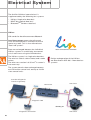
Electrical System
The familiar CAN bus (two-wire bus) is
supplemented by the following bus systems:
– LIN bus (single-wire data bus)
– MOST bus (optical data bus)
– BluetoothTM (wireless data bus)
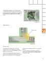
LIN bus
LIN stands for Local Interconnect Network.
Local Interconnect means that all control
units are located within a limited structural
space (e.g. roof). This is also referred to as
"local sub-system".
Data are exchanged between the individual
LIN bus systems in a vehicle by one control
unit in each case using the CAN data bus.
LOCAL INTERCONNECT NETWORK
The LIN bus system is a single-wire data bus.
The wire has a basic colour (violet) and a code
colour.
The wire cross-section is 0.35 mm2. A screen is
not necessary.
Design and operation of the LIN bus
are described in SSP 286 – New data bus
systems.
The system permits data exchange between
one LIN master control unit and up to 16 LIN
slave control units.
Data bus diagnostic
interface (gateway)
LIN slave 1
LIN master
Diagnosis CAN
SSP282_031
Diagnostic connection
60
LIN slave 2
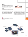
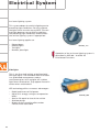
MOST bus
The term "Media Oriented Systems Transport"
signifies a network featuring media-oriented
data transport. This means that, in contrast to
the CAN data bus, address-oriented
messages are transmitted to a specific
receiver.
R
Media Oriented Systems Transport
This technique is used in Audi vehicles for the
transfer of infotainment system data.
The infotainment system offers a wide range
of modern information and entertainment
media. In addition to the familiar CAN bus
systems, use has been made for the first time
in the Audi A8 ´03 of an optical data bus
system.
The name of this data bus system is derived
from "Media Oriented Systems Transport
(MOST) Cooperation". This is an association
formed by various motor vehicle
manufacturers, their suppliers and software
companies with a view to developing
a standard high-speed data transfer system.
Design and operation of the MOST bus
are described in SSP 286 – New data bus
systems.
System manager
Sound system
Operating unit
SSP282_034
Display
61
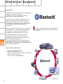
Electrical System
BluetoothTM
BluetoothTM is an internationally standardised
remote control data interface.
It permits control or monitoring of even
minute units using radio waves.
The primary aim when developing this new
type of interface was to create a wireless
alternative to cable links, which used to be
susceptible to interference and inconvenient
and frequently featured incompatible
connectors.
More and more manufacturers are making use
of "BluetoothTM" radio wave technology for
example for wireless interconnection of
notebook and mobile phone accessories.
Design and operation of the BluetoothTM
are described in SSP 286 – New data bus
systems.
As initiator and main contributor to the
development of this new transmission
technology, the Swedish company Ericsson
chose the name "Bluetooth".
The name originates from the Viking king
Harald Blåtand II (Danish, literally meaning
"Blue Tooth"), who lived around 1000 years ago
in Denmark and Norway.
Motor vehicle applications
–
–
–
–
–
Wireless telephone receiver
Wireless mobile phone
Hands-free unit with no additional adapters
Wireless internet access
Access for PCs and Notepads
SSP282_037
62
Vehicle electrical system
A major factor in terms of vehicle reliability is
one which is never even seen: the electrical
system.
Use is made for the Audi A8 ´03 of a customerspecific one-piece modular wiring harness.
"One-piece" means that power is supplied for
all essential electrical functions from a single
continuous wiring harness. The only isolating
points are at the doors, roof module and
engine.
"Customer-specific" means that each wiring
harness is designed to serve exactly the
equipment ordered by the customer. The
wiring harness is subdivided into individual
logic modules, each of which is responsible
for a clearly defined range of functions.
A plastic optical fibre is fitted for the
transmission of optical communication and
infotainment signals.
Its advantages as compared to a copper
conductor are its insusceptibility to
electromagnetic interference, a high
transmission capacity and less weight.
To achieve greater headroom, the wiring
harness to the roof module has been
extended to include the flexible flat cable
(FFC). This represents a new method of
solving the wiring problem in extremely
confined spaces (max. 2 mm between
headliner and body outer skin).
Design and operation of the optical fibre
are described in SSP 286 – New data bus
systems.
SSP282_038
63
Electrical System
Convenience and security
electronics
"Advanced Key" entry and start
authorisation system
"Advanced Key" can be taken to mean an
"advanced locking and security system".
It takes the form of a non-contacting key
recognition system. With the "Advanced Key"
package, the "Vehicle unlocking" and "Vehicle
locking" functions by way of a mechanical or
remote control key are supplemented by the noncontacting functions "Vehicle unlocking" and
"Vehicle locking".
Design and operation are described in
SSP 287 – Audi A8 ´03 Electrical
Components.
In addition, the driver can start the engine
with the START/STOP button (START/STOP
function) without inserting the ignition key
in the electronic ignition lock.
Functions
Advanced Key "unlocking"
The key owner enters the key detection zone next
to the vehicle (less than 1.5 m from door handle)
and reaches into the recessed handle moulding.
A proximity sensor starts a key scan by way of an
aerial.
The key responds by way of radio waves and the
vehicle is unlocked if authorised.
Advanced Key "starting"
The driver presses the start button, which again
initiates a key scan via the passengercompartment aerials near the selector lever, at the
rear centre vents and at the rear centre armrest.
The remote control key provides confirmation,
with the result that the ignition is switched on on
depressing the first stage of the start button and
the engine started on depressing the second
stage. The engine is switched off with the STOP
button.
SSP282_093
Advanced Key "locking"
SSP282_094
If the vehicle is to be locked from the outside, it is
sufficient to press the locking button in one of the
door handles. Actuation of the locking button
triggers a key scan via the door handle aerial and
the vehicle is locked on confirmation of the remote
control key.
64
SSP282_095
Multifunction steering wheel
A new multifunction steering wheel has been
introduced as standard. This is equipped with
special paddles (as used in formula 1 and for
the Le Mans R8) for manual shifting of the
6-speed Tiptronic®. The voice control option
for radio, CD changer, telephone, navigation
system and MMI address book can also be
operated by way of the multifunction steering
wheel.
Dash panel insert display
Selection menu for:
– Radio station
– CD track
– Telephone address book
– Navigation system information
display
Paddle –
Paddle +
Menu selection
control
Volume level/navigation
message repetition
control
MODE button
SSP282_086
Press MODE button:
For telephone, navigation system and
radio/CD menu selection
Turn left function control:
To select menu item
Press left function control:
For selection within chosen menu item
To accept a telephone call
Voice control
start/termination
button
Press PTT (push to talk) button:
To activate/deactivate voice control
Turn right function control:
To regulate volume
Press right function control:
To repeat last navigation system message
65
Electrical System
Infotainment
DVD - Video
DAB - Digital radio
Telephone
Telematics
Central display
and control
TV reception
CD/DVD navigation
Internet
Email
Minidisc/CD audio
Both in the modern business world and in the
private domain, mobile information and
entertainment are becoming ever more
important.
66
SSP282_090
In other words, vehicle occupants are becoming
increasingly interested in enjoying the benefits of
modern media.
With this in mind, the Audi A8 ´03 is fitted with
an infotainment system offering a wide range
of modern media.
Memory
CD 1
Source
Dire Straits - Brothers in …
Forward
Tr. 12
10:56
Manual
TP TMC D2 Private
Sound
SSP282_096
Design and operation are described in
SSP 293 - Audi A8 ´03 Infotainment.
67
Electrical System
Lighting system
Front lights
Parking light
(W5W/5 W bulb)
Adaptive light
(H8/35 W bulb)
Turn signal indicator
(2 x 16 W HPV bulb - yellow)
SSP282_056
Additional main beam
Headlight flasher
(H7/55 W bulb)
Reflector
for adaptive light
The headlight in the Audi A8 ´03 combines both
design elements and innovative technology.
Dipped beam/main beam
(Bi-Xenon/D2S - gas-discharge lamp)
Both bi-xenon versions feature an ellipsoid
module with a moving screen to achieve both
dipped beam and main beam with xenon light.
Headlight versions:
The automatic dynamic headlight range control
– Basic halogen version H7
represents a more advanced version of the
standard automatic control system. It provides
Dynamic headlight range control is not
headlight tilt compensation not only for various
necessary with halogen headlights. The air
load statuses but also as a dynamic function
suspension provides compensation for static reacting to differences in running gear
load statuses and a thumbwheel is therefore inclination caused by acceleration and
also not required.
deceleration.
– Bi-xenon version
– Bi-xenon version with integrated adaptive
light function
The headlight range control unit J431 is
responsible for providing static and dynamic
compensation for vehicle tilting as well as
actuation of the static adaptive light
function. The sensor signals of the 4-level air
suspension system are picked off by the
drive system CAN for control purposes. A
distinction is made between the two
gas-discharge lamp versions by way of
appropriate encoding (1 or 2) at the
headlight range control unit.
68
HPV stands for high-performance bulbs,
which are extremely compact and have a far
longer service life. They have a 25 % lower
power input than conventional bulbs. Such
bulbs cannot be replaced by customers.
The optional headlights with adaptive light
function are a clearly visible innovative feature
in the Audi A8 ´03. To implement this function,
the headlights are provided with an additional
reflector between dipped beam and main
beam.
SSP282_092
Light functions
Adaptive light
SSP282_087
Adaptive light
The additional reflector with a 35 W H8
halogen bulb is actuated as the situation
requires to ensure earlier perception of other
road users or obstacles.
When reversing or parking, both adaptive
lights are activated to provide the driver with a
better overall view of the surrounding area.
Control of the headlight functions is a complex
process.
It involves real time evaluation of several
signals (e.g. vehicle speed, steering angle and
turn signal indicator) by the headlight range
control unit J431.
69
Electrical System
Assistant lighting system
This system adapts the vehicle lighting to the
prevailing light conditions. For this purpose
the light switch must be set to AUTO. The rain
and light detector sensor G397 establishes
the prevailing light conditions and activates
the vehicle lighting system if appropriate.
Assistant lighting applies to:
–
–
–
–
Dipped beam
Parking lights
Tail lights
Number plate light
SSP282_110
Operation of the assistant lighting system is
described in SSP 288 – Audi A8 ´03
Distributed Functions.
Side lights
This is the first Audi vehicle to be fitted with
LED-type lights. The individual LEDs are fitted
in a graduated arrangement under a
transparent glass lens and give off a yellow
light when switched on. They appear neutral in
colour when switched off.
LED technology offers numerous advantages:
– Rapid attainment of full power
– Up to 50 % energy saving as compared to
bulbs
– Service life equal to that of the vehicle
– Shallow design
– Bright, distinct marking effect makes
vehicle more noticeable
70
SSP282_088
Rear lights
Brake/tail light on
boot lid
– Red LEDs
Brake/tail light on
side panel
– Red LEDs
Rear fog light
– 16 W HPV bulb
Turn signal
indicator
– Yellow LEDs
Reversing light
– 16 W HPV bulb
SSP282_089
Reflector
The newly designed rear lights are an ideal
combination of design, function and ultramodern technology.
Light-emitting diodes are used for the tail light,
brake light and turn signal indicator functions.
Newly developed "High-performance" bulbs
are employed for the lesser used rear fog light
and reversing light functions.
The high-level third brake light also features
LEDs.
Rear light actuation is described in
SSP 287 – Audi A8 ´03 Electrical
Components.
Interior lighting
In addition to the usual interior, reading and
door lights, the new Audi A8 also features new
"ambiente" and door contour lights with
variable functions depending on the lighting
profile selected.
Users can choose between the following
lighting profiles:
–
–
–
–
Highway
City
Cockpit
Fond = Rear
SSP282_111
71
Heating/Air Conditioner
Design and operation
The air conditioning system represents a
more advanced version of the concept
employed in the Audi A8 predecessor model
with 2-zone climate control and features fully
automatic regulation.
An optional feature for the Audi A8 ´03 is
4-zone climate control, enabling both driver
and all passengers to make individual
settings independently of the climate control
level selected for the other occupants.
SSP282_098
The following components are new features
as compared to the systems previously fitted
in the Audi A8:
– Humidity sender G355
– Evaporator outflow temperature sender
G263
– Two versions: 2-zone front climate control
with 12 control motors and 4-zone front
and rear climate control with 15 control
motors
– Rear climate control with electric rear
additional heater as additional equipment
("4-zone system") – rear left and rear right
footwell heater element Z42 and Z43
– Second control and display unit with
4-zone climate control, Climatronic control
unit J255, rear Climatronic control and
display unit E265
72
– Climate control menu in MMI (Multimedia
Interface) for display of climate control set
values and basic settings
– Front and rear seat heating and seat
ventilation
– Heated windscreen Z2
– Energy management control unit J644
The interaction of these components in
coordination with the entire air conditioning
system forms a control loop and permits
comfortable front and rear climate control to
suit all requirements.
Heating/Air Conditioner
Operating principle
When the ignition is switched on, the
Climatronic control unit J255 starts up with
the same temperature, air distribution and
fresh-air blower speed settings etc. as were
applicable the last time the ignition was
switched off by way of the appropriate key or
using fingerprint recognition.
If fingerprint recognition has been
implemented, this has priority over key
recognition (refer also to SSP 287 – Audi A8 ´03
Electrical Components).
Key recognition takes place in the case of
remote control (radio or key transponder),
with the driver identification control unit
providing the Climatronic control unit J255
with the appropriate information by way of
the CAN bus.
Personalised settings
The following settings can be made for each
climate control zone (front left, right and,
optionally, with 4-zone climate control rear left
and right):
SSP282_099
A distinction is made between two air
conditioner unit versions
– 2-zone front and rear climate
control
– 4-zone front and rear climate
control
and three types of control and
display unit
– Air conditioner control panel with
no seat heating/ventilation
– Air conditioner control panel with
seat heating
– Air conditioner control panel with
seat heating and seat ventilation
–
–
–
–
–
–
Self-diagnosis
Fault diagnosis and measured value blocks
for air conditioner and seat heating system
can be read out by way of address words 08
"Air conditioner/heater electronics" and 28
"Rear climate control". The functions of and
exact procedure for self-diagnosis and
assisted fault-finding with VAS 5051 can be
found in the Heating/Air Conditioner
Workshop Manual for the relevant vehicle
model.
Left/right temperature
Air flow
Left/right air distribution
Left/right seat heating
Left/right seat ventilation
Operating modes (AUTO for driver and front
passenger, temperature-adjustable centre
vents, automatically controlled
recirculated-air mode, ECON)
The heated windscreen can be activated by
way of the air conditioner defrost button or
the air conditioner control unit automatically
switches on the electric heated windscreen if
the appropriate conditions are satisfied
(windscreen defrost or automatic mode on
cold starting).
The Climatronic J255 and heated windscreen
J505 control units communicate by way of the
LIN bus. The Climatronic control unit transmits
the specified windscreen heating power to the
heated windscreen control unit on the LIN bus.
(identified by part number index).
73
74
The electrically heated windscreen is only
supplied with the amount of power which can
currently be drawn from the electrical system
without draining the battery. This is
monitored by the energy management
control unit J644.
As is the case with the Audi A4, the
windscreen is heated by applying voltage to a
metallic foil fitted in the glass (refer to
SSP 213).
The Climatronic control unit J255 is
connected to the convenience CAN, via
which diagnosis is also performed.
A manual air conditioning system is not
available.
As in the Audi A4, the air conditioner
compressor is regulated as a function of load
and controlled externally by way of the
compressor regulating valve (refer to
SSP 240).
Climatronic control unit J255
Air conditioner defrost
and electrically heated
windscreen
Reset to basic setting/
automatic mode
Seat heating control
Blower control
Driver's side
control panel
Temperature sensor
with blower
Passenger's side
control panel
Left rotary control/pushbutton
Rotary control +/- for
– Temperature
– Blower speed
– Air distribution up/down
– Seat heating
– Seat ventilation
– Menu control via MMI
Pushbutton
– Synchronisation of driver's
side, passenger's side and
rear settings
Air conditioner basic setting
control
Front control panel
activation/
deactivation
Seat ventilation
control
Air distribution control
– Up
– Chest vent/centre
– Down
Manual recirculated-air
mode control
Rear Climatronic control and display unit E265
Heated rear window
control
Reset to basic setting/
automatic mode
Centre console/footwell
air distribution control
Rear right
control panel
Rear left
control panel
Left rotary control/pushbutton
Rotary control +/- for
– Temperature
– Chest vent and footwell air
distribution
– Seat heating
– Seat ventilation
Pushbutton
– Synchronisation of driver's
side and passenger's side
settings
SSP282_100
Rear right seat heating
control
Rear control panel
activation/
deactivation
Rear left seat heating
control
Rear left seat ventilation
control
Rear right seat
ventilation control
Air conditioning system control via MMI
All air conditioning system set values and
basic settings (setup) can be displayed by
way of the MMI. This applies both to the
Climatronic control unit button functions and
to setup.
Distribution
AC - driver Seat ventilation
3
21,5° C
If the air conditioning system is activated
with the MMI switched on, the air conditioner
function settings can be called up and altered
by way of the multimedia control panel. The
functions indicated in the corners of the
displayed mask are activated using the
softkeys.
6
3
low
high
Blower
Seat heating
SSP282_112
Basic setting (setup)
The basic air conditioner settings can only be
altered when the MMI is active. This involves
pressing the SETUP button on the Climatronic
control unit.
6
The following functions can be selected:
–
–
–
–
–
–
–
–
–
–
ECON ON/OFF
Automatic air recirculation active/inactive
Synchronisation active/inactive
Centre vent (temperature-adjustable)
settings between - 3 and + 3
Auxiliary heater active/inactive
Auxiliary ventilation active/inactive
Auxiliary heater/ventilation operating time
15 min./30 min./45 min./60 min.
Auxiliary heater/ventilation timer status for
timers T1, T2, T3 ON/OFF
Solar mode active/inactive (solar cells
C20)
Rear control ON/OFF
The desired settings can be called up and
altered with the driver's/front passenger's
control knob on the Climatronic control unit.
AC setup
Blower
Seat heating
3
Econ
Off
Autom. air recirculation
Off
Synchron.
Off
Centre vent
3
Auto
Distribution
Seat ventilation
SSP282_113
The current air conditioner settings are stored
automatically and assigned to the
appropriate remote control key. On vehicles
with Audi one-touch memory (optional), the
current setting is also assigned to the
corresponding fingerprint.
75
Heating/Air Conditioner
Blower unit/air routing
As opposed to the predecessor model, the air
conditioner features an additional evaporator
outflow temperature sender G263. This is
installed in the air duct downstream of the
evaporator and constantly transmits the air
temperature downstream of the evaporator to
the Climatronic control unit J255.
When replacing control motors, attention
must be paid to the assignment of the
flaps in the cam plate guides.
If the left or right centre chest vent is closed
manually, the left/right centre vent control
motor V110/V111 is closed automatically by
the centre left/centre right G347/G348 vent
sensor signal.
Automatically controlled recirculated air
mode
Recirculated air mode is implemented
automatically for a certain period
– If the windscreen washer system switch is
actuated or
– In the event of actuation by the air quality
sensor G238
G150
G151
G263
V68
V71
V102
V107
V108
V109
V113
V199
V200
V218
V219
76
Left vent temperature sender
Right vent temperature sender
Evaporator outflow temperature sender
Temperature flap control motor
Air-flow flap control motor
Centre vent control motor
Defroster flap control motor
Left footwell flap control motor
Right footwell flap control motor
(not illustrated)
Air-recirculation flap control motor
Front right defroster/chest vent
shutoff flap control motor
Front left defroster/chest vent
shutoff flap control motor
Rear left vent control motor
(4-zone system only)
Rear right vent control motor
(4-zone system only)
Recirculated-air flap
Fresh-air/air-flow flap
G263
Defrost flap
V71
Right vent
G151
V113
Indirect ventilation/left
V107
V199
Left vent
Indirect ventilation/
right
G150
Right footwell
flap
V200
V68
Rear right
footwell flap
V219
Left footwell
flap
V108
Cold-air flap/
centre vent
V102
V218
Rear left footwell
flap
Centre chest vent temperature/
warm-air flap
Rear right warm-air flap
(4-zone system only)
Rear left cold-air flap
(4-zone system only)
Rear left warm-air flap
(4-zone system only)
Rear right cold-air flap
(4-zone system only)
SSP282_101
77
Heating/Air Conditioner
Electric rear additional heater
An electric rear additional heater is fitted
under each front seat in the rear climate
control footwell air ducts.
Operation
Following a cold start or at low ambient
temperatures, there is insufficient waste heat
in the coolant to warm the rear of the vehicle
by means of a conventional fluid-filled heater.
In addition, the drop in temperature in the rear
air duct is extremely high in the initial phase.
This problem has been solved by integrating
two electric rear additional heaters into the
rear footwell air duct.
These employ electrical energy from the
vehicle electrical system to heat the air
supplied to the passenger compartment.
In this way, the heating function is available
immediately following cold starting.
SSP282_102
A further advantage is that independent
temperature regulation (heating) can be
provided for the rear footwell with the 4-zone
system.
A supply of colder air to the rear climate zones
as opposed to the front can be achieved by
way of the centre chest vents.
The temperature can however only be reduced
but not increased via these vents through the
addition of cold air.
As in the predecessor model, two separately
controlled heat exchangers permit the setting
of different temperatures at front left/right.
All occupants can therefore be provided with
individual climate control.
As was the case with the predecessor
model, in situ heat exchanger
replacement is possible. The procedure
involved is described in the current
Workshop Manual.
78
Notes
79
Heating/Air Conditioner
System layout
Control unit with display
in dash panel insert J285
Front information display and
operating unit control unit J523
Front information and display and
operating unit control unit J685
MOST bus
Fresh-air intake duct
temperature sensor G89
Diagnosis CAN
Radiator fan
control unit J293
Data bus diagnostic
interface J533
Flap control
motor potentiometers
G92, G113, G135, G136,
G137, G138, G139, G140,
G143, G317, G318, G349,
G350, G351, G352
Engine control unit J623
Drive system CAN
Radiator fan V7
Energy management
control unit J644
Air quality sensor G238
Humidity
sender G355
Left/right vent temperature
sender G150/G151
Air conditioning system compressor regulating valve N280
Sunroof electronics
control unit J528
Humidity sender
heater N340
Rear Climatronic control
and display unit E265
Centre vent temperature
sender G191
Flap control motors
V68, V71, V102, V107, V108, V109,
V110, V111, V113, V199, V200, V220,
V218, V219, V221
Evaporator outflow temperature
sender G263
Coolant circulation pump V50
Climatronic
control unit J255
Left/right heat regulation valve N175/N176
High-pressure sender G65
Convenience CAN
Additional heater
control unit J364
Heated windscreen control unit J505
Heated windscreen Z2
Sunlight penetration
photosensor G107
Driver seat/front passenger seat ventilation control unit
J672/J673
Front left/front right heated seat Z45/Z46
Solar cells in sunroof C20
Fresh-air blower control unit
J126 with fresh-air blower V2
80
Rear left footwell heater
element Z42
Rear right footwell heater
element Z43
Temperature sender for front left/front right seat
G344/G345
SSP282_103
Heating/Air Conditioner
Humidity sender G355
SSP282_104
At low ambient temperatures, when the
windscreen is extremely cold, the top third is
particularly susceptible to fogging.
To cover this area, the humidity sender G355
is fitted in front of the base of the rear view
mirror.
The sender is designed to detect the
following:
– Humidity level
– Sender ambient temperature and
– Windscreen temperature
The sender data enable the air conditioning
system to detect potential misting of the
windscreen in good time.
Before water vapour from the air in the
passenger compartment can form on the
windows, the output of the air conditioner
compressor and the blower speed are
automatically increased and the defrost flap
is opened further. Dry air is then routed from
the open defrost vents to the windscreen and
side windows via the evaporator and heat
exchangers.
All three functions are combined in the
sender housing.
The humidity sender is intended for all
equipment versions.
Measurement of humidity level and
corresponding temperature
Physical principles
Humidity measurement involves determining
the water vapour content of the passenger
compartment air. The capacity of air to
absorb water vapour is governed by the air
temperature. It is thus necessary to
determine not only the humidity level but also
the corresponding air temperature in the
measurement area.
82
The warmer the air, the more water vapour it
can absorb. Water starts to condense if this
water-vapour enriched air cools down again.
This results in fine droplets forming on the
windscreen.
Operation
Measurement is performed by way of a
special capacitor which can absorb water
vapour. The water absorbed produces a
change in the electrical properties and thus
the capacitance of the capacitor. The
capacitance measurement thus provides
information on the humidity level. The sender
electronics convert the measured capacitance
into a voltage signal.
Measurement of windscreen temperature
SSP282_105
Physical principles
All bodies exchange heat with their
environment in the form of electromagnetic
radiation. This electromagnetic radiation can
include thermal radiation in the infrared
range, visible light or ultraviolet components.
The wavelength of the radiation emitted
depends on the temperature of the actual
body. A change in the temperature of the
body alters, for example, the infrared
component of the radiation emitted. The
temperature of the body can be determined
in a non-contacting manner by measuring the
infrared radiation emitted.
Operation
The infrared radiation emitted by a body
(windscreen) is measured by means of a
highly sensitive infrared radiation sensor.
A change in the temperature of the
windscreen also produces a change in the
infrared component of the thermal radiation
emitted by the windscreen. This is detected
by the sensor and converted by the sensor
electronics into a voltage signal.
SSP282_106
83
Heating/Air Conditioner
Climate-controlled seats with heating and
ventilation function
The Audi A8 ´03 can be fitted with front and
rear climate-controlled seats as optional
equipment. These seats offer a combination
of seat heating and seat ventilation and can
be regulated individually for each occupant.
The buttons for the seat heating and
ventilation options are integrated into the
front and rear control and display units
(refer to Page 74).
Seat heating
button
SSP282_107
Seat ventilation
button
The corresponding feedback LED lights after
pushbutton activation of seat heating/seat
ventilation. The selected seat heating/seat
ventilation stage can be called up in the
display segment of the Climatronic control
unit J255 and in the MMI (Multimedia
Interface) climate control menu. Once seat
heating/seat ventilation has been activated, it
remains active even after switching off the air
conditioner by means of the ON/OFF button.
Under normal circumstances, the seat
ventilation function is deactivated
automatically after approx. 30 minutes.
84
The use of seat ventilation leads to lower
occupant skin temperatures. Automatic
additional seat heating operation controlled
as a function of temperature cancels the
cooling effect and the air flow is warmed.
The ventilation function promotes pleasant
conditions in the occupant's back and seat
area and eliminates sweating more quickly.
Comfort seat
Backrest carbon
heating mats
Fan in backrest
Side bolster
carbon heating mat
SSP282_108
Air ducts
in seat padding
Fan in seat cushion
Seat cushion
carbon heating mats
Seat climate control is achieved by way of
integrated fans in the seat cushion and
backrest. Air ducts in the seat padding convey
the air warmed by the seat heating to the
occupant through the fine perforations in the
leather.
The seat heating and seat ventilation
functions are not incorporated into
automatic climate control mode.
85
Heating/Air Conditioner
Block diagram for
front air conditioner
Key
C20
Solar cells
G56
G65
G89
Dash panel temperature sensor
High-pressure sender
Fresh-air intake duct temperature
sensor
Temperature flap control motor
potentiometer
Sunlight penetration photosensor
Air-flow flap control motor
potentiometer
Defrost flap control motor
potentiometer
Left central vent control motor
potentiometer
Right central vent control motor
potentiometer
Central vent control motor
potentiometer
Left footwell flap control motor
potentiometer
Right footwell flap control motor
potentiometer
Air recirculation flap control motor
potentiometer
Left vent temperature sender
Right vent temperature sender
Centre vent temperature sender
Air quality sensor
Evaporator outflow temperature
sender
Front right defroster/
chest vent shutoff flap
control motor potentiometer
Front left defroster/
chest vent shutoff flap
control motor potentiometer
Temperature sender for front left seat
Temperature sender for front
right seat
Centre left vent sensor
Centre right vent sensor
Rear left vent warm/cold
control motor potentiometer
Rear right vent warm/cold
control motor potentiometer
Humidity sender
G92
G107
G113
G135
G136
G137
G138
G139
G140
G143
G150
G151
G191
G238
G263
G317
G318
G344
G345
G347
G348
G351
G352
G355
86
J126
J255
J528
J533
Fresh-air blower control unit
Climatronic control unit
Sunroof electronics control unit
Data bus diagnostic interface
N175
N176
N280
Left heat regulation valve
Right heat regulation valve
Air conditioning system compressor
regulating valve
Humidity sender heater
N340
T16
16-pin connector
(diagnostic connection)
V2
V42
V50
V68
V71
V102
V107
V108
V109
V110
V111
V113
V199
Fresh-air blower
Temperature sensor blower
Coolant circulation pump
Temperature flap control motor
Air-flow flap control motor
Central vent control motor
Defroster flap control motor
Left footwell flap control motor
Right footwell flap control motor
Left central vent control motor
Right centre vent control motor
Air-recirculation flap control motor
Front right defroster/chest vent
shutoff flap control motor
Front left defroster/chest vent
shutoff flap control motor
Rear left vent warm/cold flap
control motor
Rear right vent warm/cold flap
control motor
V200
V220
V221
Z42
Z43
Z45
Z46
Rear left footwell heater element
Rear right footwell heater element
Front left heated seat
Front right heated seat
15
30
75
3
C20
S
S
S
1
75
S
S
2
5A
15A
20A
25A
25A
Z45
V50
N175
N176
G238
G65
G107
G348
Z43
G347
Z42
J126
G191
M
G344 Z46
N340
G345
G355
T16
V2
M
J533
J528
58S
V42
58S
G56
J255
M
4
S
10A
M
V113 G143 V71
M
M
M
M
M
M
G113 V107 G135 V200 G318 V199 G317 V108 G139 V109 G140 V68
M
M
M
M
M
M
G92 V102 G138 V220 G351 V110 G136 V111 G137 V221 G352
G263 G151 G150 G89
N280
31
30
SSP282_109
in
Colour code
= Input signal
= Output signal
= Positive supply
= Earth
= Convenience CAN High
= Convenience CAN Low
= LIN bus
out
Additional signals
1
Climate control LIN bus for
– Heated windscreen
control unit J505
– Driver seat ventilation
control unit J672
– Front passenger seat ventilation
control unit J673
2
Terminal 30/blower
3
Terminal 30/front seat heating
4
Input/rear roller blind switch E149
Heating/Air Conditioner
Block diagram for
rear air conditioner
75
G177
Z10
G94
Z11
30
75
V273
V271
M
G178
M
S
20A
5A
J674
J675
E265
S
S
M
5A
G427 G426
15
30
88
S
M
V218 G349 V219 G350
in
G95
S
S
5A
20A
Z12
out
J533
15A
30
31
T16
Key
Z13
E265
Rear Climatronic control and display
unit
G94
G95
G177
G178
Rear left seat temperature sensor
Rear right seat temperature sensor
Driver side rear seat occupied sensor
Front passenger side rear seat
occupied sensor
Positioning motor potentiometer
for rear left vent
Positioning motor potentiometer
for rear right vent
Driver side rear seat
temperature sensor
Passenger side rear seat
temperature sensor
V272
V270
M
M
G349
G350
G426
G427
SSP282_115
J533
J674
J675
T16
16-pin connector
(diagnostic connection)
V218
V270
V271
V272
V273
Rear left vent control
motor
Rear right vent control
motor
Rear right seat fan
Rear left seat fan
Rear right seat backrest fan
Rear left seat backrest fan
Z10
Z11
Z12
Z13
Left heated rear seat
Left heated rear seat backrest
Right heated rear seat
Right heated rear seat backrest
V219
Colour code
= Input signal
Data bus diagnostic interface
Driver side rear seat ventilation
control unit
Front passenger side rear seat
ventilation control unit
= Output signal
= Positive supply
= Earth
= Convenience CAN High
= Convenience CAN Low
= LIN bus
89
Heating/Air Conditioner
Auxiliary heater/coolant additional heater
An auxiliary heater is available as an option
for all vehicle and engine versions. The
auxiliary heater with petrol engines and
additional heater with diesel engines are
integrated into the engine coolant circuit.
Vehicles with diesel engine are fitted with an
additional heater as standard. On diesel
engines with auxiliary heater, the activated
auxiliary heater is also used as engine
additional heater depending on temperature.
Design and operation are described in
SSP 240 – Audi A2 Technical Features.
The cut-in time is "programmed" by way of
the MMI system (Multimedia Interface) under
the menu item "timer status".
Operation with cut-in by way of remote
control or timer
In the Audi A8 ´03, the auxiliary heater is
activated by the air conditioner. The heated
coolant is initially supplied to the passenger
compartment (primarily auxiliary heater
mode). On attaining pre-determined
temperature levels, engine pre-heating is
then switched in in line with a characteristic
curve.
Activation sequence:
1 A remote control or timer signal is
transmitted to the auxiliary heater control
unit.
2 The auxiliary heater then transmits a signal
via the CAN bus to the Climatronic control
unit J255.
3 The control unit then decides as a function
of desired temperature, ambient
temperature and passenger compartment
temperature whether auxiliary ventilation
or auxiliary heating is to be employed.
The setting of the auxiliary heater/
ventilation function is shown in the setup
menu in the MMI (Multimedia-Interface).
90
4.1 Auxiliary ventilation sequence
The energy management control unit
J644 interrogates the battery capacity
check function of the battery and energy
management system to determine
whether auxiliary ventilation can be
accepted. In the event of acceptance, the
fresh-air blower is actuated.
4.2 Auxiliary heating sequence
The level of fuel in the tank is
interrogated. If the fuel tank is "empty",
the auxiliary heating function is not
permitted and the auxiliary heater symbol
in the dash panel insert goes out. "Empty"
roughly corresponds to the red display
zone. The energy management control
unit J644 checks whether there is
sufficient energy to accept auxiliary
heating. If this is the case, the auxiliary
heater is switched on in the various
operating modes depending on the
characteristic temperature curve and the
fresh-air blower is actuated.
If the auxiliary heating temperature
reaches a level of 30 °C, the fresh-air
blower is activated and the coolant
shutoff valve N279 pulsed in line with the
characteristic curve.
The auxiliary heater is switched off
automatically on completion of the operating
time transmitted by the MMI system to the
Climatronic control unit or it can be switched
off using the remote control OFF button.
If the engine is switched off again and not
all additional heater criteria (temperature,
time) are satisfied, the auxiliary heater
remains in operation for any residual
operating time before being deactivated.
This function can be encoded.
Auxiliary heater circulation pump control
To speed up heating of the passenger
compartment and to achieve a better "heat
yield" in the air conditioner unit heat
exchanger, the circulation pump V55 and
coolant shutoff valve N279 are pulsed as a
function of water temperature and the
heating circuit flow rate is thus reduced.
An electric circulation pump is used for the
auxiliary heater. It is not possible to reduce
the supply voltage in the auxiliary heater
control unit and the circulation pump is thus
actuated at specific intervals to decrease its
output.
Additional control curve for "auxiliary heater"
and "additional heater"
When the engine is on, the auxiliary heater
and engine temperatures are constantly
compared. A switch to the large coolant
circuit is made as soon as the engine
temperature exceeds the auxiliary heater
temperature.
Activation of auxiliary heater circulation
pump with engine on
(pulsed operation of circulation pump)
In order to be able to ensure a sufficient flow
of water through the heat exchanger, the
auxiliary heater circulation pump must
additionally be switched on, as is the case for
instance with the 12-cylinder engine.
91
Heating/Air Conditioner
Small coolant circuit with auxiliary heater
The small coolant circuit employed with
auxiliary heating is designed to ensure rapid
warming of the passenger compartment.
Design and operation are described in
SSP 267 – The 6.0 l W12 engine in the
Audi A8 - Part 1.
With the engine stopped, the coolant shutoff
valve N279 switches to the small heating
circuit until a defined temperature value has
been attained. The coolant exiting from the
heat exchangers via the pump/valve unit is
conveyed by the circulation pump V55 into
the auxiliary heater. After being warmed, the
coolant is pumped back into the heat
exchangers and initially heats the passenger
compartment.
Auxiliary heater with
additional heater control unit J364
Coolant shutoff
valve N279
Cap
Circulation pump V55
Pump/valve unit with
heating-system heat
exchangers
Temperature
sender
Continued coolant
circulation pump V51
Coolant
circulation
pump V50
Non-return valve 2
SSP282_097
92
Notes
93
Notes
94
282
282
Service.
AUDI A8 ´03 - Technical Features
Self Study Programme 282
All rights reserved. Subject to
technical modification.
Copyright* 2002 AUDI AG, Ingolstadt
Department I/VK-35
D-85045 Ingolstadt
Fax 0841/89-36367
000.2811.02.20
Technical status as at 09/02
Printed in Germany
For internal use only