1
PROGRAMMING MANUAL
CNC E 560
C.B.Ferrari
402
C.B. Ferrari - Programming E560
TABLE OF CONTENTS
PROGRAMMING .......................................................................................................................405
DEFINITION OF PROGRAMMING FORMAT...........................................................................406
G... FUNCTIONS .......................................................................................................................409
G0 RAPID POSITIONING .........................................................................................................415
G1 LINEAR INTERPOLATION .................................................................................................416
G2 CIRCULAR INTERPOLATION CLOCKWISE.....................................................................417
G3 CIRCULAR INTERPOLATION COUNTER CLOCKWISE..................................................417
G4 STOP CYCLE ......................................................................................................................418
G5-G7-G9 RAPID FUNCTIONS ................................................................................................418
G17XY INTERPOLATION PLANE............................................................................................419
G18XZ INTERPOLATION PLANE ............................................................................................419
G19YZ INTERPOLATION PLANE ............................................................................................419
G26-G27 FEEDRATE ON THE TOOL TIP ...............................................................................420
G30-G31 AUTOMATIC VELOCITY REGULATION. ................................................................421
G31D.. RADIUS COMPENSATION IN SPACE ........................................................................423
G30-G32 NO AUTOMATIC VELOCITY REGULATION. ..........................................................423
G39 SPINDLE QUILL KEY POSITIONING...............................................................................423
G40-G41-G42 RADIUS COMPENSATION...............................................................................424
G43 - G44 GRINDING CYCLE ..................................................................................................425
G45-G45/ PICK UP TOOL CYCLE ...........................................................................................427
G47 TOOL RELEASE CYCLE ..................................................................................................429
G49 [ ……. ] PROGRAM LINK .................................................................................................432
G50 G51 ROTOTRANSLATION ...............................................................................................433
G55 HEAD ROTATION .............................................................................................................434
G56 HEAD AND ORIGIN ROTATION ......................................................................................435
G58 ROTARY TABLE REVOLUTIONS RESET.......................................................................437
G59 RETURN FROM A MACRO ..............................................................................................437
G60-G61 SCALE FACTOR .......................................................................................................437
G63 HIGH SPEED MILLING OF PROFILES AND SURFACES (OPTIONAL) ........................438
G70 G71 INCH-METRIC MODES .............................................................................................440
G80 DRILLING CYCLE RESET ................................................................................................441
G81 - G81/ DRILLING CYCLE ..................................................................................................441
G82 DRILLING CYCLE .............................................................................................................441
G83 DEEP DRILLING CYCLE ..................................................................................................443
G84 TAPPING CYCLE ..............................................................................................................444
G85 DEEP HOLE DRILLING CYCLE .......................................................................................446
G86 BORING CYCLE................................................................................................................447
G87 BORING CYCLE................................................................................................................447
G88 DRILLING CYCLE FOR SPACED WALLS ......................................................................449
G89 REVERSE BORING CYCLE .............................................................................................450
G94 FEEDRATE IN mm/min ....................................................................................................452
G95 FEEDRATE IN micron/rev................................................................................................452
G96 BORING CYCLE................................................................................................................453
G97 MILLING A BORE AND MILLING A THREAD CYCLES .................................................455
G99 AXES STOP.......................................................................................................................459
Gxxx MACRO (Subroutine) ....................................................................................................462
FUNCTIONS FOR PRESETTING ............................................................................................464
TOOL LIFETIME MANAGEMENT ............................................................................................467
MEASURE AND VERIFY CYCLES PROGRAMMING .............................................................469
G300 - TOOL LENGTH MEASUREMENT...............................................................................470
G301 - TOOL LENGTH VERIFY WITH STOP IF OUT OF TOLERANCE ...............................470
G302 - TOOL LENGTH VERIFY WITH SUBSTITUTION IF OUT OF TOLERANCE...............471
G303 - TOOL RADIUS MEASUREMENT.................................................................................471
G304 - TOOL RADIUS VERIFY CYCLE WITH STOP IF OUT OF TOLERANCE ...................472
G305 - TOOL RADIUS VERIFY CYCLE WITH AUTOMATIC TOOL SEARCH ......................472
G306 TOOL LENGTH AND RADIUS MEASUREMENT ..........................................................473
G315-G319-G350-G354 CNC AXES DEFINITION ...................................................................474
G320-G321 Q INCREASE SUM ABILITATION.......................................................................475
C.B. Ferrari - Programming E560
PE560GB.DOC 20/05/04
403
G322-G323 HELICOIDAL WORK IN GRINDING ABILITATION ........................................... 475
G327 TOOLS TABLE AND ORIGINS MODIFY AND SAVE FROM A PROGRAM.............. 476
G327 FILE DEFINITION WITH NAME = TOOL POSITION ..................................................... 477
G328 G329 DL AND DR AUTOMATIC CORRECTION........................................................... 478
G340-G341 - RADIUS TOOL CORRECTION SELECTION .................................................... 479
G342-G343 ACTIVATION OR DESACTIVATION DL ON THE TOOL LENGTH................... 479
G344-G345 ACIVATION OR DESACTIVATION DR ON THE TOOL RADIUS...................... 479
G349[ ] SUBROUTINE ........................................................................................................... 480
G351 ROTO-TRANSLATION ................................................................................................... 481
G355 HEAD ROTATION WITHOUT ADJUSTMENT OF THE WORK PLANE....................... 482
G536 SPECIAL HEAD ROTATION.......................................................................................... 483
G358 TABLE AXIS MOUVEMENT AS A SPINDLE ................................................................ 484
G359 RETURN FROM SUBROUTINE TO MAIN PROGRAM................................................ 484
G360 INTERPOLATION WITH N.U.R.B.S. .............................................................................. 485
G377 SETTING OF THE INSTRUMENT FOR THE TOOLS LENGTH PRESETT................. 486
G378 SETTING OF THE INSTRUMENT FOR THE TOOLS RADIUS PRESETT. ................. 486
G384 RIGID TAPPING CYCLE (start with spindle stopped)................................................ 487
G390-G391 ABSOLUTES QUOTES PROGRAMMING.......................................................... 487
G399 Z axis rapid move to 5 mm from the positive end of course .................................... 488
G428/ G429/ PICK-UP-RELEASE PIECE CYCLE .................................................................. 488
G500 TOOLS LENGTH MEASUREMENT WITH MANUAL TOOL-CHANGE....................... 489
G503 TOOLS RADIUS MEASUREMENT WITH MANUAL TOOL-CHANGE........................ 489
G506 TOOLS LENGTH AND RADIUS MEAS. WITH MANUAL TOOL CHANGE ................. 489
G550 CONFIGURATION AUTOMATIC RE-ESTABLISHMENT ............................................. 490
G551 CONFIGURATION AUTOMATIC CHANGE................................................................... 490
G690 BEARINGS CAGE REALIGNEMENT ............................................................................ 491
G731 D.. TOOL RADIUS COMPENS. IN SPACE ZERO ON THE TOOL POINT................... 492
G740 CANCELS G746 and G748 ............................................................................................ 493
G746 AXES SYSTEM ROTATION ASSOCIATED TO THE TABLE ROTATION ................... 493
G748 AXES SYSTEM TRANSL. ASSOCIATED TO THE TABLE ROTATION ...................... 494
G751 TRANSLATION............................................................................................................... 495
G752 ROTATION...................................................................................................................... 497
G755 HEAD ROTATION WITH SPHERICALS TOOLS .......................................................... 499
H ROUTINE.............................................................................................................................. 500
M FUNCTIONS ........................................................................................................................ 503
M10-M11 FUNCTIONS ............................................................................................................. 504
M40-M42 SPINDLE GEAR ...................................................................................................... 505
M58{ rotary axis } ROTARY TABLE REVOLUTIONS RESET ............................................... 505
M184 M185 PIECES MAGAZINE............................................................................................. 505
M200 WORK TIME ................................................................................................................. 506
M320-M327 STOP IN MICRO.................................................................................................. 506
M... MEMORY - DISK FILES MANAGEMENT........................................................................ 507
M364 M300 {.....} TOOLS MODIFY FROM A PROGRAM...................................................... 508
M382 M385 {.....} MESSAGES FROM A PROGRAM.............................................................. 508
M365 M300 {.....} ORIGINS ZEROSET FROM PROGRAM.................................................... 509
M704-M704/1-M705 M708 M709 TAIL-STOCK MANAGEMENT .......................................... 510
M728 M729 COOLANT SELECTOR MANAGEMENT ........................................................... 510
P PARAMETER ....................................................................................................................... 511
S S/ FUNCTIONS..................................................................................................................... 517
404
C.B. Ferrari - Programming E560
PROGRAMMING
The programming is executed by instruction lines (blocks) contained in a work program.
An Instruction block is defined as all information included between an E.O.B. character
and another one. The E.O.B. (End Of Block) character in phase of items input is
automatically inserted by CNC at any time Enter key is pushed and doesn't appear visually
on the monitor.
A whole of instruction blocks between two characters %, is a working program.
When a work program is written by keyboard the % character is automatically inserted by
the CNC, the final one is automatically inserted only if the user forgets it.
Work programs written out of the CNC have to contain the two % sign at the start. This
character appears on the monitor.
The informations contained in the block are composed normally by words and numbers; in
particular cases, as in parametrical programming, special characters are used.
Information can be written inside the block in any order remembering that the repetition of
the same word automatically cancels the one previously inserted.
Only in some cases it is possible to insert the same letters inside a block (routine H, M, G,
QX characters etc.).
When programmed, an instruction is valid until another is programmed, except for L word
that is zerosetted by G fixed cycles programming.
Some letters could take different meanings according to the programming context.
Every block contains at the most 256 characters. The block numeration is obligatory only
for routine blocks, for blocks called by them, for blocks inserted in the conditioned jump in the
parametrical programming.
The block numeration can't be consecutive.
The execution of the blocks, that are not inside the two "%" is possible only using the
routine "H". Example:
%N0
N10 G0X0Y0Z0PA1M3S1000F2000
N20 H10N1000N1001QX-3QY-4QZ-5
N30 G0X0Y0Z0
N40 H5N1000N1001QX3QY4QZ5
N50 .............
.....................
N99999%
N1000 G81 X10Y10Z-50R3L2
X20Y20
N1001 X-20Y-20
C.B. Ferrari - Programming E560
!
Start program
! End program
! Routine block
PE560GB.DOC 20/05/04
405
DEFINITION OF PROGRAMMING FORMAT.
These are the instruction that CNC can recognize followed by the quantity of the numerical
characters admitted.
In the following table the first number represent the programmable digits at the left of the
decimal point, the second number, the ones on the right. In the column on the right is
indicated the meaning of every instructions. In some cases the instruction can have more
than one meaning dependently on the contest where it is programmed.
ADDRESS
N. CHARACTERS
MEANING
A
B
C
D
E
+ / - 5.4
+ / - 5.4
+ / - 5.4
+ / - 4.4
+ / - 4.4
F
G
H
I
5
3
4
+ / - 5.4
J
K
L
+ / - 5.4
+ / - 5.4
+ / - 4.4
0 or 1
+ / - 4.4
4
3
7
2
1.8
1.8
+ /- 4.4
R
1.8
+ / - 4.4
S
S/
5
5/2
s
3
Rotary axis quota
Rotary axis quota
Rotary axis quota
Tool Radius Value
G51E Rotation Angle
G61E Scale Factor.
Angle executed in Geometry
E Digitizing Chord Error
Work in Feedrate mm/min or Micron/rev
Preparatory Function
Routine Cycle
Radius Centre X (*)
Digitizing Increment
Radius Centre Y (*)
Radius Centre Z (*)
Axis quota Orthogonal to the Plane
Passing Limitation in Copying
Origin Distance in Geometry
Auxiliary functions
Spindle rotary axis
Block number
Absolute Origin point
X Tool Disallignement correction
Y Tool Disallignement correction
QX QY QZ QA QB QC QD QE Increment addresses in
Routines and in cycles
Z Tool Disallignement correction
Axis Quota Orthogonal to the Plane in Cycles
Geometrical Radius
Spindle Speed in rpm
Spindle Speed in rpm with control of the Spindle
Absorption.
Time in tenths of second
T
U
2
+ / - 4.4
Tool and Correctors of tool
Axis X Limit Area in Digitizing
M
m
N
PA
P
Q
Q.
406
C.B. Ferrari - Programming E560
V
+ / - 4.4
Axis Y Limit Area in Digitizing
W
+ / - 4.4
Axis Z Limit Area in Digitizing
X
+ / - 4.4
X Axis Quota
Axis X Limit Area in Digitizing
Y
+ / - 4.4
Y Axis Quota
Axis Y Limit Area in Digitizing
Z
+ / - 4.4
Z Axis Quota
Axis Z Limit Area in Digitizing
(*) N.B. This quotas have is displayed with 5.4 digits, but the maximum value imposable is
10 E+-38. Remember that in programming phase all quotas have to be imposed in
millimetres or in degrees with the point (.) to separate whole from decimal numbers as well
for metrical quotas as for degrees.
Examples:
12
42.337
0.05
12 Millimetres or Degrees
42.337 Millimetres or Degrees
0.05 Millimetres or Degrees
C.B. Ferrari - Programming E560
PE560GB.DOC 20/05/04
407
408
C.B. Ferrari - Programming E560
G FUNCTIONS
G0
Rapid positioning of the axes in linear interpolation on the plane and in the
space in the programmed point.
G1
Work in linear interpolation in the plane and in the space in the programmed
point.
G2
Circular interpolation clockwise on the chosen plane or helix
G3
Work in circular interpolation anticlockwise on the chosen plane or helix.
G4
Dwell Time programmed with spindle revolutions (G4/n)
or in tenths of a second (G4/s time in sec./10)
G5-G7-G9 G functions recognized only for reasons of compatibility with CNC 132 160.
They are executed like G0.
G10-G11 Given to the geometrical programming (see the specific chapter).
G13-G16 Given to the geometrical programming (see the specific chapter).
G17
Specifies X Y as the machining plane (where Z is the perpendicular axis) active
at the start.
G18
Specifies X Z as the machining plane (where Y is the perpendicular axis).
G19
Specifies Y Z as the machining plane (where X is the perpendicular axis).
G20-G25 For the geometrical programming (see the specific chapter).
G26
Feedrate on the tool tip also for rotary axes.
G27
Real feedrate of the axes (for rotary DEGREES/MIN).
G30
Cancel G31 function
G31
Active working way (active at the start) Feed on the tip of tool.
G38
Defines ways of copy alternately at parameters given in VCP table (OPTION)
G39
Spindle positioning with angle M from 0° to 360°.
G40
Positioning with Cancel Cutter Radius compensation
G41
Tool Approaching during the work with introduction of radius tool correction on
the left of the programmed path.
G42
Tool approaching during the work with introduction of radius tool correction on
the right on the programmed path.
C.B. Ferrari - Programming E560
PE560GB.DOC 20/05/04
409
G43
Grinding cycle, like G41 and introduction of an oscillatory movement on the axis
orthogonal at the work plane.
G44
Grinding cycle like G42 with introduction of an oscillatory movement on the
orthogonal at the work plane axe.
G45
Pick up automatic tool cycle (subroutine).
G47
Release automatic tool cycle (subroutine).
G49
Function of connection programs in memory.
G50
Cancel G51.
G51
Rotation-translation according to programmed point (X,Y,E)
G55
Rotation cycle rotary head without adjustment of the plane with the rotation angle.
G56
Rotation cycle rotary head with adjustment of the plane with the rotation angle
G58
Rounding off 360° on rotary axes with absolute measuring system
G59
Return from subroutine
G60
Cancel G 61.
G61
Scale factor for X Y Z axes.
G62
Cancel G63
G63
High speed milling with smooth trajectory
G65-G69 Given to digitizing cycles
G70-G71 Inch-Metric Modes
G75-G77 Given to digitizing cycles
G79
Given to the digitizing cycles
G80
Cancel canned cycles from G81 to G 89.
G81
Drilling cycle
G82
Drilling cycle (the same as G81)
G83
Deep hole drilling cycle
G84
Tapping cycle
410
C.B. Ferrari - Programming E560
G85
Deep hole drilling cycle with high return
G86
Boring cycle with spindle stop.
G87
Boring cycle (the same as G86)
G88
Drilling cycle for more walls
G89
Reverse boring cycle
G90-G93 G function not recognized
G94
Feedrate in mm/min. (Active at the start)
G95
Feedrate in micron/spindle revolution.
G96
Boring cycle with detachment from wall
G97
Macro instruction for milling circle or a thread
G99
Input M functions or messages with Stopped axes
G300
Measuring tool length cycle (option).
G301
Verifying tool length cycle with stop (option).
G302
Verifying tool length cycle with automatic research of substitutive tool (option).
G303
Measuring tool radius cycle (option).
G304
Verifying tool radius cycle with stop (option).
G305
Verifying tool radius cycle with automatic research of substitutive tool (option).
G306
Measuring tool length and radius cycle (option).
G311
Feeler adjustment of the coefficients (option).
G312
Zero recovery on a pin (option).
G313
Zero recovery on a hole (option).
G314
Zero recovery on Z (option).
G316
Redefinition axes CNC <-> IND function
G317
Redistribution axes function
G318
Definition tern axes feeler function
C.B. Ferrari - Programming E560
PE560GB.DOC 20/05/04
411
G319
Assignation synonyme axes function
G320
Disable the G321.
G321
Q increase sum abilitation.
G322
Disable the grinding cycle.
G323
Enable the grinding cycle.
G324
Exclusion of the axes repositioning with LNS.
G325
Zero recovery on a square (option).
G326
Zero recovery on a edge (option).
G327
Origins and tools lengths management.
G328
Delta length correction on the tools table.
G329
Delta radius correction on the tools table.
G330
GPF repositioning.
G331
Recovery G31 function with GPF.
G332
Recovery G32 function with GPF.
G335
Enable the registration of the machine quotas on disk.
G336
Disable the registration of the machine quotas on disk.
G340
Radius correction in profile from part-program.
G341
Radius correction in profile from table.
G342
Activation of the Delta L on the tool length.
G343
Cancels G342.
G344
Activation of the Delta R on the radius tool.
G345
Cancels G344.
G346
Automatic substitution of the tool with time expires.
G349
Subroutine.
G350
Dividing table axis initials modification.
412
C.B. Ferrari - Programming E560
G351
Roto-translation.
G352
Save the axes locking and lock all the axes.
G353
Restore the axes locking saved with G352.
G354
Activation of the matrix rotation on the programmed points.
G355
Rotation cycle rotary head without adjustment of the head length (option).
G356
Rotation cycle rotary head with adjustment of the plane with the rotation angle
(Option).
G359
Return to the calling program for files activated with G349.
G360
Work by N.U.R.B.S. with 3 to 5 axes movement.
G362
Introduction of the polygonal vertex in digitizing (option).
G363
Introduction of the depth in digitizing (option).
G364
Introduction of the second polygonal (option).
G370-G376 Digitizing cycles (option).
G377
Length tools pre-setting qualification (option).
G378
Radius tools pre-setting qualification (option).
G384
Rigid tapping cycle (option).
G390
Predisposition for the programming in absolutes quotas.
G391
Cancels the G390.
G392
ON/OFF feeler zero recovery on a pin (option).
G393
ON/OFF feeler zero recovery on a hole (option).
G394
ON/OFF feeler zero recovery in Z (option).
G395
ON/OFF feeler zero recovery on a square (option).
G396
ON/OFF feeler zero recovery on an edge (option).
G398
Piece research with ON/OFF feeler and quotas determination (option).
G399
Rapid to 5 mm from the positive Z axes limit.
C.B. Ferrari - Programming E560
PE560GB.DOC 20/05/04
413
G428/
Pick-up piece function (option).
G429/
Pick-up piece function (option).
G500
Measuring tool length cycle with manual tool change (option).
G503
Measuring tool radius cycle with manual tool change (option).
G506
Measuring tool length and radius cycle with manual tool change (option).
G550
Configuration automatic re-establishment.
G551
Configuration automatic change.
G571-G578 Digitizing cycles (option).
G731
Tool radius compensation in space with zero on the tool point.
G703
Tail-stock forward with reduced air pressure (optional)
G704
Tail-stock forward with normal air pressure (optional)
G705
Tailstock backward (optional)
G740
Cancels G748.
G746
Origins translation and rotation associated to the table rotation.
G748
Origins translation associated to the table rotation.
G751
3D Translation.
G752
3D Rotation.
G755
Head rotation in centre of spherical tools .
414
C.B. Ferrari - Programming E560
G FUNCTIONS SPECIFICATION
G0 RAPID POSITIONING
G0 identifies a Linear Interpolation of the controlled axes executed in Rapid speed.
In case of moving of more axes together, the Rapid speed will be adapted to the slower axis.
At every moment during of the work it is possible, with the "Rapid Override" potentiometer
on the frontal surface of the CNC, to change the speed from 0 to 100%.
The G0 function allows replacing the followed functions of CNC 132-160 :
G5 = Rapid A and B auxiliary axes
G7 = Rapid of the perpendicular axis to the interpolation plane
G9 = Rapid of the interpolation plane axis
The G5, G7, G9 are however recognized by the CNC as G0
Example: N10 G0X0Y0Z0PA1
The G0 function and consequently the G5, G7 and G9 functions produce the annulment of
the Radius Tool Correction previously programmed.
Example: N20 ...........
N30 G41X Y D F
N40 G1X Y
N50 X Y
N60 G2X Y I J
N70 G0X Y
N80 G1X Y
!
Approach with radius compensation introduction on
the left of the profile trajectory
!
Profile
!
Rapid Tool Centre positioning to the X Y
programmed quotas.
Linear Tool Centre Interpolation to the X Y
programmed quotas, without radius compensation.
!
C.B. Ferrari - Programming E560
PE560GB.DOC 20/05/04
415
G1 LINEAR INTERPOLATION.
G1 identifies a Linear Interpolation of the controlled axes on the Plane or in the Space
executed in Feed.
The Feed speed is entered in the program with the "F" function.
In each moment of the work it is possible, with the Rapid Override potentiometer on the
frontal surface of the CNC, to change the speed from 0 to 120%
Example:
416
%N0
N1 G0X0Y0Z0PA1M3S1000
N2 G1F150X10Y10
C.B. Ferrari - Programming E560
G2 CIRCULAR INTERPOLATION CLOCKWISE.
G2 identifies a circular Interpolation clockwise of the controlled axes on the plane or in the
space executed in Feed.
It is necessary to input the value of final point and the centre of circle (or arc of circle) that
must be executed.
It is acepted a difference 0.1 mm max. between initial and end-radius on the tool radius offset
trajectory.
The G2 function will be executed with circular CLOCKWISE moving, starting from the last
recorded point.
It is possible to program arc 0.001mm to 99999.999mm radius value.
Example:
%N0
N1 G0 X0 Y0 Z0 PA1M3S1000F150
N2 G2 X20 Y0 I10 J0
It is possible also to program a helix using the K (in G17) function. Example:
Complete clockwise helix with Radius=30 mm and the step=25 mm
N10 G0 X0 Y0 Z0 PA1 M. S.... F....
N20 G2 I30 J0 K-25
The values of the last K remain activated in the entire program; the followed G2 and G3
functions will be executed like helical interpolation. Program K0 for delete it.
G3 CIRCULAR INTERPOLATION COUNTER CLOCKWISE.
The G3 function is the similar to G2, but the moving is Circular Counter clockwise.
Example: %N0
N1 G0 X0 Y0 Z0 PA1M3S1000F150
N2 G3 X-20 I-10 J0
C.B. Ferrari - Programming E560
PE560GB.DOC 20/05/04
417
G4 STOP CYCLE.
G4 identifies a Stop Cycle in program with the length equal to the number of Spindle
revolutions entered in the same function or a stop cycle express in tenth of second.
Example: %N0
N1 G0X0Y0Z0PA1M3S1000F150
N2 G4/250
Wait for about 15 seconds (250 spindle revolutions)
N3 G0X10Y10
N4
N5 G0X15
N6 G4/s150
Wait for 15 seconds (express in tenth of sec.)
G5-G7-G9 RAPID FUNCTIONS.
Same functions as "G0", taken for the compatibility with the old Elexa NC (E132, E132V
and E160).
Example : %N0
N1 G0X0Y0Z0PA1
N2 G5A10B25
Example: %N0
N1 G9X0Y0PA1
418
C.B. Ferrari - Programming E560
G17 XY INTERPOLATION PLANE.
The G17 function indicates the Horizontal XY Interpolation Plane (Z will become the
Orthogonal to this plane).
At the beginning the CNC automatically selects the G17 plane and all the following
considerations will be reported to this plane.
G18 XZ INTERPOLATION PLANE.
The G 18 function indicates the Longitudinal XZ Interpolation Plane (Z will become the
Orthogonal to this plane).
The selection of G18 plane can be executed whether on the head or during the program
and it is erased only by G17 or G19.
Example :
%N0
N10 G0X0Y0Z0PA1
N20 G1Z30F300M3S1000
N30 G18
!
N40 G0X25Y0
N50 G1F150Y-10
N60 G0Y10
N70 G17
N80 G0X50Y50Z50
N90 .......................
%N0
N10 G18
!
N20 G0X10Y10Z30PA1
N30 G1M3S1000F150Y-10
N40 G0Y50
N50 ...........
G19 YZ INTERPOLATION PLANE.
G19 indicates the Transverse YZ Interpolation Plane (X will become the Orthogonal to this
plane).
The selection of G19 Plane can be executed whether on the head or during the program
and it is erased only by G17 or G18.
Example :
%N0
N10 G0X0Y0Z0PA1
N20 G1Z30F300M3S1000
N30 G19
!
N40 G0Y25Z0
N50 G1F150X-10
N60 G0X10
N70 G17
N80 G0X50Y50Z50
N90 .......................
C.B. Ferrari - Programming E560
%N0
N10 G19
!
N20 G0X0Y0Z30PA1
N30 G1M3S1000F150X-10
N40 G0X50
N50 ...........
PE560GB.DOC 20/05/04
419
G26-G27 FEEDRATE ON THE TOOL TIP
G26 - The programmed speed is the real speed on the tool tip.
Ex. N100 G26
After this function the programmed speed is applied on the trajectory of the tool tip also for
rotary axes movements (the G26 function is active at the start).
G27 - The programmed speed is real and doesn’t account the distance of the tool from the
Tables / Heads rotation centres.
Ex. N120 G27
After this function the programmed speed is applied on the axes trajectory (for rotary axes is
degrees/min).
420
C.B. Ferrari - Programming E560
G30-G31 AUTOMATIC VELOCITY REGULATION.
The G30 function erase the G31 function, the G31 is active at the start.
The G31 function is used for normal machining .
With G30 the CNC executes a stop at the end of each block. With the G31 function the
numerical control reads up to 32 following blocks in order to calculate in advance the path of
the cutting tool.
In the case where there is an abrupt change of direction the CNC makes an automatic
reduction in feedrate.
With G31 the movements of rotary axis A B C is computed in order to have the
programmed Feed on the tip of tool, depending of distance of rotary centre.
With G30 the movements of rotary axis A B C is computed with Feed value in
degree/minutes.
It is necessary to program the M11 {axes name} to unlock the axes during the work
execution in G31 mode.
The G31 function checks if the angle between two followings elements and modify the
feedrate proportionally to the angle of the two directions. For angle greater than 90° the
feedrate on the intersection point of the two elements is always 0.
With the E function programmed on the G31 block it is possible to program the angle
under which the automatic feedrate regulation is not activated, the intersection point between
the two elements that have an angle smaller than the one programmed will be executed with
the programmed feedrate.
Example con XYZ
Example con XYZAB
Example con XYZAC
%N0
N1 M10
N2 M11{XYZ}
N3 M6 T1
N5 G0 X..Y..PA1
N6 G0Z.. M3 S1500
N7 G1X..Y..Z..F1000
N8 X..Y..Z..
N9 X..Z..
N10 G0Z100
N11 G99PA2
N12 G0X..Y..
N13 Z..
N14 G0X..Y..
N15 …....
%N0
N1 M10
N2 M11{XYZAB}
N3 G45T1
N4 G0X Y A B PA1
N5 Z.. M3 S3000 F1500
N6 G1X..Y..Z..A..B..
N8 X..Y..Z..A..B..
N9 X..Y..A..B..
N10 G47
N11 G45T2
N12 G0X..Y..A..B..PA1
N13 Z..M3 S1900F1200
N14 G1X..Y..Z..
N15 ……....
%N0
N1 M10
N2 M11{XYZAC}
N3 G45 T1
N4 G0X Y A C PA1
N5 Z.. M3 S12000 F3000
N6 G63 E0.01
N7 G1X..Y..Z..A..C..
N8 X..Y..Z A C
N9 X Y Z A C
N10 X Y Z A C
N11 X Y Z A C
N12 X Y Z A C
N13 X Y Z A C
N14 ……..
C.B. Ferrari - Programming E560
PE560GB.DOC 20/05/04
421
Q1 PARAMETER INSIDE THE G31 BLOC
Input the parameter Q1 in the G31 bloc means to choose a particular mode to interpret the
feed F of program.
This mode can be delete with: G31Q0 or G30, also the Shift+F11 produce the delete of this
mode.
The G31 Q1 generates a continuous movement of axes in presence of discontinuous
coordinates on the program.
With this mode the CNC uses the smaller feedrate between the G26 and G27 functions.
A classic example is a 5 axes milling (with the head) of a wall of a surface, when moves to
the other side of the surface in correspondence of the passage between the two faces there
is a jump of some degrees of the axis of the head, where the CNC made an acceleration
caused by the component of cut of the movement of the tool in relation to the piece goes to
the 0 (because of the compensation:
In G31Q1 mode, when the component of cut goes toward the 0 (information of the G26), the
CN takes like speed of reference the vectorial sum of all speed components (information of
the G27) for a regular movement everywhere..
422
C.B. Ferrari - Programming E560
G31D.. RADIUS COMPENSATION IN SPACE
This function is activated by programming: G31D .. where D is the tool radius correction.
The 3D program must be composed by the 3 axes (X, Y and Z) and by the correction factors
(P, Q and R) ex: N10 X.. Y.. Z.. P.. Q.. R..
These correction factors P, Q and R can change from -1 to 1.
No tool collision checks are done on the points of the surface.
No possible to use together G63E.. function
G30-G32 NO AUTOMATIC VELOCITY REGULATION.
The G30 function erase the G32 function and it is active at the start.
The G32 function can be used for the execution of each program.
By using this function all the feedrate movements (G1, G2, G3) are executed, by the CNC,
by excluding the velocity command for the axes to move.
In this way the axes cover the programmed trajectory in continuous motion by ignoring the
angle between the adjacent trajectory elements.
The worked trajectory will be the one programmed with a little rounding on the
programmed trajectory corners.
This rounding is proportional to the work speed. The CNC gives an alarm if the work
speed value exceeds the 2000 mm/min.
It is necessary to program the M11 {axes name} to unlock the axes during the work
execution in G32 mode.
G39 SPINDLE QUILL KEY POSITIONING.
The G39 function allows to program an "m" angle from (x+), between 0 and 360 degrees,
that is the spindle quill key positioning.
Example: N105 G39m35
C.B. Ferrari - Programming E560
PE560GB.DOC 20/05/04
423
G40-G41-G42 RADIUS COMPENSATION.
The G40 function erases the G41 and G42 functions and executes a feedrate move to the
programmed point.
The G41 function identifies an approach to the piece on the left side of the programmed
path with the input of the value of the tool radius D.
The working speed of the approach can be programmed in the G41 block or before it.
The G42 is as the G41 but the D radius compensation is inserted on the right of the profile
trajectory to execute.
The G40, G rapid, fixed cycle G, change tool G, G50, G60 functions erase the G41 or
G42.
The G42 is as the G41 but the D radius compensation is inserted on the right of the profile
trajectory to execute.
Example:
N10 G0X0Y0Z0M3S1000F150PA1
N20 G41X10Y10D3
N30 G1X18Y21
N40 G40X0Y0
424
N10 G0X0Y0Z0M3S1000F150PA1
N20 G42X10Y10D3
N30 G1X18Y21
N40 G40X0Y0
C.B. Ferrari - Programming E560
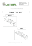
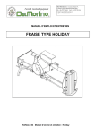
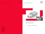
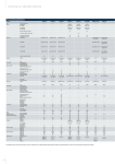
G43 - G44 GRINDING CYCLE.
The G43 function identifies the Grinding cycle with approaching of the piece from the left
side and introduction of the D tool radius.
Also in this case are valid the same consideration for G41.
The G44 function is equal to G43 excepted when the approach of the piece is from the
right side.
For the programming it is needed to replace G41 G42 with G43 "G44/n " and input the QZ
value, where:
/n = Number of cycles/minute ( Max. 999 )
Qz = Z deep excursion
Example:
N10 G0X0Y0Z0PA1M3S1000F150
N20 G43/300X10Y10QZ-4D3
N30 G1X18Y21
N10 G0X0Y0Z0PA1M3S1000F150
N20 G44/300X10Y10QZ-4D3
N30 G1X18Y21
The G40, G rapid, fixed cycle G, change tool G, G50, G60 functions erase the G43 or
G44.
C.B. Ferrari - Programming E560
PE560GB.DOC 20/05/04
425
CYCLES/MINUTE (/n)
650
600
550
500
450
400
350
300
250
200
150
100
50
1
2
3
4
5
6
7
8
9
10 11 12 13 14 15 16 17 18 19 20 21 22 23 24 25 26 27 28 29 30
35
40
45
DEEP EXCURSION IN Z (mm)
426
C.B. Ferrari - Programming E560
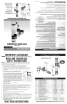
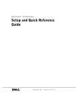
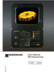
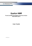
G45-G45/ PICK UP TOOL CYCLE.
It indicates the Pick up of Tool Automatic Cycle.
This function is used only if the Machine Tool has the Tools Magazine.
The tool machine can have two tools magazine, that could be equipped with guarding
(see Note 2).
By programming the G45/... (Increment high quota in mm ex. G45/50T1), the tool will
move higher, of the programmed value, from the normal mode.
The CNC will execute these operations in sequence:
1)
2)
3)
4)
5)
6)
7)
8)
Check for empty tool
Z rapid with Change of dimension assuming PA0 or PA9 origin (see Nota1).
Spindle and coolants stop and quill key positioning (see Notes 3-4)
Traverse on the XY position with co-ordinate of the requested Tool
Blow the air for the Cone cleaning
Traverse to Z0 plane with PAO (equivalent to the tool holder plane)
Release the electro valve for tool pick-up
Z rapid with Change of quote (This operation is automatically done after the tool
reset)
Example:
N10G45T1
N20G0X0Y0Z0PA1M3S1000F150
N30......................
C.B. Ferrari - Programming E560
PE560GB.DOC 20/05/04
427
5
8
2
140 (ISO 40)
180 (ISO 45/50)
140+T (ISO 40)
180+T (ISO 45/50)
11
428
C.B. Ferrari - Programming E560
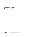
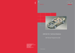
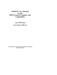
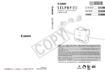
G47 TOOL RELEASE CYCLE.
It identifies the Automatic Release Tool Cycle.
Also in this case the considerations done for Cycle " G45 " are valid.
The CNC will execute these operations in sequence:
1)
2)
3)
4)
5)
6)
7)
8)
Z rapid with Change dimension assuming PA0 or PA9 origin
Spindle and coolants stop and key positioning
Traverse XY on Plane of co-ordinate of the selected tool
Traverse to Z0 with PAO (equivalent to the tool Holder Plane)
Electrovalve on and tool release
Check "Free Cone"
Z Rapid to the change quota
Electrovalve off
Example:
%N0
N10 G45T1
N20 G0X0Y0M3S1000F150PA1
N30 Z1
N40 G1Z-1
N50 X10Y10
N60 G0Z1
N70 G47
N80 G45T2
N90 G0X50Y50
N100........
C.B. Ferrari - Programming E560
PE560GB.DOC 20/05/04
429
140+T (ISO 40)
180+T (ISO 45/50)
3
4
1
140 (ISO 40)
180 (ISO 45/50)
430
7
C.B. Ferrari - Programming E560
IS O 4 0 /V 4 0
IS O 4 5 /V 4 5
IS O 5 0 /V 5 0
140
160
180
IS O 4 0 7 0
IS O 4 5 8 5
T O O L N °1 X 0 Y 0 Z 0
IS O 5 0 1 0 5
NOTES ABOUT G45 and G47:
1)
2)
3)
4)
5)
6)
7)
8)
9)
The G45 and G47 forced the absolute origin PA0 or PA9 dependently of the
programmed tool number. As it is possible to have two tools magazines, with equal
positions number, that number is defined in the Configuration file.
The first tools magazine must have the PA0 origin and the second the PA9 origin.
In the machine with two tools magazines it is obligatory that the one on the left have
the PA0 origin and the second one on the right the PA9 origin.
The G45 and G47 functions cancel eventual interpolation plane variation; the
G18 or G19 functions must be reprogrammed after the G45,or G47 functions.
The G45 and G47 functions cancel the origins translation G746 or G748
The G746 or G748 functions must be reprogrammed after the G45 or G47.
The G45 and G47 functions move the head in vertical position.
After tool change must be reprogrammed the head positioning if necessary.
The G45 and G47 functions cancel the radius compensation G41 G44.
After the G45 or G47 must be reprogrammed the functions that enable the
spindle rotation and the coolants.
During the execution of G45 or G47 the function M10 is forced.
If we break this cycles is necessary reprogrammed the functions M11{…..}.
Any functions programmed on the G47 line are ignored by the CNC, on the
G45 lines are accepted only the tool programming (T).
C.B. Ferrari - Programming E560
PE560GB.DOC 20/05/04
431
G49 [ ……. ] PROGRAM LINK.
It must be programmed before the final %.
Example:
N235G47
N236G49[\BLOCK\DDD]
N99999%
If a program, containing the G49 [program name], is charged on the CNC memory
(1PROG-LOAD) when the G49 function is executed the CNC automatically charge the
program indicated inside the parentheses and is executed immediately.
A few seconds passes between the end of the first program and the start of the second.
Call between different programs:
Example:
Program AA
%N0
...........
N99998 G49 [\BLOCK\BB]
N99999%
432
Program BB
"
#
"
Program CC
%N0
.............
N99998 G49 [\BLOCK\CC]
N99999%
" %N0
# ...........
"
............
N99999%
C.B. Ferrari - Programming E560
G50-G51 ROTOTRANSLATION.
The G50 function erases the G51.
The G51 function indicates a Rototranslation of the absolute reference system according
to a new Cartesian system of programmed co-ordinates in the same block.
One time the G51 function is activated, all the followings elements must be programmed
according to the new reference system. The translation and rotation values are programmed
in the line containing the G51 function:
G51X Y (translation) E (rotation angle)
Y+
Y+
X+
E
G51X..Y..E..
Y
PA1
X
X+
It is possible to program the rototranslation in routines by using the QX QY QE:
Example: N10.............
N20 G51 X0 Y0 E0
N30.............
N40.............
N50.............
N60 H1 N20 N50 QX10 QY10 QE30
The QX, QY, and QE values are reseted at the exit from the routines.
By using the G51 function it is impossible to rototranslate parts of programs with Q
incremental repetitions:
Example: %N0
N10 G51 X Y E
N20 G81 X Y Z R M S F PA1
N30 H5 N20 QX QY
Execute five G81 to the X Y quotes of the N20
N40 .............
line, for a correct program it is necessary to
refer the routine on the N30 line to the line
with the G51.
The G51 function execute first the translations and successively the rotations.
This function is active on the perpendicular plane of the tool either in G17 or G18 or G19
planes. The G51 remains activated since the CNC read the G50 function.
The G50 function is active at the CNC start.
It isn’t possible to use the function G51 together with G351, G751 or G752.
C.B. Ferrari - Programming E560
PE560GB.DOC 20/05/04
433
G55 HEAD ROTATION
It identifies the Rotation Cycle of the Head, without adjustment of the Work Plane to the
Rotation angle.
The G55 cancels the G56 G355 G356 G755 functions and the origin translation.
This function is modal, is active at the CN start and it is erased by the G55 G355 G356
G755
On machines series A B S the sign is positive for a clockwise rotation and negative for a
counter-clockwise rotation.
Example: %N0
.......
N10G55C-60
N20G0X50Y100Z50 PA1
The head is turned at -60 degrees.
Rotation point
Z+
PA..
434
Z+
X+
PA..
X+
C.B. Ferrari - Programming E560
G56 HEAD AND ORIGIN ROTATION
It identifies the rotation cycle of the head, with adjustment of the Work Plane to the
Rotation angle.
This function is modal and it is erased by the G55 G355 G356 G755 or by the RESET.
In the G56 block it is possible to program an origin translation in X, Y and Z.
This translation is calculated respect the original reference system before the rotation
head angle
The G56 function is allowed only in the X Y interpolation plane (G17).
No possible to use together G746 function.
Example: %N0
......
N10 G56 X-85 Y-10 Z-28 C-45
N11 G0 X0 Y30
N12 Z5
All the lines programmed after the N10 will be executed with an origin translation about 85mm in X, -10mm in Y, -28mm in Z and with the X Y plane rotated respect the Y axis since
be orthogonal to the head position (C45°).
With a axis C rotation of 90 degrees the axis X will move when it is programmed a Z axis
movement and vice versa.
The CNC visualize, on the screen, the quotes like if the head was always in the 0 angle
position.
Z+
Rotation point
PA..
PA..
X+
Z ..
Origin Translation
X ..
C.B. Ferrari - Programming E560
PE560GB.DOC 20/05/04
435
%N0
M10
M11{XYZ}
N1 G45T1
N2 G0X0Y0PA1
N3 G0Z2F300S3501M13
N4 G1Z-2
N5 G41X8Y2D5
N6 G3X0Y10I0J2
N7 G1X-10
N8 Y40
N9 X-30
N10 Y-40
N11 X30
N12 Y40
N13 X10
N14 Y10
N15 X0
N16 G3X-8Y2
N17 G40X0Y0
N18 G0Z10
N19 G0X60
N20 G56X50Y0Z-40C90
N21 H1N2N18
N22 G0X-50
N23 G56X0Y0Z0C0
N24 G0X-100
N25 P1=-(50+(55*COS15))
N25 P2=-55*SIN15
N26 G56XP1ZP2C-15
N27 H1N2N18
N28 G0Z20
N29 G56X0Y0Z0C0
N30 G47
N9999%
436
C.B. Ferrari - Programming E560
G58 ROTARY TABLE REVOLUTIONS RESET.
The G58 function is used for zero setting the revolutions counter of the absolute rotary
axis, defined with type 37 code in configuration.
Example:
%N0
N10 G0A840 that is 360°x 2 + 120°
N11 G58
Display A 120° or -240°
Without the G58 or M58 {axis name} the rotary axis can rotate from –20000 to 20000
degrees (end of travel limits).
The G58 function must be used for every PA.. origine definition in case of the rotary axis has
done many revolutions, this must be done at the beginning of the program or in MDI.
G59 RETURN FROM A MACRO.
The G59 function allows returning on the main program from a <Macro> cycle and must
be programmed at the end of this macro.
G60-G61 SCALE FACTOR.
The G60 function erases the G61.
The G61 function identifies the change of scale for the programmed axes, it is possible to
reduce or increase the real physic dimensions according to the programmed value.
Example: %N0
N10 G61 E1.5
N20 G0 X10 Y20 PA1
N30...........
increase factor (because >1)
moves to X15 Y30
The scale factor E is active only for X Y Z axes and modify this three axes at the same
time.
Besides it possible to define a different factor for each axis.
Example: G61X1.5Y2Z3 or G61A-1
Y+
G61E>1
G61E<1
X+
C.B. Ferrari - Programming E560
PE560GB.DOC 20/05/04
437
G63 HIGH SPEED MILLING OF PROFILES AND SURFACES (OPTIONAL)
The new G63 has been realised to perform the finishing and the time of execution.
The result is a smooth and continuous movement of the machine even with high cutting
speed. The mains innovations are:
1) The ISO program trajectory (points “G1” and/or circles “G2-G3”) is processed internally
and the result is a tool path with high degree of continuity (till the Jerk).
2) The geometrical interpolation soft the tangency and curvature discontinuity generated by
the CAM.
3) Are introduced new algorithms for the management of angular points that the NC deletes if
on the programmed tolerance.
It is necessary to weigh up the use of the operator for the tolerance parameter E on the G63
function:
N10 G63 E0.02
In the previously G63 release (as in RIPUNTI, program on the NC to convert in Spline
“G360”) the tolerance parameter can be express in hundreds of millimetre or tenths of
millimetre during roughing or half-finishing execution: in those working phases when is
presents a machining allowance of tenth or hundreds of millimetre.
In finishing, instead, the E parameter must not be bigger than few microns (from 1 to 3).
438
C.B. Ferrari - Programming E560
In the new G63 release the tolerance parameter has a meaning deeply different and takes
the concept of “maximal local deformation where it is possible to manage the desired degree
of continuity”.
The tolerance parameter can and must be of some hundreds to guarantee on the finishing
surface the disappearance of the “point-point” effect, without to compromise the quality of the
finishing.
If the operator programs a tolerance of few microns the G63 reproduces exactly all the
particulars of the original geometry.
These are the rules for the use of the E parameter:
FINISHING
Processing Typology
Tolerance Parameter E (mm.)
Blended Surfaces with more degrees of continuity
CAM with tolerance of few microns that produces
contiguous linear elements that forms angles in order
on one degree (or less).
Blended Surfaces in tangency
CAM with tolerance in order of one hundred of mm.
that produces contiguous linear elements that forms
angles of some degrees.
CAM not particularly precise that produces
contiguous linear elements that forms significant
angles and of irregular entity.
E<0.02
0.02<E<0.03
0.03<E<0.05
ROUGHING OR HALF-FINISHING
Machining Allowance
0.060
0.075
0.090
0.120
0.150
0.180
0.210
0.300
0.400
0.500
0.600
0.700
Tolerance Parameter E (mm.)
0.050
0.055
0.060
0.070
0.080
0.090
0.100
0.180
0.220
0.260
0.300
0.340
In a bloc G63 without parameter E is assigned a default value E0.005
With a value E equal or Greater of 0.005 the movement is more soft but we can found
arounded edges.
In case of surfaces with edges to respect to program E values lower then 0.005.
C.B. Ferrari - Programming E560
PE560GB.DOC 20/05/04
439
G70 G71 INCH-METRIC MODES.
RUNNING IN "WINDOWS NT" :
The visualisation can be modified with the appropriate menu (show), for necessity, in mm. or
inches. (But don’t modify the execution)
A change, out of respect for the value of the PLC entire constant K18, is NOT memorized.
The condition of the PLC integer constant K18, determines the CNC start mode of
visualisation and running: if 0 in mm., if 1 in inches.
By programming the G70 function it is possible to use programs in inch dimensions.
By programming the G71 function return to use programs with metric dimensions.
G70 and G71 are independent of the operating mode set by the value of K18.
The G70 functions affect linear axes co-ordinates, cycles, D and F values.
_________________________________________________________________________
To use the P Parameter with the value in inch it is necessary to write in the block after the
value the item i.
Example : P10=3.78i
440
( same as P10=96.012 )
C.B. Ferrari - Programming E560
G80 DRILLING CYCLE RESET.
The G80 function cancels any drilling cycle (from G81 to G89).
G81 - G81/ DRILLING CYCLE.
It identifies the Drilling or Blading cycle with or without High Return.
Example: %N0
N1 G0 X Y Z A B PA. T..
N2 G81/.. X Y Z A B L R QZ- M.. S.... F.....z.....f.....
The CNC will execute these operations in sequence:
1) Traverse to position X Y A B
2) Traverse to L Plane
2a)Feedrate f to (L+z)
3) Feedrate F to programmed Z plane (with stops)
4) Stops at the bottom.
5) Return at traverse to R plane with spindle on.
Programming G81/ has a stop at the bottom, for a number of revolutions equal to the
input value after the slash.
By programming QZ this stops is executed for all the time that the perpendicular axis does
the QZ.. incremental move.
If is programmed the QZ value without the / after the G81, the plane perpendicular axis
stops and immediately restart.
THE QZ VALUE MUST BE ALWAYS NEGATIVE.
After programming a G81-89 or a G96-97 function, the CNC forgets the previous
programmed L value but considers the one defined in the G.. block of the fixed cycle used..
In case that, IN THE FIXED CYCLE DEFINITION BLOCK, the L dimension is omitted, the
position is done on R dimension. If both R and L values are omitted the CNC considers the
last programmed R-value. If this doesn't exist the traverse and the return to the plane
perpendicular axis will be executed to the zero quote.
For execute a series of drilling cycle it is not necessary to rewrite the address G but, in the
followed blocks, the new co-ordinates and if changed the others informations about: F, S, R,
L, Z.
If ‘z’ or ‘f’ = 0 the point 2a) is not executed. The passage between the point 2a and the point
3 is executed without stop. The point 3 is always executed by feedrate (F).
G82 DRILLING CYCLE.
IDENTICAL AT THE G81 FUNCTION
G81 G82
C.B. Ferrari - Programming E560
PE560GB.DOC 20/05/04
441
e.g.
G81X..Y..Z-..R..
G0
X..Y..
G1
L(R)
R
Z-
e.g.
G81/..X..Y..Z-..R..QZ-..
G0
X..Y..
G1
R
L(R)
PAUSE
QZZ-
442
C.B. Ferrari - Programming E560
G83 DEEP DRILLING CYCLE.
It identifies the Deep Hole Drilling Cycle
Example: %N0
N1 G0 X Y Z A B PA. T..
N2 G83 X Y Z A B L R QZ- M.. S.... F..... z..... f..... r…
The CNC will execute these operations in sequence:
1) Traverse to X Y A B position.
2) Traverse to L.
2a)Feedrate f to (L+z)
3) Feedrate F to L+QZ.
4) Traverse return to the L.
5) Traverse to L+QZ.
6) Feedrate to L+QZ + (QZ-10%).
7) Repeat the described operations in point 4, decrementing the QZ till a
max. up to 50% and reach the Z final dimension.
8) Traverse to the R plane with the Spindle on.
THE QZ VALUE MUST BE ALWAYS NEGATIVE.
After programming a G81-89 or a G96-97 function, the CNC forgets the previous
programmed L value but considers the one defined in the block with G.. of the fixed cycle
used.
In case that, IN THE FIXED CYCLE DEFINITION BLOCK, the L dimension is omitted, the
position is done on R dimension. If both R and L values are omitted the CNC considers the
last programmed R-value.
If this doesn't exist the traverse and the return to the plane perpendicular axis will be
executed to the zero quote.
For execute a series of drilling cycle it is not necessary to rewrite the address G but, in the
followed blocks, the new co-ordinates and if changed the others informations about: F, S, R,
L, Z.
It is possible to program the r.. parameter that permit to return on the hole in rapid by
stopping r… millimeters higher than the quotas reached previously (if not programmed r =
1/10 of QZ.…).
C.B. Ferrari - Programming E560
PE560GB.DOC 20/05/04
443
G84 TAPPING CYCLE.
It identifies the Tapping cycle.
Example: N1 G0 X Y Z A B PA. T..
N2 G84 X Y Z A B R M.. S.... F.....QZ.....
The CNC will executed these operation in sequence:
1) Traverse to the X Y A B position.
2) Traverse to the L plane.
3) Feedrate to the Z plane.
3a) Executed in substitution of point 3 if programmed the:
Feedrate to L+QZ or to L+QZ + (QZ - 10%)
4) Spindle motion reverse and return at feedrate to the R plane.
5) Remove spindle reversal.
6) Traverse to the R plane.
It continue to repeat the operations defined in the points 3a 4 and 5 decrementing the QZ of
the 10% each time until to a maximum of the 50%. Reach this value the QZ stays constant
up to the attainment of the final quota.
In G84 cycle the value of the started F has the Drilling pitch and it is express in
Micron/Revolutions (F 1000 = 1 mm./rev.).
The axis in operation goes on following the programmed pitch with the number of the
spindle revolutions, so we also modify the revolutions with the Override Spindle
potentiometer, the Drilling does not feel the effects.
The M3/M4 function decides whether right or left spindle rotation.
After programming a G81-89 or a G96-97 function, the CNC forgets the previous
programmed L value but considers the one defined in the G.. block of the fixed cycle used.
In case that, IN THE FIXED CYCLE DEFINITION BLOCK, the L dimension is omitted, the
position is done on R dimension. If both R and L values are omitted the CNC considers the
last programmed R-value. If this doesn't exist the traverse and the return to the plane
perpendicular axis will be executed to the zero quote.
For execute a series of drilling cycle it is not necessary to rewrite the address G but, in the
followed blocks, the new co-ordinates and if changed the others informations about: F, S, R,
L, Z.
444
C.B. Ferrari - Programming E560
G83
E.g.
G83X..Y..Z-..R..QZ-..
G0
X..Y..
G1
R
L(R)
QZQZ-10%
Z-
G84
E.g.
G84X..Y..Z-..R..F..
G0
X..Y..
L(R)
Z-
C.B. Ferrari - Programming E560
G1
R
ORIGINAL SPINDLE
DIRECTION RESTART
SPINDLE ROTATION
REVERSAL
PE560GB.DOC 20/05/04
445
G85 DEEP HOLE DRILLING CYCLE.
It identifies the Deep Hole Drilling Cycle
Example: %N0
N1 G0 X Y Z A B PA. T..
N2 G85 X Y Z A B L R QZ- M.. S.... F.....z....f....
The CNC will execute these operations in sequence:
1) Traverse to X Y A B position
2) Traverse to L
2a) Feedrate f to (L+z)
3) Feedrate F to L+QZ
4) Traverse return to the R plane
5) Traverse to L+QZ
6) Feedrate to L+QZ + (QZ-10%)
7) Repeat the described operations in point 4, decrementing the QZ till a
max. up to 50% and reach the Z final dimension
8) Traverse to the R plane with the Spindle on
THE QZ VALUE MUST BE ALWAYS NEGATIVE.
After programming a G81-89 or a G96-97 function, the CNC forgets the previous
programmed L value but considers the one defined in the block with G.. of the fixed cycle
used..
In case that, IN THE FIXED CYCLE DEFINITION BLOCK, the L dimension is omitted, the
position is done on R dimension. If both R and L values are omitted the CNC considers the
last programmed R-value. If this doesn't exist the traverse and the return to the plane
perpendicular axis will be executed to the zero quote.
To execute a series of drilling cycle it is not necessary to rewrite the address G but, in the
followed blocks, the new co-ordinates and if changed the others informations about: F, S, R,
L, and Z.
446
C.B. Ferrari - Programming E560
G86 BORING CYCLE
It identifies the Boring Cycle.
Example:
%N0
N1 G0 X Y Z A B PA. T..
N2 G86/ X Y Z A B R L M.. S.... F.....
The CNC will execute these operations in sequence:
1) Traverse to position X Y A B
2) Traverse to L Plane
3) Feedrate to programmed Z plane
4) Stops at the bottom (by programming G86/)
5) Spindle stops and return at traverse to R plane
6) Spindle rotation on
Programming G86/ has a stop at the bottom, for a number of revolutions equal to the
input value after the slash.
By programming QZ this stops is executed for all the time that the perpendicular axis does
the QZ.. incremental move.
If is programmed the QZ value without the / after the G81, the plane perpendicular axis
stops and immediately restart.
THE QZ VALUE MUST BE ALWAYS NEGATIVE.
After programming a G81-89 or a G96-97 function, the CNC forgets the previous
programmed L value but considers the one defined in the block with G.. of the fixed cycle
used.
In case that, IN THE FIXED CYCLE DEFINITION BLOCK, the L dimension is omitted, the
position is done on R dimension. If both R and L values are omitted the CNC considers the
last programmed R-value. If this doesn't exist the traverse and the return to the plane
perpendicular axis will be executed to the zero quote.
To execute a series of drilling cycle it is not necessary to rewrite the address G but, in the
followed blocks, the new co-ordinates and if changed the others informations about: F, S, R,
L, and Z.
G87 BORING CYCLE
IDENTICAL AT THE G86 FUNCTION
C.B. Ferrari - Programming E560
PE560GB.DOC 20/05/04
447
G85
E.g.
G85X..Y..Z-..R..L..QZ-..
G0
X..Y..
G1
R
L
QZ-
QZ-10%
Z-
G86 G87
E.g.
G86X..Y..Z-..R..
G0
X..Y..
L(R)
Z-
448
G1
R
SPINDLE ROTATION
RESTART
STOP SPINDLE
ROTATION
C.B. Ferrari - Programming E560
G88 DRILLING CYCLE FOR SPACED WALLS
It identifies the Drilling Cycle for Spaced Walls
Example : %N0
N1 G0X Y Z A B PA. T..
N2 G88/ X Y Z A B R z f
N3 Z' R'
N4 Z" R"
N5 G0Z
N6 .........
The CNC will execute these operations in sequence:
1) Traverse to X Y A B in the plane.
2) Traverse to the R plane.
2a) Feedrate f to (L+z)
3) Feedrate F up to the Z plane.
4) Eventual stop if G88/ is programmed N3 block:
5) Traverse to the R' plane.
5a) Feedrate f to (L+z)
6) Feedrate F to the Z' plane N4 block:
7) Traverse to the R" plane.
7a) Feedrate f to (L+z)
8) Feedrate F to the L" plane.
In the N3 and N4 blocks are programmed only the Z and R-values.
By programming G88/ the machine has a stop at the final feedrate quote, for a number of
revolutions equal to the input value after the slash, and after executed the successive block.
To exit from the piece it is necessary to program an exit block.
After programming a G81-89 or a G96-97 function, the CNC forgets the previous
programmed L value but considers the one defined in the block with G.. of the fixed cycle
used..
In case that, IN THE FIXED CYCLE DEFINITION BLOCK, the L dimension is omitted, the
position is done on R dimension. If both R and L values are omitted the CNC considers the
last programmed R-value. If this doesn't exist the traverse and the return to the plane
perpendicular axis will be executed to the zero quote.
For execute a series of drilling cycle it is not necessary to rewrite the address G but, in the
followed blocks, the new co-ordinates and if changed the others informations about: F, S, R,
L, Z.
C.B. Ferrari - Programming E560
PE560GB.DOC 20/05/04
449
G89 REVERSE BORING CYCLE
It identifies the Reverse Boring Cycle
Example: %N0
N1 G0 X Y Z A B PA. T..
N2 G89/ X Y A B Z- R L M.. S.... F.....
The CNC will execute these operations in sequence:
1) Traverse to position X Y A B.
2) Traverse to the L Plane.
3) Feedrate to programmed Z plane.
4) Stops if programmed G896/.
5) Feedrate to the L plane.
6) Traverse to the R plane.
By programming G88/ the machine has a stop at the final feedrate quote, for a number of
revolutions equal to the input value after the slash, and after traverse to the R plane.
After programming a G81-89 or a G96-97 function, the CN forgets the previous
programmed L value but considers the one defined in the block with G.. of the fixed cycle
used.
In case that, IN THE FIXED CYCLE DEFINITION BLOCK, the L dimension is omitted, the
position is done on R dimension. If both R and L values are omitted the CN considers the last
programmed R-value. If this doesn't exist the traverse and the return to the plane
perpendicular axis will be executed to the zero quote.
To execute a series of drilling cycle it is not necessary to rewrite the address G but, in the
followed blocks, the new co-ordinates and if changed the others informations about: F, S, R,
L, and Z.
450
C.B. Ferrari - Programming E560
G88
E.g.
G88X..Y..Z-..R..
Z'-..R'-..
Z''-..R''-..
G0Z2
G0
X..Y..
G1
R
ZR'-
Z'R''-
Z''-
G89
E.g.
G89X..Y..Z-..R..
G0
X..Y..
L(R)
G1
R
Z-
C.B. Ferrari - Programming E560
PE560GB.DOC 20/05/04
451
G94 FEEDRATE IN mm/min
The G94 function identifies the Tool Machine feedrate in mm/min. that is the natural way
that the Numerical Control has still from the beginning.
G95 FEEDRATE IN micron/rev
The G95 function identifies the Tool Machine feedrate in micron/revolutions, that can be
useful in borings.
452
C.B. Ferrari - Programming E560
G96 BORING CYCLE
This instruction identifies the macroinstruction for boring with detachment from the wall.
Example: N10 GO X Y Z A B PA. T..
N20 G96/ X Y Z A B E R L M.. S.... F.....
The E function is the spindle key angle respect the X+ axis.
It is POSITIVE the angle that the quill key has to execute, in counter clockwise way,
starting from the X+ axis; NEGATIVE, the angle executed in clockwise way.
By mounting the tool with the same orientation of the spindle key at the end of the cycle
the tool will executes a detachment from the wall and after will traverse to the R plane.
The CN will execute these operations in the following sequence:
1)
2)
3)
4)
5)
6)
Traverse to X Y A B position
Traverse to L
Feedrate to the Z plane
Stops if programmed G96/
Spindle stops and spindle key positioning
Moving the X Y axes about 2 tenths of millimetre in direction defined with
the E angle value.
7) Traverse to the R plane
8) Traverse to the number 1) X Y plane.
9) Spindle rotation on.
By programming G96/ the machine has a stop at the final feedrate quote, for a number of
revolutions equal to the input value after the slash, and after traverse to the R plane.
After programming a G81-89 or a G96-97 function, the CN forgets the previous
programmed L value but considers the one defined in the block with G.. of the fixed cycle
used..
In case that, IN THE FIXED CYCLE DEFINITION BLOCK, the L dimension is omitted, the
position is done on R dimension. If both R and L values are omitted the CN considers the last
programmed R-value. If this doesn't exist the traverse and the return to the plane
perpendicular axis will be executed to the zero quote.
The E angle must be always equal of the spindle key angle and also the tool. For the
Machine equipped with automatic tool change or with a Multiplexed rotary head this angle is
225 degrees.
In the others cases this angle must be measured.
If the E angle is omitted the CN take the ZERO value.
To execute a series of fixed cycle it is not necessary to rewrite the address G but, in the
followed blocks, the new co-ordinates and if changed the others informations about: F, S, R,
L, and Z.
C.B. Ferrari - Programming E560
PE560GB.DOC 20/05/04
453
G96
E..
0,2
Example of boring cycle:
%N0
N1 G45T1
N2 G96 X0 Y0 Z-20 R2 E30 F400S2000M13PA1
N3 X100
N4 G47
N9999%
454
C.B. Ferrari - Programming E560
G97 MILLING A BORE AND MILLING A THREAD CYCLES
This instruction identifies the macroinstruction for two operations: Milling a Bore and also
milling a Thread.
The CN recognizes the one from the other function by verifying the existence of the QX
parameter in the G97 block:
- If in the G97 block is programmed a QX different from zero or if the previous QX has
not be deleted by programming the QX0, the CN will recognize the Milling a Bore cycle.
- If in the block is programmed a QX= or if don't exist previous QX, the CN will recognize
the Milling a Thread cycle.
Milling a Bore cycle
example :
N10 G0 X Y Z A B PA. T..
N20 G97 X Y Z A B R L QZ QX D M.. S
F
Where:
QZ = Distance raised from the bottom.
QX = Radius of the outer Bore.
D = Tool Radius.
The CNC will execute these operations in the following sequence...
1)
2)
3)
4)
5)
Traverse to X Y A B position.
Traverse to L.
Feedrate to the Z plane.
Reverse traverse to Z + QZ position.
a) In a case when QX < D, the machine will 'Cut-Out' and error 13 will appear.
b) In a case when QX < 2D, it will join the radius at (QX-D)/2
c) In a case when QX > 2D, it will execute a linear approach to a point X+
(QX-D) and then execute a radius with the value (QX-D)/2.
6) Clockwise circular interpolation with a centre X Y and with radius QX-D
7) Detachment from the workpiece with a radius (QX-D)/2 and return to the point X
Y in linear interpolation.
8) Traverse to R plane.
C.B. Ferrari - Programming E560
PE560GB.DOC 20/05/04
455
G97 Milling a Bore
Example of milling a bore:
%N0
N1 G45T1
N2 G97 X60 Y0 Z-23 L2 R10 QX42.5 D10 F400S2000M13PA1
N3 X-60
N4 G47
N9999%
456
C.B. Ferrari - Programming E560
Milling a Thread cycle
Example:
N10 G0 X Y Z A B PA. T..
N20 G97 X Y Z A B R L QZ E K W M.. S... F....
Where:
QZ+- =Distance raised from the bottom.
E +- = Radius path of centre tool. The sign indicates the thread direction:
+ = Counter clockwise, - = Clockwise.
K +- = Pitch of thread.
W +- = Pitch of helical approach to the workpiece.
The CNC will execute these operations in the following sequence:
1)
2)
3)
4)
5)
Traverse to the X Y position
Traverse to L
Feedrate to the Z plane
Reverse traverse to Z + QZ plane.
Approach to the workpiece with helical interpolation of radius E/2 and
Pitch W, to the point X+E. The start position of the thread in Z-axis is then
Z+QZ+W/2.
6) Helical interpolation, Clockwise (E+) or Counter clockwise (E-) with centre X
Y, radius E, and pitch K.
7) Detachment from the workpiece with helical interpolation radius E/2 and pitch
W to the point X+E.
8) Return to the R plane
After programming a G81-89 or a G96-97 function, the CN forgets the previous
programmed L value but considers the one defined in the G block of the fixed cycle used.
In case that, IN THE FIXED CYCLE DEFINITION BLOCK, the L dimension is omitted, the
position is done on R dimension. If both R and L values are omitted the CN considers the last
programmed R-value.
If this doesn't exist the traverse and the return to the plane perpendicular axis will be
executed to the zero quote.
If activated the G341 function the D value is ignored and the CN consider the radius value
imposed in the detailed table.
For execute a series of fixed cycle it is not necessary to rewrite the address G but, in the
followed blocks, the new co-ordinates and if changed the others informations about: F, S, R,
L, Z.
C.B. Ferrari - Programming E560
PE560GB.DOC 20/05/04
457
G97 Milling a Thread
Example of milling a thread:
%N0
N1 G45T1
N2 G99 P1=13.5-(21.1/2)
N3 G97X-100 Y0 Z-21 R2 QZ0 EP1 K3 W1.5 F400S2000M13PA1
N4 X100
N5 G47
N9999%
458
C.B. Ferrari - Programming E560
G99 AXES STOP
It is used for input M functions or messages.
This function delete the previously G function.
Don’t insert this function inside a contouring.
For Manual Tool Change, with the " M6 T "
Example : %N0
N10 G99M6T1
C.B. Ferrari - Programming E560
PE560GB.DOC 20/05/04
459
Example ISO programming
460
C.B. Ferrari - Programming E560
%N0
N1
N2
N3
N4
N5
N6
N7
N8
N9
N10
N11
N12
N13
N14
N15
N16
N17
N18
N19
N20
N21
N22
N23
N24
N25
N26
N27
N28
N29
N30
N31
N32
N33
N34
N35
N36
N37
N38
N39
N40
N41
N42
N43
N44
N45
N46
N47
N48
N49
N50
G99 (TSPP_E500)
G45T1 (ROUGH-MILL D. 18)
G99 (TSPP_E500, DIAM18)
F266S1125PA1
G0X70Y0
M13
G0Z2
G1Z-2.5
G41X60Y-20D9.5
G1Y-40
G3X70Y-50I70J-40
G1X80
G3X90Y-40I80J-40
G1Y-20
X100
G3X125Y-45I125J-20
G1Y-90
G2X100Y-115I100J-90
G1X50
G2X25Y-90I50J-90
G1Y-45
G3X50Y-20I25J-20
G1X60
H1N8N23QZ-2.5
G0Z2
G0X75Y-82.5
G1Z-2.5
G41X75Y-105D9.5
G1X96.236
G3X104.896Y-100I96.236J-95
G1X112.113Y-87.5
G3Y-77.5I103.453J-82.5
G1X104.896Y-65
G3X96.236Y-60I96.236J-70
G1X53.764
G3X45.104Y-65I53.764J-70
G1X37.887Y-77.5
G3Y-87.5I46.547J-82.5
G1X45.104Y-100
G3X53.764Y-105I53.764J-95
G1X75
H1N27N41QZ-2.5
G47
G45T2( FINISH-MILL D. 18)
G99(TSPP_E500, DIAM18)
F230S1200PA1
H1N5N42QD-.5
G47
G45T3( CENTER-DRILL D. 10)
G99 (TSPP_E500, DIAM10)
C.B. Ferrari - Programming E560
N51 F128S787PA1
N52 G0X90Y-82.5
N53 G81Z-6.5R-3M13
N54 X75Y-67.5
N55 X60Y-82.5
N56 X75Y-97.5
N57 G47
N58 G45T4( TWIST-DRILL D.6.75)
N59 G99(TSPP_E500, DIAM6.75)
N60 F185S1414PA1
N61 G0X90Y-82.5
N62 G83Z-21.528R-3QZ-6.75M13
N63 X75Y-67.5
N64 X60Y-82.5
N65 X75Y-97.5
N66 G47
N67 G45T5( SCREW-TAP ISO D. 8)
N68 G99 (TSPP_E500, DIAM8)
N69 F1250S258PA1
N70 G0X90Y-82.5
N71 G84Z-18R-3L2M13
N72 X75Y-67.5
N73 X60Y-82.5
N74 X75Y-97.5
N75 G47
N9999%
PE560GB.DOC 20/05/04
461
Gxxx MACRO (Subroutine)
A Macro (Subroutine) is an ISO part-program that must start WITHOUT the character '%' and
must FINISH with the function G59 (The main program start and finish with the character
'%').
The Macro is called with the Gnumber function from the main program or from another
subroutine. (The number can goes till 999; but the user must use from 101 to 299).
When the number is the same as a CNC existing function this replace the old G function.
The Gnumber function gives the name to the file that must be charged in the directory
C:\MACRO.
The Gnumber function must be write on the list of the file GIUTEN.CNC in the directory
C:\MACRO.
Part-Program
(FILE AAA)
%N0
N1
N2 Gxxx------->
N3
<-N4
|
N5
|
N6000%
|
|
<--
(FILE Gxxx)
N10
N20
N30 Gyyy ------>
N40
<-N50
|
N60
|
N70 G59
|
<--
(FILE Gyyy)
N100
N200
N300
N400 Gzzz ------->
N500
<-N600 G59
|
|
<--
(FILE Gzzz)
N1000
N2000
N3000
N4000
N5000 G59
On the macros the programming rules are the same as the rules on the main part-program.
The CNC dispose of a memory about 256 Kbytes for the macro.
A routine H must have start and end in the same file.
The routine levels are accumulated for each macro.
On the main part-program it is possible to write only the parameters from P0 to P99, on the
macros only from P100 to P199.
The main program and the macros can read all the parameters.
462
C.B. Ferrari - Programming E560
Program with call of a macro:
Main Program
%N0
N1 G45T1
N2 G99 PA1 F3000 S500 M13
P1=0
P2=0
P3=15
P4=20
P5=12
P6=10
P7=-2.5
P8=15
P9=1
N3 G197
N4 G47
N99999%
Macro G197
N197001 G99(MACRO FOR MILLING AN EXTERNAL THREAD)
(
P1= Centre in X
(
P2= Centre in Y
(
P3= Inside diameter
(
P4= Outside diameter
(
P5= Safety Z
(
P6= Final Z
(
P7= Step +/(
P8= Tool Radius
(
P9= Number of helix
N197002 P100=P3/2
N197003 P101=P4/2
N197004 P102=P101-P100+P8+1
N197005 P103=P100+P102
N197006 P104=P100/P102
N197007 P105= - P102
N197008 P107=P7/P104
N197009 P108=P107/4
N197010 P109=P9
N197011 P106=P6-P108-P7
N197012 G51XP1YP2
N197013 G0XP103Y0
N197014 ZP5
N197015 G1ZP106
N197016 G41XP103YP102DP8
N197017 G3XP100Y0IP103J0KP107
N197018 G2I0J0KP7
N197019 P109=P109-1
N197020 P109>0 N197018
N197021 G3XP103YP105IP103J0KP107
N197022 G40Y0
N197023 G0ZP5
N197024 G59
C.B. Ferrari - Programming E560
PE560GB.DOC 20/05/04
463
FUNCTIONS FOR TOOLS PRESETTING
TOOL LENGTH AND TOOL RADIUS SETTING PROCEDURE
Zero setting device instrument positioning.
This instrument must be mounted in a Tool Machine X, Y and Z accessible axes position.
The head of this instrument is used to set and to verify the tools lengths; the other head in
the lateral position is used to set and to verify the tools diameters.
The position of this instrument must be indicated on SHIFT-F9 (see the following picture):
the X, Y quotes are referred to the centre of the zero setting head, while the Z quote is
positioned near this one (~2 mm over).
To zero setting this instrument (during the installation or if this instrument has been
moved) it is necessary to move to the centre in X Y and in Z ~2 mm between the spindle key
and the head for the length zero setting and:
Find the length key centre
Y+
X+
Press SHIFT+F9 (OFFSET)
Press F4 (AZZER)
By using #$ select QUOTE INPUT X axis
Press ENTER
Press ENTER
By using " select QUOTE INPUT Y axis
Press ENTER
Press ENTER
Set the Master-tool ~ 2 mm over the length key
Z+
By using " select QUOTE INPUT Z axis
Press ENTER
Press ENTER
Press F12 to exit
2 mm
X+
464
C.B. Ferrari - Programming E560
Measure cycle and tool verify description:
These cycles are realized in special subprogram that can be recalled in the part-program
by using some "G" functions:
G300
- Tool length measure with table adjournment.
G301
- Tool length verify with programmed stops (M1) if the verified tool
length is out of tolerance.
G302
- Tool length verify with automatical research of the tool with equal class
(if different from 0) when the verified tool length is out of tolerance.
If the tool length is on tolerance the CN adjourn the table.
G303
- Tool radius measure with table adjournment.
G304
- Tool radius verify with programmed stop (M1) if the verified tool
radius is out of tolerance.
G305
- Tool radius verify with automatical research of the tool with equal
class (if different from 0) when verified tool radius is out of tolerance.
If the tool radius is on tolerance the CN adjourn the table.
G306
- Tool length and radius measure with table adjournment.
All cycles have the acquisition of sample quotas to measure and verify the tools.
For the tool lengths the sample quota is done on the spindle key.
For the tool radius the sample quota is done with the sample tool (T 16) that have the
radius dimension write in configuration (K 17 constant in micron). Each measure of length
and radius is done two times consequently; the tolerance between the two measures is
written in configuration (K 15 float constant).
With the K16 float constant the tool-holder cone to zero setting the spindle key is defined
and is expressed in millimetres.
The tolerance to verify the tools is written in the calling subprogram part program after "/"
character and is expressed in millimetres with the point "." to separate integers from
decimals.
It is usable with all verify cycles. When "/" character is not programmed or when its value
is zero, the verify cycle become a normal measure cycle.
The qualification of this instrument is done with these functions:
G377
G378
Setting of the instrument for the tools length.
Move the machine manually with the special tool over the instrument for
the tools length and write G377F1000.
Setting of the instrument for the tools radius.
Move the machine manually with the special tool near the instrument for
the tools radius and write G378F1000.
C.B. Ferrari - Programming E560
PE560GB.DOC 20/05/04
465
- Tool table disposition for the automatical tool managing:
Cls
- number from 0 to 255 to indicate the same tools in the holder plate.
When this number is = 0 tools are managed in the traditional way and any
automatical tool research is allowed.
When this number is different from 0 this means:
same numbers = same tools type.
This makes the automatical substitution of a non-usable tool to another with
the same number.
@
- Defines the tool work rotation way:
If - the work rotation way is clockwise, if + counter clockwise.
L
- Tool length: can be edited or the value obtained by the automatical
zero setting is keeped.
DL
- Delta of the tool length: can be edited and its value is summed to the l value.
Every time the tool is automatically measured this value became 0.
r
- The same meaning like l for the tool radius.
Dr
- The same meaning like Dl for the tool radius.
ts
ts
- Tool lifetime in seconds
- Processing number decrease by the M387 function, if the N bit of status is
active
status
- Tool status informations:
L Is written for all the times the tool length measure is done using the
automatical cycle.
D Is written for all the times the tool radius measure is done using the
automatical cycle.
T Tool Life time. With ts and cl activate the check of tool lifetime.
N If programmed, alternative with the T, takes the Ts value as a pure number.
X Non usable tool: is written for all the times the tool has not passed the verified
cycle (length or radius) and the tool became non-usable, if the cl value is
different from zero the automatical search is enabled.
All this values are editable also from the keyboard.
466
C.B. Ferrari - Programming E560
TOOL LIFETIME MANAGEMENT
This check is activated only when in the tools table the CL is different from 0 and it is present
the bit " T " on the STATUS.
In the table this values can be written in different ways:
a) By editing the table in manual and writing the time in minutes.
b) In the block that call a tool measure function ( G300, G303, G306 ) writing the letter " t" (
small ti ) with the lifetime in minutes.
c) The tool dimensions can be transferred from the part-program to the table in a block as
the following:
N100 G99 M300 M364 {T12C10L100Dl0.5R7DR0.05t8500(-LDT)"Tool Description"}
The values written in the parenthesis { } except what is inside the " ", are transferred in the
tools table. Each tool has the same form as the .UTI files generated after a tools table save:
T - Tool number: whole number from 1 to 199.
C - Tool classes: whole number from 0 to 99.
L - Tool length: in mm with the point that separate the decimals.
DL - Tool Delta Length: in mm with the point that separate the decimals.
R - Tool radius: in mm with the point that separate the decimals.
DR - Tool Delta Radius: in mm with the point that separate the decimals.
t
- Tool work time: in seconds from 0 to 99999.
(-LDT) Where:if - tool work clockwise, if + counter clockwise.
LD flag of the tool status.
T if present active the check of the tool lifetime.
" " - Tool description max. 20 characters.
It is not necessary to write all this parameters but only the ones that you need.
The M300 function write in the bloc is used to adjourn the tools file.
The tool working time is kept in a partial counter that is adjourned all the time that the tool is
working and simultaneously is verified that the tool working time is not bigger than the one
inserted on the table.
When the tool finishes the established work time it is replaced with a tool with the same class
then continue the execution. In the table the substituted tool will have the bit " X " and its
work time is annulled.
The execution restart with an automatic repositioning that with the following order:
1) Spindle rotation restart.
2) Tilting head repositioning.
3) X and Y-axes repositioning.
4) Z axis repositioning.
When the tool is substituted before to have finish its work time the table is adjourned with the
remaining time.
The table is adjourned with the worked time also if the CNC is resetted by pushing <Shift F11> without to have release the tool in the magazine.
If the CNC is switching off without the reset procedure the remaining tool time is NOT
adjourned on the table.
C.B. Ferrari - Programming E560
PE560GB.DOC 20/05/04
467
This group of M functions permits the management from a program of the tool substitution
that has finished its lifetime.
If this mode is active the tool substitution is executed only from the program
In this way we avoid the milling interruptions with the tool in contact with the piece or during
the phases of milling where it is not advisable to substitute the tool.
This function must be programmed at the end of positioning (G0 rapid movements) or in lines
of G99.
The tool lifetime is activated on the machine for all the tools on the cone and that have the
followings parameters on the tools table:
a)
b)
c)
d)
A value different from 0 defined under the voice ‘cl’ (class).
The parameter ‘T’ (time) under the voice ‘status’.
A time value (in seconds) different from 0 under the voice ‘τs’.
The parameter ‘X’ under the voice ‘status’ means that the tool is useless.
If a processing doesn’t finish its defined lifetime the table is adjourned with the residual value
every time the tools is released on the tools magazine.
The M1316 function active the programmed substitution mode.
The M1315 function (default condition) cancels the programmed substitution mode.
The M1317 function executes immediately the substitution of the tool only if its lifetime is
finished.
The function M1317 is ignored if the tool lifetime on the cone is not finished.
The function M1317 is ignored when the tool with the lifetime finished is release from the
cone with a function (G47, M06).
E.g.:
%N0
N10 G99 M1316
N30
N40 G349[prg1]
N50 G349[prg2]
N60 G349[prg3]
N70 G349[prg4]
N80 G99
N9999%
[prg1] %N0
N10 G45T1
…..
N1000 G47
N9999%
[prg2] %N0
N10 G45T2
N20
…..
N1000 G0 Z100
N9999%
[prg3] %N0
N10 G99 T2
N20 G99 M1317
…..
N1000 G0 Z100
N9999%
[prg4] %N0
N10 G99 T2
N20G99 M1317
…..
N1000 G47
N9999%
468
C.B. Ferrari - Programming E560
MEASURE AND VERIFY CYCLES PROGRAMMING
On the programming line can be programmed with the G function the followed functions:
M301{T1,T2,T3}
must be programmed for every measure cycles to indicate the tools to
measure. The tools are measured with the sequence written between
{ }. All the cycles must start without the tool on the cone.
When {T1 + T5} is programmed, T1 to T5 tools are measured.
When {+ T7} is programmed, T1 to T7 tools are measured.
The new tools measure is memorized on C:\CONF_DIR\TOOLS.WRK
/
Threshold of tolerance for the verify cycles, in mm.
The measure obtained is compared with the one written on the table and
replace that one if the difference between those two don’t go beyond the value
written after the /. If the / character is not programmed the verify cycle become
a measure cycle and adjourn the value on the table.
On the manual cycles (G503 and G506) the /1 value establish that the
callipers must be insert manually.
Z
Z-axis quotas for the manual tool change.
E
is the spindle key orientation.
t
is the tool lifetime in seconds, works only on the measure cycles.
D
The "D1" value programmed disables the tool automatic replacing that's gone
out from the tolerance in the G302 and G305 cycles.
Ex:
N100 G302/0.02 D1
N110 G47
If the tool isn't in tolerance is vain to replace-it by a new one that has got to be
returned in the magazine immediately.
Q1
With the "Q1" programmed value is possible to execute the measure cycle or
tool verify without the sample tool measure considering good the last taken.
The tool measure obtained will result less precise than that one executed
measuring every time with the sample tool.
QE
Is the tool orientation angle before the approach to the instrument.
L1
If programmed don’t adjourn the tool dimension on the table after a verify cycle
that is resulted on tolerance.
QZ
To define an increment on Z for the tool radius measure.
R
To define an increment on the radius for the tool length measure.
C.B. Ferrari - Programming E560
PE560GB.DOC 20/05/04
469
G300 TOOL LENGTH MEASUREMENT
The tool length automatical zero setting is realized with G 300 program and can be
recalled by others programs.
Example: N10 G300 M301 {T1,T2,T6,T8} E.. t..QE..
- Measure the T1, T2, T6, T8, tools length and store it on disk
C:\CONF_DIR\TOOLS.WRK;
Tools are measured following the sequence indicated between the {} parenthesis.
No tools have to be in the cone to begun a tool length measuring cycle.
The spindle zero setting is done without tool before measuring the tool length.
Parameters P200, P201 and P202 are used:
P200 is used for tool number to zero set.
P201 recall the tool code in the zero setting sequence.
P202 recall the result of the confrontation between two measuring cycles
(if=1 it means OK).
M308 function decrease of 1 P200 and write in P201 the successive tool number.
When {T1 + T5} is programmed, T1 to T5 tools are measured.
When {+ T7} is programmed, T1 to T7 tools are measured.
Before starting a zero set tool cycle, it is necessary to insert in the tools table a higher
value of the effective length to avoid to damage the instrument.
G301 TOOL LENGTH VERIFY WITH STOP IF OUT OF TOLERANCE
The tool length verify and zero setting cycles is realized with G 300 program and can be
recalled by others programs.
Example: N10 G301/0.01 E..QE..
- Execute a verification cycle of the actual length of the mounted tool; the actual length is
compared with the one written on the table and substituted to this one if the difference
between them don't exceed the value written after the / character.
If the difference between them exceed the imposed value, the P201 parameter take the 0
value.
If the / character is not programmed the actual length is re adjourned in the table.
Parameters P201, P202 and P203 are used.
If the G301 is programmed in the middle of the program it is important to re-program the M
function (M3 or M..) and the spindle speed S … in the next block of the program to restart the
spindle.
Example :
G301/0.02
G0X…Y… S1500 M13
…….
470
C.B. Ferrari - Programming E560
G302 TOOL LENGTH VERIFY WITH SUBSTITUTION IF OUT OF TOLERANCE.
The tool length verify and zero setting cycles is realized with G 302 program and can be
recalled by others programs.
Example: N10 G302/0.01 E.. D1 QE..
- Execute a verification cycle of the actual length of the mounted tool; the actual length is
compared with the one written on the table and substituted to this one if the difference
between them don't exceed the value written after the / character. If the difference between
them exceed the imposed value, the P201 parameter take the 0 value, now its searched in
the table a similar tool to substitute the one out of tolerance remaking the verifying.
If the / character is not programmed the actual length is re adjourned in the table.
Parameters P189, P201, P202, P203 and P208 are used.
If the G302 is programmed in the middle of the program it is important to re-program the M
function (M3 or M..) and the spindle speed S … in the next block of the program to restart the
spindle.
Example :
G302/0.02
G0X…Y… S1500 M13
…….
G303 TOOL RADIUS MEASUREMENT
The automatical tool radius zero setting cycle is realized with G 303 program and can be
recalled by others programs.
Example: N10 G303 M301 {T1,T2,T6,T8} QZ+-.. t.. E.. Q1 QE..
- Measure T1, T2, T6, T8 Tools radius and store them on disk in
C:\CONF_DIR\TOOLS.WRK
Tools are measured following the sequence indicated between the {} parenthesis.
To begin a radius tool measuring cycle it is necessary to use a tool with known radius.
In the G303 subroutine it correspond to the T16 position. The parameters P200, P201,
P202 are used:
P200 is used for tool number to measure.
P201 recall the tool code in the measuring sequence.
P202 recall the result of the confrontation between two measuring
cycles (if=1means OK).
M308 function decrease of 1 P200 and write in P201 the successive
tool number
When {T1 + T5} is programmed, T1 to T5 tools are measured.
When {+ T7} is programmed, T1 to T7 tools are measured.
Before starting a zero set tool cycle, it is necessary to insert in the tools table a BIGGER
value of the effective RADIUS to avoid to damage the instrument.
C.B. Ferrari - Programming E560
PE560GB.DOC 20/05/04
471
G304 TOOL RADIUS VERIFY CYCLE WITH STOP IF OUT OF TOLERANCE
The tool radius verify and zero setting cycles is realized with G 304 program and can be
recalled by others programs.
Example: N10 G304/0.01 E.. QZ+-.. Q1 QE..
- Execute a verification cycle of the actual radius of the mounted tool; the actual radius is
compared with the one written on the table and substituted to this one if the difference
between them don't exceed the value written after the / character.
If the difference between them exceed the imposed value, the P201 parameter take the 0
value.
If the / character is not programmed the actual radius is re adjourned in the table.
Parameters P201, P202 and P203 are used.
If the G304 is programmed in the middle of the program it is important to re-program the M
function (M3 or M..) and the spindle speed S … in the next block of the program to restart the
spindle.
Example :
G304/0.02
G0X…Y… S1500 M13
…….
G305 TOOL RADIUS VERIFY CYCLE WITH AUTOMATIC TOOL SEARCH
Tool radius verify cycle with automatical tool search
The tool radius verify and zero setting cycles is realized with G 305 program and can be
recalled by others programs.
Example: N10 G305/0.01 E.. QZ+-.. D1 Q1 QE..
- Execute a verification cycle of the actual radius of the mounted tool; the actual radius is
compared with the one written on the table and substituted to this one if the difference
between them don't exceed the value written after the / character. If the difference between
them exceed the imposed value, the P201 parameter take the 0 value, now its searched in
the table a similar tool to substitute the one out of tolerance. If the / character is not
programmed the actual radius is re adjourned in the table. Parameters P201, P202 and P203
are used.
If the G305 is programmed in the middle of the program it is important to re-program the M
function (M3 or M..) and the spindle speed S … in the next block of the program to restart the
spindle.
Example :
G305/0.02
G0X…Y… S1500 M13
…….
NOTA: when in the calling block of a subroutine is programmed / character, the written
value is present P204 parameter to be used in the subroutine.
If it is not programmed, 0 value is in P204 parameter. Every time a subroutine is programmed
the parameter P204 value is modified.
472
C.B. Ferrari - Programming E560
G306 TOOL LENGTH AND RADIUS MEASUREMENT
The tool length and radius automatic zero setting is realized with G 306 program and can
be recalled by others programs.
Example: N10 G306 M301 {T1,T2,T6,T8} E.. QZ+-.. t.. Q1 QE..
- Measure the T1, T2, T6, T8, tools length and radius and store it on disk
C:\CONF_DIR\TOOLS.WRK.
Tools are measured following the sequence indicated between the {} parenthesis.
No tools have to be in the cone to begin a tool length measuring cycle.
The spindle zero setting is done without tool before measuring the tool length.
Parameters P200, P201 and P202 P208 are used:
When {T1 + T5} is programmed, T1 to T5 tools are measured.
When {+ T7} is programmed, T1 to T7 tools are measured.
Before starting a zero set tool cycle, it is necessary to insert in the tools table a higher
value of the effective length and an approximate radius to avoid to damage the instrument.
C.B. Ferrari - Programming E560
PE560GB.DOC 20/05/04
473
G316-G319-G350-G354 CNC AXES DEFINITION.
The CNC axes (14 + spindle) are indicated by the known address.
All the axes can be of CNC type or IND (independent) except the spindle that is always in
CNC.
NOTE:
the characteristic of CNC axes is that they can be moved in AUT all together
to arrive in the same instant in the programmed position.
In Man are moved one by one.
They cannot be moved by the PLC command.
The IND axes are moved one by one. Their movement is managed by PLC as
well in MAN than in AUT.
In AUT they can be moved also contemporary with the movement of CNC axes.
From part-program it is possible to indicate the position to get by the IND axes
with an auxiliary function or by indicating the quota.
The independent axes quota is to be referred always to the origin 0.
CNC axes are divided in principal tern axes an auxiliaries axis.
The principal tern axes are divided in plane axes and normal axis to the plane.
At every reset the CNC present the following status:
- The first and the second CNC type configured axes are the two plane axes.
- The third CNC configured axis is the normal axis to the plane.
- The others CNC configured axis are the auxiliaries axis.
- The IND axes are the independent configured axes.
- The principal tern axes (3 first CNC configured axes) are also the three FEELER
axes.
It is possible to modify the status of CNC axes in AUT from part-program.
There is a series of G functions used to modify the status of CNC axes:
G316 {A,U}
Redefines the kind for the indicate axes address. All the indicated axes
between parentheses before the comma modify their kind from CNC to
IND.
All the indicated axes between parentheses after the comma modify
their kind from IND to CNC. In the transformation from CNC to IND it is
not possible to indicate the axes names of the principal tern.
G317 {XWZABY}
redistribute CNC axes. It must to be indicating all and only the CNC
axes.
The first two axes between parentheses became the new axes of the
plane, the third become the normal axis to the plane and the remaining
axes become auxiliary’s axes.
G318 {XYZ}
Definition of the PROBE tern axes. They have to be all CNC axes.
474
C.B. Ferrari - Programming E560
G319 {X=a,Y=b}
Axis synonymes assignation.
At every configured axes it is possible to assign a synonym that can be
only the initials of another recognized axis.
With the indicated example: all the times that on part-program is
programmed a quotas proceeded by X or Y initial, this is considered as
programmed with a or b initials. To annul the introduced synonyms it is
necessary to write the G319 function without {} parenthesis.
G350 {c}
Rotary table selection.
When the machine is equipped with more than one rotary table using this
function it is possible to select from a program the one desired.
That choose enable the new rotation centres for the G748 programming
function.
The initials written between { } select only one of the configured table.
At the start is enabled the first table configured.
G354 {Y,v}
Parallel axis selection.
When the machine is equipped with two parallel axes to the main axis it is
possible with this function the selection from a program one of those two.
Between the bracket are specified first the main axis initials and after the
parallel axis initials.
The initials must be only one of the parallel axes configured.
At the start is enabled the first table configured.
G320 G321 Q INCREASE SUM ABILITATION.
The G321 function disabled the q increase sum on the programmed quota when the
machine axes have to be moved in a fixed position that have not to change following the Q
value programmed in the routines.
G320 function cancel G321 function by reactivating the Q values sum.
The G320 function is active at the start.
G322 G323 HELICOIDAL WORK IN GRINDING ABILITATION.
G323 function enables CNC to execute a circular helicoidal interpolation to effectuate the
drill grinding.
This function allows the inversion of the helix axis movement sign without changing the
movement of the circle axes.
The G322 function enables the helicoidal interpolation with constant step.
The G322 function is active at the start.
C.B. Ferrari - Programming E560
PE560GB.DOC 20/05/04
475
G327 TOOLS TABLE AND ORIGINS MODIFY AND SAVE FROM A PROGRAM
Function used to re-adjourn and/or save the tools tables and origins from a program.
Functions description:
G327 M360 [file name]
Are adjourned all the CNC origins quotas with the values written on the file.
It is possible to use only the files previously saved with the M361 function.
G327 M361 [file name]
Are saved all the CNC origins values on disk with the file name.
The format of this file is readable only with the M360 function.
G327 M362 [file name]
Are adjourned all the CNC tools quotas with the values written on the file.
It is possible to use only the files previously saved with the M363 function.
G327 M363 [file name]
Are saved all the CNC tools values on disk with the file name.
The format of this file is readable only with the M362 function.
G327 M370 [file name]
Are adjourned all the CNC origins quotas with the values written on the file.
The files to use must be in text. It is possible to use only the files previously saved
with the M371 functions or the files *.ORI saved in C:\CNC_SAVE from the CNC tools
origins table or edit the file with an editor.
G327 M371 [file name]
Are saved all the CNC origins values on disk on the file. The format of this file is text
and is editable. We suggest saving this file on the directory C:\CNC_SAVE that is the
same used from the CNC to save the origin.
G327 M372 [file name]
Are adjourned all the CNC tools quotas with the values written on the file.
The files to use must be in text. It is possible to use only the files previously saved
with the M373 functions or the files *.UTI saved on C:\CNC_SAVE from the CNC tools
table or edit the files with a editor.
G327 M373 [file name]
Are saved all CNC tools values on disk on the file. The format of this file is text and is
editable. We suggest saving this file on the directory C:\CNC_SAVE that is the same
used from the CNC to save the origin.
476
C.B. Ferrari - Programming E560
G327 FILE DEFINITION WITH NAME = TOOL POSITION
In a Part-Program it is possible to insert after the T a word that identify the tool that replace
the tool number.
This word must be programmed between “ “ and is composed by a maximum of 32
characters.
Example of programming block for automatic pick-up tool cycle:
G45 T ”Three cutters tool D20”
It is also necessary to specify in a File the tool number and the relative position on the
magazine with phrases like:
T” Tool name “ = Position on the magazine
That file must be called from the Part-Program by the G327 M395 [……..] function.
Example:
G327M395[C:\DIRECTORY\ FILENAME]
A program with this function is showed by this example:
File with tools positions definitions: C:\DATA\POSUT
T”TOOL D10”=2
T”Drill D3.5”=4
T”Boring bar D50” =1
T”CENTRE DRILL”=3
T”ISO TAPP M6”=12
Example of a program that use the \DATA\POSUT file:
%N0
N10G327M395[C:\DATA\POSUT]
N20G45T”CENTRE DRILL”
N30G0PA2X100Y100
…………
N50G47
N60G45T”Drill D3.5”
N70G81PA2X50Y50Z-30R10F1000
……….
N80G47
N90G45T”TOOL D10”
N100G0PA2X50Y50
……….
N120G47
N9999%
C.B. Ferrari - Programming E560
PE560GB.DOC 20/05/04
477
G328 G329 DL AND DR AUTOMATIC CORRECTION
It is possible to change the DL and DR values on the tools table from the part-program by
using those special functions:
G328
Assign to the DL on the table the value of the parameter P100.
The L value doesn't change.
The tools to modify must be writing on the M301{T2} function.
The G328 subroutine uses the M328 function.
G329
Assign to the DR on the table the value of the parameter P101.
The R-value doesn't change.
The tools to modify must be writing on the M301{T2} function.
The G329 subroutine uses the M329 function.
Example of the G328 programmed on a part-program:
N10 G328 M301 {T3} (adjourn DL of the tool N3)
Subroutine G328 in C:\MACRO
This subroutine put the P0 value in the DL.
N3280000
N3280001 P100 = P0
N3280002 G99 M328
N3280003 G59
(write the P100 value on the DL of T3)
On the part-program:
N10 G329 M301 {T5}
(adjourn DR of the tool N 5)
-Subroutine G329 in C:\MACRO
N3290000
N3290001 G99 P101 = P1
N3290002 G99 M329
N3280003 G59
(write the P101 value on the DR of T5)
The functions M338 and M339 programmed on a block write in the parameters P100 and
P101 the DL and DR value of the working tool.
478
C.B. Ferrari - Programming E560
G340-G341 RADIUS TOOL CORRECTION SELECTION.
Two more functions are available to select the way of correction of the tool radius
correction during the profile work: G340 and G341.
CNC has the tool radius correction possibility by using the D function; G340 function is
considered active.
The user can program at any tine G341 function to activate the radius correction
memorized in the tool table. This table is accessible by pushing F8 key.
G340 function cancels G341 function.
Remind that tool radius dimension is activated only during the G41-: -G44 approach
cycles and in the G97 cycle.
G342-G343 ACTIVATION OR DE-ACTIVATION DL ON THE TOOL LENGTH
The G343 function cancels the DL correction on the tools length.
The G342 re-establish the DL correction on the length and is active from the start.
G344-G345 ACTIVATION OR DE-ACTIVATION DR ON THE TOOL RADIUS
The G345 function cancels the DR correction on the tools radius.
The G344 re-establish the DR correction on the radius and is active from the start.
C.B. Ferrari - Programming E560
PE560GB.DOC 20/05/04
479
G349 [ ] SUBROUTINE
If a program, containing the G349 [path/program name], is charged on the CN memory
(1PROG-LOAD) when the G349 function is executed the CNC automatically charge the
subroutine indicated inside the parentheses and is executed immediately.
A subroutine must be in ISO and have in the second block a G.. Function.
Example: PROG1
PROG33
%N0
N1 ...
N2G349[\BLOCK\PROG33]
N3
!!!
N4
#
N5
#
N6000%
#
!
"
%N0
N20 G..
N30
N40
N50
!
N99999%
The G359 function writed in the subroutine is programmed to return to the main program.
Example: PROG2
%N0
N1 ...
N2G349[\BLOCK\PROG33]
N3
!!!
N4
#
N5
!
N6000%
PROG33
"
!
%N0
N20 G..
N30
N40G359
N50
N99999%
A routine must start and finish in the same file.
It is not possible to nest the subroutines.
480
C.B. Ferrari - Programming E560
G351 ROTO-TRANSLATION
The G50 function cancels the G351.
The G351 function indicates a Roto-translation of the absolute reference system
according to a new Cartesian system of programmed co-ordinates in the same block.
One time the G351 function is activated, all the followings elements must be programmed
according to the new reference system.
The translation and rotation values are programmed in the line containing the G351
function:
G351X Y Z (translation) E (rotation angle)
It is possible to program the roto-translation in routines by using the QX QY QZ QE:
Example:
N10.............
N20 G351 X0 Y0 Z0 E0
N30.............
N40.............
N50.............
N60 H1 N20 N50 QX10 QY10 QE30
N70.............
The QX, QY, QZ and QE values are cancelled at the exit from the routines.
By using the G351 function it is impossible to roto-translate parts of programs with Q
incremental repetitions:
example:
%N0
N10 G351 X Y E
N20 G81 X Y Z R M S F PA1
N30 H5 N20 QX QY
Execute five G81 to the X Y quotes of the N20
N40 .............
line, for a correct program it is necessary to refer the
routine on the N30 line to the line with the G351.
The G351 function executes first the translations and successively the rotations.
This function is active on the perpendicular plane of the tool either in G17 or G18 or G19
planes.
It isn’t possible to use the function G351 together with G51, G751 or G752.
C.B. Ferrari - Programming E560
PE560GB.DOC 20/05/04
481
G355 HEAD ROTATION WITHOUT ADJUSTMENT OF THE WORK PLANE
It identifies the Rotation Cycle of the Head, without adjustment of the Work Plane to the
Rotation angle. It is modal and is active at the CN start.
This G355 is cancelled by programming G55, G56, G356, and G755 and by pushing the
RESET.
The G355 cancels the previous rotation mode.
It cancels an eventual translation of the origin. The head rotation is done from the fulcrum
of the head.
Example: G355C-60
Center
C..
Z+
PA..
482
Z+
X+
PA..
X+
C.B. Ferrari - Programming E560
G356 SPECIAL HEAD ROTATION
It is modal and is active at the CN start.
This G355 is cancelled by programming G55, G56, G356, G755 and by pushing the
RESET.
In the G356 block it is possible to program an origin translation in X, Y and Z.
The reference system is rotated of the programmed angle.
No possible to use together G746 function.
Example: %N0
N10 G356 X20 Y-10 Z30 C30
N20 G0 X0 Y30
N30 C5
N40 Y40
N50 C-5
N60 Y30
N70 Z2
All the lines programmed after the N20 will be executed with an origin translation about
20mm in X, -10mm in Y, 30mm in Z and with the X Y plane rotated respect the Y axis of 30
degrees since be orthogonal to the head position.
The C5 degrees programmed on the block N30 turn the head to 35 degrees. The passing
from C30 to C35 is done in G55 mode and remain activated the reference system rotated of
30 degrees as programmed on the block N10.
C.B. Ferrari - Programming E560
PE560GB.DOC 20/05/04
483
G358 TABLE AXIS MOUVEMENT AS A SPINDLE
This function permit to a rotary axis (table) to move as a spindle by rotating with an
adjustable number of revolutions.
To the table axis will be applied a command able to rotate it in continuous by ignoring the
end of courses and the origins.
When the rotary axis is in this mode on the quota visualised on the main menu must appear
the rotation speed expressed in rpm that replace the position quota.
This kind of movement must remains activated also when the axes moves in traditional way.
This kind of movement can be used in automatic and also in manual.
In automatic is activated writing this block on the part-program:
G358 {axis name movement sign} S rpm
The rotation speed can be regulated of ± 30% by using the potentiometer. This kind of
movement is cancelled by the reset or by programming on the part-program the function:
G357
Example:
%N0
.........
N5 G358{ A+ } S100
.........
.........
N17 G357
In manual a special soft key select this kind of table movement.
When this selection is on the soft key is lighted. By pushing again this key, when the table is
stopped, this function is cancelled, or by the reset.
The axis movement is activated, if predisposed, by another soft key that if pushed start the
rotation on the direction established by two keys.
When the table has the rotation on this soft key is lighted. The rotation speed is regulated
from 0 to 100% by using the spindle rotation potentiometer in manual. This kind of movement
is erased by pushing again the soft key or by the block button or by the reset.
When the rotary table moves in this mode it is possible to rotate also the spindle and to move
the others axes, this to consent the determination of the piece origins.
G359 RETURN FROM SUBROUTINE TO MAIN PROGRAM
This function allows to return the execution to the calling program after be exit with the
G349 function.
484
C.B. Ferrari - Programming E560
G360 INTERPOLATION WITH N.U.R.B.S.
The CNC can move using the N.U.R.B.S. CURVES OF THIRD DEGREE.
It cans transform a file of points in Cartesian co-ordinates, generated by a digitising system
or by a Cam, to a file that defines the same curves on the space, by verifying and by
elaborating again the tangency of the elements.
All this procedures can be executed on board of CNC, the transformation of a ISO file in
curves is possible by using the selection "Pre elaboration of CAD files", on the main menu.
A curve on space is programmed with a sequence of three blocks with G360:
N1000 G360 X Y Z A C
N1001 X Y Z A C
N1002 X Y Z A C R L
It is not necessary to program the G360 function in the second and third block.
The N function visualised is the last of the three blocks.
With the X Y Z A B C parameters are defined the coefficients for the curve programming.
For CNC release 12 and subsequent it is possible to create NURBS defined by 6 axes: X Y Z
A B C where XYZ are the main axes, A is the table, B is the dividing table and C is the
continuous head that includes the tool.
The R function is the smaller radius of curvature. (It is programmed with the decimal point to
separate the mm and must be programmed in the third block).
The L function is the curve length on space. (It is programmed with the decimal point to
separate the mm and must be programmed in the third block).
G360 must be used only in G31 Mode.
A curve on space must be programmed always with three blocks.
A series of curves on space must be a block number multiple of three.
It is not possible to convert a program in N.U.R.B.S. if contains the radius compensation in
space G31 D.. and P..Q..R.. (vectors).
C.B. Ferrari - Programming E560
PE560GB.DOC 20/05/04
485
G377 SETTING OF THE INSTRUMENT FOR THE TOOLS LENGTH
PRESETTING
This function must be done using the Master-tool.
Move the machine manually with the Master-tool over the instrument for the tools length.
Z+
Edit the program:
2 mm
%N0
G377F500
N9999%
Press START CN.
X+
G378 SETTING OF THE INSTRUMENT FOR THE TOOLS RADIUS PRESETTING
Move the machine manually with the Master-tool near the instrument for the tools radius.
Z+
Edit the program:
Y+
%N0
G378F500
N9999%
Press START CN
2 mm
N.B. THE RAPID AND THE FEEDRATE
POTENTIOMETERS MUST BE SET OVER THE 50% AT LEAST.
486
C.B. Ferrari - Programming E560
G384 RIGID TAPPING CYCLE (start with spindle stopped)
It identifies the rigid tapping cycle.
Example: N1 G0 X Y Z A B PA. T..
N2 G384 X Y Z A B R M.. S.... F.....QZ.....
The CNC will executed these operation in sequence:
1) Traverse to the X Y A B position.
2) Traverse to the L plane.
3) Feedrate to the Z plane.
3a) Executed in substitution of point 3 if programmed the QZ-..:
Feedrate to L+QZ or to L+QZ + (QZ - 10%)
4) Spindle motion reverse and return at feedrate to the R plane.
5) Remove spindle reversal.
6) Traverse to the R plane.
It continues to repeat the operations defined in the point’s 3a, 4 and 5 decrementing the QZ
of the 10% each time until to a maximum of the 50%. Reach this value the QZ stays constant
up to the attainment of the final quota.
In G384 cycle the value of the started F has the drilling pitch and it is express in
Micron/Revolutions (F 1000 = 1 mm./rev.).
The axis in operation goes on following the programmed pitch with the number of the
spindle revolutions, so also if we modify the revolutions with the Override Spindle
potentiometer, the drilling does not feel the effects.
It will be possible to re-execute the tapping.
For allow the turn up of the fillet it needs that the tool has the same angular position as the
spindle key.
For execute a series of drilling cycle it is not necessary to rewrite the G384 but, in the
followed blocks, the new co-ordinates and if changed the others informations about: F, S, R,
L, Z.
G390-G391 ABSOLUTES QUOTAS PROGRAMMING
CNC predisposition to the programming of measuring system absolutes quotas.
The G390 allows to work using quotas refereed to the absolute zero of the machine
(without to consider the origins PA..)
This function cannot be used for the movement of the tilting head.
The re-establishment of the programming in relative quotas (default) is possible by
programming G391 or by a changing the origin or tool.
C.B. Ferrari - Programming E560
PE560GB.DOC 20/05/04
487
G399 Z axis rapid move to 5 mm from the positive end of course
This function permits to move the Z axis to 5 mm from the positive end of course; it must be
programmed after the G390 function (absolute quotes), the block after the G399 function
must have re-programmed the piece origin definition.
Example: N13 …..
N14 G0Z10
N15 G390
N16 G399
N17 G0X100Y15 PA1
N18 …..
G428/ PICK-UP PIECE CYCLE
This function is the pick-up piece cycle used on the machine with pieces magazine
(Optional).
The G428/nn pick-up the piece that is positioned on the magazine to the position number
nn and put this piece in the dividing table.
The grip for the pick-up/release piece is automatically taken and must be positioned in the
last position of the magazine (ex. n° 17).
The grip length corrector must be the last tool length corrector (ex: T17).
The pieces magazine origin must be the PA8.
The dividing head origin for the pieces change must be the PA7.
Example: N1 G428/2
G429/ RELEASE PIECE CYCLE
This function is the pick-up piece cycle used on the machine with pieces magazine
(Optional)
The G428/nn pick-up the piece that is positioned on the dividing table and release the
piece in the magazine in the position number nn.
The grip for the pick-up/release piece is automatically taken and must be positioned in the
last position of the magazine (ex. n° 17).
The grip length corrector must be the last tool length corrector (ex: T17).
The pieces magazine origin must be the PA8.
The dividing head origin for the pieces change must be the PA7.
Example: N1 G429/2
488
C.B. Ferrari - Programming E560
G500 TOOLS LENGTH MEASUREMENT WITH MANUAL TOOL-CHANGE
The tool length measurement cycle is made through the sub-program G500 and can be recalled by others program.
E.g. N10 G500 M301 Z200 {T1,T2,T6,T8} QE..
During the manual tool-change the Z axis quota means the distance between the spindle
nose and the PA0 origin.
By programming G500/1 …. it is possible to insert the special calibres manually.
G503 TOOLS RADIUS MEASUREMENT WITH MANUAL TOOL-CHANGE
The tools radius measurement cycle is carried-out by the G503 sub-program and can be recalled by the others program.
E.g. N10 G503 M301 Z200 {T1,T2,T6,T8} QE..
During the manual tool-change the Z axis quota means the distance between the spindle
nose and the PA0 origin.
In this cycle was been foreseen the automatic sample tool laying-down in the tools
magazine.
By programming G503/1 …. it is possible to insert the special calibres manually.
G506 TOOLS LENGTH AND RADIUS MEAS. WITH MANUAL TOOL CHANGE
The tools length and radius measurement cycle is made through the G506 sub-program and
can be re-called by others program.
E.g. N10 G506 M301 Z200 {T1,T2,T6,T8} QE..
During the manual tool-change the Z-axis quota means the distance between the spindle
nose and the PA0 origin.
In this cycle was been foreseen the automatic sample tool laying-down in the tools
magazine.
By programming G506/1 …. it is possible to insert the special calibres manually.
C.B. Ferrari - Programming E560
PE560GB.DOC 20/05/04
489
G550 CONFIGURATION AUTOMATIC RE-ESTABLISHMENT
The G550 function erases the G551 previously programmed and restores the normal
condition of the configuration.
Example: G550
G551 CONFIGURATION AUTOMATIC CHANGE
This function allows the automatic configuration change.
Used to work with the normal configuration where are usually set the 6 axes machines (3
linear + 3 rotating) in a "different conditions" from that operating-one at the machine turningon. For example, let's suppose to have a machine equipped with a dividing unit that turns
around the Y- axis and hit table that rotates around the Z+ axis. We want mill a fan blade or
digitize through cycles that employ the table-rotating axis: in both these cases is necessary
enable the table to rotate around an axis parallel to the X+ or X- axis.
To execute this the operator must:
1) Rotate the B axis from 0 to 90 degrees.
2) Zero-set a work piece origin with the dividing unit still in the B=0 position.
3) Write on one of the working file first command instructions as follows:
G551{ 90 }
WARNING:
490
The angle value written between the parenthesis { } can be 90 or -90.
Every other value written in the file will cause an error message.
C.B. Ferrari - Programming E560
G690 BEARINGS CAGE REALIGNEMENT.
On machines with bearings cages , after 70 hours of CNC working shows a yellow message:
Execute G690 cycle for bearings cage realignments.
During the following ten hours it is necessary to run the cycle G690.
After these 10 hours (80 hours of CNC working) the message will became red and CNC only
accept to start the cycle G690.
1)
Prepare the machine without the tool on the spindle and free to move in all the axes
traverses and the head on position Z high.
2)
Program the G690 function and after the Start the machine executes in sequence the
moves shown on figure; first in Z after in Y and finally in X.
3)
At the end of the G690 cycle the message disappears automatically.
C.B. Ferrari - Programming E560
PE560GB.DOC 20/05/04
491
G731 D.. TOOL RADIUS COMPENS. IN SPACE ZERO ON THE TOOL
POINT
Is programmed on the G731 D .. block where D is the tool radius compensation.
Like the G31 D function the G731D..enables the radius correction but also it makes a
translation in Z- direction equal to the D value.
This permit to zero-setting the spherical tool on the point.
The 3D program must be composed by the 3 main axes (X, Y and Z) but also by the 3
correction factors ( P, Q and R ) e.g.: N10 X.. Y.. Z.. P.. Q.. R..
These correction factors values P, Q and R can change from -1 to 1.
No possible to use together G63 function.
No tool collision checks are done on the points of the surface.
492
C.B. Ferrari - Programming E560
G740 CANCELS G746 and G748
The G740 cancels a G746 or G748.
Example: G740
G746 AXES SYSTEM ROTATION ASSOCIATED TO THE TABLE ROTATION
This function makes the translation and rotation of the axes reference system associated
to the movement of tables and diving heads rotating axes.
The axes system PA.. rotate around the centre of the table, and then it will be not parallel
to the axes of the machine.
No possible to use together G56 or G356 functions.
This function is cancelled by the G740 function.
Syntax: G746 { A } or G746 { B } or G746 { AB }
Before to use the G746 function it is necessary to make the table pre-set
(See on User Manual Shift-F2 Key).
Note: when are programmed both the rotations (G746 {AB}) is executed first the table
rotation and after the tilting table rotation.
X+
PA1
Y+
Y+
X+
A axis center
PA1
Table centre
..
C.B. Ferrari - Programming E560
PE560GB.DOC 20/05/04
493
G748 AXES SYSTEM TRANSLATION ASSOCIATED TO THE TABLE
ROTATION
This function makes the translation of the axes reference system associated to the
movement of tables and diving heads rotating axes.
The axes system PA.. rotate around the centre of the table,
but remain parallel to the axes of the machine.
This function is cancelled by the G740 function.
Syntax: G748 { A } or G748 { B } or G748 { AB }
Before to use the G748 function it is necessary to make the table pre-set
(See on User Manual Shift-F2 Key).
Example:
Z+
Z+
X+
PA1
X+
PA1
Example: %N0
N1 G45T1
N2 G0A90PA1
N3 G748{A}
N4 G0X..Y..
N5 Z..
N6 ......
N7 ......
N34 G740
N35 .....
494
%N0
N1 G45T1
N2 G0A0B45PA1
N3 G748{B}
N4 G0X..Y..
N5 Z..
N6 ......
N7 ......
N34 G740
N35 .....
Table centre
C.B. Ferrari - Programming E560
3D ROTATION-TRANSLATION
The functions we are going to define are a generalisation of the well-known plane rototranslation function G51. With the G51function it is possible to operate on the piece coordinates, rotations and/or translations on the active work plane (programmed by G17, G18
and G19). The generalisation consists on the overcoming of the work plane concept by
having the possibilities to program simultaneous moves report to the 3 planes co-ordinates.
G751 TRANSLATION
This function allows a translation of the piece co-ordinates on the direction defined by the
user. On the line where is programmed the G751 function can and must appear the quota of
one axis only.
Example 1:
%N0
……
G751X30
G0X100Y100Z200PA1F2000
G1Z0
X20Y10
X30Y15
.....
.....
Produces this tool path:
G0X130Y100Z200
G1Z0
X50Y10
X60Y15
Can be programmed other translations by writing on the next lines (immediately or not) the
same function.
Example 2:
%N0
…..
G751X30
G751Y50
G751Z100
G0X100Y100Z200PA1F2000
G1Z0
X20Y10
X30Y15
.....
Produces this tool path:
G0X130Y150Z300
G1Z100
X50Y60
X60Y65
C.B. Ferrari - Programming E560
PE560GB.DOC 20/05/04
495
The G751 function is in incremental that means the new G751 function will sum the previous
G751 functions:
Example 3:
%N0
…
G751X30
G751X30
G0X100Y100Z200PA1F2000
G1Z0
X20Y10
X30Y15
.....
.....
Produces the tool path:
But also:
G0X160Y100Z200
G1Z0
X80Y10
X90Y15
%N0
…..
G751X60
G0X100Y100Z200PA1F2000
G1Z0
X20Y10
X30Y15
.....
.....
Produces the same tool path.
To reset the G751 function uses the G750 function.
It isn’t possible to use the function G751 together with G51 or G351.
496
C.B. Ferrari - Programming E560
G752 ROTATION
This function allows a rotation of the piece co-ordinates around the axis defined by the user.
On the line where is programmed the G752 function can and must appear the quota of one
axis only.
Example 1:
%N0
…..
G752Z90
G0X100Y100Z200PA1F2000
G1Z0
X20Y10
X30Y15
.....
.....
Produces the tool path:
G0X-100Y100Z200
G1Z0
X-10Y20
X-15Y30
Can be programmed other rotations by writing on the next lines (immediately or not) the
same function.
Example 2: In this example is applied first a rotation of 90° from Z+ and after a rotation of
90° from Y+: the first transformation produces:
X+ → Y+
Y+ → XZ+ → Z+
The second
X+ → ZY+ → Y+
Z+ → X+
That means
X- → Z+
Y+ → Y+
Z+ → X+
The composition of the 2 produce
X+ → Y+
Y+ → Z+
Z+ → X+
C.B. Ferrari - Programming E560
PE560GB.DOC 20/05/04
497
Therefore:
%N0
…..
G752Z90
G752Y90
G0X100Y200Z300PA1F2000
G1Z0
X20Y10
X30Y15
.....
.....
Produces the tool path:
G0X300Y100Z200
G1X0
Y20Z20
Y30Z15
The G752 function is in incremental that means the new G752 function will sum the previous
G752 functions:
Example 3:
%N0
…..
G752Z30
G752Z30
G0X100Y200Z300PA1F2000
G1Z0
X20Y10
X30Y15
.....
.....
Produces the tool path:
But also:
G0X-123.2051Y186.6025Z300
G1Z0
X-7.3205Y27.3205
X2.0096Y33.4808
%N0
…..
G752Z60
G0X100Y200Z300PA1F2000
G1Z0
X20Y10
X30Y15
.....
.....
Produces the same tool path.
To reset the G752 function uses the G750 function.
It isn’t possible to use the function G752 together with G51, or G351.
498
C.B. Ferrari - Programming E560
G755 HEAD ROTATION WITH SPHERICALS TOOLS
The G755 function allows rotating the head with a spherical tool of a programmed C angle (or
A or B); the reference system remains the same.
Before to start the rotation the G755 function subtract to the tool length a value equal to the
radius “r” write on the tools table plus the L value and make a translation in Z+ direction of
the same value.
Considering a length equal to this value does all the successive head rotations executed in
G0.
The G755 function is modal; and remains active until is cancelled by a G55, G56, G355 and
G356 and by pushing the RESET.
As the G755 function modify the tool length we recommend to use it when the head angle is
equal a 0. It is also better to rotate the head to 0 before to program other rotation functions
like G55 or G56 or G355 or G356.
The rotation sense is positive if the rotation is clockwise for an operator that looks the head
of the machine (machines Type A, B, S) frontally.
Example:
%N0
N10G755C-60
N20G0X50Y100Z50 PA1
The head is turned at -60 degrees.
The rotation is executed on the spherical tool centre by moving consequently also the axes
interested by the rotation.
Punto
di rotazione
Rotation
point
Z+
PA..
Z+
PA..
X+
C.B. Ferrari - Programming E560
PE560GB.DOC 20/05/04
X+
499
H ROUTINE
With an instruction bloc, called routine "H", it is possible to repeat up to 999 times a group of
blocks, also changing each time some values inside the blocks by the incremental words:
QX..., QY..., QZ..., QA..., QB..., QC..., QD..., QE...
The QX, QY and QZ increments automatically adjusts also the I, J and K (values of centres
circles).
Example: N100 H3 N10 N60 QX100
This bloc will execute 3 times the operations included between the bloc number 10 and 60,
with an increment of 100 mm on X and I.
If we use a routine H in a program with roto-translation (G51-G351); this must include the
bloc of the G51 or G351 function (see ex. B ).
It is also possible to include routine inside routine up to 10 nested levels. The increments are
related to each level.
EXAMPLE A:
(Incr. routine in Z)
%N0
.....
N5 G1Z-2
N6 G41X..Y..D..
.....
.....
.....
N50 G40X..Y..
N51 H4 N5 N50 QZ-2
.....
N99999%
EXAMPLE B:
(Incr. routine with angle E)
EXAMPLE C:
(Drilling on a matrix)
%N0
.....
N3 G51 X0 Y0 E0
N6 G0 X100 Y-10 PA1
N7 Z5
.....
.....
N50 G0Z5
N51 H4 N3 N50 QE-20
N52 G50
.....
N99999%
%N0
N1 G45T1
N2 G81X5Y5Z-5R3PA1F...
N3 H9 N2 QX10
N4 H4 N2 N3 QY8
N5 G47
N99999%
The maximal program dimension where it is possible to include a routine is 1000 Kbytes.
It is also possible to include in a routine "H" a subroutine call using the function
G349 [ \BLOCK\file name].
500
C.B. Ferrari - Programming E560
EXAMPLES OF REPETITIONS:
PROFILE WITH VARIOUS PASSES IN Z
%N0
N1 G45 T1
N2 G0X-25Y20PA1F300S700
N3 Z5M13
N4 G1Z-1
N5 G41Y12D5
N6 G1X15
N7 Y-12
N8 X-15
N9 Y20
N10 G40X-25
N11 H4 N4 N10 QZ-1
N12 G0Z5
N14 G47
N9999%
LINEAR REPETITION OF A PROFILE
%N0
N1 G45 T1
N2 G0X20Y20PA1
N3 Z5F200S600M13
N4 G1Z-2
N5 G41X40D8
N6 G1Y110
N7 X120
N8 Y50
N9 X20
N10 G40Y20
N12 G0Z5
N13H3N2N12QX100QY8
0
N14 G47
N9999%
C.B. Ferrari - Programming E560
PE560GB.DOC 20/05/04
501
MIRROR OF A PROFILE
%N0
N1 G45 T1
N2 G0X5Y5PA1F300S700
N3 Z5M13
N4 G1 Z-3
N5 G41X20D8
N6 G1Y60
N7 X30
N8 Y50
N9 X60
N10 Y20
N11 X5
N12 G40Y5
N13 G0Z5
N14 G99 M21
N15 H1 N2 N13
N16 G99 M22
N17 H1 N15
N18 G99 M20
N19 G99 M22
N20 H1 N15
N21 G99 M20
N22 G47
N9999%
ANGULAR REPETITION OF A PROFILE
%N0
N1 G45 T1
N2 G51X0Y0E0
N3 G0X10Y0PA1F300S700
N4 Z5M13
N5 G1Z-2
N6 G41X22.5D5
N7 G2X30Y7.5I30J0
N8 G1X52.5
N9 G2X52.5Y-7.5I52.5J0
N10 G1X30
N11 G2X22.5Y0I30J0
N12 G40X10
N13 G0Z5
N14 H5 N2 N13 QE60
N15 G50
N16 G47
N9999%
502
C.B. Ferrari - Programming E560
M FUNCTIONS
M1
M3
M4
M5
M6
M7
M8
M9
M10
M11
M13
M14
M15
M16
M17
M18
M19
M20
M21
M22
M23
M31
M32
M33
M37
M38
M39
M40
M42
M50
M51
M52
M53
M58
M60
M80
M110
M111
M113
M114
M115
M116
M117
Programmed stop.
Clockwise spindle rotation.
Anticlockwise spindle rotation.
Stop spindle.
Manual changing tool (Associate to G99).
Enable coolant 1 (outside water).
Enable coolant 2 (water in the spindle).
Disable coolant.
Enable non-programmed axes locking.
Disable non-programmed axes locking.
M3+M7
M4+M7
M3+M8
M4+M8
M3+M50
M4+M50
Spindle orientation.
Cancels inversion sign on axes (active at the start).
Mirror X axis (Quotas X and I, change G2 in G3 and G41 in G42).
Mirror Y axis (Quotas Y and J, change G2 in G3 and G41 in G42).
Mirror Z axis (Quotas Z and K, change G2 in G3 and G41 in G42).
Allow inversion of the sign (only for quotas X and I).
Allow inversion of the sign (only for quotas Y and J).
Allow inversion of the sign (only for quotas Z and K).
Allow inversion of the sign (only for quotas XY and IJ QX QY).
Allow inversion of the sign (only for quotas XZ and IK QX QZ).
Allow inversion of the sign (only for quotas YZ and JK QY QZ).
Allow low gamma (if it is on tool machine)
Allow high gamma (if it is on tool machine)
Enable coolant 3 (outside air)
Enable coolant 4 (outside air-oil)
Enable coolant 5 (air-oil in the spindle)
Enable coolant 4 (outside oil)
Rotary table revolutions reset
Exit strobe 200 msec for pneumatic table control
General power off
Axis A Cone cleaning
Axis A STOP Cone cleaning
M3+M51
M4+M51
M3+M52
M4+M52
M3+M53
C.B. Ferrari - Programming E560
PE560GB.DOC 20/05/04
503
M118
M4+M53
M124
Tools magazine OUT (optional)
M125
Tools magazine IN (optional)
M135
Magazine rotation to the position of tool T.. ( M135 T1 )
M158
Grip opening (optional)
M159
Grip closing (optional)
M177
Rotable magazine door open
M180
Rotable magazine door close
M184
Tools/pieces magazine OUT (optional)
M185
Tools/pieces magazine IN (optional)
M200
Work time
M704
Tail-stock forward with normal air pressure (optional)
M704/1 Tail-stock forward with reduced air pressure (optional)
M705
Tailstock backward (optional)
M708
Tail-stock locking (optional)
M709
Tailstock releasing (optional)
M728
Disable coolant selector
M729
Enable coolant selector
M730
Machine pneumatic door open (optional)
M10-M11 FUNCTIONS
M10 and M11 are modal functions. They establish a certain type of tool machine
functioning until one annuls the other.
M10 function is the natural one because is reactivated at every new CN configuration
installation. This function establishes that the not programmed axes inside a movement block
or those that don't work during a fixed cycle are blocked. It is possible to disable the axes
locking programming M11 with the axes inside the { } parentheses.
If the M11 function is programmed without axes names cause the unlocking of all the axes
except the indexing axes (ex. C index axis).
To lock specifies axes it is sufficient to program M10 function with the axes inside the {}
parentheses. When M10 functions is programmed without indication of axes to lock, all the
configured axes are locked.
For normal 2-3 axes programs and with rotary axes not simultaneous:
Example:
N30 G99M10
N31M11{XYZ}
For 4 or 5 axes programs with rotary axes simultaneous:
Example:
N30 G99M10
N31M11{XYZAB}
504
C.B. Ferrari - Programming E560
M40-M42 SPINDLE GEAR
Through the function S the spindle r.p.m. is programmed. Through the number set, if the
machine is equipped with some rotation gears, is automatically selected and used the right
one.
During the G84 or G384 tapping cycle programmed is forced the M42 for all r.p.m.
If is necessary to carry out the tapping in a Low Gear the function M40 has got to be
programmed in the previous program block. The M40 programmed will remain operative until
is run an automatic or manual tool change or when another function M will be programmed
again.
M58{ rotary axis } ROTARY TABLE REVOLUTIONS RESET
This function is used to reset automatically the revolutions of rotary table.
To be used with the axis in movement but almost 50° after the 360° and not on the last
working block.
Example:
……..
G1X-31.2055Y-3.3941Z20.398A409.8421
X-31.2048Y-3.1446Z20.4693A410.6596
X-31.2041Y-2.8865Z20.5373A51.4979 M58{A}(follow in the same direction)
X-31.2035Y-2.6272Z20.602A52.3361
X-31.2028Y-2.3541Z20.6643A53.2127
……..
M184 PIECES MAGAZINE OPENING
This function is programmable only when: magazine is in closed position, dividing unit is
upright, (B AXIS), and magazine access side door is closed.
If the machine is switched on with the magazine in a mid travel position, is possible to move
it in manual carrying out:
F11 SOFT_KEYS
F1 AXES JOG MAN
So, pull the magazine forward by F5 PARTS STORE/FWD or backward by F9 PARTS
STORE/BKG (when the button is left the magazine stops).
When one of the two extreme positions is reached (inside or outside) the magazine will be
managed no more by the buttons F5 or F9, but only by M184 and M185 functions.
M185 PIECES MAGAZINE CLOSING
This function is programmable only when: magazine is in open position, dividing unit is
upright, (B AXIS), and magazine access side door is closed.
If the machine is switched on with the magazine in a mid travel position follow the same
procedure for the M184 function descript above.
C.B. Ferrari - Programming E560
PE560GB.DOC 20/05/04
505
M200 WORK TIME
It is possible to write in a part-program the M200 function to have the work time.
After a movement or the spindle activation the timer starts, the time is memorised in the P245
parameter (Shift+F6 PAR) as minutes. seconds.
Program example with M200 function:
%N0
G99M200
N1G0PA1X0Y0
G0T1Z100
......... (Piece program)
N2G0Z100
G99
(P1 TIME IN SECONDS)
N3 P1=P1+(INT(P245)*60)+(P245-INT(P245))*100
G99
(P2 TIME IN MINUTES.)
N4 P2=P2+INT(P245)+(P245-INT(P245))*(100/60)
N99999%
M320-M327 "STOP IN MICRO"
These "M" functions allow stopping the machine movement programmed in the block, when
an external event intervenes.
The external event is fully asynchronous as regards the part-program execution.
Are recognized 4 simultaneous external events called as MICRO 1-:-4.
On these Micros transition status is possible to program:
M 320 Stops the machine movement during the MICRO 1closing
M 321 Stops the machine movement during the MICRO 1opening
M 322 Stops the machine movement during the MICRO 2 closing
M 323 Stops the machine movement during the MICRO 2 opening
M 324 Stops the machine movement during the MICRO 3 closing
M 325 Stops the machine movement during the MICRO 3 opening
M 326 Stops the machine movement during the MICRO 4 closing
M 327 Stops the machine movement during the MICRO 4 opening
During the Micros intervention the axes XYZ quotas are acquired. They're available in the
parameters P186, P187, P188 expressed in micron hundredths.
Moreover are acquired every axes quotas that will be used through the M330 M331
functions.
506
C.B. Ferrari - Programming E560
M... MEMORY - DISK FILES MANAGEMENT
The CNC allows the files present in memory management. For this scope are available some
M functions:
On the CNC memory is possible to manage only one file at time using the following M
functions:
M 351
Function that allows opening a file on the CNC memory erasing the previous one.
M 330
Function that stores on the file open in memory every axes configured
quotas belonging to the current origin acquired with the apposite function M
(M320 -:- M327).
M 331
Function that stores on the open file in memory the absolute quotas
regarding every axes configured acquired through the suitable functions M
(M320 -:- M327).
M 332
Function that stores on the file open in memory the actual date with hour,
minutes and seconds.
M 350 [file name]
Function that transfers on H/D the file present on CNC
memory creating a copy called [file name]. In [file name] has got
to be shown also the path. If already exists a file with the
same name hit contents will be lost.
When the file name isn't present is valid the last one
programmed in [.....].
The memory file management is possible only with one file at time; if you would manage
more files simultaneously you shall do it directly on the H/D using the following functions M:
M 357 [file name]
length.
Function that creates on a H/D a file [file name] with 0 bytes
Into [file name] has got to be shown also the path.
If already exists a file with the same name hit contents is lost.
When isn't present the file name is valid the last one programmed
into [.....].
M 353 [file name]
Function that stores in the H/D at the file tail [file name] every
configured axes quotas acquired with the suitable functions M
M (M320 -:- M321).
M 354 [file name]
Function that stores in the H/D at the file tail [file name] the actual
date with the hour, minutes and seconds.
M 355 [file name]
Function that stores in the H/D at the file tail [file name] the last
string prepared by the Machine Logic.
M 356 [file name]
Function that stores in the H/D at the file tail [file name] the last
numerical variable prepared by the Machine Logic.
Function that stores on the file [....] on disk the string (…)
Function that stores on the file [....] on disk the parameter p..
Function that stores on the file [....] on disk the string (…) and
parameter p..
M 392 [file name]
M 393 [file name]
M 394 [file name]
So it is possible to manage on disk different files on every part-program block.
C.B. Ferrari - Programming E560
PE560GB.DOC 20/05/04
507
M364 M300 {.....} TOOLS MODIFY FROM A PROGRAM
This function is used to insert the new tool dimensions from a program.
Example of a program with classes, length and radius values modification for the tool T12:
%N0
........
........
G99 M364 M300 { T12 C10 L123.4 R7.6}
........
........
N99999%
M382- M385 (.....) MESSAGES FROM A PROGRAM
It is possible the visualisation on the screen of the message write on the program between
the parenthesis (....). This message that cannot exceed 60 characters of length is visualized
in red on the space normally used for the errors messages.
The ‘M’ functions used for this are:
M384 - Enable the visualisation on the screen of the message from a part-program.
M385 - Disable the visualisation of the message from a part-program.
M382 - Enable the visualisation on the screen of the message also for the next blocks.
M383 - Disable the visualisation of the message for the next blocks Is the default condition.
Example of a program:
%N0
........
G99 M382
M384 ( INPUT DL VALUE )
P0=?
M383
........
N99999%
508
C.B. Ferrari - Programming E560
M365 M300 {.....} ORIGINS ZEROSET FROM A PROGRAM
Function used to zero setting an origin from a program.
Program example, with PA2 origin absolute quotas reading and new origin PA1 writing:
%N0
G99 (PA2 origin absolute quotas reading
P1=PA2X
P2=PA2Y
P3=PA2Z
(
P4=distance in X regarding the new origin from PA2
P4=50.25
P5=P1+P4
(
P6=distance in Y regarding the new origin from PA2
P6=42
P7=P2+P6
(
P8=distance in Z regarding the new origin from PA2
P8=23
P9=P3+P8
(
function to write the absolute quotas in the PA1 origin
M365 M300 { PA1 XP5 YP7 ZP9}
......
N99999%
PA1
PA2
C.B. Ferrari - Programming E560
PE560GB.DOC 20/05/04
509
M704-M704/1-M705 M708 M709 TAIL-STOCK MANAGEMENT
It is possible with M704 and M705 to move the tailstock forward or backward.
With the M704 function the tailstock goes forward to reach the piece, automatically lock and
switch on the light to signals that the piece is locked.
Vice versa by programming the M705 function the tailstock return backward, release the
piece and switch off the light.
If the machine is equipped by the B axis, a switch that signals provides the tailstock to the
NC if it is possible to rotate the B axis. In this case, only when the tailstock is backward
(switch pressed) will be possible to rotate the B axis.
There are two others functions (M708, M709); with the first (M708) it is possible to disable
the locking of the tailstock that normally happen by a manual command or automatic
command (M704).
In this case, the tailstock stays against the piece only with the pressure exercised by the air.
The M708 function is modal and stays memorized also when we switch off the machine. To
return to the normal condition it is necessary to program the M709 function.
It is possible to reduce the tail stock pressure for the push by programming the M704/1
function, in that way the pressure reduces depending to the manual regulation of the adapter
presents on the anterior part of the machine.
It is possible to do in two different ways:
a) By programming the M704 function (tail stock forward with maximal pressure) and
successively M704/1 (tail stock forward with reduced pressure)
b) By programming the M704/1 function (tail stock forward with reduced pressure) and
eventually successively M704 (tail stock forward with maximal pressure).
During the pressure commutation, if the tailstock is locked M709 (active), the locking is
disabled and automatically re-activated at the end of the procedures.
M728 M729 COOLANT SELECTOR MANAGEMENT
In manual it is possible by using a selector with 5 positions to select the wanted function: M7,
M8, M50, M51, M52, M53
From the NC the function is programmed with the appropriate “M “ and there are two
possibilities:
Rotate the selector over one of the “ M “ functions, in this way the exit is activated, rotating
the selector to “ 0 “ the exit is disabled.
By programming the M728 function the selector is excluded and it is only necessary to
program the wanted “ M “ function to activated the desired exit.
By programming the M729 function the machine returns to the normal conditions.
This function is modal, therefore must be re-programmed every time is executed the reset of
the “navetta” ( INS_CBF, INS_UTI). With this function it is possible to use all the functions
also if the manual selector is not present.
510
C.B. Ferrari - Programming E560
P.. PARAMETER
As we have already written in the description of the VSP tri-literal commands, it is possible
to define a maximum of 100 parameters variables, identified with the P letter followed by an
index number from 0 to 99.
It is possible to give a parameter to very functions of the ribbon, so there values will not
only be constant, but also variable as the given parameter changes:
Ex: XP10, QYP3, FP8, GP2, PAP80
Where the parameters can have the following contents:
P10=-150.05 P3=2*P4 P8=300 P2=1 P80=4
The value assigned to a selected parameter, is done through the equality:
Pnn = Value (if the Parameter is defined in the VSP table) or
Nnn Pnn = Value or Expression (if the parameter is defined in a program block)
With the expression:
Nnn G99 Pnn = ? The machine stops and wait for user data input (Pnn).
It is possible to continue the program execution by pushing START CN.
With "expression" composed by consistent groups of parameters, constants, mathematical
operations and brackets, the whole is also changeable during the program execution.
In the expression which define the parameter values, can also be programmed also the
X,Y,Z,A,B,C axes functions, with the limitation to define only a parameter for every ribbon
block, without any other machine function excluding the N block number.
Examples: N10 G0 X20 P1=100
N10 P1=100 P2=P1*5
N10 P1=100
N20 P2=P1*5
N30 XP2
"
"
WRONG
WRONG
"
"
"
CORRECT
CORRECT
CORRECT
This definition block of the parameter is executed together with the following working block
pushing on ENTER only one time; this allow to program the definition block of the parameters
also inside a profile without stopping the continuity of the work.
It is not possible to do the Block Search on a block of parameter definition.
All the function values, given with the parameters, can be rototranslated and reduced in
scale as in the normal programming, while a function, of X, Y, Z, A, B, C type, if it is
programmed in one expression, it will keep its last programmed value, which is not altered
either with the rotation or with the scale factor.
In the definition of a parameter whose values are known, the following operator sequence
presented in priority order:
SIN
Sine of a angle in degree and tenth of degree
C.B. Ferrari - Programming E560
PE560GB.DOC 20/05/04
511
COS
TAN
ASN
ACS
ATN
LOG
LGT
EXP
EXG
SQR
^
*
/
NEG
ABS
INT
NEI
+
=
Cosine of a angle in degree and tenth of degree
Tangent of a angle in degree and tenth of degree
Arcsine in degree and tenth of degree between +- ã/2
Arc-cosine in degree and tenth of degree between +- ã/2
Arc tangent in degree and tenth of degree between +-ã/2
Logarithm in base 'e'
Logarithm in base '10'
Exponential function 'e^n'
Exponential function '10^n'
Square root
Raising to power
Multiplication
Division
Change of sign
Absolute value
Whole value cut off par defect
Whole value more approximate
Addition
Subtraction
Equal
In the valuation of an expression brackets can be used, for a maximum of 9 levels, in
order to know the various groups of operations that have the same priority. Inside every level
of brackets you can list in priority order, up to 4 operations.
An expression is a computing over an operand series as constant, as parameters, or axes
codes:
E.g.: P1=SQR(80.5*(SIN(-30))+(P3-Y/P8^ATN2))
The written commands can be written either in small letters or in capital letters, while the
P, X, Y, etc. commands must be written in capital letters.
It is possible to insert the 'space' character between the commands; a bracket must divide
two consecutive commands:
P1=80.5*SIN(-30)
P1=80.5*(SIN(-30))
" Wrong
" Correct
The expression is calculated from the left to the right, keeping in mind the priority of the
commands and the brackets level.
The representation field of the parameters values goes from +-4.19x10^-307
to +-1.67x10^308, also if they are displayed with four whole codes and three decimals.
512
C.B. Ferrari - Programming E560
Between the offered possibilities with the parameter programming there are the
conditioned jumps, through the ones it is possible to stop the normal sequence of execution
of the program block.
The conditioned jumps can be done only inside the same program and it is possible to
recall every block, but not the same one.
The operators of relation for the conditioned jumps are the following:
<
>
<=
>=
==
!=
-
Less
Greater
Less or equal
Greater or equal
Equal
Different
Example:
N100 P2 >= P5 N50 or N100 P2 >= P5 NP10
In case the condition is right, and that is the contained value in the P2 parameter is
greater or equal to the contained value in the P5 parameter, then, in the first case, we will
jump to execute the N50 block, while in the second case, we will jump to execute the block in
which number the P10 parameter values are contained.
In case the condition is wrong, the execution will continue with the following block to
N100.
The first command must ALWAYS be a parameter, while the second can be a parameter
or a constant; if it is none of the two it will take the zero value.
If the second parameter does not exist, then the condition is not verified and during the
work execution the machine will stop.
As for the assignment blocks of the parameters values, also this will be executed with the
following block of working, pushing the START only one time.
C.B. Ferrari - Programming E560
PE560GB.DOC 20/05/04
513
%N0
N1
N2
N3
N4
N5
N6
N7
N8
N9
N10
N11
N12
N13
N14
N15
N16
N17
N18
N19
N20
N21
N22
N23
N24
N25
N26
N27
N28
N29
514
P1=50
===> POCKET BASE ( X )
P2=30
===> POCKET HIGH ( Y )
P3=0
===> X POCKET CENTRE
P4=0
===> Y POCKET CENTRE
P5=0
===> ROTATION ANGLE
P6=10
===> NUMBER OF PASSES
P7=0
===> START Z
P8=15
===> TAPER
P9=10
===> TAPER
P10=20
===> END Z
P11=8
===> RADIUS
G45T1
G51XP3YP4EP5PA1
G0X0Y0S1300F650
G0Z2M13
P20=P10/P6
===> Z INCREMENT
G1ZP7
P25=(P1/2)+(P7*(TAN(P8)))
P26=(P2/2)+(P7*(TAN(P9)))
P27=-P25
P28=-P26
N30 G21RP11
G41R1D..
N31 G13XP25Y0E90R0
G13XP25Y0E90R0
N32 G40X0Y0R1
G21RP11
N33 P7=P7+P20
G13X0YP26E180R0
N34 P7<P10N17
G21RP11
N35 G0Z50
G13XP27Y0E270R0
N36 G47
G21RP11
N9999%
G13X0YP28E0R0
C.B. Ferrari - Programming E560
%N0
N1 P1=50
==> SPHERE RADIUS
N2 P2=5
==> ANGULAR INCREMENT
N3 P3=0
==> STARTING ANGLE
N4 G45T1
N5 G0X60Y0PA1
N6 G99F100S1200M3
N7 G0Z2
N8 P10=P1*SINP3
N9 P11=P1*COSP3
N10 G1ZP10
N11 G1XP11Y0
N12 G3XP11Y0I0J0
N13 P3=P3+P2
N14 P3<90N8
N15 G47
N99999%
C.B. Ferrari - Programming E560
PE560GB.DOC 20/05/04
515
%N0
N1 P1=50
N2 P2=30
N3 P3=5
N4 P9=0
N5 G45T1
N6 G0X60Y-10PA1
N7 G99F100S1200M3
N8 G0Z2
N9 G1Z-1
N10 G42XP1Y-10D4
N11 P10=P2*SINP9
N12 P11=P1*COSP9
N13 G1XP11YP10
N14 P9=P9+P3
N15 P9<=360 N11
N16 G1XP1Y10
N17 G40X60Y10
N18 G0Z2
N19 G47
N99999%
516
==> LONGER SEMI-AXES
==> SHORTER SEMI-AXES
==> ANGULAR INCREMENT
==> STARTING ANGLE
C.B. Ferrari - Programming E560
S S/ FUNCTIONS
With the S function is programmed the spindle revolutions.
Basing on the programmed number if the machine is equipped with more rotation ranges,
the right one is automatically selected and inserted (M40).
During the work cycles, the CN keep under constant control the current absorption
percentage of the spindle motor.
This percentage is visible on the screen. If the absorption percentage is over the 98% for
an equal time to the one imposed in spindle axis configuration, the CN reduce the work
speed of 30% on the one programmed. If the absorption doesn't reduce of 98% the CN stop
the machine and an error appear.
To keep under control an absorption value less than 98% it is sufficient to program: S
(revolutions numb)/(absorption percentage).
Example: S2000/15 = the spindle speed is 2000 rpm, the reduce speed mechanism will
be activated if the absorption percentage exceed the 15% for an equal time to the one
imposed in axis spindle configuration.
C.B. Ferrari - Programming E560
PE560GB.DOC 20/05/04
517