1
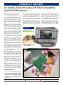
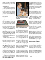
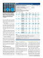
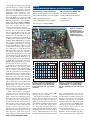
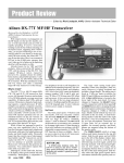
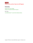
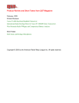
Product Review and Short Takes from QST Magazine
January, 2005
Product Reviews:
•
An Antenna Tuner and Audio DSP Filter for Elecraft K2 and K2/100 Transceivers
•
Alinco DJ-C7T Pocket-sized VHF/UHF FM Transceiver
Short Takes:
•
EasyLog5
Copyright © 2004 by the American Radio Relay League Inc. All rights reserved.
PRODUCT REVIEW
An Antenna Tuner and Audio DSP Filter for Elecraft K2
and K2/100 Transceivers
Reviewed by Larry Wolfgang, WR1B
Senior Assistant Technical Editor
When I built an Elecraft K2 and began
to operate with that radio, I realized that
this was no ordinary rig, kit or otherwise.
The original Product Review radio
included most of the options available at
the time—KSB2 SSB adapter and the
KNB2 noise blanker and the KBT2
internal gel-cell battery.1 I later added the
K160RX 160 meter module with separate
receive antenna jack and the KAT2
internal antenna tuner. With a couple of
controller upgrades along the way, I have
kept my K2 (serial number 495) quite
current with the latest revisions. When
Elecraft announced the KPA100 100 W
upgrade kit I added the amplifier, too.2
The KAT2 internal antenna tuner in my
low power K2 made it easy to use almost
any antenna. That made portable operation
a breeze. It was a versatility that I was
unhappy to lose when I wanted to operate
using the amplified K2. The ad copy for
the KAT100 external antenna tuner sure is
enticing! I wanted to add one to my station
as soon as possible. In addition, I had read
about the KDSP2 DSP audio filter board
option and I thought the interferencefighting features of a good DSP filter
might be worth adding.
I called Elecraft and ordered the
KAT100 and KDSP2 kits, along with
another firmware upgrade and a keying
waveform modification kit. (More on that
later.) Figure 1 shows my latest Elecraft
station package. When ordering the
KAT100, you will have to specify either
the KAT100-1 or KAT100-2 kit. I chose
the -1 version, which means the tuner is
packaged in a half-height cabinet,
designed to sit under the K2. The -2
package is without a cabinet, but comes
with front and rear panels to put into an
optional EC2 enclosure that will leave
room for other accessories. Tilt stands of
11/2 and 21/2 inch height are also available.
the Elecraft kits explain each step and
provide boxes to check off each step as it
is accomplished. Figure 2 shows the
contents of my KAT100 ready to start a
parts inventory. I used a few basic tools,
such as small needle-nose pliers, small
flush-cutting nippers and a temperaturecontrolled soldering iron. Before I started
building this kit I picked up a lighted
magnifying lens to view components, read
values and markings, and inspect my
solder connections. See Figure 3. This was
a huge help, and a bit easier to use than
my wife’s craft magnifier, which I used
when building the previous Elecraft kits.
A control cable goes between the tuner
and the K2 serial interface. This can
either be to the serial interface included
with the KPA100 amplifier or the KIO2
accessory. Interestingly, you can add the
Bottom Line
Another set of useful
features to add to your
K2—they just keep coming!
Figure 1—The Elecraft K2 on
top of the KAT100.
Building the KAT100
The assembly instructions with all of
1
L. Wolfgang, “Elecraft K2 HF Transceiver Kit,”
Product Review, QST , Mar 2000, pp 69-74.
2
L. Wolfgang, “Elecraft KPA100: A 100 W
Upgrade for Your Elecraft K2 HF
Transceiver,” Product Review, QST , Feb
2004, pp 76-80.
Figure 2—The unpacked KAT100 kit ready to be inventoried.
Joel R. Hallas, W1ZR
Assistant Technical Editor
[email protected]
From January 2005 QST © ARRL
KAT100 control cable in parallel with an
RS232 computer control cable, so both
the tuner and the computer interface can
be used at the same time.
Alignment and Test
After the construction is complete there
are a few tests and alignment steps before
you are ready to operate through the tuner.
I was pleased to see all the proper LEDs
light and the K2 main display acknowledge
the tuner when I first connected the tuner
and turned on the radio. The adjustments
are made by connecting a DMM between
ground and selected pins of the op-amp
used to measure forward and reflected
power for the SWR readout, as well as the
power calibration.
Circuit Overview
Eight series inductors and eight parallel
capacitors form an L network for the
KAT100 matching network. The inductance range is about 0 to 20 µH in 256
steps, and the capacitance range is about
0 to 2400 pF in 256 steps. The components
are rated so that the tuner can handle
150 W with an output SWR as high as 10:1.
The parallel capacitance can be switched
between the transceiver and the antenna
side of the tuner using one of the relays.
A relay also selects the ANTENNA 1 or
ANTENNA 2 connector.
Front-panel LEDs indicate whether
ANTENNA 1 or 2 is selected, and also
indicate whether the K2 is set to a power
level below 20 W (LOW) or above 20 W
( HIGH ). A 10 segment LED multicolor
bargraph indicates SWR—green from 1:1
to 1.5:1—yellow to 2.5:1 and red up to 5:1.
See Figure 4 for an inside view of the
completed KAT100.
Lab Test Engineer Michael Tracy,
KC1SX, noted that unlike other automatic
antenna tuners we have tested in recent
years, the KAT100 always tunes for the
best possible match instead of stopping
when it finds a match of (typically) 1.5:1.
Operating with the KAT100
The KAT100 requires a 10 to 15 V dc
power supply. Typical current drain is about
200 to 300 mA, although it can be as high
as 700 mA if all relays and LEDs are
activated at the same time. This might
occur, for example at the beginning of a
tune cycle, if the initial SWR were over 5:1.
Connect one or two antennas to the
antenna jacks, use a short jumper between
the K2 and the tuner RF INPUT , and
connect the serial control cable between
the two units. You should also connect
good ground wires to the ground screws
on the back panel of the tuner and the K2.
The tuner uses a transistor switch to
turn it on when the K2 is powered on.
From January 2005 QST © ARRL
Figure 3—A lighted magnifying lamp was
an excellent addition to my kit building
tools. Here I was working on the KDSP2
circuit board.
Figure 4—A view inside the completed
KAT100 automatic antenna tuner. Note
the front-panel LEDs.
The appropriate antenna indicator and
power level indicator will light up,
showing you that the tuner is ready to go.
The first time you select any band with
one of the antenna jacks, you will have
to press and hold the TUNE button on the
front of the K2. This will start a tune
sequence. As soon as the sequence starts
you can release the TUNE button. The
radio will reduce power to 20 W if you
had it set to a higher power level. If you
are using the tuner with the power set for
QRP operation, it will decrease power to
2 W. (The tuner will operate with the
transmitter power set as low as 0.2 W.)
The microcontroller will step through the
relay positions and measure the SWR to
seek the best match conditions. Within
about 1 to 5 seconds you should notice
the SWR bar graph indicators on the tuner
drop to between 1:1 and 1.5:1.
The next time you come back to a band,
the microcontroller will automatically set
the relays to the saved tuner and antenna
port settings for that band. As you tune up
or down the band, the SWR indicator LEDs
on the tuner will show you if the SWR
starts to increase. In that case you will have
to press and hold the TUNE button again.
It is worth mentioning that this is a
bit different than what I first expected of
an automatic antenna tuner. At least with
some automatic tuners, if the tuner senses
an SWR higher than some predetermined
level, such as 2:1 or 3:1, the tuner will
go into a tune cycle automatically to
correct the mismatch. While the KAT100
senses SWR and displays it on the LED
bar graph, it does not automatically go
into a tune sequence.
You can also use the K2 to read the
various L and C settings. The ATU menu
selections of Lxx.x and Cxx.x show the
present settings in µH and nF. You can
also select individual inductor and
capacitor settings directly from the menu.
These features would be useful if you
have a problem with your tuner and have
to troubleshoot the operation.
My first operation with the KAT100
was for Field Day 2004. My wife Jean,
WB3IOS, and I went camping at
Burlingame State Park in Charlestown,
Rhode Island. I used a 20 foot telescoping
fishing pole and about 35 feet of number
10 wire. Near the middle of the pole I
wound the wire into a large coil. Then I
continued with the wire straight to the
base of the pole. Three guy ropes and
stakes held my vertical antenna in the
field at the front of our campsite. I ran
six radial wires along the ground and
connected a piece of coaxial cable to the
antenna and ground system.
The KAT100 tuned that antenna on all
bands, 80 through10 meters, and we had a
great time. The tuner and radio operated
flawlessly, with the radio operating at 100
W all weekend. We powered everything
from a large gelled electrolyte battery, with
a small solar panel and the Micro M Plus
charge controller from The ARRL
Handbook. 3 This illustrates one great
feature of the K2 station. Even with the
KPA100 100 W amplifier installed and
using the KAT100 automatic antenna
tuner, this station is designed to operate
efficiently from battery power.
Firmware Upgrade and Keying
Waveform Modification
Elecraft is always looking for ways to
improve their products. As changes are
made to the circuitry and firmware for the
various microcontrollers, they publish the
information and make upgrade kits
available. One small circuit change came
out shortly after I completed building the
KPA100 amplifier.
There had been some discussion about
the CW keying bandwidth of the K2, and
many other modern transceivers, for that
matter. The sharp turn-off on key-up on
most radios can cause a slight click at the
3
D. Reed, Editor, The ARRL Handbook for
Radio Communications , 2005 Edition,
p 17.41.
Table 1
Elecraft KAT100 Automatic Antenna Tuner
Manufacturer’s Specifications
Measured in ARRL Lab
SWR range matched: Up to 10:1 typ (varies with band,
smaller range on lowest bands).
Tuning time: 1-5 seconds typical for initial tune-up,
<1/2 second to recall stored settings.
SWR display: 1.0:1 to 9.9:1 (on K2 LCD); 1:1 to 5:1 on
10 front panel LEDs.
Current drain: 200-300 mA typical, 700 mA max.
Enclosure size: 1.3 × 7.8 × 8.3 inches (HWD).
Weight: 3 pounds (approx).
Figure 5—This is the modified CW keying
waveform for the K2/100, showing the
first two dits in full-break-in (QSK) mode.
Equivalent keying speed is 60 WPM. The
upper trace is the actual key closure; the
lower trace is the RF envelope. Horizontal
divisions are 10 ms. The transceiver
was being operated at 100 W output
on 14.2 MHz.
end of every Morse element. A growing
consensus seems to be that a key-up wave
shape that more closely matches the
slightly rounded key-down characteristic
is more desirable.
This modification requires main
controller firmware revision 2.04H or
later and I/O controller firmware version
1.09 or later. You can check the firmware
version of your K2 by holding any frontpanel button while turning on the radio.
The display will show the firmware
revisions.
The keying bandwidth mod involves
cutting a trace on the control board,
replacing one diode with a resistor and
replacing a resistor and a capacitor. It also
involves adding a monolithic ceramic
capacitor and an electrolytic capacitor on
the bottom of the control board. One
diode on the bottom of the RF board must
be replaced by a PIN diode.
As expected, the instructions clearly
explain the steps involved, and a pair of
illustrations help you find the appropriate
locations for the control board changes.
The whole process took me about a half
hour. I brought my K2 into the ARRL Lab
and asked Michael Tracy, KC1SX, to
measure the new keying waveform. Figure
5 shows the results, which matched the
sample shown in the modification
Instructions.
KDSP2 Audio DSP Filter
This kit includes one small bare circuit
board to be “stuffed” and another small
circuit board that is already built, including
the DSP processor. The first board will
plug into the right side of the K2 control
board. If you already have the KAF2 audio
filter installed, the KDSP2 module will
replace it. If your radio does not have the
audio filter, you will have to make a couple
of small modifications to the K2 control
See below.
Not tested.
Load (Ω)
Band:
160
80
40
20
10
16:1
3.125
Input SWR
SWR BW %
Power Loss %
No match
Note 1
Note 2
No match
Note 1
Note 2
1.8:1
Note 1
Note 2
1.6:1
Note 1
40
1:1
6
<10
8:1
6.25
Input SWR
SWR BW %
Power Loss %
3.0:1
Note 1
Note 2
1:1
20
<10
1:1
15
20
1.4:1
Note 3
35
1:1
11
12
4:1
12.5
Input SWR
SWR BW %
Power Loss %
1:1
>203
<10
1:1
31
<10
1:1
25
10
1.1:1
28
20
1.1:1
28
15
2:1
25
Input SWR
SWR BW %
Power Loss %
1:1
>334
<10
1:1
63
<10
1:1
60
<10
1:1
70
12
1:1
79
<10
1:1
50
Input SWR
SWR BW %
Power Loss %
1:1
>100
<10
1:1
>100
10
1:1
>100
<10
1:1
>100
<10
1:1
>100
14
2:1
100
Input SWR
SWR BW %
Power Loss %
1.2:1
100
<10
1.2:1
94
<10
1.1:1
47
10
1:1
27
<10
1:1
16
24
4:1
200
Input SWR
SWR BW %
Power Loss %
1:1
28
<10
1:1
29
<10
1:1
28
<10
1:1
26
<10
1:1
16
22
8:1
400
Input SWR
SWR BW %
Power Loss %
1:1
17
19
1:1
17
18
1:1
11
16
1:1
16
<10
1:1
8
25
16:1
800
Input SWR
SWR BW %
Power Loss %
1:1
11
13
1.1:1
11
20
1:1
11
20
1:1
9
25
1:1
6
30
SWR
Notes
1
The span of frequencies between which the SWR is 1.5:1 or less could not be determined
because the minimum SWR was not better than 1.5:1 in this band.
2
A reasonable match must first be obtained in order to measure loss.
3
1.5:1 SWR BW could not be measured in this case due to difference in SWR measured by
external means and SWR as reported by the K2.
4
SWR was below 1.5:1 at the lower frequency limit, so the exact 1.5:1 SWR bandwidth could
not be measured.
board to accept the KDSP2 board.
Building the DSP board was pretty
easy. There were no toroids to wind or
trimmers to tweak. In fact, the most
difficult part of the assembly was bending
the leads on the monolithic ceramic
capacitors to make them fit close to the
circuit board.
Before putting the top cover back on the
K2, the instructions called for me to turn
on the K2. All of the proper display items
came up as I went through the rest of the
initial checkout procedures.
Operating the KDSP2
The KDSP2 provides four audio filters
each for SSB and RTTY. In effect it
provides eight filters for CW because each
of the four filters have both a “normal” and
a “soft” filter setting. The soft selection
provides slightly less skirt selectivity than
the normal filter, but has a bit better
ultimate rejection outside the passband.
The soft filters may also have slightly less
ringing at the narrowest bandwidths.
The default filter settings seem to
provide a good set of choices for each
mode. These filters are selected by pressing
the AFIL button on the K2. If you have your
K2 crystal filters set to a center frequency
other than 600 Hz, you will have to adjust
the CW filter center frequencies. If you
would prefer a different set of bandwidths
you can change those as well. Likewise, if
From January 2005 QST © ARRL
you don’t like the default settings for low
and high frequency cutoff for the SSB
filters, you can change those to suit your
preferences. The RTTY filters also have
adjustable center frequencies and
bandwidths. I won’t describe the entire
process of setting these filter parameters in
this review. Suffice it to say that you will
tap the DISPLAY button and then press and
hold RCL a few times to reach the filtersetting menu. Then the BAND+ and BAND–
buttons adjust the filter values up and down.
Your new settings will be stored
automatically for that filter selection.
Figures 7 and 8 show some of the filter
response curves measured in the ARRL
lab. One default filter setting for each
mode is LOW PASS. Basically this filter
setting leaves the DSP filter wide open.
The low pass filters have a bandwidth of
2.5 kHz in CW, 3 kHz in SSB and 3.5 kHz
in RTTY. With LOW PASS selected, the
radio response will follow the selected
crystal IF filter passband shape. Selecting
the narrower DSP filters will increase the
passband skirt selectivity. You can select
any combination of crystal IF filter and
DSP audio filter setting for each mode.
For example, if I really want to eliminate
nearby signals while trying to copy a CW
signal I might select the 200 Hz crystal
filter and the 100 Hz DSP filter. If
necessary, I could even set the DSP filter
to 50 Hz. That is pretty tight! One of the
KDSP2 menu options allows you to put the
filter in bypass mode to save power.
In addition to the band-pass filters, the
KDSP2 provides a very effective noise
reduction filter for CW and SSB modes,
and an automatic notch filter for SSB
mode. To activate the noise reduction, tap
the Display button to see the primary filter
display menu. Figure 1 shows the K2
displaying this menu. That display
indicates that SSB filter 2 is in use. The
decimal points in front of the nr and nt
indicate that both the noise reduction and
the auto notch filters are active. Tap the
BAND+ button to activate the noise
reduction and tap it again to deactivate it.
You can select noise-reduction levels from
1 to 4 by holding the STORE button.
Noise reduction level 1 is incredibly
effective. You go from listening to
background noise as you tune across the
band to hearing no background noise at
all. Signals just pop out of the silence as
you tune. It can be a bit unnerving,
because it sounds like the radio is dead
until you tune across a signal. Of course,
if you find some band conditions that
require a more aggressive noise
reduction, select one of the higher levels.
That will also add some distortion as the
filter suppresses some of the speech.
Interestingly, the DSP denoiser actually
From January 2005 QST © ARRL
Table 2
Elecraft KDSP2 DSP Module for K2 Transceivers
Manufacturer’s Specifications
Measured in the ARRL Lab
Noise reduction: Adaptive, level not specified.
20-30 dB (setting dependent).
Tone reduction: Adaptive, level not specified.
33 dB, 52 dB with noise reduction.
Audio response: Not specified.
See Figures 7 and 8.
Power requirements: 13.8 V dc, 0.06 A.
Not measured.
Size: 2.1 × 3.1 × 1.2 inches (HWD).
Figure 6—The KDSP2
plugged into the K2
Control board. Note the
filter circuit board and
the DSP processor
module plugged into it.
0
0
Reference Level: 0 dB
Reference Level: 0 dB
–10
–10
–20
–20
–30
–30
–40
–40
–50
–50
–60
0.0
0.2
0.4
0.6 0.8 1.0 1.2 1.4
Audio Frequency: 0 to 2 kHz
1.6
1.8
2.0
–60
0.0
0.4
0.8
1.2 1.6 2.0 2.4 2.8
Audio Frequency: 0 to 4 kHz
3.2
3.6
4.0
Figure 7—Passband of the KDSP2 filter in
CW mode. Red trace is 100 Hz, blue is
250 Hz and black is 800 Hz bandwidth.
Low pass (no DSP) and “soft” settings
not shown.
Figure 8—Passband of the KDSP2 filter in
SSB mode. Red trace is 1.3 kHz, blue is
1.6 kHz and black is 2.2 kHz bandwidth.
Low pass (no DSP) and “soft” settings not
shown.
improved the noise floor and the IMD
dynamic range by a few dB.
The automatic notch filter is a “seek and
destroy” filter for carriers that appear on
frequency in the middle of your QSO.
Whether it is someone tuning their tubetype amplifier or adjusting an antenna tuner,
the auto notch filter will remove
the carrier. It is also quite effective at
eliminating short wave broadcast carriers
on 40 meters. The auto notch also makes it
easier to actually listen to those short wave
broadcast stations on 40 meters. I found
the received AM audio to be easier to
understand with the notch turned on and
the radio tuned very slightly off zero beat.
Beginning with release 2.04, all DSP
functions can be turned on or off from the
front panel without use of the menu system.
Part of the beauty of the KDSP2 is that
it allows you to experiment with different
settings for the noise reduction and
autonotch filter parameters.
Another range of adjustments for the
DSP filters involves the filter gain. There
are five gain menus for you to adjust. The
idea is that you can balance the system
gain for the various types of signals. You
can set the gain of the band-pass filters
by mode. In addition you can set the SSB
noise reduction gain as well as the CW
noise reduction gain.
Oh, And There is a Clock, Too!
As if all this isn’t enough, the KDSP2
also includes a real time clock and
calendar. The clock provides date and time
readouts on the K2 display, and includes a
lithium battery to keep the clock running
even without connection to the supply.
Changing the minutes when you set the
clock will zero the seconds to synchronize
with WWV. You can enter the time display
from any DSP menu by pressing and
holding the STORE and RCL buttons
simultaneously.
A Few Nits to Pick
I don’t suppose any Product Review
is complete without pointing out a few
things the author didn’t like about the
product, or at least a short wish list of
features to add.
The clock is a good example to illustrate a problem that began to become
apparent to me during the KDSP2 phase
of this review. You can either display the
time, or the date, or the operating frequency or other menu options on the K2 display.
If I have to hit the DISPLAY button to go to
a DSP menu, and then hold STORE and
RCL every time I want to see the time, to
log a contact, then the clock seems a little
less useful. Turning the main tuning dial
returns the display to the operating
frequency. As long as you don’t change
mode or filter settings, the clock display
will come back if you hit the DISPLAY
button, but if you change any of those
settings, then you will have to go through
the DSP menu to recall the clock.
The menu choices and the methods
of accessing the various menus on the
K2 is becoming much more complex as
all these new features are added. With
every button serving two functions, and
with those functions printed above and
below the buttons, I have always found
the K2 operation to be quite intuitive. I
may simply need more time to become
familiar with the new options, but my
feeling is that my K2 has started to go
beyond intuitive operation. Until now I
have seldom needed to pull out the
operating manual to remember how to
access a certain function.
I have to wonder how much more
Elecraft can add to the K2 with the current
single-line display and menu system.
Perhaps it is time to think about a mod
that adds a multi-line display or even a
larger package that could include a few
more buttons, switches and other controls.
The K2 started out as a great radio that
has gotten even better with new features
added. Where will they go from here?
Manufacturer: Elecraft, PO Box 69,
Aptos, CA 95001-0069; tel 831-662-8345;
fax 831-662-0830; www.elecraft.com.
Price: KAT100-1, $239; KAT100-2, $219;
KDSP2, $219.
Alinco DJ-C7T Pocket-sized VHF/UHF FM Transceiver
Reviewed by Rick Lindquist, N1RL
Senior News Editor
For some time now, I’ve marveled as
cellular telephones have at once become
smaller and slimmer, more feature-laden
and fit unobtrusively in a shirt or jacket
pocket. So, to balance out that super
model-skinny cell phone, here’s a
comparably diminutive Amateur Radio
dualbander for that other pocket. Dick
Tracy, eat your heart out!
It’s been a long time coming, but
Alinco—the manufacturer that amazed
the amateur market in the late 1990s by
pioneering its series of so-called “credit
card” handhelds (see “Alinco’s Amazing
Credit Card H-Ts,” QST, Oct 1998)—now
has trumped its own ace with the DJ-C7T.
A direct descendant of 1998’s dualband
DJ-C5T (itself the progeny of the even
tinier DJ-C1T and DJ-C4T), the DJ-C7T
reflects further evolution in several
respects. In fact, Alinco refers to it as a
“new generation credit card-sized VHF/
UHF dualband micro transceiver.”
front-panel space, combining control
functions on a single button or its one
rotary knob. This makes for a somewhat
steeper learning curve, but with few
exceptions, it’s not a daunting one.
Reading the appropriately pint-sized
Instruction Manual is a must, however.
But size and strength aren’t everything.
The C7T more than makes up for its
300 mW of RF (500 mW with an external
6.5 V dc supply) by providing listen-only
access to the FM broadcast band, the AM
aircraft band and a wide expanse of VHF
and UHF spectrum outside the amateur
bands. It also offers a whopping 200
memory channels as well as a priority
channel and five pairs of programmed
scan-limit channels.
Some features we’ve come to know and
love on our larger handhelds are absent on
the C7T. For starters, there’s no—gasp!—
DTMF touchpad. While it’s a dualbander,
full duplex operation is not available,
although it is possible to transmit on VHF
and receive on UHF—or vice versa.
No surprise: The teeny, thin speaker
doesn’t sound like a Bose Wave. At top
volume while listening to an FM broadcast station, I found the sound loud, clean
and crisp, although lacking any thumping
bass. On the ham bands, it’s “good communication quality.”
Another thing: While the receiver in the
C7T is an improvement over the C5T, it’s
not going to perform like your higherpriced mobile or maybe even your heavier-
Figure 9—The
compactness of this radio
is evident as it’s almost
lost in the author’s hand.
Tiny is as Tiny Does
Let’s be clear up front: Like the DJC5T before it, the DJ-C7T is petite not
just in terms of size but also in power
output. As is the case with most 300 mW
class transceivers, when operating from
its internal battery, it hears much better
than it hollers. The unit’s size means it
also must make the most of available
Figure 10—While not quite as slim as a
credit card, this radio won’t make a big
bulge in your pocket.
From January 2005 QST © ARRL
duty handheld in areas where various VHF
and UHF signals—not just amateur—
proliferate. The receiver’s dynamic range
hovers in the low 50 dB range in both ham
bands. This level of performance does not
offer a great deal of protection against
infiltration from nearby in-band signals—
or even signals in adjacent commercial
bands, including Public Safety, paging
systems and even broadcasters.
Speaking of specs: The manual that
came with this radio includes a specification table different from what the Alinco
engineers intended. The correct specs can
be found on their Web site. When we first
tested a sample we let the manufacturer
know that it wasn’t meeting their specs and
they determined that their document folks
had grabbed the wrong numbers. Our Table
3 reflects the updated specs.
Catching Up With the
“New Generation”
In the C7T, active amateurs—and
especially frequent travelers—will find a
multi-featured, extremely small and
lightweight, albeit flea-power, VHF/UHF
transceiver that they literally can take
anywhere—except swimming. Over the
few weeks of running it through its paces,
I’ve tossed it into my briefcase or just
stuck it into a shirt or jacket pocket to
take along on the road (remembering not
to send it to the cleaners or laundry). At
3.6 ounces (including the battery) and
less than 4 inches tall, it’s still “wicked
rugged,” as New Englanders say. As the
manual notes, however, while the C7T
has been tested for “anti-shock and/or
against drops for daily use,” it is not built
to military specifications.
Once you’ve pocketed the C7T, the only
thing to remind you it’s there likely will
be the nearly 4.5-inch flex antenna sticking
out. By the way, Alinco used an SMA
antenna jack this time, so you can swap
out for a larger antenna if you’d prefer.
The C7T sports a sturdy, gently tapered
two-tone (silver-gray and black) plastic
case. The 3.7 V, EBP-58N 600 mAh
lithium-ion battery, about the size of some
of the larger-format digital camera storage
cards but about twice as thick, snaps neatly
and securely onto the bottom rear of the
unit. It’s very simple to remove and
replace, should you spring for a spare.
The LCD display, while not back
lighted, is sizeable for such a tiny
Bottom Line
An awesome pop-in-your-pocket,
take-anywhere dualband mini
handheld that’s a decent ham band
performer and a whole bunch of fun.
From January 2005 QST © ARRL
transceiver. About 1.5 inches across and
a half-inch high, it dominates the upper
quarter of the transceiver’s front panel.
The frequency readout font is large and
highly visible, even from a couple of feet
or so away. You can even see the smaller
memory channel number and the vertical
uncalibrated bar graph style S/power
meter, which I didn’t find terribly useful.
In addition to frequency and memory
number, the display conveys lots of other
vital information. The display indicates
mode and whether certain features are
enabled, such as APO (auto power off)—
the C7T sends END three times in Morse
when it’s about to shut itself off—or BS
(no, it means “battery save”)—a tiny battery icon tells you you’re running out of
steam. An asterisk (*) indicates you’re in
repeater mode. The typical + and – symbols tell you the repeater offset direction,
while T/SQ symbols let you know when
CTCSS tone (or European tone burst)
and/or tone squelch is enabled.
Immediately below the display are five
multifunction pushbuttons, stylishly arrayed in two slight arcs—three above and
two beneath—just above the speaker grille,
which occupies the rest of the front panel.
Topping off the transceiver, in addition to
the rubber duckie, is a multifunction rotary
control (which Alinco refers to as the
“dial”). On the left side are the push-to-talk
and the MONI(tor)/STEP buttons.
A tiny front panel LED glows red
when you’re transmitting and green when
a signal breaks squelch.
The unit has two jacks. The MIC/EAR
jack accepts a small (mono) plug, not the
more common 3.5 mm variety (some other
transceivers have gone to these as well).
Another tiny coaxial jack on the right side
Table 3
Alinco DJ-C7T, serial number M000663
Manufacturer’s Specifications
Measured in the ARRL Lab
Frequency coverage:
Receive, 88-108 MHz (WFM),
108-136 MHz (AM), 136-174 MHz,
380-512 MHz (FM);
transmit, 144-148 MHz, 420-450 MHz.
Receive and transmit, as specified.
Power requirements: 3.7-6.0 V dc;
receive, 0.07 A;
transmit, 0.32 A (max).
Receive, 0.1 A (max volume, no signal);
transmit, 0.34 A. Tested at 6.0 V.
Receiver
Receiver Dynamic Testing
Sensitivity: 12 dB SINAD, VHF, 0.2 µV;
UHF, 0.25 µV; WFM, 0.7 µV.
FM, 12 dB SINAD, VHF, 0.2 µV;
UHF, 0.23 µV;WFM, 100 MHz, 2.4 µV.
Two-tone, third-order IMD dynamic range:
Not specified.
20 kHz offset from 146 MHz, 52 dB,*
10 MHz offset from 146 MHz, 64 dB;
20 kHz offset from 440 MHz, 53 dB,*
10 MHz offset from 440 MHz, 69 dB.
Two-tone, second-order IMD dynamic range:
Not specified.
VHF, 76 dB.
Adjacent-channel rejection: Not specified.
20 kHz offset from 146 MHz, 51 dB;
20 kHz offset from 440 MHz, 53 dB.
Spurious response: 60 dB.
IF rejection, VHF, 96 dB, UHF, 109 dB;
image rejection, V/UHF, 78/41 dB.
Squelch sensitivity: Not specified.
Threshold, VHF, 0.08 µV; UHF, 0.11 µV.
Audio output: 90 mW at 10% THD into
8 Ω (6 V).
97 mW at 10% THD into 8 Ω (6 V);
47 mW (battery).
Transmitter
Transmitter Dynamic Testing
Power output: 0.5 W (6 V); 0.3 W (battery).
146 MHz, 0.3 W; 440 MHz, 0.3 W with
EBP-58N battery pack;
146 and 440 MHz, 0.47 W; with 6 V dc.
Spurious signal and harmonic suppression:
60 dB.
VHF, 52 dB; UHF, 60 dB.
Meets FCC requirements.
Transmit-receive turnaround time (PTT release
to 50% of full audio output): Not specified.
Squelch on, S9 signal, V/UHF, 98/85 ms.
Receive-transmit turnaround time (“tx delay”):
Not specified.
VHF, 140 ms; UHF, 170 ms.
Size: 3.8 × 2.3 × 0.6 inches (HWD); weight, 3.6 ounces.
*Measurement is noise-limited at the value specified.
of the radio is for the charger or to connect
an external supply of up to 6.5 V dc.
audio not only crystal clear but very full
and natural sounding.
Getting Things Under Control
Visiting Other Radio Worlds
The gray front-panel pushbuttons bear
clear, white legends for their primary
functions—V/M (VFO/memory), SCAN,
BAND, PWR and FUNC . These access
major, secondary and, in some cases,
tertiary functions, and the most important
of these are spelled out in blue legends
above each button.
Sometimes, these buttons work in
concert with the tuning dial—another
feature the DJ-C5T managed without. For
example, to change frequency in 1 MHz
increments, just press and hold the BAND
button while twirling the tuning dial up
or down. Access other functions by
pressing and holding the button. To lock
(or unlock) the controls, for instance, you
press and hold the FUNC button (a small
key icon appears on the upper part of the
display window).
The other primary uses for the tuning
dial are to set the volume level and the
squelch level. Push the knob once and you
can set the volume anywhere between 0 and
30. Pushing the knob twice puts you into
squelch mode. The squelch setting is not
band exclusive. The range is from 0 to 9.
To set various global parameters, press
FUNC and the tuning dial in quick
succession. Pushing the tuning dial
further steps through the various settings,
accompanied by beeps (if beep is
enabled) that run up the musical scale
with each knob press. The parameters
include audio volume level to the
earphone jack (high or low), antenna type
(the C7T lets you use either an antenna
connected to the SMA jack or the
earphone cord as an FM broadcast
antenna), repeater function (see below),
tone burst frequency (there’s a choice of
four), auto power off, battery save (on or
off), beep (on or off), bell (rings when a
station breaks squelch on a channel
you’re monitoring), memory write
protect, scan type (“busy” or “timer”),
and AM/FM (you can only swap receive
mode after selecting a particular tuning
step but not in “auto” tuning step mode).
It was, of course, great to be able to
tune in the FM broadcast band (88.1 to
108 MHz, wideband FM mode). The C7T
also tunes the “AM aircraft” band, 108136 MHz—fun for long waits between
flights—as well as FM (or AM if you’d
like) from 136 to 174 MHz on VHF and
380 to 512 MHz on UHF.
By programming lower and upper
frequency limits, you can set up the C7T
to scan bands or entire swaths of
spectrum. The unit will, of course, also
scan just the memories you’ve already
programmed, and you can choose
between BUSY and TIMER mode to
determine how the unit reacts when it
detects a busy frequency or channel.
In BUSY mode, scanning stops when
a signal breaks squelch, and the receiver
remains on that frequency until the
receiver squelches again. In TIMER mode,
it stops for 5 seconds—typically just long
enough for you to decide if it’s something
you want to hear—before moving on. The
TIMER mode eliminates the annoyance of
having the receiver lock onto stray signals
leaking from the local cable TV system,
for example. Kudos to Alinco for
including this scanning option. I found it
very handy.
The C7T also will scan signals and
detect the CTCSS tone ( TONE SCAN).
That’s a nice feature to include, especially
with more and more repeaters migrating
to tone squelch operation in repeater-rich
regions.
With an accessory cable, it’s possible
to “clone” the memories of one C7T into
another unit.
On the Air
As noted, you won’t be able to hit
anything beyond the local machines (your
mileage will vary, of course), but 300 mW
goes a long way, and I had no problem
accessing repeaters 15 or so miles away
on both VHF and UHF.
I judged the transmit audio quality as
excellent. Eliminating the repeater as a
variable, my wife and I swapped handhelds and worked each other on simplex.
We both considered the C7T’s transmit
Experience Doesn’t Always Count
Now, most of us fairly experienced in
using the typical handheld transceiver can
figure out quickly and intuitively how to
get any radio up and running. That’s not
always the case with the C7T. All too
often, the manual would start to describe
how to enable or use a particular function
in one section only to send you elsewhere
to get the details. On occasion, I found
myself flipping back and forth to grasp
the big picture.
You’d think details on how to set up
the C7T for repeater use would be right
up there among the initial major points
the manual covers. Not so. REPEATER
FUNCTION (a parameter setting item)
isn’t even covered until page 24 of the
manual’s 32 pages. Additionally, it
doesn’t become clear until you’ve
thoroughly pored through the manual at
least once that the transceiver can be set
up either manually or automatically for
repeater operation, or, for that matter, that
manual settings override automatic ones.
Automatic repeater function means
having to figure out how to tell the
transceiver where to swap from negative
to positive offset and vice versa—
typically at 147 MHz in the US. As the
manual explains, “Prior to set [sic] this
parameter, edit a lower limit frequency
(the shift direction and the CTCSS tone
if requires [sic]) in the VFO mode and
store it to AL memory channel.” Then,
“Edit a higher limit frequency to AH
memory channel.”
While we’re on the topic of memory
programming, the C7T doesn’t let you
dump the contents of a memory back into
the VFO. Memories are not “tunable”
either.
Other operations were less confounding. It took a bit of initial experimenting
and, finally, a trip to the manual to write
to memories (it’s also pretty easy to
overwrite a memory unless you enable the
memory protect feature).
Clearly, this skimpy booklet with its
small typeface needs a bit of beefing up.
A Quick Reference Guide of some kind
spelling out basic, how-to-get-on-the-air
steps clearly and concisely would also be
a welcome addition.
Manufacturer: Alinco, www.alinco.
com/USA.html or Ham Distribution, Inc
(Alinco), 15-B5 S Trade Center Pkwy,
Conroe, TX 77385; tel 936-271-3366.
Price: $169.99; EDH32 external power
cable, $19.99.
Going Once,
Going Twice . . .
The ARRL-purchased equipment listed
below is for sale to the highest bidder.
Prices quoted on the Web page are the
minimum acceptable bids, and are
discounted from the purchase prices. All
equipment is sold without warranty except
as noted.
Details of equipment offered and
bidding instructions can be found on the
ARRL members’ Web page at www.arrl.
org/prauction. The following items are
available for bid in the January auction:
• ICOM IC-7800 200 W deluxe HF and
6 meter transceiver,
• Kenwood TS-480SAT mobile or fixed
HF and 6 meter transceiver,
• Spi-Ro AS-2 portable HF antenna,
• Elecraft XV-144 2 meter transverter,
• Palstar AT1500Bal balanced HF
antenna tuner,
• Wavenode WN-1 power meter with
software display.
From January 2005 QST © ARRL
By Steve Ford, WB8IMY
EasyLog5
E
asyLog5 is a complex piece of software. That is both a
compliment and a caution.
This is not merely a computerized ham log. EasyLog5
will control your radio (if your radio has computer-control
capability), manage awards, allow you to send CW, send and
receive PSK31 and PSK63, send pre-recorded audio (“voice
keying”), monitor your favorite DX cluster and more.
And when I say “more,” I really mean much more. The folks
at Microware Software have done their utmost to create the ultimate do-everything Amateur Radio application for Windows.
Whether they’ve succeeded is ultimately up to the judgment of
each user. One thing is certain, though: with its multiplicity of
features, EasyLog5 takes some time to explore and master. Does
that mean that “EasyLog” is an oxymoron? Not at all. Each function is easy to use; it is just that there are so many of them!
Tailoring EasyLog5 to Yourself
Like most EasyLog5 users, I find that I use some features
frequently and others not at all. I love the ability to have up to
five separate logs open at once, jumping between them by clicking on the folder tabs at the right side of the main window.
As a PSK31 operator, I found this portion of EasyLog5 particularly enjoyable. My only gripe is that one of the receive
windows prints yellow text on a red background. That’s difficult for my middle-aged eyes to discern and there is no way to
change the color scheme.
I used the radio control feature with my Yaesu FT-897 transceiver and it worked quite well. A small window pops up and
allows you to select frequencies and modes as you please.
The DX cluster function is terrific, especially in its ability to
filter spots. For example, I set mine up to show only RTTY spots
from North American stations, on 40-10 meters, for DXCC entities I haven’t worked or confirmed. On busy evenings when I
can’t spend hours at the radio, this is a wonderful feature.
Perhaps my favorite EasyLog5 feature is the “Running”
mode. In this mode you are presented with multiple QSO entry and checking windows. During a contest, or during normal
operation, you can type in a call sign and instantly know if
you need that zone, prefix, state, DXCC entity, etc for an award
or contact credit on a given band or mode.
The EasyLog5 main window.
The world map window. In this instance, the DXCC entities I’ve
confirmed on RTTY are highlighted in yellow.
My Wish List
EasyLog5 has almost everything I could ask for in a station
logging/management application. But like anyone else, I have
my wish list for future versions.
• I wish EasyLog5 supported the VHF/UHF Century Club
award with the ability to quickly tell me which grid squares
I’ve worked and confirmed, especially in the Running mode.
• I wish some of the remnant Italian language text labels
(Microware is an Italian company) were rendered in English.
In the world map display, I know “sole” means “sun,” but it is
still a little jarring.
• I wish I didn’t have to input my approximate location as
a six-character grid designator. Most hams in the US only use
four-character grid square designations, such as “FN31.”
All this aside, EasyLog5 is still a highly capable, welldesigned application. If you are curious, my advice would be to
download the free trial version at www.easylog.com/eng/
index.htm (click the “Now available—the trial version! Download it!” link). Just bear in mind that you probably won’t be
able to fully explore EasyLog5 in one sitting. Be patient, take
your time and, above all, read the manual.
Manufacturer: Microware Software. Distributed in the United
States and Canada by J. B. Sims Services LLC, PO Box 550895,
Dallas, TX 75355-0895; jbsims_services.home.att.net/. $89.54.
System requirements: Pentium or AMD processor, 400 MHz or
better, RAM 128 MB or greater, Windows XP, 2000 or NT.
From January 2005 QST © ARRL