1
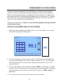
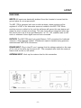
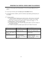
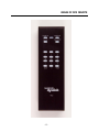
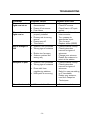
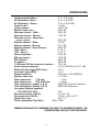
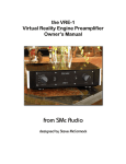
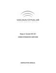
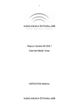
Magnum Dynalab MD 109
TRIODE REFERENCE FM TUNER
featuring the
WORLD SOURCE PLATFORM
INSTRUCTION MANUAL
-1-
TABLE OF CONTENTS
A MESSAGE FROM THE PRESIDENT
3
UNPACKING YOUR MD 109
4
CONTROL FUNCTIONS
5
IMAGE OF MD-109 FRONT PANEL
6
INSTALLING THE MD 109
7
PROGRAMMING THE TOUCH SCREEN
10
LAYOUT
11
RECEPTION TECHNIQUES
12
FM RECEPTION AIDS AND ACCESSORIES
13
OPERATING THE CONTROL SYSTEM USING THE HANDHELD
14
IMAGE OF RC2 REMOTE
15
TROUBLESHOOTING
16
SPECIFICATIONS
17
SAFETY SHEET
18
LIMITED WARRANTY
19
-2-
A Message from the President
Thank you for choosing the Magnum Dynalab MD 109 Reference FM Tuner
complete with our World Source Platform. Great care has been taken in the
design, manufacturing and selection of components for the MD 109 Tuner in
order to ensure many years of listening enjoyment.
The MD 109 is the culmination of years of research and development. We have
expended considerable effort at every phase of the design process to achieve the
highest level of performance. We have used only the finest components
throughout the unit, including a separate large torroidal transformer for the audio
stage, which incorporates our new TRACC technology (Triode Reference Audio
Control Center).
We appreciate your decision to purchase the MD 109 FM tuner. Please feel free
to contact us if you have any comments or suggestions on improving your FM
listening experience. You may call us on our toll free number (1-800-551-4130)
or via our direct line when outside North America (1-905-791-5888) or contact
us via email at: [email protected]. We at Magnum Dynalab are here to
serve your audio source needs.
Respectfully yours,
Larry Zurowski
President
-3-
UNPACKING YOUR MD 109
Carefully inspect all sides of the shipping carton for damage. If there are marks or
holes in the carton, make note of the location in relation to the unit inside. Any
obvious dents or scuffmarks should alert you to the possibility of damage. Open
the top flaps and carefully lift the transport case out of the carton. Carefully
remove the MD 109 from the box and wrapping, inspect all sides. Pay special
attention to the corresponding areas on the unit where damage if any was found
on the shipping carton. If damage is evident, document the type and extent of the
damage, then repack the unit and call the dealer.
If your unit was delivered by a common carrier (Eg. UPS) and you have found it to
be damaged, contact the carrier immediately for instructions.
KINDLY DO NOT SEND THE UNIT BACK TO THE SHIPPER UNTIL YOU HAVE BEEN
ASKED TO DO SO. SHIPPNG THE UNIT BACK PREMATURELY MAY VOID ANY
CLAIM FOR DAMAGE THAT YOU MAY HAVE.
DO NOT DISCARD THE PACKING MATERIALS AND CARTONS. Should you need to
return the unit for any reason, it must arrive safely and suitably packaged in order
for our receiver to accept it from the carrier. Also, if the unit has incurred
damage as a result of improper packaging, it is not likely that a claim for the
damage against the carrier will be successful.
Likewise, when applicable we will ship your unit back to you only in factoryapproved packaging. However, if the unit were to arrive at our factory in anything
other than factory approved packaging, we reserve the right to re-pack the unit in
factory-approved packaging and charge the cost of the packaging to the shipper.
This is the only way we can assure you of a safe return (damage by carrier
excepted).
-4-
CONTROL FUNCTIONS
The MD 109 is equipped with an audio sensing circuit, which protects the unit
from any unsafe operating conditions. If an unsafe operating situation should
occur the unit will automatically be muted, and if the fault lasts more than two
minutes a light will flash on the circuit board and the unit will not come back on
until serviced
The following functions are displayed clearly on the touch screen. Each funtion’s
utility is explained below.
1. POWER: Controls the power to all display functions. When in the standby
condition the screen will display the Magnum Dynalab logo and the word power
in the lower left hand corner.
2. MUTE: Controls the elimination of inter-station noise. It is recommended that,
when receiving marginal signals, the mute be set to off. This will eliminate
intermittent loss of signals that fall below a specific signal value. The word
“mute” will appear on the screen when activated.
3. STEREO: Controls whether the tuner is operating in Stereo or Mono mode.
The word “stereo” will be displayed in the right hand corner of the screen when
you are in the stereo mode.
4. BAND: This switch controls the IF (intermediate frequency) selectivity. The
setting you are on will be displayed in the top right hand corner of the screen.
The different settings are described below.
a. Super Narrow: Controls the IF super narrow setting. This setting should
only be used in extreme reception conditions of adjacent channel
problems. The words super narrow will be displayed on the screen when
activated with the Band switch.
b. Narrow: This setting combines excellent frequency response with high
adjacent channel selectivity. The word narrow will be displayed on the
screen when activated by the Band switch.
c. Wide: Controls the ultra wide IF setting and offers the best frequency
response. The word wide will be displayed on the screen when activated
by the Band Switch.
5. DIM: When activated, the brightness of the screen will be reduced by 50 %;
this will extend the life of the screen. The screen will automatically dim after 2
minutes of inactivity.
-5-
6. TUNING KNOB: Rotating this control drives a precision decoder that selects
the desired frequency. When fine-tuning manually you must turn the knob
slowly as the decoder is very precise.
7. METER: The left hand meter displays signal strength. The higher the number
the better the performance. The right hand meter displays center tune,
optimum operating position will be in the middle.
8. FREQUENCY DISPLAY: Displays the frequency that you are tuned to.
9. SELECTOR KNOB: this knob selects which mode the MD 109 is operating in.
When used as a tuner, FM will be shown on the left side of the screen. When
other sources are added to the MD 109, the knob will be turned to activate
the input for that source.
IMAGE OF MD-109 FRONT PANEL
LCD Touch Panel
Signal Strength
Center Tune
FM 91.1
SIGNAL
STRENGTH
CENTER
TUNE
Tuning Dial
Selector
-6-
INSTALLING THE MD 109
1. Position the tuner the shortest distance from your preamplifier. Avoid putting
the unit where there are extremes in temperature.
2. Make sure that the MD 109, with specially designed feet using Vibrapod
isolators, is safely positioned on a shelf designed to hold at least 60 pounds
(26.55 Kg)
3. Remove the AC cord from the pouch on the lid of the carrying case and plug it
into the AC receptacle at the rear of the unit. DO NOT PLUG THE CORD INTO
THE WALL POWER SOURCE AT THIS POINT.
4. Connect the tuner to your preamplifier using a set of cables consistent with
the caliber and type (balanced or unbalanced) of your system. Select the tuner
input on your preamplifier. Note: Be sure that the preamplifier is set to zero.
5. Connect the FM antenna and/or cable to the RF input on the back of the unit.
6. CHECK TO MAKE SURE THE UNIT IS SET UP FOR THE PROPER VOLTAGE
(check for unit’s voltage marked on rear panel) then plug the tuner’s AC power
cord into an AC power source. Be sure to use a continuous power source so
as to allow the stand-by mode feature to function properly. The tuner’s audio
output is muted in the stand-by mode.
7. The power switch on the rear of the unit must be put in the “on” position
8. When power is supplied the screen will be black. To turn on the touch screen,
touch it anywhere on the Magnum Dynalab logo, at which time the Magnum
Dynalab logo and the word “power” will be displayed.
-7-
9. To turn on the unit push the power button. At first the screen will display
“warming up” as the components are brought up to a safe operating condition.
Once the safe operating condition is attained, the screen that is associated
with the setting of the input knob will appear. If you are using it in the FM
tuner mode, FM will appear on the left side of the screen.
Note: Each time the tuner is turned “ON”, there is a 25 second delay before
the tuner will operate. A light click will be heard, indicating that the relay has
been activated and that power is available.
WARMING UP. . .
10. Once power has been initialized, the meters will light and the touch screen
will show a reading between 87.5 and 108.5. All control functions will appear
on the bottom of the screen and the default positions will show on the top
right corner.
a. Turn off the Mute switch
b. Set the Band switch to wide
-8-
STEREO
SUPER NARROW
BLEND
MUTE
PRESET 03
MONO
NARROW / WIDE
FM TUNER
99.1
POWER
STEREO
BAND
BLEND
MUTE
MHz
PRE
DIM
Extra Text
11.
To tune the tuner you have three options:
a. Use the tuning knob on the right
b. Use the tune up or down arrow with the MHz position displayed on
touch screen
c. Use the remote control using the tune up and down buttons
12.
The tuner is now in a safe operating mode.
13. To turn the MD 109 off push the power button on the screen, the screen
will become dark. To turn on the screen, touch the Magnum Dynalab logo or
turn the right hand knob.
-9-
PROGRAMMING THE TOUCH SCREEN
The touch screen is designed to last 10,000 hours. Once the unit has been
turned on and the touch screen has been activated it will be at full brightness.
After two minutes of inactivity (no touching) the screen will go into a sleep mode,
this sleep mode (50 % brightness) will lengthen the life of the screen. To activate
the screen touch any point on the Magnum Dynalab logo, use the remote hand
held or turn the right hand knob (tuning dial).
Cleaning the touch screen: Only use a very soft cloth (eyeglass cleaning cloth) with
a non-abrasive cleaner.
SETTING THE FM PRESETS FROM THE TOUCH SCREEN
1. With the screen displaying the FM frequency, touch the digits, a new screen
will appear depicting the preset grid.
STEREO
SUPER NARROW
BLEND
MUTE
PRESET 03
FM TUNER
1
2
3
4
5
6
7
8
9
S
0
P
POWER
STEREO
99.1
BAND
BLEND
MUTE
MONO
NARROW / WIDE
MHz
PRE
DIM
Extra Text
2. Tune to the station you wish to store, push the “S” button on the display and
then the preset location, you must use two numbers i.e.: 01. You must also
do this fairly quickly to insure storage. Repeat this procedure for up to 40
preset locations.
3. To scan the presets, push the button showing “MHz”, it will change to “ pre” if
you push the up arrow above it you will scan your presets going up, by pushing
the down button you will view the ones below. To return to “MHz”, push the “
pre” button.
4. To return to the main screen touch any point on the screen.
- 10 -
LAYOUT
REAR PANEL
INPUTS: All inputs are electrically isolated from the chassis to insure that the
ground plane is not compromised.
The MD 109 is equipped with two module windows, these windows will be
replaced if a DAC or an alternative source is added to the MD 109. When
another source is added to the unit the software will sense this new device and
setup the touch screen accordingly. This new input will be recognized when the
left hand knob is set to the input description i.e.: D1, D2, satellite radio or HD
radio or whatever future digital sources are connected.
OUTPUTS: The MD 109 uses high grade Neutrix, XLR connectors for balanced
output in a fully balanced system. Unbalanced output is handled using precision
manufactured WBT RCA connectors.
POWER INPUT: Plug in the AC cord, insuring that the voltage marked on the rear
of the unit is the same as the source AC. This receptacle also holds the external
fuse as well as the on/off switch.
ANTENNA INPUT: Hook up the antenna lead to this connection.
- 11 -
RECEPTION TECHNIQUES
Antenna Cabling:
The lead-in cable from the antenna is often the weakest link in the FM system.
Some time spent on selection and matching will yield dramatic results when it
comes to noise reduction in weak signals.
A good grade of 75-ohm coaxial cable will provide very sufficient signal passage,
along with effective shielding against interference. Without effective shielding your
coaxial cable can in fact become an antenna in itself. There are different grades
of 75-ohm cable, RG59/U (Suitable for 50 feet and less) and RG 6. RG 6 is the
better of the two and should be used in runs of 50 feet or more. The RG 6 has
quad shielding and 50 % less losses than RG 59/U.
A good type of RG 6 is Beldon 1189 A. Combine this cable with LRC connectors
and you will have an installation that will optimize the performance of your tuner.
The key to maximizing the efficiency of the system is insuring that all connections
are clean and tight, silicon grease on outdoor connections will insure good
performance over a long period of time. If you splice either cable, make sure that
exactly the same type of cable is used.
Types of Antennas:
Multi-element Yagi - This is a unidirectional antenna capable of pulling in very
distant stations due to its high gain. The higher the gain the better. These types
of antennas are directional and should be used with a rotor to get the maximum
benefit from the antenna. The directional feature helps eliminate multi-path
problems by allowing only the signal from the direction that the antenna is facing
to be picked up by the antenna and not the signals that come from different
directions.
Magnum Dynalab offers two Yagi antennae, the MD 6 FM or MD 10 FM
Vertical ½ Wave - This design offers ease of installation and operation. This type
of antenna is omni-directional, which means that it picks up stations coming from
all directions. No rotor is required to pull in stations from behind or the side. This
design also gathers more of the FM signal from the air, offering superior fidelity
over that of a standard bi-directional antenna. It also gives 2.5 dB gain to the
signal strength over that of a standard dipole.
If multi-path is a reception problem, try laying the antenna down in the horizontal
plane rather than the vertical plane. This type of antenna can be used indoors or
- 12 -
outdoors, but regardless of whether it is installed indoors or outdoors, the higher
that you can put it the better it will perform.
Magnum Dynalab offers the MD ST-2, an excellent vertical ½ wave antenna
Folded Di-Pole - This is the most common and simplest of all antennas; most
people are familiar with the folded di-pole you received with most electronics gear
(generally provided with a tuner or receiver). This piece of wire is bi-directional and
the performance of it is affected by the angle that the signal hits the piece of
wire. There are quite a number of di-pole antenna designs; they work well in areas
of strong signal strength.
Magnum Dynalab offers the SR-100 as an excellent, indoor folded di-pole.
There are many styles of antennas but all of them are based on one of these
types.
FM RECEPTION AIDS AND ACCESSORIES
We have already alluded to the importance of a good quality antenna which has
been designed and built with the reception of the FM bandwidth exclusively.
Should you encounter a situation in which you require more gain to the FM signal
or situations where you may need less gain AND better selectivity then the
Magnum Dynalab 205 “Signal Sleuth” may be of benefit to you.
The 205 is a FM signal processor/amplifier designed specifically for FM. If you
would like more information on this item, please feel free to contact us at any
time. Call us TOLL FREE 1-800-551-4130, email us at [email protected]
or visit us at www.magnumdynalab.com.
- 13 -
OPERATING THE CONTROL SYSTEM USING THE HANDHELD
1. To turn on the power push the on button, to turn the power off push the off
button
2. To tune up and down push the tune up and tune down buttons
3. To directly access a station, push the numbers representing the frequency of
the station.
4. To store presets:
a) Tune the station frequency you want to store, make sure you are tuned
perfectly tuned to the station (as indicated by the center tune meter).
b) Push store and then the preset location, must be two digits, i.e.: 01
c) Repeat steps 1 & 2 for other presets
d) To recall a preset, you can push the preset button and the number of
the preset you want.
e) To reset or purge the presets press “p” then “s” within 5 seconds.
Problem
Presets will not store
Probable Cause
Speed of entry of preset
position too slow
Distance
that
the Batteries are weak
remote will work is
very short
Tuner will not turn on
AC not connected
The infra red sensor is
blocked
- 14 -
Probable Solution
When entering the preset
location do it fairly quickly
Change the batteries
Three “AAA”
Check power cord
Remove anything sitting in
front of the unit
IMAGE OF RC2 REMOTE
- 15 -
TROUBLESHOOTING
PROBLEM
No sound, meter
lights are not on
No sound, meter
lights are on
Signal strength is
low
Reception is poor
POSSIBLE CAUSE
• Power cord
disconnected
• Power off at source
• Fuse blown
• Interconnect not
properly installed
• Preamp set to wrong
source
• Power amp off
• Tube failure
• Antenna not connected
• Wrong type of antenna
•
•
Station too far away
Antenna pointed the
wrong way
•
•
Antenna not connected
Wrong type of antenna
•
Cross talk from
neighboring stations
Multi-path is occurring
•
POSSIBLE SOLUTION
• Connect power cord
• Check AC source
• Check fuse in AC input
socket
• Check installation of
interconnects
• Turn preamp to
appropriate input
• Turn on amp
• Replace tubes (6922)
• Check antenna hookup
• Check instruction
manual for types of
antennas
• Change your antenna
• Rotate the antenna to
point at the station
• Check antenna hookup
• Check instruction
manual for types of
antennas
• Switch to narrow setting
on IF bandwidth
• Rotate your antenna,
read the Reception
Techniques
Intermittent sound
•
Mute switch is off
- 16 -
•
• Turn mute switch on
SPECIFICATIONS
Usable sensitivity- Mono –
0.7 u V 9.0 dBf
50 dB quieting – Mono –
2.0 u V 9.9 dBf
50 dB quieting – Stereo –
2.3 u V 20.0 dBf
Capture ratio –
1.5 dB
Image rejection –
125.0 dB
Signal to noise ratio –
80.0 dB
Alternate channel – Wide –
46.0 dB
Alternate channel – Narrow 70.0 dB
Alternate channel – Attenuation
~ super narrow –
80.0 dB
Adjacent channel – Wide –
3.0 dB
Adjacent channel – Narrow 21.0 dB
Adjacent channel – Super Narrow –
48.0 dB
THD – Mono –
0.10 %
THD – Stereo –
0.10 %
Stereo separation –
50.0 dB
AM suppression –
70.0 dB
SCA rejection –
80.0 dB
IF rejection –
80.0 dB
19 KHz and 38 KHz component rejection –
75.0 dB
Audio frequency response
2 Hz to 200 Khz( +0,-0.1 dB)
Balanced audio output (600 ohms) –
2.0 V
Line audio output (RCA) –
1.0 V
Output Impedance
200 ohms ( 2Hz-200KHz)
Signal to noise ratio
>110 dB
Fuse replacement
115 volts
1 amp
Fuse replacement
230/240 volts
.5 amp
Tube replacement ( position 1 & 2)
6922 MD Cryovalve Refrence
Tube replacement ( position 3 & 4)
6922 MD Reference
Line power (Must be specified)
– 110/220/230/240 VAC
Dimensions (inches H.W.D.) –
6 x 19 x 16
Dimensions (cm H.W.D.) –
15.24 x 48.3 x 40.7
Weight (lbs./kgs) 40/17.1
Power consumption (Typ/Max) –
50w/100w
MAGNUM DYNALAB LTD. RESERVES THE RIGHT TO CHANGE OR MODIFY THE
SPECIFICATIONS WITHOUT FURTHER NOTICE.
- 17 -
SAFETY SHEET
IMPORTANT SAFETY INSTRUCTIONS
1.
2.
3.
4.
5.
6.
KEEP THESE INSTRUCTIONS
HEED ALL WARNINGS
FOLLOW ALL INSTRUCTIONS
DO NOT USE THIS APPARATUS IN WATER
CLEAN ONLY WITH DRY CLOTH
DO NOT BLOCK ANY VENTILATION OPENINGS, INSTALL IN ACCORDANCE
WITH THE MANUFACTURER’S INSTRUCTIONS.
7. DO NOT INSTALL NEAR ANY HEAT SOURCES SUCH AS RADIATORS, HEAT
REGISTERS, STOVES, OR OTHER APPARATUS (INCLUDING AMPLIFIERS)
THAT PRODUCE HEAT.
8. DO NOT DEFEAT THE SAFETY PURPOSE OF THE GROUNDING TYPE PLUG.
THE GROUNDING PLUG HAS TWO BLADES AND A THIRD GROUNDING
PRONG. THE THIRD PRONG IS PROVIDED FOR YOUR SAFETY. IF THE
PROVIDED PLUG DOES NOT FIT INTO YOUR OUTLET, CONSULT AN
ELECTRICIAN FOR REPLACEMENT OF THE OBSOLETE OUTLET.
9. PROTECT THE POWER CORD FROM BEING WALKED ON OR PINCHED
PARTICULARLY AT PLUGS, CONVENIENCE RECEPTACLES, AND THE POINT
WHERE THEY EXIT FROM THE APPARATUS.
10.
ONLY USE ATTACHMENTS/ACCESSORIES SPECIFIED BY THE
MANUFACTURER.
11.
UNPLUG THIS APPARATUS DURING LIGHTNING STORMS OR WHEN
UNUSED FOR LONG PERIODS OF TIME.
12.
REFER ALL SERVICING TO QUALIFIED PERSONNEL. SERVICING IS
REQUIRED WHEN THE APPARATUS HAS BEEN DAMAGED IN ANY WAY,
SUCH AS THE POWER SUPPLY CORD OR PLUG IS DAMAGED, LIQUID HAS
BEEN SPILLED OR OBJECTS HAVE FALLEN INTO THE APPARATUS, THE
APPARATUS HAS BEEN EXPOSED TO RAIN OR MOISTURE, DOES NOT
OPERATE NORMALLY, OR HAS BEEN DROPPED.
13.
THE EQUIPMENT REQUIRES A GROUNDED POWER OUTLET TO
OPERATE SAFELY.
14.
THE POWER SUPPLY CORD IS THE MAIN DISCONNECT AND SHALL
BE READILY OPERABLE.
“WARNING” TO REDUCE THE RISK OF FIRE OR ELECTRIC SHOCK, DO
NOT EXPOSE THIS APPARATUS TO RAIN OR MOISTURE.
- 18 -
LIMITED WARRANTY
Register your product at www.magnumdynalab.com
Magnum Dynalab Ltd. herein referred to as the “manufacturer” guarantees
this product to be free of defect in both material and workmanship and agrees to
remedy any such defect or replace any defective component at no charge for a
period of two years from date of sale to the first end user. This warranty is void if
the product has been found to be subjected to misuse, abuse, lightning strike,
unauthorized service, damaged in transit or has been altered or repaired in such
a way as to detract from its performance, reliability or its safe operation. All
tubes are covered for 12 months.
Should such defect be discovered and it falls within the terms of this
guarantee, the manufacturer will correct the defect in workmanship and/or
replace any defective component with a new one of similar capability and value.
This warranty does not apply to the cabinet or appearance items such as the
faceplate, control knobs or meter lenses nor does it cover any expenses in
shipping the unit to the appropriate service depot.
The foregoing is in lieu of any other warranties expressed, implied or
statutory and the manufacturer neither assumes nor authorizes any person to
assume for it any other obligation or liability in the connection with the sale of this
product. This warranty is not transferable except by written authorization from
the manufacturer.
In order to qualify under the terms of the above warranty, all items must be
returned to the appropriate factory service depot with all shipping charges
prepaid in lieu of having previously registered the purchase of the unit by
completing and returning the attached Registration Card, the unit must be
accompanied by proof from an authorized Magnum Dynalab Ltd. dealer.
YOUR LOCATION
Within the USA
RETURN SHIPPING ADDRESS
Magnum Dynalab c/o Trans American
2775 Broadway, Buffalo, NY, USA
14227-1043
PHONE: 1-800-551-4130
Magnum Dynalab Ltd.
8 Strathearn Avenue, Unit # 9
Brampton, ON, Canada
L6T 4L9
PHONE: 1-800-551-4130
Contact selling dealer
Within Canada
Other Countries
TO PREVENT FIRE SHOCK OR HAZARD, DO NOT EXPOSE THIS APPLIANCE TO
RAIN OR MOISTURE. TO REDUCE THE RISK OF ELECTRIC SHOCK, DO NOT
REMOVE COVER OR FACEPLATE, NO USER SERVICEABLE PARTS INSIDE. REFER
SERVICING TO QUALIFIED SERVICE PERSONNEL.
- 19 -