1
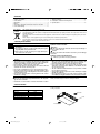
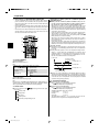
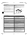
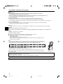
Air-Conditioners SEZ-KD25,KD35,KD50,KD60,KD71VAL OPERATION MANUAL FOR USER For safe and correct use, please read this operation manual thoroughly before operating the air-conditioner unit. BEDIENUNGSHANDBUCH English FÜR BENUTZER Zum sicheren und einwandfreien Gebrauch der Klimaanlage dieses Bedienungshandbuch vor Inbetriebnahme gründlich durchlesen. MANUEL D’UTILISATION Deutsch POUR L’UTILISATEUR Pour une utilisation correcte sans risques, veuillez lire le manuel d’utilisation en entier avant de vous servir du climatiseur. MANUAL DE INSTRUCCIONES Français PARA EL USUARIO Lea este manual de instrucciones hasta el final antes de poner en marcha la unidad de aire acondicionado para garantizar un uso seguro y correcto. ISTRUZIONI DI FUNZIONAMENTO Español PER L’UTENTE Leggere attentamente questi istruzioni di funzionamento prima di avviare l’unità, per un uso corretto e sicuro della stessa. BEDIENINGSHANDLEIDING Italiano VOOR DE GEBRUIKER Voor een veilig en juist gebruik moet u deze bedieningshandleiding grondig doorlezen voordat u de airconditioner gebruikt. DRIFTSMANUAL Nederlands FÖR ANVÄNDAREN Läs denna driftsmanual noga för säkert och korrekt bruk innan luftkonditioneringen används. Svenska DRIFTSMANUAL TIL BRUGER Læs venligst denne driftsmanual grundigt før airconditionanlægget betjenes af hensyn til sikker og korrekt brug. MANUAL DE OPERAÇÃO PARA O UTILIZADOR Para segurança e utilização correctas, leia atentamente o manual de operação antes de pôr a funcionar a unidade de ar condicionado. E°XEIPI¢IO O¢H°IøN XPH™Eø™ РУКОВОДСТВО ПО ЭКСПЛУАТАЦИИ Русский KULLANICI ‹Ç‹N Emniyetli ve do¤ru biçimde nas›l kullan›laca¤›n› ö¤renmek için lütfen klima cihaz›n› iflletmeden önce bu elkitab›n› dikkatle okuyunuz. 1 ∂ÏÏËÓÈο ДЛЯ ПОЛЬЗОВАТЕЛЯ Для обеспечения правильного и безопасного использования следует ознакомиться с инструкциями, указанными в данном руководстве по эксплуатации, тщательным образом до того, как приступать к использованию кондиционера. KB79H174H01_cover.pm6 Português °π∞ ∆√¡ Ã∏™∆∏ °È· ·ÛÊ¿ÏÂÈ· Î·È ÛˆÛÙ‹ ¯Ú‹ÛË, ·Ú·Î·Ï›ÛÙ ‰È·‚¿ÛÂÙ ÚÔÛ¯ÙÈο ·˘Ùfi ÙÔ ÂÁ¯ÂÈÚ›‰ÈÔ ¯Ú‹Ûˆ˜ ÚÈÓ ı¤ÛÂÙ Û ÏÂÈÙÔ˘ÚÁ›· ÙË ÌÔÓ¿‰· ÎÏÈÌ·ÙÈÛÌÔ‡. ‹fiLETME ELK‹TABI Dansk 07.7.10, 8:17 PM Türkçe Contents 1. Safety Precautions ................................................................ 2 2. Parts Names .......................................................................... 2 3. Operation ............................................................................... 4 4. Timer ..................................................................................... 5 5. Emergency Operation for Wireless Remote-controller .......... 5 6. Care and Cleaning ................................................................ 6 Note (Marking for WEEE) 7. Trouble Shooting .................................................................... 6 8. Installation, relocation and inspection ................................... 7 9. Specifications ........................................................................ 9 This symbol mark is for EU countries only. This symbol mark is according to the directive 2002/96/EC Article 10 Information for users and Annex IV. Your MITSUBISHI ELECTRIC product is designed and manufactured with high quality materials and components which can be recycled and reused. This symbol means that electrical and electronic equipment, at their end-of-life, should be disposed of separately from your household waste. Please, dispose of this equipment at your local community waste collection/recycling centre. In the European Union there are separate collection systems for used electrical and electronic product. Please, help us to conserve the environment we live in! 1. Safety Precautions s Before installing the unit, make sure you read all the “Safety Precautions”. s The “Safety Precautions” provide very important points regarding safety. Make sure you follow them. s Please report to or take consent by the supply authority before connection to the system. Symbols used in the text Warning: Describes precautions that should be observed to prevent danger of injury or death to the user. Caution: Describes precautions that should be observed to prevent damage to the unit. Symbols used in the illustrations : Indicates a part which must be grounded. Warning: • The unit must not be installed by the user. Ask the dealer or an authorized company to install the unit. If the unit is installed improperly, water leakage, electric shock or fire may result. • Do not stand on, or place any items on the unit. • Do not splash water over the unit and do not touch the unit with wet hands. An electric shock may result. • Do not spray combustible gas close to the unit. Fire may result. • Do not place a gas heater or any other open-flame appliance where it will be exposed to the air discharged from the unit. Incomplete combustion may result. • Do not remove the front panel or the fan guard from the outdoor unit when it is running. Caution: • Do not use any sharp object to push the buttons, as this may damage the remote controller. • Never block or cover the indoor or outdoor unit’s intakes or outlets. • When you notice exceptionally abnormal noise or vibration, stop operation, turn off the power switch, and contact your dealer. • Never insert fingers, sticks etc. into the intakes or outlets. • If you detect odd smells, stop using the unit, turn off the power switch and consult your dealer. Otherwise, a breakdown, electric shock or fire may result. • This air conditioner is NOT intended for use by children or infirm persons without supervision. • Young children must be supervised to ensure that they do not play with the air conditioner. • If the refrigeration gas blows out or leaks, stop the operation of the air conditioner, thoroughly ventilate the room, and contact your dealer. Disposing of the unit When you need to dispose of the unit, consult your dealer. 2. Parts Names ■ Indoor Unit ■ SEZ-KD·VAL Ceiling Concealed SEZ-KD·VAL Fan steps Vane Louver Filter Filter cleaning indication 3 steps – – Normal – Air intake Filter Air outlet 2 KB79H174H01_en.pm6 2 07.7.11, 9:13 AM 2. Parts Names ■ Wireless Remote-Controller SET TEMPERATURE button ON/OFF button SET TEMPERATURE button sets and any desired room temperature. CHECK TEST RUN MODEL SELECT Pushing button starts operation. Pushing again stops operation. NOT AVAILABLE FAN SPEED button This button is used to set fan speed to low, medium or high. Used for selecting timed starting or stopping. FAN AUTO STOP MODE SELECT button This button is used to change between auto, cooling, heating and drying operation modes. AUTO STOP/AUTO START button TEMP ON/OFF VANE CONTROL button MODE VANE AUTO START CHECK LOUVER Used to change the airflow direction. h CHECK button TEST RUN min h button Used for setting the current time. TEST RUN button SET RESET CLOCK min button Used for setting the current time. LOUVER button Used for adjusting the airflow direction. ■ When using the wireless remote controller, point it towards the receiver on the indoor unit. ■ If the remote controller is operated within approximately two minutes after power is supplied to the indoor unit, the indoor unit may beep twice as the unit is performing the initial automatic check. ■ The indoor unit beeps to confirm that the signal transmitted from the remote controller has been received. Signals can be received up to approximately 7 meters in a direct line from the indoor unit in an area 45° to the left and right of the unit. However, illumination such as fluorescent lights and strong light can affect the ability of the indoor unit to receive signals. ■ If the operation lamp near the receiver on the indoor unit is flashing, the unit needs to be inspected. Consult your dealer for service. ■ Handle the remote controller carefully! Do not drop the remote controller or subject it to strong shocks. In addition, do not get the remote controller wet or leave it in a location with high humidity. ■ To avoid misplacing the remote controller, install the holder included with the remote controller on a wall and be sure to always place the remote controller in the holder after use. Battery installation/replacement 1. Remove the top cover, insert two AAA batteries, and then install the top cover. 1 3 Top cover 2 Two AAA batteries Insert the negative (–) end of each battery first. Install the batteries in the correct directions (+, –)! 2. Press the Reset button. ■ Outdoor unit Power Press the Reset button with an object that has a narrow end. Ref. Pipes Indoor-Outdoor Connection wire Earth 3 KB79H174H01_en.pm6 3 07.7.11, 9:13 AM 3. Operation 3.1. Description of “AUTO RESTART FUNCTION” • This unit is equipped with the auto restart function. When the main power is turned on, the air conditioner will start operation automatically in the same mode as set with the remote controller before the shutoff of main power. • If the unit was set to off with the remote controller before the shutoff of main power, it will remain stopped even after the main power is turned on. • If the unit was in the TEST RUN before the shutoff of main power, it will start operation, at main power on, in the same mode as set with the remote controller before the TEST RUN. 3 5 2 6 TEMP ON/OFF 1 3 FAN AUTO STOP 2 5 MODE VANE AUTO START 6 CHECK LOUVER TEST RUN h min SET RESET CLOCK Information for multi system air conditioner (Outdoor unit: MXZ series) s Multi system air conditioner (Outdoor unit: MXZ series) can connect two or more indoor units with one outdoor unit. According to the capacity, two or more units can operate simultaneously. • When you try to operate two or more indoor units with one outdoor unit simultaneously, one for the cooling and the other for heating, the operation mode of the indoor unit that operates earlier is selected. The other indoor units that will start the operation later cannot operate, indicating an operation state in flashing. In this case, please set all the indoor units to the same operation mode. • There might be a case that the indoor unit, which is operating in (AUTO) mode. Cannot change over to the operating mode (COOL ↔ HEAT) and becomes a state of standby. • When indoor unit starts the operation while the defrosting of outdoor unit is being done, it takes a few minutes (max. about 15 minutes) to blow out the warm air. • In the heating operation, though indoor unit that does not operate may get warm or the sound of refrigerant flowing may be heard, they are not malfunction. The reason is that the refrigerant continuously flows into it. Automatic operation ■ According to a set temperature, cooling operation starts if the room temperature is too hot and heating operation starts if the room temperature is too cold. ■ During automatic operation, if the room temperature changes and remains 2 °C or more above the set temperature for 15 minutes, the air conditioner switches to cooling mode. In the same way, if the room temperature remains 2 °C or more below the set temperature for 15 minutes, the air conditioner switches to heating mode. Cooling mode 3.2. Turning ON/OFF 15 minutes (switches from heating to cooling) <To Start Operation> ■ Press the ON/OFF button 1. Set temperature +2°C Note: ● When the unit is restarted, initial settings are as follows. Mode Temperature setting Fan speed Remote Controller settings Last operation mode Last set temperature Last set fan speed COOL or DRY Mode HEAT FAN Set temperature Set temperature -2°C 15 minutes (switches from cooling to heating ) <To Stop Operation> ■ Press the ON/OFF button 1 again. ■ Because the room temperature is automatically adjusted in order to maintain a fixed effective temperature, cooling operation is performed a few degrees warmer and heating operation is performed a few degrees cooler than the set room temperature once the temperature is reached (automatic energy-saving operation). Note: Even if you press the ON/OFF button immediately after shutting down the operation is progress, the air conditioner will not start for about three minutes. This is to prevent the internal components from being damaged. s To decrease the room temperature: Press button 3 to set the desired temperature. The selected temperature is displayed 3. Airflow up/down 3.3. Mode select ■ Press the operation mode ( tion mode 2. s ) button 2 and select the opera- 3.4. Temperature setting s To increase the room temperature: Press button 3 to set the desired temperature. The selected temperature is displayed 3. • Available temperature ranges are as follows: Cooling/Drying: 19 - 30 °C Heating: 17 - 28 °C Automatic: 19 - 28 °C • The display flashes either 8 °C - 39 °C to inform you if the room temperature is lower or higher than the displayed temperature. Cooling mode Drying mode Fan mode Heating mode Automatic (cooling/heating) mode 4 KB79H174H01_en.pm6 4 07.7.11, 9:13 AM 3. Operation 3.5. Fan speed setting ■ Press the Fan Speed button 1 as many times as necessary while the system is running. • Each press changes the force. The currently selected speed is shown at A. • The change sequence, and the available settings, are as follows. A TEMP ON/OFF FAN AUTO STOP 1 Fan speed (Auto) 4-stage ( ) 3-stage ( ) 2-stage ( ) Remote controller display Low Middle 2 Middle 1 High (Middle) The wind speeds that can be selected depend on the model. Note that some units do not provide an “Auto” setting. The display and the fan speed of the unit will differ in the following situations: • When the unit is in STAND BY mode or in DEFROST mode. • Just after the heating mode (while waiting to change to another mode). • When the temperature of the room is higher than the temperature setting of the unit operating in the heating mode. • In the dry operation, the indoor fan automatically turns to low-speed operation. Switching of fan speed is impossible. MODE VANE AUTO START CHECK LOUVER 3.6. Ventillation h s For LOSSNAY combination TEST RUN min 3.6.1. For Wireless Remote-controller ● The ventillator will automatically operate when the indoor unit turns on. ● No indication on the wireless remote controller. SET RESET CLOCK 1 Press FAN button to select a desired fan speed. • Each time you press the button, available options change with the display A on the remote controller, as shown next. AAA AAA 4. Timer 4.1. For wireless remote controller C D B A TEMP ON/OFF FAN AUTO STOP MODE VANE AUTO START CHECK LOUVER TEST RUN 13 h min 2 SET RESET CLOCK 1) Set the current time 1 Press the CLOCK button using a thin stick and blink the time A. min 2 Press the h and button to set the current time. 3 Press the CLOCK button using a thin stick. 2) Set the time to start the unit as follows 1 Press the AUTO START button. • Time can be set while the following symbol is blinking. On time: B START is blinking. • The start times is displayed at A. min h 2 Use the and buttons to set the desired time. 3 To cancel the ON timer, press the AUTO START button. 3) Set the time to stop the unit as follows 1 Press the AUTO STOP button. • Time can be set while the following symbol is blinking. Off time: C STOP is blinking. • The stop times is displayed at D. min 2 Use the h and buttons to set the desired time. 3 To cancel the OFF timer, press the AUTO STOP button. 4) Changing the set times Press the AUTO START or AUTO STOP to cancel the timer and repeat from 2) or 3). AAA AAA 5. Emergency Operation for Wireless Remote-controller ON/OFF 1 2 HEAT 1 ON/OFF lamp (lit when unit is operating; unlit when unit is not operating) 2 Emergency operation In cases where the remote control unit does not operate properly, use either the COOL or HEAT button on the wireless remote control signal receiver to toggle the unit on or off. On cooler only units, pushing the HEAT button toggles the fan on and off. COOL Pressing the COOL or Operation mode Preset temperature Fan speed HEAT button selects the following settings. COOL 24 °C/75 °F High HEAT 24 °C/75 °F High 5 KB79H174H01_en.pm6 5 07.7.11, 9:13 AM 6. Care and Cleaning s Cleaning the filters • Clean the filters using a vacuum cleaner. If you do not have a vacuum cleaner, tap the filters against a solid object to knock off dirt and dust. • If the filters are especially dirty, wash them in lukewarm water. Take care to rinse off any detergent thoroughly and allow the filters to dry completely before putting them back into the unit. Caution: • Do not dry the filters in direct sunlight or by using a heat source, such as an electric heater: this may warp them. • Do not wash the filters in hot water (above 50°C), as this may warp them. • Make sure that the air filters are always installed. Operating the unit without air filters can cause malfunction. Caution: • Before you start cleaning, stop operation and turn OFF the power supply. • Indoor units are equipped with filters to remove the dust of sucked-in air. Clean the filters using the methods shown in the following sketches. s Filter removal Caution: • In removing the filter, precautions must be taken to protect your eyes from dust. Also, if you have to climb up on a stool to do the job, be careful not to fall. • When the filter is removed, do not touch the metallic parts inside the indoor unit, otherwise injury may result. ■ SEZ-KD·VAL A C B D D • While lifting the filter knob, pull it. A Air intake B Air outlet C Filter D Knob 7. Trouble Shooting Having trouble? Air conditioner does not heat or cool well. Here is the solution. (Unit is operating normally.) ■ Clean the filter. (Airflow is reduced when the filter is dirty or clogged.) ■ Check the temperature adjustment and adjust the set temperature. ■ Make sure that there is plenty of space around the outdoor unit. Is the indoor unit air intake or outlet blocked? ■ Has a door or window been left open? When heating operation starts, warm air does not blow from the indoor unit ■ Warm air does not blow until the indoor unit has sufficiently warmed up. soon. During heating mode, the air conditioner stops before the set room tem- ■ When the outdoor temperature is low and the humidity is high, frost may perature is reached. form on the outdoor unit. If this occurs, the outdoor unit performs a defrosting operation. Normal operation should begin after approximately 10 minutes. When the airflow direction is changed, the vanes always move up and down ■ When the airflow direction is changed, the vanes move to the set position past the set position before finally stopping at the position. after detecting the base position. A flowing water sound or occasional hissing sound is heard. ■ These sounds can be heard when refrigerant is flowing in the air conditioner or when the refrigerant flow is changing. A cracking or creaking sound is heard. ■ These sounds can be heard when parts rub against each due to expansion and contraction from temperature changes. The room has an unpleasant odor. ■ The indoor unit draws in air that contains gases produced from the walls, carpeting, and furniture as well as odors trapped in clothing, and then blows this air back into the room. A white mist or vapor is emitted from the indoor unit. ■ If the indoor temperature and the humidity are high, this condition may occur when operation starts. ■ During defrosting mode, cool airflow may blow down and appear like a mist. Water or vapor is emitted from the outdoor unit. ■ During cooling mode, water may form and drip from the cool pipes and joints. ■ During heating mode, water may form and drip from the heat exchanger. ■ During defrosting mode, water on the heat exchanger evaporates and water vapor may be emitted. The operation indicator does not appear in the remote controller display. ■ Turn on the power switch. “ ” will appear in the remote controller display. “ ” appears in the remote controller display. ■ During central control, “ ” appears in the remote controller display and air conditioner operation cannot be started or stopped using the remote controller. When restarting the air conditioner soon after stopping it, it does not oper- ■ Wait approximately three minutes. ate even though the ON/OFF button is pressed. (Operation has stopped to protect the air conditioner.) Air conditioner operates without the ON/OFF button being pressed. ■ Is the on timer set? Press the ON/OFF button to stop operation. ■ Is the air conditioner connected to a central remote controller? Consult the concerned people who control the air conditioner. ■ Does “ ” appear in the remote controller display? Consult the concerned people who control the air conditioner. ■ Has the auto recovery feature from power failures been set? Press the ON/OFF button to stop operation. 6 KB79H174H01_en.pm6 6 07.7.11, 9:14 AM 7. Trouble Shooting Having trouble? Air conditioner stops without the ON/OFF button being pressed. Remote controller timer operation cannot be set. “PLEASE WAIT” appears in the remote controller display. An error code appears in the remote controller display. Draining water or motor rotation sound is heard. Noise is louder than specifications. Here is the solution. (Unit is operating normally.) ■ Is the off timer set? Press the ON/OFF button to restart operation. ■ Is the air conditioner connected to a central remote controller? Consult the concerned people who control the air conditioner. ■ Does “ ” appear in the remote controller display? Consult the concerned people who control the air conditioner. ■ Are timer settings invalid? If the timer can be set, WEEKLY , SIMPLE , or AUTO OFF appears in the remote controller display. ■ The initial settings are being performed. Wait approximately 3 minutes. ■ The protection devices have operated to protect the air conditioner. ■ Do not attempt to repair this equipment by yourself. Turn off the power switch immediately and consult your dealer. Be sure to provide the dealer with the model name and information that appeared in the remote controller display. ■ When cooling operation stops, the drain pump operates and then stops. Wait approximately 3 minutes. ■ The indoor operation sound level is affected by the acoustics of the particular room as shown in the following table and will be higher than the noise specification, which was measured in an echo-free room. High soundLow soundNormal rooms absorbing rooms absorbing rooms Broadcasting Location Reception room, Office, hotel studio, music examples hotel lobby, etc. room room, etc. 3 to 7 dB Noise levels 6 to 10 dB 9 to 13 dB Nothing appears in the wireless remote controller display, the display is ■ The batteries are low. faint, or signals are not received by the indoor unit unless the remote conReplace the batteries and press the Reset button. troller is close. ■ If nothing appears even after the batteries are replaced, make sure that the batteries are installed in the correct directions (+, –). The operation lamp near the receiver for the wireless remote controller on ■ The self diagnosis function has operated to protect the air conditioner. the indoor unit is flashing. ■ Do not attempt to repair this equipment by yourself. Turn off the power switch immediately and consult your dealer. Be sure to provide the dealer with the model name. 8. Installation, relocation and inspection Installation place Avoid installing the air conditioner in the following places. • Where flammable gas could leak. Caution: Do not install the unit where flammable gas could leak. If gas leaks and collects around the unit, it may cause an explosion. • • • • Where there is much machine oil. Salty place such as the seaside. Where sulfide gas is generated such as a hot spring. Where there is oil splashing or much oily smoke. Inverter type fluorescent lamp Wall, etc. To prevent the effect of a fluorescent lamp, keep it away as far apart as possible. To prevent picture distortion or noise, keep 1 m or more apart. Wellventilated dry place 100 mm or more 400 mm or more TV Warning: If the air conditioner operates but does not cool or heat (depending on model) the room, consult your dealer since there may be a refrigerant leak. Be sure to ask the service representative whether there is refrigerant leakage or not when repairs are carried out. The refrigerant charged in the air conditioner is safe. Refrigerant normally does not leak, however, if refrigerant gas leaks indoors, and comes into contact with the fire of a fan heater, space heater, stove, etc., harmful substances will be generated. Radio Electrical work • Provide an exclusive circuit for power supply of the air conditioner. • Be sure to observe the breaker capacity. Warning: • The customer should not install this unit. If the unit is installed incorrectly, fire, electric shock, injury due to a falling unit, water leakage, etc. may result. • Do not connect using branched outlet or an extension cord, and do not attach many loads to one electric outlet. A fire or electric shock may result from poor contact, poor insulation, exceeding the permissible current, etc. Consult your dealer. 7 KB79H174H01_en.pm6 7 07.7.11, 9:14 AM 8. Installation, relocation and inspection Caution: • Apply grounding Do not connect a grounding wire to a gas pipe, water pipe, lightning rod or ground wire of a telephone. If a grounding is incorrect, it may cause an electric shock. • Install an earth leakage breaker depending on the place where the air conditioner is to be installed (humid place, etc.). If the earth leakage breaker is not installed, it may cause an electric shock. Inspection and maintenance • When the air conditioner is used for several seasons, the capacity may be lowered due to dirt inside the unit. • Depending upon the conditions of use, an odor may be generated or dirt, dust, etc. may prevent proper drainage. • It is recommended to apply inspection and maintenance (charged) by a specialist in addition to normal maintenance. Consult your dealer. Also consider operation sound • Do not put an object around the air outlet of the outdoor unit. It may cause lowering of capacity or increase operating sound. • If abnormal sound is heard during operation, consult your dealer. Relocation • When the air conditioner is to be removed or reinstalled because of rebuilding, moving, etc., special techniques and work are required. Warning: Repair or relocation should not be done by the customer. If this is done incorrectly, it may cause a fire, electric shock, injury by dropping of the unit, water leakage, etc. Consult your dealer. Disposal • To dispose of this product, consult your dealer. <Installation for Remote-Controller> ■ Use the remote controller holder that is provided to avoid misplacing the remote controller. ■ Install the remote controller in a location that meets the following conditions. • Out of the direct sun light • Away from any heat sources • Out of the airflow from the air conditioner (cool or warm) • Where the operation of the remote controller can easily be performed and the display is readily visible to the user • Out of the reach of small children NOTES: * If there is a fluorescent light in the room in which the air conditioner is to be installed, turn it on and make sure that the signal from the remote controller can be received by the indoor unit from the intended installation location. When the signal receiving unit receives a signal from the remote controller, a short beeping sound will be heard. If the air conditioner unit is installed in a room in which a fluorescent light on an electronic lighting control system (i.e., inverter light) is installed, signal interference may occur. * Maximum signal receiving distance is approximately 7 meters (Approx. 22 feet). Signal receiving angle is approximately 45 degrees to the right and the left from the center. * Install the unit at least 1 meter (Approx. 3 feet) away from the TV or radio. (If the unit is installed too close to these appliances, signal interference (picture distortion and noise) may occur.) ■ Use the tapping screws that are provided to mount the remote controller holder on the wall, and then place the remote controller in the holder. NOTES: <Functions not supported by older versions of signal receiving unit > • Temperature setting in 1 °F increments. • Control operations that are performed on the controller with the setting other than “Standard 2 °F”. If you have any question, consult your dealer. 8 KB79H174H01_en.pm6 8 07.7.11, 9:14 AM 9. Specifications Model Function Power supply Capacity Input Indoor unit Airflow (Lo-Mid-Hi) Ext. static pressure Noise level (Lo-Mid-Hi) Weight Outdoor unit Noise level Refrigerant R410A Weight Notes: 1. 2. 3. 4. kW BTU/h kW CMM Pa dB kg dB kg kg SEZ-KD25VAL Cooling Heating SEZ-KD35VAL Cooling Heating 2.5 3.0 8,500 10,200 0.04 0.04 SEZ-KD25VAL 5.5-7-9 5/15/35/50 23-26-30 18 SUZ-KA25VA 46 0.90 33 3.5 4.0 11,900 13,600 0.05 0.05 SEZ-KD35VAL 7-9-11 5/15/35/50 23-28-33 21 SUZ-KA35VA 48 1.05 35 SEZ-KD50VAL Cooling Heating ~/N, 230V, 50Hz 5.0 5.9 17,100 20,100 0.07 0.07 SEZ-KD50VAL 10-12.5-15 5/15/35/50 30-34-37 23 SUZ-KA50VA 55 1.6 53 SEZ-KD60VAL Cooling Heating SEZ-KD71VAL Cooling Heating 5.5 6.9 18,800 23,500 0.07 0.07 SEZ-KD60VAL 12-15-18 5/15/35/50 30-34-38 27 SUZ-KA60VA 55 1.8 53 7.1 8.1 24,200 27,600 0.10 0.10 SEZ-KD71VAL 12-16-20 5/15/35/50 30-35-40 27 SUZ-KA71VA 55 2.0 58 Rating conditions (cooling) Indoor : 27°C DB, 19°C WB Outdoor : 35°C DB Rating conditions (heating) Indoor : 20°C DB Outdoor : 7°C DB, 6°C WB Specifications subject to change without notice. The external static pressure is set to 15 Pa at factory shipment. Guaranteed operating range Indoor Cooling Heating Upper limit Lower limit Upper limit Lower limit 32°C DB, 23°C WB 21°C DB, 15°C WB 27°C DB, – 20°C DB, – Outdoor KD25, KD35 KD50, KD60, KD71 46°C DB, – 43°C DB, – -10°C DB, – 24°C DB, 18°C WB -10°C DB, -11°C WB Units should be installed by licensed electric contractor accordingly to local code requirement. 9 KB79H174H01_en.pm6 9 07.7.11, 9:14 AM This product is designed and intended for use in the residential, commercial and light-industrial environment. The product at hand is based on the following EU regulations: • • Low Voltage Directive 2006/95/ EC Electromagnetic Compatibility Directive 89/ 336/ EEC, 2004/108/ EC Please be sure to put the contact address/telephone number on this manual before handing it to the customer. HEAD OFFICE: TOKYO BLDG., 2-7-3, MARUNOUCHI, CHIYODA-KU, TOKYO 100-8310, JAPAN KB79H174H01 KB79H174H01_cover.pm6 4 07.7.10, 8:17 PM