1
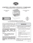
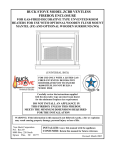
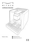
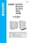
U
STATESSTOVE
TED
NI
USSC
COMPANY
United States
Stove Company
Vent-Free Zero-Clearance Gas Fireplace
Models VFZC32N, VFZC32L
Shown with optional
cabinet mantel, hearth
base, and brass trim.
OWNER'S OPERATION AND INSTALLATION MANUAL
This firebox may be installed in an aftermarket* manufactured (mobile) home,
where not prohibited by state or local codes.
* Aftermarket: Completion of sale, not for purpose of resale, from the manufacturer
(i.e. Installation of this product is permitted after the manufactured (mobile) home is sited).
This is an unvented gas-fired
heater. It uses air (oxygen) from
the room in which it is installed.
Provisions
for
adequate
combustion and ventilation air
must be provided. Refer to
"Adequate Combustion And
Ventilation Air" on pages 6-10 of
this manual.
WARNING:
Do not use a blower insert,
heat exchanger insert or other
accessories not approved
for use with this heater.
Save this manual for
future reference.
WARNING: If the information in this manual is
not followed exactly, a fire or explosion may
result causing property damage, personal injury,
or loss of life.
~Do not store or use gasoline or other flammable
vapors and liquids in the vicinity of this or any
other appliance.
~WHAT TO DO IF YOU SMELL GAS
* Do not try to light any appliance
* Do not touch any electrical switch; do not
use any phone in your building
* Immediately call your gas supplier from a
neighbor's phone. Follow the gas supplier's
instructions
* If you cannot reach your gas supplier, call
the fire department
~Installation and service must be performed by
a qualified installer, service agency, or the gas
supplier.
851301 3/98
TABLE OF CONTENTS
SECTION
PAGE
LOCAL CODES.......................................................................................................2
WARNINGS/SAFETY INFORMATION.................................................................2-4
VFZC32 SPECIFICATIONS.................................................................................4-5
PRODUCT FEATURES...........................................................................................6
LOCATING THE FIREPLACE.....................................................................................6
AIR FOR COMBUSTION AND VENTILATION..................................................6-10
INSTALLATION................................................................................................10-13
GAS CONNECTION........................................................................................14-15
GAS PRESSURE CHECK.....................................................................................15
MANTEL INSTALLATION................................................................................16-18
BUILT-IN INSTALLATION.................................................................................18-19
LOG ASSEMBLY...................................................................................................20
OPERATING INSTRUCTIONS........................................................................21-23
CLEANING/SERVICING..................................................................................23-24
FLAME APPEARANCE.........................................................................................24
PARTS DIAGRAM & LIST.....................................................................................25
GENERATOR ASSEMBLY PARTS DIAGRAM......................................................26
GENERATOR ASSEMBLY PARTS LIST................................................................27
VF32B BLOWER KIT WIRING DIAGRAM............................................................28
OPTIONAL ACCESSORIES.............................................................................29-30
HOW TO ORDER REPAIR PARTS........................................................................31
LOCAL CODES
Install and use fireplace with care. Follow all local codes. In the absence of local codes, use
the latest edition of The National Fuel Gas Code ANSI Z223.1, also known as NFPA 54*.
Firebox must be electrically grounded in accordance with the National Electric Code, ANSI/
NFPA 70 (latest edition).
*Available from:
American National Standards Institute, Inc.
1430 Broadway
New York, NY 10018
National Fire Protection Association, Inc.
Batterymarch Park
Quincy, MA 02269
WARNINGS/SAFETY INFORMATION
IMPORTANT: Read this owner's manual carefully and completely before trying to
assemble, operate, or service this fireplace. Improper use of this fireplace can cause
serious injury or death from burns, fire, explosion, electrical shock, and carbon poisoning.
2
WARNINGS/SAFETY INFORMATION CONTINUED
WARNING: Any change to this heater or its controls can be dangerous.
1. This heater shall not be installed in a bedroom or bathroom.
2. Never install the fireplace
* in a recreational vehicle
* where curtains, furniture, clothing, or other flammable objects are less than
36 inches from the front, top, or side of the fireplace
* in high traffic areas
* in windy or drafty areas
3. Do not add extra logs or ornaments such as pine cones, vermiculite, or rock wool.
Using these added items can cause sooting.
4. You must operate this fireplace with the fireplace screen and hood in place.
Make sure these parts are in place before running.
5. Do not allow fans to blow directly into the firebox. Avoid any drafts that alter burner flame
patterns. Ceiling fans can create drafts that alter burner flame patterns. Altered burner
patterns can cause sooting.
6. To prevent malfunction and/or sooting, an unvented gas heater should be cleaned at
least annually by a professional service person. More frequent cleaning may be required
due to excessive lint from carpeting, etc. It is imperative that control compartments,
burners and circulating air passageways be kept clean.
7. Correct placement of the ceramic fiber logs is necessary to avoid problems with sooting.
Sooting can settle on surfaces outside the heater and cause discoloration. See the
appropriate section of this manual for instructions.
8. This Vent-free gas log heater requires fresh air ventilation to run properly. See Air for
Combustion and Ventilation instructions in this owner's manual.
9. Do not run fireplace
* where flammable liquids or vapors are used or stored
* under dusty conditions
10. Do not use this fireplace to cook food or burn paper or other objects.
11. Never place any objects in the firebox or on logs.
12. Fireplace front and screen becomes very hot when running. Keep children and adults
away from hot surfaces to avoid burns or clothing ignition. Firebox will remain hot for a
time after shutdown. Allow surfaces to cool before touching.
13. Carefully supervise young children when they are in the room with fireplace.
14. Turn fireplace off and let cool before servicing. Only a qualified service person should
service and repair fireplace.
15. Operating vent-free gas log heaters in a fireplace above elevations of 4,500 feet could
cause pilot outage.
16. IMPORTANT: The fireplace hood must not be replaced with a hood/canopy which may
be provided with the decorative type unvented room heater.
3
WARNINGS/SAFETY INFORMATION CONTINUED
17. CARBON MONOXIDE POISONING: Early signs of carbon monoxide poisoning are
similar to the flu with headaches, dizziness and/or nausea. If you have these signs,
obtain fresh air immediately. Have the heater serviced as it may not be operating
properly.
18. This vent-free gas fireplace is intended to be smokeless. If logs appear to smoke, turn off
the heater and call a qualified service person. Initial burn off may cause slight smoke and
odor during the first four hours of operation.
19. Input ratings are shown in BTU per hour and are for elevations up to 2,000 feet. For
elevations above 2,000 feet, input ratings should be reduced 4 percent for each 1,000
feet above see level. Refer to the National Fuel Gas Code.
20. The fireplace and its individual shut off valve must be disconnected from the gas supply
piping system during any pressure testing of that system at test pressures in excess of
1/2 psig (3.5 kPa).
21. The fireplace must be isolated from the gas supply piping system be closing its individual
manual shutoff valve during any pressure testing of the gas supply piping system at
test pressures equal to or less than 1/2 psig (3.5 kPa).
22. Do not use this gas fireplace if any part has been under water. Immediately call a
qualified service technician to inspect the room heater and to replace any part of the
control system and any gas control which has been under water.
VFZC32 SPECIFICATIONS
Natural Gas
Propane/LPG
Manifold Pressure Setting:
Gas Inlet Pressure:
Maximum
Minimum
Model Number
VFZC32N
VFZC32L
4" w.c.
10-1/2" w.c.
5" w.c.
Type
Manual
Manual
Manifold Pressure Setting:
Gas Inlet Pressure:
Maximum
Minimum
Gas Rate
Max BTU/Hr
Min BTU/Hr
30,000
30,000
8,000
8,000
10" w.c.
13" w.c.
11" w.c.
Number
of Burners
2
2
Controls - Main control has 4 positions:
1.
2.
3.
4.
OFF - All gas to the gas logs is shut off at the control
IGN - Piezo ignitor allows ignition of the pilot without the use of matches or batteries
PILOT - Valve position to light/maintain a standing pilot
ON - Gas flow to complete system, front burner ignition
Front Burner Control Knob - infinite control, rotate clockwise to minimum rate and counterclockwise
to maximum rate.
Rear Burner Control Knob - Has 3 positions:
1. OFF - Gas to rear burner is shutoff at control
2. ON/MAX - Maximum gas flow to rear burner
3. MIN - Minimum gas flow rate to rear burner
4
VFZC32 SPECIFICATIONS, CONTINUED...
FIREBOX TOP VIEW
FIREBOX FRONT VIEW
FIREBOX SIDE VIEW
5
PRODUCT FEATURES
Operation
This Vent-free Gas Fireplace requires no outside venting or chimney making installation easy
and inexpensive. When used without the optional blower (model VF32B), the firebox
requires no electricity making it ideal for emergency backup heat.
Blower Accessory
The VFZC32 Vent-free Gas Fireplace will accept the VF32B Blower Kit accessory. The kit
comes with the variable blower. The variable blower allows you to select the fan speed you
desire. The blower circulates heated air from the firebox into the room. Use of the blower is
optional.
LOCATING FIREPLACE
Planning
Plan where you will install the fireplace. This will save time and money later when you install
the fireplace. Before installation, consider the following:
1. Where the fireplace will be located. Allow for wall and ceiling clearances (see
Installation Clearances, pages 10 & 11).
2. Everything needed to complete installation.
3. These models CANNOT be installed in a bedroom or bathroom.
4. Proper air for combustion and ventilation (see below).
AIR FOR COMBUSTION AND VENTILATION
WARNING
This fireplace shall not be installed in a confined space unless provisions are
provided for adequate combustion and ventilation air. Read the following
instructions to insure proper fresh air for this and other fuel-burning appliances in
your home.
Today's homes are built more energy efficient than ever. New materials, increased insulation, and new construction methods help reduce heat loss in homes. Home owners weather
strip and caulk around windows and doors to keep the cold air out and the warm air in. During
heating months, home owners want their homes as airtight as possible.
While it is good to make your home energy efficient, your home needs to breathe. Fresh air
must enter your home. All fuel-burning appliances need fresh air for proper combustion and
ventilation.
Exhaust fans, fireboxes, clothes dryers, and fuel-burning appliances draw air from the house
to operate. You must provide adequate fresh air for these appliances. This will insure proper
6 venting of vented fuel-burning appliances.
AIR FOR COMBUSTION AND VENTILATION CONTINUED
Providing adequate ventilation
The following is excerpts from National Fuel Gas Code. NFPA 54/ANSI Z223.1, Section 5.3,
Air for Combustion and Ventilation.
All spaces in homes fall into one of the three following ventilation classifications:
1. Unusually Tight Construction; 2. Unconfined Space; 3. Confined Space.
The information on pages 6 through 10 will help you classify your space and provide adequate ventilation.
Unusually Tight Construction
The air that leaks around doors and windows may provide enough fresh air for combustion
and ventilation. However, in buildings of unusually tight construction, you must provide
additional fresh air.
Unusually tight construction is defined as construction where:
a. Walls and ceilings exposed to the outside atmosphere have a continuous
water vapor retarder with a rating of one perm (6x10-11 per pa-sec-m 2 ) or less
with openings gasketed or sealed and
b. Weather stripping has been added on openable windows and doors and
c. Caulking or sealants are applied to areas such as joints around window and
door frames, between sole plates and floors, between wall-ceiling joints,
between wall panels, at penetrations for plumbing, electrical, and gas lines,
and at other openings.
If your home meets all of the three criteria above, you must provide additional fresh air. See
Ventilation Air From Outdoors, page 10.
If your home does not meet all of the three criteria above, proceed to page 8.
Confined Space and Unconfined Space
The National Fuel Gas Code (ANSI Z223.1, 1992 Section 5.3) defines a confined space as a
space whose volume is less than 50 cubic feet per 1,000 BTU per hour (4.8m3 per kw) of the
aggregate input rating of all appliances installed in that space and an unconfined space as a
space whose volume is not less than 50 cubic feet per 1,000 BTU per hour (4.8m3 per kw) of
the aggregate input rating of all appliances installed in that space. Rooms communicating
directly with the space in which the appliances are installed*, through openings not furnished
with doors, are considered a part of the unconfined space.
* Adjoining rooms are communicating only if there are doorless passageways or ventilation
grills between them.
7
AIR FOR COMBUSTION AND VENTILATION CONTINUED
Determining if You Have a Confined or Unconfined Space
Use this worksheet to determine if you have a confined or unconfined space.
Space: Includes the room in which you will install the firebox plus any adjoining rooms with
doorless passageways or ventilation grills between the rooms.
1.
2.
3.
Determine the volume of the space (length x width x height).
Length x Width x Height = _______________ cu. Ft. (volume of space)
Example: Space size
22 ft. (length) x 18 ft. (width) x 8 ft. (ceiling height) =
3168 cu. Ft. (volume of space)
If additional ventilation to adjoining room is supplied with grills or openings, add the
volume of these rooms to the total volume of the space.
Divide the space volume by 50 cubic feet to determine the maximum BTU/Hr the space
can support.
_________ (volume of space) 50 cu. Ft. = (Maximum BTU/Hr the space can support)
Example: 3168 cu. Ft. (volume of space) 50 cu. Ft. = 63.3 or 63,300 (maximum
BTU/Hr the space can support)
Add the BTU/Hr of all fuel-burning appliances in the space.
Vent-free Firebox
Gas water heater*
Gas furnace
Vented gas heater
Gas firebox logs
Other gas appliances*
Total
__________________
__________________
__________________
__________________
__________________
+ __________________
= __________________
BTU/Hr
BTU/Hr
BTU/Hr
BTU/Hr
BTU/Hr
BTU/Hr
BTU/Hr
Example: Gas water Heater
40,000
BTU/Hr
Vent-free firebox with log heater
+
39,000
BTU/Hr
Total
=
79,000
BTU/Hr
* Do not include direct-vent gas appliances. Direct-vent draws combustion air from
the outdoors and vents to the outdoors.
4. Compare the maximum BTU/Hr the space can support with the actual amount of
BTU/ Hr used.
______________ BTU/Hr (maximum the space can support)
______________ BTU/Hr (actual amount of BTU/Hr used)
Example: 63,300 BTU/Hr (maximum the space can support)
79,000 BTU/Hr (actual amount of BTU/Hr used)
The space in the above example is a confined space because the actual BTU/Hr used is
more than the maximum BTU/Hr the space can support. You must provide additional fresh
air.
Your options are as follows:
A. Rework worksheet, adding the space of an adjoining room. If the extra space provides
an unconfined space, remove door to adjoining room or add ventilation grills between
rooms. See Ventilation Air From Inside Building, page 9.
8
AIR FOR COMBUSTION AND VENTILATION CONTINUED
B.
C.
Vent room directly to the outdoors. See Ventilation Air from Outdoors, page 10.
Install a lower BTU/Hr firebox, if lower BTU/Hr size makes room unconfined.
If the actual BTU/Hr used is less than the maximum BTU/Hr the space can support, the space
is an unconfined space. You will need no additional fresh air ventilation.
WARNING
If the area in which the firebox and gas log heater may be operated is smaller than
that defined as an unconfined space, provide adequate combustion and
ventilation air by one of the methods described in the National Fuel Gas Code,
ANSI Z223.1, 1992, Section 5.3.
VENTILATION AIR
Ventilation Air From Inside Building
This fresh air would come from an adjoining unconfined space. When ventilating to an adjoining unconfined space, you must provide two permanent openings: one within 12" of the
ceiling and one within 12" of the floor into adjoining room ( see options in Figure 1).
Follow the National Fuel Gas Code NFPA 54/ ANSI Z223.1, Section 5.3, Air for Combustion
and Ventilation for required size of ventilation grills or ducts.
WARNING
Rework worksheet, adding the space of the adjoining unconfined space. The
combined spaces must have enough fresh air to supply all appliances in both
spaces.
Figure 1 - Ventilation Air from Inside Building
9
AIR FOR COMBUSTION AND VENTILATION CONTINUED
Ventilation Air From Outdoors
Provide extra fresh air by using ventilation grills or ducts. You must provide two permanent
openings: one within 12" of the ceiling and one within 12" of the floor. Connect these items
directly to the outdoors or spaces open to the outdoors. These spaces include attics and
crawl spaces. (See Figure 2)
IMPORTANT: Do not provide openings for inlet or outlet air into attic if attic has a thermostatcontrolled power vent. Heated air entering the attic will activate the power vent.
Figure 2 - Ventilation Air from Outdoors
INSTALLATION
INSTALLATION CLEARANCES
WARNING
Maintain the minimum clearances. If you can, provide greater clearances from
floor, ceiling, and adjoining wall.
Carefully follow the instructions below. This will ensure safe installation.
Minimum Wall and Ceiling Clearances (see Figure 3)
A. Clearances from the side of the firebox opening to any combustible wall should not
be less than 6 inches. (This applies to built-in installation or using an (optional) cabinet
mantel kit.)
B. Clearances from the top of the firebox opening to the ceiling should not be less than
42 inches.
Mantel Clearances for Conventional Installation
10
INSTALLATION CONTINUED
NOTE: CLEARANCES ARE THE
SAME IF USING OPTIONAL
CABINET MANTELS OR BUILT-IN
INSTALLATION.
42"
6" TO
SIDE WALL
Figure 3 - Minimum Clearance to Wall and Ceiling
Mantel Clearances for Built-in Installation
If placing custom mantel above built-in fireplace, you must meet minimum clearance
between mantel shelf and top of fireplace opening.
WALL
MANTEL SHELF
UNDERSIDE OF
MANTEL SHELF
MANTEL
WIDTH
DISTANCE TO
UNDERSIDE OF
MANTEL
If your installation does not meet the
above minimum clearances, you must:
* raise the mantel to an
acceptable height, OR
* remove the mantel.
TOP OF
FIREPLACE
OPENING
ALL MINIMUM
DISTANCES ARE
IN INCHES
Figure 4 - Minimum Mantel
Clearances for Built-in Installation
SIDE VIEW OF FIREBOX
11
INSTALLATION CONTINUED
Installing the Fireplace Screen.
1.
2.
3.
Insert each rod through the rings located at the top of the screen. NOTE: Before placing
the last ring over the rod, slide the tinnerman clip (included in the parts bag) onto the rod
and then slide the last ring over the rod. (See Figure 5)
Insert the right screen and rod into the hole in the side trim and line up rod with the back
hole in the firebox top and fasten with one of the 5/16" head screws included.
Now insert the left screen and rod as above. (Figure 5)
HOLE FOR ROD
TINNERMAN
CLIP
SCREW
ROD
RING
SCREEN
Figure 5 - Installing Fireplace Screen
Installing the Fireplace Hood.
1.
Slide the Hood over the shoulder screws and gentle press down until secure. NOTE:
There are (2) shoulder screws on each side of the firebox opening directly below the
top plate. These shoulder screws should line up with the notches on the sides of the
Fireplace Hood. (See Figure 6)
SHOULDER SCREW
HOOD CUT-AWAY
TO SHOW
UNDERSIDE
12
Figure 6 - Installing the Fireplace Hood.
INSTALLATION CONTINUED
Installing the Firebrick Panels into the firebox.
1.
2.
3.
4.
5.
6.
Before installing the firebrick panels you must first remove the brick brackets.
A 5/16" nut driver will be required. (See Figure 7a & b, below for location)
Carefully remove the firebrick panels from their box.
Decide which side of the firebox you want the gas line to enter and knock out the
appropriate holes in the cabinet, firebox, and the firebrick panel.
Place the back firebrick panel in the firebox, as shown in Figure 7a.
Place the side firebrick panels in the firebox, as shown in Figure 7b.
You can now replace the brick brackets using a 5/16" nut driver.
ATTACH BRACKET W/SCREW
BRICK BRACKET
BACK FIREBRICK PANEL
Figure 7a
ATTACH BRACKET W/SCREW
SIDE FIREBRICK PANEL
Figure 7b
Firebox shown with some parts missing for clarity.
13
CAUTION
NOTICE
GAS CONNECTION
A qualified gas appliance installer must connect the fireplace to
the gas supply. Consult all local codes.
Use new black iron or steel pipe only. Internally tinned copper tubing can be
used in some areas when permitted by local codes. Only use pipe of 1/2" or
greater diameter to allow full gas volume to heater. Excessive pressure loss will
occur if the pipe is too small.
A manual shutoff valve, union and plugged 1/8" NPT pressure tapping point
must be installed upstream of the heater (FIGURE 8).
A sediment trap must be installed upstream of the heater to prevent moisture
and contaminants from passing through the pipe to the heater controls and
burners. Failure to do so could prevent the heater from operating reliably
(FIGURE 8).
TO HEATER
CONTROL VALVE
IMPORTANT: Loosen the pipe adapter
on the flex tube before installing to the
system piping.
STAINLESS
FLEXIBLE TUBE
PIPE
MANUAL
SHUTOFF VALVE
PIPE
COUPLING
TEE JOINT
SEDIMENT TRAP
FIGURE 8. Gas Connection
PIPE NIPPLE
CAP
WARNING
CHECK GAS TYPE: The gas supply must be the same as stated on heater's rating plate. If the
gas supply is different, DO NOT INSTALL the heater. Contact your dealer for the correct model.
14
Connecting directly to an unregulated propane/LPG tank can
cause an explosion.
GAS CONNECTION, CONTINUED...
The gas inlet connection is 3/8" NPT, made at the rear of the main control. This unit comes with
an 18" gas flex pipe attached to the control valve at the factory. Run gas line into firebox from
either side and attach to gas flex pipe.
Test all gas joints from the gas meter to the heater for leaks using soap and water solution after
completing connection. DO NOT USE AN OPEN FLAME.
Note: Gas Flex pipe can be
ran to either side of the
fireplace for ease of gas
connection.
Gas Flex Pipe
FIGURE 9. Flex Pipe Connected to control
GAS PRESSURE CHECK
The heater regulator controls the burner pressure which should be checked at the pressure test
point located on the right side of the main control and is accessible from the side of the gas log
assembly (see FIGURE 10).
The pressure should be checked with the heater burning and the control set to high (HI).
The pressure regulator is preset and locked to avoid tampering. If the pressure is not as
specified in Product Specifications (Page 2), contact your dealer and replace the regulator.
Control Bracket
(Rightside view
facing heater)
Test Pressure
Input
Test Pressure
Output
Control Valve
FIGURE 10 -
Pressure Test Point Location
15
MANTEL INSTALLATION
Fireplace Installation Using Optional Mantel.
This fireplace may be installed using the cabinet mantel with hearth base accessory against
a wall in your home. You must use one of the Satin Black or Polished BrassTrim Kits
available when installing your fireplace with the optional mantel kit. (See Accessories on
page 28 & 29). NOTE: The Trim Kits provide a finished appearance covering rough and/or
unfinished mantel edges.
NOTE: The instructions below show installation using the VFGO32M/VFUF32M series
cabinet mantels and the VFGO32B/VFUF32B series hearth base accessories. The hearth
base accessory shown is optional for this installation. You can install the fireplace and mantel
directly on the floor. The VFUN32FM face mantel accessories cannot be installed with the
VFGO32B/VFUN32B series hearth base. You must install the face mantels directly on the
floor.
NOTE: If using the VFUF32FM series face mantel accessory, a wall recess opening will be
needed. See installation instructions for VFUF32FM series face mantel accessory.
1.
2.
3.
Assemble cabinet mantel, hearth base (optional), and trim accessories.
Assembly instructions are included with each accessory.
If using an optional VF32B blower, install a properly grounded, 120 volt three-prong
electrical outlet at firebox location if an outlet is not there. If possible, locate outlet so
cabinet mantel will cover it when installed (see Figure 11, below).
Install gas piping to fireplace location. For this installation you will need an approved
flexible gas line (if allowed by local codes) and a manual shutoff valve. The flexible gas
line must be the last item installed on the gas piping. See Connecting to Gas Supply
on pages 14 & 15.
NOTICE
A qualified service person must connect fireplace to gas supply. Follow all local
codes.
4.
Place (optional) hearth base accessory against wall at installation location. Cut an
access hole in hearth top to run flexible gas line to fireplace (see Figure 11). Make sure
to locate access hole so cabinet mantel will cover it when installed. Note: you can secure
base to floor using wood screws. Countersink screw heads and putty over.
Flexible Gas Line
Hearth Base
Electrical Outlet
Gas Line
Access Hole
16
Figure 11 - Placing (optional) Hearth Base against wall
MANTEL INSTALLATION CONTINUED
5.
Center the unit on the Hearth Base. Run the Gas Line into the firebox. You can access
beneath the firebox, to connect gas supply to control valve, from the left or right of the
unit. Knock out the appropriate holes and run the flexible gas line into the fireplace and
connect to the flexible gas line supplied with the fireplace.
6.
If installing Optional VF32B
Blower Kit, use a standard
3-prong power supply cord
(not included) and plug
blower into outlet.
NOTE: See Blower
Kit Instruction sheet
for full installation
instructions.
Knock out plug in
cabinet and run
Flexible Gas Line
into firebox.
3-Prong power
supply cord
(not included)
Figure 12 - Installing Firebox on Hearth Base
7.
8.
Place the Cabinet Mantel Legs on Hearth Base and slide each side firmly up against
the unit (See Figure 13). NOTE: The Cabinet Mantel Legs and Hearth Base should be
against the wall.
Lower the header into the slots at
Header
the top of each leg, using four
1-1/4" screws to attach header
to the legs.
Wood
Screws
Right
Leg
Figure 13 - Installing Cabinet Mantel Legs & Header
17
MANTEL INSTALLATION CONTINUED
9. Lower Mantel top onto legs and header to complete installation of mantel.
Figure 14 - Installing Mantel Top
BUILT-IN INSTALLATION
Built-in Fireplace Installation.
Built-in installation of this fireplace involves installing the fireplace into a framed-in enclosure.
This makes the front flush with the wall. If installing a mantel above the fireplace, you must
follow the clearances shown in Figure 4, page 11. Follow the instructions below to install the
fireplace in this manner.
Height
Model #
VFZC32
1.
Actual
35"
Front Width
Framing
35-1/4"
Actual
35-3/8"
Framing
35-1/2"
Depth
Actual
17-3/8"
Frame in rough opening. Use dimensions shown in Figure 15 for rough opening.
18"
35-1/4"
35-1/2"
18
Framing
18"
Figure 15 - Rough Opening for Installing in Wall
BUILT-IN INSTALLATION CONTINUED
If installing in a corner, use the dimensions shown in Figure 16 below for the rough
opening. The height is 35", which is the same as the wall opening in Figure 15,
page 18.
50-15/16"
36"
35-1/2"
72"
Figure 16 - Rough Opening for Installing in Corner.
2.
3.
4.
5.
6.
7.
8.
9.
Install gas piping to fireplace. NOTE: This unit give (2) options on where the gas
line can be ran into the fireplace. Knock outs are provided on the left and right side of the
cabinet and firebox for gas line connection. See Gas Connection, pages 15.
Carefully set the firebox in front of rough opening with back of firebox inside wall opening.
If using the VFZCB (optional) Blower Kit, see installation instructions included with blower.
Attach gas line to the flexible gas line provided with unit. See Gas Connection,
pages 14-15.
Carefully insert firebox into rough opening.
Attach fireplace to wall studs using nails or wood screws through holes in nailing flange
(see Figure 17).
Check all gas connections for leaks.
If using optional Trim Kit, install the trim after final finishing and/or painting of wall. See
instructions included with Trim Kit for attaching trim. (See Optional Accessories, page
29 & 30, for the different kits available).
Figure 17 - Attaching Firebox to
Wall Studs
Nailing Flanges Holes
(2 on each side of firebox)
19
LOG ASSEMBLY
LOG POSITIONING
This unit is supplied with a set of four ceramic fiber logs. Do not handle these logs with your
bare hands! Always wear gloves to prevent skin irritation from ceramic fibers. After handling
logs, wash your hands gently with soap and water to remove any traces of fibers.
PROPER INSTALLATION SEQUENCE:
1. Install the rear log (#2) on the rear set of locators. Visually check to verify the log is securely
placed on the locators.
2. Install the front log (#1) on the front locators. Visually check to verify the log is securely
placed on the locators.
3. Install the left and right cross twigs as illustrated, on the locator pins provided in the front
and rear logs. Holes provided in the bottom of the cross twigs should allow them to seat
completely over these pins.
WARNING: Failure to position the
parts in accordance with these
diagrams or failure to use only
parts specifically approved with
this heater may result in property
damage or personal injury.
#2
#1
WARNING
FIGURE 18 - Log Set Assembly
20
The positioning of the logs is critical to the safe and clean
operation of this heater. Sooting and other problems may result if
the logs are not properly and firmly situated in the appliance.
Never add additional logs or embellishments such as pine cones,
vermiculite or rock wool to the heater.
OPERATING INSTRUCTIONS
Avoid any drafts that alter the burner flame patterns. Do not allow fans to blow directly into the
heater. Do not place a blower inside burn area of fireplace. Ceiling fans may create drafts that
alter burner flame patterns. Sooting and improper burning will occur.
This vent-free gas heater is intended to be smokeless. If logs appear to smoke, turn off the
heater and call a qualified service person. Initial burn off may cause slight smoke and odor
during the first four hours of operation.
WARNING
FOR YOUR SAFETY READ BEFORE LIGHTING
WARNING: If you do not follow these instructions exactly, a fire or
explosion may result causing property damage, personal injury or
loss of life.
A.
This appliance is equipped with an ignition device (Piezo) which automatically lights the
pilot. If Piezo fails, then light the pilot using matches. Refer to match lighting instructions
(page 23). When lighting the pilot, follow these instructions exactly.
B.
BEFORE LIGHTING smell all around the appliance area for gas. Be sure to smell next
to the floor because some gas is heavier than air and will settle on the floor.
WHAT TO DO IF YOU SMELL GAS
• Do not attempt to light any appliance.
• Do not touch any electric switch; do not use any phone in your building.
• Immediately call your gas supplier from a neighbor's phone. Follow the gas
supplier's instructions.
• If you cannot reach your gas supplier, call the fire department.
C.
Use only your hand to push in or turn the gas control knob. Never use tools. If the knob
will not push in or turn by hand, don't try to repair it, call a qualified service technician.
Force or attempted repair may result in a fire or explosion.
D.
Do not use this appliance if any part has been under water. Immediately call a qualified
service technician to inspect the appliance and to replace any part of the control system
and any gas control which has been under water.
FOR YOUR SAFETY
Do not store or use gasoline or other flammable vapors and liquids in the vicinity of this or any
other appliance.
21
OPERATING INSTRUCTIONS, CONTINUED
LIGHTING INSTRUCTIONS
1.
STOP! Read the safety information on
the previous page.
Turn off all electrical power and open the
access door.
Turn off the rear burner and set the front
burner to low.
Push in gas control (knob 1) slightly and
turn clockwise
to "OFF".
2.
3.
4.
PILOT LOCATION
TOP VIEW OF BURNER ASSEMBLY
6.
KNOB 3
IG
N
ON
OFF
ON
MAX
MIN
OFF
Meritik
MAXITROL
3. REAR BURNER
T
PILO
1. PILOT
KNOB 1
2. FRONT BURNER
KNOB 2
NOTE: Knob cannot be turned from "PILOT"
to "OFF" unless knob is pushed in slightly. Do
not force.
5.
Wait five (5) minutes to clear out any gas.
Then smell for gas, including near the
floor. If you smell gas, STOP! Follow "B"
in the safety information on the previous
page. If you don't smell gas, go on to the
next step.
Push in the control (knob 1) all the way
and rotate counterclockwise
to "PILOT". The piezo ignitor will light the
pilot as the knob passes "IGN" traveling
to the "PILOT". Continue to hold the
control (knob 1) in for about ten (10)
seconds after the pilot is lit. Release
knob and it should pop back up. Pilot
should remain lit. If it goes out, repeat
steps 4 through 6. If the control (knob 1)
does not pop up when released, stop and
immediately call your service technician
or gas supplier. If the pilot will not stay lit
after several tries, turn the gas control
(knob 1) to "OFF" and call your service
technician or your gas supplier.
7. Turn gas control (knob1) counterclockwise
to "ON".
8. Set the front burner (knob 2) to the
desired setting rotating counterclockwise
to MAX. and clockwise
to
MIN.
9. Set the rear burner (knob 3) to the desired
setting rotating counterclockwise
to MAX./ ON or MIN.
10. Close access door and turn on electrical
power.
TURN OFF GAS TO APPLIANCE
1.
2.
3.
4.
5.
22
Open access door.
Set front burner to Min. and turn off the rear burner by depressing knob and rotating
clockwise
until stop.
Unplug all electric power (optional blower) if service is to be performed.
Push in gas control knob slightly and turn clockwise
to "OFF". Do not force.
Close access door.
WARNING
OPERATING INSTRUCTIONS, CONTINUED
Wait 30 seconds before readjusting the heater when the control
has been turned down to a lower setting.
MATCH LIGHTING INSTRUCTIONS
If the pilot will not light using the piezo ignitor, you can light the pilot with a match. First, locate
the pilot. The pilot is located between the two burner tubes on the right end (facing the unit),
inside the firebox. To light pilot with a match, move the gas control (knob 1, pg. 22) to the pilot
position and hold down. Light match and place near pilot. Once pilot is lit, continue to hold the
knob for about ten seconds. Then follow steps 7 thru 10 on page 22.
CHECKING FLAME APPEARANCE
Flames from the pilot, front and rear burner should be visually checked when the heater is
installed. In addition a periodic visual check of the flames should be made.
PILOT FLAME
The pilot flame should always be present
when the heater is in operation and should
just touch the top of the thermocouple tip
(FIGURE 19).
FIGURE 19 - Pilot Flame
If the pilot flame does not touch the thermocouple, then the main burner is unlikely to
function reliably (FIGURE 20).
FIGURE 20 - Incorrect Shape of Pilot Flame
CLEANING / SERVICING
Annual inspection and cleaning by your dealer or qualified service technician is recommended
to prevent malfunction and/or sooting.
WARNING
Turn off heater and allow to cool before cleaning.
Remove logs, handling carefully by holding gently at each end. Gloves are recommended to
prevent skin irritation from ceramic. If the skin becomes irritated, wash gently with soap and
water. Refer to page 20 for correct log placement.
23
CLEANING / SERVICING, CONTINUED
Periodic Cleaning
• Do not use cleaning fluid to clean logs or any part of heater.
• Logs - Brush with soft bristle brush or vacuum with brush attachment.
• Vacuum loose particles and dust from the front and rear burner, control, and piezo.
• Inspect burner's and air intake hole. Remove lint or particles with vacuum.
• External case should be dusted and wiped with a wet soapy cloth.
Annual Cleaning/Inspection
• Inspect and clean burner air intake holes.
• Inspect and clean all burner ports.
• Inspect ODS pilot for operation and accumulation of lint at air intake holes.
• Verify flame pattern and log placement for proper operation.
• Verify smooth and responsive ignition of main burner and rear burner.
In normal operation at full rate after 15 minutes the following flame appearance should be
observed.
FLAME APPEARANCE
FLAMES
The flames behind log #1, and in front of log #2, should be yellow with a blue base. The flames
should not be impinging on the small cross twigs. (See Below, Figure 21)
#2
#1
FIGURE 21 - Flames, Natural Gas and LP Gas
24
• = Not Shown
PARTS DIAGRAM AND PARTS LIST
KEY
1
2
3
4
5
6
7
8
9
10
*
11
12
13
14
15
16
17
•
•
18
•
19
•
20
DESCRIPTION
CABINET BOTTOM
FIREBOX BACK
FIREBOX LEFT SIDE
FIREBOX RIGHT SIDE
FIREBOX BOTTOM
FIREBOX TOP
CABINET BACK
CABINET LEFT SIDE
CABINET RIGHT SIDE
INNER TOP
INSULATION
CABINET TOP
LEFT SIDE TRIM
RIGHT SIDE TRIM
TOP/BOTTOM TRIM
CURTAIN ROD
FIREPLACE SCREEN
LOWER GRILL
BRASS KNOB
8-32 X 3/8 MS SCREW
TOP GRILL
SHOULDER SCREW
BRICK PANEL SET
BACK BRICK PANEL
SIDE BRICK PANEL
BRICK BRACKET
HOOD
PART#
24651
24652
24653
24654
24655
24656
24657
24658
24659
24660
24661
24662
24670
24671
24663
24695
89896
24664
89899
83323
24665
83477
89888
89889
89890
24650
24666
QTY.
1
1
1
1
1
1
1
1
1
1
1
1
1
1
2
2
2
1
1
1
1
12
1
1
2
3
1
25
GENERATOR ASSEMBLY PARTS DIAGRAM
17
11
1
13
14
12
20
7
9
8
16
10
4
19
15
18
D
6
3
C
B
2
A
5
26
GENERATOR ASSEMBLY PARTS LIST
KEY
1
2
3
4
5
•
6
7
8
9
10
11
12
•
13
14
15
16
17
18
a
b
c
d
19
•
20
•
PART #
24610
24611
81193
81194
83251
83244
83343
89831
89834
89838
89839
89840
24612
89900
89873
83437
89841
89842
89853
89854
89853
89854
24613
89874
89874-1
89874-2
89874-3
89874-4
89856
86318
89855
89728
DESCRIPTION
BURNER PLATE
CONTROL BRACKET
CONTROL VALVE (NATURAL)
CONTROL VALVE (L.P.)
10-24 x 1 SL ROD
10-24 KEP NUT
#10 X 1/2 HX HD SCREW
BURNER/CONTROL FITTING
1/4" TUBE, BURNER
1/4 CC X 3/8-27 FITTING
1/4 COMPRESSION NUT
1/4 COMPRESSION SLEEVE
PILOT BRACKET
"O.P. AMERICA" NAT. PILOT
"O.P. AMERICA" L.P. PILOT
10-3/4 HX HD SCREW (TO MOUNT PILOT)
3/16 COMPRESSION NUT
3/16 COMPRESSION SLEEVE
#50 NATURAL BURNER ORIFICE(FRONT)
#56 L.P. BURNER ORIFICE (FRONT)
#50 NATURAL BURNER ORIFICE(REAR)
#56 L.P. BURNER ORIFICE (REAR)
BURNER (PAINTED)
LOG SET (CONSISTS OF 4 PIECES)
FRONT LOG
REAR LOG
RIGHT TWIG
LEFT TWIG
3/16" LOXIT FITTING
16GA WIRE LINK
PILOT TUBE
GAS FLEX PIPE
QTY.
1
1
1
1
2
2
10
1
1
1
1
1
1
1
1
2
1
1
1
1
1
1
2
1
1
1FT.
1
1
• = NOT SHOWN
27
VF32B BLOWER KIT, WIRING DIAGRAM
Installing the Optional VF32B Blower Kit.
You may install the VF32B Blower Kit in the VFZC32 Vent-free Gas Fireplace.
Each Blower Kit includes the following:
1- 120 CFM Blower
1 - Blower Box
1- Manual fan control switch
1- Parts bag
1- Installation Instruction sheet
The Blower will aid in the distribution and circulation of the heat throughout the heating area.
NOTE: Install blower assembly per instruction sheet included in Blower Kit.
BLOWER
BLACK
BLACK
BLACK
WHITE
BLACK
GREEN
BLACK
WHITE
WHITE
RHEOSTAT
2X4 JUNCTION BOX
& JUNCTION BOX
COVER
28
Wiring Diagram For Optional VF32B Blower Kit
TO
POWER
SUPPLY
OPTIONAL ACCESSORIES
You may purchase these fireplace accessories from your local dealer. If they can not supply
these accessories, call United States Stove Company's Sales Department at
1-423-837-2100 for information. You can also write to the address listed on the back page of
this manual.
CABINET MANTEL
Model VFGO32M Golden Oak Cabinet Mantel
Model VFUF32M Unfinished Cabinet Mantel
HEARTH BASE
Model VFGO32B Golden Oak Hearth Base
Model VFUF32B Unfinished Hearth Base
The hearth base creates a handsome
riser for the firebox (cannot be used with
the face mantel).
FACE MANTEL
Model VFUN32FM Unfinished Face Mantel
Designed for use with recessed
applications.
Drawings are for illustration purposes only. Actual product may very in appearance.
29
OPTIONAL ACCESSORIES
ALUMINUM TRIM KITS
Model VF32PB - Polished Brass Trim Kit
Model VF32SB - Satin Black Trim Kit
The Trim Kits must be used when installing
firebox with Cabinet Mantel or Face Mantel.
BRASS HOOD
Model VF32BH for use with VFZC36 Firebox.
LOUVERED GRILL KITS
Model VF32BL - Brass Louvered Grills
Black Louvered Grills are shipped with the
fireplace, but the Brass Louvered Grills add
an extra touch of class to the fireplace.
BLOWER ACCESSORY
Model VF32B - Blower Kit
The variable blower allows you to select the
desired speed. The blower circulates heated
air from the fireplace into the room.
WALL SWITCH ACCESSORY
REMOTE CONTROL ACCESSORY
Model VF32WS - Wall Switch Kit
The Wall Switch accessory will give you
control over the main burner functions.
(i.e. ON, OFF, HIGH, LOW, ETC.)
Model VF32RC - Remote Control Kit
The Remote Control accessory will give you
remote control of the main burner functions.
(i.e. ON, OFF, HIGH, LOW, ETC.)
30
Drawings are for illustration purposes only. Actual product may very in appearance.
HOW TO ORDER REPAIR PARTS
This Manual will help you obtain efficient, dependable service from your Vent-Free
Zero-Clearance Gas Fireplace, and enable you to order repair parts.
Keep this manual in a safe place for future reference.
When writing, always give the full model number which is on the nameplate
attached to the fireplace.
When ordering repair parts or options, always give the following information as
shown in this list:
1.
2.
3.
4.
The PART NUMBER
The PART DESCRIPTION
The MODEL NUMBER:
VFZC32
The SERIAL NUMBER _____________________
Before installing this fireplace, fill in the serial number in the space provided for
your records.
UNITED STATES STOVE COMPANY
227 INDUSTRIAL PARK ROAD
P.O.BOX 151
SOUTH PITTSBURGH, TN 37380
(423) 837-2100
31
U
ATESSTOV
T
S
D
E
TE
I
N
USSC
COMPANY
Keeping America Warm Since 1869
VFZC32
Owner's Manual
Save this manual for future reference.
United States Stove Company
32
227 Industrial Park Road
P.O.Box 151
South Pittsburg, TN 37380
(423) 837-2100