1
Mode!No. PFEL91031
Seria!No.
SeriaU
Number
DecaU
QUESTIONS?
If you have questions, or if there
are missing parts, we will guarantee complete satisfaction
through direct assistance from
our factory.
TO AVOID DELAYS, PLEASE
CALL DIRECT TO OUR TOLLFREE CUSTOMER HOT LINE.
The trained technicians on our
customer hot tine will provide
immediate assistance, free of
charge to you.
CUSTOMER
HOT LINE:
1°800-999°3756
Mon.-Fri.,
6 a.m.-6 p.m. MST
Patent Pending
CAUTION
Read all precautions and instructions in this manuat before using
this equipment. Keep this manual
for future reference.
, Visit our website
at
wwwoproformocom
new products,
prizes,
fitness tips, and much more r.
®
TABLE OF CONTENTS
iMPORTANT PRECAUTIONS
................................................................
BEFORE YOU BEGIN ......................................................................
ASSEMBLY ...............................................................................
HOW TO USE THE ELLHPTHCALCROSSTRAHNER ..............................................
MAHNTENANCE AND TROUBLESHOOTHNG
...................................................
CONDHTHONHNGGUHDELHNES ...............................................................
PART LiST ..............................................................................
EXPLODED DRAWHNG ....................................................................
HOW TO ORDER REPLACEMENT PARTS .............................................
LHMHTEDWARRANTY ..............................................................
PROFORM is a registered trademark of HCON HeaHth & Fitness, Hnc.
2
3
4
5
10
20
21
22
23
Back Cover
Back Cover
iMPORTANT PRECAUTIONS
_
WARN ING:
To reduce the riskof serious injury,
read the followingimportantprecau-
tionsbefore using the elliptical
1. Read all instructions
using the elliptical
2.
crosstrainer.
in this manual before
11. Keep your back straight when using the elliptical crosstrainer;
do not arch your back.
crosstrainer.
It is the responsibility
of the owner to ensure
that all users of the eHipticaJ crosstrainer
are adequately informed of all precautions.
12. If you feeJ pain or dizziness while exercising, stop immediately and cool down.
13. When you stop exercising, allow the pedals
to slowly come to a complete stop. The eiJipticaJ crosstrainer
does not have a free
wheel; the peda|s will continue to move until
the flywheel stops.
3. The elliptical crosstrainer
is intended for
home use only. Do not use the elliptical
crosstrainer
in a commercial
rental or instio
tutional setting,
4. Place the elliptical crosstrainer on a level
surface, with a mat beneath it to protect the
floor or carpet. Keep the elliptical crosstrainer indoors, away from moisture and dust.
14. AJways unplug the power cord immediately
after use and before cleaning the eJtipticaJ
crosstrainer.
15. The decal shown below has been placed on
the elliptical crosstrainer,
if the decal is
missing or Hlegibne, pJease call our
Customer Service Department tolFfree at
1-800-999-3756 and order a free replacement
decal Apply the decal in the Jocation shown.
5. inspect and properly tighten aH parts regularly. Replace any worn parts immediately.
&
Keep children under 12 and pets away from
the eHi ptical erosstrainer at aH times.
7. The elliptical crosstrainer should not be used
by persons weighing more than 250 pounds.
kWARNIN
8. Wear appropriate exercise clothes when
using the elliptical crosstrainer. Always wear
athletic shoes for foot protection while e×er°
cising.
, Misuse of this
productmay result
inseriousinjury.
Readuser'smanual
and follow all
warolr]gs
9.
Hold the center handJebar or the left and right
handlebars when mounting, dismounting,
or
using the eHipticaJ crosstrainer.
ano
opel_'_[_ng
ins[rue[ions
)rio[ [0 use,
Do not allow
:nJ_oren
on or ar6und
rqac[/ine.
10. The poise sensor is not a medical device.
Various factors may affect the accuracy of
heart rate readings. The poise sensor is
intended only as an exercise aid in determining heart rate trends in general
WARN ING:
Replace laoel
[ damaged, illegible
or removeo.
efore
beginning
thisor any
exerciseprogram,
consult
your physician.
This is especially important for persons over the age of 35 or persons with preoe×isting health problems. Read aH instructions
before using. ICON assumes no responsibility
for persona_ injury or
property damage sustained by or through the use of this product.
3
BEFORE YOU BEGIN
Congratulations for selecting the new PROFORM _
1080 S elliptical crosstrainer, The PROFORM _ 1080 S
is an incredibly smooth exerciser that moves your feet
in a natural elliptical path, minimizing the impact on
your knees and ankles, And the unique PROFORM _
1080 S features adjustable resistance and a state=of=
the=art console to help you get the most from your
exercise, Welcome to a whole new world of natural,
elliptical=motion exercise from PROFORM,
questions after reading this manual, call our Customer
Service Department toll-free at 1o800o999o3756,
Monday through Friday, 6 a,m, until 6 p,m, Mountain
Time (excluding holidays), To help us assist you,
please note the product model number and serial
number before calling, The model number is
PFEL91031, The serial number can be found on a
decal attached to the elliptical crosstrainer (see the
front cover of this manual for the location of the decal),
For your benefit, read this rnanuaJ carefully before
you use the eltiptica! crosstrainer,
if you have
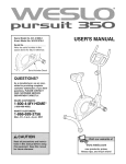
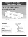
Before reading further, please familiarize yourself with
the parts that are labeled in the drawing below,
Handlebar
Left Handlebar
Handgrip Pulse Sensor
CD Holder
Fan
Console
CD Hayer
ight Handlebar
Water Bottle Holder*
FRONT
Flex Bar
Pedal
Wheel
BACK
Leveling Foot
Power Jack
RIGHT SiDE
*No bottle is included
4
AssemMy requires two persons. PHace aHH
parts of the eHHpticaH
crosstrainer in a cHeared area and remove the
packing materiaHs, Do not dispose of the packing materiaHs until assembHy is compHeted, In addition to the
included allen wrenches, assembly requires a phillips screwdriver
_
_,
an adjustable
f
,,
wrench _._
, and a rubber mattet ,_
............
)
m
• ........
]
j
Refer to the drawings bellow to identify the smaHHparts needed for assembHy, The number in parentheses bellow
each drawing is the key number of the part, from the PART LHST on page 22, The number foHHowingthe key
number is the quantity needed for assembHy, Note: Some small parts may have been pre-assembted.
If a
part is not found in the parts bag, check to see if it has been pre-assembled.
M8 NyHon
Locknut (46)-4
M4 x 16mm
Screw (66)-12
M6 x 16mm Tapered
Button Screw (107)-8
M8 SpHit
Washer (94)-10
M8,5 SmaHH
Washer (53)-2
M4 x 16mm Round
Head Screw (45)-1
M4 x 14mm Round
Head Screw (93)-2
M8 x 19mm Shoulder
Screw (22)-2
M8 x 45mm Button
Screw (102)-4
M8 x 38mm Button
Screw (70)-2
M8 x 54mm Button
Screw (33)-4
MIO Washer
(99)-2
M4x 12mm Round
Head Screw (18)-2
M8 x 43mm Button
Bolt (50)-4
M10 x 35mm Carriage
Bolt (20)-2
M4 x 52mm Screw (98)-2
While another person lifts the front of the Frame (1),
thread a Leveling Foot (72) fully into the underside of
the Frame, Next, attach the Front Stabilizer (3) to the
front of the Frame with two M8 x 54mm Button Screws
(33) and two M8 Split Washers (94),
33
72
2, SHdethe StabilizerCover(31)ontotheFrame(1),
Next,moveandHfteachFUex
Bar(14)outoftheway
andslidetheStabilizerCoverontotheFrontStabilizer
(3),WhileanotherpersonUiftsthefrontofthe Frame,
attachtheStabilizerCoverto theFrontStabilizerwith
twoM4x 52mmScrews(98),
2
31
14
WiththeheUp
of a secondperson,carefullytip the
eHipticaU
exerciserontooneside,
92
/
MakesurethattheLeftandRightStabilizerEndcaps
(35,92)areon theRearStabilizer(4),
94
1
Attachthe RearStabilizer(4)tothe Frame(1)with
fourM8x 45mmButtonScrews(102)andfourM8
SplitWashers(94),
94
WiththeheUp
of a secondperson,carefullytip the
eHipticaU
exerciserbacktotheverticalposition,
35
HaveanotherpersonhoUd
the Upright(2)inthe positionshown,ConnecttheUpperWireHarness(86)to
the LowerWireHarness(87),Next,inserttheUpright
intotheFrame(1),BecarefuJto avoid disconnecting or pinchingthe WireHarnesses.Attachthe
UprightwithtwoM8x 54mmButtonScrews(33),two
M8x 38mmButtonScrews(70),andfourM8Split
Washers(94),Becarefulto avoiddamagingthe
WireHarnesseswith the ButtonScrews.
AttachtheWaterBottleHolder(91)tothe Upright(2)
withtwoM4x 16mmScrews(66),
HoldtheLeftandRightHandlebar
Covers(26,29)
aroundthe Upright(2)andtheindicated
tube,Press
the Handlebar
Coverstogetherandconnectthemwith
an M4x 16mmRoundHeadScrew(45),
HoldtheLeftandRightUprightCovers(34,38)
aroundthe Upright(2),Attachthe UprightCoverswith
twoM4x 14mmRoundHeadScrews(93),
6
34
Make sure the
wire harnesses
do not get
pinched and
damaged
during this
step.
29
66
\
86.
94
87
94
/
identify the Left Handiebar (9), which is marked with a
sticker, insert the Left Handiebar into one of the
HandHebar Legs (79); make sure that the HandJebar
Leg is turned so the hexagonaJ hobs are on the
indicated side, Attach the Left Handiebar to the
Handiebar Leg with two M8 x 43mm Button Boits (50)
and two M8 Nyion Locknuts (46), Make sure that the
NyJon Locknuts are seated in the he×agonat holes.
Do not futty tighten the Sutton Bolts yet.
9
L
\
_
Tube
Attach the Right Handbbar (not shown} to the
other Handlebar Leg (not shown} in the same way.
gonal
Hobs
Appiy a generous amount of the inciuded grease to the
Pivot Axie (108) and to the two M8,5 Smali Washers
(53), insert the Pivot Axie into the Upright (2) and center
it, Reappiy grease to both sides of the Pivot Axie,
22
1
53
identify the Left and Right Handiebars (9, 10), which
are marked with stickers, Siide a Handiebar Spacer
(25) onto the short tube on each Handiebar, and siide
the Handiebars onto the Pivot Axie (108), Make sure
that the Handlebars are on the correct sides.
Orient the two Handlebar Caps (23) as shown, and
press the small tabs on the Handlebar Caps into the
two Handlebar Spacers (25), Tighten an M8 x 19mm
Shoulder Screw (22) with an M8.5 Small Washer (53)
into each end of the Pivot Axle (108),
53 23
Apply a thin film of grease to the shaft of a Union Bolt
Set (27) and to the two Bushings (28) in the left
Handlebar Leg (79),
Attach the left Handlebar Leg (79) to the left Flex Bar
(14) with the Union Bolt Set (27),
See assembly step 5 above, Tighten the two M8 x
43mm Button Bolts (50) in the left Handlebar Leg (79),
Make sure that the M8 Nyton Locknuts (46} are
seated in the hexagonal hotes.
Repeat this step to attach the right Handlebar Leg
(79) to the right Flex Bar (14),
7
27
27
\,
14
8, identify the Left PedaU(13), Attach the Left PedaU to
the bft Fbx Bar (14) with an MIO x 35mm Carriage
BoUt(20), an MIO Washer (99), and a PedaU Knob (15)
as shown, Note: The Left PedaUcan be attached in
8
J
J
I
any of five positions (see HOW TO ADJUST THE
PEDALS on page 10),
13
20
12
Attach the Right PedaU(12) in the same way, Make
sure that both PedaUs are in the same position,
15
Loosen the eight indicated screws (A) in the Center
Handlebar (63),
/
Attach the Center Handlebar (63) to the Upright (2)
with eight M6 x 16mm Tapered Button Screws (107),
Do not tighten the Tapered Sutton Screws yet.
Retighten the eight screws (A) in the Center
Handlebar (63),
107
//
107
10, Refer to step 11, Remove the six M4 x 16mm Screws
(66) and the Left and Right Handlebar Covers (109,
110) from the Console (5),
10
Attach the CD Holder (114) to the Console (5) with
two M4 x 12mm Round Head Screws (18) as shown,
While another person holds the Console (5) in the
position shown, connect the wire harness on the
Console to the Upper Wire Harness (86), insert the
excess wire harness down into the Upright (2),
, Wire
} Harness
Attach the Console (5) to the Upright (2) with four M4
x 16mm Screws (66), Be carefut to avoid pinching
the wire harnesses.
66
8
11. Attach the Left HandUebar Cover (109) to the ConsoUe
(5) with three M4 x 16mm Screws (66), Attach the
Right HandUebar Cover (110) in the same way.
11
See assemMy step 9. Tighten the eight M6 x 16mm
Tapered Button Screws (107).
110
109
66
66
12. Hug one end of the Power SuppUy (115) into the jack
at the rear of the eHipticaUcrosstrainer. Hug the other
end of the Power SuppUy into an appropriate outlet
that is propedy installed in accordance with aH UocaU
codes and ordinances,
\
12 :_,
\
\
Power
Jack
/
Note: The ConsoUe (5) can be operated with batteries
(not incUuded) instead of the Power SuppUy (96) if
desired, To install batteries, follow the instructions
beUow.
_
96
See the inset drawing, Press the indicated tab on the
battery drawer and pull the battery drawer down,
Press four "D" batteries into the battery dips; make
sure that the batteries are oriented as shown by
the markings inside of the battery clips. Then,
close the battery drawer, Note: Alkaline batteries are
recommended,
Batteries
Drawer
Tab
13. Make sure that aH parts of the elliptical crosstrainer
are properly tightened. Note: Some hardware may
be left over after assembly is completed, To protect the floor or carpet from damage, place a mat under the
elliptical crosstrainer.
9
HOW TO USE THE ELUPTICAL
HOW TO EXERCISE ON THE ELUPTICAL
CROSSTRAINER
CF{OSSTRAINER
To dismount the elliptical crosstrainer, wait until the
pedals come to a complete stop, Note: The eJliptioaJ
crosstrainer
does not have a free whee!; the pedals writ continue to move until the flywheel stops.
When the pedals are stationary, step off the highest
pedal first, Then, step off the lowest pedal,
To mount the eHiptbaUcrosstrainer, hoUdthe center ham
dbbar and step onto the pedaUthat is in the bwest
position, Then, step onto the other pedak Push the
pedaUs until they begin to move with a continuous
motion, Note: The crank arms (inside of the side
shields) can be turned in either direction. It is recommended that you turn the crank arms in the
same direction that you pedal a bicycle; however,
for variety, you can turn the crank arms in the
opposite direction.
HOW TO ADJUST THE PEDALS
The motion of
1
Side
10
the pedals is
Bolt
determined by
Flex
their positions on
Bar
the flex bars,
There are five
positions, To
adjust each
pedal, first
Pedal
loosen the knob
Knob
beneath the
pedal, Next,
push the bolt
upward, slide the pedal forward or backward to the
desired position, and then retighten the knob, Make
sure that both pedals are in the same position,
I
I
I
I
FEATURES OF THE CONSOLE
sonal trainer in your home, Using the built:in CD player,
you can play special iFIT,com CD programs, iFIT,eom
CD programs automatically control the resistance of
the pedals and prompt you to vary your pace while a
personal trainer coaches you through every step of
your workout, High:energy music provides added moti:
vation, Two iFIT.eom CDs are included; to purchase
additional CDs, call toll-free 1-800-735-0788.
The advanced console offers a selection of features
designed to make your workouts more enjoyable and
effective, When the manual mode of the console is
selected, the resistance of the pedals can be changed
with the touch of a button, As you work out, the con:
sob win provide continuous exercise feedback, You
can even measure your heart rate using the buNt:in
handgrip pulse sensor,
Using a stereo audio cable (available at electronics
stores), you can also connect the elliptical crosstrainer
to your VCR and TV and play iFIT, com video programs,
iFIT, eom video programs offer the same benefits as
iFIT, com CD programs, and allow you to enjoy breath:
taking scenery while you exercise, To purchase
iFIT, com videocassettes,
call toll-free 1-800-7350768.
The console also offers six Smart programs, Each pro:
gram automatically changes the resistance of the ped:
als and prompts you to increase or decrease your pace
as it guides you through an effective workout, in addi:
tion, the console features two Heart Rate programs
that change the resistance of the pedals and prompt
you to vary your pace to keep your heart rate near a
target heart rate as you exercise,
You can even connect the elliptical crosstrainer to your
home computer, go to our Web site at www, iFIT,com,
and access programs directly from our Web site,
Explore wwwJFIT.com for more information.
The console also features iFIT,oom interactive technol:
ogy, Having iFIT,eom technology is like having a per:
11
To use the manual mode of the consote, see the
instructions bellow, To use a Smart program, see
page 14. To use a Heart Rate program, see page 15.
To use an iFlT.eom CD program, see page 16. To
use an iFlT.eom video program, see page 19. To
use a program directly from our Web site, see
page 19.
every few seconds, if you use the handgrip pulse
sensor, the display will also show your heart rate
(see step 5 on page 13),
The center of
the targe disptay
wili show the
elapsed time and
your pedalling
pace (in minutes
per mile), The display wiii change from one number to the other every few seconds, Note: When a
program is selected (except for Heart Rate program 2), the display will show the time remaining
in the program instead of the elapsed time,
HOW TO USE THE MANUAL MODE
Turn on the console.
Make sure that the transformer is piugged in or
that batteries are installed in the console (see
assembHy step 12 on page 9).
The lower section of the targe
display wiii show
_PEE_
your pedaling
speed, your pedaling pace (in revolutions per minute), and the resistance level.
The display will change from one number to the
next every few seconds.
To turn on the console, press the On/Reset button
or begin pedaling. (The On/Reset button is the
button just above the iarge dispiay.)
Select the manuaJ mode.
Each time the console is
turned on, the manuai
mode wHi be selected, if a
Note: The consoJe can show
speed and dis_PEED
tance in either
miles or kilometers. The ietters
MPH or KM/H wili appear in the Hewersection of
the large display to show which unit of measurement is selected, To change the unit of measurement, first hold down the Program button for a few
seconds, An E (for English) or an M (for metric) will
appear in the lower section of the large display,
Press the Resistance + button to change the unit
of measurement, Then, press the On/Reset button,
Note: When the batteries are replaced, it may be
necessary to reselect the desired unit of measure°
merit,
program has been selected, reselect the manuai
mode by pressing the
Program button repeatedly until the letters RPM
appear in the smali dispiay.
Begin pedaJing and change the resistance
the pedals as desired.
of
As you pedal, change the resistance of the pedals by pressing the Resistance + and - buttons.
There are ten resistance levels; level 10 is the
most challenging. Note: After the buttons are
pressed, it will take a few seconds for the resistance to reach the selected level.
Follow your progress with the targe display and
the small display.
The small disptay will
show your pedaling pace
(in revolutions per minute),
The indicator bar in the
The upper section of the large
display wii[
show the dis-
7
RPM
small display will increase
or decrease in length as
indicator Bar
you increase or decrease
your pedaling pace, Note:
When you use a Heart Rate program, the small
display will show your heart rate instead of your
pedaling pace (see step 5 on page 13),
tance you have
pedalled and the
numbers of calories and fat calories you have
burned (see FAT BURNING on page 22). The dispiay will[ change from one number to the next
12
To reset the dispUays, press the On/Reset button,
Turn on the fan if desired.
Measure your heart rate if desired.
To turn on the
fan at low speed,
press the fan
button, To turn
on the fan at
If there are
thin sheets of
pJastic on the
metaJ contacts
on the hand-
high speed,
press the fan
button a second
time, To turn off
grips, peel off
the plastic. To
use the handgrip puUsesensot, hoUdthe
handgrips with
your paUms resting against the
metaUcontacts, Avoid moving your hands or
squeezing the handgdps too tightly; e×ces_
sive movement or pressure may interfere with
heart rate readings. When your puUse is detected, the heart-shaped indicator in the UargedispUay
wHUflash each time your heart beats, and your
heart rate wHUbe shown,
the fan, press the fan button a third time, Note: if
the fan is turned on but the pedals are not moved
for thirty seconds, the fan will automatically turn
off,
Rotate the thumb wheel on the right side of the
fan to pivot the fan to the desired angle,
When you are finished exercising,
wilt automatically
turn off.
the console
If the pedals are not moved for a few seconds,
the displays will pause and the time will flash in
the large display, If the pedals are not moved and
the console buttons are not pressed for a few
minutes, the console will turn off to conserve the
batteries,
For the most accurate heart rate reading, continue
to hold the handgrips for about 30 seconds, Note:
When you first hold the handgrips, the large display will show your heart rate continuously for 30
seconds, The display will then show your heart
rate along with other feedback modes,
13
HOWTO
appears at the tip
of each arrow
(see the drawing
at the right), Note:
When the word
TARGET does not
USE A SMART PROGRAM
Each Smart program wiii automatically change the
resistance of the pedals and prompt you to increase or
decrease your pace as it guides you through an effective workout, Programs 3 and 4 are weight loss programs, programs 5 and 6 are aerobic programs, and
programs 7 and 8 are high-performance programs,
appear in the
small display, your
actual pedaling pace wiii be shown, Important:
The target pace is intended only to provide a
goa!. Your actuaJ pace may be slower than the
target pace, especially dudng the first few
months of your exercise program. Make sure
to pedal at a pace that is comfortable for you.
Follow the steps below to use a Smart program,
Turn on the console.
See step 1 on page 12,
During the last three seconds of each period, a
series of tones will sound and the time will flash in
Select one of the Smart programs.
the large display, The resistance of the pedals will
then change if a different resistance level is programmed for the next period, in addition, the
number of arrows in the small display will change
if a different target pace is programmed for the
next period,
Each time the console is
turned on, the manual
mode wiii be selected, To
select a Smart program,
press the Program button
repeatedly until the number 3, 4, 5, 6, 7, or 8
appears in the small display,
Begin pedaling
_'/7
indicator
Bar
During the program, the center of the large display will show the time remaining in the program,
if you stop pedaling for a few seconds, the displays will pause and the time will flash, To restart
the program, resume pedaling,
to start the program.
Follow your progress
Each Smart program consists of either 20 or 30
one-minute periods, One resistance level and one
target pace are programmed for each period,
Note: The same resistance level and/or target
pace may be programmed for two or more consecutive periods,
with the large display.
See step 4 on page 12,
Measure your heart rate if desired.
See step 5 on page 13,
When you begin pedaling, the resistance of the
pedals will automatically change to the resistance
level programmed for the first period, Note: if the
resistance level is too high or too low, you can
change it by pressing the Resistance buttons,
Turn on the fan if desired.
See step 6 on page 13,
When you are finished exercising,
wilt automatically
turn off.
The target pace for the first period wiii appear in
the small display for a few seconds, and the
arrows in the small display will help you to pedal
at the target pace--simply increase or decrease
your pace until one segment of the indicator bar
See step 7 on page 13,
14
the console
to operate properly, Each time you hold the
handgrips, keep your hands on the metaJ contacts for at teast 30 seconds.
HOW TO USE A HEART RATE PROGRAM
Heart Rate program 1 is designed to keep your heart
rate between 65% and 85% of your maximum heart
rate during your workout, ('Your maximum heart rate is
estimated by subtracting your age from 220, For
exampb, if you are 25 years old, your maximum heart
rate is 195 beats per minute,) Heart Rate program 2 is
designed to keep your heart rate near a target heart
rate that you sebct,
Begin pedaling
Heart rate program 1 consists of 20 one-minute
periods, One resistance level and one target heart
rate are programmed for each period, (Note: The
same resistance level and/or target heart rate
may be programmed for two or more consecutive
periods,) Heart Rate program 2 is sixty minutes
long (you may choose to use only part of the program), The same resistance level and target heart
rate are programmed for the entire program,
Follow the steps below to use a Heart Rate program,
Turn on the consote.
When you begin pedaling, the resistance of the
pedals wiii automatically change to the resistance
level programmed for the first period,
See step 1 on page 12,
Select one of the Heart Rate programs.
Each time the consob is
turned on, the manual
mode will be sebcted. To
sebct a Heart Rate program, press the Program
button repeatedly until the
number 1 or 2 appears in
the small display,
As you pedal, the
arrows in the
small display will
=<
help you to keep
your heart rate
near the current
fj
indicator
Bar
Arrows-
target heart rate,
When you hold
the handgrip pulse sensor, the console will compare your heart rate to the current target heart
rate, if your heart rate is too far above or below
the target heart rate, the number of arrows in the
small display will change to prompt you to
increase or decrease your pace, When the number of arrows changes, change your pace until
one segment of the indicator bar appears at the
tip of each arrow, Important: The target pace is
intended only to provide a goal Your actuaJ
pace may be s!ower than the target pace,
especially during the first few months of your
exercise program. Make sure to pedal at a
pace that is comfortable
for you.
Enter your age or a target heart rate.
If program 1 is selected, the word AGE and the
current age setting will appear in the large display,
if you have already entered your age, press the
Enter button, if you have not entered your age,
press the small + and - buttons to enter your age,
and then press the Enter button, Once you have
entered your age, it will be saved in memory until
the batteries are replaced,
if program 2 is selected, the letters PLS and the
current target heart rate will appear in the large
display, If you do not wish to change the target
heart rate, press the Enter button, If you wish to
change the target heart rate, press the small +
and - buttons, and then press the Enter button,
The target heart rate can be from 70 to 170 beats
Hotd the handgrip
to start the program.
During the last three seconds of each period, a
series of tones wiii sound and the time wiii flash in
the large display, The resistance of the pedals will
then change if a different resistance level is programmed for the next period, Note: if the resistance level is too high or too low, you can adjust it
by pressing the Resistance buttons, However,
when the next period begins, the resistance will
automatically change if a different resistance level
is programmed for the next period,
pulse sensor.
It is not necessary to hold the handgrips continuously during a Heart Rate program; however, you
must hold the handgrips frequently for the program
15
The program wiii continue in this way until the
large display shows that no time remains in the
program, Note: if you stop pedaling for a few seconds, the program will end, To use the program
again, reselect it and start it at the beginning,
HOW TO USE IFmT.COMCD PROGRAMS
See step 4 on page 12,
When you use an iFiT,com CD program, a certified
personal trainer wiii guide you through your workout
while the program interactively controls the resistance
of the pedals and prompts you to increase or decrease
your pace, Note: To purchase iFIT.com CDs, call
toil-free 1-800-735-0788.
Turn on the fan if desired.
Follow the steps below to use an iFIT,com CD program,
Fottow your progress
with the targe display.
Turn on the consote.
See step 6 on page 13,
When you are finished exercising,
wilt automatically
turn off.
See step 1 on page 12,
the console
Select the iFIT.com mode.
See step 7 on page 13,
Each time the console is
turned on, the manual
mode wiii be selected, To
use an iFIT, com CD, press
the iFIT,com button, The
iFIT, com indicator will light
and the letters iF wiii
appear in the small display,
Insert an iFIT.com CD into the CD playen
To open the CD
player, slide the
center button on
the CD player
upward, Carefully
insert an iFIT, com
CD into the CD
player and then
close the lid,
Press the Play/Pause
program.
®®®®@@@
button to start the
To start the CD
program, press
the play/pause
button on the CD
player, A moment
after the button is
pressed, your personal trainer will begin guiding
you through your workout, Simply follow your personal trainer's instructions,
16
The CD program wH[ function in almost the same
way as a Smart program (see step 3 on page 14).
However, an electronic "chirping" sound wHUalert
you when the resistance UeveU
and/or the target
pace is about to change. Note: If the resistance
teveJ and/or the target pace does not change
when a "chirp" is heard, make sure that the
iFIT.com indicator is lit. In addition, adjust the
volume (see step 5 beJow}. If the volume is too
high or too Jow, the console may not detect the
program signaJs,
Follow your progress
To stop the program at any
time, press the
pUay/pause button and stop
pedaling. To
restart the program, press the pUay/pause button
and begin pedaling.
When you are finished exercising,
wilt automaticaJly turn off.
Note: To seUect a
different program on the CD,
press the
skip/search buttons on the CD
See step 4 on page 12.
Measure your heart rate if desired,
See step 5 on page 13.
Turn on the fan if desired,
See step 6 on page 13.
the consote
See step 7 on page 13.
Note: AJways remove iFIT.com CDs from the
CD player when you are finished using them,
NOW TO PLAY MUSIC CDS
®®®®@@
If desired, you can play your own music CDs in the CD
player. Before playing music CDs, select the manual
mode of the console (see HOW TO USE THE MANUAL
MODE on page 12).
pUayer.
Adjust the volume if desired.
To adjust the
voUume, press
the VoUume and + buttons on
with the Jarge display.
®®®®@®®
the CD player.
17
HOW TO CONNECT TO YOUR COMPUTER
CROSSTRAmNER TO YOUR VCR OR COMPUTER
Note: If your computer has a 1/8" LINE OUT jack,
see instruction A. If your computer has only a
PHONES jack, see instruction B.
HOW TO CONNECT TO YOUR VCR
A, Hug one end of a 1/8" to 1/8" stereo audio cable
(available at electronics stores) into the jack
beneath the console, Hug the other end of the
cable into the LiNE OUT jack on your computer,
Note: if your VCR has an unused AUDIO OUT jack,
see instruction A below, if the AUDIO OUT jack is
being used, see instruction
B. mfyou have a TV
with a buittqn VCR, see instruction
B.
A
A, Hug one end of a 1/8" to RCA stereo audio cable
(available at electronics stores) into the jack
beneath the console, Hug the other end of the
cable into the AUDIO OUT jack on your VCR,
[
,@I
:
[
A
'
"_
Audio
Cable
i
=1
=1
ooo
B, Hug one end of a 1/8" to 1/8" stereo audio cable
(avNlable at slectroNcs stores) into the jack
beneath the console, Hug the other end of the
cable into a 1/8" Y-adapter (avNlable at electronics
stores), Plug the Y-adapter into the PHONES jack
on your computer, Plug your headphones or speakers into the other side of the Y-adapter,
B, Hug one end of a 1/8" to RCA stereo audio cable
(available at electronics stores) into the jack
beneath the console, Hug the other end of the
cane into an RCA Y-adapter (available at electronics stores), Next, remove the wire that is currently
plugged into the AUDIO OUT jack on your VCR
and plug the wire into the unused side of the Yadapter, Hug the Y-adapter into the AUDIO OUT
jack on your VCR,
i pH°"Es
®i
u
Audio
Cable
Headphones/Speakers
Audio Cable
/
Wire removed from_
AUDIO OUT jack
18
1/8"
To stop the program at any time, stop pedaling
and press the pause button on your VCR, To
restart the program, press the play button on your
VCR and begin pedaling,
HOW TO USE mRT.COM VIDEO PROGRAMS
To use iFUT,com videocassettes, the eHiptbaU
crosstrainer must be connected to your VCR, See
HOW TO CONNECT TO YOUR VCR on page 18, To
purchase iFIT.com videocassettes,
call toll-free 1800-735-0788.
Fottow your progress
with the targe display.
See step 4 on page 12,
Follow the steps bebw to use an iFF, com video pro=
gram,
Measure your heart rate if desired.
See step 5 on page 13,
Turn on the console.
Turn on the fan if desired.
See step 1 on page 12,
See step 6 on page 13,
Select the iFIT.com mode.
When you are finished exercising,
wilt automatically
turn off.
Each time the consob is
turned on, the manuaU
mode wHUbe sebcted, To
use an iFUT,com videocas=
sette, press the iFUT,com
button, The iFF, com indicator wHUHght and the btters iF wHUappear in the
small dispUay,
the consoJe
See step 7 on page 13,
HOW TO USE PROGRAMS DIRECTLY FROM
OUR WEB SITE
Insert the iFIT.com videocassette.
Insert the videocassette into your VCR,
Press the play button on your VCR.
A moment after the play button is pressed, your
personal trainer wiii begin guiding you through
your workout, Simply follow your personal trainer's
instructions,
The video program wiii function in almost the
same way as a Smart program (see step 3 on
page 14), However, an electronic "chirping" sound
will alert you when the resistance level and/or the
target pace is about to change,
Our Web site at www, iFIT, com allows you to play
iFIT, com programs directly from the internet, To use
programs from our Web site, the elliptical crosstrainer
must be connected to your computer, See HOW TO
CONNECT TO YOUR COMPUTER on page 18, in
addition, you must have an intemet connection and an
internet sewice provider, A list of specific system
requirements is found on our Web site,
Follow the steps below to use a program from our
Web site,
Turn on the consote.
See step 1 on page 12,
Note: if the resistance JeveJ and/or the target
pace does not change when a "chirp" is heard:
Make sure that the iFIT.com indicator
Select the iFIT.com mode.
Each time the console is
turned on, the manual
mode wiii be selected, To
use a program from our
Web site, press the
iFIT, com button, The
is tit.
• Adjust the voJume of your VCR. if the volume
is too high or too low, the consote may not
detect the program signaJs.
iFIT, com indicator will light
and the letters iF wiii
appear in the small display,
Make sure that the audio came is properly
connected and that it is fully plugged in.
19
Go to your computer
connection.
and start an intemet
Start your Web browser, if necessary,
to our Web site at wwwJRT.com.
Follow the desired
step 3 on page 14), However, an electronic "chirping" sound will alert you when the resistance level
and/or the target pace is about to change,
and go
Follow your progress with the targe display.
See step 4 on page 12,
tinks on our Web site to
select a program.
Measure your heart rate if desired.
Foltow the onqine instructions
to start the
See step 5 on page 13,
program.
Turn on the fan if desired.
When you start the program, an on-screen countdown will begin,
See step 6 on page 13,
Return to the elliptical
pedaling.
crosstrainer
and begin
I When you are finished exercising,
wilt automatically
turn off.
When the on-screen countdown ends, the program wiii begin, The program wiii function in
almost the same way as a Smart program (see
MAINTENANCE
the console
See step 7 on page 13,
AND TROUBLESHOOTING
inspect and tighten all parts of the elliptical crosstrainer
regularly, Replace any worn parts immediately, The
elliptical crosstrainer can be cleaned with a soft cloth
and a small amount of mild detergent, Keep Hquids
away from the consote. Never use abrasives or
solvents.
cal crosstrainer to the desired location, Then,
one foot against one of the wheels and lower
tical crosstrainer, Due to the size and weight
elliptical crosstrainer, use extreme caution
moving and towering it.
place
the ellipof the
while
HOW TO LEVEL THE ELLIPTICAL CROSSTRAINER
CD PLAYER TROUBLESHOOTING
After the elliptical
crosstrainer has
been moved, make
sure that the ends
of both stabilizers
are touching the
floor, if the elliptical
crosstrainer rocks
if the CD player stops working or fails to respond,
remove the batteries and then reinstall them or unplug
the power supply and then plug it back in,
HOW TO MOVE THE ELLIPTICAL
CROSSTRAINER
Stand in front of
the elliptical
crosstrainer,
hold the center
and place one
foot against one
of the wheels,
Pull the handlebar until the
elliptical
crosstrainer can
be moved on the
front wheels,
and carefully
move the ellipti-
slightly during use,
turn one or both of
Leveling Foot
the leveling feet
under the front stabilizer until the rocking motion is
eliminated,
"
Handlebar
HANDGRIP PULSE SENSOR TROUBLESHOOTING
if the handgrip pulse sensor does not function properly,
see step 5 on page 13, Note: For optimal performance of the handgrip pulse sensor, keep the metal
contacts clean using a soft cloth and a small amount
of mild detergent, Never use alcohol, abrasives, or
chemicals.
20
CONDmTmONmNGGUmDEUNES
During the first few minutes of exercise, your body
uses easily accessible ca@ohydt:ate calories for energy. Only after the first few minutes of exercise does
your body begin to use stored fat calories for energy.
if your goal is to burn fat, adjust the intensity of your
exercise until your heart rate is near the lowest number in your training zone as you exercise.
- Before beginning this or any exercise program, consult your physician. This is especially important for persons over the age of
35 or persons with pre-e×isting health problems.
For maximum fat burning, adjust the intensity of your
exercise until your heart rate is near the middle number in your training zone as you exercise.
. The puJse sensor is not a medicaJ device.
Various factors may affect the accuracy of
heart rate readings. The pulse sensor is
intended only as an exercise aid in determining heart rate trends in general.
Aerobic
if your goal is to strengthen your cardiovascular sys=
tem, your exercise must be "aerobic." Aerobic exercise is activity that requires large amounts of oxygen
for prolonged periods of time. This increases the
demand on the heart to pump blood to the muscles,
and on the lungs to oxygenate the blood. For aerobic
exercise, adjust the intensity of your exercise until
your heart rate is near the highest number in your
training zone as you exercise.
The following guidelines wiii help you to plan your
exercise program. Remember that proper nutrition
and adequate rest are essential for successful results.
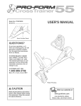
EXERCISE iNTENSiTY
Whether your goal is to burn fat or to strengthen your
cardiovascular system, the key to achieving the
desired results is to exercise with the proper
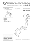
The proper intensity level can be found by using your
heart rate as a guide. The chart below shows recommended heart rates for fat burning, maximum fat
burning, and cardiovascular (aerobic) exercise.
165
155 145
140
I30
125
I15
_
103
C_
145 138
130
125
118 110
125
120
115
110
105
95
90
20
30
40
50
60
70
80
Exercise
WORKOUT
GUiDELiNES
Each workout should include the following three parts:
A warm-up, consisting of 5 to 10 minutes of stretching
and light exercise. A proper warm-up increases your
body temperature, heart rate, and circulation in preparation for exercise.
Training zone exercise, consisting of 20 to 30 minutes of exercising with your heart rate in your training
zone, Note: During the first few weeks of your exercise program, do not keep your heart rate in your
training zone for longer than 20 minutes.
A cooFdown, with 5 to 10 minutes of stretching. This
wili increase the flexibility of your muscles and wili
help to prevent post-exercise problems.
To find the proper heart rate for you, first find your age
at the bottom of the chart (ages are rounded off to the
nearest ten years). Next, find the three numbers above
your age. The three numbers are your "training zone."
The lower two numbers are recommended heart rates
for fat burning; the highest number is the recommended heart rate for aerobic exercise.
EXERCmSEFREQUENCY
To maintain or improve your condition, complete three
workouts each week, with at bast one day of rest
between workouts. After a few months of regular exercise, you may complete up to five workouts each week
if desired. The key to success is to make exercise a
regular and enjoyable part of your everyday life.
Fat Burning
To burn fat effectively, you must exercise at a relative=
ly low intensity level for a sustained period of time.
21
PART LiST--Model
Key
No. Qty.
1
2
3
4
5
6
7
8
9
10
11
12
13
14
15
16
17
18
1
1
1
1
1
1
1
1
1
1
2
1
1
2
2
1
2
2
19
20
6
2
21
22
2
2
23
24
25
26
27
28
29
30
31
32
33
34
35
36
37
38
39
4O
41
Description
No. PFEL91031
Key
No. Qty.
Rt203A
Key
No. Qty.
Description
Description
Frame
Upright
Front Stabilizer
Rear Stabilizer
42
43
44
45
2
1
1
1
FUywheeUBearing
Magnet
FUywheeUAxUe
M4 x 16mm Round
82
83
84
85
1
1
6
1
ConsoUe
Left Side ShieUd
Right Side SMeUd
Left Rear Side ShieUd
Left HandUebar
46
47
48
49
6
2
1
1
Head Screw
M8 NyUon Locknut
Crank Screw
Right Crank Arm
M6 x 38mm BoUt
86
87
88
89
1
1
2
2
Right HandUebar
Foam Grip
Right PedaU
Left PedaU
Flex Bar
Pedal Knob
50
51
52
53
54
55
4
1
1
2
1
1
M8 x 43mm
M6 x 18mm
"C" Magnet
M8,5 Small
"C" Magnet
Motor
90
91
92
93
4
1
1
2
Screw
Motor Washer
Water Bottle HoUder
Right Stabilizer Endcap
M4 x 14mm Round
Head Screw
Left Flex Bracket
Front Flex Bracket
56
57
1
2
Belt
M8 x 33mm Button Bolt
94
95
10
1
M8 Split Washer
Front Plate
M4 x 12mm Round
Head Screw
M6 x 26mm Flat Screw
58
59
60
12
15
2
M6 Washer
M6 Nylon Locknut
M6 Nut
96
97
98
1
1
3
Power Supply
Idler Assembly
M4 x 52mm Screw
MIO x 35mm Carriage
Bolt
Snap Ring
M8 x 19mm Shoulder
Screw
61
62
63
64
4
4
1
4
M5 Nylon Locknut
M5 x 14mm Bolt
Center Handlebar
M6 x 32mm Button
Screw
99
100
101
102
2
2
2
4
MIO Washer
Small Spacer
Large Spacer
M8 x 45mm Button
Screw
2
6
2
1
2
4
1
1
1
2
6
Handlebar Cap
Handlebar Bushing
65
66
67
2
22
2
Left Handlebar Cover
Union Bolt Set
Front Flex Bushing
Right Handlebar Cover
Center Cover
68
69
70
1
1
2
M8,5 Large Washer
M4 x 16mm Screw
M8 x 25mm Patch
Screw
Right Rear Side Shield
Reed Switch Clamp
M8 x 38mm Button
Screw
103
104
105
106
107
1
2
1
1
8
108
109
1
1
Alignment Rod
M6 Nut
Idler Bolt
Idler Adjustment Screw
M6 x 16mm Tapered
Button Screw
Pivot Axle
Left Handlebar Cover
Stabilizer Cover
Wheel
M8 x 54mm Button
Screw
71
72
73
74
2
3
2
2
Handlebar Grip
Leveling Foot
M5 x 16mm Screw
M4 x 25mm Round
110
111
112
113
1
10
2
1
Right
M4 x
M6 x
Rear
1
1
1
1
1
1
2
1
Left Upright Cover
Left Stabilizer Endcap
Left Crank Arm
Pulley
Right Upright Cover
Crank
Crank Bearing
Flywheel
75
76
77
78
79
80
81
1
1
1
1
2
1
1
Head Screw
Left Inner Shield
Spring
Reed Switch
Reed Switch Bracket
Handlebar Leg
Side Shield Cover
Right Inner Shield
114
115
1
2
#
#
#
2
1
1
CD Holder
M8 x 43mm Button
Screw
Allen Wrench
Grease
User's Manual
Button BoUt
BoUt
Bracket
Washer
Right FUexBracket
Large Frame Spacer
M4 x 12mm Tap Screw
AssemMy
Upper Wire Harness
Lower Wire Harness
FUexBracket Spacer
M8 x 25mm Button
Handlebar Cover
14mm Screw
30mm Flat Bolt
Plate
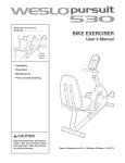
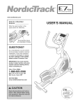
Note: "#" indicates a non-illustrated part, Specifications are subject to change without notice, See the back cover
of this manual for information about ordering replacement parts,
22
m
x
\
\
0
\
\
23
107
24
31
108
29 2-_
24
l
Z
_94_- .... 94
66
24
46
25
79
86
24
O_
0
t#
87
!
,46
Z
/ 47
64
53
0
m
5O
//
83
281
39
32
21
m
56
¢0
O
00
111
28
19
14
111
37
94
100
"36
92
102
J
111
100
59
::D
PO
o
o3
HOW TO ORDER REPLACEMENT
PARTS
To order repUacement parts, simpUy call our Customer Service Department toll=free at 1-800-999-3756, Monday
through Friday, 6 a,m, until 6 p,m, Mountain Time (excluding holidays), To heUpus assist you, phase be
prepared to give the following information when calling:
The MODEL NUMBER of the product (PFEL91031)
The NAME of the product (PROFORM _ 1080 S eHiptbaUcrosstrainer)
The SERIAL NUMBER of the product (see the front cover of this manuaU)
The KEY NUMBER and DESCRPTUON of the part(s) (see page 22)
LIMITED WARRANTY
iCON HeaUth & Fitness, Unc,(iCON), warrants this product to be free from defects in workmanship and
materiaU, under normaU use and service conditions, for a period of ninety (90) days from the date of purchase, This warranty extends only to the original purchaser, ICON's obligation under this warranty is limited to replacing or repairing, at ICON's option, the product through one of its authorized service centers,
All repairs for which warranty claims are made must be pre-authorized by ICON, This warranty does not
extend to any product or damage to a product caused by or attributable to freight damage, abuse, misuse, improper or abnormal usage or repairs not provided by an ICON authorized service center; products
used for commercial or rental purposes; or products used as store display models, No other warranty
beyond that specifically set forth above is authorized by ICON,
ICON is not responsible or liable for indirect, special or consequential damages arising out of or in connection with the use or performance of the product or damages with respect to any economic loss, loss
of property, loss of revenues or profits, loss of enjoyment or use, costs of removal or installation or other
consequential damages of whatsoever nature, Some states do not allow the exclusion or limitation of incidental or consequential damages, Accordingly, the above limitation may not apply to you,
The warranty extended hereunder is in lieu of any and all other warranties and any implied warranties of
merchantability or fitness for a particular purpose is limited in its scope and duration to the terms set forth
herein, Some states do not allow limitations on how long an implied warranty lasts, Accordingly, the above
limitation may not apply to you,
This warranty gives you specific legal rights, You may also have other rights which va n, from state to state,
ICON HEALTH & FITNESS, INC., 1500 S. 1000 W., LOGAN, UT 84321-9813
Part No, 208502 R1203A
Printed in China © 2003 iCON Health & Fitness, Inc,


![PLAS A O ]-OR](http://vs1.manualzilla.com/store/data/005852706_1-5db0b7ed584537f0e62af161fb124638-150x150.png)