1
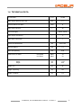
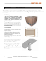
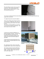
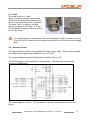
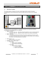
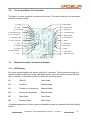
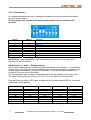
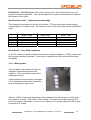
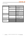
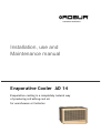
Installation, use and Maintenance manual Evaporative Cooler AD 14 Evaporative cooling is a completely natural way of producing refreshing cool air for warehouses or factories EDITION: 04/2014 Code: D-LBR483 This manual has been drawn up and printed by Robur S.p.A.; whole or partial reproduction of this manual is prohibited. The original is filed at Robur S.p.A. Any use of this manual other than for personal consultation must be previously authorised by Robur S.p.A. The rights of those who have legitimately filed the registered trademarks contained within this publication are not affected With the aim of continuously improving the quality of our products, Robur S.p.A. reserves the right to vary the data and contents of this manual without prior notice. Installation, use and Maintenance manual - ed. 04/14 2 FOREWORD This manual is for anyone who must install or use the Robur AD 14 evaporative cooler. This manual especially applies to the plumbers who must install the evaporative cooler, to the electrician who must connect the heating unit to the electrical system and to the end user who must check that it functions properly. This manual is also for the technicians regarding the principle maintenance operations. CONTENTS 1 – General Information ………………………………………………………….. 4 2 – Installation …………………………………………………………. 7 3– Control system …………………………………………………………. 14 4 – Commissioning ……………………………………………………….... 20 5 – Operating of the unit and Settings ………………………………… 23 …………………………………………………. 28 Evaporative Cooling Operating Instruction …………………………………. 34 6 – Maintenance and Service 3 Installation, use and Maintenance manual - ed. 04/14 SECTION 1 GENERAL INFORMATION In this section you will find the general instructions to follow for the installation and use of the AD 14 evaporative cooler, a brief mention of the operation of the unit, the constructive characteristics and the technical data. 1.1 GENERAL WARNING This manual is an integral and essential part of the product and must be given to the user. This unit must be exclusively used for the purpose it was intended. Any other use is to be considered improper and therefore dangerous. This unit must be exclusively used for the purpose it was intended. Any other use is to be considered improper and therefore dangerous. The manufacturer will not be held responsible for damages resulting from installation errors or failure to comply with the manufacturer’s instructions. The unit must be installed in accordance with local regulations. ) In case of failure and/or poor operation, isolate the unit (disconnect it from the power supply and close water supply valve), do not attempt any repair or direct servicing. Call qualified service engineers only. The manufacturer’s authorised service centres using only original spare parts must only carry out any repair to the products. Misapplication of the above might compromise the safety of the unit. To ensure unit efficiency and correct operation, it is essential that qualified service engineers carry out annual maintenance following the manufacturer’s instructions. Should the unit be sold or transferred to another owner, please ensure that the manual remains with the unit for use by the new owner and/or installer. Before turning the heater on, a qualified service engineer must check: - that the electric ratings are the same as those on the data plate. - that water supply pressure are the same as those on the data plate.. If the cooler is turned off for prolonged periods of time, close the water supply valve and cut off the electrical supply. Installation, use and Maintenance manual - ed. 04/14 4 1.2 OPERATION OF THE UNIT Evaporative cooling is a completely natural way of producing refreshing cool air that have been specifically designed for the cooling of industrial and commercial building. It is designed for outdoor installation with down, top and side discharge and also as internal suspended cooler. Cooling is provide by Evaporative heat exchange which take advantage of the principles of the latent heat of evaporation where tremendous heat is exchanged when water evaporates. It makes use of the free latent energy in the atmosphere. Water is brought into the cooler from the mains water supplì and is pumped up to the top of the unit using circulation pump. The water is then dispersed over the Celdek pads using a water distribution system which allows the water to flow continually over the pad. The pads become satured, air is drawn through the pads and the water evaporate causing the air to cool. The cool air is then ducted round the building to provide cooling by means of an axial fan. The control system comprises of a main control panel which controls all components by communicating with a wall mounted control box and a set of external inputs (like thermostat, humidistat, timer, alarm, etc) 1.3 CONSTRUCTIVE CHARACTERISTICS Evaporative Cooler AD 14 is supplied with: 5 - The cooling pads are cellulosa based 680x850x100 mm thickness - Axial fan 1 to 5 speeds and high static pressure - Control board with microprocessor is the heart of control system and connected to a unique level probe system empties completely the sump whenever the system goes out of cooling mode, so that no stagnant water remains in the system and when the water approaches the scale index. It is supplied with 30m cable - Circulation pump is pumping the water from the sump over the pads via a water distribution system. 50W, 30 l/min - 4 water level probes to check water level into the sump. They also check through electronic board the quantity and quality of the water. - Water supply valve and drain valve controlled by electronic board - Wall mounted control box could be connected to thermostat to give automatic control. Facility to connect to timer, humidistat and fire alarm contact. - Water sump and side panels are injection moulded structural from polypropylene. The cabinet is UV stabilized and corrosion free. Installation, use and Maintenance manual - ed. 04/14 1.4 TECHNICAL DATA Air Flow Rate Water Supply Pressure min/max Minimum Water Flow Rate Water Sump Capacity m3/h 14.000 bar 1/7 l/min 8 l 23 Electrical Supply 230 V – 50 Hz Water Supply Connection “ ½ Water Drain Connection “ 1 Square Duct Dimensions mm 645 x 645 Axial Fan Rating kW 1,5 Water Pump Rating kW 0,05 dB(A) dB(A) 74 64 mm mm mm 1.170 1.170 950 Weight: dry kg 92 Weight: operating kg 127 Weight: transport kg 117 Noise Level @ 3 meter Dimensions : Width Depth Height max speed min speed Installation, use and Maintenance manual - ed. 04/14 6 SECTION 2 INSTALLATION This installation section describes the installation of the cooler with standard controls. If other control such as a thermostat or humidistat is to be used the 5 speed control panel instructions must be consulted 2.1 - Delivery The unit is delivered mounted on a pallet which is used to support the unit during installation. A protective cardboard cover is, together with internal polystyrene pads, banded to the pallet. This is a fragile item and must be handled carefully. The maximum stacking height is 2. Once removed from the pallet take great care not to damage the drain which protruded from the bottom of the unit. 2.2 - Installation The dimensions of the unit are shown in the diagram opposite. A minimum of 300mm clearance must be provided around the unit to enable the side panels to be removed. The operating weight of the unit, when full of water is 92Kg AD 14 is designed to be supported from a plain square duct with nominal external dimensions 645mm x 645mm. Note that due to the variation in the moulding of plastics there may be some variation in these dimensions – the final duct must be manufactured to fit the cooler. 7 Installation, use and Maintenance manual - ed. 04/14 The side frames are also act as a guard for the fan. Set screws prevent their removal unless a tool is used to comply with guarding regulations. To remove the side panel first remove the security screws. Then lift the panel and the top edge can be removed. To replace the panel reverse the above. There are location points for the cooler to sit on the duct. When the cooler sits on a level duct these points ensure the cooler is level. The cooler must be installed on a level to ensure safe and efficient operations. The duct enters the cooler 30mm. A typical roof mounted installation to a plenum chamber is shown. Checks must be made that the roof structure can support the full operating weight of the system plus the ductwork and plenum chamber. Coolers should not be placed where the intake could be contaminated with fumes, heavy dust etc. On a sloping roof the cooler is normally installed with the drain at the lowest point. The cooler must be mounted sufficiently high so that the drain connection can be made – typically 150mm clear from the roof on the upper side Drain Water Installation, use and Maintenance manual - ed. 04/14 8 The cooler is then fixed to the ductwork using fixings appropriate for the duct material. It is recommended than a minimum of 3 fixings are made on each side. Appropriate weather proofing should be made according to the roof structure and local weather conditions. It is normal to support the weight of the cooler on supports on the underside of the roof. 2.3 - Support brackets installation Every Evaporative Cooler AD 14 is standard delivered with no. 2 adjustable support brackets. The purpose of the brackets is to support the heaviest side of the cooler, where the internal water tank is positioned, in case the AD14 Cooler is installed directly on the air duct system (standard down discharge) – see picture below. With this kind of installation, and in particularly hot climate conditions (if the cooler is exposed directly to the sun for many hours), it is better that the heaviest side of the tank (where the water is deepest), is fixed with these brackets, so that the plastic part of the water tank get more stability. NOTE These support brackets must be used only if the cooler is NOT standing on the 4 points of support. 9 Installation, use and Maintenance manual - ed. 04/14 To install the brackets, please proceed like follows: - install the cooler, connecting the cool air down discharge to the duct system below - fix the brackets to the duct as shown in the diagram below - adjust the brackets so that the water tank is levelled and well-supported by the brackets 2.4 – Services connections The services are all fed from the bottom at the points shown Installation, use and Maintenance manual - ed. 04/14 10 2.5 – Electrical supply The electrical connections must be done by Qualified service engineering. Before beginning this operation, cut off the electrical supply. 1. Check that the voltage supply is 240/50Hz single-phase 2. Carry out the electrical connections accordino to the installation wiring diagram 3. When connecting, censure that the earth wire is longer than the live wires, so that i twill be the last wire to break if the supply cable is stretched, thus ensuring a good earth continuità. electrical safety of the unit attained only when the unit itself is correctly ) The connected and efficiently grounded according to the exhisting safety standards. 4. The unit should be connected to the electric supply line by means of an omnipolar switch with a minimum contact opening of 3 mm. An omnipolar switch ia a “Double pole isolating switch”, i.e. a switch capable of disconnecting both on phase and neutral. This means that when the switch is opened, both contacts are disconnected. 2.6 - Water The cooler must be supplied with fresh, mains water to maintain hygienic and efficient operation. It is connected to the underside of the cooler using a 1/2” bsp connection. The water pressure must a minimum of 1 bar and a maximum of 7 bar with a total flow rate of 500l/hr. It is recommended that a ‘double check’ valve is fitted. All water installations should conform to local regulations. A flexible connection pipe is provided. It is recommended that this used to prevent stress on the water solenoid valve fitting 11 Installation, use and Maintenance manual - ed. 04/14 2.7 - Drain The drain outlet is a 1”bsp fitting. The drain capacity must exceed 2000 l/hr to an appropriate disposal point which conforms to local water regulations. The drain valve, on delivery, requires fitting to the base of the sump. A 1” bsp nut and gasket is supplied which are used to fix to the sump. To avoid damage to the water and drain valves during the winter months of non-use of the AD 14 it is necessary to discharge the hydraulic circuit (including water supply pipe). 2.8 – Remote Control The wall mounted controller comes fitted with a 30m control cable. This can be extended up to 200m using appropriate standard 16 core 0.75mm2. The control voltages contained within these controllers are +/-12V. The wiring diagram for the controller is shown below. The Automatic mode will be discussed in detail later. The control cable is 16 cores. It is connected to the wall control box by two terminal blocks. Installation, use and Maintenance manual - ed. 04/14 12 The first terminal block is used for all of the manual controls (plus the purple automatic cable). The second terminal block is for the Alarm, Timer, Humidistat and Thermostat. Note that the Alarm and Timer contacts must be made for the cooler to operate. 13 Installation, use and Maintenance manual - ed. 04/14 SECTION 3 3.1 CONTROL SYSTEM Overview of system The control system comprises of a main control panel which controls the above components by communicating with a wall mounted control box and a set of external inputs. On/Off Man/Auto Velocità 1 Termostato On/Off Velocità 2 Timer On/Off Velocità 3 Velocità 4 Igrostato esterno On/Off Velocità 5 Cool/Vent Remote control Igrostato interno On/Off Allarme antincendio On/Off Allarme The purpose of the control system in evaporative coolers is to control the following functions which are accessible by the operator • Power - ON/OFF o Turns the cooler on - starts the fan and operates in cool or vent as selected o Turns the cooler off – stops all functions and cooler drains automatically • Auto - Man/Auto o In manual mode the cooler follows the set fan speed and cool/vent mode o In Auto the fan speed and cool/vent mode are automatically set according to the status of the thermostat and humidistat. • • Fan Speeds 1 to 5 o Manual setting of fan speed Cooling - Cool or Vent mode o Vent mode Water circuit is disabled Sump drains automatically o Cool mode Water circuit is enabled • Fill cycle enabled • Bleed control enabled Installation, use and Maintenance manual - ed. 04/14 14 o Alarm Highlights the system has an error The number of pulses indicates the fault present. The purpose of the system is to control the following components L1 L2 L3 L4 F1 V1 P1 V2 Water in Water out V1 V2 L1 L2 L3 L4 P1 F1 Water inlet valve – controls the water into the cooler Drain valve – controls the drain from the cooler Level Probe – controls the water levels in the cooler Level Probe – controls the water levels in the cooler Level Probe – controls the water levels in the cooler Level Probe – controls the water levels in the cooler Circulation Pump – circulates the water onto the cooling media Fan – double wound single phase fan motor 15 Installation, use and Maintenance manual - ed. 04/14 3.2 - The Control Board- The Controller The heart of control system is a printed circuit board. The layout with the key input/output locations is shown below N - Spare A -LED Display O Drain - B - Dip switches P – Drain fuse C - RS232 Port Q -Circulation pump D - ISP System Port R -Circ. Pump fuse E - Water probes S - Scavenge pump F - External alarm T - Scav. Pump fuse. G - Timer U - Live In H - Humidistat V- Neutral In I -Thermostat W - Earth In J - Spare Capacitor X Motor - K - Wall control Y - Fan L - Water Inlet Valve - 3.3 Detailed Description of Input and Outputs 3.3.1 - LED Display On power-up this displays the salinity setting for 3 seconds. During normal running this shows a single red dot at the lower right hand corner unless an alarm has occurred and this is retained. In an alarm condition it shows the following codes 01 – Slow fill Auto Reset 02 – Overflow Manual Reset 03 – Probes out of sequence Manual Reset 04 – Abnormal evaporation Manual Reset 05 – Slow Drain Auto Reset 06 – External Alarm Auto Reset A detailed explanation of these faults and possible causes are detailed in the fault finding section. Installation, use and Maintenance manual - ed. 04/14 16 3.3.2 - Dip Switches All variable parameters are set by changing the positions of the dip-switches located on the main control board. These changes can only be made during mains power off for a minimum of 5 seconds. Switch Default 1 2 3 4 5 6 7 8 Off Off On On Off Off Off Off Function Pre Cool Cycle Salinity 1 Salinity 2 Salinity 3 24 hr dry cicle Off speed 1.390 on max speed 1.200 Off speed1.390 On max speed 1.000 Enables complete stop in Auto Dip-Switch 1 – Pre cool cycle: If this is enabled the fan does not start until after 5 minutes of water circulation. Dip-Switches 2, 3 and 4 – Salinity settings As the water evaporates the scale forming salts increase in concentration. To control this function the cooler drains the sump completely when a set concentration is reached. This is determined volumetrically using the level probes. These dip switches determine the number of fill cycles prior to this drain. The concentration factor should be calculated based on the analysis of the water used. The default setting from the factory is: 2 Off, 3 On, 4 On which is 30% bleed rate Note that the set number of fill cycles is displayed by the control board LED for 3 seconds when power is first applied. 17 2 3 4 Concentration Bleed OFF OFF OFF OFF ON ON ON ON OFF OFF ON ON OFF OFF ON ON OFF ON OFF ON OFF ON OFF ON No drain 2,2 2,8 3,4 3,9 4,5 5,1 5,7 0% 46 % 36 % 30 % 25 % 22 % 20 % 18 % Installation, use and Maintenance manual - ed. 04/14 Dip-Switch 5 – 24hr Dry Cycle: The cooler will dry out for 30 minutes during every 24 hours of continuous operation. This can be applied to in certain circumstances to improve the hygiene of the cooler Dip-Switches 6 and 7 – Maximum speed settings This enables the top speed of the fan to be limited. This may be used to either reduce overall capacity or reduce noise. The standard motor used is a double wound 4 pole/6pole motor. Speed 5 4 3 2 1 Dip –switch default 6 OFF - 7 OFF 1390 1220 1050 870 600 6 ON - 7 OFF 1200 1090 980 870 600 6 OFF - 7 ON 1000 960 910 870 600 Dip-Switch 8 – Auto Stop Conditions In ‘AUTO’ mode the default condition is the cooler remains at Speed 1, ‘VENT’ mode when the set point has been achieved. If this switch is enabled then the cooler will shut down completely. 3.3.3 – Water probes The four water level probes are base on magnetic floats which operate reed switches. They provide the input for the following functions. At start-up the low level probe is checked – if it is covered then the cooler drains fully prior to starting the water cycle. When in ‘COOL’ mode water enters the sump, with both inlet valves open, until the high level probe is covered. Inlet valve V1 then closes. The water then evaporates until the Low Level probe is uncovered. Valve V1 then opens (V2 is already open) and fills to High Level when V2 closes. Installation, use and Maintenance manual - ed. 04/14 18 Inlet valves V1 and V2 are alternated in this way to validate their operation. If either one fails then the water will rise to the Very High Level which will result in an alarm condition and the other valve will close. This gives a high degree of protection from over-flow. This cycle continues according to the dip switch 2, 3&4 settings. When the set point is reached the water is then drained until Low Level probe is uncovered. When the low level probe is uncovered the system then waits for 2 minutes and then runs the water for 6 seconds to drain to clean the sump... The drain then stays open for a further 20 seconds and the recommence the fill cycle. During drainage the scavenge pump is enabled. This scavenge pump is typically used in the SDU internal cooler to pump away drain water where it impossible to use a gravity fed drain. The cooler drains down completely when stop or vent is selected. If low level probe is covered during this then the drain valve opens and scavenge pump runs as described above. 3.3.4 – External alarm This contact must be made at all times. This can be used to stop the machine when linked to: Fire alarm system Smoke detectors 3.3.5 – Timer This switches the cooler on and off. This contact must be made at all times for the cooler to run. The cooler will re-start at the previous settings. 3.3.6 – Humidistat In automatic mode this disables the cool function and water circulation in Automatic mode. This is typically used to limit the relative humidity in a building or to disable the cooling when the external humidity exceeds a specified value 3.3.7 – Thermostat In automatic mode the control system monitors the thermostat every 10 minutes. When ‘AUTO’ mode is selected, the cooler starts at speed 3 in cool mode. The thermostat contact is the monitored. If the thermostat shows a closed contact then the cooler will increase the speed of the fan by one increment up to the maximum speed 5 with cool. If the thermostat shows an open contact, then the cooler will decrease the speed of the fan by one increment until it either stays at VENT/Speed 1 or shuts down completely. Note the OFF/OFF status is only enabled by using dip switch 8. Default is the cooler will slow down to a minimum of VENT/Speed 19 Installation, use and Maintenance manual - ed. 04/14 SECTION 4 COMMISSIONING L’AD 14 comes fully operational and ready for use. There are a number of options which are enabled using the dipswitches mounted on the main control board inside the machine. These are described in the previous section. A commissioning sequence is built into the control system. To initiate this sequence operate the test switch located on the control panel for 3 to 8 seconds. The cooler then follows the following sequence. Stage 1 – Fan test The fan runs at all five speeds commencing at speed 1 and ending at speed 5 and then stops. Each speed is retained for approximately 4 seconds. The spare contact closes during this sequence. Stage 2 – Drain test The drain valve opens for 7 seconds and then closes. Note that the Scavenge Pump operates at the same time as the drain. Stage 3 – Water valve test Both water valves open for 17 seconds Valve V1 stays open valve V2 closes for 5 seconds Valve V2 opens and V1 Closes or 5 seconds Both water valves then stay open Stage 4 – Water level probe test The water valves stay open and the cooler fills to level H (the third level) The water valves then close Stage 5 – Circulation pump test When level probe H is reached the circulation pump runs for 10 seconds Stage 6 – Overflow check The HH level is manually lifted and the sequence is stopped. The cooler then drains down. Alarm 2 is shown and retained. By performing the above all of the key components are validated in sequence. Note that the sequence can be started with the timer and alarm contacts open and in other alarm conditions. Installation, use and Maintenance manual - ed. 04/14 20 ▼ ▼ ▼ ▼ ▼ ▼ ▼ ▼ ▼ ▼ ▼ ▼ ▼ ▼ ▼ ▼ ▼ ▼ ▼ ▼ ▼ ▼ ▼ ▼ ▼ 1 2 3 4 5 6 7 8 9 0 21 Level HH ▼ ▼ ▼ ▼ ▼ ▼ ▼ ▼ ▼ ▼ ▼ ▼ ▼ ▼ ▼ ▼ ▼ ▼ ▼ ▼ Water fills to LL Water fills to L Water fills to H Manually operate HH Cooler drains Circulation pump ▼ ▼ ▼ ▼ ▼ ▼ ▼ ▼ ▼ ▼ ▼ ▼ ▼ ▼ ▼ ▼ ▼ Level H ▼ ▼ ▼ ▼ ▼ ▼ ▼ ▼ ▼ ▼ ▼ ▼ ▼ ▼ ▼ ▼ ▼ ▼ ▼ ▼ ▼ ▼ Level L ▼ ▼ ▼ ▼ ▼ ▼ ▼ Level LL ▼ ▼ ▼ ▼ ▼ ▼ ▼ Valve V2 ▼ ▼ ▼ ▼ Valve V1 ▼ ▼ ▼ ▼ Scavenge pump ▼ ▼ ▼ ▼ Spare Speed 5 Speed 4 Speed 3 ▼ ▼ ▼ ▼ Drain 1 2 3 4 5 6 7 8 9 10 11 12 13 14 15 16 17 18 19 20 21 22 23 24 25 26 27 28 29 30 31 32 33 34 35 36 37 38 39 40 41 42 43 44 45 46 47 48 49 50 51 52 53 54 55 56 Speed 2 Speed 1 Seconds Test sequence ▼ Installation, use and Maintenance manual - ed. 04/14 ▼ ▼ The only other points to check are 1 – Are the pads fully seated in the side frames. They can work loose in transit and must be correctly located to ensure efficient and leak free operation. 2 – Is the cooler level? The cooler is designed to sit on a duct which is finished with a horizontal plain edge. If it is not level the water controls may not operate correctly. Installation, use and Maintenance manual - ed. 04/14 22 SEZIONE 5 - OPERATION OF THE UNIT AND SETTINGS 5.1 – Automatic Sequence If a humidistat is used set this to 100% so the contacts are closed. Set the thermostat to a low temperature set point so the contacts are closed. Put the cooler into Automatic Mode. The cooler will start at speed 3 in cooling mode. After 10 minutes the cooler will move to speed 4 and after a further 10 minutes the cooler will move to maximum speed 5. Now set the thermostat to a high temperature set point so the contacts are open. The cooler will now slow down by one speed every ten minutes. If a humidistat is used then check its operation by reducing its set point to a low value so the contacts open. The water circulation should then stop. Then reset the humidistat to 100%. The cooler should then slow down progressively until it is on speed 1 vent mode. If dip switch 8 is enabled the cooler will stop completely. 5.2 – Connections of Remote Items The wall control box for the AD 14 has a serie wires for optional connection to remote items. They are contained on a separate terminal block in the wall control box. The wires are: Yellow/black – Alarm Red/black – Common Green/black – Timer Orange/black – Thermostat White/black – Humidistat The cooler is delivered with the Light Yellow/Alarm and Light Green/Timer contacts bridged. The cooler will not operate without these contacts being made. 23 Installation, use and Maintenance manual - ed. 04/14 5.3 - Alarm This connection is intended to be used to shut down the cooler in a controlled manner and show an alarm condition at the Wall Control Box and the LED in the Main Controller. This has to be closed for the cooler to operate. Typical applications are: • Connection to a fire alarm system • Connection to a smoke detector When the connection is broken the cooler fan stops and the cooler drains if it is in cool mode. The Alarm light on the wall controller will flash with a 6 times sequence and the Main Control Panel will show 6 on the LED The Alarm function operates in both Manual and Automatic Mode. Yellow/black (Alarm) Green/black (Timer) Orange/black (Thermostat) White/black (Humidistat) Red/black (Common) 5.4 - Timer This connection is intended to be used to shut down the cooler in a controlled manner. This has to be closed for the cooler to operate. Typical applications are: • Connection to a timer • Connection to an auxiliary switch. E.g. link to a switch which prevents cooler from operating if a vent is not open When the connection is broken the cooler fan stops and the cooler drains if it is in cool mode. If only the Timer contact is used the Alarm must be bridged Installation, use and Maintenance manual - ed. 04/14 24 Light Yellow (Alarm) Yellow/black (Alarm) Light Green (Timer) Green/black (Timer) Orange/black (Thermostat) White/black (Humidistat) Red/black (Common) 5.5 - Alarm and timer Alarm and Timer These functions can be combined. Both contacts have to be closed for the cooler to run. This function operates in both Manual and Automatic Modes Yellow/black (Alarm) Light Yellow (Alarm) Green/black (Timer) Light Green (Timer) Orange/black (Thermostat) White/black (Humidistat) Red/black (Common) 5.6 - Thermostat This contact is used when the Cooler is in Automatic mode. During Automatic mode the cooler scans the thermostat contact every 10 minutes. If the room temperature is over the set point the fan speed increases by one increment. If the room temperature is below the set point the fan speed decreases by one increment. Yellow/black (Alarm) Light Yellow (Alarm) Light Green (Timer) Green/black Orange/black (Thermostat) White/black (Humidistat) Red/black (Common) 25 Installation, use and Maintenance manual - ed. 04/14 5.7 – Thermostat and Humidistat The Humidistat is only used in Automatic Mode when a Thermostat is fitted. It is intended to be used to prevent high humidity levels during periods of high external relative humidity. When the Humidity exceeds the set point the water circuit is disabled. Yellow/black (Alarm) Light Yellow (Alarm) Light Green (Timer) Green/black (Timer) Orange/black (Thermostat) White/black (Humidistat) Red/black (Common) 5.8 – All functions All of the functions can be used together The alarm will shut the cooler down in a controlled manner and show the alarm condition. The timer will shut the cooler down in a controlled manner The thermostat will set the fan speed and cooling mode to achieve a set temperature The humidistat will prevent a build up of humidity over a set point Light Yellow (Alarm) Yellow/black (Alarm) Light Green (Timer) Green/black (Timer) Orange/black (Thermostat) White/black (Humidistat) Red/black (Common) Installation, use and Maintenance manual - ed. 04/14 26 5.9 - Connection of Multiple Coolers to Common Control Items An unlimited number of coolers use the same control items. When connection is made it is important that the Dark Green (Common) from each cooler is connected to the same side of each switch. An example of this for linking two coolers to a common thermostat is shown below. Cooler 1 Cooler 2 Light Yellow (Alarm) Yellow/black (Alarm) Light Green (Timer) Green/black (Timer) Orange/black (Thermostat) White/black (Humidistat) Red/black (Common) 27 Installation, use and Maintenance manual - ed. 04/14 SECTION 6 - MAINTENANCE AND SERVICE 6.1 – FAULT FINDING Alarm light and LED Faults are reported by the flashing alarm light on the wall mounted panel and this is replicated in the cooler by the LED When the cooler enters an alarm condition the LED on the wall controller flashes to give an indication of the problem. There are 6 different alarms which are identified in this way. 1 flash – Slow fill Auto reset If the high level probe is not covered within 20 minutes this means there is a water supply problem. Possible causes: • Water supply not turned on – turn water on • Filter on inlet to solenoid blocked– clean filter • Drain valve held partially open by debris – clear/clean drain • Solenoid valves failed Diagnostic : • Use test sequence to check • 12VAC should be present between contacts V1 and V2 on control board. If voltage is present and valves not operating replace valves • Check 12VAC output from transformer – repair/replace as necessary • If OK then main board failure 2 flashes – Overflow Manual reset This is activated when the HH Level probe is covered. Possible causes • Water inlet valve solenoid failure • H probe failure Installation, use and Maintenance manual - ed. 04/14 28 3 flashes – Probes out of sequence Manual reset If any probe is covered out of sequence this alarm is activated. Possible causes • Floats not operating • Sticking float: Clear debris and clean float • Sinking float: Replace float • Float switches faulty, contact should be closed at low level: Replace • Incorrect connection or wiring: Check contacts and connection Black is common. Contacts are closed when floats are in lower position 4 flashes – Abnormal evaporation Manual reset In ‘COOL’ operation if a fill cycle is not activated in a 12 hour period this alarm is activated. Possibles causes • Circulation pump blockage – clear debris • Circulation pump failure – repair/replace • Very abnormal weather conditions - reset 5 flashes – Slow drain Auto reset In a drain operation if the Very Low Level probe is not uncovered in 10 minutes this alarm is activated Possible causes • Drain blocked – clear blockage • Drain valve failure – use test mode to validate • Main control board failure – 240V AC should be detected when drain valve operates 29 Installation, use and Maintenance manual - ed. 04/14 6 flashes – External alarm Auto reset In the control panel there are a set of contacts which can be connected to an external alarm switch. If this is activated this alarm is operated. Possible causes External alarm circuit open Wiring fault Auto reset : the alarm will automatically clear when the fault clears. Manual reset : A manual reset alarm requires the cooler to be turned off at the wall box after the fault has been cleared. The LED in the main control box also gives a readable value to the alarm condition. This value will be kept after the alarm has been re-set so that the last alarm condition can always be identified. If another alarm condition occurs then this is lost. If the power is interrupted the alarm condition is lost and the LED shows the salinity control cycle for seconds. Installation, use and Maintenance manual - ed. 04/14 30 Other Fault Finding Problem Cause No external alarm fitted but still fault Pre-cool cycle enabled Cooler will not start . Electrical supply interrupted Cooler still in test mode Cooler still in cleaning mode Cooler is not efficient Pads dirty Pads dirty Air from cooler smells Stagnant water Venturi is incorrectly locatedi Fan touching venturi Motor does not start or runs with vibration 31 Fan is incorrectly located Capacitor Motor Transformer Control board Remedy Check bridge is in place on main control panel Fan will not start until water has circulated for 5 minutes – no action required Check RCD Check that power is supplied to control board Operate test switch once or power down Operated test switch once or power down Clean pads and replace as appropriate Clean pads and replace as approrpriate Mains power is being turned off and water not automatically drain. Resume use of full control system continuously Make sure venture is correctly located in cooler Adjust fixing points on fan Replace capacitor Replace motor Replace transformer Replace control board Installation, use and Maintenance manual - ed. 04/14 6.2 – MAINTENANCE It is recommended that a evaporative cooler is regularly maintained. The frequency of maintenance is dependent upon the quality of water, the cleanliness of the air and the frequency of use. In normal conditions a 6 monthly service will maintain the reliability, efficiency and hygienic operation of the cooler. 6.2.1 Preparing the cooler for maintenance 1. Ensure the cooler is fully drained by switching the cooler on in vent mode. Any water will then be automatically drained. 2. Electrically isolate the cooler by using the external switch mounted on the underside of the cooler. 3. Remove the side panels by first removing the securing screws and then, by lifting the frame slightly and moving it outwards, the side frame holding the pad can be removed. Take care not to damage the top surface of the pad. 6.2.2 Cleaning the cooler 1. 2. 3. 4. 5. Clean all surfaces to remove any deposits. Remove the water distributors and clean thoroughly Remove the water pump and clean the impellor area Clean water probes carefully Clean the pads using low pressure water Note on salinity setting: If there is evidence of scaling then the bleed rate should be increased. 6.2.3 Pad inspection The pads should be replaced if 1. They are mechanically damaged 2. They are contaminated by airborne products so badly they cannot be cleaned using a low pressure water pipe 3. They have salt or scale build up 4. Their efficiency has reduced to an unacceptable point 6.2.4 Pad replacement 1. Remove pad by lifting out of the side support frames. 2. Clean side frame thoroughly 3. Place new pad in side frame with distribution layer to the top. Installation, use and Maintenance manual - ed. 04/14 32 6.2.5 Insect screen cleaning 1. 2. 3. 4. 33 Remove insect screens carefully by lifting from the side frames Clean using low pressure water Inspect and replace if damaged Replace in side frame. Installation, use and Maintenance manual - ed. 04/14 AD14 Evaporative Cooling Operating Instructions All controls are accessed from the wall mounted control box using the inputs shown below: Alarm light Power This switches the cooler on and off The number of flashes gives the fault Fan speed This set the spped of the fan Auto/Manual Cooling This switches between Vent and Cool mode This enables automatic control when a thermostat is connected 1 flash – Slow fill Auto reset If the high level probe is not covered within 20 minutes this means there is a water supply problem. Either the water has not been switched on or there is a problem with the inlet valves. 2 flashes – Overflow Manual reset This is activated when the Very High Level probe is covered. 3 flashes – Probes out of sequence Manual reset If any probe is covered out of sequence this alarm is activated. This is either a fault with the probe or the float sticking on its support. 4 flashes – Abnormal evaporation Manual reset In ‘COOL’ operation if a fill cycle is not activated in a 6 hour period this alarm is activated. This is typical of a circulation pump failure. 5 flashes – Slow drain Auto reset In a drain operation if the Very Low Level probe is not uncovered in 10 minutes this alarm is activated 6 flashes – External alarm Auto reset In the control panel there are a set of contacts which can be connected to an external alarm switch. If this is activated this alarm is operated. Auto Reset : the alarm will automatically clear when the fault clears. Manual Reset: A manual reset alarm requires the cooler to be turned off at the wall box after the fault has been cleared. Installation, use and Maintenance manual - ed. 04/14 34 35 Installation, use and Maintenance manual - ed. 04/14 Codice: D-LBR483 Rev.D 14 MCM SDC 009 - 10/04/2014 Robur is dedicated to dynamic progression In research, development and promotion of safe, environmentally-friendly, and energy-efficient products, trough the commitment and caring of our employees and partners. Robur Mission Robur S.p.A. advanced heating and cooling technologies Via Parigi 4/6 24040 Verdellino/Zingonia (Bg) Italy T +39 035 888111 F +39 035 884165 www.robur.com Installation, use and Maintenance manual - ed. 04/14 36