1
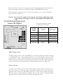
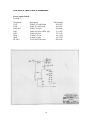
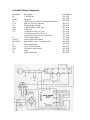
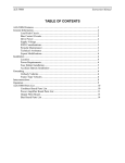
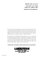
AM ERI TRON ALS-600
600 WATT NO TUNE
TM OS-FET AM PLIFIER
I NSTRUCTION M ANU AL
The Ameritron ALS-600 is a 600 watt output, solid state, linear amplifier using stateof-the-art, high voltage, RF TMOS FET devices in the power output section. The
ALS-600 provides continuous frequency coverage from 1.5 through 22 MHz with no
tuning adjustments. Broad band 5 pole low pass filters provide output harmonic
suppression in excess of all FCC requirements. Export modifications are available to
extend operation up to 30 MHz with a copy of a valid amateur license.
The ALS-600 uses four MRF-150 FET's operating a 50 volts in a double ended
push-pull parallel output configuration. High quality RF components combine with
an accurate peak detecting directional coupler, front panel adjustable ALC circuit
with automatic SWR fold-back, and one switch frequency selection to make this one
of the easiest to operate amplifiers available. The matching power supply, ALS600PS, is shipped factory wired for 120 volt, 50/60 Hz power mains and is easily
converted to other supply voltages between 100 and 240 volts.
PLEASE READ THIS MANUAL BEFORE OPERATING THIS EQUIPMENT !
116 Willow Road
Starkville, MS 39759 USA
662-323-8211
Version 2 Printed
in U.S.A.
Table of Contents
Amplifier Features .....................................................................................................…2
Power Supply Features………………………………………………………………...3
General Information .................................................................................................…..3
Amplifier........................................................................................... ……...…..3
Power Supply ...................................................................……………………3
Export Modifications ..........................................………………………..…….4
Technical Assistance ...............................................................…………...…...4
Amplifier Circuitry.....................................................................................................…4
Wattmeter Circuits........................................................…………………….….4
ALC (Automatic Level Control) .........................................…………..………5
Thermal Overload ............................................................………………..……6
Load Fault Indicator ..........................................................……………………6
SWR Considerations............................................……………………………...7
Power Supply Circuitry ............................................................................................….7
Line Voltage Modifications.....................................…………………………...7
High Voltage Section.....................................................……………………….8
Primary Circuit .......................................................................................…......... 8
Low Voltage Circuits............................................................. ................….......... 9
Installation..........................................................................................................……....... 9
Amplifier Location.............................................................................:.....…....... 9
Power Supply Location............................................. ................ .............…........ 9
Grounding ...............................................................................................…...... 10
Power Requirements.................................................................................…..... 10
Interconnections..................................................................................................…....... 11
Operation ............................................................................................................…....... 13
SSB Operation.........................................................................................…....... 13
CW Operation.............................................................................................….... 13
RTTY, FM and Other High Duty Cycle Operation ........................................... 13
AM Operation.............................................................................................….... 14
Drive Power Requirements .......................................................................…..... 14
Amplifier Operation................................................................................:...............….... 15
Periodic Maintenance..................................................................................….... 16
ALS-600 Parts Lists & Schematics...........................................................................…. 17
Meter/ALC Board..........................................................................................…. 17
PA Board..............................................................……........................................19
Output Filter Board........................................................................................…..20
LED Board................................................................................:..............…....... 22
SWR Detect Board...................................................................................…....... 23
ALS-600 Chassis Components......................................................................….. 24
ALS-600PS Parts Lists & Schematics........................................................................…..25
Power Supply Board.....................................................................................……25
ALS-600PS Chassis Components..................................................................…..26
Amplifier Features
Rugged devices. The ALS-600 uses four rugged RF power FET
Fast warm-up time. The ALS-600 has no vacuum tubes to warm
No tune operation. Tuning adjustments are not necessary. A simple one knob selector
switch permits operation on frequencies between 1.5 and 22 MHz.
ALC protection. The output and reflected powers are monitored and control the exciter
ALC voltage. This helps prevent damage to the amplifier.
Front panel ALC control. This unique Ameritron feature allows easy front panel
adjustment of the ALC threshold to control power output.
Load Error Protection. The PA load impedance is monitored and the amplifier is
bypassed if the band switch or the external load is incorrect.
Illuminated power/SWR meter. The ALS-600 has an illuminated cross-needle peak
reading RF power meter. Accurate directional coupler and peak storage circuits give
simultaneous forward and reflected peak power readings and also indicates load SWR.
Operate/Standby switch. This switch allows the amplifier to be by-passed for "barefoot" operation without turning the main power switch off and on.
Transmit and ALC Indicator LED's. Front panel LED's provide an indication of
amplifier keying by the exciter during operation and ALC output voltage.
12 volt auxiliary jack. This jack supplies +12v to operate low current
Thermal Overload Protection. The transmit relay in the amplifier is disabled if
excessive heatsink temperatures are reached.
Compact size. The ALS-600 weighs only 12.5 pounds and measures 6"H x 9.5"W x
12"D.
Power Supply Features
Multi-voltage heavy duty transformer. A unique "buck-boost" winding allows
compensation for up to six different power line voltages centered on 115 and 230 volts.
This versatile Ameritron feature maintains optimum voltages on the amplifier components
for maximum performance and life.
Choke input filtering. The ALS-600PS standard power supply uses an input choke to
provide a low power factor to the power lines. This reduces the peak currents drawn from
the line and improves the voltage regulation of the supply.
Step-start circuit. This circuit uses a relay and resistor to limit the inrush current to the
power supply. This circuit extends the life of the power supply components.
Current and output voltage metering. An illuminated cross needle meter monitors the
output voltage and current of the 50 volt output line.
General Information
Amplifier
The Ameritron ALS-600 is a 600 nominal watt output, solid state, linear amplifier using
state-of-the-art, high voltage, RF TMOS FET devices in the power output section. The
ALS-600 provides continuous frequency coverage from 1.5 through 22 MHz with no
tuning adjustments. Broad band 5 pole low pass filters provide output harmonic
suppression in excess of all FCC requirements. Export modifications are available to
extend operation up to 30 MHz with a copy of a valid amateur license.
The ALS-600 uses four MRF-150 FET's operating at 50 volts in a double ended push-pull
parallel output configuration. High quality RF components combine with an accurate peak
detecting directional coupler, front panel adjustable ALC circuit with automatic SWR foldback, and one switch frequency selection to make this one of the easiest to operate
amplifiers available. The matching power supply, ALS-600PS, is shipped factory wired for
120 volt, 50/60 Hz power mains and is easily converted to other supply voltages between
100 and 240 volts.
Power Supply
The ALS-600PS power supply is designed to power the ALS-600 amplifier from 50 to 60
hertz ac power mains that range from 100 to 130 and 210 to 240 volts. All ALS-600PS
supplies are wired for standard 120 volt systems and are shipped with a NEMA 5-15P
three wire plug.
This supply will safely provide the power required to operate the ALS-600 in typical
continuous amateur service at 600 watt output levels. The ALS-600PS power supply
supplies the three do voltages required by the amplifier unit. The high voltage section
supplies approximately 60 volts no load and 50 volts at a load current of 20 amperes.
Export Modifications
A simple modification will allow operation on frequencies up to 30 MHz. A parts kit to
make this modification is available by sending a written request for the export
modification kit, item no. 19-10600, along with a copy of your valid amateur license to
Ameritron. There is charge for this kit. Export models are shipped with this modification
installed. The ALS-600Y is the export for 115-130vac operation and the ALS-600X is the
export model for 220-240 operation.
Technical Assistance
Technical assistance is available by calling (662) 323-8211 during our normal business
hours (8:00 to 4:30 Central Time on weekdays) for questions that are not answered by the
technical information sheets. We are happy to provide personal assistance if you need
more detailed help. Please have the following information available so that we can
accurately assist you with any problems:
1.
The model and serial number of the unit.
2.
The date of purchase and the dealer.
3.
A brief description of the station equipment and antenna system.
4.
A complete description of the problem along with any abnormal meter readings.
Written assistance is also available. Due to time delays in processing mail, please allow at
least three weeks for a written reply.
AMERITRON
116 Willow Road
Starkville, MS 39759
Tel: (662) 323-8211
Fax: (662) 323-6551
Amplifier Circuitry
Wattmeter Circuits
The BIAS/WM/ALC board contains the peak power detector circuits. The rear panel
directional coupler connects to IC101D/C. IC101D/C drives Q101/102 to charge
C103/106 to the peak voltage from the directional coupler. C103/106 is lightly loaded by
ICIOIA/B and R103/107. This allows enough "hang" time for the meter to accurately
indicate peak power levels.
Accurate forward peak power reading are obtained under mismatched load conditions
when the reflected power is deducted from the forward power readings.
The average and peak envelope power values are EQUAL on CW, FSK and FM ( modes
that do not have amplitude changes in the carrier). The average power level of voice or
other complex waveform signals has NO SET RATIO of peak to average power.
ALC (Automatic Level Control)
The ALC circuit functions by using a comparator (IC103A) to reduce the exciter drive
power if the output power of the ALS-600 exceeds a preset value. The ALC circuit also
reduces the drive power if the SWR increases while operating with the ALC controlling the
amplifier output power level. The ALS-600 ALC output should be connected to the
proper exciter external ALC connection point with a shielded audio type cable. Consult the
exciter manual for the proper exciter connection details.
Operation at high audio gain levels on SSB with ALC has the same effect as an RF speech
compressor. RF compression increases SSB "talk power". Background noise pickup also
increases when the exciter gain is operated at high levels to increase compression. Audio
distortion does not normally occur with this type of speech processing if the ALC circuit
in the exciter is properly designed.
Do not attempt to limit the CW power more than a few percent solely with the amplifier
ALC circuit. Using the amplifier ALC to reduce CW power levels may result in pumping of
the output power during dots and dashes. The "ALC SET" control will be correctly
adjusted when the "ALC" LED gives a small flash while transmitting on CW. This can be
accomplished by adjusting the "ALC SET" control on the front panel so that the "ALC"
LED just barely lights when the desired power level power level (below 400 watts) is
reached with a steady carrier.
The ALC circuit can be used to reduce power by any amount on constant amplitude
carrier modes such as RTTY or FM. The ALC can not cause modulation distortion or
pumping on these modes.
Never use the ALC to control the level of AM transmissions. Using the amplifier's ALC
circuit to control AM output power will cause pumping of carrier amplitude on AM
transmissions during modulation.
The ALC indicator on the front panel of the ALS-600 is driven by comparitor IC3B.
Resistors R24 and R25 set the turn-on level of the front panel "ALC" indicator. Factory
selected resistor values cause the "ALC" LED to illuminate as soon as negative ALC
voltage begins to appear at the ALC output jack.
If the exciter used with this amplifier does not "fold back" until appreciable ALC voltage is
developed, the "ALC" LED may become fully lit even under operating conditions that are
producing very light ALC action.
Caution: There are no industry standards for transceiver or exciter ALC input voltage
levels, input resistance, or attack and decay times. While every attempt has
been made to make the ALC circuit in this amplifier compatible with various
exciters, the exact operation of the ALC circuit will vary with the exciters
response to external ALC control voltages. This ALC circuit will function with
negative voltage ALC control systems requiring less than 10 volts.
Thermal Overload
The ALS-600 has a built in thermal cut-out that by-passes the amplifier if excessive heat
sink temperature is produced. This circuit minimizes the risk of excessive temperature
damage to the FET's and other components.
If the amplifier "XMT" LED remains lit while the amplifier suddenly stops transmitting
the thermal overload has probably tripped. If the thermal overload has tripped full
exciter power will appear on the RF output meter.
The thermal overload resets automatically and all amplifier functions are restored when
heat sink temperature returns to a safe value.
The usual cause of thermal overload is excessive heat buildup during a transmission period
longer than a few minutes. To correct this condition be sure that the power level and duty
cycle limits are being followed, that the SWR is as low as possible, and that the cooling is
not being hampered by air flow restriction or excessive inlet air temperatures.
Load Fault Indicator
The "LOAD FAULT" LED indicator will light and the amplifier will not go into a
transmit mode if the band switch is set on the wrong frequency range, if the load SWR is
excessive, or if the output power level is excessive.
To reset a "LOAD FAULT" indication:
l.) Determine and correct the cause of the problem.
2.) Place the amplifier "STANDBY-OPERATE" switch to "STANDBY" and then back to
"OPERATE".
The load fault detector circuit is located on the output filter board and measures the
reflected power presented by the output filter network and the SWR directional coupler.
The sensitivity of the circuit is adjusted by R304 and R601. C324 is a factory adjustment
that controls the impedance of the detector circuit. This capacitor is adjusted for minimum
detector voltage on 7 MHz with a 50 ohm load. Do not adjust any components in this
circuit without consulting the factory.
SWR Considerations
A high SWR (Standing Wave Ratio) causes higher voltages and/or currents to appear at
the output connector of the amplifier. This problem occurs with all amplifiers regardless
of whether tubes or semiconductors are used in the output stage.
Vacuum tube amplifiers have the reputation of handling high SWR's quite well. This
reputation probably exists for two reasons. First, most vacuum tube amplifiers use
adjustable output networks. Second, nearly all vacuum tubes handle momentary overloads
extremely well.
In tube amplifiers that have tunable Pi or Pi-L networks, the only components affected by
a high load SWR are those between the loading adjustment capacitor and the output
connector. When the output network is properly adjusted the SWR can not affect tube life.
The TMOS FET devices used in the ALS-600 have nearly the same momentary overload
tolerance as vacuum tubes. The low pass output network in the ALS-600 is much broader
in bandwidth and less sensitive to load changes than the networks used in tube type
amplifiers.
This makes the ALS-600 much less sensitive to frequency and SWR changes than the best
"no- tune" tube amplifiers but not as good as adjustable pi-networks. The ALS-600's
multiple section output network and push-pull output configuration offers much better
harmonic suppression than most tube amplifiers regardless of load SWR.
The only danger presented by a high SWR in this amplifier is that the current and power
dissipation in the output devices may exceed safe limits. Lengthy operation with high SWR
at high power levels can result in heat damage and failure of the FET devices. If the
reflected power exceeds 50 watts the power level should be reduced until the reflected
power indicated on the internal meter is 50 watts or less on peaks. At approximately 75
watts of reflected power the internal safety circuitry will disable the amplifier.
Power Supply Circuitry
Line Voltage Modifications
The line input voltage of the ALS-600PS can be changed by moving jumper wires on the
power supply printed circuit board to new locations. The ALS-600PS is wired for standard
120 Vac operation unless otherwise indicated.
Warning: Never remove the cover of this unit while it is connected to the power line.
Never solder or unsolder without eye protection.
Refer to the chart on below for the proper location of the primary wiring. This chart lists
the proper jumper connections for different ranges of MAXIMUM line voltage.
The standard line voltage in the USA is NOT 110 and 220 volts. It is almost ALWAYS
above 120 volts or 240 volts.
Caution: Never exceed the voltage in this chart for each wiring configuration. If the
output voltage of this supply exceeds 65 volts damage to the amplifier may
occur.
ALS-600PS Power Supply Board
Jumper Pad Diagram
For the following line voltages
jumper the correct pads.
AC LINE
VOLTAGE
RANGE
PRIMARY
BUCK BOOST
95-110
A TO B C TO D
E TO 2 F TO 1
105-120
A TO B C TO D
E TO F
115-130
A TO B C TO D
E TO 1 F TO 2
200-220
B TO C
E TO 2 F TO 1
210-230
B TO C
E TO F
220-240
B TO C
E TO 1 F TO 2
High Voltage Section
The high voltage section of the ALS-600PS uses a full wave bridge rectifier. DC filtering
is accomplished with a large swinging choke (T1) and a high quality computer grade
capacitor (C5). A pair of 100 ohm resistors (R5,6) absorb enough bleeder current to
prevent the output voltage from soaring under low load currents. The output voltage and
current of this section are monitored by a illuminated dual needle meter (M2a/2b).
Primary Circuit
10 ohm resistor (R602) limits the line current during the filter capacitor charge time to
lower the stress on the power supply components. When the 14 volt control line
approaches full voltage relay (RLY601) bypasses the 10 ohm resistor (R602) and applies
full line voltage to the transformer primary. The 10 ohm resistor is protected from
supply shorts by a 2 amp slow-blow fuse (F601) during the start-up.
A separate 10 volt transformer winding can be connected either to either oppose or add to
the power line voltage. This allows the 115 volt maximum voltage primary windings to be
adjusted to provide the proper voltage. Use of the buck-boost winding allows maximum
primary voltages of either 100, 110, and 120 volts maximum voltage or 210, 220, and 230
volts maximum voltage at either 50 or 60 hertz.
The primary circuits are fused by two fuses (171,2) that are rated at 15 amperes at 100
volts, 12 amperes from I10 to 120 volts or 8 amperes from 220 to 240 volts. Since the
current demand and the power factor of this supply are so low Ameritron does not
recommend operating this supply on the higher voltage lines (210 to 240 volts) unless
lower voltages are unavailable.
Low Voltage Circuits
The low voltage power supply sections supply 14 volts positive at 2 amperes maximum
with a full wave grounded center tap supply for 'control, lights and also to power the bias
voltage regulator and the circuitry of the Bias/ w attmeter board in the ALS-600. This low
voltage circuit is protected by a 2 ampere fuse (F602) located on the power supply printed
circuit board.
A separate half wave rectifier supplies the low current necessary to operate the ALC
circuitry in the ALS-600. This circuit is protected by a 10 ohm 1/4 watt resistor (R601).
Installation
Amplifier
Do not locate this amplifier in excessively warm locations, near heating vents or near
radiators. Be sure that air can circulate freely around and through the amplifier cabinet. Do
not obstruct the air inlets at the rear of the amplifier and the outlet air holes on the lower
right side of the amplifier cabinet.
The best location for the amplifier is one that allows the meters to be easily read and the
controls accessed during operation. The length of interconnecting control cables are not
critical. The control leads should be made from good quality shielded cables. Low level
audio cables sold for use with stereo and VCR equipment are ideal. The RF cables should
be kept as short as possible.
Power Supply Location
The best location for this power supply is one that is away from devices that are sensitive
to magnetic fields. The meter and fuses should accessible for service. Do not obstruct the
air inlets at the rear of the power supply and the outlet air holes on the upper right corner
power supply cabinet
Caution:
The choke in the power supply emits strong magnetic fields. Never place
magnetic tapes, computer disks or other magnetic sensitive devices within
18 inches of the cabinet of the ALS-600PS.
Grounding
The station ground buss should be connected to a good earth and RF ground. Use the
heaviest and shortest connections possible. The best ground leads are smooth and have a
large surface area. Braiding (including standard coaxial cable shield) has a high RF
resistance and should be avoided unless the lead needs to flex. The best conductors for
ground connections are copper flashing or copper foil. Solid copper wire can be used and
will closely approximate copper flashing if multiple ground leads are used and separated at
least a few inches apart.
Water pipes can be used for an earth connection if the plumbing is all metallic pipes. The
water meter or any other insulative junction should be bypassed with a jumper wire
clamped to the pipe at both sides of the meter.
Multiple ground connections are superior to a single ground connection. Ameritron has a
technical information sheet with addition suggestions for grounding.
No grounding terminal is provided for the power supply since it does not generate any RF
signals. A safety ground is provided by the power line neutral ground through the line cord
and plug.
Warning: Never remove or defeat the electrical safety ground connection on the plug
of this supply or a shock hazard may develop.
Power Requirements
Caution: The ALS-600 is not designed for operation for 12 Vdc operation.
The ALS-600PS power supply is designed to match the ALS-600 amplifier. The ALS600PS
provides 50 volts do at 25 amperes along with 12 volts positive and negative at low current
for the control and bias circuits of the amplifier.
The power supply requires less than 12 amps at 120 Vac or 6 amps for 240 Vac. The output
voltage of the supply should be kept below 65 Vdc at no load for maximum component life.
If the no load output voltage exceeds 65 Vdc you must change the change the input line
voltage of the ALS-600PS. Refer to the "Line Voltage Modifications" section in this
manual.
Interconnections
1.
Connect the RF output (ant) of the exciter to the RF IN (SO-239) of the ALS-600
with a good quality 50 ohm cable capable of handling 100 watts.
2.
Connect the station antenna system to the RF OUT (SO-239) connector with 50 ohm
coax that will safely carry 600 watts. This is where the Low-Pass filter, antenna tuner,
antenna switch and other accessories connect.
3.
Use shielded audio type cable with standard male phono (RCA) connectors to connect
the RELAY jack of the ALS-600 to the transceiver or transmitter, normally open,
amplifier relay terminal. This connection has 12 volts open circuit and supplies less
than 100 mA of current when pulled to ground. There is a back pulse canceling diode
in the amplifier for exciter protection.
4. Connect the ground stud (GND) on the amplifier to the station ground buss with as
short a lead as practical.
5.
Connect the ALC jack to the exciter ALC terminals with a shielded audio type cable
and standard phono connector.
6. Connect the female power connector from the ALS-600PS supply to the multi-pin
male connector on the ALS-600 rear chassis.
7.
The 12V connector can be used to supply 12-14 Vdc at less than 200 mA for station
accessories.
13
Operation
This amplifier is equipped with a switch on the front of the Amplifier's Power Supply
labeled Normal/RTTY. This switch is used in the normal position for SSB and CW
operation. The RTTY position is used for continuous carrier modes. This position will
limit the voltage to about 42Vdc no load. This will limit the output power to 350 watts. In
the RTTY position, the amplifier can be operated with 10 minute key down with 50% duty
cycle.
The Amplifier's back panel has an ALC limit control. This control is to limit the amount
of ALC voltage sent to the transceiver. This is necessary due to there is not a standardize
ALC voltage on transceivers. To set the ALC limit control, adjust the ALC set knob on
front of the amplifier to 10 (fully clockwise). Apply enough drive into the amplifier until
the amplifier's power meter reads about 400 to 500 watts. Note: The amplifier's power
meter should never exceed 700 watts at anytime. Plug the ALC into the back of the
amplifier (if not already done). Turn the ALC set knob (on front of amplifier) to 0
(counter-clockwise). Key amplifier with RF applied. Adjust the ALC limit control (on back
of amplifier) until the ALC light on front of amplifier just comes on. No other adjustment
needs to be done to the ALC limit control, unless a different transceiver is used. The only
adjustments for ALC will be done on front of the amplifier. Follow the operator's manual
for ALC adjustment.
The following sections describe how to adjust the exciter and ALC control for proper
operation. If the ALC is not used the exciter output controls must be used to limit the
power to the levels described in the text that follows.
SSB Operation
SSB voice operation normally does not have transmit time limits. Reflected power levels
should be kept below 50 watts peak on SSB.
The most accurate way to maintain linear operation on SSB is with an oscilloscope. The
output waveform should be closely observed for clipping or reduction of peaks and should
closely resemble the waveform that the exciter produces barefoot.
If any peak clipping is evident the output power should be reduced until peak clipping is at
a minimum.
The proper operating level can also be determined by operating the exciter at full power
output (not to exceed 100 watts peak) and normal voice modulation with the amplifier
"ALC SET" control fully clockwise. The "ALC SET" control should be adjusted until the
amplifier's RF output meter just begins to drop.
The exciter output level should then be reduced with the audio gain control or output
control until the desired amount of ALC compression is obtained. See the ALC
(Automatic Level Control) section for more details.
14
CW Operation
The exciter output should be restricted to a level that limits the amplifier to 500 watts
output on a steady carrier or 50 watts reflected power, whichever is greater.
The ALC should not be used to control the power level more than a few percent on CW.
The "ALC" LED should just barely light or flash on CW.
RTTY, FM and Other High Duty Cycle
The transmitting duty cycle, ambient temperature, supply voltage, fan speed and the load
SWR all play important roles in determining the transmit time limit on high duty cycle
modes.
To minimize noise, Ameritron uses only enough fan speed to cool this amplifier for typical
amateur usage. If heavy duty cycle operation is planned the following guidelines should be
followed.
The output power can be reduced to assist with cooling. This is not the most effective
method of improving performance since the power must be reduced 5 times to cut the
heat dissipation in half. The exciter output should be restricted to a power level where less
than 200 watts output or 25 watts reflected power is obtained on long duty cycle modes.
The fan speed should be increased by replacing or supplementing the airflow from the
standard fan. A fan that delivers at least 80 CFM airflow at .l" of static pressure, such as
the EBM W2S107-AA15-39, will double the cooling and allow 500 watt RTTY
transmissions with 2 minute on, one minute off duty cycles.
The high voltage power supply can be reduced to increase the efficiency at lower output
levels. At 30 volts the ALS-600 will deliver 275 watts of output power. This will allow a
100% duty cycle with any fan delivering more than 40 CFM at .08" of static pressure, such
the EBM W2S107-AD21-39, or a 5 minute on, two minute off duty cycle with the
standard fan.
Either the exciter drive level or the amplifier "ALC SET" control can be adjusted to limit
the power output in the RTTY and FM modes.
AM Operation
The carrier power of any linear amplifier is restricted on AM to one fourth of the peak
envelope output power. With this amplifier the maximum carrier power on AM will be
around 150 watts.
Proper modulation AM is indicated by observing the ratio of unmodulated carrier power
to the power indicated on voice modulation peaks. This rotation should be
approximately 4:1.
Never use the ALC to control the power on AM. The "ALC SET" control should be set in
the maximum clockwise position.
Drive Power Requirements
The ALS-600 requires less than 100 watts of drive to produce full output power.
Exceeding 100 watts of drive for long periods of time may cause component failures.
Exceeding 100 watts of drive for short periods will cause distortion and increase the
bandwidth of the transmitted signal.
Follow these instructions in numerical order. Consult the manual for the exciter, if
necessary.
Be sure the power supply transformer is correctly wired for your line voltage.
"Line Voltage Modifications" section for wiring details.
See the
1.
Set the ALS-600 front panel switches as follows:
ON-OFF to OFF
OPERATE-STANDBY to STANDBY
2.
Plug the ac line cord into the proper voltage outlet.
3.
Place the power switch in the ON position. The meter lamps should light and the
fans on the power supply and the amplifier should start.
4. Check the voltage on the power supply meter. The voltage should be between 55 and
65 volts at this step. If the voltage is outside this range then check the line voltage with
an accurate meter and make sure the power supply primary wiring is correct.
5.
Set the amplifier's frequency range switch to the same frequency as the
6. With the amplifier still in STANDBY, transmit into the expected 50 ohm RF load with
the exciter. Measure the SWR on the amplifier's SWR scale or with an external SWR
indicator.
Caution: Do not operate this amplifier at full power with an SWR above 2:1. See the
SWR Considerations section on page 7.
7. Place the amplifier in the OPERATE position The TRANSMIT LED should light
when the exciter is keyed. With no RF drive the idling current should be less than 1
amp on the power supply meter.
8. The ALC control is usually properly adjusted if the ALC LED just flashes when the
desired peak output power is reached. The audio or power output control on the
exciter can be adjusted to control how "heavily" the ALC is used. The higher the
exciter power (gain) control is adjusted the more compression the ALC circuit
provides.
The best signal quality occurs when the ALC LED occasionally flashes. The most SSB
signal "punch" will occur if the LED continuously flashes.
Full output levels of 500 watts CW should be obtained with drive levels of under 100
watts. Peak envelope output levels on SSB may reach as high as 800 watts depending on
voice and exciter characteristics. The lowest IMD and splatter will be obtained if the
amplifier is operated at an output level slightly below the maximum level obtainable.
Periodic Maintenance
The lack of extremely high voltages in this unit eliminates the chance of dirt and dust
causing high voltage arcing. The only requirement for periodic maintenance is to monitor
the amount of dirt and dust in the amplifier and the power supply. Whenever there is a
noticeable accumulation of dust that may affect cooling, air can be used to blowout the
equipment.
The fan area on the amplifier should be inspected every few months if the amplifier is
operated in a very dusty environment. If there is a large amount of dust on the fan it is
probably a good time to blow the dust out of the amplifier and power supply with
moderate air pressure.
A soft bristled brush and a small amount of alcohol can be used to clean stubborn dust
from the fan screen or the other components. Be careful not to get any cleaning
compounds on the relay contacts or the switches. Ameritron has a technical information
sheet on relay and switch maintenance.
Caution: Never remove the cover of the amplifier or the power supply, with the power
supply plugged in to the electrical outlet.
ALS-600 Parts Lists & Schematics
Meter/ALC Board
50-0600-1
Designator
C101,102,104,105,109,
107,112-115,117-123
C103,106
C108,116
C110,111
D101
D102-105,107
D106
IC101
IC102
IC103
7103
7104,105
7106
Q101,102
8101,106,115
8102
8103,107
8104,105,108,113
8109
RI 10
8111,119,120,123,127
8112
8114
R115
R116
RI 17,118,125
R121
8122
8124
R126
Description
0luF 50v disc
2.2uF 50v radial lead electrolytic
47uF 50v tantalum
not used
not used
1N34A diode
5.lv 1/2w Zener diode 1N4734
quad op-amp LM324N
8v reg 751,08ACP
dual op-amp LM35AN
2 pin header
8 pin header
10 pin header
2N3904
4.7k 1/2 watt
1M 1/4 watt
470k 1/4 watt
22k 1/4 watt
50k trim pot
5k trim pot
10 ohm 1/2 watt
3.3k ohm 1/4 watt
6.8k 1/4 watt
100K ohm 1/4 watt
220K 1/4 watt
1 k 1/4 watt
33 ohm 1/2 watt
2.2k 1/4 watt
1 M ohm 1/4 watt
470 ohm 1/4 watt
Part number
200-0416
203-0225
203-0530
300-0346
301-4734
311-0324
307-0012
311-0725
612-0102
612-0108
612-0110
305-0645
101-3470
100-6100
100-2470
100-4220
104-0400
104-5020
101-1100
100-3330
100-3680
100-5100
100-5220
100-3100
101-1330
100-3200
100-6100
100-2470
18
PA Board
50-0600-2
Designator
C201-203,217
C204-207,209-212
C208
C213,214,220-226
C215
C216
C218,219,232,233
FB201,202
Q201-204
8201,204,214,211
8202,205,212,215
8203,206,213,216,221-224
8207,208,217,218,231-234
8209,210,219,220
8225-230
T201
T202
T203
Description
not used
1 uF 50V disc
470 pF 500V DM 15
.33 uF 100V multilayer
47 uF 100V mylar
100 uF 100V radial lead electrolytic
360 pF 500V
ferrite bead w/ Teflon sleeving
MRF-150 RF TMOS FET
3.3k 1/4 w
5k trim pot
lk 1/2w
18 ohm 1/2w .
1 ohm 1/2w
22 ohm 2 watt MOX
input transformer
feedback transformer
output transformer pair
1
Part Number
200-0745
208-5440
205-1334
201-1474
203-1007
208-5688-1
403-0508
305-6150
100-3330
104-2520
100-3100
101-1180
101-1010
103-2220
406-2600
406-2601
406-2602
Output Filter Board
50-0600-3
Designator
C301,308
C302,307
C303,309
C304,310
C305,311,319
C306,312,317
C313,314
C315,316
C318
C320
C321-323,326-328
C324
C325,329
C330
D301
D302,303
D304
L301,306
L302,307
L303,308
L304,309
L305,310
RLY301
R301
R302
R303
R304
R305
R306
R307
R308
R309
R310
SW301
Description
not used
180 pF* 1000v CDV-30
270 pF* 1000v CDV-30
360 pF* 1000v CDV-30
680 pF* 1000v CDV-30
1500 pF* 1000v CDV-30
160 pF* CDV-30
220 pF* CDV-30
2700 pF* CDV-30
27 pF 500 v mica
01 uF 50 v disc
3-12 pF 500V trim cap
150 pF 500V DM15
33 uF 50V Multilayer
2N6564
2N3904
1N34A
8.5 turn 1/2" ID air wound
8 pass toroid
10 pass toroid
14 pass toroid
22 pass toroid
3PDT 12 Vdc coil relay
35 ohm 50watt non-inductive resistor
82 ohm 1/2 watt
3.3K 1/4 watt
2.5K sub horz. trimpot
2.2K 1/4 watt
I OK ohm 1/4 watt
470 ohm 1/4 watt
10 ohm 1/2 watt
IK 1/4 watt
10K 1/4 watt
bandswitch
* Critical components.
Part Number
208-6181
208-6271
208-6361
208-6681
208-6152
208-6161
208-6221
208-6272
208-5270
200-0416
204-0150
208-5396
205-2233-1
321-6564
305-0645
300-0346
10-13850
10-14168
10-14161
10-14214
10-14222
408-6140
103-2230
101-1820
100-3330
104-2520
100-3220
100-4100
100-2470
101-1100
100-3100
100-4100
SW25000448
22
LED Board
50-0600-4
Designator
Description
CR401
CR402
CR403
J401
R401
R402
Green LED
Yellow LED
Red LED
10 pin header
470 ohm 1/4 watt
1k Potentiometer
Part Number
320-0500
320-0300
320-0522-1
612-0110
100-2470
105-1301
SWR Detect Board
50-0600-5
Designator
Description
C501,502
C503
C504
C505,506
C507
D501,502
R501
R502
R503,504
T501
150 pF 1kV disc cap
not used
33 pF 1 kV Disc
.01 uF 50 Vdc
3-12 pF 500V TrimCap
1N34A or equiv.
3.3k 1/4 watt
68 ohm 2 watt mox
not used
Pickup Toroid
Part Number
200-2150
200-2033
200-0416
200-0416
300-0346
100-3330
103-6800
10-14136
ALS-600 Chassis
Components
Designator
Description
Part Number
B1
for B 1
Cl-C5
C6-C7
C8
J1,J2
J3-J5
J6
Mla, Mlb
RI
R2
SW1,SW2
TMl
4.5" fan
fan filter screen
.01 50v disc capacitor
.01 250Vac capacitor
.01 kV disc capacitor
SO-239 jacks
phonojacks
Power connector plug
1000w/250w cross needle meter
1 K Potentiometer
470 Ohm 1/4 Watt resistor
rocker switch
Thermal overload switch
410-3138
410-4600
200-0416
200-2122
200-2121
610-2126
600-1225
610-5012
400-3588
105-1301
100-2470
507-1147
510-1170
24
ALS-60OPS Parts Lists & Schematics
Power Supply Board
50-0600-6
Designator
C603
C604
D601-603
F601
F602
R601
R602
RLY601
Description
2200uF 25v radial lead
220uF 25v radial lead
1N4007 or equiv.
2 amp slow blow NIDL type
2 amp fast blow
10 ohm 1/2 watt
10 ohm 10 watt
12Vdc SPST NO relay
26
Part Number
203-0207
203-0565
300-0266
755-1102
755-1150
101-1100
103-9702
408-6148
ALS-600PS Chassis Components
Designator
B2
for B2
C5
C3,4
D1
F601
F602
F1,2
F3
for F3-5
M2a, M26
P1
R3,4
R5,6
T1
T2
Description
3" muffin fan
fan guard
15000 uF 80 We capacitor & mounting bracket
0luF 250 Vac disc capacitor
50 amp bridge rectifier
2 amp slowblow IvIDL type
2 amp AGC
15 amp fuses for 95-110 Vac,
12 amp fuses for 105-130 Vac or
8 amp fuses for 200-240 Vac operation
25 amp high voltage
chassis mount fuse holders
dual needle 60 volt / 25 ampere scale
Power supply plug
150 K 1/4 watt resistor
100 ohm 50 watt resistor
choke
power transformer
Part Number
410-3583
410-4584
203-0680
200-2122
300-9646
755-1102
755-1149
755-1426
755-1412
755-1432
755-1428
755-2148
400-3600
610-6012
100-5150
103-9810
406-1646
406-3002
116 Willow Road
Starkville, MS 39759
USA 662-323-8211
LIMITED WARRANTY
Ameritron warrants to the original purchaser that this product shall be free from defects in material
(except tubes and RF output transistors) or workmanship for one year from the date of original
During the warranty period, Ameritron (or an authorized Ameritron service facility) will provide free of
charge both parts (except tubes and RF output transistors) and labor necessary to correct defects in
material or workmanship.
To obtain such warranty service, the original purchaser
(1) Complete and send in the Warranty Registration Card.
(2) Notify Ameritron or its nearest authorized service facility, as soon as possible after discovery
of a possible defect, of:
(a) the model number and serial number, if any:
(b) the identity of the seller and the approximate date of purchase;
Correct maintenance, repair, and use are important to obtain proper performance from this product.
Therefore, carefully read the Instruction Manual. This warranty does not apply to any defect that
Ameritron determines is due to:
(1) Improper maintenance or repair, including the installation of parts or accessories that do not
conform to the quality and specifications of the original parts.
(2) Misuse, abuse, neglect or improper installation.
(3) Accidental or intentional damage.
All implied warranties, if any, terminate one (1) year from the date of the original purchase.
The foregoing constitutes Ameritron's entire obligation with respect to this product, and the original
purchaser and any user or owner shall have no remedy and no claim for incidental or consequential
damages. Some states do not allow limitations on how long an implied warranty lasts or do not allow
the exclusion or limitation of incidental or consequential damage, so the above limitation and exclusion
may not apply to you.
This warranty gives specific legal rights and you may also have other rights which vary from state to
state.
PLEASE RECORD THIS INFORMATION
Model Number
Serial Number
Date of Purchase
Purchased From
Warranty Card Mailed On